
1909_A001
12
Deriving Deviations from First Principles Appendix I APPENDIX Deriving Deviations from First Principles ntroduction For the users of structured hazards analysis techniques such as Hazard and Operability (HAZOP) analysis and Failure Modes and Effects Analysis (FMEA) there are distinct differences and alternative applications for their usage. Although HAZOP is very well established and practiced, its exact basis is rather more empirical and subject to considerable variations. This situation has significant disadvantages including inconsistency of methodologies and lack of agreed criteria for assessment. In the field this has lead to a number of different approaches so that repeatability, a hallmark of the scientific method, is largely absent. The problem is the inability to derive Deviations for HAZOP from first principles. This has lead to experience and empirically based methods filling the gap. The se methods are more subjective and dependent upon those executing the analyses. Therefore considerable diversity in results is very frequent. The question is thus one of who's or what method should be used for a particular application. This clearly leads to the demand for a basic root methodology that removes it from the vagaries of subjectivism. This paper addresses the situation by proposing Component Functional Analysis (CFA) as the root methodology. It also shows how Deviations (for HAZOP) may be derived through YADEM © 2003 by CRC Prcss LLC
-
Upload
feliciasetiawan -
Category
Documents
-
view
212 -
download
0
description
HAZOP
Transcript of 1909_A001

7/17/2019 1909_A001
http://slidepdf.com/reader/full/1909a001 1/12
Deriving Deviations from First Principles
Appendix I
A P P E N D I X
Deriving Deviations from
First Principles
ntroduction
For the users of structured hazards analysis techniques such as Hazard and Operability
(HAZOP) analysis and Failure Modes and Effects Analysis (FMEA) there are distinct
differences and alternative applications for their usage. Although HAZ OP is very well
established and practiced, its exact basis is rather more empirical and subject to
considerable variations. This situation has significant disadvantages including
inconsistency of methodologies and lack of agreed criteria for assessm ent. In the field this
has lead to a number of different approaches so that repeatability, a hallmark of the
scientific method , is largely absent.
The problem is the inability to derive Deviations for HAZO P from first principles. This
has lead to experience and empirically based methods filling the gap. The se methods are
more subjective and dependent upon those executing the analyses. Therefore considerable
diversity in results is very frequent. The question is thus one of who's or what method
should be used for a particular application. This clearly leads to the demand for a basic
root methodology that removes it from the vagaries of subjectivism.
This paper addresses the situation by proposing Component Functional Analysis (CFA) as
the root methodology. It also shows how Deviations (for HA ZOP) m ay be derived through
YADEM
© 2003 by CRC Prcss LLC

7/17/2019 1909_A001
http://slidepdf.com/reader/full/1909a001 2/12
Deriving Deviations from First Principles
Appendix
the concomitant identification of malfunctions and counter functions
rom
CFA using
FMEA. It shows how both FMEA and HAZO P are closely related through considera tion
of functional envelopes,
Critique
o
Current Methods
o
Structured HazardsAnalysis
The main forms of process hazards analysis (PHA) include Guide Word HAZOP, FMEA
and What If analysis. The first two methods (HAZOP and FMEA) are highly structured
while What If has little structure and is largely experience based.
FMEA, the most structured of the two remaining methods, is widely used as
MIL
STD
629 in the defense, aircraft and automobile industries. The technique is relatively straight
forward and considers the failure modes of specific components.
Guide Word HAZOP, unlike FMEA, is dependent upon applying Deviations (and
Disturbances) £i-om the Design Intent. This method is som ewhat more com plex than
FMEA and is very widely used in the process industries.
Although highly structured from an applications standpoint Guide Word HAZOP
has
the
underlying weaknesses that the Deviations (for HAZOP) are assumed to be self evident,
which indeed they are not. With Guide Word HAZOP the deviations are obtained by the
application of Guide Words to Properties (which includes Parameters and Activities).
However the methodology for determining which Properties should be selected is not
obvious. Ellis Knowlton (Chemetics) has developed an approach based on the application
of Guide Words to Materials, Activities, Sources and Destinations: this requires
imagination and skill on the part of the user while the CC PS (ref. Guidelines to Hazards
Evaluation Procedures ,
ndedition) has endorsed the Parametric Deviation methodology.
Knowlton's method is most suitable for batch processes while the Parametric Deviation
methodology is m ore suitable for con tinuous processes.
© 2003 by CRC Prcss LLC
7/17/2019 1909_A001
http://slidepdf.com/reader/full/1909a001 3/12
Deriving Deviations from First Principles
One of the major problems with Guide Word HA ZOP, is that Deviations for HAZOP) may
be either over or under specified. This leads to wasted efforts or oversights respectively.
For example, it may appear to be obvious, for a process line, to examine High, Low,
Reverse Flow, High, Low Pressure, H igh, Low Temperature and so forth. But what is the
basis for this? Unfortunately, applying a non-structured basis to a highly structured
methodology leads to somewhat arbitrary results as the basis of a supposedly complete
analysis.
Under these circumstances who can dictate that one set of deviations is right and another
wrong? Furthermore if a specific methodology for deriving Deviations is correct, should
not those systems with the greatest potential for failure also be associated w ith the greatest
number/ range of Deviations? There is some good eviden ce, as this paper suggests, that
equipment, such as pumps and compressors) are underassessed using the current HA ZO P
methodology while other equipment is being ove r-assessed.
Component Functional nalysis
With any form of structured analysis the greater the number of assumptions and
simplifications the greater the tendency to compromise the methodology and its
effectiveness. By way of an analogy, computers, which are not programm ed to take short
cuts, are effective simply because the level of detail needed is not a constraint in program
execution. Insisting upon thoroughness, when it is affordable, is understandable. Settling
for less, because greater effort is required, may be a false econom y.
There is an oversimplification of the basic issues in structured process hazards analysis.
This has lead to overlooking of some very basic principles, namely the components
themselves, their contributional functionality and their failure to perform, in the functional
sense.
Unlike HAZO P, Component Functional Analysis CFA ) with FMEA requires no
simplifying assumptions. It requires a basic understanding of the systems being analyzed.
Y DEM
© 2003 by CRC Prcss LLC

7/17/2019 1909_A001
http://slidepdf.com/reader/full/1909a001 4/12
Deriving Deviations from First Principles
Appendix
The analysis requires breakdown into parts (i.e., no des, subsystems). Typically these are
line(s), vessel(s), heat exchanger(s), pump(s), com pressor(s) and so forth.
The
CFA
requires the parts to be broken down into components. By way of example,
consider a line passing from one point to ano ther as typically having isolation valves, flow
transmitter, control valve, piping, drain, vent etc. as components each having specific
h c t i o n s . Hence the line should be understood not simply as line but rather as an
integrated group of components, each with their own purpose, i.e., functions.
The corollary to knowing the function(s) of each component is that diametrically opposite
considerations, i.e., malfunctions, can be specified. In addition to malfunctions,
components may have functions that are mutually antagonistic; when this occurs these are
identified as counter functions. Following the listing of the malfunctions and counter
functions the conventional process of specifying Causes, Consequences, Safeguards and
Recommendations follows.
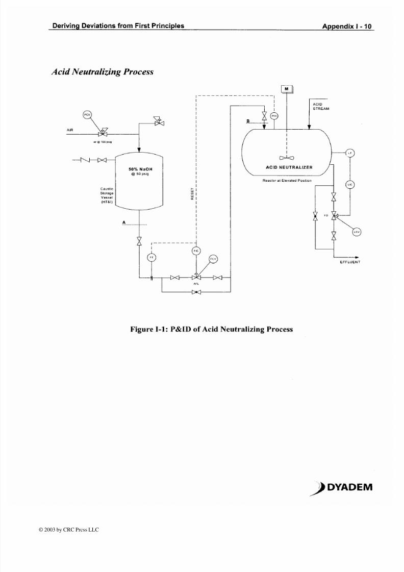
n example, as per the attached sketch, shows a transfer line from a caustic storage vessel,
automatically neutralizing
an
acid stream in a neutralizing vessel. CFA with
FMEA
applied is used to derive Deviations. It can be seen that the malfunctions are related
to
failure modes. It is not necessary to specify the Design Intent because it is implicit within
the methodology.
Component Functionality: a Pivotal Benchmark for
establishing Failure Modes and Deviations
FMEA depends upon dividing subsystems into components.
Failure Modes are then
postulated, together with listing of Effects, Safeguards and Recommendations.
With
H ZOP the system is divided into Nodes which are examined for Deviations from the
Design Intent. n the latter case prefixing Guide Words to a Property term, a Parameter or
Activity, creates Deviations. However the choice of combinations relies upon experience
rather than the applicationof any well recognized method.
DY DEM
© 2003 by CRC Prcss LLC
7/17/2019 1909_A001
http://slidepdf.com/reader/full/1909a001 5/12
Deriving Deviations from First Principles
Appendix I
In Tables 1-1 and 1-2 the application of Component Functional Analysis is used to derive
both Functional Failures for FM EA ) and Deviations for HA ZO P) using the example.
The steps are as follows:-
Specify the subsystem/ node to be analyzed.
Break the subsystem/ node into components, including the functional envelope of
the process material.
List the functions/functional envelopes of each component listed.
Prepare a list of malfunctions, diametrically opposite to the functions, for each o f
the components listed.
Examine each of the components to find if any of the functions could be
antagonistic to one another. List these as counter functions.
The malfunctions can be considered as Failure Modes for FMEA with the added
extra bonus of counter functions not normally identified with FME A).
The malfunctions can be directly translated into Deviations, such as High Flow,
High Pressure and so forth.
Summ arize and condense the list of Deviations the same Deviation may have
been repeated a number o f times).
Functionality and functional envelopes can also be extended to activities and operations
where specific errors are identified through the same route of malfunctions and counter
functions.
Use and Advantages of Component Functional Analysis over
other methods of Structured Hazards Analysis
CFA applied to FMEA can
e
used in a number of ways. Firstly, it can be used directly as
a thorough method for performing Structured Hazards Analysis wherever FMEA or
HAZOP is normally used. Secondly it can be used for deriving Failure Modes for FME A
or Deviations for HAZOP.
YADEM
© 2003 by CRC Prcss LLC

7/17/2019 1909_A001
http://slidepdf.com/reader/full/1909a001 6/12
Deriving Deviations from First Principles
Appendix
There are a number of items of equipment such as pumps an d compressors where HAZOP
fails to identifl the key areas of failure. This is of significant concern becau se it is
precisely these types of equipment involving multiple components where failures and
major problems are most frequently experienced. To dem onstrate the effectiveness of CFA
Table 1 2 shows how it can be applied to a simple Centrifugal Pump in order to derive
Functional Failure Modes and Deviations.
Determination of H ZOP Deviationsfor Parameters
and
Operations
Functional envelopes can be created for both Parameters and Operations.
It is then
possible to list Malfunctions and Counterfunctions leading to listing of potential
Deviations.
Once the exercise has been performed for ranges of systems it is thus possible to create
library of valid Dev iations that can be used on a rep etitive basis.
YADEM
© 2003 by CRC Prcss LLC
7/17/2019 1909_A001
http://slidepdf.com/reader/full/1909a001 7/12
Deriving Deviations from First Principles
Appendix I
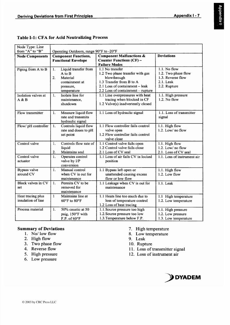
Table
1 1:
CFA for Acid Neutralizing P rocess
Summ ary of Deviations
1
No/ low flow
2.
High flow
3 .
Two phase flow
4
Reverse flow
5. High pressure
6 Low pressure
Node Type: Line
from
A
to B
Node Components
Piping from A to B
Isolation valves at
A & B
Flow transmitter
Flow1 pH controller
Control valve
Control valve
actuator
Bypass valve
around CV
Block valves in CV
set
Heat tracing plus
insulation of line
Process material
7. High temperature
8
Low temperature
9 Leak
10 Rupture
11. Loss o f transmitter signal
12. Loss of instrument air
YADEM
Deviations
1.1. No flow
1.2. Two phase flow
1.3. Reverse flow
2.1. Leak
2.2. Rupture
1.1. High pressure
1.2. No flow
1.1. Loss of transmitter
signal
1.1. High flow
1.2. Low/ no flow
1.1. High flow
1.2. Low/ no flow
2.1. Loss of CV seal
1.1. Loss o f instrument air
1.1. High flow
1.2. Low flow
1.1. Leak
1.1 High temperature
1.2. Low temperature
1.1. High pressure
1.2. Low pressure
1.3. Low temperature
Operating Outdoors, range
Comp onent Functions,
Functional Envelope
1. Liquid transfer from
A to
B
2. Material
containment at
pressure,
temperature
1. Isolate line for
maintenance,
shutdown
1. Me asure liquid flow
rate and transmits
hydraulic signal
1. Con trols liquid flow
rate and do ses to pH
set point
1.
Controls flow rate of
liquid
2. Maintains seal
1 Operates control
valve by IIP
conversion
1. Manual control
when CV is out for
maintenance
1. Permits CV to be
removed for
maintenance
1 Maintains line at
60°F to 80°F
1. 50% caustic at 50
psig, 150°F with
F.P. of 60°F
90°F to -20°F
Component M alfunctions
Counter Functions (CF)
Failure Modes
1.1 No transfer
1.2 Two phase transfer with gas
blowthrough
1.3 Transfer from B to
A
2.1 Loss of containment eak
2.2 Loss of containment upture
1.1 Line overpressures w ith heat
tracing when blocked in CF
1.2 Valve(s) inadvertently closed
1.1 Loss of hydraulic signal
1.1 Flow controller fails control
valve open
1.2 Flow controller fails control
valve close
1.1 Control valve fai ls open
1.2 Control valve fai ls close
2.1 Loss of CV seal
1.1 Loss of air fails CV in locked
position
1.1 Bypass left open or
unattended causing excess
flow or low flow
1.1 Leakage when CV is out for
maintenance
1.1 Heats line too much due to
loss of temperature control
1.2 Loss of heat tracing
1.1 Source pressure too high
1.2.Source pressure too low
1.3.Temperature below F.P.
© 2003 by CRC Prcss LLC

7/17/2019 1909_A001
http://slidepdf.com/reader/full/1909a001 8/12
DerivingDeviationsfrom First Principles
Appendix
Table 1 2: CF for Centrifugal Pump
Node Type
Centrifugal
Pump
ode
Components
pump
impeller
Pump
casing
Pump seal
Seal flush
medium
Pump vent
Pump drain
Pump
coupling
Pump shaft
Motor driver
Motor
control
switch
High load
motor cutout
Power
supply
Baseplate
Process
material
Operating Outdoors, range 90°F to
Component Functions,
Functional Envelope
1. Rotates at constant speed,
fmed location
2. Creates differential head,
imparts energy to liquid
3. Rotates counter-clockwise
4
Creates low pressure at eye
of impeller
1
Material containment
2. Directs liquid through flow
path
3
Withstands centripetal
forces generated
1. Maintains seal between
static and moving parts
1. Lubricates and cools seal
1.
Vents air at pump start
1. Drains pump on shutdown
1. Maintains transmission
between motor and pump
1. Transmits force from motor
to impeller via coupling
1 Generates energy from
electrical supply
2. Maintains constant speed
3
Operates within
temperature range
4
Operates within load range
1. Starts motor
2. Stops motor
1.
Stops motor on over load
1
Supplies power to motor
and in range
1. Maintains alignment
2
Anchors pump
1. Hydrocarbon liquid with
SG of 0 9 and vapor
-20°F
Component Malfunctions
Counter Functions (CF)
Failure Modes
1.1. Overspeeding
1.2. Loss of balance for
impeller
2.1. Discharge pressure too
high
2.2. Discharge pressure too low
3.1. Reverse rotation
4.1. Pump can activate with too
low NPSH
1.1. Casing leaks
1.2 Casing rupture
2.1. Internal recycling, loss of
efficiency
3.1. Cannot withstand high
pressures generated
1.1. Loss of pump seal
eak
1.2. Loss of pump seal
contamination
1.1. Loss of flushing medium
1.1. Vent leaks when operating
1.2. Vent won t vent
1.1. Drain leaks when operating
1.2. Drain won t drain
1.1. Loss of flexibility, vibration
1.1. Misalignment ibration
1.2. Shaft breaks
1.1. Loss of power
2.1. Excessive speed
3.1. Motor overheats
4.1. Motor overloads
1.1. Motor won t start
1.2. Motor won t stop
1.1. Motor overload won t
operate when required
1 1
Excess power to motor
1.2. Loss of power to motor
1 . l . Loss of alignment
vibration
2.1. Loss of anchoring
1.1. Flashing to vapor if eye of
impeller falls below 12 psia
Deviations
1.1. High speed
1.2. Loss of balance,
vibration
2.1. High discharge
pressure
2.2. Low discharge
pressure
3.1. Reverse rotatioil
4.1. Cavitation, NPSH
1.1. Leak
1.2. Rupture
2.1. Loss of efficiency
3.1. High pressure
1.1. Leak
1.2. Contamination
1.1. Loss of flushing
medium
1.1. Leak
1.2. No venting
1.1. Leak
1.2. No draining
1.1. Vibration
1.1. Vibration
1.2. Shaft breaks
1.1. Loss o f power
2.1. High speed
3.1. High motor
temperature
4 1 High motor load
1.1. No motor start
1.2. No motor stopping
1.1. No motor overload trip
1.1. More power
1.2. No power
1.1. Vibration
2.1. Vibration
1.1. Cavitation, NPSH
© 2003 by CRC Prcss LLC
7/17/2019 1909_A001
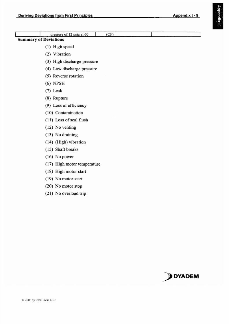
http://slidepdf.com/reader/full/1909a001 9/12
Deriving Deviations from First Principles
Appendix I
9
pressure
of 12
psia at 60
CF)
Summary of eviations
1)
High speed
2) Vibration
3) High discharge pressure
4) Low discharge pressure
5) Reverse rotation
6) NPSH
7) Leak
8) Rupture
9) Loss of efficiency
10) Contamination
1 1) Loss of seal flush
12) No venting
13) No draining
14) High) vibration
15) Shaft breaks
16) No power
17) High motor temperature
1 8) High motor start
19) No motor start
20) No motor stop
21) No overload trip
YADEM
© 2003 by CRC Prcss LLC
7/17/2019 1909_A001
http://slidepdf.com/reader/full/1909a001 10/12
Deriving Deviations from First Principles
Appendix I
10
cid Ne utralizing Process
I _ _ _ _ _
Reaclor a Elevaled Posi l lon
I
FFLU NT
Figure
1 1: P ID
of Acid Neutralizing Proc ess
,
D Y A D E M
© 2003 by CRC Prcss LLC

7/17/2019 1909_A001
http://slidepdf.com/reader/full/1909a001 11/12
Deriving Deviations from First Principles
Appendix 11
entrifugal
Pump
Power
Supply
Pump Discharge
mpeller
Over load) Coupl ing
Shafi
M O T O R 4
Pump Suct ion
Seal
.\
Pump Casing
Figure
1 2:
Schematic Representation of entrifugal Pump
> YADEM
© 2003 by CRC Prcss LLC

7/17/2019 1909_A001
http://slidepdf.com/reader/full/1909a001 12/12
Deriving Deviations from First Principles Appendix
2
SUGGESTED READING Note: URLs current at date of publication)
The 'Traffic
HAZOP'
an approach for identifying deviations from the desired operation
of
driving support systems , by H.M.Jagtinan, (Website)
w\.\~~\~.tbm.ti~delft .nl/~vebstaflcl
enill~ublicatio siTI~h4
stdoc-consort~iim.)actman.pdf
Qualitative Techniques , by R.Pudduck, (Website)
www.ams.~nod.ul~~amslcor~tct~t/~~o~~,i~tgw~eb/pa~~~/~~in~~~ l1 c~1ri:lRIN 1 99.htm
YADEM


