(19) United States (12) Reissued Patent (10) Patent Number ... · which is a continuation of...
24
USOORE4637OE (19) United States (12) Reissued Patent (10) Patent Number: US RE46,370 E Kerofsky (45) Date of Reissued Patent: Apr. 18, 2017 (54) SYSTEMS AND METHODS FOR REDUCED (52) U.S. Cl. BIT DEPTH PROCESSING IN CPC ............ H03M 7/24 (2013.01); H04N 19/136 VIDEO-RELATED DATA WITH FREQUENCY (2014.11) WEIGHTING MATRCES (58) Field of Classification Search USPC ........... 375/240.18, 240.01, E7.028. ET.O93 (71) Applicant: Dolby Laboratories Licensing 375/E7 139 E7 14. E7 21. E7 226. Corporation, San Francisco, CA (US) 75723 (72) Inventor: Louis J. Kerofsky, Camas, WA (US) See application file for complete search history. (73) Assignee: Dolby Laboratories Licensing (56) References Cited Corporation, San Francisco, CA (US) U.S. PATENT DOCUMENTS (21) Appl. No.: 14/207,043 4,894,713 A * 1/1990 Delogne et al. ........... 375,2402 5,230,038 A 7/1993 Fielder et al. (22) Filed: Mar. 12, 2014 (Continued) Related U.S. Patent Documents FOREIGN PATENT DOCUMENTS Reissue of: (64) Patent No.: 7,400,682 CA 2221181 A1 12/1993 Issued: Jul. 15, 2008 GB 2264609 A 9, 1993 Appl. No.: 10/931,558 (Continued) Filed: Aug. 31, 2004 U.S. Applications: OTHER PUBLICATIONS (60) Division of application No. 13/901,316, filed on May 23, 2013, now Pat. No. Re. 44,891, which is a Bontegaard, “H.26L Test Model Long Term No. 7 (TML-7) continuation of application No. 13/301,472, filed on Draft0'. ITU Telecommunications Standardization Sector, Study Nov. 21, 2011, now Pat. No Re 44.319, which is a Group 16. Video Coding Experts Group (VCEG), Document division of application No. 12/837,154, filed on Jul. VCEG-M81. Thirteenth Meeting, Austin, Texas, USA. Apr. 2-4, 15, 2010, now Pat. No. Re 43,091, which is a 200 PP continuation of application No. 12/689,897, filed on (Continued) Jan. 19, 2010, now Pat. No. Re. 42,745, which is an application for the reissue of Pat. No. 7,400,682, Primary Examiner — John M Hotaling which is a continuation of application No. 10/326, (74) Attorney, Agent, or Firm — Fish & Richardson P.C. 459, filed on Dec. 20, 2002, now Pat. No. 7,170,942, which is a continuation of application No. (57) ABSTRACT (Continued) Embodiments of the present invention comprise systems and methods for processing of data related to video wherein (51) Int. Cl. reduced bit depth intermediate calculations are enabled. H03M 7/24 (2006.01) H04N 9/36 (2014.01) 1 Claim, 10 Drawing Sheets c. fic er K supplying 12 Supplying quantizationparameter ap) 4. forming quantization value) s Normalizing quantization valus Forming dequantization walue (x) 1. denormalizing the quantization walue 12
Transcript of (19) United States (12) Reissued Patent (10) Patent Number ... · which is a continuation of...

USOORE4637OE
(19) United States (12) Reissued Patent (10) Patent Number: US RE46,370 E
Kerofsky (45) Date of Reissued Patent: Apr. 18, 2017
(54) SYSTEMS AND METHODS FOR REDUCED (52) U.S. Cl. BIT DEPTH PROCESSING IN CPC ............ H03M 7/24 (2013.01); H04N 19/136 VIDEO-RELATED DATA WITH FREQUENCY (2014.11) WEIGHTING MATRCES (58) Field of Classification Search
USPC ........... 375/240.18, 240.01, E7.028. ET.O93 (71) Applicant: Dolby Laboratories Licensing 375/E7 139 E7 14. E7 21. E7 226.
Corporation, San Francisco, CA (US) 75723 (72) Inventor: Louis J. Kerofsky, Camas, WA (US) See application file for complete search history.
(73) Assignee: Dolby Laboratories Licensing (56) References Cited Corporation, San Francisco, CA (US) U.S. PATENT DOCUMENTS
(21) Appl. No.: 14/207,043 4,894,713 A * 1/1990 Delogne et al. ........... 375,2402 5,230,038 A 7/1993 Fielder et al.
(22) Filed: Mar. 12, 2014 (Continued) Related U.S. Patent Documents FOREIGN PATENT DOCUMENTS
Reissue of: (64) Patent No.: 7,400,682 CA 2221181 A1 12/1993
Issued: Jul. 15, 2008 GB 2264609 A 9, 1993 Appl. No.: 10/931,558 (Continued) Filed: Aug. 31, 2004
U.S. Applications: OTHER PUBLICATIONS (60) Division of application No. 13/901,316, filed on May
23, 2013, now Pat. No. Re. 44,891, which is a Bontegaard, “H.26L Test Model Long Term No. 7 (TML-7) continuation of application No. 13/301,472, filed on Draft0'. ITU Telecommunications Standardization Sector, Study Nov. 21, 2011, now Pat. No Re 44.319, which is a Group 16. Video Coding Experts Group (VCEG), Document division of application No. 12/837,154, filed on Jul. VCEG-M81. Thirteenth Meeting, Austin, Texas, USA. Apr. 2-4, 15, 2010, now Pat. No. Re 43,091, which is a 200 PP continuation of application No. 12/689,897, filed on (Continued) Jan. 19, 2010, now Pat. No. Re. 42,745, which is an application for the reissue of Pat. No. 7,400,682, Primary Examiner — John M Hotaling which is a continuation of application No. 10/326, (74) Attorney, Agent, or Firm — Fish & Richardson P.C. 459, filed on Dec. 20, 2002, now Pat. No. 7,170,942, which is a continuation of application No. (57) ABSTRACT
(Continued) Embodiments of the present invention comprise systems and methods for processing of data related to video wherein
(51) Int. Cl. reduced bit depth intermediate calculations are enabled. H03M 7/24 (2006.01) H04N 9/36 (2014.01) 1 Claim, 10 Drawing Sheets
c. fic er K supplying 12
Supplying quantizationparameter ap) 4.
forming quantization value) s
Normalizing quantization valus
Forming dequantization walue (x) 1.
denormalizing the quantization walue 12

US RE46,370 E Page 2
Related U.S. Application Data
10/139,036, filed on May 2, 2002, now Pat. No. 7,123,655.
(60) Provisional application No. 60/319,018, filed on Nov. 30, 2001, provisional application No. 60/311,436, filed on Aug. 9, 2001.
(56) References Cited
U.S. PATENT DOCUMENTS
5,345,408 A 9/1994 Hoogenboom 5.47 1412 A 11/1995 Shyu 5,479,364 A 12/1995 Jones et al. 5,590,067 A 12/1996 Jones et al. 5,594,678 A 1/1997 Jones et al. 5,596,517 A 1/1997 Jones et al. 5,629,778 A * 5/1997 Reuman ........................ 382,252 5,640,159 A 6, 1997 Furlan et al. 5,748,793 A 5/1998 Sanpei 5,754.457 A 5, 1998 Eitan et al. 5,764,553 A 6/1998 Hong et al. 5,822,003 A 10, 1998 Girod et al. 5,845,112 A 12/1998 Nguyen et al. 5,892,548 A * 4, 1999 Kim ......................... 375,240.04 6,081,552 A * 6/2000 Stevenson et al. ........... 375,240 6, 160,920 A 12/2000 Shyu 6,212.236 B1 4/2001 Nishida et al. 6,721.460 B1 * 4/2004 Haskell et al. ............... 382,268 6,765,963 B2 * 7/2004 Karczewicz et al. ... 375/240.03 6,856.262 B2 2/2005 Mayer et al. 6,876,703 B2 * 4/2005 Ismaeil et al. ........... 375,24O16
2001/0055339 A1* 12, 2001 Choi ........ 2002.0034251 A1* 3, 2002 Suzuki ......... 375,24O16 2002/0118755 A1* 8, 2002 Karczewicz et al. ... 375,240.16 2002fO154693 A1* 10, 2002 Demos et al. ........... 375,240.03 2003/0099291 A1 5/2003 Kerofsky 2003/O112876 A1 6/2003 Kerofsky 2003/O123553 A1 7/2003 Kerofsky 2003/0147463 A1* 8, 2003 Sato et al. ............... 375,240.05 2004, OO13202 A1 1/2004 Lainema 2004/0046754 A1 3/2004 Mayer et al. 2004/0179596 A1* 9/2004 Song et al. .............. 375,240.03
375,240.21
FOREIGN PATENT DOCUMENTS
JP 3-270573. A 12/1991 JP 4-503136. A 6, 1992 JP 4-504.192 A 7, 1992 JP 04-2221.21 8, 1992 JP 4-222121 A 8, 1992 JP 06-046269 2, 1993 JP 5-95.483. A 4f1993 JP O7-O99578 9, 1993 JP 05-307467 11, 1993 JP 5-307467 A 11, 1993 JP 6-46269 A 2, 1994 JP 06-053839 2, 1994 JP 6-53839. A 2, 1994 JP 06-077842 3, 1994 JP 6-77842 A 3, 1994 JP T-99578 A 4f1995 JP 2004-506990 A 3, 2004 KR O172902 3, 1999 KR O172902 B1 3, 1999 WO WO 90,09022 A1 8, 1990 WO WO 90,09064 A1 8, 1990
OTHER PUBLICATIONS
Bontegaard, “H.26L Test Model Long Term No. 8 (TML-8) Draft0'. ITU Telecommunications Standardization Sector, Study Group 16, Video Coding Experts Group (VCEG), Document VCEG-NXX, Apr. 2, 2001 (Generated: Jun. 28, 2001), pp. 1-46.
Extended European Search Report, dated Nov. 4, 2010, for Euro pean Application No. 10179630.8. Extended European Search Report, dated Nov. 4, 2010, for Euro pean Application No. 10179636.5. Hallapuro et al., “Low Complexity (I)DCT, ITU Telecommuni cations Standardization Sector, Study Group 16 Question 6, Video Coding Experts Group (VCEG), 15th Meeting: Pattaya, Thailand, Dec. 4-6, 2001, pp. 1-11. Hallapuro et al., “Low Complexity Transform and Quantization— Part II: Extensions.” Document: JVT-B039, Joint Video Team (JVT) of ISO/IEC MPEG & ITU-T VCEG (ISO/IEC JTC1/SC29/WG 11 and ITU-T SG16 Q.6), 2nd Meeting: Geneva, CH, Jan. 29-Feb. 1. 2002, pp. 1-14. Hallapuro, et al., “Low Complexity Transform and Quantization— Part 1: Basic Implementation.” Joint Video Team (JVT) of ISO/IEC MPEG & ITU-T VCEG (ISO/IEC JCTI/SC29/WG 11 and ITU-T SG16 Q.6), Document: JVT-B038, XP030005037, Jan. 14, 2002, pp. 1-18. Joint Video Team, T. Wiegand (Contact), “Draft ITU-T Recommen dation H.264 (a.k.a. “H.26L')', ITU Telecommunications Stan dardization Sector, Study Group 16 Question 6, Video Coding Experts Group (VCEG), Document: VCEG-P07, 16th Meeting: Fairfax, Virginia, USA, May 6-10, 2002, 141 pages. Kerofsky et al., “Reduced Bit-Depth Quantization.” ITU Tele communications Standardization Sector, Study Group 16 Question 6, Video Coding Experts Group (VCEG), Document VCEG-N20, Fourteenth Meeting: Santa Barbara, CA, USA, Sep. 24-27, 2001, pp. 1-14. Kerofsky, “Modifications to the JVT IDCT", Joint Video Team (JVT) of ISO/IEC MPEG & ITU-T VCEG (ISO/IEC JTC1/SC29/ WG 11 and ITU-T SG16 Q.6), Document: JVT-C25, 3rd Meeting: Fairfax, Virginia, USA, May 6-10, 2002, pp. 1-14. Kerofsky, “Notes on JVT IDCT", Joint Video Team (JVT) of ISO/IEC MPEG & ITU-T VCEG (ISO/IEC JTC1/SC29/WG 11 and ITU-T SG16 Q.6), Document: JVT-C24, 3rd Meeting: Fairfax, Virginia, USA, May 6-10, 2002, pp. 1-8. Klomp et al., “TE 1: Cross-Checking Results of DMVD Proposal JCTVC-B076 (MediaTek Inc.), Joint Collaborative Team on Video Coding (JCT-VC) of ITU-T SG16 WP3 and ISO/IEC JTC1/SC29/ WG11, Document: JCTVC-B119, 2nd Meeting: Geneva, CH, Jul. 21-28, 2010, 1 page. Korean Office Action, dated Jan. 13, 2006, for Korean Application No. 10-2004-700 1865 (English translation only provided). Lepley et al., “Report on Core Experiment CodEff): Integer Quan tization’, Coding of Still Pictures, ISO/IEC JTC1/SC29/WG1 (ITU-T SG8), XPO17205064, Oct. 21, 1998, 5 pages. Liang et al., “A 16-bit Architecture for H.26L, Treating DCT Transforms and Quantization'. ITU Telecommunications Stan dardization Sector, Study Group 16 Question 6, Video Coding Experts Group (VCEG), Document VCEG-M16, XP002332050, Austin, TX, USA, Apr. 2-4, 2001, pp. 1-17. Sun et al., “Global Motion Vector Coding (GMVC), ITU Tele communications Standardization Sector, Study Group 16 Question 6, Video Coding Experts Group (VCEG), Document: VCEG-O20, Fifteenth Meeting: Pattaya, Thailand, Dec. 4-7, 2001, pp. 1-10. “H. 26L Test Model Long Term No. 8(TML-8) Drafto” ITU-T Telecommunication Standarization Sector of ITU, Genevam CH, Apr. 2, 2001, pp. 1-54 XP001089814. Liang J., Tran T., Topiwala P: “a-16-bit architecture for H.26L, treating DCT transforms and quantization' Document VCEG-M16, ITU Elecommuntcations Standardization Sector,Study Group 16 Question 6, Video Coding Experts Group (VCEG), Online Apr. 2, 2001, pp. 1-17, XP002332050 Austin, Texas, USA Rerieved from the Internet ; URL: http://www.ensc.sfu.ca/people/facultyfiel/papers/ H26L -Proposal.doc retrieved on Jun. 8, 2005 abstract Section “Introduction', p. 1 Section 1.2 “Quantization in TML 5.2, pp. 2-3 Section 2.4 “Scaling factors and Quantization', pp. 6-7. Kerofsky L. Lei S.; "Reduced bit- depth quantization' Document VCEG-N20, ITU Telecommunications Standardization Sector, Study Group 16 Question 6: Video Coding Experts Group (VCEG), Online! Sep. 24, 2001, pp. 1-14, XP002332051 Santa Barbara, CA USA Retrieved From thr internet: URL: ftp3.itu.int/av-arch/video site/0109 SAN/vceg-n20. DOC> Retrieved on Jun. 8, 2008. Sec

US RE46,370 E Page 3
(56) References Cited
OTHER PUBLICATIONS
tion “Introduction', pp. 1-2 Section “Proposed Quantization val ues', pp. 3-4 Section “Appendix'. Table 10 and Equations 4.5. Gisele Bontegard, “H.26L Test Model Long Term No. 8 (TML-8) draft0”, document VCEG-M81.ITU-T Video Coding Experts Group (VCEG), Austin, Texas, Apr. 2001.
* cited by examiner

U.S. Patent Apr. 18, 2017 Sheet 1 of 10 US RE46,370 E
Osan 100
Supplying coefficient K 102
Supplying quantization parameter (QP) 104
Forming quantization value (L) 106
Normalizing quantization value 108
Forming dequantization value (XI) 110
Denormalizing the quantization value 112
Figure 1

U.S. Patent Apr. 18, 2017 Sheet 2 of 10 US RE46,370 E
T transformation module Q :duantization module DQ :dequantization module IT inverse transform module FM frame memory MC :motion compensation module
: motion estimation module
Figure 2

U.S. Patent Apr. 18, 2017 Sheet 3 of 10 US RE46,370 E
output decoded 154 image data
input encoded data r
150
l 168
DQ dequantization module T :inverse transform module FM frame memory MC :motion compensation module
Figure 3 '' 164

U.S. Patent Apr. 18, 2017 Sheet 4 of 10 US RE46,370 E
104
image data encoding portion
image data deCOding portion input image Output image
data r 102 Cld 10
storage media 106
Figure 4
114 118
image data image data input image encoding portion decoding portion output image
- r 120 112
Figure 5

U.S. Patent Apr. 18, 2017 Sheet 5 of 10 US RE46,370 E
1st mantissa portion 1st exponential portion processing means processing means
Figure 6
1st mantissa portion 1st shifting portion processing means processing means
Figure 7

U.S. Patent Apr. 18, 2017 Sheet 6 of 10 US RE46,370 E
2nd mantissa portion processing means
2nd exponential portion processing means
Figure 8
2nd mantissa portion 2nd shifting portion processing means processing means
206 de - Figure 9

U.S. Patent Apr. 18, 2017 Sheet 7 of 10 US RE46,370 E
232
A.
C 234
Processing
(Prior Art) 221 FIG. 10
Processing
225
FIG 11

U.S. Patent Apr. 18, 2017 Sheet 8 of 10 US RE46,370 E
Processing
229
F.G. 12
240 228 248
f A.
FIG. 13

U.S. Patent Apr. 18, 2017 Sheet 9 of 10 US RE46,370 E
254
FIG. 14
258 264
256 2 220 C
(Prior Art) 260 FIG. 15
U.S. Patent Apr. 18, 2017 Sheet 10 of 10 US RE46,370 E
280
FIG. 16

US RE46,370 E 1.
SYSTEMIS AND METHODS FOR REDUCED BIT DEPTH PROCESSING IN
VIDEO-RELATED DATA WITH FREQUENCY WEIGHTING MATRCES
Matter enclosed in heavy brackets appears in the original patent but forms no part of this reissue specifica tion; matter printed in italics indicates the additions made by reissue; a claim printed with strikethrough indicates that the claim was canceled, disclaimed, or held invalid by a prior post-patent action or proceeding.
RELATED APPLICATIONS
This application is a continuation of U.S. patent appli cation Ser. No. 10/326,459 entitled, METHODS AND SYS TEMS FOR EFFICIENT VIDEO-RELATED DATA PRO CESSING, invented by Louis Kerofsky, filed Dec. 20, 2002 now U.S. Pat. No. 7,170,942, which is a continuation of U.S. patent application Ser. No. 10/139,036 entitled, METHOD FOR REDUCED BIT-DEPTH QUANTIZATION, invented by Louis Kerofsky, filed May 2, 2002 now U.S. Pat. No. 7,123,655, which claims the benefit of U.S. Provisional Patent Application Ser. No. 60/319,018 entitled, METHODS AND SYSTEMS FOR VIDEO CODING WITH JOINT QUANTIZATION AND NORMALIZATION PROCE DURES, invented by Louis Kerofsky, filed Nov. 30, 2001, and also claims the benefit of U.S. Provisional Patent Application Ser. No. 60/311,436 entitled, REDUCED BIT DEPTH QUANTIZATION, invented by Louis Kerofsky, filed Aug. 9, 2001.
Several reissue applications have been filed for U.S. Pat. No. 7,400,682. These are: patent application Ser: No. 14/207,043, filed on Mar 12, 2014 (this application), patent application Ser: No. 13/901,316, filed May 23, 2013, now issued as U.S. Pat. No. Re. 44,891; patent application Ser: No. 13/301,526, filed Nov. 21, 2011, now issued as U.S. Pat. No. Re. 44, 138; patent application Ser: No. 13/301,502, filed Nov. 21, 2011, now issued as U.S. Pat. No. Re. 44, 234, patent application Ser: No. 13/301,472, filed Nov. 21, 2011, now issued as U.S. Pat. No. Re. 44,319 patent application Ser: No. 13/301,430 filed Nov. 21, 2011, now issued as U.S. Pat. No. Re. 44, 285, patent application Ser: No. 1 2/837, 154, filed Jul. 15, 2010, now issued as U.S. Pat. No. Re. 43,091, patent application Ser: No. 1 2/689,897, filed Jan. 19, 2010, now issued as U.S. Pat. No. Re 42,745, patent application Ser: No. 15/400, III, filed Jan. 6, 2017; and patent applica tion Ser: No. 15/400, 121, filed Jan. 6, 2017.
5
10
15
25
30
35
40
45
This application is a divisional reissue application of 50 patent application Ser: No. 13/901,316, filed May 23, 2013, now issued as U.S. Pat. No. Re. 44,891, and is a reissue of U.S. Pat. No. 7,400,682, patent application Ser: No. 13/901, 316 is a continuation reissue application of patent applica tion Ser: No. 13/301,472, filed Nov. 21, 2011, now issued as U.S. Pat. No. Re. 44,319, and is a reissue of U.S. Pat. No. 7,400,682. Patent application Ser: No. 13/301,472 is a divisional reissue application of patent application Ser: No. 12/837, 154, filed Jul 15, 2010, now issued as U.S. Pat. No. Re. 43,091, and is a reissue of U.S. Pat. No. 7,400,682. Patent application Ser: No. 12/837, 154 is a continuation reissue application of patent application Ser: No. 1 2/689, 897, filed Jan. 19, 2010, now issued as U.S. Pat. No. Re. 42,745 and is a reissue of U.S. Pat. No. 7,400.682. Patent application Ser: No. 1 2/689,897 is a reissue of U.S. Pat. No. 7,400,682, which was filed as patent application Ser: No. 10/931,558, on Aug. 31, 2004. Patent application Ser: No.
55
60
65
2 10/931,558 is a continuation of patent application Ser: No. 10/326,459 filed on Dec. 20, 2002, now issued as U.S. Pat. No. 7, 170,942, which is a continuation of patent application Ser: No. 10/139,036, filed May 2, 2002, now issued as U.S. Pat. No. 7, 123,655. Patent application Ser: No. 10/139,036 claims priority from provisional application No. 60/319,018, filed Nov. 30, 2001, and also from provisional application No. 60/3 II,436, filed Aug. 9, 2001.
BACKGROUND OF THE INVENTION
1. Field of the Invention This invention generally relates to video compression
techniques and, more particularly, to a method for reducing the bit size required in the computation of video coding transformations.
2. Description of the Related Art A video information format provides visual information
Suitable to activate a television screen, or store on a video tape. Generally, video data is organized in a hierarchical order. A video sequence is divided into group of frames, and each group can be composed of a series of single frames. Each frame is roughly equivalent to a still picture, with the still pictures being updated often enough to simulate a presentation of continuous motion. A frame is further divided into slices, or horizontal sections which helps sys tem design of error resilience. Each slice is coded indepen dently so that errors do not propagate across slices. A slice consists of macroblocks. In H.26P and Motion Picture Experts Group (MPEG)-X standards, a macroblock is made up of 16x16 luma pixels and a corresponding set of chroma pixels, depending on the video format. A macroblock always has an integer number of blocks, with the 8x8 pixel matrix being the Smallest coding unit.
Video compression is a critical component for any appli cation which requires transmission or storage of video data. Compression techniques compensate for motion by reusing stored information in different areas of the frame (temporal redundancy). Compression also occurs by transforming data in the spatial domain to the frequency domain. Hybrid digital video compression, exploiting temporal redundancy by motion compensation and spatial redundancy by trans formation, such as Discrete Cosine Transform (DCT), has been adapted in H.26P and MPEG-X international standards as the basis. As stated in U.S. Pat. No. 6,317,767 (Wang), DCT and
inverse discrete cosine transform (IDCT) are widely used operations in the signal processing of image data. Both are used, for example, in the international standards for moving picture video compression put forth by the MPEG. DCT has certain properties that produce simplified and efficient cod ing models. When applied to a matrix of pixel data, the DCT is a method of decomposing a block of data into a weighted sum of spatial frequencies, or DCT coefficients. Conversely, the IDCT is used to transform a matrix of DCT coefficients back to pixel data.
Digital video (DV) codecs are one example of a device using a DCT-based data compression method. In the block ing stage, the image frame is divided into N by N blocks of pixel information including, for example, brightness and color data for each pixel. A common block size is eight pixels horizontally by eight pixels vertically. The pixel blocks are then “shuffled so that several blocks from different portions of the image are grouped together. Shuf fling enhances the uniformity of image quality.
Different fields are recorded at different time incidents. For each block of pixel data, a motion detector looks for the

US RE46,370 E 3
difference between two fields of a frame. The motion information is sent to the next processing stage. In the next stage, pixel information is transformed using a DCT. An 8-8 DCT, for example, takes eight inputs and returns eight outputs in both vertical and horizontal directions. The result ing DCT coefficients are then weighted by multiplying each block of DCT coefficients by weighting constants.
The weighted DCT coefficients are quantized in the next stage. Quantization rounds off each DCT coefficient within a certain range of values to be the same number. Quantizing tends to set the higher frequency components of the fre quency matrix to Zero, resulting in much less data to be stored. Since the human eye is most sensitive to lower frequencies, however, very little perceptible image quality is lost by this stage. The quantization stage includes converting the two-di
mensional matrix of quantized coefficients to a one-dimen sional linear stream of data by reading the matrix values in a ZigZag pattern and dividing the one-dimensional linear stream of quantized coefficients into segments, where each segment consists of a string of Zero coefficients followed by a non-Zero quantized coefficient. Variable length coding (VLC) then is performed by transforming each segment, consisting of the number of Zero coefficients and the ampli tude of the non-Zero coefficient in the segment, into a variable length codeword. Finally, a framing process packs every 30 blocks of variable length coded quantized coeffi cients into five fixed-length synchronization blocks.
Decoding is essentially the reverse of the encoding pro cess described above. The digital stream is first deframed. Variable length decoding (VLD) then unpacks the data so that it may be restored to the individual coefficients. After inverse quantizing the coefficients, inverse weighting and an inverse discrete cosine transform (IDCT) are applied to the result. The inverse weights are the multiplicative inverses of the weights that were applied in the encoding process. The output of the inverse weighting function is then processed by the IDCT. Much work has been done studying means of reducing the
complexity in the calculation of DCT and IDCT. Algorithms that compute two-dimensional IDCTs are called “type I algorithms. Type I algorithms are easy to implement on a parallel machine, that is, a computer formed of a plurality of processors operating simultaneously in parallel. For example, when using N parallel processors to perform a matrix multiplication on NXN matrices, N column multiplies can be simultaneously performed. Additionally, a parallel machine can be designed so as to contain special hardware or software instructions for performing fast matrix transpo sition. One disadvantage of type I algorithms is that more
multiplications are needed. The computation sequence of type I algorithms involves two matrix multiplies separated by a matrix transposition which, if N=4, for example, requires 64 additions and 48 multiplications for a total number of 112 instructions. It is well known by those skilled in the art that multiplications are very time-consuming for processors to perform and that system performance is often optimized by reducing the number of multiplications per formed. A two-dimensional IDCT can also be obtained by con
verting the transpose of the input matrix into a one-dimen sional vector using an L function. Next, the tensor product of constant a matrix is obtained. The tensor product is then multiplied by the one-dimensional vector L. The result is converted back into an NXN matrix using the M function. Assuming again that N=4, the total number of instructions
5
10
15
25
30
35
40
45
50
55
60
65
4 used by this computational sequence is 92 instructions (68 additions and 24 multiplications). Algorithms that perform two-dimensional IDCTs using this computational sequence are called “type II algorithms. In type II algorithms, the two constant matrices are grouped together and performed as one operation. The advantage of type II algorithms is that they typically require fewer instructions (92 versus 112) and, in particular, fewer costly multiplications (24 versus 48). Type II algorithms, however, are very difficult to implement efficiently on a parallel machine. Type II algorithms tend to reorder the data very frequently and reordering data on a parallel machine is very time-intensive.
There exist numerous type I and type II algorithms for implementing IDCTs, however, dequantization has been treated as an independent step depending upon DCT and IDCT calculations. Efforts to provide bit exact DCT and IDCT definitions have led to the development of efficient integer transforms. These integer transforms typically increase the dynamic range of the calculations. As a result, the implementation of these algorithms requires processing and storing data that consists of more than 16 bits.
It would be advantageous if intermediate stage quantized coefficients could be limited to a maximum size in transform processes.
It would be advantageous if a quantization process could be developed that was useful for 16-bit processors.
It would be advantageous if a decoder implementation, dequantization, and inverse transformation could be imple mented efficiently with a 16-bit processor. Likewise, it would be advantageous if the multiplication could be per formed with no more than 16 bits, and if memory access required no more than 16 bits.
SUMMARY OF THE INVENTION
The present invention is an improved process for video compression. Typical video coding algorithms predict one frame from previously coded frames. The error is subjected to a transform and the resulting values are quantized. The quantizer controls the degree of compression. The quantizer controls the amount of information used to represent the Video and the quality of the reconstruction. The problem is the interaction of the transform and
quantization in video coding. In the past the transform and quantizer have been designed independently. The transform, typically the discrete cosine transform, is normalized. The result of the transform is quantized in standard ways using scalar or vector quantization. In prior work, MPEG-1, MPEG-2, MPEG-4, H.261, H.263, the definition of the inverse transform has not been bit exact. This allows the implementer some freedom to select a transform algorithm suitable for their platform. A drawback of this approach is the potential for encoder/decoder mismatch damaging the prediction loop. To solve this mismatch problem portions of the image are periodically coded without prediction. Current work, for example H.26L, has focused on using integer transforms that allow bit exact definition. Integer transforms may not normalized. The transform is designed so that a final shift can be used to normalize the results of the calculation rather than intermediate divisions. Quantization also requires division. H.26L provides an example of how these integer transforms are used along with quantization.
In H.26L Test Model Long-term 8, normalization is combined with quantization and implemented via integer multiplications and shifts following forward transform and quantization and following dequantization and inverse trans form. H.26L TML uses two arrays of integers A(QP) and

US RE46,370 E 5
B(QP) indexed by quantization parameter (QP), see Table 1. These values are constrained by the relation shown below in Equation 1.
TABLE 1.
TML quantization parameters
QP Azat (QP) B1 (QP)
O 62O 3881 1 553 4351 2 492 4890 3 439 S481 4 391 6154 5 348 6914 6 310 7761 7 276 8718 8 246 9781 9 219 10987 10 195 12339 11 174 13828 12 155 15523 13 138 17435 14 123 19561 15 110 21873 16 98 24552 17 87 27656 18 78 3O847 19 69 34870 2O 62 38807 21 55 43747 22 49 491O3 23 44 S4683 24 39 61694 25 35 68745 26 31 77615 27 27 891.13 28 24 10O2S3 29 22 109366 30 19 126635 31 17 141533
Equation 1 Joint Normalization/Quantization Relation
Normalization and quantization are performed simultane ously using these integers and divisions by powers of 2. Transform coding in H.26L uses a 4x4 block size and an integer transform matrix T. Equation 2. For a 4x4 block X, the transform coefficients K are calculated as in Equation 3. From the transform coefficients, the quantization levels, L. are calculated by integer multiplication. At the decoder the levels are used to calculate a new set of coefficients, K'. Additional integer matrix transforms followed by a shift are used to calculate the reconstructed values X'. The encoder is allowed freedom in calculation and rounding of the forward transform. Both encoder and decoder must compute exactly the same answer for the inverse calculations.
Equation 2 H.26L Test Model 8 Transform Matrix
13 13 13 13
17 7 - 7 - 17 T =
13 - 13 - 13 13
7 - 17 17 -7
10
15
25
30
35
40
45
50
55
60
65
6 Equation 3 TML DCT LUMA and iDCT LUMA
Y=T.X
K=Y.T.
Where the intermediate result Y is the result of a one dimensional transform and the intermediate result Y is the result of a one dimensional inverse transform.
The dynamic range required during these calculations can be determined. The primary application involves 9-bit input, 8 bits plus sign, the dynamic range required by intermediate registers and memory accesses is presented in Table 2.
TABLE 2
Dynamic range of TML transform and inverse transform (bits
9-bit input LUMA Transform Inverse Transform
Register 30 27 Memory 21 26
To maintain bit-exact definitions and incorporate quanti Zation, the dynamic range of intermediate results can be large since division operations are postponed. The present invention combines quantization and normalization, to eliminate the growth of dynamic range of intermediate results. With the present invention the advantages of bit exact inverse transform and quantization definitions are kept, while controlling the bit depth required for these calculations. Reducing the required bit depth reduces the complexity required of a hardware implementation and enables efficient use of single instruction multiple data (SIMD) operations, such as the Intel MMX instruction set.
Accordingly, a method is provided for the quantization of a coefficient. The method comprises: receiving a coefficient K; receiving a quantization parameter (QP); forming a quantization value (L) from the coefficient K using a man tissa portion (Am(QP)) and an exponential portion (x'). Typically, the value of X is 2.
In some aspects of the method, forming a quantization value (L) from the coefficient K includes:
L = K: A(QP)
= K: Am(QP): (2.2).
In other aspects, the method further comprises: normal izing the quantization value by 2' as follows:
= K. Am(OP)/2 (NA2P).
In some aspects, forming a quantization value includes forming a set of recursive quantization factors with a period P, where A(QP+P)=A(QP)/x. Therefore, forming a set of

US RE46,370 E 7
recursive quantization factors includes forming recursive mantissa factors, where Am(OP)=Am(OP modP). Likewise, forming a set of recursive quantization factors includes forming recursive exponential factors, where Ae(QP)=Ae (QP mod P)-QP/P. More specifically, receiving a coefficient K includes
receiving a coefficient matrix Kii. Then, forming a quan tization value (L) from the coefficient matrix Kij includes forming a quantization value matrix (Lij) using a man tissa portion matrix (Am(OP)ij) and an exponential por tion matrix (x (9 FIU).
Likewise, forming a quantization value matrix (Lij) using a mantissa portion matrix (Am(OP)ij) and an exponential portion matrix (x') includes, for each particular value of QP, every element in the exponential portion matrix being the same value. Every element in the exponential portion matrix is the same value for a period (P) of QP values, where Ae(QP)=Ae(P*(QP/P)).
Additional details of the above-described method, includ ing a method for forming a dequantization value (X 1), from the quantization value, using a mantissa portion (Brm(QP)) and an exponential portion (x'), are provided below.
BRIEF DESCRIPTION OF THE DRAWINGS
FIG. 1 is a flowchart illustrating the present invention method for the quantization of a coefficient.
FIG. 2 is a diagram showing embodiments of the present invention comprising systems and methods for video encod ing wherein a quantization parameter may be established based on user inputs;
FIG. 3 is a diagram showing embodiments of the present invention comprising systems and methods for video decod ing:
FIG. 4 is diagram showing embodiments of the present invention comprising storing encoder output on a computer readable storage media;
FIG. 5 is a diagram showing embodiments of the present invention comprising sending encoder output over a net work;
FIG. 6 is a diagram showing embodiments of quantization methods and apparatuses of the present invention compris ing a first mantissa portion processing means and a first exponential portion processing means;
FIG. 7 is a diagram showing embodiments of quantization methods and apparatuses of the present invention compris ing a first mantissa portion processing means and a first shifting portion processing means;
FIG. 8 is a diagram showing embodiments of dequanti Zation methods and apparatuses of the present invention comprising a second mantissa portion processing means and a second exponential portion processing means;
FIG. 9 is a diagram showing embodiments of dequanti Zation methods and apparatuses of the present invention comprising a second mantissa portion processing means and a second shifting portion processing means;
FIG. 10 is diagram showing prior art methods comprising dequantization, inverse transformation, and normalization (Prior Art);
FIG. 11 is a diagram showing embodiments of the present invention comprising factorization of an equivalent of a dequantization Scaling factor;
FIG. 12 is a diagram showing embodiments of the present invention comprising factorization thereby achieving a reduction in bit depth for inverse transformation calculations and reduce memory requirements for dequantization param eter storage;
10
15
25
30
35
40
45
50
55
60
65
8 FIG. 13 is a diagram showing embodiments of the present
invention comprising a normalization process independent of quantization parameter (QP);
FIG. 14 is diagram showing embodiments of the present invention comprising frequency dependent quantization;
FIG. 15 is a diagram showing prior art methods compris ing quantization (Prior Art); and
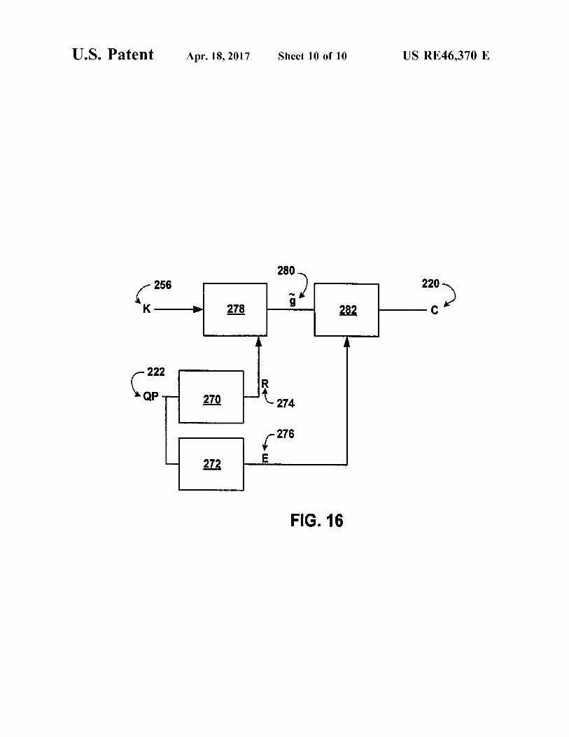
FIG. 16 is a diagram showing embodiments of the present invention comprising factorization of an equivalent of a quantization scaling factor.
DETAILED DESCRIPTION OF THE PREFERRED EMBODIMENTS
The dynamic range requirements of the combined trans form and quantization is reduced by factoring the quantiza tion parameters A(QP) and B(QP) into a mantissa and exponent terms as shown in Equation 4. With this structure, only the precision due to the mantissa term needs to be preserved during calculation. The exponent term can be included in the final normalization shift. This is illustrated in the sample calculation Equation 5.
Equation 4 Structure of Quantization Parameters
foro
Equation 5 Reduced Bit Depth LUMA Transform
aaratissa
To illustrate the present invention, a set of quantization parameters is presented that reduce the dynamic range requirement of an H.26L decoder to 16-bit memory access. The memory access of the inverse transform is reduced to 16 bits. Values for Amantissa' Aexponent Bmantissa Beyponent A, B, are defined for QP-0-5 as shown in Table 3. Additional values are determined by recursion, as shown in Equation 6. The structure of these values makes it possible to generate new quantization values in addition to those specified.
TABLE 3
Quantization values O-5 for TML
QP Amantissa Aexponent Binantissa Bexponent Aproposed Boroposed O 5 7 235 4 640 3760 1 9 6 261 4 576 4176 2 127 2 37 7 SO8 4736 3 114 2 16S 3 456 S280 4 25 4 47 7 4OO 6O16 5 87 2 27 8 348 6912

US RE46,370 E 9
Equation 6 Recursion Relations
Amantissa (QP+6) Amantissa (QP)
Banissa (QP+6)-Bantissa (QP)
Aeronent(QP+6). Aer one (QP)-l
Be, one (QP+6)-Bee, one (QP)+1 Using the defined parameters, the transform calculations
can be modified to reduce the dynamic range as shown in Equation 5. Note how only the mantissa values contribute to the growth of dynamic range. The exponent factors are incorporated into the final normalization and do not impact the dynamic range of intermediate results.
With these values and computational method, the dynamic range at the decoder is reduced so only 16-bit memory access is needed as seen in Table 4.
TABLE 4
Dynamic range with low-bit depth quantization (OP > 6
8-bit LUMA Transform LUMA Inverse Transform
Register 28 24 Memory 21 16
Several refinements can be applied to the joint quantiza tion/normalization procedure described above. The general technique of factoring the parameters into a mantissa and exponent forms the basis of these refinements. The discussion above assumes all basis functions of the
transform have an equal norm and are quantized identically. Some integer transforms have the property that different basis functions have different norms. The present invention technique has been generalized to support transforms having different norms by replacing the scalars A(QP) and B(QP) above by matrices A(QP)ij and B(QP)ij. These parameters are linked by a normalization relation of the form shown below, Equation 7, which is more general than the single relation shown in Equation 1.
Equation 7 Joint Quantization/Normalization of Matrices
Following the method previously described, each element of each matrix is factored into a mantissa and an exponent term as illustrated in the equations below, Equation 8.
Equation 8 Factorization of Matrix Parameters
A(QP)ii)=A(QP)ij-2 exponent OFD)
A large number of parameters are required to describe these quantization and dequantization parameters. Several structural relations can be used to reduce the number of free parameters. The quantizer growth is designed so that the values of A are halved after each period Pat the same time the values of B are doubled maintaining the normalization relation. Additionally, the values of A(QP)ij and B(QP) ili are independent of i,j and (QP) in the range O.P-1. This structure is summarized by structural
10
15
25
30
35
40
45
50
55
60
65
10 equations, Equation 9. With this structure there are only two parameters Aexponent.0 and Beyponen.0.
Equation 9 Structure of Exponent Terms
Aer one (QP) ill-Aeronen (O-QPP
Bee (QP)ij-Be, eIO-QPP A structure is also defined for the mantissa values. For
each index pair (i,j), the mantissa values are periodic with period P. This is summarized by the structural equation, Equation 10. With this structure, there are P independent matrices for A, and P independent matrices for B. reducing memory requirements and adding struc ture to the calculations.
Equation 10 Structure of Mantissa Terms
Aris (QP)ij-Alis (QP% P)ij
Bissa (QP)ij-Bissa (QP% P)ij
The inverse transform may include integer division that requires rounding. In cases of interest, the division is by a power of 2. The rounding error is reduced by designing the dequantization factors to be multiples of the same power of 2, giving no remainder following division.
Dequantization using the mantissa Values B, (QP) gives dequantized values that are normalized differently depending upon QP. This must be compensated for follow ing the inverse transform. A form of this calculation is shown in Equation 11.
Equation 11 Normalization of Inverse Transform I
Ki-B(QP 96 P)i-Leveli
To eliminate the need for the inverse transform to com pensate for this normalization difference, the dequantization operation is defined so that all dequantized values have the same normalization. The form of this calculation is shown in Equation 12.
Equation 12 Normalization of Inverse Transform II
Ki-B(QP 96 P)i-Leveli
An example follows that illustrates the present invention use of quantization matrices. The forward and inverse trans forms defined in Equation 13 need a quantization matrix rather than a single Scalar quantization value. Sample quan tization and dequantization parameters are given. Equation 14 and 16, together with related calculations, illustrate the use of this invention. This example uses a period P=6.
Equation 13 transforms
1 1 1 1
2 1 - 1 -2
1 - 1 - 1 1
1 -2 2 - 1
Tforward =

US RE46,370 E
-continued 2 2 2 1
2 1 -2 -2 Treverse =
2 -2 -2 2
2 - 1 2 - 1
Equation 14 quantization parameters
Q(m)ij = Mo for (i, j) = (0, 0), (0,2), (2,0), (2, 2)
Q(m)ij = M1 for (i, j) = (1, 1), (1,3), (3, 1), (3, 3)
Q(m)ij = M2 otherwise
21844 8388 13108
8724 7625 11650
6384 6989 10486
T 14564 5992 9532 3107 5243 8066
916 4660 7490
Equation 16 Dequantization parameters
R(m)ij = So for (i, j) = {(0, 0), (0,2), (2,0), (2, 2)}
R(m)ij = S, for (i, j) = {(1, 1), (1,3), (3, 1), (3, 3)}
R(m)ij = S2 otherwise
6 10 8
7 11 9
8 12 10 S =
9 14 11
10 16 13
11 18 14
The description of the forward transformation and for ward quantization, Equation 18, are given below assuming input is in X, quantization parameter QP.
Equation 17 Forward Transform
KToward XTorvard'
Equation 18 Forward Quantization
period=QP/6
phase=QP-6 period
Leveli)=(Q(phase)ij-Kii)/277
The description of dequantization, inverse transform, and normalization for this example is given below, Equation 19 and 20.
Equation 19 Dequantization
period=QP/6
phase=QP-6 period
Kill=R(phase)ill-Level ill-2P
10
15
25
30
35
40
45
50
55
60
65
12 Equation 20 IDCT and Normalization
reese eese
FIG. 1 is a flowchart illustrating the present invention method for the quantization of a coefficient. Although this method is depicted as a sequence of numbered steps for clarity, no order should be inferred from the numbering unless explicitly stated. It should be understood that some of these steps may be skipped, performed in parallel, or per formed without the requirement of maintaining a strict order of sequence. The methods start at Step 100. Step 102 Supplies a coefficient K. Step 104 Supplies a quantization parameter (QP). Step 106 forms a quantization value (L) from the coefficient K using a mantissa portion (Am(OP)) and an exponential portion (x'). Typically, the expo nential portion (x') includes x being the value 2.
In some aspects of the method, forming a quantization value (L) from the coefficient K using a mantissa portion (Am(QP)) and an exponential portion (x) in Step 106 includes:
= K: Am(QP): (2.2).
Some aspects of the method include a further step. Step 108 normalizes the quantization value by 2N as follows:
= K. Am(OP)/2 (NA2P).
In other aspects, forming a quantization value in Step 106 includes forming a set of recursive quantization factors with a period P. where A(QP+P)=A(QP)/x. Likewise, forming a set of recursive quantization factors includes forming recur sive mantissa factors, where Am(OP)=Am(OP mod P). Then, forming a set of recursive quantization factors includes forming recursive exponential factors, where Ae(QP)=Ae(QP mod P)-QP/P.
In some aspects, forming a quantization value includes forming a set of recursive quantization factors with a period P, where A(QP+P)=A(QP)/2. In other aspects, forming a set of recursive quantization factors includes forming recursive mantissa factors, where P=6. Likewise, forming a set of recursive quantization factors includes forming recursive exponential factors, where P=6.
In some aspects of the method, receiving a coefficient K in Step 102 includes receiving a coefficient matrix Ki. Then, forming a quantization value (L) from the coefficient matrix Kii using a mantissa portion (Am(OP) and an exponential portion (x') in Step 106 includes forming a quantization value matrix (Lij) using a mantissa portion matrix (Am (QP)ij) and an exponential portion matrix (x'). Likewise, forming a quantization value matrix (Lij) using a mantissa portion matrix (Am(OP)ij) and an exponential portion matrix (x2)) includes, for each particular value of QP, every element in the exponential portion matrix being the same value. Typically, every ele ment in the exponential portion matrix is the same value for a period (P) of QP values, where Ae(QP)=Ae(P*(QP/P)).

US RE46,370 E 13
Some aspects of the method include a further step. Step 110 forms adequantization value (X 1) from the quantization value, using a mantissa portion (Brm(QP)) and an exponen tial portion (XBe(QP)). Again, the exponential portion (x2)) typically includes x being the value 2.
In some aspects of the method, forming a dequantization value (X 1) from the quantization value, using a mantissa portion (Bm(QP)) and an exponential portion (2’’) includes:
= Lt. Bm(QP): (29)).
Other aspects of the method include a further step, Step 112, of denormalizing the quantization value by 2” as follows:
In some aspects, forming a dequantization value in Step 110 includes forming a set of recursive dequantization factors with a period P. where B(QP+P)=x*B(QP). Then, forming a set of recursive dequantization factors includes forming recursive mantissa factors, where Bm(QP)=Bm(QP mod P). Further, forming a set of recursive dequantization factors includes forming recursive exponential factors, where Be(QP)=Be(QP mod P)+QP/P.
In some aspects, forming a set of recursive quantization factors with a period P includes the value of X being equal to 2, and forming recursive mantissa factors includes the value of P being equal to 6. Then, forming a set of recursive dequantization factors includes forming recursive exponen tial factors, where Be(QP)=Be(QP mod P)+QP/P.
In some aspects of the method, forming a dequantization value (X 1), from the quantization value, using a mantissa portion (Bm(QP)) and an exponential portion (x') in Step 110 includes forming a dequantization value matrix (X1i) using a mantissa portion matrix (Brm(QP)ii) and an exponential portion matrix (x'). Likewise, forming a dequantization value matrix (X1 ii) using a mantissa portion matrix (Brm(QP)ij) and an exponential portion matrix (x') includes, for each particular value of QP, every element in the exponential portion matrix being the same value. In some aspects, every element in the exponential portion matrix is the same value for a period (P) of QP values, where Be(QP)=Be(P*(QP/P)).
Another aspect of the invention includes a method for the dequantization of a coefficient. However, the process is essentially the same as Steps 110 and 112 above, and is not repeated in the interest of brevity. A method for the quantization of a coefficient has been
presented. An example is given illustrating a combined dequantization and normalization procedure applied to the H.26L Video coding standard with a goal of reducing the bit-depth required at the decoder to 16 bits. The present invention concepts can also be used to meet other design goals within H.26L. In general, this invention has applica tion to the combination of normalization and quantization calculations.
Embodiments of the present invention may be imple mented as hardware, firmware, Software and other imple
10
15
25
30
35
40
45
50
55
60
65
14 mentations. Some embodiments may be implemented on general purpose computing devices or on computing devices specifically designed for implementation of these embodi ments. Some embodiments may be stored in memory as a means of storing the embodiment or for the purpose of executing the embodiment on a computing device. Some embodiments of the present invention comprise
systems and methods for video encoding, as shown in FIG. 2. In these embodiments, image data 130 is subtracted from 132 with data representing prior video frames 145 resulting in a differential image 133, which is sent to a transform module 134. Transform module 134 may use DCT or other transform methods to transform the image. Generally, the result of the transform process will be coefficients (K), which are then sent to a quantization module 136 for quantization.
Quantization module 136 may have other inputs, such as user inputs 131 for establishing quantization parameters (QPs) and for other input. Quantization module 136 may use the transformation coefficients and the quantization param eters to determine quantization levels (L) in the video image. Quantization module 136 may use methods employing a mantissa portion and an exponential portion, however, other quantization methods may also be employed in the quanti zation modules 136 of embodiments of the present inven tion. These quantization levels 135 and quantization param eters 133 are output to a coding module 138 as well as a dequantization module (DQ) 140.
Output to the coding module 138 is encoded and trans mitted outside the encoder for immediate decoding or Stor age. Coding module 138 may use variable length coding (VLC) in its coding processes. Coding module 138 may use arithmetic coding in its coding process.
Output from quantization module 136 is also received at dequantization module 140 to begin reconstruction of the image. This is done to keep an accurate accounting of prior frames. Dequantization module 140 performs a process with essentially the reverse effect as quantization module 136. Quantization levels or values (L) are dequantized yielding transform coefficients. Dequantization modules 140 may use methods employing a mantissa portion and an exponential portion as described herein. The transform coefficients output from dequantization
module 140 are sent to an inverse transformation (IT) module 142 where they are inverse transformed to a differ ential image 141. This differential image 141 is then com bined with data from prior image frames 145 to form a video frame 149 that may be input to a frame memory 146 for reference to Succeeding frames.
Video frame 149 may also serve as input to a motion estimation module 147, which also receives input image data 130. These inputs may be used to predict image similarities and help compress image data. Output from motion estimation module 147 is sent to motion compensa tion module 148 and combined with output data from coding module 138, which is sent out for later decoding and eventual image viewing. Motion compensation module 148 uses the predicted
image data to reduce frame data requirements; its output is subtracted from input image data 130. Some embodiments of the present invention comprise
systems and methods for video decoding, as shown in FIG. 3. A decoder of embodiments of the present invention may receive encoded image data 150 to a decoder module 152. Encoded image data 150 may comprise data that has been encoded by an encoder 100 such as that described with reference to FIG. 2.

US RE46,370 E 15
Decoder module 152 may employ variable length decod ing methods if they were used in the encoding process. Other decoding methods may also be used as dictated by the type of encoded data 150. Decoding module 152 performs essen tially the reverse process as coding module 138. Output from decoding module 152 may comprise quantization param eters 156 and quantization values 154. Other output may comprise motion estimation data and image prediction data that may be sent directly to a motion compensation module 166.
Typically, quantization parameters 156 and quantization values 154 are output to adequantization module 158, where quantization values are converted back to transform coeffi cients. These coefficients are then sent to an inverse trans formation module 160 for conversion back to spatial domain image data 161. The motion compensation unit 166 uses motion vector
data and the frame memory 164 to construct a reference image 165.
Image data 161 represents a differential image that must be combined 162 with prior image data 165 to form a video frame 163. This video frame 163 is output 168 for further processing, display or other purposes and may be stored in frame memory 164 and used for reference with subsequent frames.
In some embodiments of the present invention, as illus trated in FIG. 4, image data 102 may be sent to an encoder or encoding portion 104 for the various transformation, quantization, encoding and other procedures typical of video encoding as described above for some embodiments of the present invention. Output from the encoder may then be stored on any computer-readable storage media 106. Storage media 106 may act as a short-term buffer or as a long-term storage device. When desired, encoded video data may be read from
storage media 106 and decoded by a decoder or decoding portion 108 for output 110 to a display or other device.
In some embodiments of the present invention, as illus trated in FIG. 5, image data 112 may be sent to an encoder or encoding portion 114 for the various transformation, quantization, encoding and other procedures typical of video encoding as described above for some embodiments of the present invention. Output from the encoder may then be sent over a network, such as a LAN, WAN or the Internet 116. A storage device Such as storage media 106 may be part of a network. Encoded video data may be received and decoded by a decoder or decoding portion 118, which also commu nicates with network 116. Decoder 118 may then decode the data for local consumption 120.
In some embodiments of the present invention, as illus trated in FIG. 6, a quantization method or apparatus com prises a mantissa portion 172 and an exponential portion 174. Quantization parameters 176 are input to both portions 172 & 174. A coefficient K 170 is input to the mantissa portion 172 where it is modified using the quantization parameter and other values as explained above. The result of this operation is combined with the result produced in the exponential portion using the quantization parameter thereby producing a quantization level or value L 178.
In some embodiments of the present invention, as illus trated in FIG. 7, a quantization method or apparatus com prises a mantissa portion 182 and a shifting portion 184. Quantization parameters 186 are input to both portions 182 & 184. A coefficient, K 180 is input to the mantissa portion 182 where it is modified using the quantization parameter and other values as explained above. The result of this
10
15
25
30
35
40
45
50
55
60
65
16 operation is further processed in the shifting portion using the quantization parameter thereby producing a quantization level or value, L 188. Some embodiments of the present invention, as illustrated
in FIG. 8, comprise a dequantization method or apparatus with a mantissa portion 192 and an exponential portion 194. Quantization parameters 196 are input to both portions 192 & 194. A quantization value, L190 is input to the mantissa portion 192 where it is modified using the quantization parameter and other values as explained above. The result of this operation is further processed in the exponential portion using the quantization parameter thereby producing a coef ficient, X1 198. Some embodiments of the present invention, as illustrated
in FIG. 9, comprise a dequantization method or apparatus with a mantissa portion 202 and a shifting portion 204. Quantization parameters 206 are input to both portions 202 & 204. A quantization value, L 200 is input to the mantissa portion 202 where it is modified using the quantization parameter and other values as explained above. The result of this operation is further processed in the exponential portion using the quantization parameter thereby producing a coef ficient, X1 208. Some embodiments of the present invention may be
stored on computer-readable media Such as magnetic media, optical media, and other media as well as combinations of media. Some embodiments may also be transmitted as signals across networks and communication media. These transmissions and storage actions may take place as part of operation of embodiments of the present invention or as a way of transmitting the embodiment to a destination.
Typical methods of dequantization, inverse transforma tion, and normalization may be expressed mathematically in equation form. These methods, as illustrated in FIG. 10, may begin with input in the form of an array of quantized coefficient levels c. 220, and a quantization parameter QP 222. A dequantization scaling value S 224 is then calcu lated 221 using the quantization parameter QP 222. Quan tized coefficient levels 220 are scaled 227 by S 224 to give transform coefficients w 226 according to Equation 21. These transform coefficients 226 are then inverse trans formed 228 to compute scaled samples x', 230 as shown in Equation 22. The scaled samples 230 may then be normal ized 232 to give reconstructed samples, X", 234 according to Equation 23.
w=cSO Equation 21
X = X Th Wg Equation 22 g
x"F(x'+f)<M Equation 23
In embodiments of the present invention, a reduction in bit depth for inverse transformation calculations is achieved. The processes of these embodiments, illustrated in FIG. 11, begin with input in the form of an array of quantized coefficient levels c. 220, and a quantization parameter QP 222 similar to typical prior art methods. However, in these embodiments, the equivalent of a dequantization scaling factor S2 is factored 223 & 225 into a mantissa portion R2 236 and an exponential portion Ef 238. The mantissa portion 236 is used during dequantization 240 to calculate the reconstructed transform coefficients (w) 242, which are used in the inverse transformation process 228 to calculate
US RE46,370 E 17
reconstructed samples (X) 244. These reconstructed samples may then be normalized using the exponential portion 238 according to Equation 26, thereby yielding reconstructed samples (X") 234. Using these methods, the values of w and X require E fewer bits for representa tion than the corresponding values W. and X'. This factor ization enables mathematically equivalent calculation of the reconstructed Samples using lower intermediate precision as shown in Equations 24-26.
w=CRC Equation 24
X = X Th w8 Equation 25 g
In embodiments of the present invention, a reduction in bit depth for inverse transformation calculations is achieved together with a reduction in memory needed to store dequan tization parameters. The processes of these embodiments, illustrated in FIG. 12, begin with input in the form of an array of quantized coefficient levels c. 220, a quantization parameter QP 222 similar to typical prior art methods. However, in these embodiments, an additional parameter P is used and the equivalent of a dequantization Scaling factor S is factored 227 & 229 into a mantissa portion R 236 and an exponential portion Ef 238. The mantissa portion, R 236, doubles with each increment of QP by P. The exponential portion Ef 238 is periodic with period P. The mantissa portion 236 is used during dequantization 240 to calculate the reconstructed transform coefficients (W) 242, which are used in the inverse transformation process 228 to calculate reconstructed samples (X) 244. These recon structed Samples may then be normalized using the expo nential portion 238 according to Equation 28, thereby yield ing reconstructed Samples, X", 234. Using these methods, the values of w and X' require E fewer bits for repre sentation. This factorization enables mathematically equiva lent calculation of the reconstructed samples using lower intermediate precision as shown in Equations 25, 27 & 28. Values of R and E need only be stored for QP in one period 1, PI reducing the memory requirements.
w=c-R9% >(QP/P) Equation 27
In embodiments of the present invention, a reduction in bit depth for inverse transformation calculations is achieved together with a reduction in memory needed to store dequan tization parameters. Additionally, the normalization process is independent of QP. This eliminates the need to commu nicate an exponential value for use in the normalization process. In these embodiments, the exponential portion, previously described as E is held constant and incorpo rated into normalization 248 thereby negating the need to transmit the value as is done in previously described embodiments. The processes of these embodiments, illus trated in FIG. 13, begin with input in the form of an array of quantized coefficient levels c. 220, a quantization parameter QP 222 similar to typical prior art methods. Some of these embodiments implement the parameter P as described above. In these embodiments, the equivalent of a dequanti zation scaling factor S is factored 227 & 229 into a mantissa portion R 236 and a constant exponential portion E’ that is incorporated into normalization 248. The man
10
15
25
30
35
40
45
50
55
60
65
18 tissa portion, RQP 236, may double with each increment of QP by P as previously described. The exponential portion Ef 238 is constant. The mantissa portion 236 is used during dequantization 240 to calculate the reconstructed transform coefficients (W) 242, which are used in the inverse trans formation process 228 to calculate reconstructed Samples (X) 244. These reconstructed samples may then be nor malized using the constant exponential portion that is incor porated into normalization 248 according to Equation 27. thereby yielding reconstructed samples, X", 234. Using these methods, the values of w and X, require E fewer bits for representation. This factorization enables math ematically equivalent calculation of the reconstructed samples using lower intermediate precision as shown for other embodiments above in Equations 25, 27 & 29. For embodiments that employ periodic values related to the parameter P. values of R need only be stored for QP in one period 1 P reducing the memory requirements. The con stant value for E simplifies the process by eliminating the need to transmit E to the normalization process 248.
x"-(x'+2)>M Equation 29
In further embodiments of the present invention, a reduc tion in bit depth for inverse transformation calculations is achieved together with a reduction in memory needed to store dequantization parameters and the normalization pro cess is independent of QP thereby eliminating the need to communicate an exponential value for use in the normal ization process. These embodiments also express the quan tization Scaling factor mantissa portion as a matrix. This matrix format allows frequency dependent quantization, which allows the processes of these embodiments to be used in coding schemes that comprise frequency-dependent trans formation.
In these embodiments, the exponential portion, previously described as E' may be held constant and incorporated into normalization 248 as previously explained. The processes of these embodiments, illustrated in FIG. 14, begin with input in the form of an array of quantized coefficient levels c. 220, and a quantization parameter QP222 similar other methods. Some of these embodiments may implement the parameter Pas described above.
In these embodiments, the equivalent of a dequantization scaling factor S. is factored 254 into a mantissa portion R. 252 and a constant exponential portion E that is incorporated into normalization 248. The mantissa portion, R. 252, may double with each increment of QP by P as previously described. The exponential portion E is con stant. The mantissa portion 252 is used during dequantiza tion 250 to calculate the reconstructed transform coefficients (W) 242, which are used in the inverse transformation process 228 to calculate reconstructed Samples (X) 244. These reconstructed Samples may then be normalized using the constant exponential portion that is incorporated into normalization 248 according to Equation 27, thereby yield ing reconstructed samples, X", 234. Using these methods, the values of w and X, require E fewer bits for repre sentation. This factorization enables mathematically equiva lent calculation of the reconstructed samples using lower intermediate precision as described above and in Equations 25, 27 & 29. In these embodiments the dequantization Scaling factor portion is expressed as a matrix. This format is expressed in Equation 30 with the subscript C.
w=c R9" >>(QP/P) Equation 30 Typical methods of quantization may be expressed math
ematically in equation form. These methods, as illustrated in

US RE46,370 E 19
FIG. 15, may begin with input in the form of a coefficient (k) 256 and a quantization parameter 222. The coefficient 256 is multiplied by a quantization factor 262 to give the value g 264 according to Equation 31. The value g 264 is normalized 266 to give the quantized coefficient level c 220 according to Equation 32.
g=k-S9 Equation 31
c=g->M Equation 32
In embodiments of the present invention, a reduction in bit depth for quantization calculations is achieved together with a reduction in memory needed to store quantization param eters. The processes of these embodiments, illustrated in FIG. 16, may begin with input in the form of coefficient (k) 256 and a quantization parameter QP222. However, in these embodiments, an additional parameter P is used in process ing. The equivalent of a quantization scaling factor S is factored into a mantissa portion R 274 and an exponential portion E 276. The mantissa portion R9 274 is periodic with period P. The exponential portion 276 decreases by one for each increment of QP by P. The mantissa portion 274 is used during quantization 278 to calculate the scaled trans form coefficient (g) 280 according to Equation 33. The scaled transform coefficient may then be normalized 282 using the exponential portion 276 according to Equation 34. thereby yielding the quantized coefficient level (c) 220. Using these methods, the value of g 280 requires E. fewer bits for representation than a corresponding value g 264 generated through known methods. Values of R 274 and E 276 need only be stored for QP in one period 1, PI reducing the memory requirements. This factorization enables math ematically equivalent calculation of the reconstructed samples using lower intermediate precision as shown in Equations 33 & 34.
g-k-ROF% P Equation 33
Other variations and embodiments of the invention will occur to those skilled in the art.
I claim: 1. A method for dequantization and inverse transforma
tion, said method comprising: (a) receiving a matrix of quantized coefficient levels; (b) receiving at least one quantization parameter (QP); (c) determining a reconstructed transform coefficient (RTC) matrix wherein each value in said quantized coefficient level matrix is scaled by a value in a scaling matrix which is dependent on QP 96 P, where P is a constant value;
(d) computing scaled reconstructed samples (SRS) by performing an inverse transformation on said RTC matrix values; and
(e) computing reconstructed Samples, by normalizing the SRS values.
2. A method as described in claim 1 wherein P=6. 3. A method as described in claim 1 wherein said scaling
matrix is a 4x4 matrix. 4. A method as described in claim 1 wherein said scaling
matrix is an 8x8 matrix. 5. A method as described in claim 1 wherein said at least
one quantization parameter (QP) comprises a chroma quan tization parameter
6. A method as described in claim 1 wherein said at least one quantization parameter (QP) comprises a luma quanti zation parameter
10
15
25
30
35
40
45
50
55
60
65
20 7. A method as described in claim 1 wherein said at least
one quantization parameter (QP) comprises a chroma quan tization parameter for each chroma channel.
8. A method as described in claim 1 wherein said at least one quantization parameter (QP) comprises a chroma quan tization parameter for each chroma channel and a luma quantization parameter
9. A method for dequantization and inverse transforma tion, said method comprising:
(a) receiving a matrix of quantized coefficient levels (QCL matrix):
(b) receiving a quantization parameter (QP); (c) calculating a scaling matrix using a weighting matrix
Scaled by a dequantization matrix selected using QP 96 P;
(d) determining a reconstructed transform coefficient (RTC) matrix wherein said QCL matrix is scaled by said Scaling matrix;
(e) computing scaled reconstructed samples (SRS) by performing an inverse transformation on said RTC matrix values; and
(f) computing reconstructed samples, by normalizing the SRS values with a constant shift operation.
10. A method as described in claim 9 further comprising shifting said RTC matrix values by a value dependent on QP/P before said computing scaled reconstructed samples.
11. A method for dequantization and inverse transforma tion, said method comprising:
(a) fixing a limited set of Scaling matrices, wherein each of said Scaling matrices in said limited set of Scaling matrices is dependent on an associated quantization parameter QP and an associated constant parameter P according to the relation QP 96 P:
(b) receiving a quantized coefficient level (QCL) matrix: (c) determining a reconstructed transform coefficient (RTC) matrix wherein each value in said quantized coefficient level matrix is scaled by a value in a scaling matrix that is selected from said limited set of Scaling matrices;
(d) computing scaled reconstructed samples (SRS) by performing an inverse transformation on said RTC matrix values; and
(e) computing reconstructed samples, by normalizing the SRS values.
12. An apparatus for dequantization and inverse trans formation, said apparatus comprising:
(a) a QCL receiver for receiving a matrix of quantized coefficient levels (QCLs);
(b) a QP receiver for receiving at least one quantisation parameter (QP);
(c) a processor, wherein said processor is capable of determining a reconstructed transform coefficient (RTC) matrix wherein each value in said quantized coefficient level matrix is scaled by a value in a scaling matrix which is dependent on QP 96 P. where P is a constant value;
(d) said processor comprising a further capability of computing scaled reconstructed samples (SRS) by per forming an inverse transformation on said RTC matrix values; and
(e) said processor comprising the capability of computing reconstructed samples, by normalizing said SRS Val ues.
13. A computer-readable medium encoded with com puter executable instructions for dequantization and inverse transformation, said instructions comprising:

US RE46,370 E 21
(a) receiving a matrix of quantized coefficient levels; (b) receiving at least one quantization parameter (QP); (c) determining a reconstructed transform coefficient (RTC) matrix wherein each value in said quantized coefficient level matrix is scaled by a value in a scaling matrix which is dependent on QP 96 P, where P is a constant value;
(d) computing scaled reconstructed samples (SRS) by performing an inverse transformation on said RTC matrix values; and
(e) computing reconstructed Samples, by normalizing the SRS values.
14. A non-transitory computer-readable medium encoded with executable instructions for a video decoder comprising One or more processors, said instructions comprising:
(a) receiving a matrix L of quantized coefficient levels by a decoder,
(b) receiving at least one quantization parameter (OP) (c) determining a transform coefficient matrix K, wherein an element K/i/LiF of the matrix K is determined by scaling an element L/i/Ii? in said matrix L of quantized coefficient levels according to the following equation. K/i/Li/=L/i/LifxB(OP mod P)/i/Li/x2B0+OP/P where B(OP mod P)/i/ i? is a mantissa portion that is a function of the quantization parameter OP and P is a constant value,
(d) inverse transforming the transform coefficient matrix K to generate reconstructed pixel samples, and
(e) generating a portion of an image based on the reconstructed pixel samples.
k k k k k
10
15
25
30
22


![[4202] - 326](https://static.fdocuments.us/doc/165x107/61bd035061276e740b0e7640/4202-326.jpg)