(19) United States (12) Patent Application Publication (10 ... · (71) Applicant: Mid-West Metal...
14
(19) United States (12) Patent Application Publication (10) Pub. No.: US 2014/0109839 A1 US 20140109839A1 Cantwell et al. (43) Pub. Date: Apr. 24, 2014 (54) ANIMAL ENCLOSURE (52) U.S. Cl. CPC ............. A0IK I/0236 (2013.01); E06B II/021 (71) Applicant: Mid-West Metal Products Co., Inc., (2013.01) Muncie, IN (US) USPC ................................ 119/481; 49/506:49/394 (72) Inventors: Brad Cantwell, Muncie, IN (US); (57) ABSTRACT Michael E. Greene, Muncie, IN (US); Terrance L. Jones, Muncie, IN (US); The present disclosure provides a door frame assembly that Stew Kerr, Muncie, IN (US) includes a frame that defines an opening therein for allowing access therethrough. The door frame also includes a door (21) Appl. No.: 14/039,671 pivotally coupled to a first vertical wire of the of the frame for pivoting the door between an open position and a close posi (22) Filed: Sep. 27, 2013 tion. The door frame further includes a first coupling mecha nism and a second coupling mechanism. The first coupling Related U.S. Application Data mechanism releasably couples the door to the frame and is (60) Provisional application No. 61/715,400, filed on Oct. formed by a first horizontal wire. The first horizontal wire 18, 2012. forms a hooked end protruding outward toward the door and spaced inwardly of the frame to intersect with the opening. Publication Classification The second coupling mechanism releasably couples the door to the frame. The second coupling mechanism includes a (51) Int. Cl. portion configured to limit movement of the door relative to AOIK L/02 (2006.01) the frame until the second portion is pivoted in a direction E6B II/02 (2006.01) toward the door. N 2 SS
Transcript of (19) United States (12) Patent Application Publication (10 ... · (71) Applicant: Mid-West Metal...

(19) United States (12) Patent Application Publication (10) Pub. No.: US 2014/0109839 A1
US 20140109839A1
Cantwell et al. (43) Pub. Date: Apr. 24, 2014
(54) ANIMAL ENCLOSURE (52) U.S. Cl. CPC ............. A0IK I/0236 (2013.01); E06B II/021
(71) Applicant: Mid-West Metal Products Co., Inc., (2013.01) Muncie, IN (US) USPC ................................ 119/481; 49/506:49/394
(72) Inventors: Brad Cantwell, Muncie, IN (US); (57) ABSTRACT Michael E. Greene, Muncie, IN (US); Terrance L. Jones, Muncie, IN (US); The present disclosure provides a door frame assembly that Stew Kerr, Muncie, IN (US) includes a frame that defines an opening therein for allowing
access therethrough. The door frame also includes a door (21) Appl. No.: 14/039,671 pivotally coupled to a first vertical wire of the of the frame for
pivoting the door between an open position and a close posi (22) Filed: Sep. 27, 2013 tion. The door frame further includes a first coupling mecha
nism and a second coupling mechanism. The first coupling Related U.S. Application Data mechanism releasably couples the door to the frame and is
(60) Provisional application No. 61/715,400, filed on Oct. formed by a first horizontal wire. The first horizontal wire 18, 2012. forms a hooked end protruding outward toward the door and
spaced inwardly of the frame to intersect with the opening. Publication Classification The second coupling mechanism releasably couples the door
to the frame. The second coupling mechanism includes a (51) Int. Cl. portion configured to limit movement of the door relative to
AOIK L/02 (2006.01) the frame until the second portion is pivoted in a direction E6B II/02 (2006.01) toward the door.
N
2 SS

Patent Application Publication Apr. 24, 2014 Sheet 1 of 8 US 2014/0109839 A1
y
e Re
iAAAA
s s

Patent Application Publication Apr. 24, 2014 Sheet 2 of 8 US 2014/0109839 A1
2ba (27
- HEFH-2 18 - EP. A. th. -JL || |PL N1-in-1 r
N
WITT III III iN 2
FIGURE 2

Patent Application Publication Apr. 24, 2014 Sheet 3 of 8 US 2014/0109839 A1
-1
leaf-E acces
PAP APAP
Alf fift E) ( / / / AAA / /

Patent Application Publication Apr. 24, 2014 Sheet 4 of 8 US 2014/0109839 A1

Patent Application Publication Apr. 24, 2014 Sheet 5 of 8 US 2014/0109839 A1
8
A / A
Sasa a TN SSRN-7 na N A sis SNN 3 aesaya a WANS ŠS Saaaaa-Tan GSESFS NS-S-N-N-On-SS N N N N N N
g d

Patent Application Publication Apr. 24, 2014 Sheet 6 of 8 US 2014/0109839 A1
ge 5

Patent Application Publication Apr. 24, 2014. Sheet 7 of 8 US 2014/0109839 A1
\ It 2. () Hit4 || 1
Hill Ety2 =t I 11
P ---
FIGURE a

Patent Application Publication Apr. 24, 2014 Sheet 8 of 8 US 2014/0109839 A1

US 2014/01 09839 A1
ANIMAL ENCLOSURE
FIELD OF THE DISCLOSURE
0001. This application claims priority to U.S. Provisional Patent Application Ser. No. 61/715,400, filed Oct. 18, 2012, which is hereby incorporated by reference in its entirety.
FIELD OF THE DISCLOSURE
0002 The present disclosure relates to an animal enclo Sure, and more particularly to an animal enclosure useful for containing and maintaining animals.
BACKGROUND
0003 Animal crates and the like are popular for pet own ers to purchase for housing their domestic pet. The cage can allow the pet owner to enjoy their pet while also maintaining the pet in an enclosed and controlled environment. Cages or other similar enclosures can be made from a variety of mate rials such as plastic, iron, steel, wood, aluminum, woven fabric, etc. The material from which the cage is made can depend on whether the cage is primarily used indoors or outdoors. In any event, pet owners want cages to be durable so that animals enclosed within the cage cannot escape and animals outside the cage cannot enter. 0004 Cages also can include multiple functions in addi tion to providing a safe enclosure for the pet. For example, the cage can provide a sanitary environment for the pet, and in some instances where more than one pet is contained within the same cage, the cage can include structure for dividing the interior thereof for separating multiple pets. Also, some cages can be easily transportable. Other similar cages can include a handle or other device for transporting the cage. 0005. However, many cages can impose safety and health concerns to animals contained therein. For instance, some wire crates can have wires or latches that tangle with an animals collar. In other instances, an animal may chew and possibly Swallow part of a cage. Moreover, some animals are able to open a cage door and escape from the confinement of the cage. 0006. Therefore, a need exists for an animal enclosure that
is safe, Secure, and capable of containing an animal without the risk of the animal escaping from containment.
SUMMARY
0007. In a first embodiment, an animal enclosure is pro vided for containing an animal. The animal enclosure includes a housing defining an interior, the housing including a top, a bottom, a first side, a second side, a third side, and a fourth side, wherein the top, the bottom, the first side, the second side, the third side, and the fourth side each including a plurality of interconnected horizontal and vertical wires; a doorframe formed in one of the first side, the second side, the third side, and the fourth side, the door frame including a plurality of interconnected horizontal and vertical wires, wherein the door frame defines an opening therein for allow ing access to the interior of the housing; a door pivotally coupled to a first vertical wire of the of the door frame for pivoting the door between an open position and a close posi tion, the door including a plurality of interconnected horizon tal and vertical wires; a first coupling mechanism for releas ably coupling the door to the door frame, the first coupling mechanism formed by a first horizontal wire of the door frame, wherein the first horizontal wire forms a hooked end
Apr. 24, 2014
spaced inwardly of the doorframe and intersects the opening defined by the doorframe; and a second coupling mechanism for releasably coupling the door to the doorframe, the second coupling mechanism including a first portion pivotally coupled to the door and a second portion configured to limit movement of the door relative to the door frame without first pivoting the second portion away from the door frame. 0008. In one example, the door frame comprises at least two first coupling mechanisms. In a second example, a hori Zontal wire of the door is positioned within the hooked end of the first coupling mechanism in the close position. In a third example, the first horizontal wire includes the hooked end and another end disposed opposite thereof, the first horizontal wire comprising a bend of approximately 90° therebetween. In a fourth example, the second coupling mechanism com prises a Substantially U-shaped structure. In a fifth example, the door is movable about a first direction and a second direction when being moved from the close position to the open position. In a sixth example, the doorframe comprises a plurality of hooks for coupling to the top and bottom. In a seventh example, at least two of the plurality of horizontal wires comprises curled ends that are coupled to a vertical wire of the door to form an opening configured to receive the first vertical wire.
0009. In another embodiment, a method is provided for opening a door of an animal enclosure from a close position. The method includes providing a doorframe, a door pivotally coupled to the door frame, a first coupling mechanism, and a Second coupling mechanism including a stopper mechanism; pivoting the second coupling mechanism about a first hori Zontal wire on the door until the stopper mechanism moves to a position away from and clears the door frame; with the stopper mechanism clear from contacting the door frame, lifting the door until a second horizontal wire of the door clears the first coupling mechanism; and pivoting the door to the open position. 0010. In one example, the method includes lifting the door until a third horizontal wire of the door clears the first cou pling mechanism. In a second example, the method includes pivoting the door about a first vertical wire of the doorframe. In a third example, the second coupling mechanism com prises a latch formed of a single wire. In a fourth example, the pivoting the second coupling mechanism step is performed before the lifting the door step. In a fifth example, the method includes Substantially preventing any lifting movement of the door until the second coupling mechanism is pivoted. In a sixth example, the method includes Substantially preventing any lifting movement of the door until the stopper mechanism clears the door frame. In a seventh example, the method includes Substantially preventing the pivoting the door step until after the pivoting the second coupling mechanism step and the lifting the door step. 0011. In a different embodiment, a doorframe assembly is provided for an animal enclosure. The door frame assembly includes a frame including a plurality of interconnected hori Zontal and Vertical wires that define an opening in the frame for allowing access therethrough; a door pivotally coupled to a first vertical wire of the of the frame for pivoting the door between an open position and a close position, the door including a plurality of interconnected horizontal and Vertical wires; a first coupling mechanism for releasably coupling the door to the frame, the first coupling mechanism formed by a first horizontal wire of the frame, wherein the first horizontal wire forms a hooked end protruding outward toward the door
US 2014/01 09839 A1
and spaced inwardly of the frame to intersect with the opening defined by the frame; and a second coupling mechanism for releasably coupling the door to the frame, the second cou pling mechanism including a first portion pivotally coupled to the door and a second portion configured to limit movement of the door relative to the frame until the second portion is pivoted in a direction toward the door. 0012. In one example, a horizontal wire of the door is coupled to the first coupling mechanism in the close position. In a second example, the frame comprises at least two first coupling mechanisms spaced vertically from one another. In a third example, in the close position, a first horizontal wire of the door is positioned within an opening formed by one of the first coupling mechanisms and a second horizontal wire of the door is positioned within an opening formed by another of the first coupling mechanisms.
BRIEF DESCRIPTION OF THE DRAWINGS
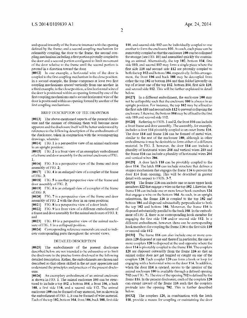
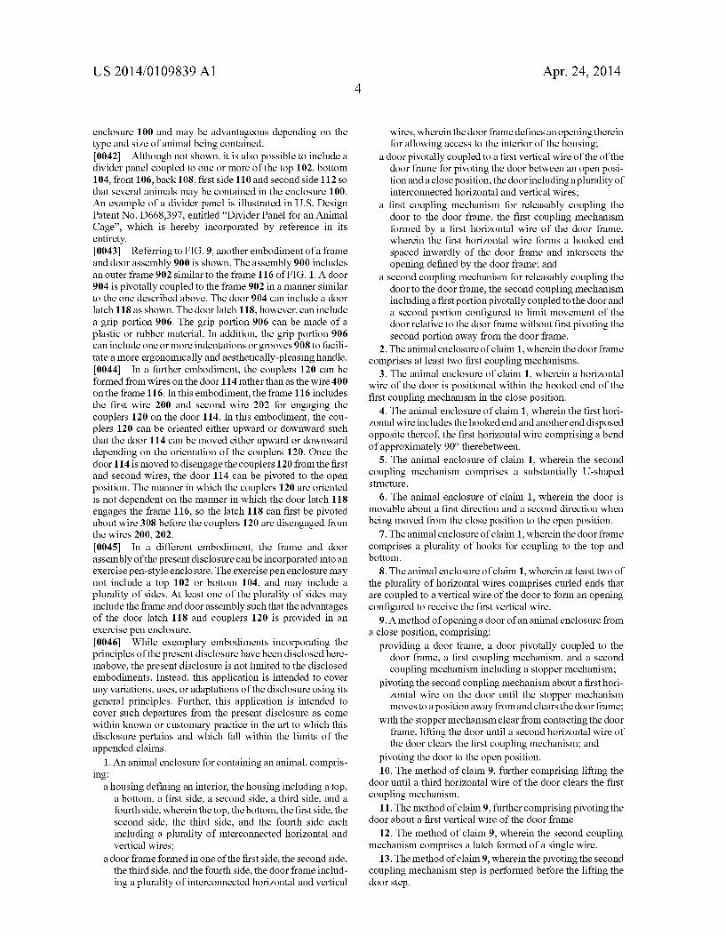
0013 The above-mentioned aspects of the present disclo Sure and the manner of obtaining them will become more apparent and the disclosure itself will be better understood by reference to the following description of the embodiments of the disclosure, taken in conjunction with the accompanying drawings, wherein: 0014 FIG. 1 is a perspective view of an animal enclosure in an upright position; 0015 FIG. 2 is a front view of an exemplary embodiment ofa frame and door assembly for the animal enclosure of FIG. 1: 0016 FIG. 3 is a perspective view of the frame and door assembly of FIG. 2; 0017 FIG. 4 is an enlarged view of a coupler of the frame of FIG.3: 0018 FIG. 5 is another perspective view of the frame and door assembly of FIG. 2; 0019 FIG. 6 is an enlarged view of a coupler of the frame of FIG. 5; 0020 FIG. 7 is a perspective view of the frame and door assembly of FIG. 2 with the door in an open position; 0021 FIG. 8 is a perspective view of a door latch; 0022 FIG. 9 is a front view of a different embodiment of a frame and door assembly for the animal enclosure of FIG.1; and 0023 FIG. 10 is a perspective view of the animal enclo sure of FIG. 1 in a collapsed position. 0024 Corresponding reference numerals are used to indi cate corresponding parts throughout the several views.
DETAILED DESCRIPTION
0025. The embodiments of the present disclosure described below are not intended to be exhaustive or to limit the disclosure to the precise forms disclosed in the following detailed description. Rather, the embodiments are chosen and described so that others skilled in the art may appreciate and understand the principles and practices of the present disclo SUC.
0026. An exemplary embodiment of an animal enclosure is shown in FIG. 1. The animal enclosure 100 can be struc tured to include a top 102, a bottom 104, a front 106, a back 108, a first side 110, and a second side 112. The animal enclosure 100 can be formed of any material, but as shown in the embodiment of FIG. 1, it can be formed of wire material. Each of the top 102, bottom 104, front 106, back 108, first side
Apr. 24, 2014
110, and second side 112 can be individually coupled to one another to form the enclosure 100. As such, each piece can be removably coupled so that the enclosure 100 can be collapsed for storage (see FIG. 10) and assembled quickly for contain ing an animal. Alternatively, the top 102, bottom 104, first side 110, and second 112 may form a single piece where the first side 110 and second side 112 are pivotally coupled to both the top 102 and bottom 104, respectively. In this arrange ment, the front 106 and back 108 may be decoupled from either the top 102 or bottom 104 and then folded inwardly on top of at least one of the top 102, bottom 104, first side 110. and second side 112. This will be further explained in detail below.
0027. In a different embodiment, the enclosure 100 may not be collapsible such that the enclosure 100 is always in an upright position. For instance, the top 102 may be affixed to the first side 110 and second side 112 to prevent collapsing the enclosure. Likewise, the bottom 104 may be affixed to the first side 110 and second side 112. (0028. Referring to FIGS. 1 and 2, the front 106 can include a front frame and door assembly. The assembly, for example, includes a door 114 pivotably coupled to an outer frame 116. The door 114 and frame 116 can be formed of metal wire, similar to the rest of the enclosure 100, although in other embodiments it may be desirable to form either of a different material. In FIG. 2, however, the door 114 can include a plurality of horizontal wires 208 and vertical wires 210 and the frame 116 can include a plurality of horizontal wires 204 and vertical wires 206. 0029. A door latch 118 can be pivotably coupled to the door 114. The latch 118 can include structure that defines a stopper mechanism that engages the frame 116 to prevent the door 114 from opening. This will be described in greater detail with respect to FIGS. 3-7. 0030 The frame 116 can include one or more upper hook members 122 that engage a wire on the top 102. Likewise, the frame 116 can include one or more lower hook members 124 that engage a wire on the bottom 104. As such, in an upright orientation, the frame 116 is coupled to the top 102 and bottom 104 and disposed substantially perpendicular to both the top 102 and bottom 104. Moreover, the frame 116 is disposed substantially parallel to the back 108. In the embodi ment of FIG. 2, there is no corresponding hook member for engaging the first side 110 and/or second side 112. In a different embodiment, however, there can be corresponding hook members for coupling the frame 116 to the first side 110 or second side 112. 0031. The frame 116 can also include one or more cou plers 120 disposed at one end thereof In particular, the one or more couplers 120 is disposed at the end opposite where the door 114 is pivotably coupled to the frame 116. The couplers 120 are disposed outwardly from the frame 116 so that an animal collar does not get tangled or caught on one of the couplers 120. Each coupler 120 can form a hook or loop for engaging with a horizontal wire on the door 114. In addition, when the door 114 is opened, access to the interior of the animal enclosure 100 is available through a defined opening 702 (see FIG. 7). The size of the opening 702 is defined by the frame 116. In the present disclosure, each of the couplers 120 can extend inward of the frame 116 such that the couplers protrude into the opening 702. This is further described below. 0032. The couplers 120, in combination with the latch 118, provide a means for coupling or maintaining the door

US 2014/01 09839 A1
114 is a closed position relative to the frame 116. Moreover, to unlatch or unlock the door 114 relative to the frame 116 can require disengaging the latch 118 from the frame 116 and the door 114 from the couplers 120. This is best illustrated in FIGS. 3-7.
0033 Referring to FIG.3, the door 114 can include a first wire 200 and a second wire 202. The first wire 200 and second wire 202 are substantially parallel to and vertically spaced from one another. Each can be disposed horizontally from one end to an opposite end of the door 114. The first wire 200 can engage an uppermost coupler 120, whereas the second wire 202 can engage a lowermost coupler 120 as shown in FIG. 3. The first wire 200 and second wire 202 are engaged with the couplers 120 when the door 114 is configured in a closed position. 0034. To allow access to the interior of the enclosure 100, the door 114 can be opened. For instance, each of the sub stantially horizontally-disposed wires (e.g., 200, 202) can include curled or hooked ends 300. The curled or hooked ends 300 are disposed at an end opposite the couplers 120 so that the door 114 can pivot with respect to a substantially verti cally-disposed wire 302 of the frame 116. In other words, the wire 302 can pass through each of the curled or hooked ends 300 of the door 114 to permit the door 114 to pivot between an open and closed position with respect to the frame 116. In addition, to maintain the pivotal coupling of the door 114 to the frame 116, the door 114 can include a first vertical wire 310 that is positioned adjacent to the vertical wire 302 of the frame 116. The curled or hooked ends 300 of each horizontal wire can be coupled to the first vertical wire 310. Alterna tively, the curled or hooked ends 300 can be bent such that the end of the wire that forms the curled or hooked ends 300 can be in contact or in near contact with the first vertical wire 310. As such, the curled or hooked ends 300 form an opening through which the vertical wire 302 of the frame 116 can fit and the pivot connection is established. 0035. In the illustrated embodiment, however, simply dis engaging the first wire 200 and second wire 202 from the couplers 120 does not allow the door 114 to be disengaged from the frame 116. To disengage the wires from the couplers, the door 114 is lifted with respect to the frame 116. However, the door latch 118 is structured as a second coupling mecha nism for coupling the door 114 to the frame 116 such that the door latch 118 can prevent the door 114 from being opened. 0036. In FIG. 8, for example, an exemplary embodiment of the door latch 118 is illustrated. Here, the door latch 118 is in the form of a substantially U-shaped wire 800. The U-shaped wire 800 can be a single wire or a plurality of wires coupled to one another. Moreover, the shape of the wire 800 is in the form of a handle so that a user can disengage the door 114 from the frame 116 by using only one hand. At both ends of the wire 800, the latch 118 includes a coupling mechanism 806. In particular, the wire 800 can be bent in such a way as to define a pivot portion 802 and a stopper portion 804. In FIG. 3, for example, the pivot portion 802 of the latch 118 is pivotally coupled to a substantially horizontal wire 308 of the door 114. This allows the latch 118 to pivot freely with respect to the door 114. In addition, the stopperportion 804 defines an opening or slot that can engage a horizontally-disposed wire 304 on the frame 116. Thus, if the latch 118 is in a downward orientation (e.g., in FIGS. 1 and 2), the door 114 cannot be lifted to disengage the first wire 200 and second wire 202 from the couplers 120 due to the stopperportion 804 engaging
Apr. 24, 2014
the wire 304. In this embodiment, interference between the latch 118 and frame 116 is removed before the door is disen gaged from the couplers 120. 0037. In FIG. 3, potential interference between the latch 118 and frame 116 can be removed or avoided by pivoting the latch 118 along a direction indicated by arrow 306. In doing So, the coupling mechanism 806, and in particular the stopper portion 804, is rotated away from the frame 116. In one aspect, the latch 118 can be pivoted nearly 180°. In another aspect, the latch 118 can be pivoted at least 180°. As the latch 118 is pivoted nearly 180°, it can be raised to then disengage the first wire 200 and second wire 202 from the couplers 120. This is best shown in FIGS. 4-6.
0038 Referring to FIG. 4, for instance, the coupler 120 can form a single wire 400 of the frame. One end 402 of the wire 400 can be affixed to the frame 116. For instance, the end 402 can be welded or adhered to the frame 116. A portion of the wire 400 spaced from the end 402 can include an approxi mately 90° bend 600 such that the wire 400 protrudes toward the door 114 (see FIG. 6). The wire 400 can include a curled or hooked end 602 which is opposite from the end 402 of the wire 400. The curled or hooked end 602 forms the coupling function of the coupler 120. 0039. In the illustrated embodiment, the curled or hooked end 602 not only protrudes outward from the frame 116, but it also protrudes inwardly and intersects the access opening 702 of the enclosure 100. In other words, the frame 116 can include a horizontal wire 606 that defines the top edge of the access opening 702 and a vertical wire 604 that defines a right edge of the opening 702 (see FIG. 6). The wire 400, and in particular the curled or hooked end 602, can protrude into the access opening 702 such that it is positioned to the left of the vertical wire 604 and below the horizontal wire 606. The position of the curled or hooked end 602, however, can be spaced from the vertical wire 604 and horizontal wire 606 by a small distance Such that an animal entering or exiting the enclosure 100 is unaffected by the location of the ends 602. 0040. Referring to FIGS. 5 and 6, once the door latch 118
is pivoted about direction 306, the latch 118 or door 114 can be moved along a direction indicated by arrow 500. In this manner, the curled or hooked ends 300 of the horizontally disposed wires of the door 114 can slide or move relative to the vertically-disposed wire 302 of the frame 116. Once the first wire 200 and second wire 202 clear each of the couplers 120, the door 114 can be pivoted or moved along a direction indicated by arrow 700 in FIG.7 to an open position. In doing so, the curled or hooked ends 300 can pivot or rotate about wire 302 of the frame. Once the door 114 is opened, access through an opening 702 defined in the frame 116 is available. 0041 Although only the front 106 of the enclosure is shown in FIG. 1 as including a frame and door assembly, it is possible to include additional frame and door assemblies in the back 108, first side 110, and/or second side 112. For example, the enclosure 100 may include a frame and door assembly in the front 106 and first side 110. The size of the door 114 can be the same regardless of whether it is formed in the front 106, back 108, first side 110 or second side 112. Alternatively, the size of the door 114 can be proportional to the side it is formed in. For instance, if the enclosure is shaped as a rectangle, the enclosure may include both a smaller and larger sized doors. In a different embodiment, it is also pos sible to include a frame and door assembly in the top 102 of the enclosure 100. This allows access through the top of the
US 2014/01 09839 A1
enclosure 100 and may be advantageous depending on the type and size of animal being contained. 0042. Although not shown, it is also possible to include a divider panel coupled to one or more of the top 102, bottom 104, front 106, back 108, first side 110 and second side 112 so that several animals may be contained in the enclosure 100. An example of a divider panel is illustrated in U.S. Design Patent No. D668.397, entitled “Divider Panel for an Animal Cage', which is hereby incorporated by reference in its entirety. 0043 Referring to FIG.9, another embodiment of a frame and door assembly 900 is shown. The assembly 900 includes an outer frame 902 similar to the frame 116 of FIG.1. A door 904 is pivotally coupled to the frame 902 in a manner similar to the one described above. The door 904 can include a door latch 118 as shown. The door latch 118, however, can include a grip portion 906. The grip portion 906 can be made of a plastic or rubber material. In addition, the grip portion 906 can include one or more indentations or grooves 908 to facili tate a more ergonomically and aesthetically-pleasing handle. 0044. In a further embodiment, the couplers 120 can be formed from wires on the door 114 rather than as the wire 400 on the frame 116. In this embodiment, the frame 116 includes the first wire 200 and second wire 202 for engaging the couplers 120 on the door 114. In this embodiment, the cou plers 120 can be oriented either upward or downward such that the door 114 can be moved either upward or downward depending on the orientation of the couplers 120. Once the door 114 is moved to disengage the couplers 120 from the first and second wires, the door 114 can be pivoted to the open position. The manner in which the couplers 120 are oriented is not dependent on the manner in which the door latch 118 engages the frame 116, so the latch 118 can first be pivoted about wire 308 before the couplers 120 are disengaged from the wires 200, 202. 0045. In a different embodiment, the frame and door assembly of the present disclosure can be incorporated into an exercise pen-style enclosure. The exercise pen enclosure may not include a top 102 or bottom 104, and may include a plurality of sides. At least one of the plurality of sides may include the frame and door assembly such that the advantages of the door latch 118 and couplers 120 is provided in an exercise pen enclosure. 0046 While exemplary embodiments incorporating the principles of the present disclosure have been disclosed here inabove, the present disclosure is not limited to the disclosed embodiments. Instead, this application is intended to cover any variations, uses, or adaptations of the disclosure using its general principles. Further, this application is intended to cover Such departures from the present disclosure as come within known or customary practice in the art to which this disclosure pertains and which fall within the limits of the appended claims.
1. An animal enclosure for containing an animal, compris ing:
a housing defining an interior, the housing including a top, a bottom, a first side, a second side, a third side, and a fourth side, wherein the top, the bottom, the first side, the second side, the third side, and the fourth side each including a plurality of interconnected horizontal and vertical wires;
a doorframe formed in one of the first side, the second side, the third side, and the fourth side, the doorframe includ ing a plurality of interconnected horizontal and vertical
Apr. 24, 2014
wires, wherein the doorframe defines an opening therein for allowing access to the interior of the housing:
a door pivotally coupled to a first vertical wire of the of the door frame for pivoting the door between an open posi tion and a close position, the door including a plurality of interconnected horizontal and vertical wires;
a first coupling mechanism for releasably coupling the door to the door frame, the first coupling mechanism formed by a first horizontal wire of the door frame, wherein the first horizontal wire forms a hooked end spaced inwardly of the door frame and intersects the opening defined by the door frame; and
a second coupling mechanism for releasably coupling the door to the door frame, the second coupling mechanism including a first portion pivotally coupled to the door and a second portion configured to limit movement of the door relative to the door frame without first pivoting the second portion away from the door frame.
2. The animal enclosure of claim 1, wherein the doorframe comprises at least two first coupling mechanisms.
3. The animal enclosure of claim 1, wherein a horizontal wire of the door is positioned within the hooked end of the first coupling mechanism in the close position.
4. The animal enclosure of claim 1, wherein the first hori Zontal wire includes the hooked end and another end disposed opposite thereof, the first horizontal wire comprising a bend of approximately 90° therebetween.
5. The animal enclosure of claim 1, wherein the second coupling mechanism comprises a substantially U-shaped Structure.
6. The animal enclosure of claim 1, wherein the door is movable about a first direction and a second direction when being moved from the close position to the open position.
7. The animal enclosure of claim 1, wherein the doorframe comprises a plurality of hooks for coupling to the top and bottom.
8. The animal enclosure of claim 1, wherein at least two of the plurality of horizontal wires comprises curled ends that are coupled to a vertical wire of the door to form an opening configured to receive the first vertical wire.
9. A method of opening a door of an animal enclosure from a close position, comprising:
providing a door frame, a door pivotally coupled to the door frame, a first coupling mechanism, and a second coupling mechanism including a stopper mechanism;
pivoting the second coupling mechanism about a first hori Zontal wire on the door until the stopper mechanism moves to a positionaway from and clears the doorframe;
with the stopper mechanism clear from contacting the door frame, lifting the door until a second horizontal wire of the door clears the first coupling mechanism; and
pivoting the door to the open position. 10. The method of claim 9, further comprising lifting the
door until a third horizontal wire of the door clears the first coupling mechanism.
11. The method of claim 9, further comprising pivoting the door about a first vertical wire of the door frame.
12. The method of claim 9, wherein the second coupling mechanism comprises a latch formed of a single wire.
13. The method of claim 9, wherein the pivoting the second coupling mechanism step is performed before the lifting the door step.
US 2014/01 09839 A1
14. The method of claim 9, further comprising substan tially preventing any lifting movement of the door until the second coupling mechanism is pivoted.
15. The method of claim 14, further comprising substan tially preventing any lifting movement of the door until the stopper mechanism clears the door frame.
16. The method of claim 9, further comprising substan tially preventing the pivoting the door step until after the pivoting the second coupling mechanism step and the lifting the door step.
17. A door frame assembly of an animal enclosure, com prising:
a frame including a plurality of interconnected horizontal and Vertical wires that define an opening in the frame for allowing access therethrough;
a door pivotally coupled to a first vertical wire of the of the frame for pivoting the door between an open position and a close position, the door including a plurality of interconnected horizontal and vertical wires;
a first coupling mechanism for releasably coupling the door to the frame, the first coupling mechanism formed by a first horizontal wire of the frame, wherein the first
Apr. 24, 2014
horizontal wire forms a hooked end protruding outward toward the door and spaced inwardly of the frame to intersect with the opening defined by the frame; and
a second coupling mechanism for releasably coupling the door to the frame, the second coupling mechanism including a first portion pivotally coupled to the door and a second portion configured to limit movement of the door relative to the frame until the second portion is pivoted in a direction toward the door.
18. The door frame assembly of claim 17, wherein a hori Zontal wire of the door is coupled to the first coupling mecha nism in the close position.
19. The door frame assembly of claim 17, wherein the frame comprises at least two first coupling mechanisms spaced vertically from one another.
20. The door frame assembly of claim 19, wherein, in the close position, a first horizontal wire of the door is positioned within an opening formed by one of the first coupling mecha nisms and a second horizontal wire of the door is positioned within an opening formed by another of the first coupling mechanisms.