19 9780789759818 app c
31
APPENDIX C Memory Tables Chapter 1 Table 1-3 Characteristics, Benefits, and Drawbacks of a Star Topology Characteristics Benefits Drawbacks Devices have independent connections back to a central device (for example, a hub or a switch). More cable is required for a star topology, as opposed to bus or ring topologies because each device requires its own cable to connect back to the central device. Star topologies are commonly used with Ethernet technologies (described in Chapter 4). Installation can take longer for a star topology, as opposed to a bus or ring topology, because more cable runs that must be installed. Table 1-4 Characteristics, Benefits, and Drawbacks of a Hub-and-Spoke WAN Topology Characteristics Benefits Drawbacks Each remote site (that is, a spoke) connects back to a main site (that is, the hub) via a WAN link. Suboptimal routes must be used between remote sites because all intersite communication must travel via the main site. Communication between two remote sites travels through the hub site. Because all remote sites converge on the main site, this hub site potentially becomes a single point of failure. — — Because each remote site is reachable by only a single WAN link, the hub- and-spoke topology lacks redundancy.
Transcript of 19 9780789759818 app c

Appendix C
Memory Tables
Chapter 1Table 1-3 Characteristics, Benefits, and drawbacks of a Star Topology
Characteristics Benefits Drawbacks
Devices have independent connections back to a central device (for example, a hub or a switch).
More cable is required for a star topology, as opposed to bus or ring topologies because each device requires its own cable to connect back to the central device.
Star topologies are commonly used with Ethernet technologies (described in Chapter 4).
Installation can take longer for a star topology, as opposed to a bus or ring topology, because more cable runs that must be installed.
Table 1-4 Characteristics, Benefits, and drawbacks of a Hub-and-Spoke WAn Topology
Characteristics Benefits Drawbacks
Each remote site (that is, a spoke) connects back to a main site (that is, the hub) via a WAN link.
Suboptimal routes must be used between remote sites because all intersite communication must travel via the main site.
Communication between two remote sites travels through the hub site.
Because all remote sites converge on the main site, this hub site potentially becomes a single point of failure.
— — Because each remote site is reachable by only a single WAN link, the hub-and-spoke topology lacks redundancy.

4 CompTiA network+ n10-007 Cert Guide
Table 1-5 Characteristics, Benefits, and drawbacks of a Full-Mesh WAn Topology
Characteristics Benefits Drawbacks
Every site has a direct WAN connection to every other site.
A full-mesh network can be difficult and expensive to scale, because the addition of one new site requires a new WAN link between the new site and every other existing site.
The number of required WAN connections can be calculated with the formula w = n * (n – 1) / 2, where w = the number of WAN links and n = the number of sites. For example, a network with 10 sites would require 45 WAN connections to form a fully meshed network: 45 = 10 * (10 – 1) / 2.
— —
Table 1-6 Characteristics, Benefits, and drawbacks of a partial-Mesh Topology
Characteristics Benefits Drawbacks
Selected sites (that is, sites with frequent intersite communication) are interconnected via direct links, whereas sites that have less-frequent communication can communicate via another site.
A partial-mesh topology is less fault tolerant than a full-mesh topology.
Appendix C: Memory Tables 5
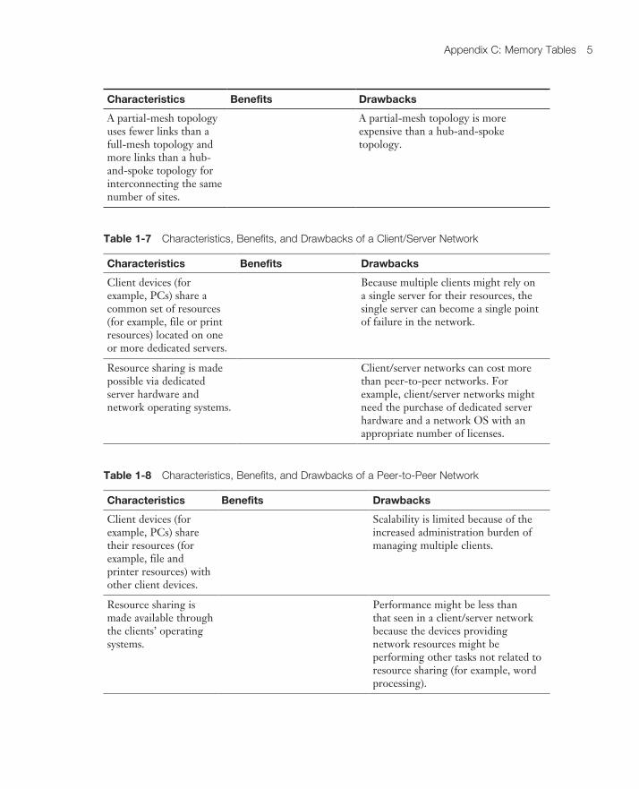
Characteristics Benefits Drawbacks
A partial-mesh topology uses fewer links than a full-mesh topology and more links than a hub-and-spoke topology for interconnecting the same number of sites.
A partial-mesh topology is more expensive than a hub-and-spoke topology.
Table 1-7 Characteristics, Benefits, and drawbacks of a Client/Server network
Characteristics Benefits Drawbacks
Client devices (for example, PCs) share a common set of resources (for example, file or print resources) located on one or more dedicated servers.
Because multiple clients might rely on a single server for their resources, the single server can become a single point of failure in the network.
Resource sharing is made possible via dedicated server hardware and network operating systems.
Client/server networks can cost more than peer-to-peer networks. For example, client/server networks might need the purchase of dedicated server hardware and a network OS with an appropriate number of licenses.
Table 1-8 Characteristics, Benefits, and drawbacks of a peer-to-peer network
Characteristics Benefits Drawbacks
Client devices (for example, PCs) share their resources (for example, file and printer resources) with other client devices.
Scalability is limited because of the increased administration burden of managing multiple clients.
Resource sharing is made available through the clients’ operating systems.
Performance might be less than that seen in a client/server network because the devices providing network resources might be performing other tasks not related to resource sharing (for example, word processing).

6 CompTiA network+ n10-007 Cert Guide
Chapter 2Table 2-1 Application Layer protocols/Applications
Protocol Description TCP Port UDP Port
DHCP Dynamic Host Configuration Protocol: Dynamically assigns IP address information (for example, IP address, subnet mask, DNS server’s IP address, and default gateway’s IP address) to a network device
DNS Domain Name System: Resolves domain names to corresponding IP addresses
FTP File Transfer Protocol: Transfers files with a remote host (typically requires authentication of user credentials)
H.323 A signaling protocol that provides multimedia communications over a network
HTTP Hypertext Transfer Protocol: Retrieves content from a web server
HTTPS Hypertext Transfer Protocol Secure: Used to securely retrieve content from a web server
IMAP Internet Message Access Protocol: Retrieves email from an email server
IMAP4 Internet Message Access Protocol Version 4: Retrieves email from an email server
LDAP Lightweight Directory Access Protocol: Provides directory services (for example, a user directory that includes username, password, email, and phone number information) to network clients
LDAPS Lightweight Directory Access Protocol over SSH: A secured version of LDAP
MGCP Media Gateway Control Protocol: Used as a call control and communication protocol for Voice over IP networks
NetBIOS Network Basic Input/Output System: Provides network communication services for LANs that use NetBIOS
NNTP Network News Transport Protocol: Supports the posting and reading of articles on Usenet news servers
NTP Network Time Protocol: Used by a network device to synchronize its clock with a time server (NTP server)
POP3 Post Office Protocol Version 3: Retrieves email from an email server
Appendix C: Memory Tables 7
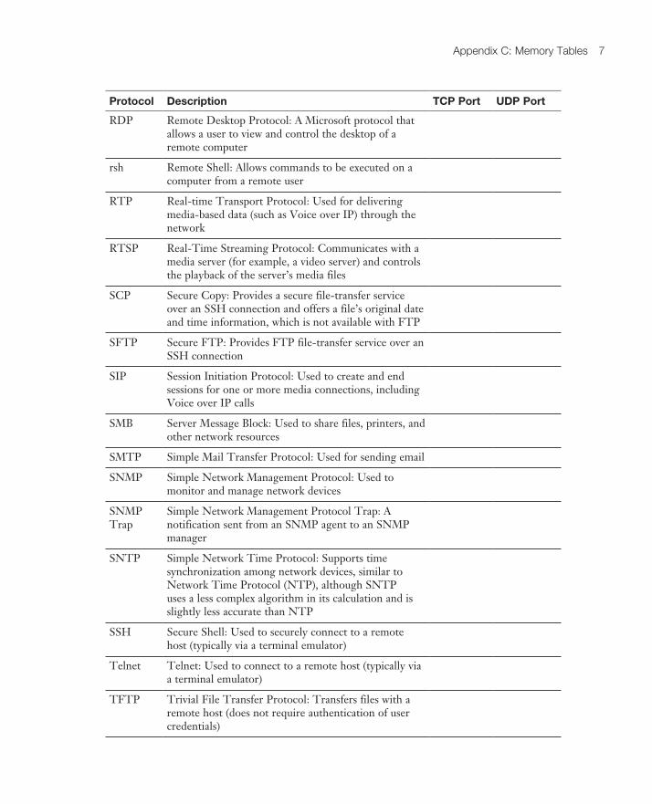
Protocol Description TCP Port UDP Port
RDP Remote Desktop Protocol: A Microsoft protocol that allows a user to view and control the desktop of a remote computer
rsh Remote Shell: Allows commands to be executed on a computer from a remote user
RTP Real-time Transport Protocol: Used for delivering media-based data (such as Voice over IP) through the network
RTSP Real-Time Streaming Protocol: Communicates with a media server (for example, a video server) and controls the playback of the server’s media files
SCP Secure Copy: Provides a secure file-transfer service over an SSH connection and offers a file’s original date and time information, which is not available with FTP
SFTP Secure FTP: Provides FTP file-transfer service over an SSH connection
SIP Session Initiation Protocol: Used to create and end sessions for one or more media connections, including Voice over IP calls
SMB Server Message Block: Used to share files, printers, and other network resources
SMTP Simple Mail Transfer Protocol: Used for sending email
SNMP Simple Network Management Protocol: Used to monitor and manage network devices
SNMP Trap
Simple Network Management Protocol Trap: A notification sent from an SNMP agent to an SNMP manager
SNTP Simple Network Time Protocol: Supports time synchronization among network devices, similar to Network Time Protocol (NTP), although SNTP uses a less complex algorithm in its calculation and is slightly less accurate than NTP
SSH Secure Shell: Used to securely connect to a remote host (typically via a terminal emulator)
Telnet Telnet: Used to connect to a remote host (typically via a terminal emulator)
TFTP Trivial File Transfer Protocol: Transfers files with a remote host (does not require authentication of user credentials)
8 CompTiA network+ n10-007 Cert Guide
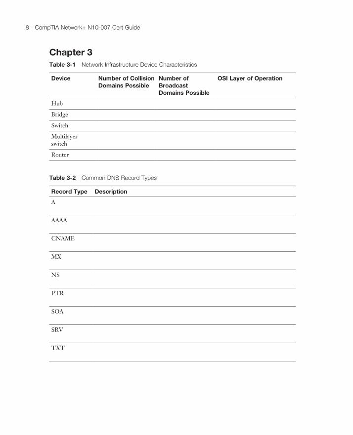
Chapter 3Table 3-1 network infrastructure device Characteristics
Device Number of Collision Domains Possible
Number of Broadcast Domains Possible
OSI Layer of Operation
Hub
Bridge
Switch
Multilayer switch
Router
Table 3-2 Common dnS Record Types
Record Type Description
A
AAAA
CNAME
MX
NS
PTR
SOA
SRV
TXT

Appendix C: Memory Tables 9
Table 3-3 Voip network elements
Protocol/Device Description
IP phone
Call agent
Gateway
PBX
Analog phone
SIP
RTP
Chapter 4Table 4-1 ethernet Bandwidth Capacities
Ethernet Type Bandwidth Capacity
Standard Ethernet
Fast Ethernet
Gigabit Ethernet

10 CompTiA network+ n10-007 Cert Guide
Ethernet Type Bandwidth Capacity
10-Gigabit Ethernet
100-Gigabit Ethernet
Table 4-2 Types of ethernet
Ethernet Standard Media Type Bandwidth Capacity
Distance Limitation
10BASE5 500 m
10BASE2 185 m
10BASE-T 100 m
100BASE-TX 100 m
100BASE-FX 2 km
1000BASE-T 100 m
1000BASE-TX 100 m
1000BASE-LX 5 km
1000BASE-LH 10 km
1000BASE-ZX 70 km
10GBASE-SR 26 m–400 m
10GBASE-LR 10 km–25 km
10GBASE-ER 40 km
10GBASE-SW 300 m
10GBASE-LW 10 km
10GBASE-EW 40 km
10GBASE-T 100 m
100GBASE-SR10 125 m
100GBASE-LR4 10 km
100GBASE-ER4 40 km

Appendix C: Memory Tables 11
Table 4-3 STp port Types
Port Type Description
Root port
Designated port
Nondesignated port
Chapter 5Table 5-1 Binary Conversion Table
Table 5-19 ip Address Classes
Address Class Value in First Octet Classful Mask (Dotted Decimal)
Classful Mask (Prefix Notation)
Class A /8
Class B /16
Class C /24
Class D — —Class E — —
Table 5-20 private ip networks
Address Class Address Range Default Subnet Mask
Class A 255.0.0.0
Class B 255.255.0.0
Class B 255.255.0.0
Class C 255.255.255.0
12 CompTiA network+ n10-007 Cert Guide
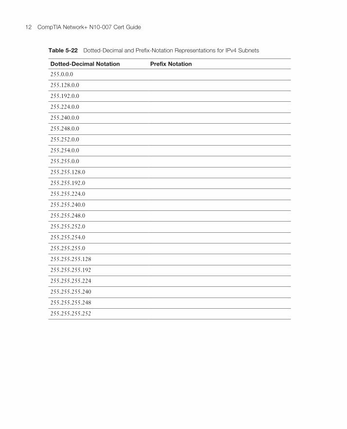
Table 5-22 dotted-decimal and prefix-notation Representations for ipv4 Subnets
Dotted-Decimal Notation Prefix Notation
255.0.0.0
255.128.0.0
255.192.0.0
255.224.0.0
255.240.0.0
255.248.0.0
255.252.0.0
255.254.0.0
255.255.0.0
255.255.128.0
255.255.192.0
255.255.224.0
255.255.240.0
255.255.248.0
255.255.252.0
255.255.254.0
255.255.255.0
255.255.255.128
255.255.255.192
255.255.255.224
255.255.255.240
255.255.255.248
255.255.255.252

Appendix C: Memory Tables 13
Table 5-24 number of Subnets Created by a Specified number of Borrowed Bits
Borrowed Bits Number of Subnets Created (2s, Where s Is the Number of Borrowed Bits)
0
1
2
3
4
5
6
7
8
9
10
11
12
Table 5-25 number of Supported Hosts Given a Specified number of Host Bits
Host Bits Number of Supported Hosts (2h–2, Where h Is the Number of Host Bits)
2
3
4
5
6
7
8
9
10
11
12

14 CompTiA network+ n10-007 Cert Guide
Chapter 6Table 6-1 Administrative distance
Routing Information Source Administrative Distance
Directly connected network
Statically configured network
EIGRP
OSPF
RIP
External EIGRP
Unknown of unbelievable
Table 6-2 names of nAT ip Addresses
NAT IP Address Definition
Inside local
Inside global
Outside local
Outside global
Chapter 7Table 7-1 Typical WAn data Rates
WAN Technology Typical Available Bandwidth
Frame Relay
T1
T3
E1
E3
ATM
SONET
Appendix C: Memory Tables 15
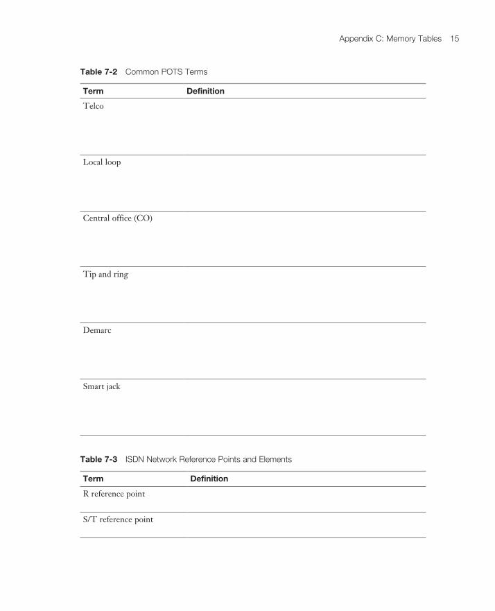
Table 7-2 Common pOTS Terms
Term Definition
Telco
Local loop
Central office (CO)
Tip and ring
Demarc
Smart jack
Table 7-3 iSdn network Reference points and elements
Term Definition
R reference point
S/T reference point
16 CompTiA network+ n10-007 Cert Guide
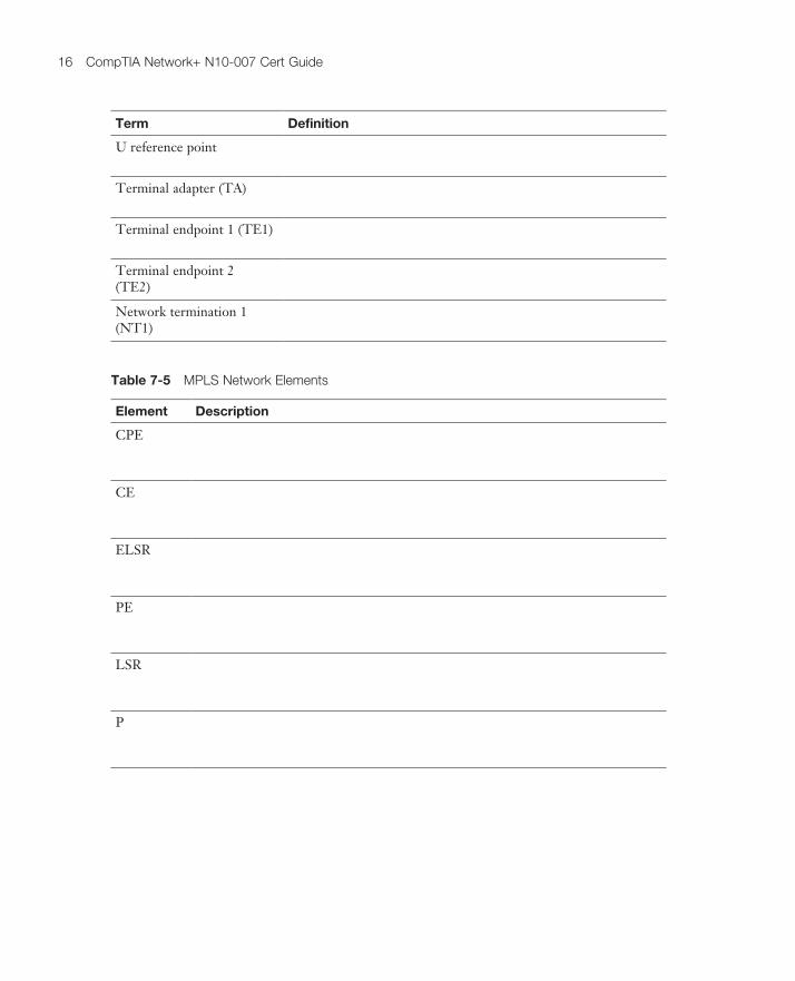
Term Definition
U reference point
Terminal adapter (TA)
Terminal endpoint 1 (TE1)
Terminal endpoint 2 (TE2)
Network termination 1 (NT1)
Table 7-5 MpLS network elements
Element Description
CPE
CE
ELSR
PE
LSR
P

Appendix C: Memory Tables 17
Chapter 8Table 8-3 Characteristics of 802.11 Standards
Standard Band Max. Bandwidth Transmission Method
Max. Range
802.11 DSSS or FHSS
802.11a OFDM
802.11b DSSS
802.11g OFDM or DSSS
802.11n OFDM
802.11ac OFDM
Chapter 9Table 9-1 Three Categories of Quality issues
Issue Description
Delay
Jitter
Drops

18 CompTiA network+ n10-007 Cert Guide
Table 9-2 Three Categories of QoS Mechanisms
Issue Description
Best effort
Integrated Services (IntServ)
Differentiated services (DiffServ)
Chapter 10Table 10-2 parameters for the Windows ipconfig Command
Parameter Purpose
/all
/release and /release6
/renew and /renew6
Table 10-5 parameters for the Windows ping Command
Parameter Purpose
-t
-n count

Appendix C: Memory Tables 19
Parameter Purpose
-f
-i TTL
-S srcaddr
target_name
Table 10-6 parameters for the Windows route Command
Parameter Purpose
-f
-p
command
destination
mask netmask
gateway
metric metric
if interface

20 CompTiA network+ n10-007 Cert Guide
Chapter 11Table 11-1 Components of an SnMpv1 and SnMpv2c network-Management Solution
Component Description
SNMP manager
SNMP agent
Management Information Base (MIB)
Table 11-2 Security Models and Security Levels Supported by Cisco iOS
Security Model Security Level Authentication Strategy Encryption Type
SNMPv1 Community string None
SNMPv2c Community string None
SNMPv3 Username None
SNMPv3 MD5 or SHA None
SNMPv3 MD5 or SHA CBC-DES (DES-56)
Table 11-3 Syslog Severity Levels
Level Name Description
0 The most severe error conditions, which render the system unusable
1 Conditions requiring immediate attention
2 A less-severe condition, as compared to alerts, that should be addressed to prevent an interruption of service
3 Notifications about error conditions within the system that do not render the system unusable
4 Notifications that specific operations failed to complete successfully
5 Non-error notifications that alert an administrator about state changes within a system

Appendix C: Memory Tables 21
Level Name Description
6 Detailed information about the normal operation of a system
7 Highly detailed information (for example, information about individual packets) that is typically used for troubleshooting purposes
Chapter 12Table 12-1 Confidentiality Attack Tactics
Tactic Description
Packet capture
Ping sweep and port scan
Dumpster diving
Electromagnetic interference (EMI) interception

22 CompTiA network+ n10-007 Cert Guide
Tactic Description
Wiretapping
Man-in-the-middle (MitM)
Social engineering
Sending information over overt channels
Sending information over covert channels
Malware

Appendix C: Memory Tables 23
Tactic Description
FTP bounce
Phishing
Table 12-2 Remote-Access Security Methods
Method Description
RAS
RDP
PPPoE
PPP

24 CompTiA network+ n10-007 Cert Guide
Method Description
ICA
SSH
Kerberos
AAA
RADIUS
TACACS+
NAC
IEEE 802.1X

Appendix C: Memory Tables 25
Method Description
CHAP
MS-CHAP
EAP
Two-factor authentication
Multifactor authentication
Single sign-on
Local authentication
LDAP
Captive portal

26 CompTiA network+ n10-007 Cert Guide
Table 12-3 iKev1 Modes
Mode Description
Main mode
Aggressive mode
Quick mode
Table 12-4 examples of Vpn protocols
Protocol Description
SSL
L2TP

Appendix C: Memory Tables 27
Protocol Description
L2F
PPTP
TLS
Chapter 14Table 14-1 Steps to diagnose a problem
Step Description
Because a typical problem report lacks sufficient information to give a troubleshooter insight into a problem’s underlying cause, the troubleshooter should collect additional information, perhaps using network maintenance tools or interviewing impacted users.
Testing to see if you can duplicate the problem is often a key step in problem diagnosis.
Although it can be difficult to gather information from your end users, this is often critical in correctly pinpointing the exact problem. Oftentimes, finding out user actions prior to the problem is critical.
What are the actual symptoms the problem has created.
Perhaps your end users will provide valuable clues if they accurately indicate what changes they might have made to systems.
Unfortunately, you might discover there are multiple issues. Be sure to approach each one individually.

28 CompTiA network+ n10-007 Cert Guide
Table 14-2 Common Layer 1 Troubleshooting issues
Issue Description
Bad cables or connectors
Bad port
Opens and shorts
Splitting pairs in a cable
dB loss
Transposed Tx/Rx leads
Cable placement

Appendix C: Memory Tables 29
Issue Description
Distance limitations exceeded
Crosstalk
Speed/duplex mismatch
Table 14-3 Common Layer 2 Troubleshooting issues
Issue Description
Power failure
Bad module
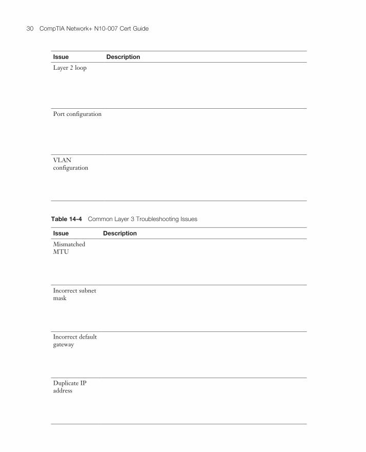
30 CompTiA network+ n10-007 Cert Guide
Issue Description
Layer 2 loop
Port configuration
VLAN configuration
Table 14-4 Common Layer 3 Troubleshooting issues
Issue Description
Mismatched MTU
Incorrect subnet mask
Incorrect default gateway
Duplicate IP address
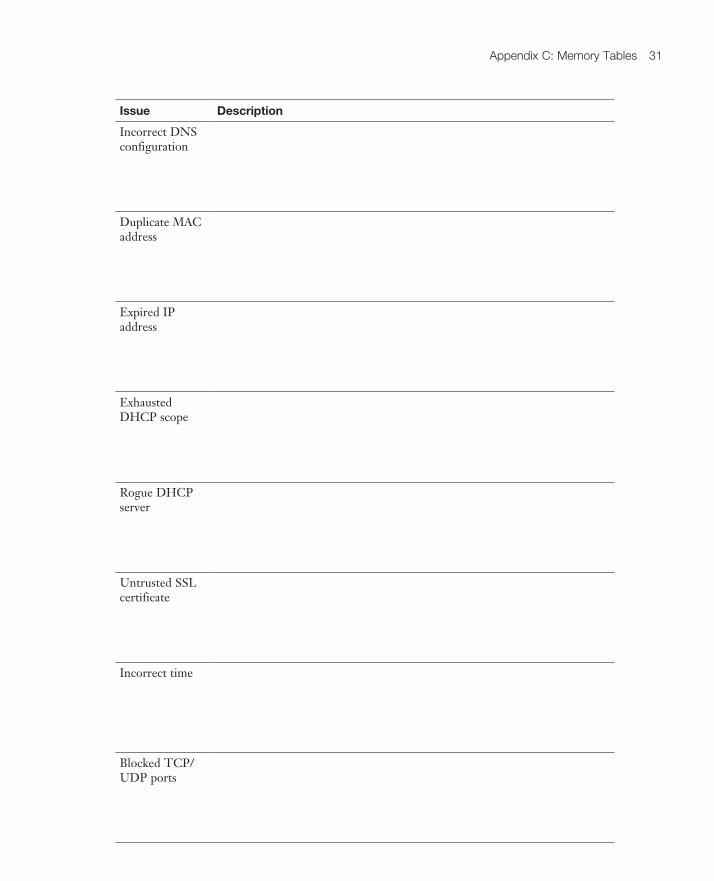
Appendix C: Memory Tables 31
Issue Description
Incorrect DNS configuration
Duplicate MAC address
Expired IP address
Exhausted DHCP scope
Rogue DHCP server
Untrusted SSL certificate
Incorrect time
Blocked TCP/UDP ports

32 CompTiA network+ n10-007 Cert Guide
Issue Description
Incorrect host-based firewall settings
Incorrect ACL settings
Unresponsive service
Table 14-5 Common Wireless Troubleshooting issues
Issue Description
RFI
Signal strength
Misconfiguration of wireless parameters

Appendix C: Memory Tables 33
Issue Description
Latency
Multiple paths of propagation
Incorrect AP placement