18OBC DIY - BMW E36 Conversion-Upgrade · 1998.5 BMW E36 18 Button OBC Conversion -Upgrade DIY By...
40
1998.5 BMW E36 18 Button OBC Conversion-Upgrade DIY By Jeremy Reyna ([email protected]) Also includes items from various other sources.
Transcript of 18OBC DIY - BMW E36 Conversion-Upgrade · 1998.5 BMW E36 18 Button OBC Conversion -Upgrade DIY By...
1998.5 BMW E36 18 Button OBC Conversion-Upgrade DIY
By Jeremy Reyna ([email protected])
Also includes items from various other sources.

1998.5 BMW E36 M3 ON‐ BOARD COM PUTER CONVERSI ON
September 2004 1 Jeremy Reyna ([email protected])
1) OBJECTIVE a) To replace the 11‐Button OBC that came with my 1998.5 E36 M3 with an 18‐Button
OBC. This requires creating and routing a second wiring harness needed for the 18‐Button OBC.
b) Disclaimer: This DIY worked fine for my vehicle. There may be slight differences between vehicles, but the basics should be similar.
2) REFERENCE a) My car information
i) June 1998 build, AW/BLK ii) Factory Options
(1) Power Sunroof (2) Heated Seats (3) LTW Forged Wheels
iii) BMW Installed Options (1) Class III OEM Alarm (2) Euro Headlights, turn signals, rear lights
b) Pelican Guest Technical Article – “BMW On‐Board Computer Retrofit/Conversion” i) http://www.pelicanparts.com/bmw/techarticles/E36‐OBD_Convert/E36‐
OBD_Convert.htm ii) Corrections: My install was different from this DIY…differences follow…
(1) X1071‐Pin4 (brown/red) routes to the OBC Turn Signal Stalk. The Pelican DIY says to route and tap into the brown/red wire of the OBC Turn Stalk Harness. This was not the case in my install, as the brown/red wire did not cycle the 18OBC. There is a brown/red wire in the OBC Turn Stalk Harness, but it goes to the connector for the slip ring/steering wheel. The OBC Turn signal has one more wire in the harness that the regular turn signal does not have….it is a YELLOW/RED wire. This is the wire I used to make the 18OBC cycle through the functions. As a note, the correct wire can be found by following the two black wires at the base of the stalk to two solder points. One of those wires will make the obc cycle and the other is probably ground (brown). Lars told me that the OBC will cycle when the Pin4 wire gets grounded.
(2) X1071‐Pin6 (black/white) routes to the X16 instrument cluster connector. The Pelican DIY says to route this wire to the X16 connector and plug it into the empty X16‐Pin21. In my case, Pin21 was not empty. As a result, I just tapped into the existing black/white wire.
(3) X1071‐Pin9 (white/gray) routes to the X17 instrument cluster connector. The Pelican DIY says to route this Pin9 wire to the X17 harness and tap into the white/gray wire. In my case, the white/gray wire was missing and the corresponding slot in the X17 connector was empty. As a result, I just spliced a pin to the X1071‐Pin9 wire and plugged it into empty the X17‐Pin10 location.
Tony Scarola

1998.5 BMW E36 M3 ON‐BOARD COMPUTER CONVERSION
September 2004 2 Jeremy Reyna ([email protected])
c) Bimmerforums.com Search i) http://forums.bimmerforums.com/forum/showthread.php?s=&threadid=87693&high
light=obc%2A+conversion d) Bimmer.Roadfly.org Search
3) DIY OVERVIEW (get an idea of what you have to do) a) Recommendations/Notes
i) Use a Bentley Manual. I found it invaluable. ii) I don’t recommend doing the install all in one day. The contortionism required to
get to some of these harnesses tires you out and can be a little frustrating at times. The heat associated with working under the dash does not help. Be patient and take it one step at a time. My lack of patience in some cases resulted in scratched trim, etc. I had a second car which made the install much easier and allowed me to work on this project at my leisure.
iii) I did not have to cut any of the cars existing wiring harnesses. I only tapped in to existing wires. This method makes this retrofit completely reversible…however time consuming to undo.
iv) This DIY is written for the scenario experienced with my particular car. It is very possible that things may not go exactly as outlined in this and other DIYs.
v) It helps if you can look at your X16, X17 and X1659 connectors/pins in your own car before building the X1071 wiring harness. This way you can verify that the wire you are to tap into exists and also verify the proper pin slots are empty. This will ensure you are building the X1071 wiring harness that fits your car.
vi) Read the whole DIY before beginning. It’s probably too long, but better too much information than not enough.
b) Assembly Time ~ 7‐10 hours i) I’m a really slow worker. I wrote down times it took me to get to certain steps and I
approximated the assembly time taking into account all of the disassembly of the interior. In actuality, it took me days over a span of a couple weeks (ordering, shipping, bits after work, etc). Some of my effort was spent figuring out issues that arose. Hopefully this DIY will help you reduce the overall time required to install.
c) Installation Overview i) Acquire 18‐Button OBC, X1071, X16, X17 and X1659 connectors with pigtails and
18awg stranded hookup wire. ii) Extract one pin/wire from the X1659 connector OR buy the appropriate BMW pin. iii) Extract one pin/wire from either the X16 or X17 connector, depending on your
vehicle OR buy the appropriate BMW pin. iv) Use provided schematic (18OBC DIY 2of2 – BMW E36 X1071 wiring harness
schematic) to make the new wiring harness using acquired X1071 connector (with pigtail), stranded hookup wire and 2 extracted pins/wires.
v) Disconnect Negative Battery Cable

1998.5 BMW E36 M3 ON‐BOARD COMPUTER CONVERSION
September 2004 3 Jeremy Reyna ([email protected])
vi) Remove glovebox, existing OBC, steering wheel, airbag and instrument cluster. vii) Install OBC Turn Signal Stalk viii) Route new wiring harness individual wires to the appropriate location ix) Tap six wires into existing oem harnesses x) Plug two pins into appropriate connectors depending on your car’s wiring. xi) Plug in X1071 connector and existing X1070 connector into 18 Button OBC. xii) Reconnect Battery and Test. xiii) Make final tie downs and organize routed wires.
4) MATERIALS/TOOLS/COMPONENT PURCHASES a) Tools/Materials
i) T30 Torx – Steering Wheel Airbag ii) 10mm Socket – Glove Box Bolt under light cover, Knee Bolster iii) 13mm Socket – Negative Battery Cable iv) 16mm Socket – Steering Wheel Bolt v) Torque Wrench – Steering Wheel Bolt, 63 N‐m (Bentley) vi) Dremel Tool with cutting disk. vii) 3/8 Socket Drive or equivalent viii) Phillips/Flathead Screwdriver ix) Drop light x) Pliers xi) Soldering Iron/Solder xii) Tie Wraps xiii) Wire cutters xiv) Friction Tape (Figure 9) xv) Torque Wrench xvi) Scissors xvii) 18‐22awg red splice clips or equivalent (Figure 15) xviii) Heat Shrink
b) Purchases/Acquisitions i) 18 Button OBC – I bought one from Bavarian Auto Exchange for ~ $145. They are
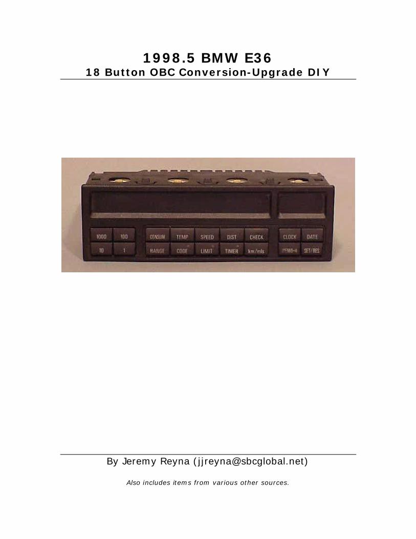
readily available everywhere (ebay, bf classifieds, etc). Be sure to use the same color bulbs (or new ones) as that came out of your original OBC (Figure 1a, 1b). While bulb glass is not colored, the backing is; tan or black. My 98.5 came with the black ones. I don’t really think it’s that important, but you want to match the output of what’s already in your car.
1998.5 BMW E36 M3 ON‐BOARD COMPUTER CONVERSION
September 2004 4 Jeremy Reyna ([email protected])
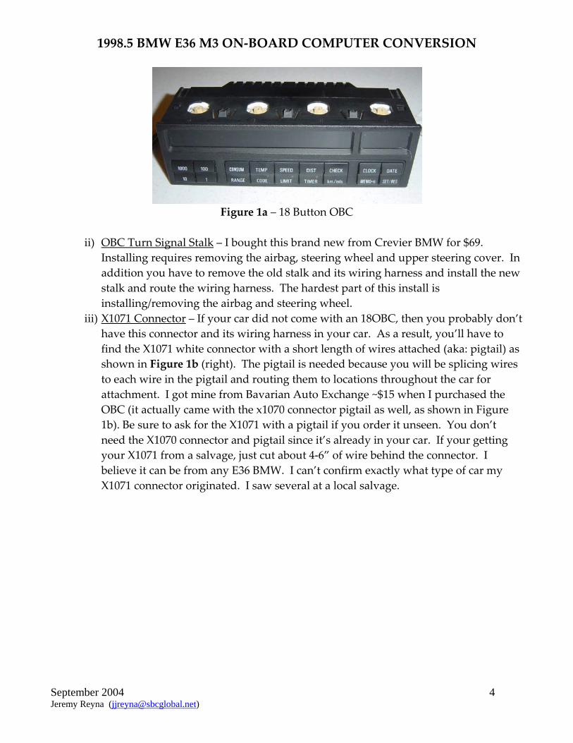
Figure 1a – 18 Button OBC
ii) OBC Turn Signal Stalk – I bought this brand new from Crevier BMW for $69.
Installing requires removing the airbag, steering wheel and upper steering cover. In addition you have to remove the old stalk and its wiring harness and install the new stalk and route the wiring harness. The hardest part of this install is installing/removing the airbag and steering wheel.
iii) X1071 Connector – If your car did not come with an 18OBC, then you probably don’t have this connector and its wiring harness in your car. As a result, you’ll have to find the X1071 white connector with a short length of wires attached (aka: pigtail) as shown in Figure 1b (right). The pigtail is needed because you will be splicing wires to each wire in the pigtail and routing them to locations throughout the car for attachment. I got mine from Bavarian Auto Exchange ~$15 when I purchased the OBC (it actually came with the x1070 connector pigtail as well, as shown in Figure 1b). Be sure to ask for the X1071 with a pigtail if you order it unseen. You don’t need the X1070 connector and pigtail since it’s already in your car. If your getting your X1071 from a salvage, just cut about 4‐6” of wire behind the connector. I believe it can be from any E36 BMW. I can’t confirm exactly what type of car my X1071 connector originated. I saw several at a local salvage.

1998.5 BMW E36 M3 ON‐BOARD COMPUTER CONVERSION
September 2004 5 Jeremy Reyna ([email protected])
Figure 1b – 18 Button OBC shown with X1071 (right) and X1070 connectors w/pigtails.
iv) X16 and/or X17 Connector – These are connectors found behind the instrument
cluster of any E36 BMW. You are acquiring these connectors because you will need to extract a SINGLE pin/wire for use in this DIY (as shown in Figure 4). The pin/wire will be spliced to one of the wires from the X1071 connector and then plugged into an empty slot on one of the instrument cluster connectors on your car. Both connectors contain the same pins and collecting both only serves to ensure you’ll have the proper color wire to match to the X1071 connector pigtail. If that’s not important to you, just buy one and pick any pin to extract. If it is, then buy both. Once you understand the wiring schematic and actually see what kind of wiring you have behind your instrument cluster, you will understand which pin/wire you’ll need. Acquire them with a pigtail. The X16 is white and the X17 is blue (Figure 2). Any E36 will have these connectors. Mine were from a 94‐325is which I located at a local salvage.

1998.5 BMW E36 M3 ON‐BOARD COMPUTER CONVERSION
September 2004 6 Jeremy Reyna ([email protected])
Figure 2 – White X16 (right) and Blue X17 (center) Instrument Cluster Connectors. v) X1659 Connector – As with the X16 and X17 connectors, you are buying this
connector to extract a single pin/wire for use in this DIY (Figure 4). You will need to acquire this connector with a pigtail. The connector in my 98.5 M3 was red, directly behind the glovebox sheetmetal crossmember and under a blue connector of the same size (Figure 3). It is a large connector with wires matching the colors in the Bentley manual (ELE‐150). In my car, Pins 6, 10, 11 and 15 were empty. The empty slot Pin 15 is the one that will be utilized for this DIY. In cars with cruise installed, Pin15 is wired with a Blk/Grn wire. I bought this connector from the same salvage I got the other connectors. In my case, the X1659 I acquired was off a 97‐M3.
Figure 3 – X1659 EWS Connector being disassembled.

1998.5 BMW E36 M3 ON‐BOARD COMPUTER CONVERSION
September 2004 7 Jeremy Reyna ([email protected])
vi) 18 AWG Stranded Hookup Wire – Bought for ~$35. In the following 8 colors:
Orange, Gray, Violet, Red, White, Yellow, Brown and Black. vii) Friction Tape – Bought for ~$2.99 viii) Heat Shrink
5) X1071 WIRING HARNESS a) Get Organized
i) Connector Definitions (1) X1070 – Black connector and wiring harness already in your car used for existing
OBC. (2) X1071 – White connector and wiring harness required for 18 button OBC (3) X16 – White connector behind instrument cluster (4) X17 – Blue connector behind instrument cluster (5) X1659 – EWSII connector behind glove box
ii) Record base‐line pin locations of acquired X1071 Connector for reference (1) On my connector, pins 10 through 12 and pins 14 through 18 were empty.
(a) Pin1 – Black/Purple (b) Pin2 – Purple/Green/Yellow Dots (c) Pin3 – Black/Blue (d) Pin4 – Brown/Red (e) Pin5 – White/Violet (lighter than purple) (f) Pin6 – White/Black (g) Pin7 – White/Yellow (h) Pin8 – Red/Gray/Yellow Dots (i) Pin9 – White/Gray (j) Pin13 – Brown
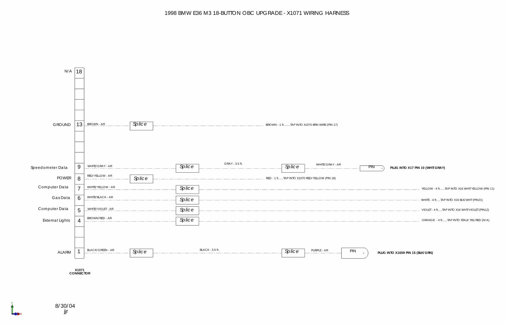
b) Create wiring harness schematic of X1071 connector (Attached) i) Use the acquired X1071 connector and the referenced Pelican Guest Article to create
the schematic of the new wiring harness (See attached PDF file 18OBC DIY 2of2 BMW E36 X1071 wiring harness schematic). If you have the attachment, you can skip the next section summarizing the wiring harness schematic.
ii) The following summarizes the wiring harness schematic and identifies the routing destination, wire color and method of attachment. ‘Cable’ – describes how the individual wires should be built. Example: (2) SpFrom X1071 Pin 4 splice 4.0’ of orange wire. Note: AR = as required. Strikethroughs identify where my experience was different from that of the Pelican Article. (1) X1071‐Pin1 (black/green wire)
(a) Cable: Splice 3.5 ft. of BLACK wire to X1071‐Pin1 pigtail. Splice large pin (Figure 4) from extracted X1659 connector to BLACK wire.
(b) Destination: EWS, Anti‐Theft System – Behind Glove Box

1998.5 BMW E36 M3 ON‐BOARD COMPUTER CONVERSION
September 2004 8 Jeremy Reyna ([email protected])
(c) Action: Plug into empty Pin15 on the X1659 ZKE IV Control Module (2) X1071‐Pin4 (brown/red wire)
(a) Cable: Splice 4 ft. of ORANGE wire to X1071‐Pin4 pigtail (b) Destination: Exterior Lights System ‐ Turn Signal Stalk (c) Action: Tap into the yellow/red wire on the OBC turn signal stalk harness
(3) X1071‐Pin5 (white/violet wire) (a) Cable: Splice 4 ft. of VIOLET wire to X1071‐Pin5 pigtail (b) Destination: Computer Data Line System – Instrument Cluster (c) Action: Tap into white/violet (pin12) wire on the X16 connector harness
(4) X1071‐Pin6 (white/black wire) (a) Cable: Splice 4 ft. of WHITE wire to X1071‐Pin6 pigtail (b) Destination: Engine Controls System (gas gauge) – Instrument Cluster (c) Action: Tap into white/black wire (pin21) on the X16 connector harness
(5) X1071‐Pin7 (white/yellow wire) (a) Cable: Splice 4 ft. of YELLOW wire to X1071‐Pin7 pigtail (b) Destination: Computer Data Line System ‐ Instrument Cluster (c) Action: Tap into white/yellow wire (pin11) on the X16 connector harness
(6) X1071‐Pin8 (red/yellow wire) (a) Cable: Splice 1 ft. of RED wire to X1071‐Pin8 pigtail (b) Destination: Power – OBC, under climate control system (c) Action: Tap into red/yellow wire (pin18) on the X1070 connector harness
(7) X1071‐Pin9 (white/gray wire) (a) Cable: Splice 3.5 ft. of GRAY wire to X1071‐Pin9 pigtail. Splice small pin
(Figure 4) from extracted X16 (or X17) connector to GRAY wire. (b) Destination: Speedometer System – Instrument Cluster (c) Action: Plug into empty Pin10 on the X17 connector
(8) X1071‐Pin13 (brown wire) (a) Cable: Splice 1 ft. of BROWN wire to X1071‐Pin13 pigtail (b) Destination: Ground – OBC, under climate control system (c) Action: Tap into brown wire (pin17) on the X1070 connector harness
c) Building the X1071 Connector Wiring Harness
i) Buying BMW Pins (1) Thanks to one of the guys that responded with information to add to this DIY. C.
Gizmunt sent me the link that shows the part numbers for BMW Pins. With this information, you don’t have to extract pins from used connectors (skip ii below). You can just buy the pins and crimp them to the proper wires that need them.
(2) BMW pin information can be found at: http://www.unofficialbmw.com/all/electrical/all_contact_pins.html and http://www.logun.org/led.htm . Also see Ron Stygar figure below:
1998.5 BMW E36 M3 ON‐BOARD COMPUTER CONVERSION
September 2004 9 Jeremy Reyna ([email protected])
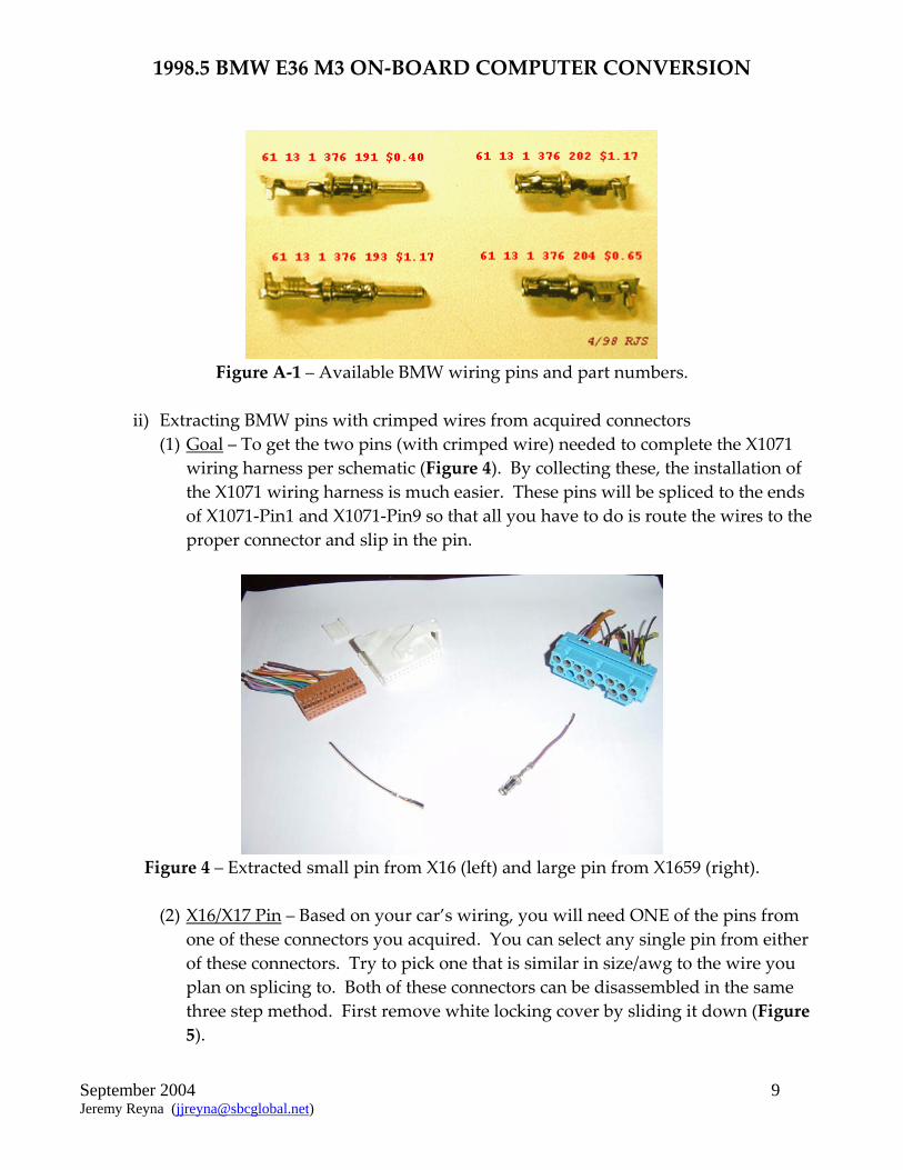
Figure A‐1 – Available BMW wiring pins and part numbers.
ii) Extracting BMW pins with crimped wires from acquired connectors
(1) Goal – To get the two pins (with crimped wire) needed to complete the X1071 wiring harness per schematic (Figure 4). By collecting these, the installation of the X1071 wiring harness is much easier. These pins will be spliced to the ends of X1071‐Pin1 and X1071‐Pin9 so that all you have to do is route the wires to the proper connector and slip in the pin.
Figure 4 – Extracted small pin from X16 (left) and large pin from X1659 (right).
(2) X16/X17 Pin – Based on your car’s wiring, you will need ONE of the pins from
one of these connectors you acquired. You can select any single pin from either of these connectors. Try to pick one that is similar in size/awg to the wire you plan on splicing to. Both of these connectors can be disassembled in the same three step method. First remove white locking cover by sliding it down (Figure 5).

1998.5 BMW E36 M3 ON‐BOARD COMPUTER CONVERSION
September 2004 10 Jeremy Reyna ([email protected])
Figure 5 – Step 1 of 3, Remove locking cover to disassemble connector (X17 shown).
Then press down on button (left forefinger) while pushing white hinge back (right forefinger) (Figure 6).
Figure 6 – Step 2 of 3, Rotate hinge back (X17 shown).
Finally (step 3 of 3), by pulling on the wires, slide the connector out of the shell. It will slide out easily. To pull out the wire and crimped pin, just use a paperclip or equivalent to push down on the pin while simultaneously pulling on the wire (Figure 7). You’ll have to do this twice to completely pull out the wire/pin. Small pin extracted.
1998.5 BMW E36 M3 ON‐BOARD COMPUTER CONVERSION
September 2004 11 Jeremy Reyna ([email protected])
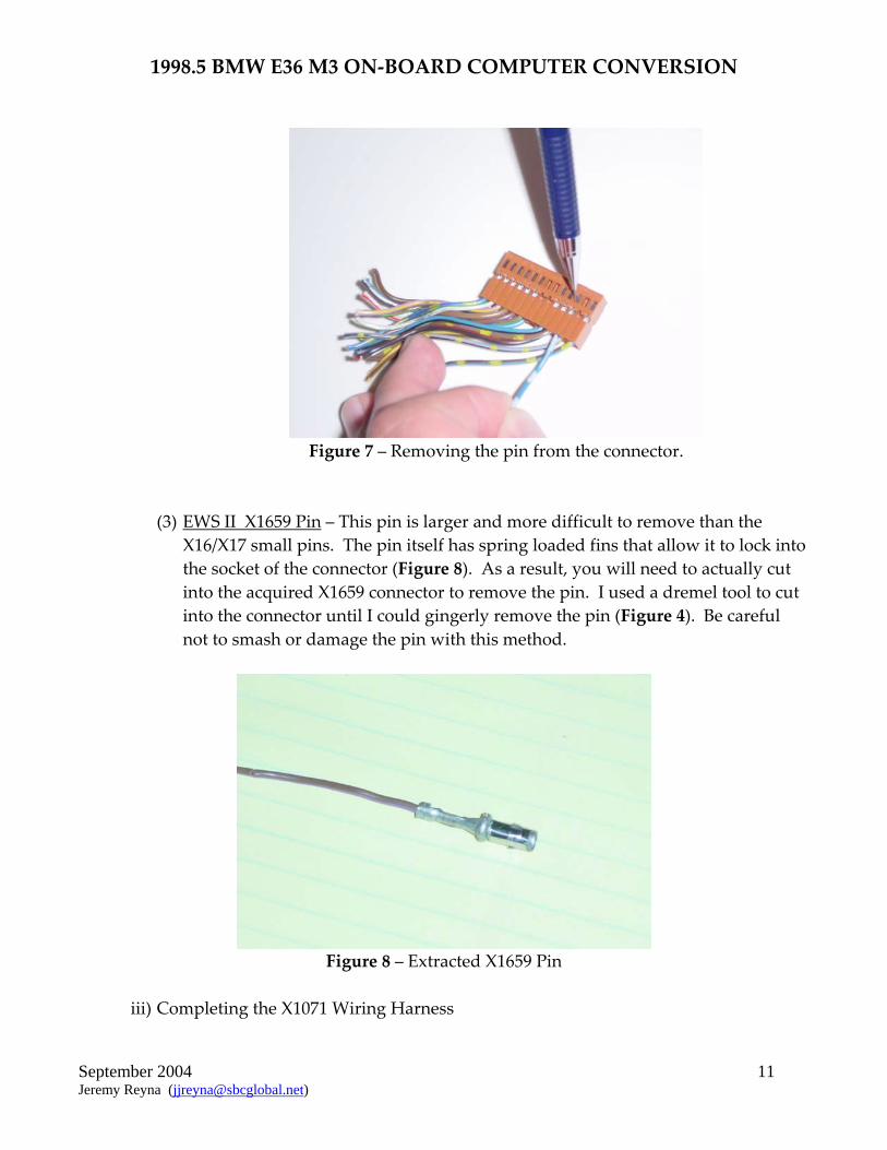
Figure 7 – Removing the pin from the connector.
(3) EWS II X1659 Pin – This pin is larger and more difficult to remove than the X16/X17 small pins. The pin itself has spring loaded fins that allow it to lock into the socket of the connector (Figure 8). As a result, you will need to actually cut into the acquired X1659 connector to remove the pin. I used a dremel tool to cut into the connector until I could gingerly remove the pin (Figure 4). Be careful not to smash or damage the pin with this method.
Figure 8 – Extracted X1659 Pin
iii) Completing the X1071 Wiring Harness
1998.5 BMW E36 M3 ON‐BOARD COMPUTER CONVERSION
September 2004 12 Jeremy Reyna ([email protected])
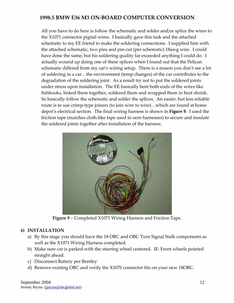
All you have to do here is follow the schematic and solder and/or splice the wires to the X1071 connector pigtail wires. I basically gave this task and the attached schematic to my EE friend to make the soldering connections. I supplied him with the attached schematic, two pins and pre‐cut (per schematic) 18awg wire. I could have done the same, but his soldering quality far exceeded anything I could do. I actually wound up doing one of these splices when I found out that the Pelican schematic differed from my car’s wiring setup. There is a reason you don’t see a lot of soldering in a car…the environment (temp changes) of the car contributes to the degradation of the soldering joint. As a result try not to put the soldered joints under stress upon installation. The EE basically bent both ends of the wires like fishhooks, linked them together, soldered them and wrapped them in heat shrink. So basically follow the schematic and solder the splices. An easier, but less reliable route is to use crimp‐type joiners (to join wire to wire)…which are found at home depot’s electrical section. The final wiring harness is shown in Figure 9. I used the friction tape (matches cloth‐like tape used in oem harnesses) to secure and insulate the soldered joints together after installation of the harness.
Figure 9 – Completed X1071 Wiring Harness and Friction Tape.
6) INSTALLATION
a) By this stage you should have the 18 OBC and OBC Turn Signal Stalk components as well as the X1071 Wiring Harness completed.
b) Make sure car is parked with the steering wheel centered. IE: Front wheels pointed straight ahead.
c) Disconnect Battery per Bentley d) Remove existing OBC and verify the X1070 connector fits on your new 18OBC.

1998.5 BMW E36 M3 ON‐BOARD COMPUTER CONVERSION
September 2004 13 Jeremy Reyna ([email protected])
e) Per Bentley remove trim in driver’s side foot well: kick panel trim, lower dash panel, knee bolster (10mm) and lower steering column trim.
f) Remove Air Bag from Steering Wheel per Bentley 721‐5 i) Wait at least 10 minutes after disconnecting battery before beginning to allow
capacitors to discharge. ii) It helps to tape (3M Blue Painter’s Tape) air bag to steering wheel while removing
the two T30 Torx bolts to prevent it from just falling out. iii) On the back of the airbag are two connectors, one yellow. Pull the yellow one
straight out, normal to surface. The second connector easily removes. g) Remove Steering Wheel per Bentley 320‐1
i) Remove 16mm Bolt and make a mark to align steering wheel to column. Mine already had an alignment mark.
ii) Tighten 16mm bolt with Torque Wrench to 46 ft‐lb (63 Nm) h) Install new OBC Turn Signal Stalk per Bentley 612‐1
i) This step is optional. This part allows you to scroll thru the different functions in the 18OBC using this stalk from the steering wheel column. It is just as easy to reach down and press the buttons on the OBC. Replacing this part requires you to remove the steering wheel, airbag, old turn signal stalk and its wiring harness which is routed down the steering column. Then install this new stalk and route the harness down the steering column to the interfacing connector.
ii) Identify the yellow/red wire that you will later access to splice orange wire from X1071‐Pin4.
i) Remove Instrument Cluster per Bentley 620‐1. It is held in place by two phillip head screws and three connectors. You may be able to access the small connector and X17 blue connector from underneath and behind the instrument cluster. Use Figure 6 for disconnection method of all three connectors.
j) Remove Shift Knob and Boot i) Pull up on one corner of shift boot. ii) Pull up on shift knob.
k) Remove sunglasses pocket, it just prys out once the OBC is removed. You can just move it to the side without disconnecting everything or disconnect everything and completely remove it.
l) Remove Glovebox per Bentley i) Removing the glovebox is not absolutely necessary in my opinion. The ZKE IV
connector is accessible from under the glovebox. See if you can get to it and then if you must remove the glovebox. Be careful with the sheetmetal crossmember under there…it sliced my finger pretty good. One advantage to having the glovebox removed is the ability to cleanly route the wire/lg. pin going to the EWS. The trim panel under the glovebox must be removed. Begin by first removing the passenger side kick panel. Should you decide to remove the glovebox, the Bentley manual fails
1998.5 BMW E36 M3 ON‐BOARD COMPUTER CONVERSION
September 2004 14 Jeremy Reyna ([email protected])
to mention the 10mm bolt under the light cover located on the top of the glovebox pocket. Since I removed the glovebox I decided to go ahead and replace the microfilter (p/n: 64‐11‐9‐069‐895, ~$30).
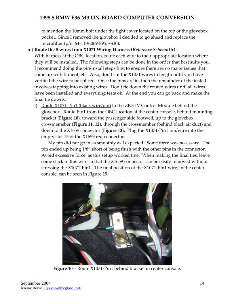
m) Route the 8 wires from X1071 Wiring Harness (Reference Schematic) With harness at the OBC location, route each wire to their appropriate location where they will be installed. The following steps can be done in the order that best suits you. I recommend doing the pin‐install steps first to ensure there are no major issues that come up with fitment, etc. Also, don’t cut the X1071 wires to length until you have verified the wire to be spliced. Once the pins are in, then the remainder of the install involves tapping into existing wires. Don’t tie down the routed wires until all wires have been installed and everything tests ok. At the end you can go back and make the final tie downs. i) Route X1071‐Pin1 (black wire/pin) to the ZKE IV Control Module behind the
glovebox. Route Pin1 from the OBC location at the center console, behind mounting bracket (Figure 10), toward the passenger side footwell, up to the glovebox crossmemeber (Figure 11, 12), through the crossmember (behind black air duct) and down to the X1659 connector (Figure 13). Plug the X1071‐Pin1 pin/wire into the empty slot 15 of the X1659 red connector.
My pin did not go in as smoothly as I expected. Some force was necessary. The pin ended up being 1/8” short of being flush with the other pins in the connector. Avoid excessive force, as this setup worked fine. When making the final ties, leave some slack in this wire so that the X1659 connector can be easily removed without stressing the X1071‐Pin1. The final position of the X1071‐Pin1 wire, in the center console, can be seen in Figure 19.
Figure 10 – Route X1071‐Pin1 behind bracket in center console.

1998.5 BMW E36 M3 ON‐BOARD COMPUTER CONVERSION
September 2004 15 Jeremy Reyna ([email protected])
Figure 11 – Route wire up and to glove box cross‐member.
Figure 12 – Continue routing in cross‐member behind vent duct.

1998.5 BMW E36 M3 ON‐BOARD COMPUTER CONVERSION
September 2004 16 Jeremy Reyna ([email protected])
Figure 13 – Route to empty Pin15 of X1659 Connector.
ii) Route X1071‐Pin4 (orange wire) to the OBC Stalk Harness located under the dash
near the lower steering column. Route the orange wire from the OBC location at the center console toward the the driver’s side footwell (Figure 14), behind oem harness clip (Figure 15), toward firewall, around and then up lower steering column.
Figure 14 – Route X1071‐Pin4 toward driver’s side footwell on left side of console.
1998.5 BMW E36 M3 ON‐BOARD COMPUTER CONVERSION
September 2004 17 Jeremy Reyna ([email protected])
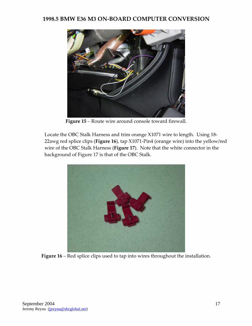
Figure 15 – Route wire around console toward firewall.
Locate the OBC Stalk Harness and trim orange X1071 wire to length. Using 18‐22awg red splice clips (Figure 16), tap X1071‐Pin4 (orange wire) into the yellow/red wire of the OBC Stalk Harness (Figure 17). Note that the white connector in the background of Figure 17 is that of the OBC Stalk.
Figure 16 – Red splice clips used to tap into wires throughout the installation.

1998.5 BMW E36 M3 ON‐BOARD COMPUTER CONVERSION
September 2004 18 Jeremy Reyna ([email protected])
Figure 17 – Orange wire tapped to OBC Stalk Harness and secured with tiewraps.
iii) Route X1071‐Pins5 (violet wire), X1071‐Pin6 (white wire) and X1071‐Pin7 (yellow
wire) to X16 Instrument Cluster harness and white connector. Route the wires from the OBC location at the center console using the same path as described for X1071‐Pin 4 (orange wire) in Figures 14 and 15. Pull the X16 harness as far down into the footwell as you are willing or able. Trim the X1071‐Pin5, 6 and 7 wires to length, including slack to allow the X16 harness to return to original position. Using red splice clips tap X1071‐Pin5 (violet wire) into the white/violet wire of X16 connector. Then tap X1071‐Pin6 (white wire) into the white/black wire of the X16 connector. Finally tap X1071‐Pin7 (yellow wire) into the white/yellow wire of the X16 connector (Figure 18).

1998.5 BMW E36 M3 ON‐BOARD COMPUTER CONVERSION
September 2004 19 Jeremy Reyna ([email protected])
Figure 18 – Taps to X16 harness shown in center of picture (OBC stalk tap shown to right).
While you can make the connections just behind the X16 connector at the instrument cluster, it is cleaner to tap into the X16 harness further down the harness away from the X16 connector. Note that the X16 wiring harness goes through a wire tie that is fixed to the upper dash area. It is pretty difficult to access this tie. While the harness itself can slip through the tie, the red splice clips you tapped into the harness will not. Tap too close to the X16 connector and you will not be able to pull the harness back up to its original position which will in turn make plugging the X16 connector into the instrument cluster even more difficult or impossible.
IMPORTANT: Depending on your cars wiring scheme one or more of the three X16 wires, that required tapping in my car, may be missing. If the wire you want to tap into is missing, add a pin and plug it into the appropriate pin# in the X16 connector. For a 98 M3: white/violet wire = X16‐Pin12; white/yellow wire = X16‐Pin11; white/black wire = X16‐Pin21.
iv) Route X1071‐Pin 8 (red wire) and X1071‐Pin13 (brown wire) to the X1070 OBC harness and black connector. Route the two wires from the OBC location at the center console down the X1071 wiring harness and then back up the X1070 wiring harness (Figure 19). Trim the X1071‐Pin8 and Pin13 wires to length. Using the red splice clips, tap X1071‐Pin8 (red wire) into the red/yellow wire of X1070 harness (pin18). Then tap X1071‐Pin13 (brown wire) into the brown wire of X1070 (pin17). These are the power (red) and ground (brown) wires.
Figure 19 – Pins 8 and 13 of X1071 connector routed and tapped with red splice clips into
X1070 connector.

1998.5 BMW E36 M3 ON‐BOARD COMPUTER CONVERSION
September 2004 20 Jeremy Reyna ([email protected])
v) Route X1071‐Pin9 (gray wire/pin) to the X17 Instrument Cluster harness and blue
connector. Route the two wires from the OBC location at the center console using the same path as described for X1071‐Pin 4 (orange wire) in Figures 14 and 15. Then continue to route the X1071‐Pin9 wire/pin up to the instrument cluster area and plug the pin/wire into the empty slot 10 of the X17 blue connector.
n) Plug X1071 and X1070 connectors into 18 button OBC o) Per Bentley, re‐install steering wheel and air bag. Install is reverse of removal. p) Re‐connect battery (13mm socket) q) Turn ignition on and the 18 OBC should light up and ask you to input the time. r) Verify OBC Turn Signal cycles through OBC functions. s) Once you are satisfied, turn off ignition and begin to tie down all the wires to their final
position. Figure 20 and 21 shows some of the final routing tie downs and positions of the X1071 wiring harness leaving the center console.
Figure 20 – X1071 harness and white connector installed.

1998.5 BMW E36 M3 ON‐BOARD COMPUTER CONVERSION
September 2004 21 Jeremy Reyna ([email protected])
Figure 21 – X1071 wiring harness tied down in final position.
t) YOU’RE DONE!!
7) ATTACHMENTS

1998.5 BMW E36 M3 ON‐BOARD COMPUTER CONVERSION
September 2004 24 Jeremy Reyna ([email protected])
ATTACHMENTS •BMW ON BOARD COMPUTER RETROFIT/CONVERSION
By: Lars Staack (email: lkstaack @ hotmail.com)
I successfully swapped out my 11‐Button OBC for an 18‐Button in my 98 M3, and it wasn’t that hard. All functions work, including the hidden ones. Anyone with moderate mechanical skills can complete this conversion; I give it a two‐½ wrench out of five difficulty level. Much quicker and a little easier than installing VDO gauges. I’m an idiot, so it couldn’t have been that tough. Special recognition should be given to ʺBiMmEr JoNʺ who made the original OBC Conversion post on Bimmerforums (http://www.bimmerforums.com/forum/s...c%2A+conversion) and whose collaboration made my retrofit possible.
The conversion isnʹt specifically targeted to only early E36s. In fact, some of the OBC functions wonʹt work on pre‐94 E36s because they donʹt have the ZKE type security system. The 18 button OBC was an option for all year E36s that most, but not all, buyers requested. The conversion is targeted for BMWs that didnʹt get the option.
I wanted a full OBC when I was shopping for an M3. When I finally found a used one that wasn’t thrashed, I was very disappointed that it only had the enhanced clock OBC. What can I say? I love gadgets. When I started researching the possibility of converting a full OBC into my Bimmer, everything I read said either: “a swap is not possible, buy a car with it installed”, or, “you can retrofit an 18‐Button OBC, but it will require you to tear your interior apart, install sensors, and run long runs of wire…it is not worth the hassle”. Wrong! Wrong! Wrong! This is how I did it.
First, I have to note a few disclaimers:1. This procedure worked on my 98 M3. There is no guarantee that it will work on your BMW. The Bentley manual notes two E36 OBC diagrams: 1992‐1997 (non‐318ti) and 1998 (non‐318ti). The 1992‐1997 diagram is slightly different. Also, the ZKE IV wasn’t available until 1994. However, you should be able to modify these instructions to make it work on your car. 2. In the interest of brevity, I am assuming that you know, or will be able to get instructions to remove:
OBC 2‐ Airbag and Steering Wheel (you can really hurt yourself if you don’t follow safety procedures) 3‐ Instrument Cluster 4‐ Glove Box.
I am also assuming that you will be able to figure out some sub‐procedures that I will not mention, but should be obvious.
As ʺBiMmEr JoNʺ noted in his post, you will need a working 18‐Button OBC and the white X1071 connector that the 11‐Button OBC doesn’t have. Also get an OBC controller turn signal stalk if you want to control the OBC with it. I ordered my OBC and connectors from an import salvage yard over the phone. I strongly recommend that you use a Bentley Manual. Even though some of the electrical diagrams are not perfect, it will pay for itself many times over in time saved.
1998.5 BMW E36 M3 ON‐BOARD COMPUTER CONVERSION
September 2004 25 Jeremy Reyna ([email protected])
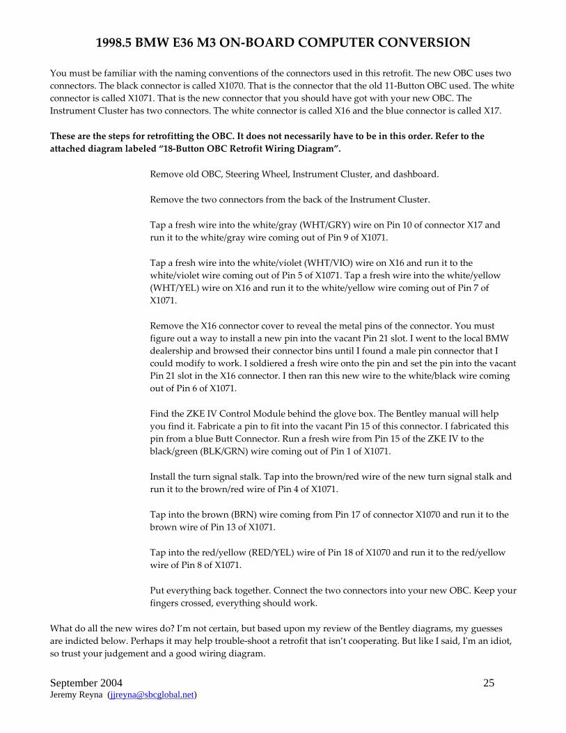
You must be familiar with the naming conventions of the connectors used in this retrofit. The new OBC uses two connectors. The black connector is called X1070. That is the connector that the old 11‐Button OBC used. The white connector is called X1071. That is the new connector that you should have got with your new OBC. The Instrument Cluster has two connectors. The white connector is called X16 and the blue connector is called X17.
These are the steps for retrofitting the OBC. It does not necessarily have to be in this order. Refer to the attached diagram labeled “18‐Button OBC Retrofit Wiring Diagram”.
Remove old OBC, Steering Wheel, Instrument Cluster, and dashboard.
Remove the two connectors from the back of the Instrument Cluster.
Tap a fresh wire into the white/gray (WHT/GRY) wire on Pin 10 of connector X17 and run it to the white/gray wire coming out of Pin 9 of X1071.
Tap a fresh wire into the white/violet (WHT/VIO) wire on X16 and run it to the white/violet wire coming out of Pin 5 of X1071. Tap a fresh wire into the white/yellow (WHT/YEL) wire on X16 and run it to the white/yellow wire coming out of Pin 7 of X1071.
Remove the X16 connector cover to reveal the metal pins of the connector. You must figure out a way to install a new pin into the vacant Pin 21 slot. I went to the local BMW dealership and browsed their connector bins until I found a male pin connector that I could modify to work. I soldiered a fresh wire onto the pin and set the pin into the vacant Pin 21 slot in the X16 connector. I then ran this new wire to the white/black wire coming out of Pin 6 of X1071.
Find the ZKE IV Control Module behind the glove box. The Bentley manual will help you find it. Fabricate a pin to fit into the vacant Pin 15 of this connector. I fabricated this pin from a blue Butt Connector. Run a fresh wire from Pin 15 of the ZKE IV to the black/green (BLK/GRN) wire coming out of Pin 1 of X1071.
Install the turn signal stalk. Tap into the brown/red wire of the new turn signal stalk and run it to the brown/red wire of Pin 4 of X1071.
Tap into the brown (BRN) wire coming from Pin 17 of connector X1070 and run it to the brown wire of Pin 13 of X1071.
Tap into the red/yellow (RED/YEL) wire of Pin 18 of X1070 and run it to the red/yellow wire of Pin 8 of X1071.
Put everything back together. Connect the two connectors into your new OBC. Keep your fingers crossed, everything should work.
What do all the new wires do? I’m not certain, but based upon my review of the Bentley diagrams, my guesses are indicted below. Perhaps it may help trouble‐shoot a retrofit that isn’t cooperating. But like I said, Iʹm an idiot, so trust your judgement and a good wiring diagram.

1998.5 BMW E36 M3 ON‐BOARD COMPUTER CONVERSION
September 2004 26 Jeremy Reyna ([email protected])
White/Gray wire: connects OBC to speedometer sensor
White/Violet and White/Yellow wires: connects OBC to data link system. This system integrates most of the electronic boxes such as ABS, Cruise Control, EWS, ZKE, DME, OBC, etc.
White/black wire: connects OBC to gas gauge
Black/Green: connects OBC to AWS anti‐theft device
Brown/Red: grounds OBC for turn signal stalk activated menu display
Brown: Ground
Red/Yellow: Power
Good luck! And donʹt listen to people who say it canʹt be done. They donʹt know what theyʹre talking about.

1998.5 BMW E36 M3 ON‐BOARD COMPUTER CONVERSION
September 2004 28 Jeremy Reyna ([email protected])
MISCELLANEOUS
•REMOVING OBC: Put your hand in the sunglass holder face up. With you fingers feel around the top of the holder for a small circular hole. Stick your index and fore fingers in the hole (if they both fit) and push the bottom of the OBC up and out. If all goes well, the bottom of the OBC should tilt towards you about 1/4 inch. Now, with you free hand, try to pull on the OBC so that the top part comes out about a quarter of an inch also. The OBC should now be about 1/4 inch out on all sides. Grab it with both hands and pull it up and out. NOTE: there is a a small tab centered on the bottom plane of the OBC about 1/4 inch back. You will need to make sure that tab clears the top of the sunglass holder in order to get it out (it may seem impossible but with a little effort, it will come out). To remove the sunglass holder slide it up (in the void where the OBC used to be) and pull it out. Installation is the reverse of removal :)
8)
1998.5 BMW E36 M3 ON‐BOARD COMPUTER CONVERSION
September 2004 29 Jeremy Reyna ([email protected])
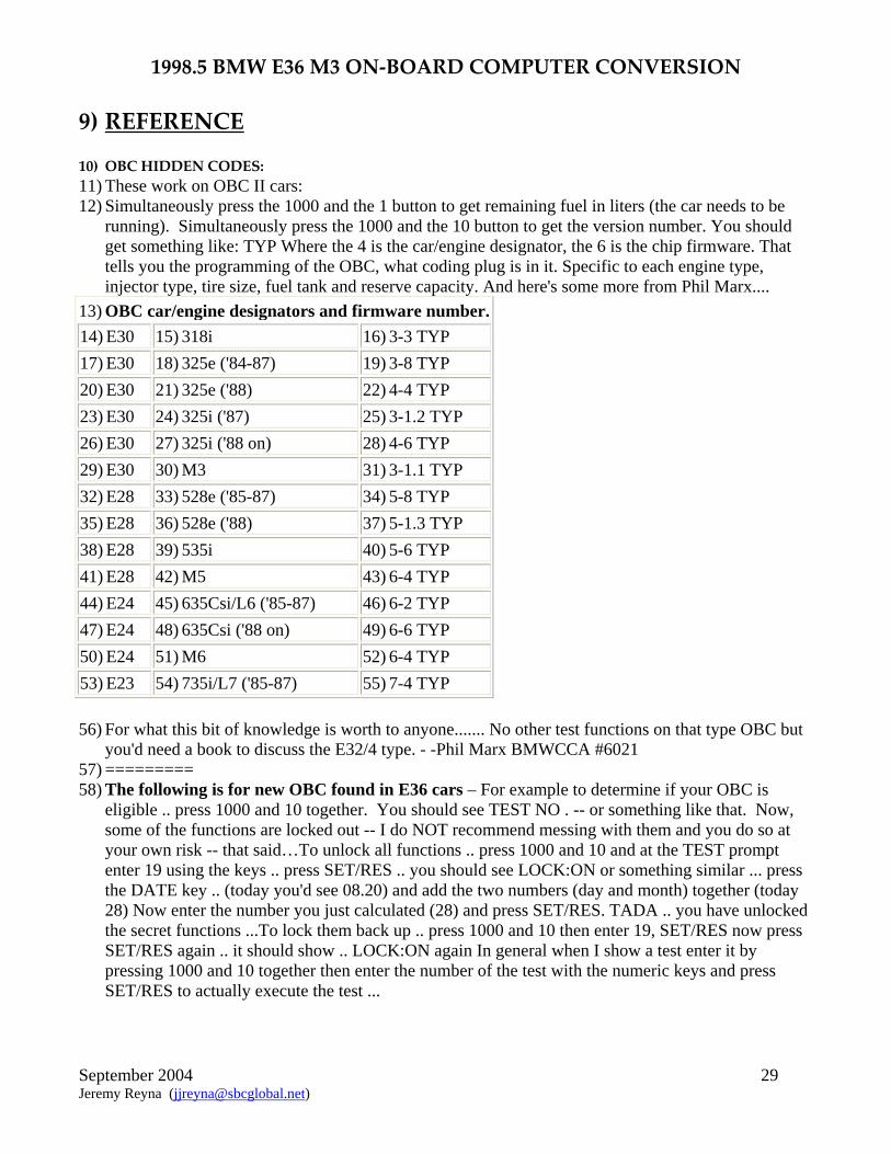
9) REFERENCE 10) OBC HIDDEN CODES: 11) These work on OBC II cars: 12) Simultaneously press the 1000 and the 1 button to get remaining fuel in liters (the car needs to be
running). Simultaneously press the 1000 and the 10 button to get the version number. You should get something like: TYP Where the 4 is the car/engine designator, the 6 is the chip firmware. That tells you the programming of the OBC, what coding plug is in it. Specific to each engine type, injector type, tire size, fuel tank and reserve capacity. And here's some more from Phil Marx....
13) OBC car/engine designators and firmware number. 14) E30 15) 318i 16) 3-3 TYP 17) E30 18) 325e ('84-87) 19) 3-8 TYP 20) E30 21) 325e ('88) 22) 4-4 TYP 23) E30 24) 325i ('87) 25) 3-1.2 TYP 26) E30 27) 325i ('88 on) 28) 4-6 TYP 29) E30 30) M3 31) 3-1.1 TYP 32) E28 33) 528e ('85-87) 34) 5-8 TYP 35) E28 36) 528e ('88) 37) 5-1.3 TYP 38) E28 39) 535i 40) 5-6 TYP 41) E28 42) M5 43) 6-4 TYP 44) E24 45) 635Csi/L6 ('85-87) 46) 6-2 TYP 47) E24 48) 635Csi ('88 on) 49) 6-6 TYP 50) E24 51) M6 52) 6-4 TYP 53) E23 54) 735i/L7 ('85-87) 55) 7-4 TYP
56) For what this bit of knowledge is worth to anyone....... No other test functions on that type OBC but you'd need a book to discuss the E32/4 type. - -Phil Marx BMWCCA #6021
57) ========= 58) The following is for new OBC found in E36 cars – For example to determine if your OBC is
eligible .. press 1000 and 10 together. You should see TEST NO . -- or something like that. Now, some of the functions are locked out -- I do NOT recommend messing with them and you do so at your own risk -- that said…To unlock all functions .. press 1000 and 10 and at the TEST prompt enter 19 using the keys .. press SET/RES .. you should see LOCK:ON or something similar ... press the DATE key .. (today you'd see 08.20) and add the two numbers (day and month) together (today 28) Now enter the number you just calculated (28) and press SET/RES. TADA .. you have unlocked the secret functions ...To lock them back up .. press 1000 and 10 then enter 19, SET/RES now press SET/RES again .. it should show .. LOCK:ON again In general when I show a test enter it by pressing 1000 and 10 together then enter the number of the test with the numeric keys and press SET/RES to actually execute the test ...

1998.5 BMW E36 M3 ON‐BOARD COMPUTER CONVERSION
September 2004 30 Jeremy Reyna ([email protected])
59) Test numbers for E36 OBC (Note: Joe this should also work for your 535!) 60) Test no. 61) Description
62) 1 63) Display Test .. all LCDs and LEDs activate 64) 2 65) Current Consumption in l/100km 66) 3 67) Current Consumption in l/hour 68) 4 69) Average Consumption (used to calc. Range) 70) 5 71) Current Range 72) 6 73) Not used .. 74) 7 75) Average Fuel in Tank (l) 76) 8 77) Current Speed (km/h) 78) 9 79) System Voltage at terminal R 80) 10 81) Country/Language 82) 11 83) Units/ AM.PM 84) 12 85) Average Speed (km/h) for calc. ETA 86) 13 87) ETA 88) 14 89) Date of software/mask of OBC 90) 15 91) Production Diagnosis (??) 92) 16 93) Production Diagnosis (??) 94) 17 95) Display Vehicle Specific Data 96) 18 97) Alarm Changeover (continuous v. intermittent) 98) 19 99) LOCK/UNLOCK all functions
100) 20 101) Correction Factor for OBC Fuel Consumption (SEE BELOW!) 102) 21 103) Reset all defect codes, date and time ... activate by pressing SET/RES
104) 105)
106) Note on test #20:
107)
108) The factor is used to correct the OBC Avg Fuel Consumption figure to reality. If your OBC is off a bit: fill UP totally, run tank down and refill; then calculate your Actual MPG. Now enter test 20 to get the old Correction Factor.
109) NEW CF= OLD CF *(OBC MPG/Actual MPG) 110) Enter the NEW CF using the numeric keys and hit SET/RES to store. PLEASE
record your OLD CF so that IF you screw up you can always go back to what it was.
111) ================== 112) Updates:

1998.5 BMW E36 M3 ON‐BOARD COMPUTER CONVERSION
September 2004 31 Jeremy Reyna ([email protected])
113) This is from a European 1990 M5 owner (9/3/96): I have also found a deviation from the FAQ (which describes an E36 OBC) in the 'lock/unlock secret functions' of the E34 OBC: To unlock:
114) Press the DATE key, and add the day + month numbers 115) Press 1000 and 10 simultaneoulsy, then use 10 and 1 keys to enter test 19 116) Press S/R once. You will now see 0000LOCK or similar 117) Use the 10 and 1 keys to enter the sum of day + month 118) Press S/R -- secret functions are unlocked... 119) Verify by entering test 19 again. Display should show FREE 120) To lock: 121) Press 1000 and 10 simultaneoulsy, then use 10 and 1 keys to enter test 19 122) Press S/R once. You will now see FREE or similar 123) Press the little square button (F/C) to the left of display 124) Verify by entering test 19 again. Display should be 0000LOCK. 125) The procedure to show the version number also differs from the FAQ. On the E34 OBC, you
need to press the 100 and 1 buttons simultaneously, to display the type/version (Mine shows '5-00TYP').

1998.5 BMW E36 M3 ON‐BOARD COMPUTER CONVERSION
September 2004 32 Jeremy Reyna ([email protected])
126) FIXING THE BACKLIGHT 127) This is about a 1988 325is, but many other models are similar. A variation of this note appeared
in the Feb., 1994 Roundel and is included in the "BMW Enthusiasts Companion" book published by Bentley. The backlight for the OBC display is provided by a pair of small incandescent bulbs which are soldered to a small printed circuit board. This board is in a white plastic housing that slides into the right side of the OBC. The bulb assembly cost about $20.00 from the dealer. A resourceful hack mechanic could save 20 bucks by unsoldering the old bulb and soldering in a new one. You probably would have a hard time finding an exact replacement bulb but you could find one close enough.
128) Added. 11/2/94 - The bulbs are 5 Volt and use about 80 mA. The nearest Radio Shack bulbs are: part number 272-1140, 6 volt. They can be soldered right in the circuit board. The hard part is getting at the side of the OBC to remove the bulb holder without disassembling the entire center console. You must partially remove the center console panel. The OBC is screwed into the center console panel from the rear with 4 phillips screws. Once the screws are out, it comes out toward the rear (unfortunately!!). First I removed the radio by loosening the screws that lock it into the center console. These screws are a special 5 sided torx-like screw that require a special tool to remove properly. The tool costs something like $15.00 at the dealer, but you can usually get by with a 2mm hex wrench. It's really maddening that of all the worhtless crap in the BMW toolbox that comes with the car, they cant put this $0.50 tool in. The hex wrench might chew up the screw a little bit, but it will still work repeatedly. I did all this with the battery connected so I didn't have to reset codes or reprogram the computer. No electrical connectors have to be removed so there's not much danger of shorting things. The radio has long enough wires that you can pull it out the front and rest it on the ashtray while you do the rest. The Bentley manual really helped on the next step because it showed the location of the screws that hold the center panel. There are 2 #1 Phillips screws at the top, behind the hazard flasher switch, which you have to pull out and leave dangling by the wires, the other behind the dummy plug. The 2 #2 Phillips screws at the bottom are harder to reach--you need a short screwdriver--but they're not that tough. Once the four screws are out you can pull the center console out enough to access the computer. You have to be careful not to snap off plastic edges, slide the panel to the right as you pull to free the lip on the left side. Note that everything (heater controls, radio balance control, etc.) is still connected to the center console. This makes it a little harder to maneuver, but it's a lot less work in the end. [See below for alternate method to removing bottom console screws.] If your wrist is small enough, you can reach in through the radio opening and loosen the 2 Phillips screws that hold the left side of the OBC. You don't need to remove the screws, just loosen them. If you can't fit through the radio opening, you'll have to remove the glove box and side panels to reach the screws from behind. Now with the left side loose you just need to pull the right side of the center panel out about 2 inches until you can access the left side screws. At this point you can see the flush mounted bulb-holder and you realize that this thing was not very well engineered! The center panel cutout blocks access to the slide out bulb-holder. That is why you have to remove the 2 screws holding the left side of the computer. It would have been an easy matter to design a center console that didn't block the bulb. For that matter, it seems it would have been easy to design a computer mount that allowed it to just snap out toward the front or screw out like the radio. The bulb could then be changed in 30 seconds. Back to the 2 left side screws--to really get a screwdriver on these you would have to pull the center panel out at least 4 or 5 inches. It didn't seem like it wanted to be pulled out that far without removing more stuff (like heater controls) so instead I just opened it enough to get a pair of small needle nose vise-grips on the heads of the screws. They aren't in very tight so with a little patience the vise-grips remove the screws.

1998.5 BMW E36 M3 ON‐BOARD COMPUTER CONVERSION
September 2004 33 Jeremy Reyna ([email protected])
129) [Addition from Rick Kjeldsen - The center panel will come completely off the heater if you do the following: Take (pull) off the caps from the 3 heater slider controls. There is a thin plastic cover over the three slider slots that covers 4 screws. It is about the size of a 3x5 card. You have to gently pry it off to avoid damaging it. I found I can pull from one of the slider slots to get it started. That will uncover 4 screws that hold the center panel to the heater core.]
130) Now the on-board computer can be pushed in from the center panel, the bulb-holder pulled out and the new one slips right in. I checked the old bulbs and sure enough one was burned out (they're in series so this takes out the other one). Just to make sure before I closed everything up, I stuck in the key, turned on the ignition and the correct time of day lit up beautifully! I just reversed the procedure to get everything back. The biggest problem here was restarting the 2 bottom screws on the center panel. It's impossible to see anything and there isn't enough room even for my small hands. A little patience will get you there though.
131) [11/5/93 Update - You might be able to get away with this easier method, supplied by Kent Shephard which worked on his M3]
132) My mechanic showed me how to do this on my M3 today and he said this description is *NOT* the way a flat rate mechanic does it. He works for a dealership and he did my M3 is all of 10 minutes. So folks I'll outline it so the FAQ can be changed. He said all the screws don't need to come out. He said this description is for those obsessed with getting the computer out. So follow along. a) DO NOT REMOVE THE BOTTOM SCREWS *
133) At this point tilt the top of the console forward. Don't be scared you won't break it. You will now be able to look on the right side of the computer and see the light module and a single screw. You will need the needle nose pliers to remove that screw. It has fine threads so be patient. Throw screw away. The computer will hold fine with three screws. After the screw is out, pull the module with the needle nose pliers and it will come out. Now slide the new one in and reassemble.
134) ======================== 135) MORE EXAMPLES:
i) Here is another person's experience. Note this is in conflict with the above--namely in that the OBC comes out toward the front and is held in by nuts not phillips screws. Maybe BMW used different methods. I think sometime in the early 90's the OBC does snap out toward the front simply by prying with a credit card. (can somebody verify this and e-mail me. (by Mike Whitley: [email protected]) A lot of people have complained about the backlight on the E30 onboard computer. When I had a 325is, the lights burned out. Replacing the little panel or even just the bulbs is an easy job. Saves you $70 or $80 as well compared to letting a dealer do it. A quick summary follows.
136) Access the computer... this involves first taking out the glove box, and right side dash board cover. Everything is held in place by push pins, they just twist and pull out.
137) Now, you need a socket wrench, with a short handle and a very small socket. I can't remember how big... anyway, use the wrench to undo the nuts that hold the computer in place on the dash baord. You won't be able to see them just feel around and you will find them. Once the nuts have been removed, the computer will slide out of the dash towards the seats.
138) On the side of the computer is a small white panel. This is the back light bar. Pry it out with a small screwdriver or fingernail and pop in the new one. If spending $25 or $30 for this seems like a waste of money to you, desolder the dead bulbs and solder in new ones for about $2.00. They may not have the exact same wattage though. If the computer push buttons have also stopped lighting up, the bulb for that is located in the back. Twist it out and pop in a new one. (You remembered to pick one up at your dealer right?)

1998.5 BMW E36 M3 ON‐BOARD COMPUTER CONVERSION
September 2004 34 Jeremy Reyna ([email protected])
139) Reverse the installation instructions and voila! You are done. The whole thing shouldn't take more than two hours. Less if you are quick.
i) By Steve Fox: [email protected] Alternate method: Remove radio (easy). Pop top switches above radio (easy). Remove two phillips screws at top of center console. They will be visible through the recently vacated switch holes (easy). Remove two phillips screws at bottom of center console, just under bottom edge (easy). Pull center console forward on the right edge exposing the business side of OBC (easy, but gently, not much distance needed). Remove top right nut that secures OBC (easy). Trim pointless plastic interfering with removal of light bar (easy, makes next replacement even easier). Pull out light bar with needle nose and replace with new unit (easy). Assemble in reverse order of disassembly (easy).
140) I did this in 20 minutes the first time. The other method on this list (through the glove box) sounds great too but I could not contort my fingers enough to remove the four OBC nuts. Local dealer wants about $80 for this procedure.

1998.5 BMW E36 M3 ON‐BOARD COMPUTER CONVERSION
September 2004 35 Jeremy Reyna ([email protected])
141) What to do if you get PPPP displayed on the OBC 142) I've heard that disconnecting the battery for a long time (like 1 hour) will make this go away. I
lived with this problem for several (3) years. I tried disconnecting the battery for the 1+ hours or so to no avail. The ultimate solution was to disconnect the computer itself from its multi-pin connector. I left it unhooked for approximately 24 hours. Upon reconnecting the computer.....viola a full up and running OBC II. Jeff Wilcox
143) So here is what works most of the time: With the key in the "Radio" position (Radio and OBC
light up, but not the instrument cluster), press the "CODE" button. Then push the little reset-hole with a Pen and hold it, 'till the computer blinks in the display, and it will ask you for a time and date entry. - You now have re-adapted the coding plug to the computer. - Normally the computer goes into a PPPP mode when the car has been boosted, or some other very drastically voltage changes have occurred.
1/06/2005 – Someone wrote me with this problem. He eventually tried a new OBC and it worked fine afterwards. Seems the original obc was faulty.

1998.5 BMW E36 M3 ON‐BOARD COMPUTER CONVERSION
September 2004 36 Jeremy Reyna ([email protected])
144) E36 On-Board Computer (OBC) Hidden Codes and Tests 145) There are many interesting functions available on the E36 OBC that are not documented in the owner's
manual, including changing the language of the display. The procedures described here work on my '97 328iC, which has the upgraded OBC - they may work on other models of similar vintage. There are some links at the bottom of the page for information on other OBCs, and for setting the language if you don't have the OBC. You can also find information on hidden tests for the instrument panel.
146) Contents: 147) Programming the Display Order 148) Accessing Data 149) Unlock the Display 150) Test Codes 151) Setting the Country Code 152) Other OBCs 153) Programming the OBC to Display Contents in a Desired Order 154) When you repeatedly press in on the turn signal stalk, the OBC display cycles through the various
information types that it has in memory. The default sequence is: CONSUM1, CONSUM2, EXT. TEMP, SPEED, LIMIT, DIST and TIMER. If you want to change the display order, use the following procedure:
155) Press in and hold the turn stalk for about 5 seconds. The OBC display will change to Prog 1. Press the button corresponding to the first function you would like to have displayed in the sequence. For example, if you would like the outside temperature to be displayed first, press the TEMP button. The display will then change to Prog 2. Continue pressing the OBC buttons in the order you want, up through nine entries. You don't have to enter all nine - if you would like the display to cycle only between TEMP and RANGE, simply enter those two items as Prog 1 and Prog 2. When finished, press the SET/RES button to store the sequence in memory.
156) To revert to the default order, simply press SET/RES as soon as Prog 1 is displayed. 157) Accessing Data in the OBC 158) The OBC contains a lot of data, and displays the data in a manner determined by the country code that is
stored in it. The technique to access this data is as follows: 159) Press the 1000 and 10 keys simultaneously. You should see Test-Nr.: appear in the display. 160) The table below lists the available test codes that are available. Enter a test code number, using the
number keys, followed by the SET/RES key. However, to access codes other than 1, 10, 14, 19, and 21, you have to first unlock the OBC, using the procedure described below.
161) Read the results. 162) For test numbers 10 and 11, enter a new value (if desired) and press SET/RES. 163) Return to the normal display functions by pressing CHECK or any other key. 164) Unlock the Display. Most of the test sequences require you to first unlock the display before. Enter test
code 19 using the above procedure. The display should read LOCK: ON. Then enter an unlocking code consisting of the sum of the current month plus date (for example, if today is July 11, enter 18). Then press SET/RES, and the OBC is now unlocked.
165) Test Codes. Following is a listing of the available tests, along with with my notes as to what I think each test means. Note that the display uses European conventions for decimals (i.e., the number 61,7 is 61.7 for us Americans). You will see that I don't have good explanations for several of these test codes -- if you have any information that can help me make this table more complete, please email me at [email protected].
166) Test Code No.
167) Display 168) Notes
169) Display Must Be Unlocked
First? 170) 01 171) All LED 172) Verify that the display is working 173) No

1998.5 BMW E36 M3 ON‐BOARD COMPUTER CONVERSION
September 2004 37 Jeremy Reyna ([email protected])
display elements are lit
properly
174) 02 175) VBR: n,n l/100km
176) n,n = instantaneous fuel usage in liters/100 km 177) Yes
178) 03 179) VBR: n,n l/h 180) n,n = instantaneous fuel usage in liters per hour 181) Yes
182) 04 183) RW-VBR: n,n l/100
184) n,n = average fuel usage in liter/100 km. 185) Yes
186) 05 187) RW: nnn km 188) nnn = range in km 189) Yes 190) 06 191) -- 192) Not used 193) Yes
194) 07 195) TMTL: nn,n l 196) nn,n = fuel remaining (in liters) 197) Yes
198) 08 199) V: n km/h 200) n = instantaneous speed in km/h 201) Yes
202) 09 203) UB: nn,nn V 204) nn,nn = system voltage (should be around 13,80) 205) Yes
206) 10 207) LAND: n xxx *
208) Country code -- for US drivers should be set to 2 USA -- see description below
209) No
210) 11 211) EINHEIT n: xx *
212) ?? There are two EINHEIT displays: the values for xx in EINHEIT 1 can range between B0 and BF, and for EINHEIT 2 range between 0F and FF (mine is set to B3 and FF, respectively). Press the 1000 or 100 key to switch between EINHEIT 1 and EINHEIT 2.
213) Yes
214) 12 215) VANK nn km/h 216) nn = average speed 217) Yes
218) 13 219) ANK: nn:nn 220) nn:nn = ETA (will display --:-- if
the OBC's distance function is not in use)
221) Yes
222) 14 223) ROM: dd.mm.yy
224) dd.mm.yyyy = Software version date. Mine is 25.06.1991 225) No
226) 15 227) DIAG: nn nn nnn xx
228) Diagnosis code? Mine is 01 05 255 FA 229) Yes
230) 16 231) PORT: nn nnnnnnnn
232) Port codes? Press 1000 or 100 key to cycle port numbers. For example, PORT 01 is 10101000
233) Yes
234) 17 235) PROM: nn nn 236) ?? Mine reads 00 12 237) Yes

1998.5 BMW E36 M3 ON‐BOARD COMPUTER CONVERSION
September 2004 38 Jeremy Reyna ([email protected])
238) 18 239) HORN: xxxx
240) DTON or DTOFF? (Single tone horn versus dual tone) 241) Yes
242) 19 243) LOCK: xx 244) xx = ON or OFF. See description above for method. 245) No
246) 20 247) KVBR: nnnn 248) nnnn = Fuel rate calibration factor. Mine is set to 1000 249) Yes
250) 21 251) RESET?
252) Reset all defect codes? Also erases all stored values in the OBC (i.e, fuel consumption, avg. speed, timer, etc) and clock.
253) Yes
254) Setting the Country Code. If your OBC suddenly starts displaying everything in German, and you would like to put it back to English, use test sequence number 10. Once you're into test number 10, press the 1 key several times, and you'll see the display cycle through various country options. For example, 0 is for Germany (the display reads LAND: 0 D * - I assume D stands for Deutschland). As you cycle through the options, you'll see choices for the Great Britain, USA, France, Canada, etc. Once the display is on the country you want, press the SET/RES key to store your choice into memory -- for US drivers the display should be set to LAND: 2 USA * . Then press the CHECK key, and the display will reflect the units of the country you've chosen.
255) Information on other OBCs: 256) If your E36 is not equipped with the upgraded OBC, you can reset the language of the display using the
procedure on the Language Page. 257) I have information on the E28 OBC. 258) Here is a link to a page that covers the OBC for the E32 7-series.: http://home.iae.nl/users/bts/obc.htm 259) This page covers the E39 (540i): http://www.ideaphile.com/bmw/540-obc.html
1
4
5
6
7
8
18
9
13 BROWN - AR
WHITE/GRAY - AR
RED/YELLOW - AR
WHITE/YELLOW - AR
WHITE/BLACK - AR
WHITE/VIOLET - AR
BROWN/RED - AR
BLACK/GREEN - AR
GROUND
POWER
PIN
PIN
Splice
ALARM
Splice
Splice
Splice
Splice
Splice
Splice
Splice Splice
Splice
BROWN - 1 ft........TAP INTO X1070 BRN WIRE (PIN 17)
RED - 1 ft......TAP INTO X1070 RED/YELLOW (PIN 18)
YELLOW - 4 ft......TAP INTO X16 WHT/YELLOW (PIN 11)
WHITE/GRAY - AR
WHITE - 4 ft.....TAP INTO X16 BLK/WHT (PIN21)
VIOLET - 4 ft.....TAP INTO X16 WHT/VIOLET (PIN12)
ORANGE - 4 ft......TAP INTO STALK YEL/RED (N/A)
BLACK - 3.5 ft. PURPLE - AR
External Lights
Computer Data
Gas Data
Computer Data
Speedometer Data
N/A
1998 BMW E36 M3 18-BUTTON OBC UPGRADE - X1071 WIRING HARNESS
8/30/04 jjr
X1071CONNECTOR
PLUG INTO X17 PIN 10 (WHT/GRAY)
PLUG INTO X1659 PIN 15 (BLK/GRN)
GRAY - 3.5 ft.