1.8 METER ANTENNA SYSTEM WITH POLAR MOUNT...1 compass - for alignment to satellite 1 inclinometer -...
28
4096-247 May 31, 2016 REVISION E ASSEMBLY MANUAL 1.8 METER ANTENNA SYSTEM WITH POLAR MOUNT General Dynamics SATCOM Technologies 1700 Cable Drive NE Conover NC 28613 USA Phone 770-689-2040 www.gdsatcom.com
Transcript of 1.8 METER ANTENNA SYSTEM WITH POLAR MOUNT...1 compass - for alignment to satellite 1 inclinometer -...

4096-247 May 31, 2016 REVISION E ASSEMBLY MANUAL
1.8 METER ANTENNA SYSTEM WITH POLAR MOUNT
General Dynamics SATCOM Technologies1700 Cable Drive NE
Conover NC 28613 USAPhone 770-689-2040www.gdsatcom.com

4096-247
General Dynamics Satcom Technologies 1.8M Polar Mount
1
4096-247
General Dynamics Satcom Technologies 1.8M Polar Mount
2
TABLE OF CONTENTS SECTION TITLE I INTRODUCTION 1.0 GENERAL INFORMATION 1.1 UNPACKING & INSPECTION 1.2 FREIGHT DAMAGE 1.3 MATERIAL MISSING OR DAMAGED 1.4 MECHANICAL INSTALLATION TOOLS 1.5 SUGGESTED MAST FOUNDATION II ANTENNA ASSEMBLY 2.0 MOUNT ASSEMBLY 2.1 ACTUATOR ASSEMBLY 2.2 REFLECTOR ASSEMBLY 2.3 FEED SUPPORT ASSEMBLY III SATELLITE ALIGNMENT IV MAINTENANCE 4.0 MAINTENANCE OVERVIEW 4.1 PERIODIC INSPECTION 4.2 REFLECTOR 4.3 MOUNT & REFLECTOR SUPPORT 4.4 FEED & FEED SUPPORT

4096-247
General Dynamics Satcom Technologies 1.8M Polar Mount
3
SECTION I INTRODUCTION 1.0 GENERAL INFORMATION This manual describes the assembly and installation of General Dynamics 1.8
meter polar antenna system. The General Dynamics 1.8 meter is a rugged, reliable antenna system, which will operate with high efficiency and at the same time successfully withstand the effects of the environment.
These instructions are listed by sections that cover all areas of assembly and
installation. Additional sections are included in the manual to provide information on antenna alignment to the satellite and maintenance.
1.1 UNPACKING AND INSPECTION The antenna containers should be unpacked and inspected at the earliest date to
insure that all material has been received and is in good condition. A complete packing list for each major component is supplied.
1.2 FREIGHT DAMAGE Any damage to materials while in transit should be immediately directed to the
freight carrier. He will instruct you on matters regarding any freight damage claims.
1.3 MATERIAL - MISSING OR DAMAGED Any questions regarding missing or damaged materials that is not due to the
freight carrier should be directed to General Dynamics Customer Service Department at:
General Dynamics SATCOM Technologies
1700 Cable Drive NE Conover NC 28613 USA
Phone 770-689-2040 www.gdsatcom.com

4096-247
General Dynamics Satcom Technologies 1.8M Polar Mount
4
1.4 MECHANICAL INSTALLATION TOOLS The following tools are suggested for the antenna installation. 1 ratchet 1 socket, - 7/16" 1 socket, - 1/2" 1 socket, - 9/16" 1 socket, - 3/4" 1 wrench, combination - 7/16" 1 wrench, combination - 1/2" 1 wrench, combination - 9/16" 1 wrench, combination - 3/4" 1 wrench, combination - 1-1/2" 1 wrench, adj. - 12" 1 compass - for alignment to satellite 1 inclinometer - for alignment to satellite 1.5 SUGGESTED MAST FOUNDATION The interface from the ground to the antenna system is a 3-1/2" schedule 40 pipe
(4" O.D.). The mast should be installed and plumb before beginning installation of the antenna system. Figure 1.5-1 shows a suggested mast foundation.

4096-247
General Dynamics Satcom Technologies 1.8M Polar Mount
5
4096-247
General Dynamics Satcom Technologies 1.8M Polar Mount
6
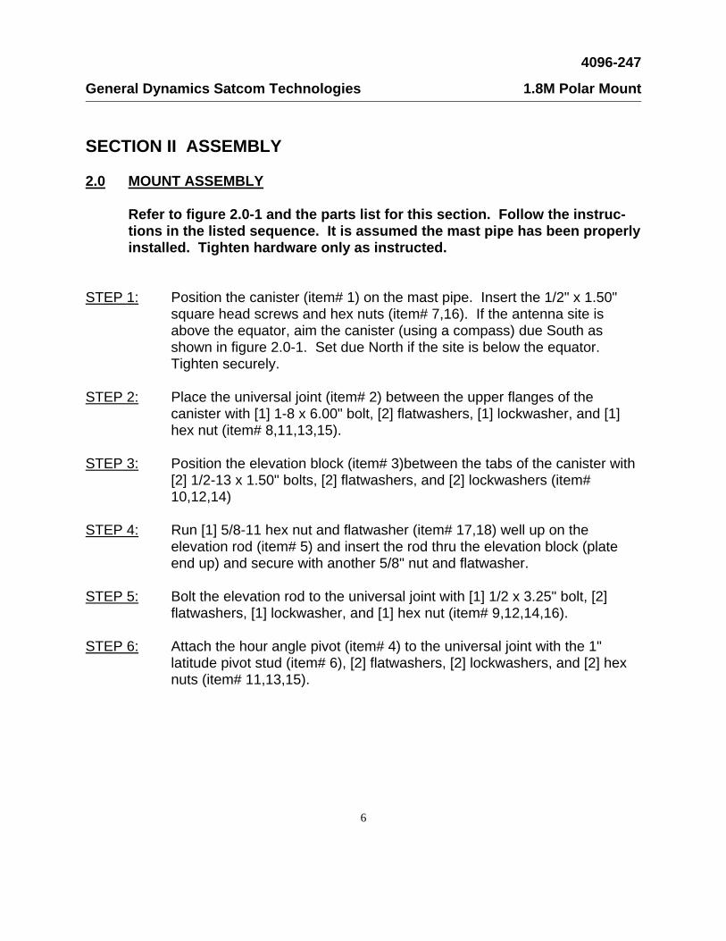
SECTION II ASSEMBLY 2.0 MOUNT ASSEMBLY Refer to figure 2.0-1 and the parts list for this section. Follow the instruc-
tions in the listed sequence. It is assumed the mast pipe has been properly installed. Tighten hardware only as instructed.
STEP 1: Position the canister (item# 1) on the mast pipe. Insert the 1/2" x 1.50"
square head screws and hex nuts (item# 7,16). If the antenna site is above the equator, aim the canister (using a compass) due South as shown in figure 2.0-1. Set due North if the site is below the equator. Tighten securely.
STEP 2: Place the universal joint (item# 2) between the upper flanges of the
canister with [1] 1-8 x 6.00" bolt, [2] flatwashers, [1] lockwasher, and [1] hex nut (item# 8,11,13,15).
STEP 3: Position the elevation block (item# 3)between the tabs of the canister with
[2] 1/2-13 x 1.50" bolts, [2] flatwashers, and [2] lockwashers (item# 10,12,14)
STEP 4: Run [1] 5/8-11 hex nut and flatwasher (item# 17,18) well up on the
elevation rod (item# 5) and insert the rod thru the elevation block (plate end up) and secure with another 5/8" nut and flatwasher.
STEP 5: Bolt the elevation rod to the universal joint with [1] 1/2 x 3.25" bolt, [2]
flatwashers, [1] lockwasher, and [1] hex nut (item# 9,12,14,16). STEP 6: Attach the hour angle pivot (item# 4) to the universal joint with the 1"
latitude pivot stud (item# 6), [2] flatwashers, [2] lockwashers, and [2] hex nuts (item# 11,13,15).

4096-247
General Dynamics Satcom Technologies 1.8M Polar Mount
7
PARTS LIST - SECTION 2.0 - MOUNT ASSEMBLY
ITEM# PART# DESCRIPTION QTY
1 0490-362 CANISTER 1
2 0490-234 UNIVERSAL JOINT 1
3 0168-085 ELEVATION BLOCK 1
4 0490-385 HOUR ANGLE PIVOT 1
5 0490-476 ELEVATION ROD 1
6 0220-039 LATITUDE PIVOT STUD 1
7 8317-002 SCREW, SHCP, 1/2-13 x 1.50" 6
8 8036-048 BOLT, 1-8 x 6.00" 1
9 8033-026 BOLT, 1/2-13 x 3.25" 1
10 8033-012 BOLT, 1/2-13 x 1.50" 2
11 8201-046 FLATWASHER, 1" 4
12 8201-043 FLATWASHER, 1/2" 4
13 8202-046 LOCKWASHER, 1" 3
14 8202-043 LOCKWASHER, 1/2" 3
15 8107-007 NUT, HEX, 1-8 3
16 8104-007 NUT, HEX, 1/2-13 7
17 8105-007 FLATWASHER, 5/8" 2
18 8201-039 NUT, HEX, 5/8-11 2

4096-247
General Dynamics Satcom Technologies 1.8M Polar Mount
8

4096-247
General Dynamics Satcom Technologies 1.8M Polar Mount
9
2.1 ACTUATOR ASSEMBLY The actuator must be ordered separately with this antenna system. All parts and
hardware installed in step 4 or 5 (except the actuator itself) come in a separate kit with the antenna system. The actuator type must be specified when ordering the antenna system to ensure the correct actuator parts kit. Refer to figures 2.1-1 thru 2.1-3 and the parts list for this section and follow the instructions in the listed sequence. Tighten hardware as instructed.
NOTE: The actuator may be mounted on either side of the mount. If your satellite
selection is predominately to the left of the antenna site location, set the actuator up in the left-hand configuration (as detailed in this manual). For satellite selec-tion predominately right of the antenna site, the actuator mount plate and actuator mount angle can be flipped over 180o to position the actuator on the left side of the mount. See figure 2.1-1 before proceeding.
STEP 1: Attach the actuator plate (item# 1) to the universal joint with [2] 1/2-13 x
1.50" bolts, [4] flatwashers, [2] lockwashers, and [2] hex nuts (item# 4,5,6,7). See figure 2.1-2. Tighten securely.
STEP 2: Attach the actuator arm (item# 2) to the hour angle pivot with [2] 1/2-13 x
1.50" bolts, [4] flatwashers, [2] lockwashers, and [2] hex nuts (item# 4,5,6,7) in the two outer holes. Run [1] 1/2" hex nut and [1] flatwasher (item# 5,7) well up onto the declination adjustment rod (item# 3) and insert the rod thru the center hole of the hour angle pivot and secure with another flatwasher and hex nut (item# 5,7) as shown in figure 2.1-2.
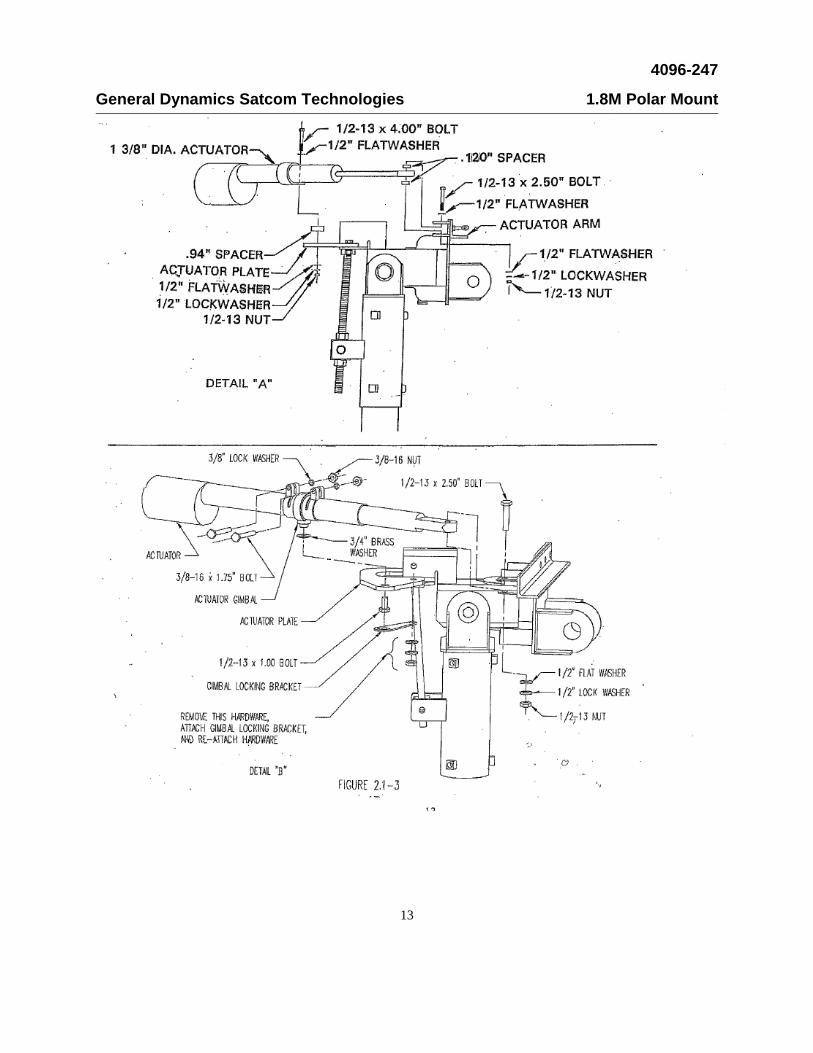
STEP 3: Check the barrel diameter of the actuator. If the diameter is 1-3/8", go to
step #4. If the barrel diameter is 2", go to step #5. STEP 4: Attach the actuator on top of the actuator plate with the .94" long spacer
between the actuator and the actuator plate, using the 1/2-13 x 4.00" bolt, [2] flatwashers, [1] lockwasher, and [1] hex nut. Mount the other end of the actuator between the [2] tabs on the actuator arm, with a .120" long spacer on each side of the actuator shaft, using [1] 1/2-13 x 2.50" bolt, [2] flatwashers, [1] lockwasher, and [1] hex nut. All hardware for mounting the actuator is supplied with the actuator kit. See figure 2.1-3, detail "A". Tighten securely.

4096-247
General Dynamics Satcom Technologies 1.8M Polar Mount
10
STEP 5: Attach the actuator gimbal on top of the actuator plate by placing [1] 3/4"
brass flatwasher onto the shoulder of the gimbal and insert it thru the actuator plate. Attach gimbal using [1] 1/2-13 X 1.00 bolt and [1] 1/2” flatwasher tighten snugly. The gimbal should be snug but must be able to pivot. Remove hardware shown in figure 2.1-3 detail B and install gimbal locking bracket as shown over the head of the 1/2-13 bolt. Reassemble using the hardware previously removed. Slide the actuator thru the gimbal and insert the [2] 3/8-16 x 2" bolts, [2] lockwashers, and [2] hex nuts to tighten the gimbal as shown. Mount the other end of the actuator between the [2] tabs on the actuator arm with [1] 1/2-13 x 2.50" bolt, [2] flatwashers, [1] lockwasher, and [1] 1/3-13 hex nut. All hardware for mounting the actuator is supplied with the actuator kit. See figure 2.1-3, detail "B". Tighten securely.
PARTS LIST - SECTION 2.1 - ACTUATOR ASSEMBLY
ITEM# PART# DESCRIPTION QTY
1 0156-623 ACTUATOR MOUNTING PLATE 1
2 0490-385 ACTUATOR MOUNTING ARM 1
3 0217-072 DECLINATION ADJUSTMENT ROD 1
4 8033-012 BOLT, 1/2-13 x 1.50" 4
5 8201-043 FLATWASHER, 1/2" 10
6 8202-043 LOCKWASHER, 1/2" 4
7 8104-007 NUT, HEX, 1/2-13 6
8 VARIES KIT, ACTUATOR 1

4096-247
General Dynamics Satcom Technologies 1.8M Polar Mount
11

4096-247
General Dynamics Satcom Technologies 1.8M Polar Mount
12
4096-247
General Dynamics Satcom Technologies 1.8M Polar Mount
13

4096-247
General Dynamics Satcom Technologies 1.8M Polar Mount
14
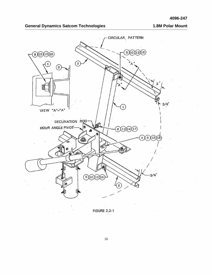
2.2 REFLECTOR ASSEMBLY Refer to figures 2.2-1 thru 2.2-2 and the parts list for this section. Follow
the instructions in the listed sequence. Tighten hardware only when in-structed.
STEP 1: Attach the reflector support tube (item# 1) to the hour angle pivot with [1]
1-8 x 6.00" bolt, [2] flatwashers, [1] lockwasher, and [1] hex nut (item# 4,9,12,15).
STEP 2: Bolt the declination adjustment rod to the reflector support with [1] 3/8-16 x
1.50", [2] flatwashers, [1] lockwasher, and [1] hex nut (item# 8,11,14,17). STEP 3: Mount the [2] reflector crossarms (item# 2) to the reflector support with the
[4] 1/2-13 x 1.75" carriage bolts, [4] flatwashers, [4] lockwashers, and [4] hex nuts (item# 5,10,13,16). Make sure the outer holes in both crossarms are oriented in a circular pattern as shown in figure 2.2-1.
STEP 4: Orient the reflector so there is a feed mounting hole at each side and one
at the bottom. Attach the reflector to the reflector support with [4] 3/8-16 x 5.00" bolts, [4] flatwashers, [4] lockwashers, and [4] hex nuts (item# 6,11,14,17) in the top four holes and [4] 3/8-16 x 4.50" bolts, [4] flatwashers, [4] lockwashers, and [4] hex nuts (item# 7,11,14,17) in the bottom four holes. See figure 2.2-2. Tighten all hardware in steps 3 & 4 securely.

4096-247
General Dynamics Satcom Technologies 1.8M Polar Mount
15
PARTS LIST - SECTION 2.2 - REFLECTOR ASSEMBLY
ITEM# PART# DESCRIPTION QTY
1 0490-357 REFLECTOR SUPPORT TUBE 1
2 0211-417 REFLECTOR CROSSARMS 2
3 VARIES REFLECTOR 1
4 8036-048 BOLT, 1-8 x 6.00" 1
5 8043-014 BOLT, CARRIAGE, 1/2-13 x 1.75" 4
6 8032-040 BOLT, 3/8-16 x 5.00" 4
7 8032-036 BOLT, 3/8-16 x 4.50" 4
8 8032-012 BOLT, 3/8-16 x 1.50" 1
9 8201-046 FLATWASHER, 1" 2
10 8201-043 FLATWASHER, 1/2" 4
11 8201-042 FLATWASHER, 3/8" 10
12 8202-046 LOCKWASHER, 1" 1
13 8201-043 LOCKWASHER, 1/2" 4
14 8202-042 LOCKWASHER, 3/8" 9
15 8107-007 NUT, HEX, 1-8 1
16 8104-007 NUT, HEX, 1/2-13 4
17 8012-007 NUT, HEX, 3/8-16 8
4096-247
General Dynamics Satcom Technologies 1.8M Polar Mount
16

4096-247
General Dynamics Satcom Technologies 1.8M Polar Mount
17
4096-247
General Dynamics Satcom Technologies 1.8M Polar Mount
18
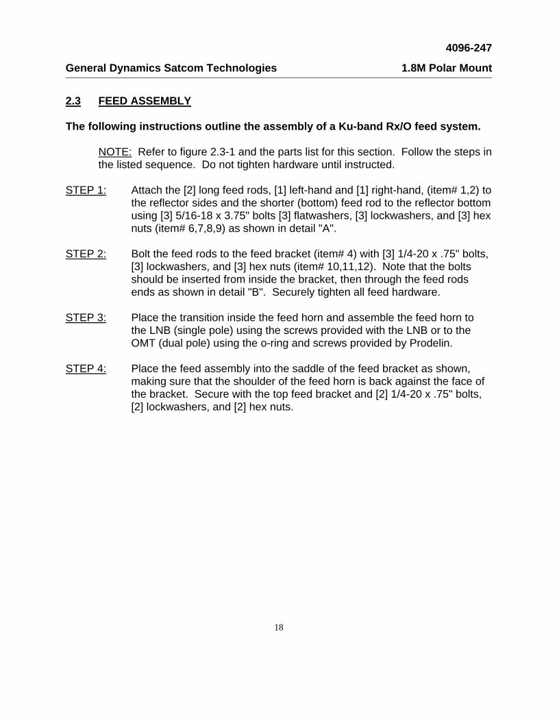
2.3 FEED ASSEMBLY The following instructions outline the assembly of a Ku-band Rx/O feed system. NOTE: Refer to figure 2.3-1 and the parts list for this section. Follow the steps in
the listed sequence. Do not tighten hardware until instructed. STEP 1: Attach the [2] long feed rods, [1] left-hand and [1] right-hand, (item# 1,2) to
the reflector sides and the shorter (bottom) feed rod to the reflector bottom using [3] 5/16-18 x 3.75" bolts [3] flatwashers, [3] lockwashers, and [3] hex nuts (item# 6,7,8,9) as shown in detail "A".
STEP 2: Bolt the feed rods to the feed bracket (item# 4) with [3] 1/4-20 x .75" bolts,
[3] lockwashers, and [3] hex nuts (item# 10,11,12). Note that the bolts should be inserted from inside the bracket, then through the feed rods ends as shown in detail "B". Securely tighten all feed hardware.
STEP 3: Place the transition inside the feed horn and assemble the feed horn to
the LNB (single pole) using the screws provided with the LNB or to the OMT (dual pole) using the o-ring and screws provided by Prodelin.
STEP 4: Place the feed assembly into the saddle of the feed bracket as shown,
making sure that the shoulder of the feed horn is back against the face of the bracket. Secure with the top feed bracket and [2] 1/4-20 x .75" bolts, [2] lockwashers, and [2] hex nuts.

4096-247
General Dynamics Satcom Technologies 1.8M Polar Mount
19
PARTS LIST - SECTION 2.3 - FEED ASSEMBLY
ITEM# PART# DESCRIPTION QTY.
1 0176-170 FEED ROD, LEFT-HAND 1
2 0176-169 FEED ROD, RIGHT-HAND 1
3 0176-171 FEED ROD, BOTTOM 1
4 0211-400 FEED BRACKET, TOP 1
5 0211-410 FEED BRACKET, BOTTOM 1
6 8031-030 BOLT, 5/16-18 x 3.75" 3
7 8201-041 FLATWASHER, 5/16" 3
8 8202-041 LOCKWASHER, 5/16" 3
9 8101-009 NUT, HEX, 5/16-18 3
10 8030-006 BOLT, 1/4-20 x .75" 5
11 8202-040 LOCKWASHER, 1/4" 5
12 8100-007 NUT, HEX, 1/4-20 5
13 0183-299 FEED HORN 1

4096-247
General Dynamics Satcom Technologies 1.8M Polar Mount
20

4096-247
General Dynamics Satcom Technologies 1.8M Polar Mount
21
3.0 SATELLITE ALIGNMENT This section covers two steps in the alignment procedures: A: Pre-alignment and B:
Alignment to Satellite Orbital Arc. Refer to figures 3.0-1 thru 3.0-3 and follow the instructions in the listed sequence.
A: PRE-ALIGNMENT Two basic adjustments are to be made before aligning the antenna with the satellite arc:
Latitude and Declination. These adjustments are simple to make, yet they are critical for proper tracking of the arc.
LATITUDE ADJUSTMENT: The latitude angle adjustment provides proper elevation
of the antenna system in relation to the site latitude. Adjustments are made by elevating the antenna and setting the elevation adjustment assembly to the appropriate angle for reception at that site's latitude.
DECLINATION ADJUSTMENT: The declination angle adjustment allows the
antenna to track the entire satellite arc. This angle is a function of the site's latitude. The declination angle is set by adjusting the nuts on the declination rod. The angle is measured by placing an inclinometer on the reflector support tube. The measured angle will be the sum of the declination angle and the 22.3 offset angle of the reflector.
STEP 1: Determine the antenna site's latitude. The site latitude may be obtained by
contacting a local airport or by referring to a map listing latitudes. STEP 2: Determine the antenna site declination angle from the Declination Chart (page
23) and add 22.3 (the reflector offset angle). This is referred to as the declination-offset angle. Example: For Hickory, N.C.
REFLECTOR OFFSET ANGLE ------- 22.3 DECLINATION ANGLE (HICKORY)--- 5.7 TOTAL DECLINATION-OFFSET ----- 28.0 STEP 3: Position the reflector to look straight ahead (horizontally), by extending the
actuator. See figure 3.0-1. STEP 4: Position the inclinometer on the hour angle pivot (position "A") and set to 0, as
indicated in figure 3.0-2, by turning the 3/4" nuts located at the elevation adjustment block. Hand tighten. Recheck the inclinometer indication and re-adjust if required.

4096-247
General Dynamics Satcom Technologies 1.8M Polar Mount
22
STEP 5: Position the inclinometer on the reflector support tube (position "B") and set to
the declination-offset angle (from step# 2) by adjusting the 3/8" nuts on the declination adjustment rod. See figure 3.0-2.
STEP 6: After correct declination-offset angle is indicated on the inclinometer, tighten the
adjustment nuts against the actuator arm. Recheck the inclinometer indication and re-adjust if required.
STEP 7: Place the inclinometer back on the hour angle pivot plate (position "A") and set to
the latitude angle (from step# 1) by turning the 3/4" nuts located at the elevation adjustment block.
STEP 8: After correct latitude angle is indicated on the inclinometer, tighten the
adjustment nuts against the elevation adjustment block. Recheck the inclinome-ter indication and readjust if required.
STEP 6: Securely tighten latitude pivot stud, elevation adjustment block, and clevis end of
elevation adjustment rod hardware. B: ALIGNMENT TO SATELLITE ORBITAL ARC After adjusting the latitude and
declination-offset angles, the antenna can be aligned with a selected satellite. This alignment procedure requires driving (raising or lowering via the actuator) the antenna to a chosen satellite elevation, then rotating the entire antenna assembly to the required satellite bearing (compass heading). The satellite selected is easily found with this procedure. Peak the signal by making slight antenna compass heading adjustments.
STEP 1: Complete all wiring connections to the satellite receiver, antenna positioner, and
monitor according to instructions in the respective manuals, and then apply AC power to the system.
STEP 2: Place the inclinometer on the bottom rib of the reflector as shown in figure 3.0-2.
STEP 3: Set elevation for the target satellite by moving the antenna with the actuator until
the inclinometer reading coincides with the chosen satellite's elevation. It may be necessary to loosen the actuator gimbal and "slip" the actuator barrel within the gimbal to obtain the elevation angle. If so, position such that the actuator does not fully extend or fully retract into the mechanical limits before the elevation angle is reached. Refer to the instructions with your actuator for additional information.

4096-247
General Dynamics Satcom Technologies 1.8M Polar Mount
23
STEP 4: Loosen the 1/2" canister bolts, then uniformly tighten to hold canister centered on
the mast but still allow rotation about the mast. STEP 5: Rotate the antenna until the satellite compass heading is reached, using the
compass heading coordinate as read from a compass as a reference. Note: when using the compass, stand several feet behind the antenna to prevent magnetic deviation (of the compass) caused by the metals in the mount.
STEP 6: Peak the signal by slightly rotating the antenna, After the signal is peaked,
securely and uniformly tighten the 1/2" canister bolts. STEP 7: Drive the antenna through the satellite arc and observe the picture quality. The
quality should be excellent on all satellites. If not, re-check the reflector compass heading and adjust if necessary. Figure 3.0-3 illustrates some common tracking problems.
DECLINATION CHART
LATITUDE DECLINATION LATITUDE DECLINATION
0 0 47.5 6.4
10 1.5 50 6.6
20 3 52.5 6.9
22.5 3.3 55 7.1
25 3.7 57.5 7.3
27.5 4 60 7.5
30 4.7 62.5 7.6
32 4.7 65 7.8
35 5 67.5 8
37.5 5.3 70 8.1
40 5.6 80 8.4
42.5 5.9 90 8.6
45 6.1

4096-247
General Dynamics Satcom Technologies 1.8M Polar Mount
24

4096-247
General Dynamics Satcom Technologies 1.8M Polar Mount
25

4096-247
General Dynamics Satcom Technologies 1.8M Polar Mount
26
4.0 MAINTENANCE OVERVIEW After installation, the antenna requires only periodic inspection. It is anticipated
that maintenance, if required, will be minimal and easily handled by a local or in-house maintenance staff. The materials used in the construction of this Earth Station Antenna virtually eliminate any maintenance repairs.
4.1 PERIODIC INSPECTION It is suggested that a periodic inspection be performed at least every six months. NOTE: After any severe weather conditions, inspection of the antenna should be
performed to determine if foreign objects have caused damage or if survival specifications have been exceeded.
This inspection should include the following: STEP 1: Check all bolting locations - all bolts should be tight. STEP 2: Check all structural members - repair or replace if damaged. STEP 3: Check the foundation anchor bolts - they must be secure and no
failure signs in foundation. STEP 4: Check for corrosion - on the reflector structure and the mount. 4.2 REFLECTOR Prodelin's reflector does not require any maintenance. The composite
construction of the reflector is virtually impervious to any damages that could be caused by weather or atmospheric conditions.
It is only necessary to inspect for any physical damage done by vandalism or
very severe weather conditions. Should any damage be detected to a portion of the reflector, contact the
Customer Service Department at General Dynamics for recommendations involving reflector repair.

4096-247
General Dynamics Satcom Technologies 1.8M Polar Mount
27
4.3 MOUNT AND REFLECTOR SUPPORT STRUCTURE The mount and reflector support structure supplied with this antenna is of steel
construction and has a hot-dip galvanized finish. If inspection shows any signs of structural failure, the mount members that are
damaged should be repaired or replaced. CORROSION: Any corrosion on steel members may be repaired with a cold,
zinc-rich galvanizing paint. 4.4 FEED AND FEED SUPPORT The feed support should be inspected to insure that all hardware is secure. The
feed/radio mounting bolts should be tight. The feed horn window should be inspected to insure that it is intact so that no
moisture can collect inside the feed horn. Replace if damaged.