18-HD39D1-4 08/01/2010 Installation Guide - Schlage Link
32
18-HD39D1-4 Thermostat Installation Instructions Models TZEMT400AB32MAA TZEMT500AB32MAA P516-275 The TZEMT400 and TZEMT500 Thermostats are compatible with single and multistage forced air systems, including: • Gas furnace systems • Oil furnace systems • Electric furnace systems • Heat pump systems • Air conditioning systems The TZEMT400 and TZEMT500 Thermostats may be compatible with some other system types, including: • Boiler systems • Geothermal systems • Multi-zoned systems The TZEMT400 and TZEMT500 Thermostats are not compatible with the following system types: • Radiant floor systems • Wall heating systems • Proprietary HVAC Communication Protocols Î Î The TZEMT400 and TZEMT500 Thermostats are not compatible with dual fuel systems (gas or oil furnace & heat pump combined) without adding a dual fuel accessory relay kit. These thermostats do not have an emergency heat relay when applied with a dual fuel relay kit. Î Î NOTE: A 24 Volt common and hot wire MUST be connected to the TZEMT400 or TZEMT500 for operation. Use this guide and the “Thermostat Starter Kit Quick Start Guide” for installation. The information contained in document P516-000, “Thermostat Model TZEMT043AZ32MAA”, does not apply to this kit. Schlage LiNK™ Customer Service: (877) 288-7707 Contents Physical Installation and Wiring ....................................................................................................................................... 2 Field Wiring Diagrams - TZEMT500 ................................................................................................................................. 6 Field Wiring Diagrams - TZEMT400 ................................................................................................................................. 9 Optional Remote Temperature Sensors Installation - TZEMT500 Only ......................................................................... 10 System Settings at Thermostat ...................................................................................................................................... 12 Perform System Checkout ............................................................................................................................................. 14 Enroll Thermostat into Schlage LiNK™ System............................................................................................................. 15 Product Specifications ................................................................................................................................................... 16 Operation ....................................................................................................................................................................... 17 Menu Maps .................................................................................................................................................................... 19 User Settings ................................................................................................................................................................. 20 Installer Settings ............................................................................................................................................................ 25 Schedules ...................................................................................................................................................................... 28 LED Reference............................................................................................................................................................... 30 Warranty......................................................................................................................................................................... 31
Transcript of 18-HD39D1-4 08/01/2010 Installation Guide - Schlage Link

18-HD39D1-4
ThermostatInstallation InstructionsModels TZEMT400AB32MAA TZEMT500AB32MAA
P516-275
The TZEMT400 and TZEMT500 Thermostats are compatible with single and multistage forced air systems, including:
• Gas furnace systems
• Oil furnace systems
• Electric furnace systems
• Heat pump systems
• Air conditioning systems
The TZEMT400 and TZEMT500 Thermostats may be compatible with some other system types, including:
• Boiler systems
• Geothermal systems
• Multi-zoned systems
The TZEMT400 and TZEMT500 Thermostats are not compatible with the following system types:
• Radiant floor systems
• Wall heating systems
• Proprietary HVAC Communication Protocols
ÎÎ The TZEMT400 and TZEMT500 Thermostats are not compatible with dual fuel systems (gas or oil furnace & heat pump combined) without adding a dual fuel accessory relay kit. These thermostats do not have an emergency heat relay when applied with a dual fuel relay kit.
ÎÎ NOTE: A 24 Volt common and hot wire MUST be connected to the TZEMT400 or TZEMT500 for operation.
Use this guide and the “Thermostat Starter Kit Quick Start Guide” for installation. The information contained in document P516-000, “Thermostat Model TZEMT043AZ32MAA”, does not apply to this kit.
Schlage LiNK™ Customer Service:
(877) 288-7707
ContentsPhysical Installation and Wiring .......................................................................................................................................2Field Wiring Diagrams - TZEMT500 .................................................................................................................................6Field Wiring Diagrams - TZEMT400 .................................................................................................................................9Optional Remote Temperature Sensors Installation - TZEMT500 Only .........................................................................10System Settings at Thermostat ......................................................................................................................................12Perform System Checkout .............................................................................................................................................14Enroll Thermostat into Schlage LiNK™ System .............................................................................................................15Product Specifications ...................................................................................................................................................16Operation .......................................................................................................................................................................17Menu Maps ....................................................................................................................................................................19User Settings .................................................................................................................................................................20Installer Settings ............................................................................................................................................................25Schedules ......................................................................................................................................................................28LED Reference ...............................................................................................................................................................30Warranty .........................................................................................................................................................................31

2
3 Identify the existing HVAC System Type from the list below.
Indoor Unit Type System Type
� Gas Furnace � Single Stage Gas Furnace
� 1 Stage Cooling
� Multi Stage Gas Furnace
� 1 Stage Cooling
� 2 Stage Cooling
� Electric Furnace or Air Handler
� Single Stage PSC Blower, Electric Furnace or Air Handler
� 1 Stage Cooling
� 1 Stage Heat Pump
� Multi Stage, Variable Speed Blower, Electric Furnace or Air Handler
� 1 Stage Cooling
� 1 Stage Heat Pump
� 2 Stage Cooling
� 2 Stage Heat Pump
CAUTION: EQUIPMENT DAMAGE HAZARD - Improper system type selection can lead to equipment damage or high utility costs. Use the System Type list to properly select and setup the control to ensure proper heating and cooling system operation.
4 Determine if your system has a 24 VAC common wire which is required to power the thermostat.a. If your existing thermostat has a terminal labeled C, X, B, or COM with a wire connected to it, skip to step 6.b. If your thermostat does not have a C, X, B, or COM terminal, or does not have a wire connected to it, go to step 5.
2 Remove the existing thermostat cover from the wall plate. Leave wires attached.Consult instructions that came with existing thermostat as needed.
MERCURY NOTICEWhen this control is replacing an old control that contains mercury in a sealed tube, do not dispose of your old control in the trash. Dispose of properly. Contact your local waste management authority for instructions regarding recycling and proper disposal of the old control.
A listing of heating, ventilating and air conditioning wholesalers that participate in the Thermostat Recycling Corporation’s recycling program are available at www.thermostat-recyle.org.
Wall plateThermostat cover
The look of the existing thermostat may vary
1 WARNINGVoltage hazard. Can cause electrical shock or equipment damage. Disconnect power to heating and cooling equipment before beginning installation.
Physical Installation and Wiring

3
5 Connect a 24 VAC common wire to power the thermostat.a. Locate all unused wires from the thermostat wire bundle
and write down the colors.• 24V Common wire is typically (not always) colored blue
Unused wires
Thermostatwire bundle
b. Go to the indoor air handler or furnace and remove the cover(s) to access the 24 VAC air handler or furnace wire terminals.
24 VACAir handleror Furnace
wireterminals
Air handleror Furnace
cover
c. Find the 24 VAC common terminal identified with the letter C, X, B, or COM.• This terminal may already have a wire connected to
it but it may not be a wire that is connected to the thermostat
24 VAC commonterminal
(C, X, B, or COM)
G
W
R
C
d. Locate the thermostat wire bundle inside the air handler or furnace panel.• This wire bundle is routed from the thermostat, through
the walls, and into the air handler or furnace panel.
• This bundle can be identified at the air handler or furnace by checking the wire colors connected and not connected and comparing to the wire bundle at the thermostat.
Thermostatwire bundle
G
W
R
C
Unused wires
e. Find a wire from the thermostat bundle that is unused at the thermostat and at the air handler or furnace. • It is possible that one of the unused wires at the
thermostat will already be connected to the 24 VAC common terminal at the air handler or furnace. If so, go to step 6.
G
W
R
C Unused wire
f. Connect the unused wire to the 24 VAC terminal, then replace the air handler or furnace cover.• The 24 VAC common wire is typically (but not
always) blue in color. If the blue wire is not used, it is recommended that you use the blue wire.
G
W
R
CConnect
wire

4
6 Review the wiring chart information.a. Refer to:
• Chart 1 - If you do NOT have a heat pump
• Chart 2 - If you have a heat pump
b. Select the correct row based upon the thermostat being replaced, and then circle the wire labels you have.c. Connect your wires as shown in the New Thermostat Terminals row.
Chart 1: Gas or Electric
(Single Stage or Multistage)
Themostat Being Replaced Wire Labels
All Brands C
X
B
R
RC
RH W
W1
W2 G
F
Y
Y1
Y2
Connects to
New Thermostat Terminals 24COM 24RC 24RH W1 W2/O/B G Y1 Y2
Chart 2: Heat Pump
(Single Stage or Multistage)
Themostat Being Replaced Wire Labels
Trane/American Standard (Weathertron) or York
COM
C
B
R
RC
RH E
X2
W
W1
W2
Y
AUX
O G Y
Y1
Y2
Other Brands COM
C
X
R
RC
RH E
X2
W
W1
W2
Y
AUX
O
B
G
F
Y
Y1
Y2
Lennox C
X
R
RC
**VR
**V
RH E
X2
W
W1
W2
Y
AUX
O
**R
G
F
Y
Y1
Y2
Connects to
New Thermostat Terminals 24COM 24RC 24RH *W1 W2/O/B G Y1 Y2
* Connect two wires to the W1 terminal
** If your existing thermostat has a “V” or “VR” wire label, connect that wire to “24RC” on the new thermostat, then connect the wire labeled “R” to “W2/O/B” on the new thermostat
Some wire terminals may not be used
Some wire terminals may not be used

5
7 Remove existing wall plate.ÎÎ Note: During this process, make sure that the wires do not pull back into wall
opening.
a. Detach all wires from wall plate.b. Remove all screws attaching the wall plate to the wall and remove wall plate.
ÎÎ See MercuryÎNotice on page 2.
Wall plate
8 Separate the face of the new thermostat from the wall plate.Apply pressure at two tabs on top of wall plate to release it.
ÎÎ NOTE: It is not recommended that this Z-waveTM thermostat be mounted onto metal structures. Metal may adversely affect the radio frequency (RF) communication between the thermostat and the Z-waveTM bridge.
24C24RC24RHW1G
Y1
RS1RS1RS2RS2
W2/0/BY2
Wall plate
Tabs
9 Mark two mounting holes using new wall plate.a. Pull wires through hole in center of wall plate.b. Locate the new wall plate over existing opening.c. Mark two holes with pencil.d. Use a level to verify that the two hole locations are level. e. Correct hole locations as needed.
24C24RC24RHW1G
Y1
RS1RS1RS2RS2
W2/0/BY2
10 Prepare two mounting holes.a. Drill 1/16” pilot holes in the two locations that were marked in step 9. If mounting to
drywall with no studs behind it, enlarge pilot holes to 1/8” for anchors (included with the thermostat).
b. If using anchors, screw them into the holes.
Anchors

6
12 Attach all wires securely to the new thermostat.(See the Field Wiring Diagrams on the following page.)Note: A wire must be connected to “24COM” to power the thermostat. a. Use the information from step 6 to match the wires to the correct terminals.b. Use 1/8” blade screwdriver to secure wires in terminals.
CAUTION: EQUIPMENT DAMAGE HAZARD Improper wiring can lead to equipment damage. Follow the Terminal Connection information from step 6 carefully to ensure the control is wired properly. After wires are secure, bare wires MUST NOT touch each other. See the Field Connection Wiring Diagrams on the following pages for specific system applications.
24C24RC24RHW1
W2/0G
Y1Y2
RS1RS1RS2RS2
Field Wiring Diagrams - TZEMT500
11 Install new wall plate.a. Pull wires through hole in center of wall plate.b. Locate the new wall plate over existing opening.c. Attach wall plate to wall using two screws provided. Do not overtighten.
24C24RC24RHW1G
Y1
RS1RS1RS2RS2
W2/0/BY2
The following table can be used to find the correct field connection wiring diagram for the HVAC System Type that is being installed.
Indoor Unit Outdoor Unit
1 Stage Cooling
2 Stage Cooling
2 Step Cooling
1 Stage Heat Pump
2 Stage Heat Pump
2 Step Heat Pump
1 or 2 Stage Gas Furnace (PSC/CTM) A NA NA NA NA NA
2 Stage VSPD Gas Furnace A A B NA NA NA
COM Furnace A A A NA NA NA
Air Handler (PSC/CTM) A NA NA C NA NA
VSPD Air Handler A A B C C D
COM Air Handler A A A C C C
Oil Furnace (PSC) E NA NA NA NA NA
VSPD Oil Furnace E E F NA NA NA

7
W1 HEAT
JP1: internal RC/RH Jumper
24RC
24RH
G FAN
W2/O/BY1 COMP
Y2 COMP
24C
Gas Furnace or Air Handler
System Type A - 1 or 2 Stage Heating with 1 or 2 Stage Cooling
Fan G
Heat Stage 1 W1
Compressor Stage 1 Y1
24VAC Return R
24VAC Common B/C
Compressor Stage 2 Y2
BK
Heat Stage 2 W2
RED
GREEN
WHITE
YELLOW
ORANGE
BROWN
BLUE
RS1
RS1
RS2
RS2
Remote Sensors
RemoteSensor 1
RemoteSensor 2
Wiring is not polarized
Remote Temperature Sensor Connections and Operation: (Note 7)Indoor sensor connected to RS1. Replaces internal sensor. RS2 not connected.Indoor sensor connected to RS2. Averages temperature with internal sensor. RS1 not connected.Indoor sensors connected to RS1 and RS2. Averages RS1 and RS2 sensor temperatures. Internal sensor is not used.Outdoor sensor connected to RS2. Reports outdoor temperature to comfort control.Indoor sensor connected to RS1 and outdoor sensor connected to RS2. RS1 replaces the internal sensor. RS2 reports the outdoor temperature to comfort control.
Note 1 - May be W or W1
(Note 1)
(Note 5)
(Note 2)
(Note 3, Note 4)
Note 2 - May be Y, Y1, or YLO
Note 3 - May be Y or Y2
Note 5 - R required for 2 stage cooling unitNote 6 - For 2 Stage Cooling, outdoor unit contains two compressorsNote 7 - The remote sensor feature is available only on the TZEMT500
Note 4 - Y2 only found on variable speed furnace or air handler
Thermostat Connection (Note 6)
(Note 7)
Outdoor Unit
Compressor Stage 1 Y1
24VAC Return R
24VAC Common B
Compressor Stage 2 Y2
W1 HEAT
JP1: internal RC/RH Jumper
24RC
24RH
G FAN
W2/O/BY1 COMPY2 COMP
24C
Gas Furnace or Air Handler
System Type B - 2 Stage Variable Speed Gas Furnace or Variable Speed Air Handler with 2 Step Cooling
Fan G
Heat Stage 1 W1
24VAC Return R
24VAC Common B/C
Compressor Stage 1 Y
Compressor Stage 2 BK
Heat Stage 2 W2
RED
GREEN
WHITE
YELLOW
ORANGEBROWN
BLUE
RS1
RS1
RS2
RS2
Remote Sensors(Note 5)
RemoteSensor 1
RemoteSensor 2
Air Handler
Jumper
Furnace
Wiring is not polarized
Note 1 - Field installed jumper from R to O.
(Note 1)(Note 2)
Note 2 - Cut/remove R to BK jumperNote 3 - For non-communicating variable speed air handler. (For communicating air handler, use system type A diagram.)
Thermostat Connection
O
(Note 3, Note 4)
Jumper
Note 4 - For 2 Step Cooling, outdoor unit contains one 2 stage scroll compressorNote 5 - The remote sensor feature is available only on the TZEMT500
(Note 2)
(Note 2)
YLO
Outdoor Unit
Compressor Stage 1 Y1
24VAC Return R
24VAC Common B
Compressor Stage 2 Y2
Remote Temperature Sensor Connections and Operation: (Note 5)Indoor sensor connected to RS1. Replaces internal sensor. RS2 not connected.Indoor sensor connected to RS2. Averages temperature with internal sensor. RS1 not connected.Indoor sensors connected to RS1 and RS2. Averages RS1 and RS2 sensor temperatures. Internal sensor is not used.Outdoor sensor connected to RS2. Reports outdoor temperature to comfort control.Indoor sensor connected to RS1 and outdoor sensor connected to RS2. RS1 replaces the internal sensor. RS2 reports the outdoor temperature to comfort control.
W1 HEAT
JP1: internal RC/RH Jumper
24RC
24RH
G FAN
W2/O/BY1 COMP
Y2 COMP
24C
Air Handler
System Type C - PSC, Variable Speed, or Communicating Air Handler with 1 or 2 Stage/Step Heat Pump
Fan G
Heat Stage 1 W1
Compressor Stage 1 Y1
24VAC Return R
24VAC Common B/C
Compressor Stage 2 Y2
BK
O
RED
GREEN
WHITE
YELLOW
ORANGE
BROWN
BLUE
RS1
RS1
RS2
RS2
Remote Sensors(Note 8)
RemoteSensor 1
RemoteSensor 2
Wiring is not polarized
Note 1 - May be W or W1
(Note 1)
(Note 2)
(Note 3)
(Note 4, Note 5, Note 6, Note 7)
Note 2 - May be Y, Y1, or YLO
Note 3 - May be Y or Y2Note 4 - Applies to 2 step heat pumps matched with communicating air handler only. All other variable speed air handlers use system type D diagram.
Thermostat Connection
Remote Temperature Sensor Connections and Operation: (Note 8)Indoor sensor connected to RS1. Replaces internal sensor. RS2 not connected.Indoor sensor connected to RS2. Averages temperature with internal sensor. RS1 not connected.Indoor sensors connected to RS1 and RS2. Averages RS1 and RS2 sensor temperatures. Internal sensor is not used.Outdoor sensor connected to RS2. Reports outdoor temperature to comfort control.Indoor sensor connected to RS1 and outdoor sensor connected to RS2. RS1 replaces the internal sensor. RS2 reports the outdoor temperature to comfort control.
Outdoor Unit
Compressor Stage 1 Y1
24VAC Return R
24VAC Common B
Compressor Stage 2 Y2
X2
O
Note 5 - For 2 Stage Cooling, outdoor unit contains two compressorsNote 6 - For 2 Step Cooling, outdoor unit contains one 2 stage scroll compressorNote 7 - PSC air handler for single stage heat pump onlyNote 8 - The remote sensor feature is available only on the TZEMT500
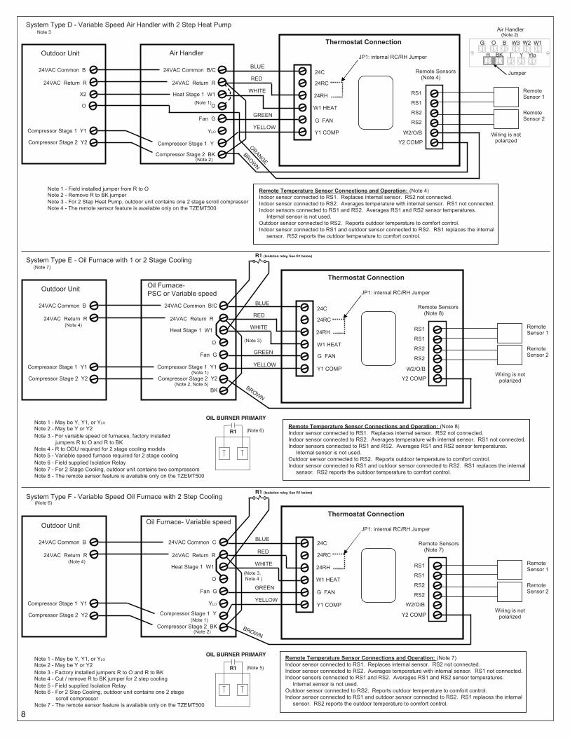
8
W1 HEAT
JP1: internal RC/RH Jumper
24RC
24RH
G FAN
W2/O/BY1 COMP
Y2 COMP
24C
Air Handler
System Type D - Variable Speed Air Handler with 2 Step Heat Pump
Fan G
Heat Stage 1 W1
Compressor Stage 1 Y
24VAC Return R
24VAC Common B/C
Compressor Stage 2 BK
O
RED
GREEN
WHITE
YELLOW
ORANGE
BROWN
BLUE
RS1
RS1
RS2
RS2
Remote Sensors(Note 4)
RemoteSensor 1
RemoteSensor 2
Wiring is not polarized
Note 1 - Field installed jumper from R to O
(Note 1)
Note 2 - Remove R to BK jumper
Thermostat Connection Note 3
YLO
Remote Temperature Sensor Connections and Operation: (Note 4)Indoor sensor connected to RS1. Replaces internal sensor. RS2 not connected.Indoor sensor connected to RS2. Averages temperature with internal sensor. RS1 not connected.Indoor sensors connected to RS1 and RS2. Averages RS1 and RS2 sensor temperatures. Internal sensor is not used.Outdoor sensor connected to RS2. Reports outdoor temperature to comfort control.Indoor sensor connected to RS1 and outdoor sensor connected to RS2. RS1 replaces the internal sensor. RS2 reports the outdoor temperature to comfort control.
Outdoor Unit
Compressor Stage 1 Y1
24VAC Return R
24VAC Common B
Compressor Stage 2 Y2
X2
O
(Note 2)
Note 3 - For 2 Step Heat Pump, outdoor unit contains one 2 stage scroll compressorNote 4 - The remote sensor feature is available only on the TZEMT500
Air Handler
Jumper
(Note 2)
W1 HEAT
JP1: internal RC/RH Jumper
24RC
24RH
G FAN
W2/O/BY1 COMP
Y2 COMP
24C
Oil Furnace- PSC or Variable speed
System Type E - Oil Furnace with 1 or 2 Stage Cooling
Fan G
Heat Stage 1 W1
Compressor Stage 1 Y1
24VAC Return R
24VAC Common B/C
Compressor Stage 2 Y2
BK
RED
GREEN
WHITE
YELLOW
BROWN
BLUE
RS1
RS1
RS2
RS2
Remote Sensors(Note 8)
RemoteSensor 1
RemoteSensor 2
Wiring is not polarized
Note 1 - May be Y, Y1, or YLO
(Note 1)
(Note 6)Note 2 - May be Y or Y2Note 3 - For variable speed oil furnaces, factory installed jumpers R to O and R to BKNote 4 - R to ODU required for 2 stage cooling modelsNote 5 - Variable speed furnace required for 2 stage coolingNote 6 - Field supplied Isolation Relay
Thermostat Connection
O
Remote Temperature Sensor Connections and Operation: (Note 8)Indoor sensor connected to RS1. Replaces internal sensor. RS2 not connected.Indoor sensor connected to RS2. Averages temperature with internal sensor. RS1 not connected.Indoor sensors connected to RS1 and RS2. Averages RS1 and RS2 sensor temperatures. Internal sensor is not used.Outdoor sensor connected to RS2. Reports outdoor temperature to comfort control.Indoor sensor connected to RS1 and outdoor sensor connected to RS2. RS1 replaces the internal sensor. RS2 reports the outdoor temperature to comfort control.
Outdoor Unit
Compressor Stage 1 Y1
24VAC Return R
24VAC Common B
Compressor Stage 2 Y2
(Note 4)
(Note 7)
(Note 2, Note 5)
(Note 3)
R1
OIL BURNER PRIMARY
R1 (Isolation relay, See R1 below)
Note 7 - For 2 Stage Cooling, outdoor unit contains two compressorsNote 8 - The remote sensor feature is available only on the TZEMT500
W1 HEAT
JP1: internal RC/RH Jumper
24RC
24RH
G FAN
W2/O/BY1 COMP
Y2 COMP
24C
Oil Furnace- Variable speed
System Type F - Variable Speed Oil Furnace with 2 Step Cooling
Fan G
Heat Stage 1 W1
24VAC Return R
24VAC Common C
RED
GREEN
WHITE
YELLOW
BROWN
BLUE
RS1
RS1
RS2
RS2
Remote Sensors(Note 7)
RemoteSensor 1
RemoteSensor 2
Wiring is not polarized
Note 1 - May be Y, Y1, or YLO
(Note 1)
Note 2 - May be Y or Y2Note 3 - Factory installed jumpers R to O and R to BKNote 4 - Cut / remove R to BK jumper for 2 step cooling
Thermostat Connection
O
(Note 5)
Note 5 - Field supplied Isolation Relay
R1 (Isolation relay, See R1 below)
Compressor Stage 1 Y
Compressor Stage 2 BK
YLO
Outdoor Unit
Compressor Stage 1 Y1
24VAC Return R
24VAC Common B
Compressor Stage 2 Y2
(Note 4)
(Note 6)
(Note 2)
(Note 3, Note 4 )
R1
OIL BURNER PRIMARY
Note 6 - For 2 Step Cooling, outdoor unit contains one 2 stage scroll compressorNote 7 - The remote sensor feature is available only on the TZEMT500
Remote Temperature Sensor Connections and Operation: (Note 7)Indoor sensor connected to RS1. Replaces internal sensor. RS2 not connected.Indoor sensor connected to RS2. Averages temperature with internal sensor. RS1 not connected.Indoor sensors connected to RS1 and RS2. Averages RS1 and RS2 sensor temperatures. Internal sensor is not used.Outdoor sensor connected to RS2. Reports outdoor temperature to comfort control.Indoor sensor connected to RS1 and outdoor sensor connected to RS2. RS1 replaces the internal sensor. RS2 reports the outdoor temperature to comfort control.

9
IMPORTANT: Use the TZEMT500 field wiring diagrams as a guide when making field wiring connections to the TZEMT400.
ÎÎ NOTE: The TZEMT500 terminal block configuration differs from the TZEMT400 terminal block. The TZEMT500 has two terminal blocks with 12 terminals and the TZEMT400 has one terminal block with 8 terminals.
See the table below for a comparison of the terminal names. Functionality is the same for the matching terminals.
Terminal Labels
TZEMT500 TZEMT400
24C C 24V
24RC RC 24V
24RH RH 24V
W1 W1
G G
Y1 Y1
RS1 n/a
RS1 n/a
RS2 n/a
RS2 n/a
W2/O/B W2/O/B
Y2 Y2
24C24RC24RHW1GY1
RS1RS1RS2RS2
W2/O/BY2
TZEMT500 wall plate
RH 24VW1W2/O/BGY1Y2
Run Wires Here
No wires inshaded areas
C 24VRC 24V
TZEMT400 wall plate
Field Wiring Diagrams - TZEMT400

10
Wire specification (RS1 & RS2): 2 conductors, 18 gauge wire. Make sure that the sensor wires have a cable separate from the thermostat cable. Best results for distances of 100 feet or less. Accuracy may be affected for distances up to a maximum of 200 feet. Shielded cable is recommended for distances over 100 feet and less than 200 feet.
CAUTION: Keep this wiring at least one foot away from large inductive loads such as electronic air cleaners, motors, line starters, lightning ballasts, and large distribution panels. Failure to follow these wiring practices may introduce electrical interference (noise) which can cause erratic system operation. Shielded cable is required if the above wiring guidelines cannot be met. Be sure to ground only one end of the shield to the thermostat common terminal. Tape back the other end of the shield.
Remote Sensors Part NumbersRemote Indoor Sensor: Use ZZSENSAL0400AA for indoor applications.
Remote Outdoor Sensor: Use BAYSEN01ATEMPA for outdoor applications.
ÎÎ IMPORTANT: Make sure that the sensor wires have a cable separate from the thermostat cable.
ÎÎ IMPORTANT: Follow directions below for averaging. These instructions replace the averaging information found in the Installer’s Guide for the ZZSENSAL0400AA.
ÎÎ Note: Remote Sensor 2 can be selected as an indoor sensor or an outdoor sensor.
Remote Temperature Sensor Connections and Operation:A) Indoor sensor connected to RS1. Replaces internal sensor. RS2 not connected.
Remote Sensor 1 (RS1) replaces the internal temperature sensor of the thermostat. This allows the thermostat to be installed in a location different than the area where the temperature will be measured. Use ZZSENSAL0400AA. See Figure A.
B) Indoor sensor connected to RS2. Averages temperature with internal sensor. RS1 not connected.RS2 is used as an indoor temperature sensor that averages temperatures with the internal sensor. Use ZZSENSAL0400AA. See Figure B.
If RS2 is set to indoor location (“IN” - Default selection in the thermostat installation set up menu) and a sensor is attached to the RS2 sensor terminals of the thermostat, the RS2 temperature is averaged with the thermostats internal temperature sensor.
C) Indoor sensors connected to RS1 and RS2. Averages RS1 and RS2 sensor temperatures. Internal sensor is not used.Remote Sensor 1 (RS1) and Remote Sensor 2 (RS2) are both used as indoor sensors. The RS1 temperature and RS2 temperature is averaged. See Figure C.
D) Outdoor sensor connected to RS2. Reports outdoor temperature to comfort control.RS2 is used as an outdoor temperature sensor. Use BAYSEN01ATEMPA. See Figure B.
If RS2 is set to outdoor location (“OUT” in the thermostat installation set up menu) and a sensor is attached to the RS2 sensor terminals of the thermostat, the RS2 temperature is used to report outdoor temperature. It is also displayed on the thermostat main screen. See Step 19 to configure for outdoor temperature sensing.
E) Indoor sensor connected to RS1 and Outdoor sensor connected to RS2. RS1 replaces the internal sensor. RS2 reads the outdoor temperature.Remote Sensor 1 (RS1) replaces the internal temperature sensor of the thermostat. This allows the thermostat to be installed in a location different than the area where the temperature will be measured. Use ZZSENSAL0400AA.
RS2 is used as an outdoor temperature sensor. Use BAYSEN01ATEMPA. See Figure C.
If RS2 is set to outdoor location (“OUT” in the thermostat installation set up menu) and a sensor is attached to the RS2 sensor terminals of the thermostat, the RS2 temperature is used to report outdoor temperature. It is also displayed on the thermostat main screen. See Step 19 to configure for outdoor temperature sensing.
RS1 Sensor Remote Temp Sensor
Figure A
Sensor wiring is not polarized.
Black
Red
RS1
RS1
RS2
RS2
RS2 Sensor RS2 Remote Temp Sensor
Sensor wiring is not polarized.
Black
Red
Figure B
RS1
RS1
RS2
RS2
RS2 Sensor
Figure C
RS1 Sensor Remote Temp Sensor Black
Red
RS1
RS1
RS2
RS2
RS2 Remote Temp Sensor
Sensor wiring is not polarized.
Black
Red
Optional Remote Temperature Sensors Installation - TZEMT500 Only

11
13 If necessary, cut the internal jumper wire (JP1).
24RC
24RH
W1
24RC
24RH
W1
OR
24RC
24RH
W1
Do NOT cut JP1 jumper Cut JP1 jumper
If only one wire is connectedto either 24RC or 24RH
as shown
If wires are connected toboth 24RC and 24RH
as shown
Cutting the JP1 jumperThe jumper is located on back of the thermostat face as shown in the illustration to the right. Cut the jumper using small diagonal cutters being careful not to damage the board.
CUT JUMPER TO JP1
SPLIT RC/RH
24C
24RC
24RH
W1
G
Y1
RS1
RS1
RS2
RS2
W2/O/B
Y2
CUT JUMPER TO JP1
SPLIT RC/RH
CUT JUMPER TO JP1
SPLIT RC/RH
24COM 24RC24RH
W1W2/0
G
Y1Y2
JP1
JP1 2
2
2OT
RE
PM
UJ T
UC
HR/
CR
TIL
PS
JP1 2
2
2
OT R
EP
MUJ
TU
CH
R/C
R TI
LP
S
TZEMT500
TZEMT400
15 Turn power to heating and cooling system back on.The thermostat display should turn on and begin displaying information. If the thermostat display does not come on, go back through the installation steps and look for problems. Pay special attention to steps 3, 4, and 6.
14 Route the wires per label on the mounting plate and attach the thermostat face to the wall plate.a. Tuck wiring flat inside the wall plate.
ÎÎ It is critical that wires are not bunched together and that they are pressed flat.
b. Carefully align the face plate to the wall plate while aligning pins into wire terminals.
c. Once thermostat face is properly aligned, apply pressure at top and bottom of thermostat face until it is secure.
24COM24RC24RHW1
W2/0G
Y1Y2
Wirespressed flat
TZEMT50024COM24RC24RHW1
W2/0G
Y1Y2
Wirespressed flat
TZEMT400

12
17 If your System Type is:• Gas Furnace - Single Stage, go to step 19
• Gas Furnace - Multistage, perform step 18A
• Electric Furnace, perform step 18B
• Heat Pump, perform step 18C
ÎÎ Note: It may be necessary to go back and review step 3 in the installation section to verify the differences between the system types.
16 Set Time and Datea. Press the Menu button twice.
MENU button
MENU MODE FAN RUN
75 76 H
74 C
11:15 AM
b. Scroll up or down to UserÎSettings (it is the first option), then press the Select button.
Done Select
Menu Selection
User SettingsUsage GraphESM SetpointsZWave Install
Select button
Scrollup
Scrolldown
c. Scroll up or down to SetÎClock (it is the first option), then press the Select button.
Done Select
User Settings
Set ClockFilter ServiceMaint ServiceScreen Timeout
Select button
Scrollup
Scrolldown
d. Press or to highlight the data you want to change.e. Scroll up or down (+ or -) to make changes. f. Press the Set button when you are finished.g. Press the Done button twice to exit the menu.
Set button
Scrollup
Scrolldown
Back
Set Clock
Set
Time 10 :15 AMDate 3 / 23 / 09Day Mon
System Settings at Thermostat

13
18A Gas Furnace - Multistage Mechanical Settingsa. Press the MENU button twice.b. Press and hold the two inner buttons for 3 seconds to view
Installer Settings.c. Scroll down to System Settings and press the Select button.d. Scroll to Mechanical Settings (it is the first option), then press the
Select button.e. Scroll down to 2nd Stage Heat.f. Press the + button to change the setting to Y for Yes.g. If your system also has 2nd stage cooling, scroll down to 2nd
Stage Cool and Press the + button to change the setting to Y for Yes.
h. Press the Done button 4 times and go to step 19.
Menubutton
MENU MODE FAN RUN
75 76 H
74 C
11:15 AM
Two innerbuttons
18B Electric Furnace Mechanical Settingsa. Press the MENU button twice.b. Press and hold the two inner buttons for 3 seconds to view
Installer Settings.c. Scroll down to System Settings and press the Select button.d. Scroll to Mechanical Settings (it is the first option), then press
the Select button.e. Scroll down to Fan Type.f. Press the + button to change the setting Electric.
ÎÎ If Single Stage System, press Done 4 times and go to step 19.
ÎÎ If Multistage System, continue with steps “g” through “j”.
g. Scroll down to 2nd Stage Heat.h. Press the + button to change the setting to Y for Yes. i. If your system also has 2nd stage cooling, scroll down to 2nd
Stage Cool and Press the + button to change the setting to Y for Yes.
j. Press the Done button 4 times and go to step 19.
Select button
Scrollup
Scrolldown
+ button
Done
Mechanical Settings
Select
Type HeatpumpFan Type ElecC/O Type w/Cool2nd Stage Heat N
18C Heat Pump Mechanical Settingsa. Press the MENU button twice.b. Press and hold the two inner buttons for 3 seconds to view
Installer Settings.c. Scroll down to System Settings and press the Select button.d. Scroll to Mechanical Settings (it is the first option), then press the
Select button.e. Scroll to system Type.f. Press the + button to change the setting to Heat Pump. g. Scroll down to Fan Type.h. Press the + button to change the setting Electric.i. If Coleman, Rheem, or Rudd brand heat pump, scroll to C/O Type
and change to With Heat.
ÎÎ If Single Stage System, press Done 4 times and go to step 19.
ÎÎ If Multistage System, continue with steps “j” through “n”.
j. Scroll down to 2nd Stage Heat.k. Press the + button to change the setting to Y for Yes. l. Scroll down to 2nd Stage Cool.m. Press the + button to change the setting to Y for Yes. n. Press the Done button 4 times and go to step 19.

14
20 Test Fan Operationa. Press the FAN button.b. Scroll to ON.c. Verify that the system fan starts and moves air.d. Press the FAN button.e. Scroll to AUTO. f. Press the Done button to return to the home screen.
Test Cooling Operation (if your system has cooling)a. Press the MODE button.b. Scroll to COOLING.c. Press the Done button to return to the home screen.d. Turn the temperature down using the scroll down button until the new setpoint is below the
room temperature. e. Verify that the outdoor unit and the system fan come on and run.
Test Heating Operation (if your system has heating)a. Press the MODE button.b. Scroll to HEATING. c. Press the Done button to return to the home screen.d. Turn the temperature up using the scroll up button until the new setpoint is above the room temperature. e. Verify that the heating system turns on and runs.
ÎÎ Note: It may take approximately 5 minutes for the system to start up after switching from COOLING to HEATING mode. There is a built in time delay which will not allow the equipment to turn on until it is ready. The screen will display the word “Wait” until the time delay has finished.
This concludes the system checkout. If any part of your system fails to come on when performing this checkout procedure, verify that the correct wires were connected to the wall plate and that each wire is securely attached to the appropriate terminal. Also go back and verify that you have set up the Mechanical Settings to match your System Type.
FANbutton
MODEbutton
MENU MODE FAN RUN
75 76 H
74 C
11:15 AM
AUTO AUTO
Sys Off
Run
CAUTION: Do not run the air conditioner if the outdoor temperature is below 55 degrees F.
Perform System Checkout
19 Optional Remote Temperature Sensors Installation - TZEMT500 OnlyRemote sensor input RS2 can be configured for use as indoor or outdoor temperature sensing. The factory default setting for RS2 is “IN” for use with remote indoor temperature sensing and/or averaging. To configure RS2 to sense outdoor temperature, complete the following steps:
a. Press the MENU button twice to access the Menu Selection screen.b. From the Menu Selection screen, press and hold the two inner buttons down for 4 seconds to reach the Installer Settings menu.c. From the Installer Settings screen, scroll down to Remote Sensors using the Scroll down button and press the Select butt on.d. From the Remote Sensors screen, select the option for RS2 remote senor location. (IN is the factory default setting)e. To change RS2 for use as an outdoor temperature sensor, press the + button to change this setting to OUT.f. Press the Done button three times to return to the home screen.
Remote Sensors
RS2 Location IN
DONE + -
Scroll menu selection with the Up and Down buttons.
Up
Down
Press DONE button to exit back to installer settings screen.
Press the +/- buttons to change the setting.

15
21 Prepare the bridge for enrollment.ÎÎ Note: If the bridge is already installed with a lock, follow the instructions as
they are written in the following steps. If the bridge is not installed, follow the Quick Start Guide publication number P516-288 shipped with the thermostat starter kit.
a. Unplug Ethernet and power cables from bridge.b. Verify that blue light is blinking. If blue light is solid, battery is dead.c. Install a quality 9 volt battery.d. Take bridge to the location where the thermostat is mounted.
Bluelight
Battery
Enroll Thermostat into Schlage LiNK™ System
22 Enroll the thermostat into the bridge. (Inclusion)If you are using a controller that is not a Schlage LiNKTM bridge, consult the Quick Start Guide that came with the controller to find out how to enroll a new device.
a. Hold the bridge within 6 feet (1.8 meters) of the thermostat throughout steps “b” through “f”.ÎÎ After you begin the enrollment process, you have 30 seconds to complete
the remainder of the steps. Study the steps below before beginning.
b. Press and release the plus (+) button on the bridge.c. Press the MENU button on the thermostat.d. Scroll down to Z Wave Install, and press the Select button.e. Press the Yes button to enroll the thermostat.f. Observe the lights on the bridge. The orange light will blink while enrollment
is taking place. Enrollment is complete when the orange light becomes solid.
MENU button
MENU MODE FAN RUN
75 76 H
74 C
11:15 AM
Done Select
Menu Selection
User SettingsUsage GraphESM SetpointsZWave Install
Select button
Scrolldown
Gateway
MENU MODE FAN RUN
75 76 H74 C
11:15 AM Outside 60
“+” Button
23 Verify enrollment of the thermostat.a. Scroll down to Thermostat Info, and press the Select button.b. Look at the number listed after ZNID.
• If the number listed there is anything other than “000”, the thermostat has been successfully enrolled.
• If the number listed there is “000”, the thermostat has NOT been successfully enrolled. In this case, repeat step 22 and verify again.
c. Press Done button 2 times when finished.
ZNID
Done
Thermostat InfoTZEMT500AB32 Ver: 01.00.13ZVER:02.00.0 ZNID: 013ZHID: 01.07.37.a7System Type: StandardFan Type: Gas

16
24 Establish Online Control of the Thermostat.Schlage LiNK account must be active before continuing. See link.schlage.com for more information.
a. Remove the battery from the bridge.b. Plug the Ethernet and power cord back into the bridge.c. Log into your account at www.schlagelink.comd. Click the Climate tab and follow the on screen instructions.
Exclusiona. Install a new, high-quality 9-volt battery into the bridge.b. Hold the bridge (1.8 meters) of the thermostat throughout the entire exclusion process.
ÎÎ After you begin the exclusion process, you have 30 seconds to complete the remainder of the steps. Study the steps below before beginning.
c. Press and release the minus (-) button on the bridge.d. Press the MENU button on the thermostat.e. Scroll down to Z-WaveÎInstall and press the Select button.f. Press the Yes button to exclude the thermostat.g. Observe the lights on the bridge. The orange light will blink while exclusion is taking place. Exclusion is complete when the orange
light becomes solid.
ÎÎ Z-Wave™ controllers from various manufacturers may support the Z-Wave™ Thermostat General V2 Device class used by the Trane Z-Wave™ Thermostat. If you are using a controller that is not a Schlage bridge, consult the instructions that came with the controller to find out how to enroll a new device.
Product Specifications
Specification Description
Product Model: TZEMT400AB32MAA and TZEMT500AB32MAA
Product: Thermostat for Heating and Cooling HVAC System control.
Z-Wave™ RF communications enabled
Size: 5.7” wide x 4.0” height x 1.2” depth
Display: Graphical LCD, 2.75” x 1.5”, 64x128-pixel
Backlight: Yes, Blue/white, Controllable, on, off, timeout
Contrast: Adjustable on screen
Buttons: 6
LEDs: 4 (3 green, 1 red)
Power: 24VAC from HVAC System
HVAC System Type Compatible: Standard (gas/electric) or Heat Pump
Multistage System Compatible: Standard HVAC Systems: 2 stage heating, 2-stage cooling
Heat Pump Systems: 3 stage heating (2-compressor, 1 aux heat), 2-stage cooling
Heat Pump change over valve: Selectable change over with cool or with heat
Communications: Z-Wave™ RF
Memory: Non-volatile
Clock: 24 hour back-up power provided by super capacitor

17
The model TZEMT400AB32MAA and TZEMT500AB32MAA thermostat provide typical thermostat control of a central heating and cooling HVAC system. These thermostats also features a Z-Wave™ module for remote control.
MENU
72 77 H
11:15 AM
Sys Off
Run
Filter
Status Indicator LEDs
Setpoint Up/Down Buttons
Setpoint Display Dynamic Labels
AUTOMODE
AUTOFAN RUN
74 C
Clock Display
Tempurature Display
System Mode Button
Fan Mode Button
Schedule Mode Button
Menu Button
Normally, the thermostat displays the thermostat control screen as shown above.
Item Description Notes
Clock Display The current time is displayed in the upper left corner of the main screen. The time will blink when the clock has not been set.
See SetÎClock on page 20 for more information.
Status Indicator LEDs The thermostat has four LEDs that display status information. The LEDs have dynamic labels.
See LEDÎReference on page 30 for more information.
Dynamic Labels and Function Control Buttons
The buttons are defined by the dynamic labels above each button. As you navigate through menus, the labels for the buttons will change.
Setpoint Display and Setpoint Up/Down Buttons
The current heat and cool setpoints are displayed. These setpoints may be set using the Z-Wave control system, the thermostat’s internal schedule, or by pressing the Setpoint Up/Down buttons. In HEAT mode, the Setpoint Up/Down buttons change the heat setpoint. In COOL mode, they change the cooling setpoint. In AUTO mode, the buttons change the last call’s heating or cooling setpoint.
The setpoints will push each other if they are adjusted to within the minimum heat/cool separation setting. This is normally 3 degrees.
The internal schedule is disabled by default. See Schedules on page 28 for more information.
Temperature Display The thermostat displays the current temperature as sensed by the internal temperature sensor.
The internal temperature sensor can be adjusted as necessary. See InternalÎSensorÎCalibration on page 22 for more information.
Minimized Display ModeOptionally, you can set the thermostat to show only the temperature in minimized display mode. This mode can be enabled or disabled in the Users Settings screen.
ÎÎ See ScreenÎTimeout on page 21 for more information.
72
Operation

18
Thermostat Control Screen Function Control ButtonsButton Description
Menu Other thermostat menus can be accessed by pressing the MENU button.
System Mode Used to change the system mode:
Off: System off
Heating: Heating only on
Cooling: Cooling only on
Auto: Heating/Cooling on as necessary
Fan Mode Used to change the fan mode:
Auto: Fan on when cooling/heating is necessary
On: Fan constantly on
Schedule Mode Used to change the schedule mode:
Hold: System maintains the current temperature setpoints. Schedules are disregarded.
Run: Run the system schedule (or Z-Wave controlled schedule)
Energy Saving Mode: Temperature setpoints in ESM Setpoints are maintained. See ESMÎSetpoints on page 23 for more information.
MENU
72 77 H
11:15 AM
Sys Off
Run
Filter
System Mode Button
AUTOMODE
AUTOFAN RUN
74 C
Fan Mode Button
Schedule Mode Button
Menu Button

19
User settings are accessed by pressing the MENU button on the main screen.
User Settings
Set Clock
Filter Service
Maint Service
Screen Timeout
F/C Settings
Sensor Calibration
Internal
Remote 1*
Remote 2*
Outside*
Backlite/Display
Usage Graph
ESM Setpoints
Zwave Install
Thermostat Info
NOTES:* TZEMT500 Only
Select Menu Select Button
Done Back one level or to exit
Current selection on thermostat
Installer settings are accessed by pressing the MENU button on the main screen then pressing and holding the two middle buttons until the Installer Settings appear.
Installer Settings (Hidden)
Display Lock
System Settings
Mechanical Settings
Type
Fan Type
C/O Type
2nd Stage Heat
Aux Heat
2nd Stage Cool
Sched Enable
Recovery Enable
H/C Delta
H Delta Stg1 ON
H Delta Stg1 OFF
H Delta Stg2 ON
H Delta Stg2 OFF
H Delta AuxH ON
H Delta AuxH OFF
C Delta Stg1 ON
C Delta Stg2 OFF
C Delta Stg2 ON
C Delta Stg2 OFF
Max Heat SP
Max Cool SP
Min Run Time
Min Off Time
Fan Cycler
Fan ON Time
Fan OFF Time
Remote Sensors *
RS2 Location *
Restore Defaults
Schedules (Disabled by Default
Heat and Cool
Preset: Comfort
Preset: Energy Star
Copy (small c on each schedule screen)
Menu Maps

20
Set ClockThe Set Clock screen allows you to set the thermostat’s internal clock.
ÎÎ If the clock has been reset by an extended power outage, the clock display on the thermostat screen will blink. Press the MENU button to go directly to the SetÎClock screen.
Set the Clock1. Press the MENU button.2. Scroll to UserÎSettings and press the Select button.3. Scroll to SetÎClock and press the Select button.4. Scroll to the item you want to change (hour, minute, day part, month,
day, year, day of week).5. Press the plus (+) or minus (-) buttons to adjust the item.6. Press the Set button to save the changes.
Filter ServiceThe Filter Service screen will show the accumulated Filter Runtime hours as well as the Service Interval that will be used to trigger a Filter Message. Any type of HVAC operation that causes the HVAC system fan to run will cause the Filter Runtime value to increase.
When the Runtime hours equals the Service Interval hours, the Red LED will flash along with a “Filter” message to remind you to replace the filter. Once the filter has been replaced, press the Reset button to reset the Filter Runtime value to zero.
View/Reset Filter Runtime1. Press the MENU button.2. Scroll to UserÎSettings and press the Select button.3. Scroll to FilterÎService and press the Select button. The Filter Runtime
is displayed in hours.4. To reset the Filter Runtime counter, press the Reset button.
ÎÎ The Filter Runtime counter should be reset each time the filter is changed.
Change the Filter Service Interval1. Press the MENU button.2. Scroll to UserÎSettings and press the Select button.3. Scroll to FilterÎService and press the Select button.4. Press the plus (+) or minus (-) buttons to adjust the service interval.
ÎÎ The service interval can be set between 100 and 4000 hours in 100 hour increments.
Disable the Filter Service IntervalWhen the filter service interval is disabled, the runtime counter will continue to count the runtime, but the filter service indicator will never be displayed.
1. Press the MENU button.2. Scroll to UserÎSettings and press the Select button.3. Scroll to FilterÎService and press the Select button.4. Press the minus (-) button until Disabled is displayed
Set Clock
Back Set
Time 11 : 15 AMDate 01 / 01 / 09Day Thu
+-
Filter Service
Done Reset
Filter Runtime 184 HRS Service Interval 300 HRS
+ -
User Settings

21
Maintenance ServiceThe Maintenance Service screen shows the accumulated Heat and Cool Runtime hours as well as the Service Interval that will be used to trigger a Maintenance Message. Any HEAT or COOL type of HVAC operation will cause the respective Runtime values to increase.
When the combined HEAT and COOL Runtime hours equals the Service Interval hours, the Red LED will flash along with a “Maint” message to remind you your HVAC system may require periodic maintenance. Press the Menu button to enter the Filter Service screen. The Reset button can be pressed and the HEAT and COOL Runtime values will be reset to zero.
Change the Maintenance Service Interval1. Press the MENU button.2. Scroll to UserÎSettings and press the Select button.3. Scroll to MaintÎService and press the Select button.4. Press the plus (+) or minus (-) buttons to adjust the service interval.
ÎÎ The service interval can be set between 200 and 4000 hours in 100 hour increments.
Disable the Maintenance Service IntervalWhen the maintenance service interval is disabled, the runtime counter will continue to count the runtime, but the maintenance service indicator will never be displayed.
1. Press the MENU button.2. Scroll to UserÎSettings and press the Select button.3. Scroll to MaintÎService and press the Select button.4. Press the minus (-) button until Disabled is displayed
Screen TimeoutThis is the time before any screen reverts to the Minimized Screen (temperature display only), after you stop pushing buttons. Minimized Screen feature is disabled by setting this time to “0”.
Change the Screen Timeout1. Press the MENU button.2. Scroll to UserÎSettings and press the Select button.3. Scroll to ScreenÎTimeout4. Press the plus (+) or minus (-) buttons to adjust the time (in seconds).
ÎÎ The screen time-out can be set between 0 and 120 seconds. Zero (0) is the default setting. When set to Zero (0), the minimized screen feature is disabled.
Disable the Minimized Display1. Press the MENU button.2. Scroll to UserÎSettings and press the Select button.3. Scroll to ScreenÎTimeout4. Press the minus (-) button until zero (0) is displayed.
Maintenance Service
Done Reset
Heat Runtime 200 HRS Cool Runtime 300 HRS
Service Interval 3000 HRS
+ -
User Settings
Set ClockFilter ServiceMaint ServiceScreen Timeout 0
Done Select

22
F/C SettingsThe F/C Settings screen is use to select the temperature display mode. Fahrenheit (F) or Celsius (C) are the two available modes.
Change the Temperature Mode1. Press the MENU button.2. Scroll to UserÎSettings and press the Select button.3. Scroll to F/CÎSettings and press the Select button.4. Press the plus (+) or minus (-) buttons to change the temperature mode.
Select F for Fahrenheit or C for Celsius.
Internal Sensor CalibrationThe Sensor Calibration screen is used to change the temperature calibration of the internal temperature sensor. The temperature calibration can be changed by +/- 7 degrees.
When the Sensor Calibration screen is selected, the current temperature calibration is displayed. In the example screen, the calibrated temperature is 77 and the number of degrees of offset being applied is 1.
Change the Sensor Calibration1. Press the MENU button.2. Scroll to UserÎSettings and press the Select button.3. Scroll to SensorÎCalibration and press the Select button.4. Press the plus (+) or minus (-) buttons to change the sensor calibration.
ÎÎ After this screen is closed, it may take a few seconds for the temperature displayed on the main thermostat screen to update to the new temperature.
Usage GraphThe Usage Graph shows daily heating and cooling runtime hours for a week.
The button in the lower right corner will change depending on what is being displayed. When the heating time is displayed, the button will read Cool. When the cooling time is displayed, the button will read Heat Press the Heat/Cool button to display the heating/cooling time.
F/C Settings
F/C Mode F
Done + -
Sensor Calibration
Internal (77) 1
Done + -
Heating time (Hrs)
Done Cool
20
15
10
5
Sun Mon Tue Wed Thu Fri Sat

23
Backlite/DisplayThe Backlite/Display screen is used to set the backlight time-out and contrast.
Backlite Timeout is the time (in seconds) from the last button press to the backlight going out. The time-out can be set between zero (0) and one hundred and twenty (120) seconds. Thirty (30) is the default setting. When set to zero (0), the backlight will remain always on.
Contrast sets the contrast level of the LCD display. The contrast can be set between zero (0) and twenty (20). Ten (10) is the default setting. If the display is too light, using a higher number. If dark lines appear in the display, use a lower number.
Adjust the Backlight1. Press the MENU button.2. Scroll to UserÎSettings and press the Select button.3. Scroll to Backlite/Display and press the Select button.4. Scroll to BackliteÎTimeout.5. Press the plus (+) or minus (-) buttons to change the number of seconds.
ÎÎ The backlight time-out can be set between 0 and 120 seconds. Thirty (30) is the default setting. When set to Zero (0), the backlight will remain always on.
Adjust the Contrast1. Press the MENU button.2. Scroll to UserÎSettings and press the Select button.3. Scroll to Backlite/Display and press the Select button.4. Scroll to Contrast.5. Press the plus (+) or minus (-) buttons to change the contrast value.
ÎÎ The contrast can be set between 0 and 20. Ten (10) is the default setting.
ESM SetpointsEnergy Saving Mode (ESM) Setpoints are the setpoints used when the EnergyÎSavingÎMode schedule is selected in the ScheduleÎMode screen.
Adjust ESM Setpoints1. Press the MENU button.2. Scroll to ESMÎSetpoints and press the Select button.3. To adjust the heat setpoint, scroll to ESMÎ-ÎHeat. Press the plus (+) or
minus (-) buttons to adjust the setpoint.4. To adjust the cool setpoint, scroll to ESMÎ-ÎCool. Press the plus (+) or
minus (-) buttons to adjust the setpoint.
Backlite/Display
Backlite Timeout 60Contrast 10
Done + -
Energy Saving Mode Setpoings
ESM - Heat 65ESM - Cool 80
Done + -

24
Thermostat InfoThe Thermostat Info screen displays information about the thermostat and the system the thermostat controls. This information will be helpful if you need to contact customer support.
Item Description
TZEMT500AB32 Model Number
Ver: 01.00.10 Firmware version (number may vary)
ZVER: 02.00.9 Z-Wave version (number may vary)
ZNID: 004 Z-Wave node ID (number may vary)
ZHID: 01.07.37.bd Z-Wave Home ID (number may vary)
System Type: Standard System type may be Standard or Heat Pump
Fan Type: Gas Fan type may be Gas or Elect (electric)
Item Description
TZEMT400AB32 Model Number
Ver: 01.00.10 Firmware version (number may vary)
ZVER: 02.00.9 Z-Wave version (number may vary)
ZNID: 004 Z-Wave node ID (number may vary)
ZHID: 01.07.37.bd Z-Wave Home ID (number may vary)
System Type: Standard System type may be Standard or Heat Pump
Fan Type: Gas Fan type may be Gas or Elect (electric)
Thermostat Info
Done
TZEMT500AB32 Ver: 01.00.13ZVER: 02.00.9 ZNID: 004ZHID: 01.07.37.bdSystem Type: StandardFan Type: Gas
Thermostat Info
Done
TZEMT400AB32 Ver: 01.00.13ZVER: 02.00.9 ZNID: 004ZHID: 01.07.37.bdSystem Type: StandardFan Type: Gas

25
The Installer Settings screen is a hidden screen designed for installer use only. Do not change any settings in this screen unless you are a qualified service technician.
Installer Settings
Display Lock NSystem SettingsMax Heat SP 90Min Cool SP 60
Done + -
Changing these settings will affect the operation of the heating/cooling system. To view and edit these settings:
1. Press the MENU button.2. Press and hold the two middle buttons simultaneously until the InstallerÎSettings menu is displayed.3. Scroll to the setting you want to change. Press the plus (+) or minus (-) button to adjust the setting.4. Press the Done button when you are finished.
Setting Range Default Description
Display Lock Y or N N Locks or unlocks the thermostat buttons. When the buttons are locked, the main menu can still be accessed, but no menu options may be selected. The Installer Settings hidden button operation is always operational, allowing Display Lock to be turned off.
Max Heat SP 55F to 90F (12C-32C)
90F (32C) Sets the maximum heating setpoint value. Will not ramp or accept setpoints higher than this maximum.
Min Cool SP 60F to 99F (15C-37C)
60F (15C) Sets the minimum cooling setpoint value. Will not ramp or accept setpoints lower than this minimum.
Minimum Run Time (MRT)
1- 9 Minutes 3 Sets the minimum run time before a heating/cooling cycle can turn off to prevent rapid cycling. Thermostat screen will display CoolÎON or HeatÎON while the minimum run time is being enforced.
Minimum Off Time (MOT)
5-9 Minutes 5 Sets the minimum off time before another heating/cooling cycle can begin to provide compressor short cycle protection. Thermostat screen will display WAIT when minimum off time is being enforced.
Restore Defaults n/a n/a Sets all of the thermostat settings back to the factory defaults.
Installer Settings

26
System SettingsChanging these settings will affect the operation of the heating/cooling system.
To view and edit these settings:
1. Press the MENU button.2. Press and hold the two middle buttons simultaneously until the InstallerÎSettings menu is displayed.3. Scroll to System Settings and press the Select button.4. Scroll to the setting you want to change. Press the plus (+) or minus (-) button to adjust the setting.5. Press the Done button when you are finished.
ÎÎ Note on Delta Settings: The Delta T Setting is the delta, or difference between, the setpoint and current temp for determining when a heat or cool call comes on. The “delta” is the number of degrees away from the setpoint.
Setting Range Default Description
Schedule Enable
Y or N N When enabled, the local thermostats scheduler function is enabled.
Recovery Enable
Y or N N The Smart Recovery feature allows heating and cooling systems to gradually recover from an energy-saving set point temperature to a comfort set point temperature. Smart Recovery calculates the time needed to adjust the temperature to the next program setting for the Morning and Evening schedules. When the thermostat is in Smart Recovery mode, the display will show “Recov”.
Smart Recovery is an option that allows the HVAC system to attempt to recover from a setback period and reach a desired comfort temperature set point by the beginning of your programmed comfort period. This option allows the choice whether to use Smart Recovery.
· Recovery is from a nite setback to morning comfort (period 1), or day setback to evening comfort period (period 3).When in Recovery, the 4th status line will be labeled “Recov”
· Recovery works in heat or cool mode
· While in recovery, the Aux-Heat stage will never engage
· Maximum Smart Recovery time is one hour.
H/C Delta 3 - 15 degrees 3 Sets the minimum separation between heating and cooling setpoints. Attempts to lower the cooling below the heating setpoint by this amount will PUSH the heating setpoint down to maintain this separation. Same for setting the heating setpoint above the cooling setpoint, it will PUSH the cooling setpoint up to maintain this separation.
Heating Delta Stage 1 ON
1 to 8 degrees 1 Sets the delta from setpoint that stage 1 heating starts.
Heating Delta Stage 1 OFF
0 to 8 degrees 0 Sets the delta from setpoint that stage 1 heating stops. Stage 1 turns off at setpoint minus (-) Delta Stage 1.
Heating Delta Stage 2 ON
1 to 8 degrees 2 Sets the delta from setpoint that stage 2 heating starts.
Heating Delta Stage 2 OFF
0 to 8 degrees 0 Sets the delta from setpoint that stage 2 heating stops. Stage 2 turns off at setpoint minus (-) Delta Stage 2.
Heating Delta Aux Heat ON
1 to 8 degrees 3 Sets the delta from setpoint that Aux Heat starts.
Heating Delta Aux Heat OFF
0 to 8 degrees 0 Sets the delta from setpoint that stage 1 heating stops. Aux Heat turns off at setpoint minus (-) Delta Aux Heat.
Cooling Delta Stage 1 ON
1 to 8 degrees 1 Sets the delta from setpoint that stage 1 cooling starts.
Cooling Delta Stage 1 OFF
0 to 8 degrees 0 Sets the delta from setpoint that stage 1 Cooling stops. Stage 1 turns off at setpoint plus (+) Delta Stage 1.
Cooling Delta Stage 2 ON
1 to 8 degrees 2 Sets the delta from setpoint that stage 2 cooling starts.
Cooling Delta Stage 2 OFF
0 to 8 degrees 0 Sets the delta from setpoint that stage 2 Cooling stops. Stage 2 turns off at setpoint plus (+) Delta Stage 2.

27
Mechanical SettingsChanging these settings will affect the operation of the heating/cooling system.
To view and edit these settings:
1. Press the MENU button.2. Press and hold the two middle buttons simultaneously until the InstallerÎSettings menu is displayed.3. Scroll to SystemÎSettings and press the Select button.4. Scroll to MechanicalÎSettings and press the Select button.5. Scroll to the setting you want to change. Press the plus (+) or minus (-) button to adjust the setting.6. Press the Done button when you are finished.
Setting Range Default Description
Type Gas/Elec or Heat Pump
Gas/Elec Selects HVAC type, Gas/Electric or Heat Pump
Fan Type Gas or Elec Gas Selects the Fan type if system is Gas or Electric
C/O Type w/Cool or w/Heat
w/Cool Set the Heat pump Changeover type
2nd Stage Heat Y or N N Enables the 2nd Stage Heat operation
Aux Heat (HP) Y or N Y Enables the Auxiliary Heat operation. Typically the Aux Heat will be heat-strips in a Heat Pump system
2nd Stage Cool Y or N N Enables the 2nd Stage Cool operation
Fan Cycler SettingsChanging these settings will affect the operation of the heating/cooling system.
To view and edit these settings:
1. Press the MENU button.2. Press and hold the two middle buttons simultaneously until the InstallerÎSettings menu is displayed.3. Scroll to FanÎCycler and press the Select button.4. Scroll to the setting you want to change. Press the plus (+) or minus (-) button to adjust the setting.5. Press the Done button when you are finished.
Setting Range Default Description
Fan ON Time 0-120 minutes 0 (=OFF) The fan cycler function cycles the HVAC system fan for an ON period followed by an Off period continuously. Used to provide minimum air ventilation requirements. When the Fan ON time is set to a value greater than 0, an additional Cycler FAN mode is present when pressing the FAN button.
Fan OFF Time 10-120 minutes 10
ÎÎ NOTE: CONTINUOUS fan mode during COOLING operation may not be appropriate in humid climates. If the indoor air exceeds 60% relative humidity or simply feels uncomfortably humid, it is recommended that the fan only be used in the AUTO mode.

28
Scheduling is usually controlled by your Z-Wave system. See the instructions that came with your Z-Wave system for more information. However, scheduling may also be controlled by the thermostat.
ÎÎ The Schedules menu is hidden by default, but may be enabled in the Installer Settings. See Enable/DisableÎtheÎSchedulesÎMenu on page 28 for more information..
The thermostat has a 4 x 7 schedule, meaning the setpoints can be changed up to four times a day each day. Each day has a separate schedule. Schedules may be copied from one day to another day or group of days. See CopyÎaÎDayÎSchedule on page 29 for more information.
Select Schedule
Heat and CoolPreset:ConfortPreset:Energy Star
Done Select
Enable/Disable the Schedules MenuBecause the Schedules menu is disabled by default, you must first enable it before any scheduling can be done at the thermostat. If you want to use your Z-Wave system for scheduling, scheduling must be disabled in the thermostat.
1. Press the MENU button.2. Press and hold the two middle buttons simultaneously until the InstallerÎSettings menu is displayed.3. Scroll to SystemsÎSettings and press the Select button.4. Scroll to Sched Enable and press the plusÎ(+) button to enable scheduling or the minusÎ(-) button to disable scheduling.
ÎÎ When scheduling is enabled in the thermostat, a Y will be displayed next to SchedÎEnable. When scheduling is disabled in the thermostat, an N will be displayed next to SchedÎEnable.
Load a Preset ScheduleThere are two possible schedules that may be loaded: Preset Comfort and Preset Energy Star. These schedules may not be changed. When a schedule is loaded, it changes the current Heat and Cool schedule settings. You can then edit the Heat and Cool schedule, if necessary.
ÎÎ Selecting Preset Comfort or Preset Energy Star schedules will overwrite the current Heat and Cool schedule.
1. Press the MENU button.2. Scroll to Schedules and press the Select button.3. Scroll to the schedule you want to load and press the Select button.4. Press the Yes button.
Preset Schedule Description
Preset: Comfort This is a preset schedule with mild setbacks, designed to maintain a comfortable temperature.
Preset: Energy Star This is a preset schedule with deeper setbacks, designed to conserve energy.
Monday Schedule
Wake 06 : 00 A 70 78Day 08 : 00 A 70 78Eve 04 : 00 P 70 78Sleep 10 : 00 P 66 81
Done Select
+-
Time Heat Cool
c
Schedules

29
View the Current Schedule1. Press the MENU button.2. Scroll to Schedules and press the Select button.3. Scroll to HeatÎandÎCool and press the Select button.4. The schedule for the current day will be displayed. To view other days, press the Next button.
Set a Heat and Cool Schedule1. Press the MENU button.2. Scroll to Schedules and press the Select button.3. Scroll to HeatÎandÎCool and press the Select button.4. The schedule for the current day will be displayed. To view other days, press the Next button 5. To change a setting (hour, minute, day part, heat setpoint or cool setpoint), scroll to that setting using the left () or right () arrow buttons.
Then press the plus (+) or minus (-) buttons as necessary.ÎÎ Continue pressing the left () or right () arrow buttons to move to the next line.
Copy a Day Schedule1. Press the MENU button.2. Scroll to Schedules and press the Select button.3. Scroll to HeatÎandÎCool and press the Select button.4. The day of the week is displayed at the top of the screen. Press the Next button until the day you want to copy is displayed.5. Highlight the small c in the lower right corner by pressing the left arrow () button once. The Next button will change to Copy.6. Press the Copy button.7. For each day to which you want to copy the day schedule, change the N (no) to Y (yes). Use the left () or right () arrow buttons to scroll
to the day and the use the Yes or No buttons on the side of the screen.8. Press the Copy button.

30
The LEDs on the thermostat may have several different meanings, depending on system, setup and operation.
MENU
72 77 H
11:15 AM
Sys Off
Run
Filter
LED 1
MODE FAN RUN
74 CLED 2LED 3LED 4
LED On/Off Text Description
LED 1 (Green)
System Operation display
Off Sys Off HVAC system is OFF
Off WAIT Minimum Off Time (MOT) delay is active
See InstallerÎSettings on page 25 for more information.
On Cool On Cooling system is running
On Cool On Cooling Min Run Time (MRT)
See InstallerÎSettings on page 25 for more information.
On Heat On Heating system is running
On Heat On Heating Minimum Run Time (MRT)
See InstallerÎSettings on page 25 for more information.
LED 2 (Green)
System Stage display
Off None 1st stage heating or cooling.
On 2nd Stg Stage 2 heating or cooling is active
On Aux Heat Aux Heat – heating is active
Flashing E Heat Emergency Heat – heating is active
LED 3 (Green)
Run/Hold/ESM display
Off Run Schedule mode is active
On Hold Temperature hold is active
On ESM (Energy Savings Mode) temperature preset is active
LED 4 (Red)
System Alert display
Off None No alerts or messages
On Filter Filter run timer reached
See FilterÎService on page 20 for more information.
On Maint Maintenance run timer reached
See MaintenanceÎService on page 21 for more information.
LED Reference

31
WarrantyLimited Warranty
Low Voltage Room Comfort Controls
U.S.A. and Canada Only
This limited warranty is extended by the manufacturer to the original purchaser and to any succeeding owner of the real property to which the low voltage room comfort control is originally affixed and applies to products purchased and retained for use within the U.S.A. and Canada.
The limited warranty period begins when the low voltage room comfort control installation is complete, verified by installer’s invoice or similar document. If installation completion and start-up date cannot be verified by installer’s invoice or similar document, limited warranty coverage begins six (6) months after the date of manufacture based on the low voltage room comfort control serial number.
If any part of your low voltage room comfort control fails because of a manufacturing defect within five (5) years from the date the limited warranty period begins, Warrantor will furnish without charge a new low voltage room comfort control. Any local transportation, related service labor, and diagnosis calls, are not included.
This limited warranty does not apply if the low voltage room comfort control was purchased direct (i.e. from internet websites or auctions) on an uninstalled basis. Additionally, this limited warranty will not apply unless the low voltage room comfort control is: (1) installed by a licensed or qualified HVAC technician, (2) applied and installed in accordance with the manufacturer’s recommendations in its Installer’s Guide, and (3) in compliance with all industry standards, national, state, and local codes.
This limited warranty does not cover your low voltage room comfort control if it is damaged while in your possession; including, but not limited to (1) damage caused by unreasonable use of the low voltage room comfort control, (2) damage from failure to properly maintain the low voltage room comfort control as set forth in the Use and Care manual, (3) damage that is not considered a manufacturing defect, such as acts of God, malfunctions or failures resulting from fire, water, storms, lightning, earthquake, theft, riot, misuse, abuse, increased utility usage costs, (4) performance problems due to improper selection/equipment match-up, installation, or application, or (5) failures, defects, or damages (including, but not limited to, any failure or loss of data) caused by any third party product, service, or system connected or used in conjunction with your low voltage room comfort control.
THE LIMITED WARRANTY AND LIABILITY SET FORTH HEREIN ARE IN LIEU OF ALL OTHER WARRANTIES AND LIABILITIES, WHETHER IN CONTRACT OR IN NEGLIGENCE, EXPRESSED OR IMPLIED, IN LAW OF IN FACT, INCLUDING IMPLIED WARRANTIES OF MERCHANTABILITY AND FITNESS FOR PARTICULAR USE, AND IN NO EVENT SHALL WARRANTOR BE LIABLE FOR ANY INCIDENTAL OR CONSEQUENTIAL DAMAGES.
Some states do not allow limitations on how long an implied limited warranty lasts or do not allow the exclusion or limitation of incidental or consequential damages, so the above limitation or exclusion may not apply to you. This limited warranty gives you specific legal rights, and you may also have other rights which vary from state to state.
Parts will be provided by our factory organization through an authorized service organization in your area listed in the yellow pages. If you wish further help or information concerning this limited warranty, contact:
Residential Systems 6200 Troup Highway Tyler, TX 75707 Attention: Consumer Relations
Or visit our website: www.trane.com/residential
TW-1019-5109

Trane 6200 Troup HighwayTyler, TX 75707www.trane.com
Trane has a policy of continuous product and product data improvement and it reserves the right to change design and specifications without notice.
Literature Order Number
File number
Supersedes
Date
©2010 Schlage Lock CompanyPrinted in U.S.A.
P516-275 Rev. 07/10-b
18-HD39D1-418-HD39D1-418-HD39D1-36/10