18 643 Lecture 4: FPGA Programmability: PR and...
20
18‐643‐F17‐L04‐S1, James C. Hoe, CMU/ECE/CALCM, ©2017 18‐643 Lecture 4: Modern FPGA Programmability: PR and SoC James C. Hoe Department of ECE Carnegie Mellon University 18‐643‐F17‐L04‐S2, James C. Hoe, CMU/ECE/CALCM, ©2017 Housekeeping • Your goal today: appreciate today’s FPGAs as truly dynamic and programmable devices • Notices – Handout #2: lab 0, due noon, 9/8 – Make friends, make teams, due noon, 9/8 – Handout #3: lab 1, due noon, 9/22 • Readings – PR: Section 5.6, The Zynq Book – SoC: Ch 2, The Zynq Book – skim Ch 3&10, The Zynq Book
-
Upload
trinhnguyet -
Category
Documents
-
view
217 -
download
0
Transcript of 18 643 Lecture 4: FPGA Programmability: PR and...

18‐643‐F17‐L04‐S1, James C. Hoe, CMU/ECE/CALCM, ©2017
18‐643 Lecture 4:Modern FPGA Programmability:
PR and SoC
James C. Hoe
Department of ECE
Carnegie Mellon University
18‐643‐F17‐L04‐S2, James C. Hoe, CMU/ECE/CALCM, ©2017
Housekeeping
• Your goal today: appreciate today’s FPGAs as truly dynamic and programmable devices
• Notices
– Handout #2: lab 0, due noon, 9/8
– Make friends, make teams, due noon, 9/8
– Handout #3: lab 1, due noon, 9/22
• Readings
– PR: Section 5.6, The Zynq Book
– SoC: Ch 2, The Zynq Book
– skim Ch 3&10, The Zynq Book

18‐643‐F17‐L04‐S3, James C. Hoe, CMU/ECE/CALCM, ©2017
Part 1: Dynamism of Programmability
18‐643‐F17‐L04‐S4, James C. Hoe, CMU/ECE/CALCM, ©2017
“Field (Re)programmable”
• Programmability is a very costly feature
• When we wanted FPGA to be ASIC
– programmability avoided manufacturing NRE
– programmability reduces design time/cost (incremental development; at speed testing; field updates, etc.)
– BUT once programmed at power‐on, FPGA is fixed
• Let’s use programmability to be more than ASIC
– repurpose fabric over time, at large and small time scales
– share fabric by multiple applications concurrently

18‐643‐F17‐L04‐S5, James C. Hoe, CMU/ECE/CALCM, ©2017
Programmability can lead to performance
• Amdahl’s Law: Soverall = 1 / ( (1‐f) + f/Sf )
• Sf‐ASIC > Sf‐FPGA but fASIC fFPGA• fFPGA > fASIC (when not perfectly app‐specific)
– more flexible design to cover a greater fraction
– reprogram FPGA to cover different applications
[based on Joel Emer’s original comment about programmable accelerators in general]
S overall
fASIC
Sf‐ASIC
Sf‐FPGA
fFPGA at break‐even
18‐643‐F17‐L04‐S6, James C. Hoe, CMU/ECE/CALCM, ©2017
Bitstream defines the chip
• After power up, SRAM FPGA loads bitstream from somewhere before becoming the “chip”
a bonus “feature” for sensitive devices that need to forget what it does
• Many built‐in loading options
• Non‐trivial amount of time; must control reset timing and sequence in a system
• Reverse‐engineering concerns ameliorated by
– encryption
– proprietary knowledge

18‐643‐F17‐L04‐S7, James C. Hoe, CMU/ECE/CALCM, ©2017
Partial Reconfiguration (PR)
• Some parts of fabric retain their configured “personality” while other parts are reconfigured
– e.g., keep the external bus interface from babbling while the functionality behind is changed
• The alive part can even control the reconfig.
– e.g., load the bitstream through the bus
• Basic technology mature but usage not prevalent under the ASIC model
• Essential to FPGA as a flexible, sharable computing device
18‐643‐F17‐L04‐S8, James C. Hoe, CMU/ECE/CALCM, ©2017
PR Conceptually
module top( )
bar(B)
foo(A)
m2(A)
m4(B)m5(B)
m3(A)
• Module top() instantiate submodules foo(A) and bar(B) with interface A and B respectively
– foo(A) and bar(B) are “blackboxes”, i.e., interface only, no internals
– m1()~m5() have matching interfaces, A or B
m1(A)
foovariants
bar
variants

18‐643‐F17‐L04‐S9, James C. Hoe, CMU/ECE/CALCM, ©2017
static partition: top
reconfig.partition:
instance_foo
reconfig.partition:
instance_bar
Static and Reconfigurable Partitions
m2
m3
m1
A
A
A
A
B
m4
m5
B
B
18‐643‐F17‐L04‐S10, James C. Hoe, CMU/ECE/CALCM, ©2017
module m3(input a1, a2, …output ax, … );
. . . RTL body . . .
endmodule
module m2(input a1, a2, …output ax, … );
. . . RTL body . . .
endmodule
Concrete Syntax (Xilinx’s approach)
Altera uses case and generate
module top();. . . .foo instance_foo (a1, a2, …);bar instance_bar (b1, b2, …);. . . . endmodule
module foo(input a1, a2, …output ax, … );
// nothing here
endmodule
module m1(input a1, a2, …output ax, … );
. . . RTL body . . .
endmodule

18‐643‐F17‐L04‐S11, James C. Hoe, CMU/ECE/CALCM, ©2017
Implementation Flow1. Designate instance_foo and instance_bar as
Reconfigurable Partitions (RPs)
2. Bind instance_foo and instance_bar to their most resource‐demanding variants (e.g., m2 and m4)
3. Floorplanning
– draw bounding boxes for RPs
reserve enough resource for largest variant
– place partition interface pins
4. Place‐and‐route full design with m2 and m4 in RPs
– extract partial designs of just m2 and m4 RPs
– extract static partition (full design with blank RPs)
18‐643‐F17‐L04‐S12, James C. Hoe, CMU/ECE/CALCM, ©2017
What this looks like . . .
Static logic
Partition Pins
[Vivado Implementation Screenshot]

18‐643‐F17‐L04‐S13, James C. Hoe, CMU/ECE/CALCM, ©2017
Implementation Flow (continued)
(Re‐start from static partition and locked floorplan)
5. Bind instance_foo and instance_bar to remaining variants (e.g., m1 and m5)
6. Place and route new full design
7. Extract partial designs of just m1 and m5 RPs
. . . repeat for m3 . . .
End Result
– 1 full‐design bitstream (including m2 and m4)
– partial design bitstreams individually for m1~m5
Yes, this flow is a little clunky
18‐643‐F17‐L04‐S14, James C. Hoe, CMU/ECE/CALCM, ©2017
m1
static partition
reconfig.partition
reconfig.partition
m2 m4
m2
m4
m3
m5
At Run Time
• Power up with full‐design bitstream
• Partial bitstreams in DRAM or flash memory
• Configuration API driven by ARM or fabric
– reconfig. time depend on size, as low as msec
– handshake signals to pause/start partition interface
m5
DRAM or flash
m3

18‐643‐F17‐L04‐S15, James C. Hoe, CMU/ECE/CALCM, ©2017
Use Case: Vision Processing Pipeline
• form desired pipelines by loading RP from bitstream collection
• re/configure a new pipeline while other pipelines uninterrupted
• time‐multiplex more pipelines than physical resources
Guest lecture later in semester
circuit‐switch x‐bar
RP1 RP2 RPn
camera display
VDMA DDR
VDMA DDR
ARMcore
AXI4mmio
18‐643‐F17‐L04‐S16, James C. Hoe, CMU/ECE/CALCM, ©2017
Looking Forward: Multitasking a Fabric?
• Support multi‐tasking workloads with their respective acceleration modules
• Schedule FPGA fabric like CPU cycles and memory
– keep multiple active modules in fabric
– schedule tasks to in‐fabric modules
– schedule module replacements as task load changes
Optimize throughput vs. latency vs. energy, etc.
• Time‐multiplex fabric when required modules exceeds fabric capacity

18‐643‐F17‐L04‐S17, James C. Hoe, CMU/ECE/CALCM, ©2017
(Over) Idealization of the Problem• Scheduling and placement as geometric bin‐packing problem
– FPGA fabric divided into all‐equivalent tiles
– module characterized by only the arrangement of tiles consumed; no consideration for I/O
– tasks utilize modules in quantized time slots and no state remembered across invocations
task arrival queue
….,T2,T3,T5,T5,T1
M1M3
M4
M5
M2
18‐643‐F17‐L04‐S18, James C. Hoe, CMU/ECE/CALCM, ©2017
Fabric has fine‐structures
[Vivado screenshot]

18‐643‐F17‐L04‐S19, James C. Hoe, CMU/ECE/CALCM, ©2017
Practical Technology Constraints• Number and size of RPs fixed apriori
– too few/too large: internal fragmentation
– too many/too small: external fragmentation
• Not all RPs are equaleven if same interface and shape
– a module needs a different bitstream for each partition it goes into
– build and store upto MxN bitstreams for N partitions and M modules
• Modules need external I/O and share finite external I/O bandwidth
Security and virtualization also key open issues
18‐643‐F17‐L04‐S20, James C. Hoe, CMU/ECE/CALCM, ©2017
Part 2: System‐on‐Chip FPGA
[http://www.xilinx.com/products/silicon‐devices/soc/zynq‐ultrascale‐mpsoc.html]

18‐643‐F17‐L04‐S21, James C. Hoe, CMU/ECE/CALCM, ©2017
SoC is the Natural Course of Scaling
• There was a time when even a “component” is a “chip set”
• Eventually, entire component fit in one chip
system board‐level connection of chips
e.g. CPU, cache, DRAM, controller, I/O, . . .
• Later when more could fit on one chip
– integrate for performance (CPU+cache)
– integrate for cost/reliability (reducing parts count)
• Still more and more (including analog)
Your “system” is a component in another system
18‐643‐F17‐L04‐S22, James C. Hoe, CMU/ECE/CALCM, ©2017
SoC is IP‐Based Chip Design
• Complexity wall
– designer productivity grows slower than Moore’s Law on logic capacity
– diminishing return on scaling design team size
must stop designing individual transistors
• A chip design as a collection of IPs
– each IP fits in a manageable design complexity
– IP integration fits in a manageable design complexity
Analogous to board‐level chip integration in the 80s/90s

18‐643‐F17‐L04‐S23, James C. Hoe, CMU/ECE/CALCM, ©2017
SoC is Systematic Interconnect
• More IPs, more elaborate IPs intractable to design wires at bit‐ and cycle‐granularity
• On‐chip interconnect standards (e.g. AMBA)
– familiar “bus” abstraction (addr/data, master/slave)
– some even with cache‐coherence
– point‐to‐point signaling underneath, even full‐fledge network‐on‐chip
• Plug‐and‐play integration of interface‐compatible IPs
Analogous to expansion bus and I/O cards on a motherboard
18‐643‐F17‐L04‐S24, James C. Hoe, CMU/ECE/CALCM, ©2017
SoC is Heterogeneous Computing
• SoC integrates diverse specialized functionalities
• When power is more precious than transistor count, heterogeneous computing trades off
– relatively small cost of unused transistors (gated off) at any given time
versus
– large power and performance gains from having the right tool at the right time

18‐643‐F17‐L04‐S25, James C. Hoe, CMU/ECE/CALCM, ©2017
SoC is HW/SW Co‐Design
• SoC mixes HW and SW computing substrates
• An application is partitioned for mapping to
– HW: everything SW is not good enough for
– SW: everything else
• SW is the heart and soul
– in control of HW
– enables product differentiation
• SW can be harder than HW (Is this surprising? )
– embodying most of the complexity
– dominating development time/effort
18‐643‐F17‐L04‐S26, James C. Hoe, CMU/ECE/CALCM, ©2017
Meet the Zynq SoC

18‐643‐F17‐L04‐S27, James C. Hoe, CMU/ECE/CALCM, ©2017
Yeap, it is a system (where is the FPGA?)
[Fig 3‐2, Zynq‐7000 All Programmable SoC Technical Reference Manual]
system “bus”
CPU
Mem
Fabric
18‐643‐F17‐L04‐S28, James C. Hoe, CMU/ECE/CALCM, ©2017
Concept: Bus and Transactions
• All devices in system connected by a “bus”
– masters: devices who initiate transactions
– slaves: devices who respond to transactions
• Transaction based on a memory‐like paradigm
– “address”, “data”, “reading vs. writing”
– master issues read/write transaction to an address
– each slave is assigned an address range to respond in a “memory‐like” way, i.e., returning read‐data or accepting write‐data
AXI is the standard interface in Zynq
A B C D E(logical
depiction)

18‐643‐F17‐L04‐S29, James C. Hoe, CMU/ECE/CALCM, ©2017
Concept: Split‐Phase Bus Transactions
• Asynchronous request/response queues
– multiple outstanding transactions in flight
– in‐order or out‐of‐order (need tags)
• No centralized arbitration; push request when not full
• No broadcast; only addressed slave sees transaction
out there
data_waddrtag
r/w/cmdpush
data_r
tagpopempty?
full?request queue (master) response queue
18‐643‐F17‐L04‐S30, James C. Hoe, CMU/ECE/CALCM, ©2017
Concept: Memory Mapped I/O
• Think of normal ld/st as how processor “communicates” with memory
– ld/st address identifies a specific memory location
– ld/st data conveys information
• Can communicate with devices the same way
– assign an address to register of external device
– ld/st from the “mmap” address means reading/writing the register
– BUT remember, it is not memory,
• additional side‐effects
• not idempotentFIFO
0xffff0000

18‐643‐F17‐L04‐S31, James C. Hoe, CMU/ECE/CALCM, ©2017
PS/PL Interface Options
[Fig 3‐2, Zynq‐7000 All Programmable SoC Technical Reference Manual]
Zynq terminology:PL=programmable logicPS=processing system
system “bus”
18‐643‐F17‐L04‐S32, James C. Hoe, CMU/ECE/CALCM, ©2017
Fabric Module as AXI Slave
• ARM core issues ld/st instructions to addresses corresponding to “mmapped” AXI device registers
aka programmed I/O or PIO
• Nothing is simpler
• Very slow (latency and bandwidth)
• Very high overhead
– ARM core blocks until ld response returns
– many 10s of cycles
Best for infrequent, simple manipulation of control/status registers

18‐643‐F17‐L04‐S33, James C. Hoe, CMU/ECE/CALCM, ©2017
Fabric Module as AXI Master
1. Fabric can also issue mmap read/write as master
2. AXI HP
– dedicated 64‐bit DRAM read/write interfaces
fastest paths to DRAM (latency and bandwidth)
– no cache coherence
• if data shared, ARM core must flush cache before handing off
• major performance hiccup from (1) flush operation and (2) cold‐cache restart
• best for fabric‐only data, DRAM‐only data, or very coarse‐grained sharing of large data blocks
18‐643‐F17‐L04‐S34, James C. Hoe, CMU/ECE/CALCM, ©2017
Fabric Module as ACP Master (cont.)
3. “Accelerator Coherence Port”
– fabric issues memory read/write requests through ARM cores’ cache coherence domain
– shortest latency on cache hits
• ARM core could even help by prefetching
• if not careful, ARM cores and fabric could also interfere through cache pollution
– not necessarily best bandwidth (only one port)
Best for fine‐grained data sharing between ARM cores and fabric

18‐643‐F17‐L04‐S35, James C. Hoe, CMU/ECE/CALCM, ©2017
DMA Controller
• AXI‐slave programming interface
– programmable from ARM core and fabric
– source and dest regions given as <base, size>
– source and dest could be memory (cache coherent) or mmapped regions (e.g., ARM core scratch‐pad or mmapped accelerator interface)
• Need to move large blocks to “amortize” DMA setup costs (PIO writes)
• Corollary: need to start moving well ahead of use
Best for predictable, large block exchanges
18‐643‐F17‐L04‐S36, James C. Hoe, CMU/ECE/CALCM, ©2017
Zynq Book Tutorial 1:SoC’ness is inherent to Vivado/Zynq thinking
• Processor‐first development
• All peripherals AXI‐interfaced
• Extensive library of infrastructural and functionality IPs
• You could add custom‐built soft IPs
– compile from C and Simulink, or hack RTL
– adhere to pre‐defined interface schemes
• You could program pins‐and‐gates too (ISE) if you enjoy “grunt work”

18‐643‐F17‐L04‐S37, James C. Hoe, CMU/ECE/CALCM, ©2017
Parting Thoughts
• Put partial reconfiguration to use
– works quite well (since 2002)
– gives FPGA a distinct leg‐up from ASIC
• SoC’ness complements FPGA’ness
– hardware performance that is flexible
– fast design turnaround (time‐to‐market)
– low NRE investments
– in‐the‐field update/upgrades
• FPGA “architecture” still in flux; don’t let what you see today shoehorn your imagination
18‐643‐F17‐L04‐S38, James C. Hoe, CMU/ECE/CALCM, ©2017
The ZedBoard Kit• ECE is loaning to you
– 1x Avnet ZedBoard 7020 baseboard
– 1x 12 V power supply
– 1x 4‐GB SD Card (don’t need to use it right away)
– 2x Micro‐USB cable
• You will treat it like your grade depended on it
• You will return all of it in perfect condition, or else
18‐643‐F17‐L04‐S39, James C. Hoe, CMU/ECE/CALCM, ©2017
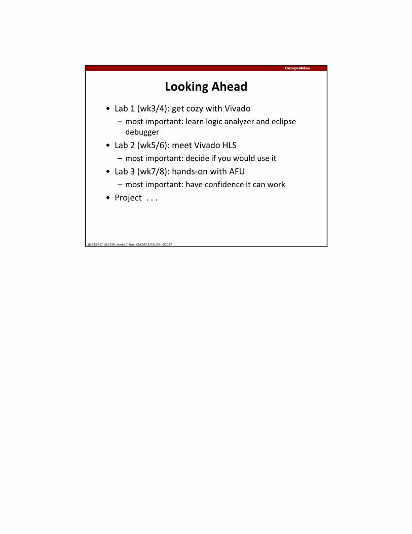
Looking Ahead
• Lab 1 (wk3/4): get cozy with Vivado
– most important: learn logic analyzer and eclipse debugger
• Lab 2 (wk5/6): meet Vivado HLS
– most important: decide if you would use it
• Lab 3 (wk7/8): hands‐on with AFU
– most important: have confidence it can work
• Project . . .