1745-850, Timer-Counter Access Terminal User's … Instruction Various abbreviations and symbols...
68
ALLEN-BRADLEY A ROCKWELL INTERNATIONAL COMPANY User's Manual
Transcript of 1745-850, Timer-Counter Access Terminal User's … Instruction Various abbreviations and symbols...

ALLEN-BRADLEY A ROCKWELL INTERNATIONAL COMPANY
User's Manual
IMPORTANT INFORMATION
Solid state equipment has operational characteristics differing from those of electromechanical equipment. Because of this, and also because of the wide variety of uses for solid state equipment, all persons responsible for applying this equipment must satisfy themselves that each intended application of this equipment is acceptable. In no event will Allen-Bradley Company be responsible or liable for indirect or consequential damages resulting from the use or application of this equipment. The examples and diagrams in this manual are included solely for illustrative purposes. Because of the many variables and requirements associated with any particular installation, Allen- Bradley Company cannot assume responsibility or liability for actual use based on the examples and diagrams. No patent liability is assumed by Allen-Bradley Company with respect to use of information, circuits, equipment, or software described in this manual. Reproduction of the contents of this manual, in whole or in part, without written permission of the Allen-Bradley Company is prohibited. 0 1986 Allen-Bradley Company
WARNING and CAUTION Boxes
WARNINGS indicate that people may be hurt if procedures are not followed properly. CAUTIONS indicate that machinery may be damaged or economic loss can occur if procedures are not followed properly. Both WARNINGS and CAUTIONS
0 Identify a possible trouble spot 0 Tell what causes the trouble 0 Give the result of improper action 0 Tell how to avoid trouble
Page
1-1
Chapter Objectives . . . . . . . . . . . . . . . . . 2-1 The Equipment . . . . . . . . . . . . . . . . . . . 2-1 TCAT . Features . . . . . . . . . . . . . . . . . . 2-2 Optional RemoteCommunication Kit . . . . . 2-4
Chapter Objectives . . . . . . . . . . . . . . . . 3-1 Keyboard . . . . . . . . . . . . . . . . . . . . . . 3-1 Mode Selection . . . . . . . . . . . . . . . . . . . 3-2 Displays . . . . . . . . . . . . . . . . . . . . . . . 3-2
Display Instruction Symbols . . . . . . . . . 3-3 Error Codes . . . . . . . . . . . . . . . . . . . . . 3-4 Operating the TCAT . . . . . . . . . . . . . . . . 3-5 Power-Up . . . . . . . . . . . . . . . . . . . . . . . 3-5
Power-Up Using Address 867 . . . . . . . . 3-8
Using the NEXT Key . . . . . . . . . . . . . . 3- 10 Using the CANCEL Key . . . . . . . . . . . . . 3-11 Using the PRESET. ACCUM. and STEP Keys 3-12 Protected PR and AC Values . . . . . . . . . . 3- 12
Using the Address Key . . . . . . . . . . . . . . 3-9
Chapter Objectives . . . . . . . . . . . . . . . . . 4-1 Displays Review . . . . . . . . . . . . . . . . . . . 4-1 RTO and RTF Timer Characteristics . . . . . . . 4-2 CTU and CTD Counter Characteristics . . . . . 4-3 Monitoring a Timer Instruction . . . . . . . . . 4-4 Monitoring a Counter Instruction . . . . . . . . 4-5 Modifying a Timer Instruction . . . . . . . . . . 4-6 Modifying a Counter Instruction . . . . . . . . 4-7 Using ENTER Key to Reset AC Value to Zero . 4-8

Chapter Title Page
5 Sequencer Instructions
Chapter Objectives . . . . . . . . . . . . . . . . . 5-1
Monitoring a Sequencer Instruction . . . . . . 5-3 Modifying a Sequencer Step . . . . . . . . . . . 5-4
SQO and SQI Sequencer Characteristics . . . . 5-1
6 Monitoring Inputs and Outputs
Chapter Objectives . . . . . . . . . . . . . . . . 6-1
Address Group Numbers . . . . . . . . . . . . . 6-1 The TCAT Group Number Display . . . . . . . . 6-3 Monitoring Group NumberAddresses . . . . . 6-4
i/O Monitoring Capabilities of the TCAT . . . 6-1
7 Specifications . . . . . . . . . . . . . . . . . 7-1
8 Installation
Chapter Objectives . . . . . . . . . . . . . . . . 8-1 Equipment Checkout . . . . . . . . . . . . . . . 8-1 Enclosure Considerations . . . . . . . . . . . . . 8-2 Mounting . . . . . . . . . . . . . . . . . . . . . . 8-3 Connecting the Cable . . . . . . . . . . . . . . . 8-4 Mounting Template . . . . . . . . . . . . . . . 8-5 Cleaning Recommendations . . . . . . . . . . . 8-6
Appendices A -Using Fine Time Base Contacts . . . . . . A-1 B -Special Sequencer Instructions . . . . . . 6-1 C-Shift Register instructions . . . . . . . . . C-1 D . EEPROM Memory Module . . . . . . . . . D-1 E -Mounting Template . . . . . . . . . . . . . E-1

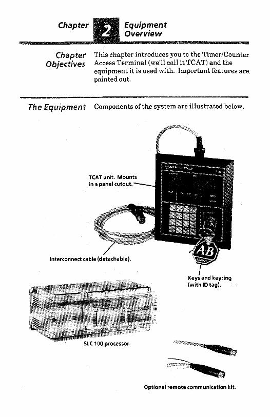
The TimerKounter Access Terminal (TCAT) is used with the SLC 100 Programmable Controller. I t is designed for mounting in a panel cutout, usually the door of the controller enclosure. With the SLC 100 controller in the Run mode, the TCAT provides access to programmed timer, counter, and sequencer data. This allows production, supervisory, and maintenance people to monitor this data “on-line”.
Data can also be modified to accomodate a process or part change. A keyswitch helps prevent unauthorized modifications.
This manual points out important features of the TCAT, then goes on to discuss operating details as they apply to timerlcountertsequencer data, and the monitoring of I/O addresses.
You don’t need a detailed knowledge of programming to use the TCAT.

~~~~~~~ This chapter introduces you to the TimerICounter
equipment it is used with. Important features are pointed out.
~ ~ ~ ~ ~ ~ w @ ~ Access Terminal (we'll call it TCAT) and the
Interconnect ca
Components of the system are illustrated below.
ii;: *I _,
K A T unit. Mounts in a panel cutout. -
lble (detachable).
Optional remote communication kit.

TCA T - features The following features are pointed out in the illustration on Page 2-3. Programming termi- nology is explained in more detail in Chapter 3. Installation information appears in Chapter 8.
1. Keyswitch. You must use the key to operate the TCAT in the modify mode. This helps prevent unauthorized program modifications. Keyswitch cover protects keyslot.
2. Keys and keyring. For your convenience, error codes are printed on the keyring ID tag.
3. Keyboard. Used to access and enter data and addresses. Keys have positive, tactile feedback.
4. Address display. 3-character digital display shows addresses and other information.
5 . Data display. 4-character digital display shows PR and AC values, and other information.
6. Instruction indicators. TME (green) indicates an RTO or RTF timer. CNT (green) indicates a CTU or CTD counter. SEQ (green) indicates an SQO or SQI sequencer.
7. Protect (PROT) status indicator. This red indicator is lit if the monitored instruction or sequencer step is protected in the program.
8. Data indicators. PRESET (green) indicates a preset (PR) value. ACCUM (green) indicates an accumulator (AC) value.
9. Error code table. Listed in English and French.
10. Mounting screws (4). The TCAT mounts in an enclosure or panel cutout. See Chapter 8.
11. Cable socket (labeled CCl). Plug the interconnect cable (supplied) into this socket and the programmer socket on the SLC processor. Refer to Chapter 8, Installation.

2-3
Address -- display.
Protect status indicator. - Instruction/ indicators.
Keyboard..
-(5) Data display.
4 8 ) Data indicators.
.(1) Keyswitch.
i

O p t i O d Remote The remote communication kit (Catalog No. Communjcati.ion 1745-N2) allows you to locate the TCAT at a
#it remote distance (up to 4000 feet) from the SLC 100 controller. For distances beyond 100 feet, a Series B SLC 100 controller is required. The kit consists of two unassembled DIN connec- tors, pointed out in the figure below. You must provide the cable and a suitable power supply. The kit is supplied with an instruction sheet to guide you thru the assembly and installation procedures. Cable and power supply specifications are included.
+- 4000 feet max. r/ Remote Communication Kit
Consists of these two DIN connectors(unassemb1ed)
Controller
AC input
aptea This chapter will show you the operating features of the TCAT in detail. Programming terminology will be explained. Error codes will be defined. This will prepare you to perform the keystroke examples in Chapters 4,5, and 6.
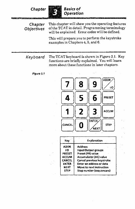
The TCAT keyboard is shown in Figure 3.1. Key functions are briefly explained. You will learn more about these functions in later chapters.
Figure 3.1
Key Explanation
ADDR Address 110 InputIOutput groups
PRESET
Enter an address or data ENTER Cancel previous keystroke CANCEL Accumulator (AC) value ACCUM Preset (PR)value
NEXT Move to next instruction STEP Step number (sequencers)
I I

/bk& S@/ectiof) The keyswitch is shown at the right. The keyslot is vertical, indicating the MONITOR mode is in effect. The TCAT will operate in this mode with the key inserted or removed. With the key inserted and turned clockwise 90" (keyslot horizontal), MONITOR the MODIFY mode is in effect. The key cannot be removed in this mode.
ro MODIFY
Displays Figure 3.2 shows the digital displays and LED indicators of the TCAT. The figure depicts a typical display.
Figure 3.2
I ADDRESS
1 9 0 I
Abbreviations
PROT - Protected SEQ - Sequencer TME -Timer PRESET - Preset (PR) Value CNT - Counter ACCUM -Accumulator (AC) Value
Explanation of displays and LED indicators In this typical display, the TME indicator is lit, telling us that a timer is being monitored. The ADDRESS display indicates the timer address to be 901.
The ACCUM indicator is lit, telling us that the AC value is being monitored. The DATA display shows the AC value to be 999.9.
The PROT indicator is lit, telling us that the timer is protected (the AC or PR value cannot be modified).
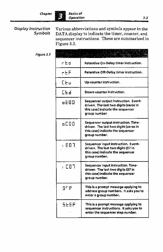
Display Instruction Various abbreviations and symbols appear in the Symbols DATA display to indicate the timer, counter, and
sequencer instructions. These are summarized in Figure 3.3.
Figure 3.3
r t o
r t F
[ t u
C t d
o E U U
O C U I l
I E O 1
I C O l
9'P
5 t E P
Retentive On-Delay timer instruction.
Retentive Off-Delay timer instruction.
Up-counter instruction.
Down-counter instruction.
Sequencer output instruction. Event- driven. The last two digits (zeros in this case) indicate the sequencer group number.
Sequencer output instruction. Time- driven. The last two digits (zeros in this case) indicate the sequencer group number.
Sequencer input instruction. Event- driven. The last two digits (07 in this case) indicate the sequencer group number.
Sequencer input instruction. Time- driven. The last two digits (07 in this case) indicate the sequencer group number.
This is a prompt message applying to address group numbers. It asks you to enter a group number.
This is a prompt message applying to sequencer instructions. It asks you to enter the sequencer step number.
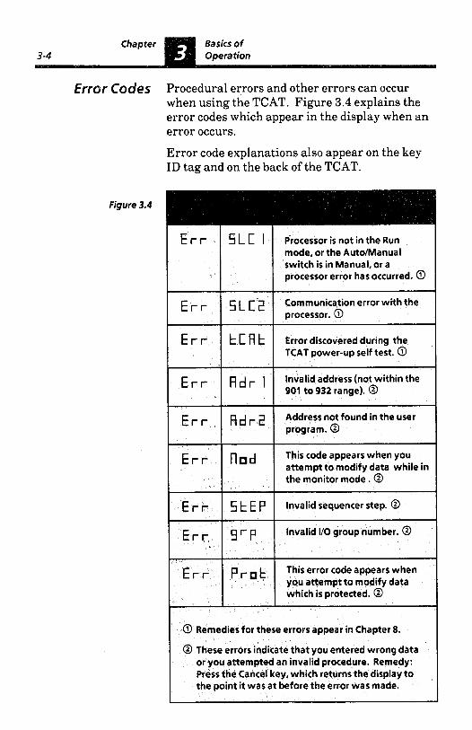
Error Codes Procedural errors and other errors can occur when using the TCAT. Figure 3.4 explains the error codes which appear in the display when an error occurs. Error code explanations also appear on the key ID tag and on the back of the TCAT.
Figure 3. 4
mode, or the Auto/Manual switch is in Manual, or a processor error has occurred. @
E 5 L c 2 Communication error with the processor. 0
E r r k c k Error discovered during the TCAT power-up self test. 0
Invalid address (not within the 901 to 932 range). @ E 1 d I
E fl d 2 Address not found in the user program. 0
This code appears when you attempt to modify data while in the monitor mode. @
E n d
E r r 5 t E p Invalid sequencer step. @
E 9 r p Invalid I/O group number. @
E p t This error code appears when you attempt to modify data which is protected. @
@ Remedies for these errors appear in Chapter 8.
@ These errors indicate that you entered wrong data or you attempted an invalid procedure. Remedy: Press the Cancel key, which returns the display to the point it was at before the error was made.
Opera tin9 the The following TCAT operating details will be TCA T easier to learn if you have access to a TCAT
demonstrator unit connected to an SLC 100 demonstrator unit. We recommend that you read the following paragraphs, then verify the procedures by practicing them on the demonstrator.
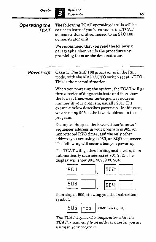
Power-Up Case 1. The SLC 100 processor is in the Run mode, with the MAN/AUTO switch set at AUTO. This is the normal situation. When you power-up the system, the TCAT will go thru a series of diagnostic tests and then show the lowest timer/counter/sequencer address number in your program, usually 901. The example below describes power-up. In this case, we are using 905 as the lowest address in the program. Example: Suppose the lowest timer/counter/ sequencer address in your program is 905, an unprotected RTO timer, and the only other address you are using is 930, an SQO sequencer. The following will occur when you power-up: The TCAT will go thru its diagnostic tests, then automatically scan addresses 901-932. The display will show 901,902,903,904:
then stop at 905, showing you the instruction symbol: F] (TME indicator lit)
The TCAT keyboard is inoperative while the TCAT is scanning to an address number you are using in your program.

Power-Up To move to your next instruction, you simply (continued) press the NEXT key. If you do this while the
TCAT is still scanning, the display will again show the addresses. You might happen to pick up the scan at address 928; the display would show 928,929:
then stop at 930:
(.EOOi (SEQ indicator lit)
Any time you press the NEXT key after the scan is completed, the TCAT shows (in sequence) only those instructions you are using in the program. In this case, pressing NEXT repeatedly would alternately show instructions 905 and 930. Case 2. The SLC 100 processor is in the Run mode, with the MAN/AUTO switch set at MAN. When you power-up the system, the TCAT will go thru its diagnostic tests and then display: --
I E r r I I ~ L C I I
To clear this error, turn the processor AUTO/MAN switch to AUTO. The TCAT will then scan addresses as described in Case 1.
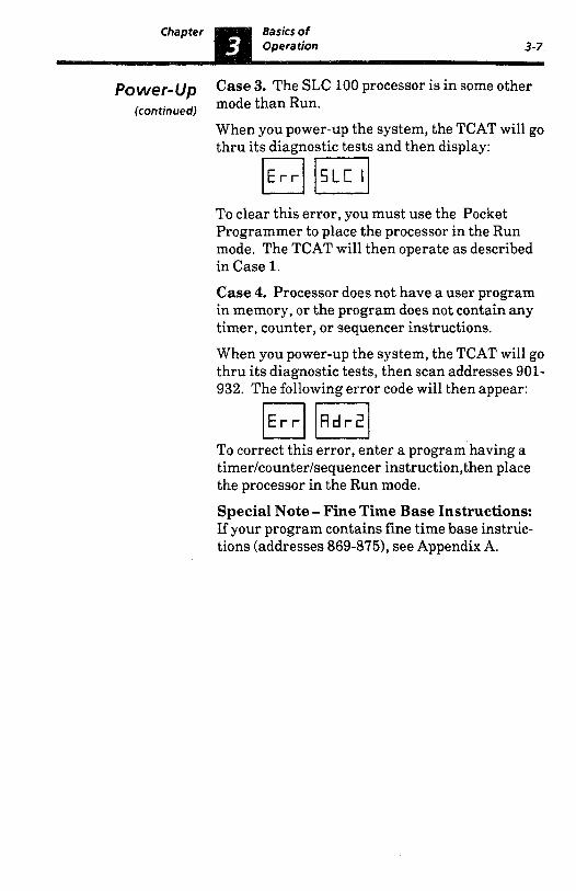
Power-Up Case 3. The SLC 100 processor is in some other (continued)
mode than Run. When you power-up the system, the TCAT will go thru its diagnostic tests and then display:
To clear this error, you must use the Pocket Programmer to place the processor in the Run mode. The TCAT will then operate as described in Case 1.
Case 4. Processor does not have a user program in memory, or the program does not contain any timer, counter, or sequencer instructions. When you power-up the system, the TCAT will go thru its diagnostic tests, then scan addresses 901- 932. The following error code will then appear:
/Rdr21 To correct this error, enter a program having a timer/counter/sequencer instruction,then place the processor in the Run mode. Special Note - Fine Time Base Instructions: If your program contains fine time base instruc- tions (addresses 869-8751, see Appendix A.
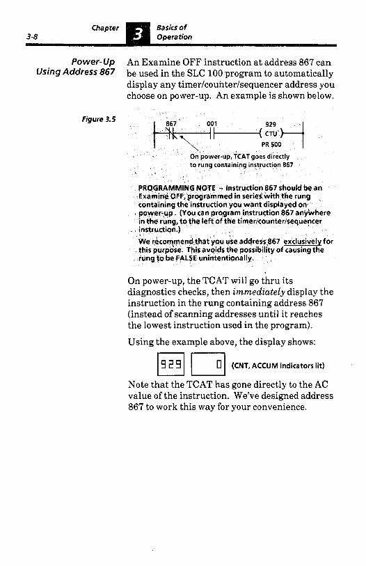
On power-up, the TCAT will go thru its diagnostics checks, then immediately display the instruction in the rung containing address 867 (instead of scanning addresses until it reaches the lowest instruction used in the program).
Using the example above, the display shows:
m u 0 (CNT, ACCUM indicators lit)
Note that the TCAT has gone directly to the AC value of the instruction. We’ve designed address 867 to work this way for your convenience.
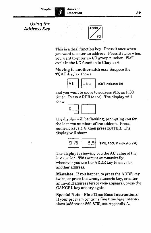
Using the Address Key
This is a dual function key. Press it once when you want to enter an address. Press it twice when you want to enter an I/O group number. We’ll explain the YO function in Chapter 6.
Moving to another address: Suppose the TCAT display shows
(CNT indicator lit)
and you want to move to address 915, an RTO timer. Press ADDR (once). The display will show:
The display will be flashing, prompting you for the last two numbers of the address. Press numeric keys 1,5, then press ENTER. The display will show:
Eli 2 .!? (TME, ACCUM indicators lit)
The display is showing you the AC value of the instruction. This occurs automatically, whenever you use the ADDR key to move to another address. Mistakes: If you happen to press the ADDR key twice, or press the wrong numeric key, or enter an invalid address (error code appears), press the CANCEL key and try again. Special Note - Fine Time Base Instructions: If your program contains fine time base instruc- tions (addresses 869-8751, see Appendix A.

Using the NEXT Key [Z]
This key performs both the NEXT and ENTER functions. In the paragraph on Power-Up (Page 3-6), we used it to move to the next address in the user program. In the paragraph on Using the Address Key (Page 3-9), we used it to enter an address. In the following paragraph, we’ll show you how to use the NEXT key to move thru the timer/ counterlsequencer addresses in the user program. In Chapter 6 on monitoring inputs and outputs, we will show you how to use the NEXT key to move thru address group numbers. Moving to the next address: Suppose your program has a timer, a counter, and a sequencer. The addresses are 905,909, and 924 respectively. The display is showing the preset value of the timer: nu
m u 9 0 5 3 0.0 (TME, PRESET indicators lit)
Press the NEXT key. The display will show
7 0 0 (CNT, PRESET indicators lit)
The display has moved to the counter instruction, and it is showing the preset value. Press NEXT again. The display will show the sequencer:
PI] (SEQ, PRESET indicators lit)
The display is showing the preset value of the current step.
3-1 1
Using the Two things are important to remember here: NEXT Key 0 Pressing the NEXT key shows you the
(continued) addresses in numerical order, even if they do not appear in numerical order in the user program. When moving to the next address, the display shows the same type of information that was shown previously. In this case it is the preset value. It could also be the AC value or the instruction symbol.
Special Note - Fine Time Base Instructions: If your program contains fine time base instruc- tions (addresses 869-8751, see Appendix A.
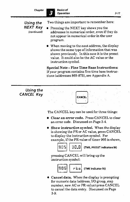
Using the CANCEL Key
CANCEL
The CANCEL key can be used for three things: Clear an error code. Press CANCEL to clear an error code. Discussed on Page 3-4.
Show instruction symbol. When the display is showing the PR or AC value, press CANCEL to display the instruction symbol. For example, if the PR value of timer 905 is shown, nu q 0 5 3 0.0 (TME, PRESET indicators lit)
pressing CANCEL will bring up the instruction symbol:
(1 (TME indicator lit)
0 Cancel data. When the display is prompting for numeric data (address, I/O group, step number, new AC or PR value) press CANCEL to cancel the data entry. Discussed on Page 3-9.
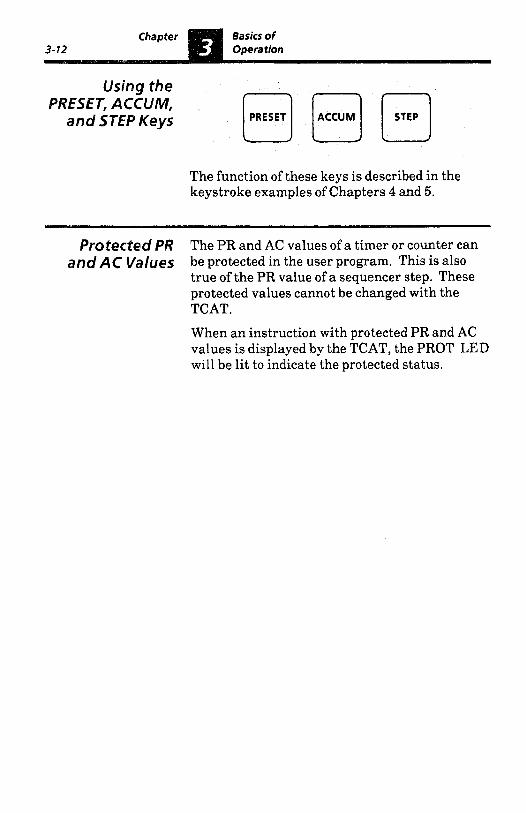
Using the PRESET, ACCUM,
and STEP Keys
The function of these keys is described in the keystroke examples of Chapters 4 and 5.
Protected PR The PR and AC values of a timer or counter can
true of the PR value of a sequencer step. These protected values cannot be changed with the TCAT. When an instruction with protected PR and AC values is displayed by the TCAT, the PROT LED will be lit to indicate the protected status.
and AC Values be protected in the user program. This is also
Timer and Counter
Chapter In this chapter, you will be using the PRESET Objectives and ACCUM keys to monitor and modify the PR
and AC values of a timer and counter instruction.
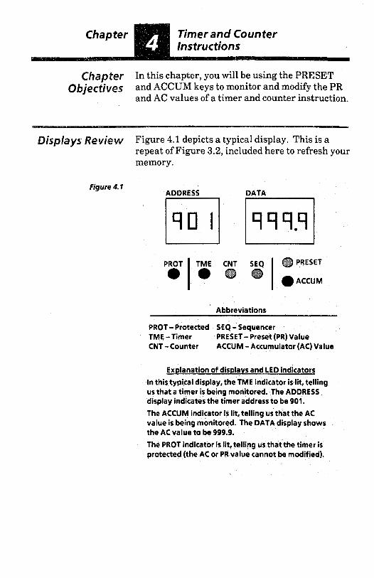
Displays Review Figure 4.1 depicts a typical display. This is a repeat of Figure 3.2, included here to refresh your memory.
Figure 4.1 ADDRESS DATA
Abbreviations
PROT- Protected SEQ - Sequencer TME -Timer PRESET- Preset (PR) Value CNT - Counter ACCUM - Accumulator (AC) Value
Explanation of displays and LED indicators In this typical display, the TME indicator is lit, telling us that a timer is being monitored. The ADDRESS display indicates the timer address to be 901.
The ACCUM indicator is lit, telling us that the AC value is being monitored. The DATA display shows the AC value to be 999.9.
The PROT indicator is lit, telling us that the timer is protected (the AC or PR value cannot be modified).

Timer and Counter 4 -2 Instructions
RTO and RTf Timer instructions include the Retentive Timer Timer On-Delay -(RTO)- and the Retentive Timer Off-
Characteristics Delay -(RTF)-. Both require the use of the Reset instruction -(RST)-. The TCAT will access RTO and RTF timers, but not the Reset instruction. Timer instructions are represented by the following symbols:
901 Address: 901-932
-( RTF )- Range: 0.1-999.9 sec. PR 400.0 PR 400.0
Figure 4.2 shows a typical timer ladder diagram. Rung 1 contains the RTO timer instruction. Its address is 901 and its PR value is 300.0. When this rung is TRUE, the AC value is incrementing. When the AC value equals the PR value, rung 2 goes TRUE, producing an output. Rung 3 is the reset rung. When it goes TRUE, the AC value of the timer is reset to zero. With the TCAT, you will be able to locate address 901, identify the instruction as an RTO timer, and monitor and modify its PR and AC values. You will also be able to observe the AC value incrementing when the timer rung is TRUE.
Figure 4.2
Rung 1 c I-( R';: )- PR 300.0
Rung 2 gOwO1l+ Rung 3 "Of-( :T +
RAC 0

CTU
Ckara
and CPD Counter instructions include the Up Counter Counter -(CTU)- and the Down Counter -(CTD)-. Both
cteristics require the use of the Reset instruction -(RST)-. The TCAT will access CTU and CTD counters, but not the Reset instruction. Counter instructions are represented by the following symbols:
901 Address: 901-932 4 CTD )- Range: 1-9999 counts PR 1000 PR 1000
Figure 4.3 shows a typical counter ladder diagram. Rung 1 contains the CTU counter instruction. Its address is 910 and its PR value is 888. When this rung makes a FALSE to TRUE transition, the AC value increases by one. When the AC value equals the PR value, rung 2 goes TRUE, producing an output. Rung 3 is the reset rung. When it goes TRUE, the AC value of the counter is reset to ten. With the TCAT, you will be able to locate address 910, identify the instruction as a CTU counter, and monitor and modify its PR and AC values. You will also be able to observe the AC value increment with each FALSE to TRUE transition of rung 1.
Figure 4.3
Rung 2
Rung 3 RAC 10
mer and Counter
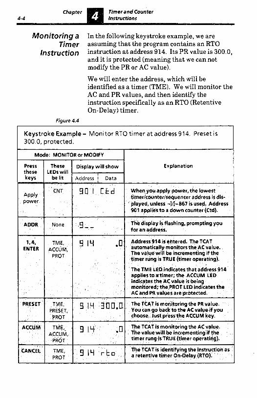
Monitoring a In the following keystroke example, we are Timer assuming that the program contains an RTO
/nstroction instruction a t address 914. Its PR value is 300.0, and it is protected (meaning that we can not modify the PR or AC value). We will enter the address, which will be identified as a timer (TME). We will monitor the AC and PR values, and then identify the instruction specifically as an RTO (Retentive On-Delay) timer.
Figure 4.4
Keystroke Example - Monitor RTO timer at address 914. Preset is 300.0, protected.
Timer and Counter
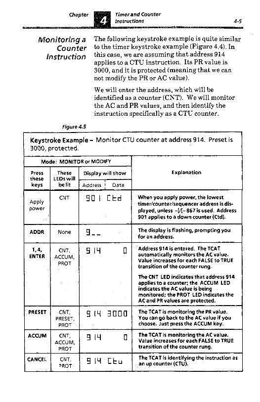
~~~~0~~~~ a The following keystroke example is quite similar
Figure 4.5
to the timer keystroke example (Figure 4.4). In this case, we are assuming that address 914 applies to a CTU instruction. Its PR value is 3000, and it is protected (meaning that we can not modify the PR or AC value). We will enter the address, which will be identified as a counter (CNT). We will monitor the AC and PR values, and then identify the instruction specifically as a CTU counter.
Keystroke Example - Monitor CTU counter at address 914. Preset is 3060, protected..
Mode: MONITOR or MODIFY T Press these keys -
Apply power
ADDR
1.4, ENTER
- PRESET
ACCUM
- CANCEL
These LEDs will
be lit
CNT
None
CNT, ACCUM,
PROT
CNT, PRESET, PROT
CNT, ACCUM,
PROT
CNT, PROT
Display will show
Address i Data I
9 0 I C t d
9 1 1 1 0
9 19 0
9 I 1 1 [tu
Explanation
When you apply power, the lowest timer/counter/sequencer address is dis- played, unless -I/[- 867 is used. Address 901 applies to a down counter (Ctd).
The display is flashing, prompting you for an address.
Address 914 is entered. The TCAT automatically monitors the AC value. Value increases for each FALSE to TRUE transition of the counter rung.
The CNT LED indicates that address 914 applies to a counter; the ACCUM LED indicates the AC value is being monitored; the PROT LED indicates the AC and PR values are protected.
The TCAT is monitoring the PR value. You can go back to the AC value if you choose. Just press the ACCUM key.
The TCAT is monitoring the AC value. Value increasesfor each FALSE to TRUE transition of the counter rung.
The TCAT is identifying the instruction as an up counter (CTU).

Timer and Counter
Modifying a Figure 4.6 will show you how to modify timer Timer data. We assume that the program contains a n
/nstructjon RTO instruction at address 901. Its PR value is 100.0, and its AC value is 999.9. The PR and AC values are not protected. The keystroke example begins with the TCAT display showing the PR value (you learned how to do this in the previous keystroke examples). We will change the PR value to 300.0, then go on to the AC value and change that to 222.2. Note that the TCAT must be in the MODIFY mode to make these changes.
Figure 4.6
Keystroke Example - Modify RTO timer at address 901. PR value is 100.0. AC d u e is 999.9. PR and AC values are not protected.
Mode: MODIFY
1 keys 1 zit, Press These these LEDs will
PRESET PRESET
Display will show
Address I Data
Explanation 1
9 0 I I 0 0.0 display the PR value of timer 901. To You have just pressed the PRESET key to
change the PR value, press PRESET again.
9 0 I ---.- The four underlines are flashing, prompting you to enter a new PR value. I 3.0.0.0 1 TME, 1 9 c] I 3 0 0.0 1 The PRvalue ischanged to300.0.
ENTER PRESET
ACCUM The current AC value of 999.9 is 9 0 I g 9 g .g TME, ACCU M displayed. We assume that the AC value
To enter a new AC value, press ACCUM a is not incrementing (timer rung FALSE)
second time.
ACCUM 9 0 1 - - - .- The four underlines are flashing, prompting you to enter a new AC value.
2,2,2,2 The AC value is changed to 222.2. g 0 I 2 2 2 .z TME, ENTER ACCUM
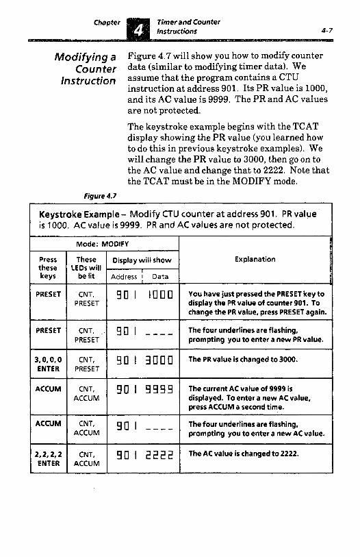
Figure 4.7 will show you how to modify counter data (similar to modifying timer data). We assume that the program contains a CTU instruction at address 901. Its PR value is 1000, and its AC value is 9999. The PR and AC values are not protected. The keystroke example begins with the TCAT display showing the PR value (you learned how to do this in previous keystroke examples). We will change the PR value to 3000, then go on to the AC value and change that to 2222. Note that the TCAT must be in the MODIFY mode.
Figure 4.7
- Modify CTU counter at address 901. PR value i s 1000. AC value is 9999. PR and AC values are not protected.
Mode: MODIFY
Explanation
You have just pressed the PRESET key to display the PR value of counter 901. To change the PR value, press PRESET again.
The four underlines are flashing, prompting you to enter a new PR value.
The PR value is changed to 3000.
The current AC value of 9999 is displayed. To enter a new AC value, press ACCUM a second time.
ACCUM The four underlines are flashing, prompting you to enter a new AC value.
2,2,2,2 ACCUM ENTER
The AC value is changed to 2222. g 0 I 2 2 2 2 CNT,
-

Timer and Counter
Using the ENTER Figure 4.8 will show you how to use the ENTER ~e~ to Reset the key to change the AC value of a timer to zero (the A c value to Zero PR value can be changed to zero in the same
way). Arbitrarily, we have specified that the AC value is incrementing. The AC value (and PR value) of a counter can be changed to zero in this same way.
Figure 4.8
Keystroke Example- Change the AC value of timer 901 to zero. The AC value i s incrementing. PR and AC values are not protected.
Mode: MODIFY
Press
Address I Data be lit keys I LEDs will these
Explanation Display will show These
ACCUM You have just pressed the ACCUM key. 9 fl I 2 2 2 .z TME, ACCUM The AC value happens to be at 222.2, and
incrementing. Suppose you want to "reset" the AC value to zero.
ACCUM The underlines are flashing, prompting 90 I - --.- TME, ACCUM you to enter a new AC value. To enter a
value of zero, just press ENTER. 1 ENTER I TME, I gfl I The AC value is incrementing from zero. ACCUM

er In this chapter, you will be monitoring the PR 5 and AC values of the individual steps of a
Sequencer instruction. You will also modify the PR value of a sequencer step.
I Sequencer instructions include the Sequencer ~ ~ f f ~ ~ ~ Output -(SQO)- and the Sequencer Input
risfics -(SQI)-. Both require the use of the Reset instruction -(RST)-. The TCAT will access SQO and SQI sequencers, but not the Reset instruction.
Sequencer instructions are represented by the following symbols:
-( )- 4 *QI F 100 stepsmaximurn.
901 Address: 901-932
The Sequencer Output (SQO) instruction can control the ON/OFF status of up to 8 outputs for up to 100 steps. The ON/OFF status of outputs for each step is programmed. The Sequencer Input (SQI) instruction differs from the SQO instruction in that the status of up to 8 inputs is programmed, producing an output only when the status of external inputs matches the programmed data for the particular step. Sequencers can be time-driven or event-driven. With time-driven sequencers, each step functions similar to timer instructions, involving an AC value and a programmed PR value. In the same way, the event-driven sequencer functions similar to counter instructions. You will find further operating details and programming information in the User’s Manual for the SLC 100 Programmable Controller. Here we are concerned only with monitoring the PR and AC values of the individual steps, and modifying PR values.
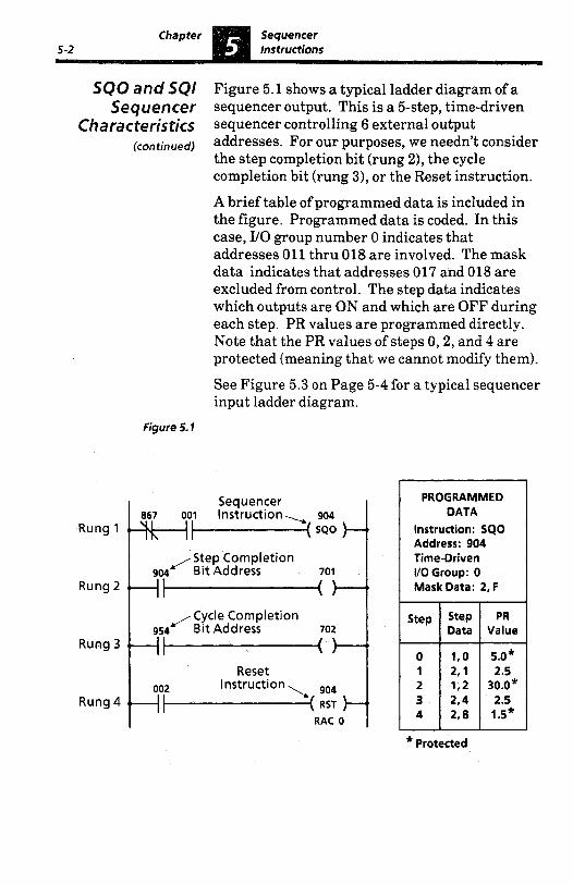
SO0 and SO/ Figure 5.1 shows a typical ladder diagram of a Sequencer sequencer output. This is a 5-step, time-driven
Characteristics sequencer controlling 6 external output (continued) addresses. For our purposes, we needn’t consider
the step completion bit (rung 2), the cycle completion bit (rung 3), or the Reset instruction. A brief table of programmed data is included in the figure. Programmed data is coded. In this case, 110 group number 0 indicates that addresses 011 thru 018 are involved. The mask data indicates that addresses 017 and 018 are excluded from control. The step data indicates which outputs are ON and which are OFF during each step. PR values are programmed directly. Note that the PR values of steps 0,2 , and 4 are protected (meaning that we cannot modify them). See Figure 5.3 on Page 5-4 for a typical sequencer input ladder diagram.
Figure 5.1
Rung 1
Rung 2
Rung 3
Rung 4
Step Completion
/Cycle Completion Bit Address
RAC 0
PROGRAMMED DATA
Instruction: SQO Address: 904 Time-Driven If0 Group: 0 Mask Data: 2, F
* Protected
Chapter Sequencer Instructions 5-3
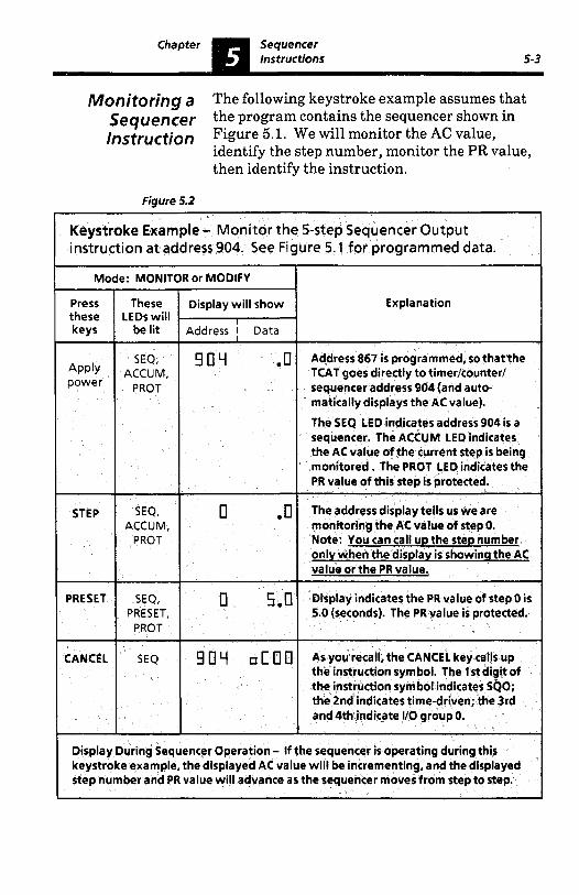
Monitoring a The following keystroke example assumes that sequencer the program contains the sequencer shown in /nstruction Figure 5.1. We will monitor the AC value,
identify the step number, monitor the PR value, then identify the instruction.
Figure 5.2
Keystroke Example - Monitor the 5-step Sequencer Output instruction at address 904. See Figure 5.1 for programmed data.
Mode: MONITOR or MODIFY I
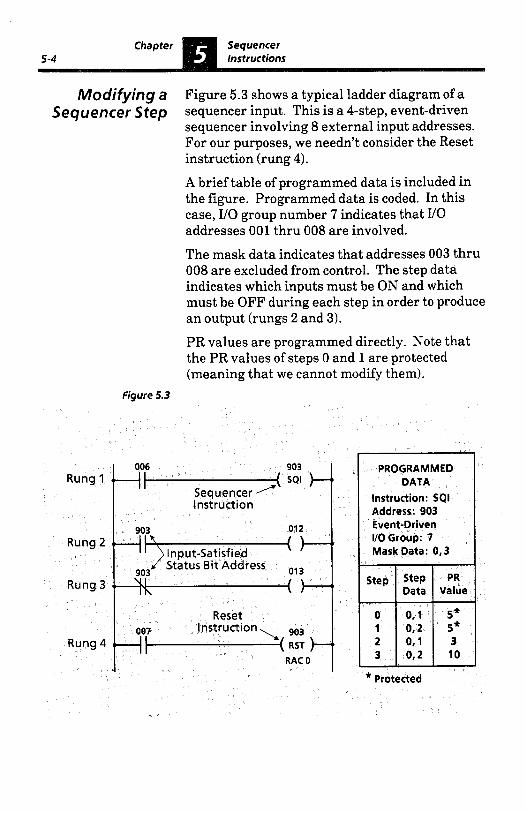

Modifying a The following keystroke example assumes that
Figure 5.3. We will modify the PR value of step 2, then attempt to modify the PR value of step 0.
Sequencer Step the program contains the sequencer shown in
Figure 5.4
Keystroke Example - Modify the Sequencer Input instruction a t address 903. See Figure 5.3 for programmed data. Address 903 is the lowest timer/counter/sequencer address programmed.
Mode: MODIFY
Explanation
Apply power
SEQ the instruction symbol indicates SQI; the Address 903 is displayed. The 1 s t digit of g 03 E 0 1
4th indicate I/O group number 7. 2nd indicates event-driven; The 3rd and
To access a step number, the AC or PR value must first be displayed. We've called up the PR value (protected).
Current step number, 0, is displayed. PRESET, Press STEP again t o select another step. PROT
The display is flashing, prompting you for a steD number.

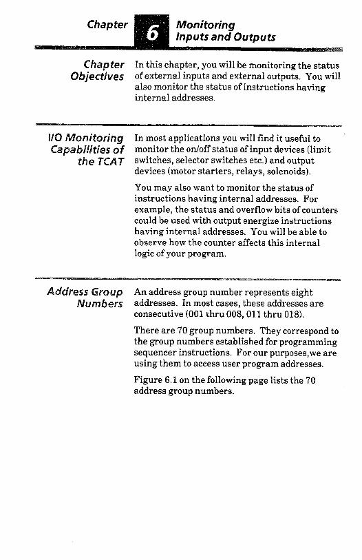
Chapter In this chapter, you will be monitoring the status Objectives of external inputs and external outputs. You will
also monitor the status of instructions having internal addresses.
nitoring In most applications you will find it useful to jlitjes of monitor the ordoff status of input devices (limit
the T ~ A T switches, selector switches etc.) and output devices (motor starters, relays, solenoids). You may also want to monitor the status of instructions having internal addresses. For example, the status and overflow bits of counters could be used with output energize instructions having internal addresses. You will be able to observe how the counter affects this internal logic of your program.
An address group number represents eight
consecutive (001 thru 008,011 thru 018). There are 70 group numbers. They correspond to the group numbers established for programming sequencer instructions. For our purposes,we are using them to access user program addresses. Figure 6.1 on the following page lists the 70 address group numbers.
umbers addresses. In most cases, these addresses are

dress Croup Group number 0 gives you access to addresses of Number5 external outputs of the SLC 100 processor; group
icontjnue~) numbers 1 thru 6 give you access to addresses of external outputs of expansion units. Similarly, group numbers 7 thru 15 give you access to addresses of external inputs of the processor and expansion units. These 16 groups are the most widely used in TCAT applications.
Figure 6.1
Group No.
0 1 2
3 4 5 6
External Addresses Output internal
Addresses
011-016
217-218 211-216 117-118 111-116 017-018
311-316 317-318 41 1-416 41 7-41 8 511-516 517-518 611-616 617-618
Group input No.
External
Addresses
7
201-208 9 101-108 8 001 -008
10 301-308 11 401-408 12
601-608 13 501-508
009-01 0 14 109-110
209-21 0
309-310 15 409-410
509-510 609-61 0
Group Numbers 38 thru 69
Groups 38 thru 69 correspond to addresses 901 thru 932 respectively. They are used in special sequencer instruction techniques. The TCAT display for these group numbers does arepresent external input/output addresses
Group Internal No. Addresses
16
717-724 18 709-716 17 701-708
19 725-732 20 733-740 21 741-748
22 749-756 23 757-764 24 765-772
25 773-780 26 781-788 27 789-796
28 797-804 29 805-812 30 813-820
31 821-828 32 829-836 33 837-844
34 845-852 35 853-860 36 861-868
37 0 869-876
orinternal addresses. instead, it shows you the individual bits of a BCD counter (the count corresponds to the sequencer step number). addresses and the
0 These are fine time base
auto/manual switch bit. -
P Y
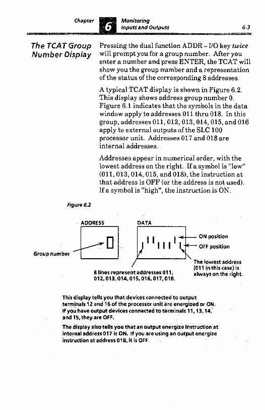
Pressing the dual function ADDR - I/O key twice will prompt you for a group number. After you enter a number and press ENTER, the TCAT will show you the group number and a representation of the status of the corresponding 8 addresses. A typical TCAT display is shown in Figure 6.2. This display shows address group number 0. Figure 6.1 indicates that the symbols in the data window apply to addresses 011 thru 018. In this group, addresses 011,012,013,014,015, and 016 apply to external outputs of the SLC 100 processor unit. Addresses 017 and 018 are internal addresses. Addresses appear in numerical order, with the lowest address on the right. If a symbol is “low” (011,013,014,015, and 0181, the instruction a t that address is OFF (or the address is not used). If a symbol is “high”, the instruction is ON.
Figure 6.2
i(-I1 ~ JT,Al I ,~ The lowest address
8 lines represent addresses 01 1, (01 1 in this case) is
012,013,014,015,016,017,018. always on the right.
ON position
OFF position Group number
This display tells you that devices connected to output terminals 12 and 16 of the processor unit are energized or ON. If you have output devices connected to terminals 11,13,14, and 15, they are OFF.
The display also tells you that an output energize instruction at internal address 017 is ON. If you are using an output energize instruction at address 018, it is OFF.

Monitoring In the following keystroke example, we will Group Number access a group number, use the ADDR - I/O key
Addresses to access another group number, use the NEXT key to access successive group numbers, then return to the original instruction.
Figure 6.3
Keystroke Example - Monitor address group numbers 0, 15, and 17. Return to the original display.
Explanation
contains a down counter at address 901, and address 867 is not used.
~~~~~ ~~
VO, I/O, The display is promting you for a group - - q r p None number.
0. ENTER
None Group 0 is selected. Addresses 01 1,012, 013,014,015,016,017,018are displayed. 012 and 014 are ON.
I I I I I
l/O,I/O, 1.5.
ENTER
None
110. CANCEL
CNT 90 I C t d
Group 15 is selected. Addresses 309, 310,409,410,509,510,609,610are displayed. 409 and 610 are ON.
Pressing the NEXT key twice has moved the display to group 17, applying to internal addresses 709,710,711,712, 713,714,715.716. Instructions at addresses710,713,714,715areON.
Pressing these keys has taken us back to the initial display, the down counter at address 901. We could also have accessed some other timedcounterl sequencer address by pressing UO, the new address, then ENTER.
I I I
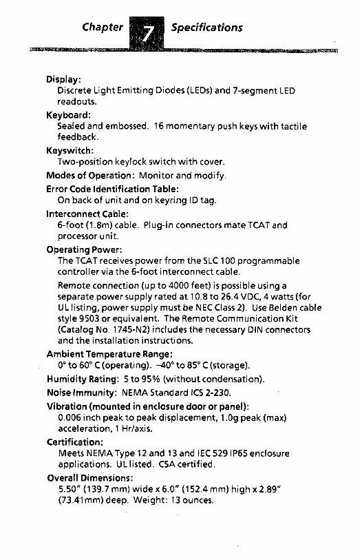
Display: Discrete Light Emitting Diodes (LEDs) and 7-segment LED readouts.
Sealed and embossed. 16 momentary push keys with tactile feedback.
Keyswitch: Two-position keylock switch with cover.
Modes of Operation: Monitor and modify. Error Code Identification Table:
On back of unit and on keyring ID tag. Interconnect Cable:
6-foot (1.8m) cable. Plug-in connectors mate TCAT and processor unit.
Operating Power: The TCAT receives power from the SLC 100 programmable controller via the 6-foot interconnect cable. Remote connection (up t o 4000 feet) is possible using a separate power supply rated a t 10.8 t o 26.4 VDC, 4 watts (for UL listing, power supply must be NEC Class 2) . Use Belden cable style 9503 or equivalent. The Remote Communication Kit (Catalog No. 1745-N2) includes the necessary DIN connectors and the installation instructions.
Ambient Temperature Range: 0"to 60" C (operating). -40" t o 85" C (storage).
Humidity Rating: 5 to 95% (without condensation). Noise Immunity: NEMA Standard ICs 2-230. Vibration (mounted in enclosure door or panel):
Keyboard:
0.006 inch peak to peak displacement, 1 .Og peak (max) acceleration, 1 Hr/axis.
Meets NEMAType 12 and 13 and IEC 529 IP65 enclosure applications. UL listed. CSA certified.
5.50" (139.7 mm) wide x 6.0" (152.4 mm) high x 2.89" (73.41mm) deep. Weight: 13 ounces.
Certification:
Overall Dimensions:


Chapter This chapter explains how to check out the TCAT Objectives prior to installation and how to install the TCAT
in an enclosure cutout.
Equipment Before you install the TCAT, check i t for external Checkout damage which might have occurred during
shipment. Then power it up to check for possible internal damage. To power up the TCAT, you will need access to an energized SLC 100 processor. Power-up procedure: 1. Energize the processor. Place the processor in
the Run mode with the pocket programmer. Turn the Auto/Manual switch to Auto.
2. Disconnect power to the processor. Unplug the pocket programmer.
3. Plug one end of the interconnect cable (supplied with the TCAT) in the socket on the top of the TCAT and the other end in the programmer socket on the processor. Cable connectors are keyed to guard against improper insertion. Make sure the spring latch is engaged to secure the connector in the socket.
4. Energize the processor. The TCAT should operate as described in Chapter 3 on Pages 3-5 to 3-8.
5 . If the TCAT display shows any of the following 3 error messages, follow the procedures listed in Figure 8.1.
E r r 5 L C I E r r 5 L C 2 E r r t C R t
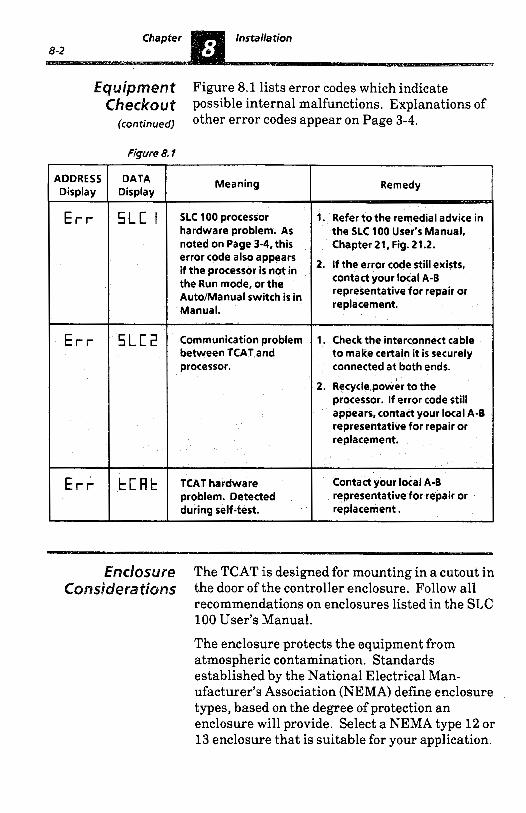
Equipment Figure 8.1 lists error codes which indicate Checkout possible internal malfunctions. Explanations of
other error codes appear on Page 3-4.
Figure 8. ?
ADDRESS Display
E r r
E r r
E r r
DATA Display
5LC I
SLC2
t C R t
Meaning Remedy
SLC 100 processor 1. Refer to the remedial advice in hardware problem. As the SLC 100 User’s Manual, noted on Page 3-4, this Chapter 21, Fig. 21.2. error code also appears if the processor is not in the Run mode, or the Auto/Manual switch is in Manual.
Communication problem 1. Check the interconnect cable between TCAT and to make certain it is securely processor. connected a t both ends.
2. If the error code still exists, contact your local A-B representative for repair or replacement.
2. Recycle power to the processor. If error code still appears, contact your local A-8 representative for repair or replacement.
TCAT hardware Contact your local A-B problem. Detected representative for repair or during self-test. replacement.
Enclosure The TCAT is designed for mounting in a cutout in the door of the controller enclosure. Follow all recommendations on enclosures listed in the SLC 100 User’s Manual.
The enclosure protects the equipment from atmospheric contamination. Standards established by the National Electrical Man- ufacturer’s Association (NEMA) define enclosure types, based on the degree of protection an enclosure will provide. Select a NEMA type 12 or 13 enclosure that is suitable for your application.
Installation 8-3
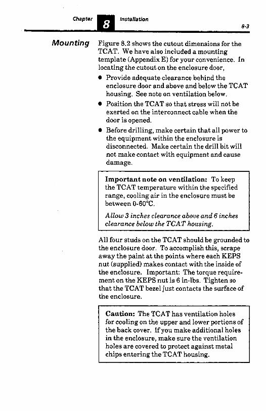
Mounting Figure 8.2 shows the cutout dimensions for the TCAT. We have also included a mounting template (Appendix E) for your convenience. In locating the cutout on the enclosure door,
Provide adequate clearance behind the enclosure door and above and below the TCAT housing. See note on ventilation below. Position the TCAT so that stress will not be exerted on the interconnect cable when the door is opened. Before drilling, make certain that all power to the equipment within the enclosure is disconnected. Make certain the drill bit will not make contact with equipment and cause damage.
Important note on ventilation: To keep the TCAT temperature within the specified range, cooling air in the enclosure must be between 0-60°C.
Allow 3 inches clearance above and 6 inches clearance below the TCAT housing. -
All four studs on the TCAT should be grounded to the enclosure door. To accomplish this, scrape away the paint at the points where each KEPS nut (supplied) makes contact with the inside of the enclosure. Important: The torque require- ment on the KEPS nut is 6 in-lbs. Tighten so that the TCAT bezel just contacts the surface of the enclosure.
Caution: The TCAT has ventilation holes for cooling on the upper and lower portions of the back cover. If you make additional holes in the enclosure, make sure the ventilation holes are covered to protect against metal chips entering the TCAT housing.
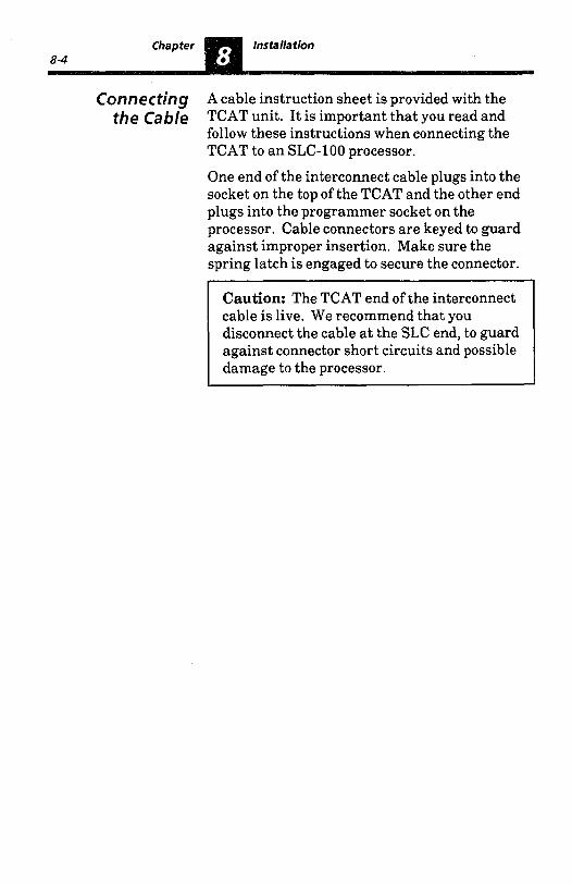
Connecting A cable instruction sheet is provided with the the Cable TCAT unit. It is important that you read and
follow these instructions when connecting the TCAT to a n SLC-100 processor. One end of the interconnect cable plugs into the socket on the top of the TCAT and the other end plugs into the programmer socket on the processor. Cable connectors are keyed to guard against improper insertion. Make sure the spring latch is engaged to secure the connector.
cable is live. We recommend that you disconnect the cable at the SLC end, to guard against connector short circuits and possible damage to the processor.

Figure 8.2
0
0
4.125" (104.8 mm)
3.812" (96.8 mm)
4.50" (114.3 mm)
Approximate cutout and drilling dimensions for the K A T
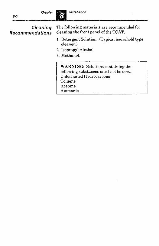
anin9 The following materials are recommended for dons cleaning the front panel of the TCAT.
1. Detergent Solution. (Typical household type
2. Isopropyl Alcohol. 3. Methanol.
cleaner.)
WARNING: Solutions containing the following substances must not be used: Chlorinated Hydrocarbons Toluene Acetone Ammonia
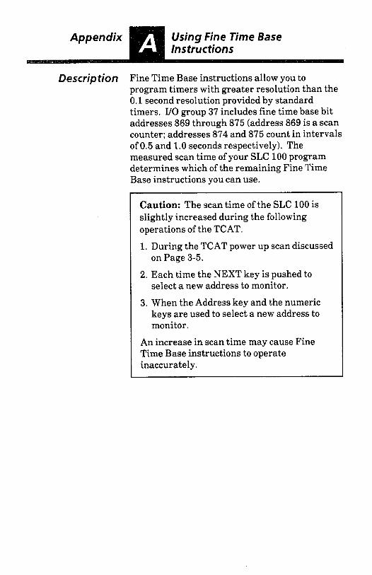
Description Fine Time Base instructions allow you to program timers with greater resolution than the 0.1 second resolution provided by standard timers. I/O group 37 includes fine time base bit addresses 869 through 875 (address 869 is a scan counter; addresses 874 and 875 count in intervals of 0.5 and 1.0 seconds respectively). The measured scan time of your SLC 100 program determines which of the remaining Fine Time Base instructions you can use.
Caution: The scan time of the SLC 100 is slightly increased during the following operations of the TCAT. 1. During the TCAT power up scan discussed
on Page 3-5.
2. Each time the NEXT key is pushed to select a new address to monitor.
3. When the Address key and the numeric keys are used to select a new address to monitor.
An increase in scan time may cause Fine Time Base instructions to operate inaccurately.


Description The SLC 100 sequencer instructions can be used to create:
Cascaded sequencers 0 Reversing sequencers
SQI driving an SQO 0 SQI monitoring an SQO step
Sequencer jump operation Procedures for monitoring/modifying sequencer instructions are explained in Chapter 5. A cascaded sequencer example is shown below.
Cascaded Sequencer instructions can be cascaded to control Sequencer more than 8 bit addresses. These instructions /nstructjon will sometimes share the same addresses, operate
according to the same rung conditions, have the same preset value and have the same number of steps. An example of this type of cascaded sequencer is illustrated in the figure below.
Special Sequencer E-2
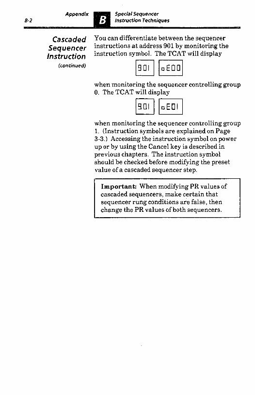
Cascaded You can differentiate between the sequencer Sequencer instructions at address 901 by monitoring the Instruction instruction symbol. The TCAT will display
(continued)
when monitoring the sequencer controlling group 0. The TCAT will display
when monitoring the sequencer controlling group 1. (Instruction symbols are explained on Page 3-3.) Accessing the instruction symbol on power up or by using the Cancel key is described in previous chapters. The instruction symbol should be checked before modifying the preset value of a cascaded sequencer step.
Important: When modifying PR values of cascaded sequencers, make certain that sequencer rung conditions are false, then change the PR values of both sequencers.

step Number When programming reversing sequencers, SQI
operation, special sequencer groups 38 through 69 must be used. Special sequencer groups 38 through 69 are binary counters that display the current step number for the operation. The step number is displayed in binary notation with the least significant digit in the far right position. Figure B.2 below illustrates this.
Display monitoring an SQO step, and the sequencer jump


Description With a shift register instruction, status data enters an &bit register and is automatically shifted through the register from one bit address to the next on a time or event-driven basis. A sequencer instruction is used to control the shift rate as shown in the figure below.
Figure C. 1
Rung 1
Rung 2
Rung4 ZCL
< , G b ( y: Rung 3
4q- ZCL Step clock 0 rate preset: Shift
Tirne-driven Group no.: Any
Step 0 data: Any
Tirne-driven shift right register -The TCAT can be
shift clock rate. used to modify the preset value of step 0 which is the
The shift clock rate of a shift register instruction can be modified with the TCAT. In the figure above, the shift register a t address 18 is controlled by sequencer 901. The preset value of sequencer 901 controls the shift clock rate. This preset can be modified with the TCAT. See the keystroke example for modifying sequencer steps in Chapter 5 on Page 5-4 for details.

~ ~ S C ~ ~ ~ ~ ~ ~ ~ The EEPROM module is an optional device which plugs into the SLC 100 processor unit. With the EEPROM you can: 0 Save the contents of the RAM memory, for
storage purposes. 0 Load the contents of the EEPROM memory
into the processor RAM. If you have an EEPROM module installed and you have modified data with the TCAT and you wish the modified data to be saved in the EEPROM, you must do so before disconnecting power. Do this by exchanging the TCAT with the pocket programmer and following the procedure described in Chapter 16 of the SLC 100 User’s Manual (Publication 1745-800). After saving the contents of the RAM, you can remove power.


n We’ve provided the following template (3 copies) for your convenience in mounting the TCAT. Before you use the template, read the installation recommendations on Page 8-3.

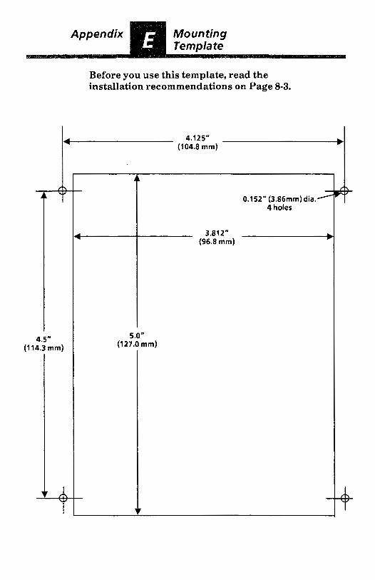
Before you use this template, read the installation recommendations on Page 8-3.
4 4.125" (104.8 mm)
4.5" (1 14.3 mm)
- f - 0.152" (3.86mm)dia.'
4 holes
I (96.8mm)
3.81 2"
5.0" (127.0 mm)


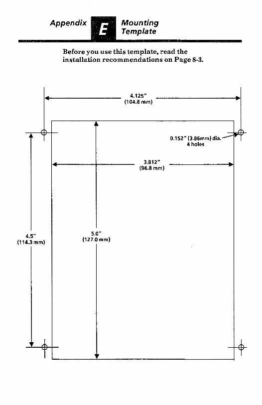
Before you use this template, read the installation recommendations on Page 8-3.
t 4.125" (104.8 mm)
b
4.5" (114.3 mm)
A - -
0.152" (3.86mm) dia.' 4 holes
I (96.8 mm)
3.812"
5.0" (127.0 mm)

Before you use this template, read the installation recommendations on Page 8-3.
4 4.1 25" b
4.5" (1 14.3 mm)
(1 04.8 mm)
A - -
0.152" (3.86mm) dia.' 4 holes
I (96.8 mm)
3.812" +
5.0" (127.0 mm)


ALLEN-BRADLEY A ROCKWELL INTERNATIONAL COMPANY
industrial Control Division Milwaukee, Wisconsin 53204
Publication 1745-850 -April, 1986
@
40065-311-01(A)