17.1 Si31_2001 SI31 Advanced Computer Graphics AGR Lecture 17 Radiosity - Conclusion...
27
17.1 Si31_2001 SI31 Advanced Computer Graphics AGR Lecture 17 Radiosity - Conclusion Non-PhotoRealistic Rendering
-
date post
19-Dec-2015 -
Category
Documents
-
view
224 -
download
3
Transcript of 17.1 Si31_2001 SI31 Advanced Computer Graphics AGR Lecture 17 Radiosity - Conclusion...
17.1Si31_2001
SI31Advanced Computer
GraphicsAGR
SI31Advanced Computer
GraphicsAGR
Lecture 17Radiosity - Conclusion
Non-PhotoRealistic Rendering

17.2Si31_2001
Radiosity - SubstructuringRadiosity - Substructuring
Dilemma:– accuracy in radiosity demands
many, small patches– efficiency in radiosity demands a
few, large patches Substructuring provides a
solution– each patch divided into a number of
subpatches

17.3Si31_2001
Substructuring - Managing the Complexity
Substructuring - Managing the Complexity
Suppose N patches in all, M subpatches in all
What is complexity if we apply radiosity algorithm at subpatch level?
A compromise is to shoot from patchpatch to subpatchsubpatch
What is the resulting complexity?
17.4Si31_2001
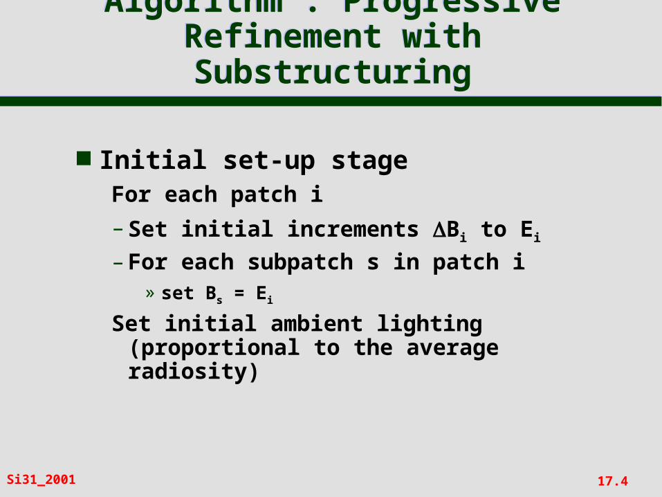
Algorithm : Progressive Refinement with Substructuring
Algorithm : Progressive Refinement with Substructuring
Initial set-up stageFor each patch i
– Set initial increments Bi to Ei
– For each subpatch s in patch i» set Bs = Ei
Set initial ambient lighting (proportional to the average radiosity)

17.5Si31_2001
Algorithm : Progressive Refinement with Substructuring
Algorithm : Progressive Refinement with Substructuring
Select patch i with greatest unshot radiosity BiAi
– build hemicube, calculate form factors Fi-s for all subpatches s in all patches
– for each patch j seen by patch i do
for each subpatch s in j seen by i
Radiosity = Rj Bi Fi-s Ai / As
Bs = Bs + Radiosity
Bj = Bj + Radiosity As/Aj
– Bi = 0
17.6Si31_2001
Algorithm : Progressive Refinement with Substructuring
Algorithm : Progressive Refinement with Substructuring
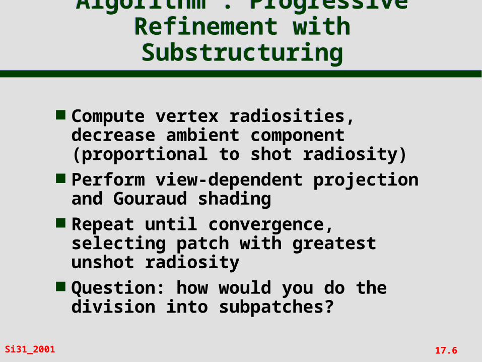
Compute vertex radiosities, decrease ambient component (proportional to shot radiosity)
Perform view-dependent projection and Gouraud shading
Repeat until convergence, selecting patch with greatest unshot radiosity
Question: how would you do the division into subpatches?

17.7Si31_2001
Radiosity - SoftwareRadiosity - Software
Radiosity software is commercially available from:
– Lightwork Design of Sheffield
http://www.lightwork.com– Lightscapehttp://www.lightscape.com
Catalogue of radiosity software:
– http://www.ledalite.com/library-/rad.htm
17.8Si31_2001
Radiosity – Some LinksRadiosity – Some Links
Paul Heckbert’s radiosity page– www.cs.cmu.edu/~radiosity
ACM SIGGRAPH Hypergraph– www.education.siggraph.org/materi
als/HyperGraph/radiosity/radiosity.htm

17.9Si31_2001
Combining Radiosity and Ray Tracing
Combining Radiosity and Ray Tracing

17.10Si31_2001
Non-Photorealistic Rendering
Non-Photorealistic Rendering

17.11Si31_2001
Why Photorealistic?Why Photorealistic?
Simple graphics rendering techniques produce rather dull, ‘dead’ images
Hence the research into achieving greater and greater photorealism– textures– bump mapping– environment mapping– ray tracing– radiosity
This research continues...

17.12Si31_2001
Why Non-Photorealistic?Why Non-Photorealistic?
In real-life, photographs are not always the best imagery
Schematic diagrams more useful in many applications
Artist is often able to convey greater expressiveness than a photographer
This has given rise to the field of non-photorealistic rendering Medical illustration
From IBLS at Univ of Glasgow

17.13Si31_2001
Pen and Ink IllustrationsPen and Ink Illustrations
As an example of this approach, we shall look at computer-generated ‘pen-and-ink’ illustration
17.14Si31_2001
Pen and Ink IllustrationPen and Ink Illustration
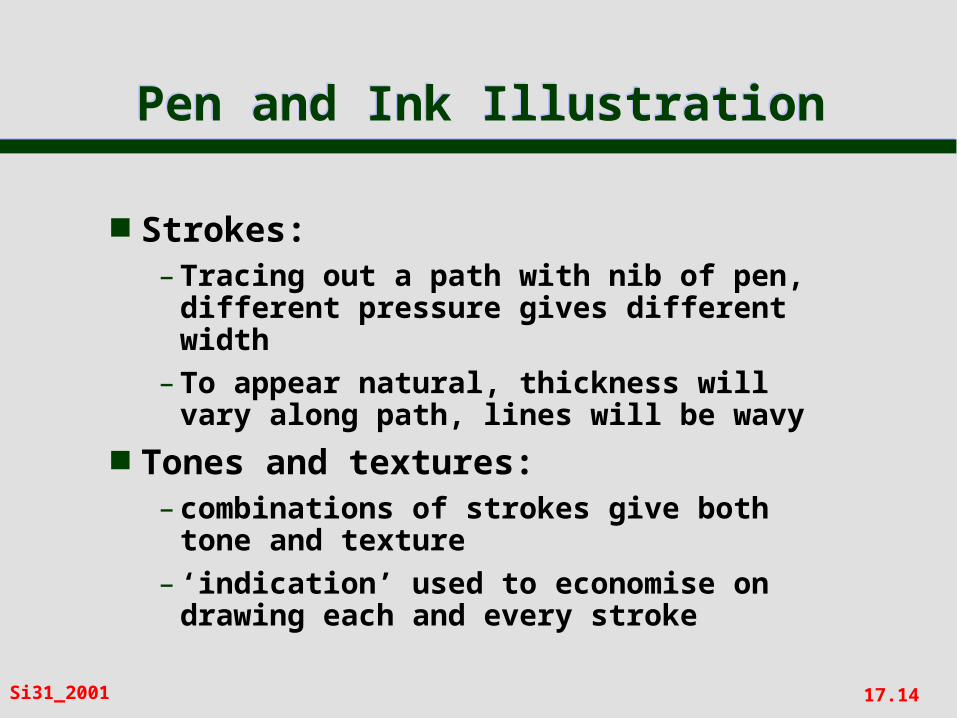
Strokes:– Tracing out a path with nib of pen,
different pressure gives different width
– To appear natural, thickness will vary along path, lines will be wavy
Tones and textures:– combinations of strokes give both
tone and texture– ‘indication’ used to economise on
drawing each and every stroke
17.15Si31_2001
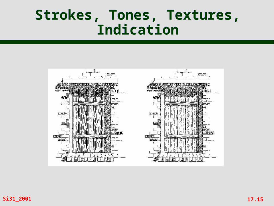
Strokes, Tones, Textures, Indication
Strokes, Tones, Textures, Indication
17.16Si31_2001
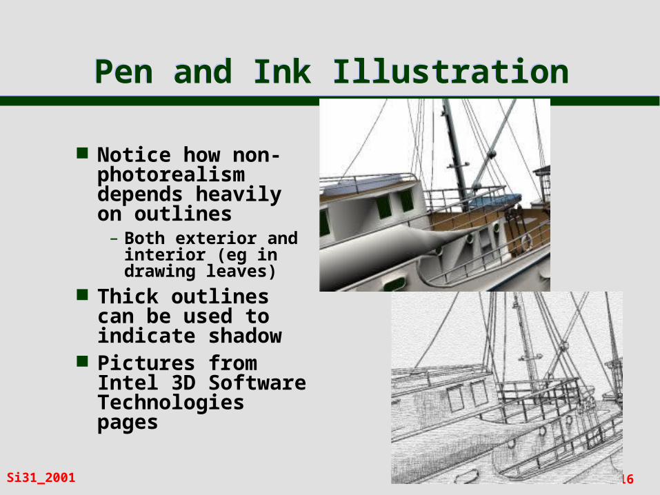
Pen and Ink IllustrationPen and Ink Illustration
Notice how non-photorealism depends heavily on outlines
– Both exterior and interior (eg in drawing leaves)
Thick outlines can be used to indicate shadow
Pictures from Intel 3D Software Technologies pages
17.17Si31_2001
Computer-generated Pen and Ink Illustration
Computer-generated Pen and Ink Illustration
Compared with traditional rendering:– tone and texture combined– 2D projection affects rendering
Pipeline includes:– modelling– texture assignment– reflection model to give tone– outlines added
17.18Si31_2001
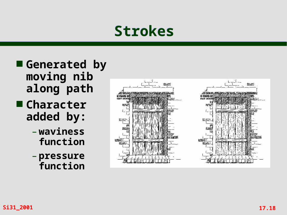
StrokesStrokes
Generated by moving nib along path
Character added by:– waviness
function– pressure
function

17.19Si31_2001
Stroke TexturesStroke Textures
Collection of strokes to give texture and tone
Prioritised so that different tones can be achieved– first only highest priority drawn– to increase tone, lower priorities drawn
For example:– highest priority to outline– next could be horizontal lines– then vertical, and so on

17.20Si31_2001
Stroke TexturesStroke Textures

17.21Si31_2001
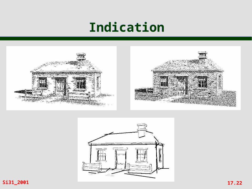
IndicationIndication
This can be handled semi-automatically by marking on drawing a set of ‘indicator lines’
Strokes closer to indicator lines have higher probability of being drawn
17.22Si31_2001
IndicationIndication

17.23Si31_2001
IndicationIndication

17.24Si31_2001
OutlineOutline
Boundary and interior outlines Boundary outline texture
associated with each stroke texture
Interior outlines drawn when two faces of similar tone are adjacent
Accented outlines for shadows
17.25Si31_2001
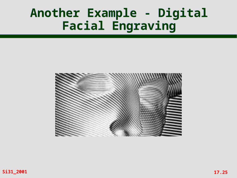
Another Example - Digital Facial Engraving
Another Example - Digital Facial Engraving

17.26Si31_2001
… and of course… and of course

17.27Si31_2001
Further ReadingFurther Reading
Papers by David Salesin, University of Washington
‘Expressive Rendering: A Review of Nonphotorealistic Techniques’, by John Lansdown and Simon Schofield, IEEE Computer Graphics and Applications, 1995.