170 conjan11
8
7/30/2019 170 conjan11 http://slidepdf.com/reader/full/170-conjan11 1/8 Composite materials are used increasingly in aircraft with demand increasing on a global scale but the rate of production is hampered by the speed at which the composites can be inspected during the manufacturing process. The four-year research project led by TWI Wales is designed to speed up the inspection process by 400% using advanced non-destructive testing technologies. IntACom (Improving the Inspectibility of Aerospace Composite Materials) which has had funding from the Welsh Assembly Government, involves an industrial collaboration with Rolls-Royce, GKN Aerospace and Bombardier Aerospace, with academic support from Swansea University, Swansea Metropolitan University and the University of Wales. Launching the project, Lesley Griffiths, Deputy Minister for Science, Innovation and Skills, said it had the potential to make a significant contribution to industry, specifically the aerospace sector. ‘It’s great news to hear that Wales is leading the way on the research and development of highly sophisticated technologies with the potential to make a significant impact on the production of composites. ‘I am par ticularly pleased the Welsh Assembly Government is supporting this research and that Wales is taking the lead and working with major players in the aerospace sector and benefiting from academic support from our Universities. ‘Our Economic Renewal strategy highlights the need to build upon the expertise that Aerospace sector to benefit from TWI-led industrial research collaboration Lesley Griffiths, Deputy Minister for Science, Innovation and Skills Issue 170 January/February 2011 Diary events March 2011 Joint Technical Group meeting Offshore Oil and Gas and Polymers Mon 14 Aberdeen Seminar Linear Friction Welding Thu 17 Great Abington Workshop and exhibition Meet the Buyer Thu 24 Stirling April 2011 Conference Association of Welding, Fabrication, Training and Education Fri 1 Great Abington Technical Group meeting Welding Processes Wed 13 Great Abington May 2011 Workshop Introduction to the UK Nuclear Industry Wed 4 May Stirling Conference Welding & Joining Society Wed 18 – Thu 19 Great Abington Workshops and seminars are recognised Continuous Professional Development events The magazine of TWI www.twi.co.uk e-mail:[email protected] A £3.8m industrial research collaboration announced on Wednesday 2 February is set to have a significant impact on the worldwide aerospace industry by speeding up the production of composite materials.
-
Upload
zubair-ahmed -
Category
Documents
-
view
224 -
download
0
Transcript of 170 conjan11

7/30/2019 170 conjan11
http://slidepdf.com/reader/full/170-conjan11 1/8
Composite materials are used increasingly
in aircraft with demand increasing on a
global scale but the rate of production
is hampered by the speed at which the
composites can be inspected during the
manufacturing process.
The four-year research project led by TWI Wales is designed to speed up the
inspection process by 400% using advanced
non-destructive testing technologies.
IntACom (Improving the Inspectibility
of Aerospace Composite Materials)
which has had funding from the Welsh
Assembly Government, involves an
industrial collaboration with Rolls-Royce,
GKN Aerospace and
Bombardier Aerospace,
with academic supportfrom Swansea University,
Swansea Metropolitan
University and the
University of Wales.
Launching the project,
Lesley Griffiths, Deputy
Minister for Science,
Innovation and Skills,
said it had the potential
to make a significant
contribution to industry, specifically the
aerospace sector.
‘It’s great news to hear that Wales is leading
the way on the research and development
of highly sophisticated technologies with
the potential to make a significant impact
on the production of composites.‘I am par ticularly pleased the Welsh
Assembly Government is suppor ting this
research and that Wales is taking the lead
and working with major players in the
aerospace sector and benefiting from
academic support from our Universities.
‘Our Economic Renewal strategy highlights
the need to build upon the expertise that
Aerospace sector to benefit
from TWI-led industrial
research collaboration
Lesley Griffiths, Deputy Minister for Science, Innovation and Skills
Issue 170 January/February 2011
Diary events
March 2011
Joint Technical GroupmeetingOffshore Oil and Gasand PolymersMon 14 Aberdeen
Seminar Linear Friction WeldingThu 17Great Abington
Workshop and exhibitionMeet the BuyerThu 24Stirling
April 2011
Conference
Association of Welding,Fabrication, Training andEducationFri 1Great Abington
Technical Group meetingWelding Processes
Wed 13Great Abington
May 2011
WorkshopIntroduction to the UKNuclear Industry
Wed 4 May Stirling
ConferenceWelding & Joining Society
Wed 18 – Thu 19Great Abington
Workshops and seminars
are recognised
Continuous ProfessionalDevelopment events
T h e m a g a z i n e o f T W I
w w w . t w i . c o . u k e - m a i l : t w i @ t w i . c o . u k
A £3.8m industrial research collaboration announced on Wednesday
2 February is set to have a significant impact on the worldwide aerospace
industry by speeding up the production of composite materials.

7/30/2019 170 conjan11
http://slidepdf.com/reader/full/170-conjan11 2/8
2
January/Fe bruary 2011
C on ne ct J an ua r y /F eb ru ar y 2 01 1 w w w . t w i . c o . u k e - m a i l : t w i @ t w i . c o . u k
exists within Welsh universities and businesses to harness
the commercial opportunities of innovation and research.
This is a good example of such collaboration between
the private and public sector and between industry and
academia.’
Philip Wallace, Regional Manager of TWI Wales, which is
based in ECM², Port Talbot, explained that the advancement
in composites had not been equally matched by an
advancement of inspection capability.
‘Composites inspection is a difficult and highly complex
area but is not yet sufficiently developed to meet industry
needs. The time it takes to carry out inspections at different
stages of the manufacturing process is actually hampering
and slowing down the entire process.
‘Our aim is to increase the process by 400% without losing
reliability or sensitivity and once we have developed the
inspection technology at the manufacturing level we will
further develop testing and inspection capabilities for in
service maintenance and repair.”
TWI NDT Validation Centre (Wales) was set up with
support from regional initiatives (through the Welsh
Assembly Government and Welsh European Funding
Ofce) to provide expertise in the area of advanced NDT,
complementing the facilities located at TWI’s headquarters
in Cambridge.
Activities at the Centre include development of advanced
inspection technologies, research into applications of
conventional and novel inspection methods and practical
inspection work.
Consultancy services, such as Level III support, trouble-
shooting, advice on applications and procedure
development/approval are also available from the Centre.
Validation of newly developed technologies and procedures
can be provided by the Validation Centre.
For more information, contact, [email protected]
continued from p.1
Alere Technologies LtdUK Medical device developmentand manufacture
Amey Area 9 Bridges TeamUK Maintenance of motorway structures in the Midlands
Autoliv IncSwedenManufacture and sale of occupant restraint systems
AVIC Beijing Institute of Aeronautical MaterialsChinaAircraft and aeroenginefabrication research
Brandon Medical Co Ltd
UK Design and manufacture of
medical lighting, power andcontrol systems and medicalaudio visual
CalegeoUK Marine surveying
Cavitar LtdFinlandDiode laser illumination/materials processing
Centrica Storage LtdUK Gas process/storage, on- andoffshore
CLP Power Hong KongLimited – GenerationBusinessHong Kong
Electricity generation
DatapaqUK Thermal process monitoring
Domino UK LtdUK Manufacture of ink jetprinting products and processdevelopment
Erlson Precision LtdUK Precision machining andassembly operations
Fife Council TransportationServices (Lighting)UK Local authority
Invibio LtdUK
Biomaterial manufacture
Mitsubishi Electric - Energyand Industrial Systems
JapanPower systems for rail, power and industry
Praxair Metal FabricationsGroup – GlobalUSAIndustrial gases
Reaction Engines LimitedUK Heat exchanger, spaceplaneand space propulsion design
Smith & Nephew – Wound ManagementUK
Wound care products
Victrex plc
UK Polymer production
New Members of TWITWI is pleased to welcome the following as Industrial Members

7/30/2019 170 conjan11
http://slidepdf.com/reader/full/170-conjan11 3/8
w w w . t w i . c o . u k e - m a i l : t w i @ t w i . c o . u k C on ne ct J an ua r y /F eb ru ar y 2 01 1
January/February 2011=
3
Nano-indentation at TWI
A nano-indentor system is a sophisticated alignment
assembly, a small load cell, a piezoelectric depth sensing
device, a sample holder and an indenter at 900 to the
sample holder. As the indenter is driven in and out
of a sample at constant load, its penetration depth is
continuously monitored. The resultant load-depth cur ve
gives the information needed to determine hardness,
elastic modulus and other material properties. Modern
instruments allow the user to glean useful and accurate
material property values with penetration depths as low as
a few nanometres.
Typical applications include:
• Mapping of surface properties across small areas(measurements may be taken down to 1µm apart)
• Elastic and plastic properties of materials at the nano-
scale
• Mechanical property measurement of individual phases
or grains
• Creep analysis
• Nano-scratch and wear testing; primarily for cohesive
and adhesive assessment of coatings
• Nano-indentation probes mechanical properties at high
strain rate, investigating surface fatigue and fracture due
to repetitive contact
• Testing under heated and cooled conditions (-30 to
750°C)
• Testing in liquid environments (eg biomedical and
corrosive environments)
These techniques provide more application specific material
property data which are complementary to the basicambient conditions test data and have allowed many users
to accurately simulate the results of larger scale, expensive
field testing in the laboratory environment.
Recently nano-indentation was used within two TWI
projects on dissimilar metal interfaces for subsea
applications and adhesion of transparent conductive oxides
on to different substrates. This information improves finite
element simulations for reliability prediction of joined
structures. These simulations are only useful industrially
when they are given the correct gradient of mechanical
properties across interfaces and related activation energiesif needed.
For further information on nano-indentation, or to request
trials, please contact [email protected]
Nano-indentation is a depth sensing indentation technique, which promises to become an important mechanical characterisation tool for precision components. By using a nano-indentor, which can
sample directly from the area of interest, engineers can begin to predict much more accurately how
their products will behave.
Typical failure modes of transparent conductive oxides deposited onto
different substrates: PEN, glass and Si.
Nano-indentation array across F65 / Alloy 625 dissimilar metal
interface: a) micrograph of cross section and indentation locations;
b) nano-hardness. Location of interface is indicated; and c) Elastic Modulus. Location of interface is indicated.

7/30/2019 170 conjan11
http://slidepdf.com/reader/full/170-conjan11 4/8
C on ne ct J an ua r y /F eb ru ar y 2 01 1 w w w . t w i . c o . u k e - m a i l : t w i @ t w i . c o . u k 4
Techn olog y Trans fer
Job Knowledge110 Welding of titanium and its alloys
Part 2
Titanium and its alloys are remarkably
resistant to the cracking problems
experienced by many of the other
alloy systems. Solidification and
liquation cracking are virtually
unknown and what could perhaps be
called cold cracking, occurs generally
only because of embrittlement arising
from contamination, as discussed in
Part 1.
Porosity is the commonest problem,
particularly when close square butt
joints are used. It is generally attributed
to hydrogen and cleanliness is
therefore crucial in eliminating porosity.
The porosity may be of one or a
mixture of two types: firstly micro-
porosity formed within the arms of
the dendrites during solidification andsecondly, larger pores that often align
themselves along the weld centreline.
As discussed in Part 1, cleanliness
is the key to defect-free welds and
this means that not only must the
component be thoroughly degreased
but so should the filler wires; weld
preparation edges must be deburred
and the highest purity shielding gas
must be used. Ideally the gas should
have a dew point of less than -50OC
(39ppm H2O) and to maintain this
low level the gas supply system should
be free of leaks. Regular and frequent
maintenance of the system is therefore
essential, checking the joints for leaks
and for damaged hoses. Ideally the
gas supply should be from a bulk gas
tank, not cylinders, and delivered to
the workstations via welded or brazed
steel or copper tubing. Plastic hoses
should be kept as short as possible;
most plastics used are porous and will
allow moisture to permeate through
the hose wall; neoprene and PVC
are the worst, Teflon one of the least
porous. It is worth remembering that
moisture can collect in the hose over a
period of time so a porosity problem,
after a weekend shut down, may be an
indication that this is occurring.
TIG filler wires should be cleaned
with a lint-free cloth and an efficient
degreasant immediately before use.
Following cleaning, the wire should not
be handled with bare hands but whilst
wearing clean, grease-free gloves. MIG
wire presents more of a problem but
devices to clean the wire as it passes
through the wire feeder are available.
For the best results wire that has beenshaved to remove any embedded
contaminants can be obtained.
A further potential source of
contamination that is frequently
overlooked is the use of air powered
tools for wire brushing or dressing
weld preparations and welds. Most
compressed air contains moisture
and oil so that, even when oil and
moisture traps are fitted, it is possible
to leave a thin film of moisture and/
or oil on the surface to be welded.
It is recommended that electrically
powered tools are used at all times
once the item has been degreased
prior to welding.
Although regarded as a very minor
problem, ductility dip cracking (where
alloys experience a severe loss of
ductility at a temperature below
the solidification temperature) has
been noted in some of the titanium
alloys; the alpha-beta alloys containing
niobium being the most susceptible
with Ti-6Al-2Nb-1Ta-0.8Mo the most
sensitive. The temperature range in
which this loss of ductility occurs
is between 750OC and 850OC.
The cracking is intergranular and is
thought to be partly the result of
volume changes during the beta to
alpha phase change coupled with the
reduction in ductility.
A significant amount of welding of
titanium alloys is carried out without
filler metals. When filler wire is used,
generally a composition matching that
of the parent metal is selected. There
are some exceptions: the welding
of high strength but low ductility commercial purity titanium is generally
performed with a low strength filler
metal to achieve the desired weld
quality. Similarly, unalloyed filler metal
is sometimes used to weld alloys such
as Ti-6Al-4V, thereby improving weld
metal ductility by lowering the amount
of beta phase that is formed. Extra low
interstitial (ELI) filler metals are also
available and may be used to improve
weld metal ductility and toughness.
Most of the titanium alloys can be
successfully fusion welded using the
gas shielded welding processes and
power beams; all can be welded
using solid phase processes, friction
and resistance welding. Welding
parameters and weld preparations are
similar to those that would be used to
weld a carbon steel. From the welder’s
point of view, titanium is easier to weld
than steel, having good fluidity and
7/30/2019 170 conjan11
http://slidepdf.com/reader/full/170-conjan11 5/8
w w w . t w i . c o . u k e - m a i l : t w i @ t w i . c o . u k C on ne ct J an ua r y /F eb ru ar y 2 01 1
Techn olog y Trans fer
5
high surface tension, easing the task of
depositing sound full penetration root
beads.
TIG welding is probably the most
commonly used process in bothmanual and mechanised applications.
The current is DC-ve, generally with
high purity argon as the shielding gas,
although helium or Ar/He mixtures
may be used to improve penetration.
Torch nozzles should be fitted with
gas lenses to improve gas shielding
and the ceramic shroud should be as
large a diameter as possible. A1.5mm
diameter tungsten, for example, should
be used with a 16mm diameter ceramic. Arc lengths need to be as
short as possible to reduce the risk
of contamination; 1 to 1.5 times the
electrode diameter is regarded as
a good rule of thumb. Arc initiation
should be achieved by the use of HF
current or lift arc to prevent tungsten
contamination. The equipment
must also be capable of continuing
the shield gas flow after the arc is
extinguished so that the weld cancool within the protective gas shield.
It is also advisable to keep the tip of
the filler wire within the gas shield
until such time as it has cooled to a
sufficiently low temperature.
A supplementary trailing gas shield will
also need to be attached to the torch
to provide protection to the cooling
weld metal as the welder moves along
the joint line. This makes manipulation
of the welding torch more difficult.
Most welders manufacture their own supplementary shields, shaped
to closely fit the component; several
shields would therefore be required
to weld a range of pipe diameters. A
backing gas is also necessary and back
purging should be maintained for at
least the first three or four passes in
a weld. Backing gas purity should be
better than 20ppm maximum oxygen.
MIG welding using argon or Ar/He mixtures may be used but this
process will not provide the same high
quality weld metal as the TIG process
and it can be difficult to achieve the
stringent quality levels required by
aerospace applications. Dip transfer
can lead to lack of fusion defects
and spray transfer requires both
leading and trailing supplementary
gas shields, the leading onr to prevent
oxidation of any spatter that may be remelted into the weld pool.
The improvements in pulsed MIG
power sources by the use of inverter
technology and microprocessor
control have obviated some of these
problems and substantially narrowed
the gap between MIG and TIG. MIG
is, however, still difficult for the manual
welder because of the difficulty of
manipulating the MIG torch with a
supplementary gas shroud. Because of
these difficulties MIG welding is oftenmechanised or automated.
Plasma-TIG may be used for welding
titanium, being capable of keyholing
a weld up to 12.5mm thickness. The
same requirements for gas purity and
weld pool protection required for
TIG are also needed for plasma-TIG.
Plasma-TIG is rarely used in a manual
application and never in the keyhole
mode.Atmospheric contamination is best
avoided by use of a welding chamber
or glove box that can be filled with
argon. Purpose built glove boxes
can be purchased but it is a simple
matter to fabricate a chamber of an
appropriate size using slotted angle
eg Dexion®, to form the frame
and covering this with a clear plastic
or acetate sheet. The size of the
component that can be welded withina glove box is necessarily restricted.
Electron beam, laser, friction, resistance
spot and seam and flash welding
are all used to weld titanium and its
alloys. Electron beam welding, being
carried out in a vacuum, needs no
protective gas shield. Conventional
friction welding may also be carried
out without a protective shield
although a gas shield should be usedwhen friction stir welding. Similarly,
no gas shield is required when
resistance welding, although for the
most critical applications a gas shield
is recommended. Laser and flash
welding both require gas shielding for
the best results and least atmospheric
contamination.
This article was written by Gene MathersCourtesy Huntingdon Fusion Techniques
7/30/2019 170 conjan11
http://slidepdf.com/reader/full/170-conjan11 6/8
C on ne ct J an ua r y /F eb ru ar y 2 01 1 w w w . t w i . c o . u k e - m a i l : t w i @ t w i . c o . u k 6
January/Fe bruary 2011
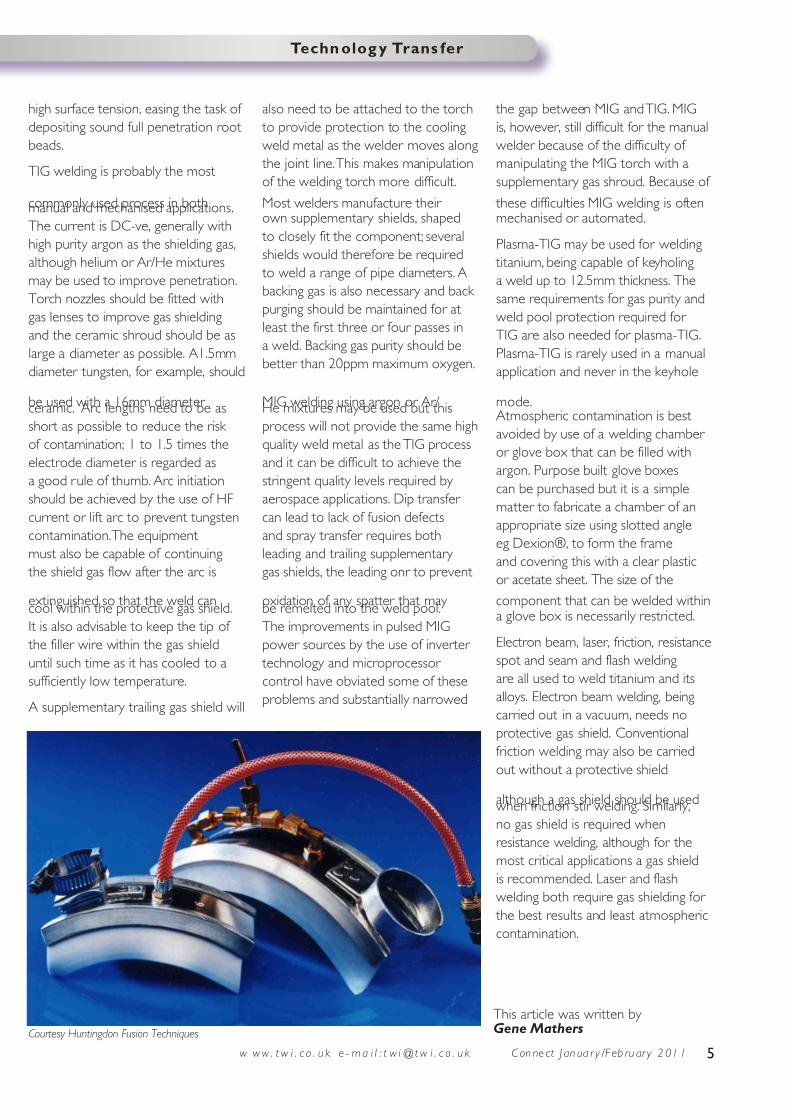
Skills gap training and certification
identified in the UK oil and gas industry
TWI Training & Examination Services has recently
conducted a skill analysis of the roles and duties
of the NDT/Rope Access Inspector employed
within the UK oil and gas sector. Its findings were
discussed with NDT contracting companies and
oil company representatives.
This study revealed that the average NDT/Rope Access
Inspector spent a high proportion of their time conducting
visual inspections of the plant rather than applying NDT
methods such as ultrasonic thickness gauging or corrosion
monitoring. However, the formal qualifications held were in
the applied NDT methods and little or no formal training
had been gained in visual inspection of the components
normally inspected.
It was also found that the Inspectors had received little or
no formal training regarding standard inspection processes
or familiarisation with the various types of drawings or
specific reporting processes to be used.
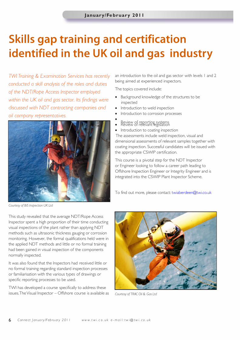
TWI has developed a course specifically to address these
issues. The Visual Inspector – Offshore course is available as
an introduction to the oil and gas sector with levels 1 and 2
being aimed at experienced inspectors.
The topics covered include:
• Background knowledge of the structures to be
inspected
• Introduction to weld inspection
• Introduction to corrosion processes
•
Review of reporting systems• Review of relevant legislation
• Introduction to coating inspection
The assessments include weld inspection, visual and
dimensional assessments of relevant samples together with
coating inspection. Successful candidates will be issued with
the appropriate CSWIP certification.
This course is a pivotal step for the NDT Inspector
or Engineer looking to follow a career path leading to
Offshore Inspection Engineer or Integrity Engineer and is
integrated into the CSWIP Plant Inspector Scheme.
To find out more, please contact: [email protected]
Courtesy of TRAC Oil & Gas Ltd
Courtesy of BIS Inspection UK Ltd

7/30/2019 170 conjan11
http://slidepdf.com/reader/full/170-conjan11 7/8
7w w w . t w i . c o . u k e - m a i l : t w i @ t w i . c o . u k C on ne ct J an ua r y /F eb r ua r y 2 01 1
January/February 2011
Shift-Ref Demonstration Day
Tuesday 8 March
TWI North, Middlesbrough
This half-day event offers an
opportunity to see the output from
the TSB project, Shift-Ref which has
developed a technique for electron
beam welding large components
without the need for a vacuum
chamber.
This event will provide an introduction
to the local vacuum EB process and
highlight its benefits and potential
applications. There will be an
opportunity to view the equipment
that has been designed and to
observe a demonstration of the
system.
Contact: [email protected]
Chris Eady joins Board of the
European Welding Federation (EWF)
At the General Assembly of the EWF,
Joining and Cutting, in Portugal,
Eur Ing Chris Eady, Chief Executive of
TWI Certification Ltd and Associate
Director for Professional Affairs at
The Welding Institute was appointed
to the Board of Directors. Chris said,
‘I am honoured to be elected to
the Board of EWF and I relish the
opportunity to contribute further
to the enhancement of welding
engineering skills for the benefit of
European industry.’
Danny Broadbent wins Silver in
EuroSkills Lisbon 2010
Danny Broadbent, SkillWeld 2010
Finalist, has taken a joint Silver
Medal in the EuroSkills 2010
welding competition in Lisbon. This
competition is designed to raise skills
standards, promote excellence and
increase awareness of the importance
of skills and vocational education and
training for the EU economies and
societies.
Danny entered the competition to
hone his skills in preparation for
WorldSkills 2011 and his excellent
performance bears testament to the
quality of welder training and skills in
the UK.
The Welding Institute is proud to
support the SkillWeld competition
and the development of welding
competitors for WorldSkills
London 2011.
News in brief
Subsea testing from ROVs
TWI has successfully completed a
collaborative project - SubCTest - to
develop novel NDT procedures and
equipment for deployment from
remote operating vehicles (ROVs)
on subsea offshore structures and
pipelines.
The project was carried out
by a consortium of small-to-
medium sized enterprises,
research organisations and
end-users and was supported
by a €1million grant from the
European Commission within
their Framework 7 funding
scheme.
The TWI-led consor tium
developed a range of novel
NDT techniques using phased
array ultrasonics, alternating current
field measurement (ACFM) and long
range ultrasonic testing (LRUT).
The equipment included a design of
phased array transducer for multi-skip
and creep wave ultrasonics, an ACFM
array probe that allows scanning
of complex node welded joints
in a single pass, a racetrack LRUT
technique for chains and an orbiting
focused LRUT technique for welds.
A robotic manipulator was successfully
demonstrated from an observation
class ROV and, simulations were used
to demonstrate performance when
used on an offshore jacket structure.
For more information on the project
or how TWI could help you with your
testing requirements, contact
Simulation of ROV deployment on ‘jacket’ legs

7/30/2019 170 conjan11
http://slidepdf.com/reader/full/170-conjan11 8/8
For further
information on
TWI
visit the website at
www.twi.co.uk
8
Connect is the
bi-monthly magazine
of TWIEditor:
Penny EdmundsonPhotography: Simon CondieProduction:
Penny Edmundson
© Copyright TWI Ltd 2011
Articles may be reprinted
with permission from
TWI. Storage in electronic
media is not permitted.
Articles in this publication
are for information only.
TWI does not accept
responsibility for the
consequences of actions
taken by others after
reading this information.
This publication is alsoavailable in alternativeformats. Please [email protected] to
request a copy.
Published byTWI Ltd, Granta Park,
Great Abington,
Cambridge CB21 6AL, UK
Tel: +44 (0)1223 899000
Fax: +44 (0)1223 892588
E-mail: [email protected]
www.twi.co.uk
TWI Technology Centre
(North East)
Tel: +44 (0)1642 216 320
Fax: +44 (0)1642 252 218
TWI Technology Centre
(Yorkshire)
Tel: +44 (0)114 269 9046
Fax: +44 (0)114 269 9781
TWI NDT Validation
Centre (Wales)
Tel: +44 (0)1639 873 100
Fax: +44 (0)1639 864 679
TWI Aberdeen
Tel: + 44(0)1224 691222
w w w . t w i . c o . u k e - m a i l : t w i @ t w i . c o . u k
Issue 170 January/February 2011
TWI hosts Chinese delegation
This is the second trade visit to TWI by a
high ranking Chinese Government official
in less than a month. In December 2010,UK Trade and Investment (UKTI) led a visit
by Chinese Minister Counsellor. Mr ZHOU
Xiaoming was so impressed with TWI,
and the company’s strong links with China,
that he advised this delegation to find
out for themselves the potential business
opportunities at TWI during their UK Trade
Mission.
Graham Wylde, TWI Associate Director
said: ‘We were delighted to be chosen by
the Chinese Embassy in London to host
part of the delegation’s Trade Mission tour
in the UK.
We have a long history of working with
Chinese companies, which goes back
twenty years. TWI staff spends more than
twenty weeks a year servicing their Chinese
customer base to maintain good relations
and look at future business opportunities.
Today has been extremely productive
and we have received positive feedback
from the delegation, with many companieskeen to meet again and explore how our
services could further benefit their future
business.
Working together with the UKTI and
Embassies abroad, in hosting events for
vitally important trade missions like these, is
a great opportunity for TWI.’
On Monday 10 January over 50 delegates from Chinese industrial
companies made a visit to TWI. The group was led by Mr SUN Guangbin,
Director, China Chamber of Commerce for Import and Export of
Machinery and Electronic Products.
Q
A JoinITregister nowwww.twi.co.uk
What is meant by single-pointmeasurement of fracture?
Where can I find informationregarding porosity in aluminium?
How do I select a consumablefor welding cast iron?