17. 2011 - ch.medical.canon
52
ISSN 1617-2876 TOSHIBA MEDICAL SYSTEMS JOURNAL 17 . 2011 Ultrasound 2D and 3D ultrasound capabilities X-Ray First Infinix VF-i/SP with 30 x 30 cm FPD installed in Europe MR Non-Contrast- Enhanced MRA by 3T MRI CT Aquilion PRIME, the world’s first 80-row CT scanner
Transcript of 17. 2011 - ch.medical.canon

ISSN 1617-2876
toshiba medical systems journal
17. 2011
Ultrasound2D and 3D ultrasound capabilities
X-RayFirst Infinix VF-i/SP with 30 x 30 cm FPD installed in Europe
MRNon-Contrast-Enhanced MRA by 3T MRI
CT Aquilion PRIME, the world’s first 80-row CT scanner

TOSH
IBA
MED
ICA
L SYSTE
MS
IMPRINT
Imprint
Publisher:TOSHIBA Medical
Systems Europe B.V.,Zilverstraat 1
NL-2718 RP ZoetermeerTel.: +31 79 368 92 22Fax: +31 79 368 94 44
Email: [email protected]
Web site at: www.toshiba-medical.eu
Editor-in-chief: Jack Hoogendoorn
Modality coordinators:CT: Roy Irwan
UL: Joerg Schlegel
Printing: Frotscher Druck,
Darmstadt
Subscription Service:Email: [email protected]
© 2011 by TOSHIBA Medical Systems Europe
All rights reserved
Aquilion PRIME, Toshiba‘s new 160-slice multislice
CT scanner incorporating the latest technologies
from the flagship Aquilion ONE scanner.
VISIONS 17 . 11

VISIONS 17 . 11 EDITORIAL
ED
ITO
RIA
L
Dear reader,
3
Toshiba’s business mission is to contribute to society through innovative healthcare solutions by developing advanced, value-added medical technologies, products and systems supported by excellent service.
Last year we celebrated the 80th anniversary of Toshiba’s medical business. During these 80 years, we have continued to reinvent ourselves, not only because we want to stay connected with you, but also because we embrace the idea of strengthening our bonds so that we can be sure to provide what you need tomorrow, as well as what you want today. This is the way we emphasize our commitment to partnering with you; our valued customers from all over the world.
It is my pleasure – as President and CEO of Toshiba Medical Systems Corporation – to present to you this new, exciting edition of VISIONS. As usual, you will find many articles about innovative products, advanced technologies and special applications, such as the Aquilion PRIME; the next generation 160-slice multi detector CT scanner and the latest addition to our Aquilion family. The system is equipped with key features, for example Adaptive Iterative Dose Reduction (AIDR) that lowers the noise level up to 50% and reduces the patient dose up to 75% compared to conventional scanners. Read about the world’s first installations in the Rode Kruis hospital in the Netherlands and Mount Elizabeth Hospital in Singapore.
The message is clear: Toshiba innovates! Even more – our innovations are environment-friendly, a fact which does not go unnoticed. We are proud to inform you that Toshiba Corporation ranks no. 10 in the most recent Newsweek list of the world’s greenest companies. A major achievement while we are happy to contribute to a sus-tainable society with our ECP and Excellent ECP products.
I hope that VISIONS magazine – and the online version – shows you today’s possibilities to further enhance the quality in clinical examinations and will inspire you in your daily practice as a medical professional.
I wish you a successful ECR 2011 which we hope, will include a visit to our booth #315 in Expo C.
Kind regards,
Satoshi TsunakawaPresident and Chief Executive OfficerToshiba Medical Systems Corporation

Aquilion PRIME - The world’s first 80-row CT scanner receives a warm welcome. Page 6
With helical CT entire organs can be scanned within a single breath-hold. Page 17
4
Editorial
R. Nanne, U. UmansIntroducing the Aquilion PRIME
D.L.T. BusscherAquilion Expansion in Medical Imaging
R. Irwan, C. Verlooij, R. Joemai, R. NanneAEC Comparison With and Without AIDR
R.M.S. JoemaiUltra Helical Scanning – Fast Acquisition of CT Images
J.H. Reid, J.T. Murchison, E.J.R.van BeekCT Perfusion Imaging: The Best of Both Worlds
A. van den BiezenbosEnhancing Options in Radiology - The Infinix VF-i/SP with 30 x 30 cm FPD
3
6
10
14
17
20
22
Computed Tomography
X-Ray
With the advent of wide area detector CT perfusion imaging has become a reality. Page 20
VISIONS 17 . 11 CONTENTS

Non-contrast-enhanced MRA utilizes the high SNR of 3T scanners and is becoming increasingly routine. Page 30
The first Infinix VF-i/SP with 30 x 30 cm FPD was installed in Europe. Page 22
VISIONS 17 . 11
5
Meanwhile at Toshiba
I. AokiNon-Contrast-Enhanced MRA by 3T MRI
B. SmithModern 3D Ultrasound Technology
in Gynaecology
L. Wilhelm2D Sonographic Evaluation
of Fetal Facial Clefts
26,43
30
34
44
Ultrasound
MRI
News
3D volumetric ultrasound is shown to be of tremendous value particularly in gynaecology and associated clinical areas. Page 34
CONTENTS
Visions: The Rode Kruis hospital in Beverwijk is the first in the world to install an Aquilion PRIME. What was
the reason to choose this system from Toshiba?Ulco Umans: We have enjoyed a long and con-
structive partnership with Toshiba which was key in our decision to purchase the Aquilion PRIME. Part-nership between hospitals and manufacturers that supply our equipment has become a far more critical factor in purchasing than it used to be, say ten years ago. Today we work together with suppliers, such as Toshiba, in two-way relationships, carrying out research projects with equipment and playing an important role in helping steer their innovations.
Our hospital is already equipped with several Toshiba systems, including our previous CT scanner, X-ray and ultrasound equipment. From these, we know that Toshiba systems are high quality, employ innovative, yet reliable technology and are supported with an outstanding service package for the life of the machines.
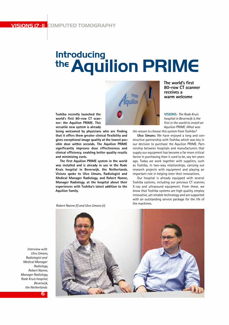
Toshiba recently launched the world’s first 80-row CT scan-ner: the Aquilion PRiME. This versatile new system is already being welcomed by physicians who are finding that it offers them greater clinical flexibility and gives exceptional image quality at the lowest pos-sible dose within seconds. The Aquilion PRiME significantly improves dose effectiveness and clinical efficiency, enabling better quality results and minimizing costs.
The first Aquilion PRiME system in the world was installed and is already in use in the Rode Kruis hospital in Beverwijk, the netherlands. Visions spoke to Ulco Umans, Radiologist and Medical Manager Radiology, and Robert nanne, Manager Radio logy, at the hospital about their experiences with Toshiba’s latest addition to the Aquilion family.
The world’s first 80-row CT scanner receives a warm welcome
Introducing the Aquilion PRIME
VISIONS 17 . 11 COMPUTED TOMOGRAPHY
6
Robert Nanne (l) and Ulco Umans (r)
Interview with Ulco Umans,
Radiologist and Medical Manager
Radiology,Robert Nanne,
Manager Radiology,Rode Kruis hospital,
Beverwijk, the Netherlands
We were looking to replace our CT system – a 4-slice Toshiba Asteion Multi - which was ten years old. Our medical imaging team of 20 technicians needed a system which could offer a greater range of op-tions so that they could broaden the scope of patient care offered here. The Aquilion PRIME allows us to perform a far wider range of routine and complex examinations efficiently, quickly and at low dose.
The Rode Kruis hospital is a relatively small facil-ity. We have 406 beds and space is very limited for equipping our diagnostic suite at this location. We cannot expand the space available and so have to rely on only one CT machine. Therefore it was vital that the system selected offered ultimate reliability.
What we really like about Toshiba’s equipment is that it is developed incrementally – building new innovation into a technology platform which is prov-en to be robust and reliable. This reassures us that any new product from Toshiba will be dependable, as well as technologically advanced. The Aquilion PRIME leverages the technology of the Aquilion ONE and is ideal for a wide range of examinations includ-ing sophisticated cardiac, body perfusion and dual energy examinations.
Robert nanne: I should add that we did indeed consider several other options with other vendors, but they simply couldn’t top the offer from Toshiba. The Aquilion PRIME represented the ultimate quan-tum leap in our progression. We actually feel quite honored to have the world’s first system here at Rode Kruis.
Visions: Could you describe the installation of the new system?
Ulco Umans: Toshiba’s installation team ensured that we were well prepared to receive the new sys-tem. They worked with us to explore every aspect of installation before a plan was agreed and imple-mented. Because of the age our hospital - it was founded in the early 1930s - and certain physical and operational features of the Aquilion PRIME, a number of important modifications to our CT room had to be made before installation could start.
Robert nanne: However, from start to finish, the installation took just three weeks, the first two weeks of which were needed to prepare the site. This is quite remarkable considering that the building preparations to accommodate the new machine are included.
In particular, the power requirements of the machine are higher than our previous machine and we had to adapt some older aspects of our hospital’s infra-structure to ensure that these could be met by laying some additional electrical cabling. We also had to ensure that the floor of the room could withstand the additional weight of the machine. We streng-thened the floor of the room after having consulted the Toshiba Site Planning group.
The actual installation of the system and its cali-bration took just four days. No time was wasted
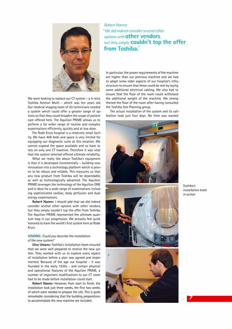
Toshiba’s installation team in action
7
Robert Nanne:“ We did indeed consider several other options with other vendors, but they simply couldn’t top the offer from Toshiba.”

Medical Center, I have been integrally involved in investigating the benefits of AIDR with this machine. To maximize AIDR’s dose saving effects Toshiba has integrated the AIDR technology into the Automatic Exposure Control package SUREExposure 3D. Less dose is needed to maintain high image quality at lower levels than ever before.
This is a particularly important development. Dose reduction is a key issue for continuous improvement of patient care in the healthcare industry, especially here in the Netherlands since we are a leading coun-try in continuous dose reduction.
Visions: Beyond dose reduction, what other kind of savings is the Aquilion PRIME helping you to achieve?
Ulco Umans: The performance, speed and ease of use of the system enable us to achieve large in-creases in throughput. We have already achieved a 25% reduction in the examination time for patients which has had a significant effect on improving pa-tient throughput. Aquilion PRIME has a large gantry
VISIONS 17 . 11 COMPUTED TOMOGRAPHY
8
- it was a question of out with the old and in with the new. To maintain the continuity of our services Toshiba offered a mobile system during the total period of installation. A perfect solution.
Ulco Umans: We were able to consult Toshiba’s expert team of technicians at any time on any is-sue. The accessibility and collaboration of staff was superb. Because this was the first Aquilion PRIME to be installed worldwide, there was a great deal of interest from Toshiba as well as from our own staff. We received a lot of VIP visitors from all over the world during the course of installation which added to the excitement of receiving the very first machine of its kind.
Visions: You have quite a large team of specialists. How was training organized?
Robert nanne: Training started even before in-stallation. We needed to ensure that all 4 staff using the machine were acquainted with it and comfort-able operating it as soon as possible to minimize any gap in service provision. The training was provided on an individual basis by Toshiba experts on site. Our specialists quickly picked up the techniques – the machine is easy to operate. Toshiba has put consid-erable thought into ensuring that the system is as user-friendly as possible.
Visions: What are the main clinical benefits offered by the system?
Ulco Umans: One of the biggest advantages is the fact that the system has broadened our scope of patient care. We now have the possibility to use the system for cardiac examinations for example. With the aid of Aquilion PRIME’s SURECardio software, we can quickly pick out and assess vascular images only at the click of a button.
Robert nanne: Dose reduction capabilities of the Aquilion PRIME are outstanding. Reductions of up to 70% have been achieved with the system using Adaptive Iterative Dose Reduction - AIDR. Together with experts from Toshiba and Leiden University
Aquilion PRIME, the world’s first 80-row CT scanner
Ulco Umans: “ The Aquilion PRIME allows
us to perform a far wider range of routine and complex
examinations efficiently, quickly
and at low dose.“

The Rode Kruis hospital in Beverwijk,the Netherlands
rotation speed, this energy is used for powering other components like couch and computers. With a hy-brid CT we as department can contribute to a better environment.
Visions: What is the service package from Toshiba like?
Ulco Umans: The service we have received from Toshiba over the years is far more than we expected. Service is available immediately on any issue and Toshiba’s service staff always have such a positive, can-do approach to problemsolving. This is a great reassurance since we will be using the machine for a long time. I know this is quite exceptional amongst vendors.
Visions: What else does the Aquilion PRIME bring to the hospital?
Ulco Umans: Working with cutting edge systems like the Aquilion PRIME makes radiology such an exciting field. Another side effect is that investing in such equipment helps us to attract the most highly skilled radiology staff and keep them! As you might understand this is vital in today’s competitive envi-ronment.
Robert nanne: The system is so advanced that it brings added value to our department. In the next seven years the hospital may be relocating but we will definitely be taking the Aquilion PRIME with us and based on Toshiba’s performance we may even consider purchasing additional systems from Toshiba for the new location.Visions: Thank you!
opening of 78 cm allowing fast and easy system set-up. Toshiba’s unique in-room scan control, called Handy Snap, allows us to instantly start scanning while closely observing the patient. This allows us
to improve patient care, especially for pediatric and trauma patients and benefits workflow so that we can examine more patients in a shorter space of time
Robert nanne: I should like to add that the Aq-uilion PRIME is an excellent example of Toshiba’s en-vironmental vision. Like the Aquilion ONE the PRIME gantry gains energy from slowing down the gantry
9
Robert Nanne: “ Dose reduction capabilities of the Aquilion PRIME are outstanding. Reductions of up to 70% have been achieved.”

time required for diagnosis. Aquilion PRIME incor-porates a variety of functions based on technologies that were developed for Aquilion ONE with the aim to significantly reduce patient dose, including Active Collimator, AIDR (Adaptive Iterative Dose Reduction), SUREExposure 3D and Boost3D.
AIDR uses an iterative algorithm to reduce image noise while maintaining details and structural edges. The patient dose can be significantly reduced with-out negatively affecting image quality.
From the first usersThe Rode Kruis hospital in Beverwijk in the Neth-
erlands is a medium-sized 406-bed facility which serves as teaching hospital for several disciplines. Located close to a steel industry area, the hospi-tal was the first institution in the Netherlands to establish a dedicated centre for burn victims and today is the national referral centre. Situated only 30 km west of the Dutch capital Amsterdam, the
IntroductionThe Aquilion PRIME, the new member of the
Aquilion family of CT scanners, opens up new pos-sibilities in medical imaging. The first PRIME was installed at the Rode Kruis hospital, Beverwijk, the Netherlands, several months before launch.
The Aquilion PRIMEThe Aquilion PRIME is a multislice helical CT
system with an 80-row detector capable of gene-rating 160 slices per non-helical rotation using the coneXactTM reconstruction algorithm. Unlike tech-niques such as flying focal spot this method to dou-ble the number of slices does not increase unneces-sary radiation exposure. With a consistent detector design of 0.5 mm, Aquilion PRIME covers up to 4 cm in the Z-axis.
High-speed rotation allows rapid data acquisition and shortens scan times, while the fast reconstruc-tion unit further improves throughput, reducing the
D.L.T. Busscher
Aquilion PRIME: Expansion in Medical Imaging
VISIONS 17 . 11 COMPUTED TOMOGRAPHY
10
The Aquilion PRIME with 80-row detector and 0.5 mm detector width covering up to 4 cm in the Z-axis
D.L.T. Busscher, MDRode Kruis hospital,
Beverwijk, the Netherlands

Fig. 2: CT scan of the thorax
displayed in coronal view
and 3D volume rendering
Rode Kruis hospital provides healthcare for 140,000 people in Beverwijk and the surrounding suburbs. The radiology department counts eight radiologists, 37 radiological technicians and eight administrative employees.
The Aquilion PRIME has been in full operation in Beverwijk since November 2010.
Dr. Umans (Radiologist and Medical Manager Radiology) and Robert Nanne (Manager Radiol-ogy): Since almost a decade there has been a good cooperation between our department and Toshiba. Our positive experience and thus satisfaction with Toshiba’s service of our angiographic equipment (Infinix) and multipurpose fluoroscopy unit (Ulti-max) and the low downtime of all the equipment have strengthened our trust in the company.
Our previous CT, the Toshiba Asteion Multi, a 4-row scanner, had served us for almost ten years and the time had come to replace it with a more up-to-date scanner. One of the requirements for the new scanner was that it be equipped with at least 64 detector rows. Our thoracic radiologists and car-diologists wanted to offer CT cardiography. With the old 4-row scanner we could handle approximately 25 scans during a working day. Since our staff is also in charge of emergency scans, it became increas-ingly difficult for them to fulfill all scan requests on time and with good quality. In addition, the Dutch government puts substantial pressure on healthcare 11
Fig.1: CT scan of the brain showing a large metastasis

VISIONS 17 . 10
12
COMPUTED TOMOGRAPHY
AcknowledgmentThe author wishes to thank John van Gulik and Jeroen Tijhaar for provid-ing the clinical images and Yvonne Hoogeveen for help with the prepa-ration of the manuscript.
providers to lower the radiation dose in all X-ray examinations. Therefore, we were very enthusiastic when Toshiba gave us the opportunity to be the first hospital worldwide to use their new Aquilion PRIME CT scanner.
One of the additional advantages of choosing a Toshiba scanner in our case was the graphic in-terface which is the same as that of the Asteion Multi. We were delighted to see that due to the short reconstruction time after only two months of using the PRIME our performance had increased to 40 scans during a 9-to-5 working day. It is a pleasure for radiologists and technicians alike to work on the post-processing station to produce magnificent re-constructions in 3D or MPR mode. The clinicians are very impressed by the information that can now be extracted from the reconstructed data.
First clinical resultsThe clinical images presented here were acquired
using low-dose clinical protocols with Adaptive It-erative Dose Reduction (AIDR).
The effective patient doses range from 1.5 mSv for thorax examination to 6 mSv for abdominal aorta examinations.
VISIONS 17 . 11
12
Fig. 3: CT scan of the abdominal aorta with stent
prostheses shown in curved
MPR and 3D volume rendering
Fig. 4: CT scan of the pelvis with metal screws in the hip
shown in coronal view and 3D volume
rendering

120 Sites - The number of Toshiba manufacturing sites worldwide that have environmental management systems in place.99,500 Tons - The amount of end-of-life products that were recycled by Toshiba Group worldwide in 2009.33 Tons - Amount per year Toshiba has reduced cardboard waste by reusing cardboard packaging for shipping CT couch covers.Toshiba’s current Aplio™ MX ultrasound system uses 30% less power than ultrasound systems manufactured in 2001.Toshiba’s current EXCELART Vantage™ MR system uses 35% less power than MR systems manufactured in 2001.Toshiba’s Aquilion® ONE CT system uses 75% less power than CT systems manufactured in 2001.Aquilion® ONE CT system power consumption can be regenerated. Energy is converted back into the system as electricity rather than heat to power the couch and gantry.In a newly constructed building in Japan, Toshiba has installed wastewater recycling, energy-saving lights and a rainwater harvesting system to help reduce Toshiba’s environmental footprint.Toshiba has been selected as a member of the Dow Jones Sustainability World Index for the 11th consecutive year since 2000.Toshiba is ranked #10 on Newsweek’s 2010 Green Rankings Global 100 list, the highest of all medical imaging vendors.Toshiba Medical Systems had it’s fi rst elaborate factory water treatment facility in the late 70’s!
The ECO style logo, which is intended to challenge the imagination, is formed of three circles that represent the three facets of our environmental management: Greening of Processes, Greening of Products, and Greening of Technologies.
Processes All activities of the company must be constantly reviewed for optimum performance. Apart from manufacturing, these are also processes such as freight, transport, heating of buildings, service activities, etc.
Products The key factor for our type of products is energy consumption. Solutions must be sought to reduce power requirements as much as possible. However, reduction of weight, use of alternative materials, omission of hazardous substances, possibilities such as “second Life“ are also part of this challenge.
Technologies Toshiba is active in the fi eld of Energy Technology which covers improved energy sources, battery effi ciency, bio cells or nuclear power.
ULTRASOUND CT MRI X-RAY SERVICES
www.toshiba-medical.eu
v2_Toshiba_advertentie_groen.indd 1 22-02-2011 15:24:32

as if they were acquired with standard exposure parameters. Furthermore, Automatic Exposure Control (AEC) systems on CT scanners have been a subject of great interest over the past years2-4. Therefore, in this paper, we describe a new phase of AIDR which is now integrated in the Toshiba AEC, SUREExposure 3D, which modulates the tube current in both xy- and z- directions. A thorough comparison of the physics of AECs from different manufacturers has been performed2.
The aim of our study is to demonstrate the behav-ior of AEC with and without AIDR and to evaluate the resulting dose reduction and image quality with the use of an anthropomorphic phantom.
Materials and methodsMaterialsThe anthropomorphic torso phantom (Fig. 2) was scanned with the 80-detector row MDCT scan-ner Aquilion PRIME located at Rode Kruis Hospital, Beverwijk, the Netherlands. This new scanner has a z-coverage of up to 4 cm and can generate 160 slices in one axial rotation with double slice mode as described in5. Unlike other techniques, such as flying focal spot, this method to double the number of slices does not produce unnecessary additional radiation.
IntroductionThere has been continuous progress in dose reduc-tion technologies across all major CT manufacturers, in particular in the field of iterative algorithms. The main goal, however, remains the same: to minimize the radiation dose according to the ALARA (As Low As Reasonably Achievable) principle.
Adaptive Iterative Dose Reduction (AIDR), de-scribed by Joemai1, is a sophisticated iterative algo-rithm which has been designed to work in both the raw data and reconstruction domains (Fig. 1). The collective AIDR process results in robust noise reduc-tion which is essential for achieving ultra low dose examinations for routine clinical imaging.
Lowering the X-ray exposure and therefore re-ducing the number of photons reaching the detector results in a decrease in signal-to-noise ratio in raw data. The AIDR algorithm first analyses the noise in the raw data and then adaptively applies noise correction based on the photon count. This process, in effect, increases the signal-to-noise ratio, particu-larly with low-dose acquisitions.
After raw data noise correction is applied, a primary reconstruction is performed. AIDR uses an iterative data enhancement algorithm in the recon-struction domain. This algorithm adapts to different organs which maximizes the noise reduction without compromising spatial resolution.
The final process involves a weighted blending of the iterative and the primary reconstruction to create the AIDR image. As a result of this blend-ing, the AIDR images retain a natural appearance
R. Irwan1, C. Verlooij1, R. Joemai2, R. Nanne3
AEC Comparison With and Without Iterative Dose Reduction Technique: a Phantom Study
VISIONS 17 . 11 COMPUTED TOMOGRAPHY
14
Fig. 1: Schematic diagram of Adaptive Iterative Dose Reduction (AIDR) which includes both raw
data and reconstruction domains to reduce the dose while maintaining best possible image quality.
1Toshiba Medical Systems Europe,
Zoetermeer2Leiden University
Medical Center, Leiden3Rode Kruis Hospital,
Beverwijk
Robert Nanne
Roy Irwan

Figure 3b: Measured SD along the phantom: with AIDR non-activated (blue) and with AIDR activated (red)
We performed two tests with SUREExposure 3D ac-tivated using Standard Deviation (SD) = 5 and with AIDR being activated as well as non-activated. The lower and upper tube current limits were set for both tests to 80 and 500, respectively.
Details of the radiation dose were obtained for each CT scan from the dose record. From the DLP values it was possible to estimate the variation in radiation dose by calculating the difference of the DLP with AIDR relative to the DLP without AIDR:
where the mean mA was used in both DLP calculations.To assess the image quality, the image noise was
compared in images obtained from scans performed with and without AIDR activated. Image noise is measured by placing regions of interest (ROIs) and looking at the SD of the fluctuations in CT-numbers. The ROIs were placed in a soft tissue simulating ma-
Furthermore, an active collimator is available in this scanner to minimize over-radiation by the heli-cal pre- and post-acquisition ranges. This active col-limator is controlled by slits which open and close at the beginning and end of each helical scan. The dose reduction is up to 20% depending on the scan range.
The phantom is 100 cm long with anatomical structures allowing various CT imaging techniques including helical scanning. It contains synthetic bones, brain with cerebral ventricles, lungs with pulmonary vessels, and many other specific types of organs are embedded. Each individual organ has particular Hounsfield Units corresponding to that of the human body6.
MethodsDuring CT acquisitions the phantom was centered according to a clinical routine CT examination, i.e. supine position, sagittal midline, and at the isocenter of the gantry (Fig. 1b). This position was to ensure reproducible image quality and optimum perform-ance of SUREExposure 3D resulting in minimal dose. The scanning direction was head first. The scan and reconstruction protocols are summarized in Table 1.
Tube Voltage [kV] 120Tube Current [mA] modulatedRotation Time [s] 0.5Collimation 80 × 0.5 mmFOV [mm] 320Matrix 512 × 512Pitch 0.8Reconstruction Kernel FC12
Fig. 2: Anthropomorphic phantom closely resembling a real human body6
Figure 3a: mA values along the phantom measured with non-activated AIDR (blue) and activated AIDR (red).
15Table 1: Scan and reconstruction parameters on Aquilion PRIME
dose reduction = DLP-DLPAIDR x 100% DLP
0
50
100
150
200
250
300
350
400
450
500
1 21 41 61
Tube Curr
ent (mA)
Slice Number
No AIDR AIDR
0
1
2
3
4
5
6
7
8
1 21 41 61
Noise (SD
of HU)
Slice Number
No AIDR AIDR
0
50
100
150
200
250
300
350
400
450
500
1 21 41 61
Tube Curr
ent (mA)
Slice Number
No AIDR AIDR
0
1
2
3
4
5
6
7
8
1 21 41 61
Noise (SD
of HU)
Slice Number
No AIDR AIDR

ment confirms the functionality of the integration of AIDR into SUREExposure 3D, which can be used in clinical routines for any exams. In clinical exams the degree of dose reduction will vary due to the adaptive nature of the AIDR algorithm. Typically, the degree of dose reduction ranges from 67–73%.
Finally, we conclude that iterative algorithms have opened up new possibilities for clinical CT ap-plications such as perfusion studies, both with tem-poral uniformity and minimized patient dose, reduc-ing a possible dose penalty.
AcknowledgmentsWe thank Toshiba Medical Systems Corporation, Japan, for providing Fig. 1 and peer-reviewing this paper and Henk de Vries for his constructive feed-back.
References1 Joemai R, “Improved Image Quality in Clinical CT by AIDR”, Toshiba
Medical Systems Journal VISIONS, Vol. 16, 20102 Söderberg M, “Automatic Exposure Control in CT: an investigation
between different manufacturers considering radiation dose and image quality”, MSc. Thesis, Lund University 2008
3 Imaging Performance Assessment of CT Scanners (IMPACT), http://www.impactscan.org/
4 McCollough CH, Bruesewitz MR, Kofler JM, Jr., “CT dose reduc-tion and dose management tools: overview of available options”, Radiographics 26:503-512, 2006
5 Blobel J, de Vries H, Irwan R, Mews J, Ogawa Y, “640 Multislice re-construction with dynamic volume CT”, Toshiba Medical Systems Journal VISIONS, Vol. 13, 2009
6 http://www.kyotokagaku.com/products/detail03/ph-4.html
terial of the phantom, and finally from each slice the median noise value was stored. The higher SD value, the more image noise is present.
ResultsFigure 3a shows the mA values per slice without (blue) and with (red) AIDR. Image quality (SD) was also measured per slice and is displayed in Fig. 3b.
In terms of subjective method to assess the im-age quality, we present in Figs. 4a and 4b to visually compare two reconstruction methods. Small objects (red arrows) have obviously been preserved while the noise is reduced at lower mA.
The dose reduction is calculated according to Eq. (1) above with DLP of 464 mGy*cm without AIDR and DLP of 135 mGy*cm with AIDR activated, result-ing in:
The dose reduction reported in this phantom study agrees well with that of a clinical study reported earlier in1.
ConclusionThere are many possibilities to attain significant dose reduction. We have presented AIDR which has been integrated into SUREExposure 3D. The results demon-strated that low-dose AIDR images were comparable to standard dose images for which AIDR was non-activated in terms of SD and visual assessment.
Dose reduction of more than 70% was achieved while maintaining highest image quality possible us-ing Automatic Exposure Control, which agrees well with the clinical study reported earlier. This agree-
VISIONS 17 . 11 COMPUTED TOMOGRAPHY
16
Figure 4a: Reconstruction with AIDR non-activated
Figure 4b: Reconstruction with AIDR activated. The SD was set to 5 for the mA modulation in both scans. Red arrows indicate preservation of small objects.
dose reduction = 464 –135 x 100% = 71% 464

17
VISIONS 17 . 11CoMPuTED ToMogRAPhY
In 2007, Toshiba introduced the Aquilion ONETM sys-tem which allows for volumetric scanning. The volu-metric 320-detector row CT scanner has a coverage of 160 mm and can be used to scan entire organs within one axial acquisition that takes 0.35 s. There are two options for scanning a larger range than 160 mm with the Aquilion ONE: 1 - wide volume acquisition, 2 - helical acquisition.
Helical scanning can be performed with acquisi-tion configurations of 64 x 0.5, 100 x 0.5 and 160 x 0.5 mm (number of active detector row times scanned slice thickness). The last two are known as ultra-helical acquisition configurations.
Helical CT is still generally applied in clinical practice with rotation times of about 0.35 s and a scanned slice thickness of 0.5 mm. Scanning a region of 1400 mm would take with a 4, 16, 64 and 160 detector row CT scanner at equal pitch 350, 88, 22 and 9 seconds respectively (Fig. 1).
IntroductionSince the introduction of clinical CT great improve-ments in scan time, patient comfort and resolution have been made. The first clinical CT scanner dates from 1972 and was developed by Godfrey Houns-field. It required an acquisition time of 5 minutes and reconstruction of one image took 7 minutes1. In the following years CT systems improved rapidly and by 1976 acquisition time for one CT image had decreased to 5 seconds with a reconstruction time of 40 seconds2.
Scanning entire body parts was still difficult at that time due to the long scan time, and image qual-ity was limited by the thick slices of the traditional CT systems. Helical CT scanning was realized by in-troducing continuous table motion during the scan. Helical acquisitions improved the performance of traditional CT by offering larger coverage and better 3D image quality. With helical CT entire organs can be scanned within a single breath-hold.
R.M.S. Joemai
ultra helical Scanning – Fast Acquisition of CT Images
Fig. 1: Illustration of 64 x 0.5 mm and 160 x 0.5 mm scanning. With ultra-helical (left) the same region can be scanned with fewer rotations and less time.
9 seconds 22 seconds
64x0.5 mm 160x0.5 mm
R.M.S. JoemaiLeiden University Medical CenterThe Netherlands
Raoul M.S. Joemai

VISIONS 17 . 11 COMPUTED TOMOGRAPHY
18
to develop the ultra helical acquisition techniques. Purpose of this study was to compare radiation
dose of standard helical scanning with ultra helical scanning and to demonstrate the performance of ultra helical acquisitions with a clinical case.
Materials and methodsAcquisition protocolAcquisitions were performed on the Aquilion ONE CT scanner (Toshiba Medical Systems, Nasu, Japan) at three helical acquisition configurations: 64 x 0.5 mm (normal helical), 100 x 0.5 mm (ultra-helical 1), 160x0.5 mm (ultra-helical 2). The imaged scan rang-es were 200, 400 and 600 mm for each acquisition configuration. Acquisition protocols were the same as those used in clinical practice, and the effec-tive tube current (mAs per slice) was kept constant for each acquisition. The acquisition parameters are shown in Table 1.
Overranging is a well known phenomenon in heli-cal CT and originally caused some unnecessary radiation exposure, particularly when acquisition configurations were used with a wide acquisition collimation and high numbers of active detector rows. The excessive radiation exposure that resulted from overranging limited the development of helical scanning using more than 64 active detector rows. Therefore a helical acquisition with for example 160 x 0.5 mm was previously undesirable.
To overcome this issue, the Toshiba Aquilion ONE CT scanner is equipped with an active collimator which eliminates unnecessary radiation exposure caused by overranging in helical acquisitions. The active collimator optimizes the collimation width during the acquisition; starting and finalizing the scan with a closed collimator and at optimized col-limation width during the scan. With the implemen-tation of the active collimator it became possible
Fig. 2: Scan time
of three scan lengths at
normal and ultra-helical
Table 1:Acquisitionparameters
Fig. 3: Measured
dose during acquisitions at different
scan lengths and acquisition
collimations
Acquisition Tube Voltage FOV Rot Time Tube Current Eff mAs Pitch Collimation (mm) (kV) (mm) (s) (mA)
64 x 0.5 120 400 (L) 0.5 200 121 0.83100 x 0.5 120 400 (L) 0.5 250 121 1.03160 x 0.5 120 400 (L) 0.5 240 121 0.99
0
2
4
6
8
10
12
14
Scan
�m
e (s
)
Scan Range 200mm Scan Range 400mm Scan Range 600mm
64x0.5mm
100x0.5mm
160x0.5mm
0
20
40
60
80
100
120
140
160
180
200
Dos
e fr
ee-i
n-ai
r (m
Gy)
Scan Range 200mm Scan Range 400mm Scan Range 600mm
64x0.5mm
100x0.5mm
160x0.5mm

19
Fig. 4: Application of ultra helical in clinical practice. This scan was performed within 5 sec-onds using an ultra helical acquisition Clinical case
Fig. 4 shows a scan of a patient which was used as reference for the initial condition before treatment by chemotherapy. The scan was performed from the shoulders to the pelvis with a scan length of 680 mm. Acquisition collimation was 160 x 0.5 mm at a scanning Field of View of 400 mm and the scan time was less than 5 seconds.
ConclusionUltra-helical scanning with 160 x 0.5 mm is now an attractive option since whole body scanning of trauma patients can be performed in less time compared to helical acquisitions. But also CT angio- graphy scans can be performed with the same image resolution but less contrast injection and with minimized patient motion.
Results have shown that measured dose for 160 x 0.5 mm ultra-helical is similar to 64 x 0.5 mm helical scanning. Also for small scan lengths, similar radiation dose was observed for ultra-helical.
Previously, the only possibility to minimize over-ranging was by selecting a smaller acquisition col-limation and a low pitch. Now, with the active col-limator, overranging is no longer a limiting factor for helical CT scanning. Fast scanning with acquisition collimation of 160 x 0.5 mm can be performed at optimized radiation exposure to patients.
References1 Data sheet EMI scanner, EMI, 1972 2 Data sheet Pho/Trax 4000, Searle, 19763 van der Molen AJ, Geleijns J. Overranging in multisection CT: quan-
tification and relative contribution to dose- comparison of four 16- section CT scanners. Radiology. 2007 Jan;242(1):208-16.
Dose measurementsDose measurements were made free-in-air with a 102 mm pencil ionization chamber (model CP-4C; Capintec, Ramsey, NJ) connected to a dosimeter (model 35050A; Keithley Instruments, Cleveland, Ohio). The ionization chamber was fixed to a sup-porting stand that was positioned on the floor. The ionization chamber was aligned along the central axis of the scanner so that the axis of rotation of the scanner coincided with the center of the ionization chamber. Dose measurements were similar as those described in the paper by Van der Molen et al.3.
ResultsDifferences in scan time for these three acquisition configurations are provided in Fig. 2 which shows that the scan time decreased substantially for the ultra-helical acquisitions, it decreased with 64% using 160 x 0.5 mm compared to 64 x 0.5 mm at a scan length of 600 mm. Ultra-helical acquisitions provide coverage of entire body parts within a few seconds. The dose free-in-air increases as expected for longer scan lengths but the effect of overranging, which is predominantly expected for ultra helical acquisitions, was not observed in the measurement results. This indicates excellent performance of the active collimator. Moreover, dose measurements showed similar dose levels for acquisitions using ultra-helical acquisition collimations (Fig. 3).
subjects was demonstrated in a study requiring cen-tral line injection and with limited z-axis coverage6.
Another recent application, using dual energy CT perfusion methodology, has been applied to the in vivo diagnosis of ground glass opacification and pulmonary embolism (PE)7-10. In the latter study, dual-energy CT was employed to detect and quan-tify perfusion defects, obstruction score and RV/LV ratio in acute pulmonary embolism in a single scan volume without the need for subtraction techniques which are prone to motion misregistration artefacts. Using dual energy this is possible by employing the material decomposition theory11. In this paper, we show that perfusion imaging can be considered as an excellent alternative diagnostic tool to dual energy.
It is well recognised that conventional CT pul-monary angiographic (CTPA) follow-up will under-estimate the presence, size and significance of per-fusion abnormalities as a cause for thromboembolic pulmonary hypertension. In the past, this diagnosis required scintigraphy as an additional test to provide this perfusion data12.
IntroductionA few years ago, the idea of combining the spatial
and temporal accuracy of CT with the recognised benefits of mapping regional perfusion for routine diagnosis was a dream. With the advent of wide-area detector CT that dream has become a reality.
The idea of assessing physiological phenomena using CT perfusion is not a new one with Leon Axel proposing a method for measuring cerebral blood flow just 8 years after Hounsfield introduced the first CT1. Because of technological limitations early attempts were largely confined to research studies of the brain and kidneys2. The introduction firstly of spiral and then multislice scanners has enabled assessment of perfusion in increasing volumes of tissue.
In the era of cerebral thrombolysis for acute cer-ebral ischaemia, perfusion imaging is gaining further impetus3,4. In this clinical setting, CT perfusion can provide crucial additional information to the stan-dard brain scan and CT cerebral angiogram. The 16 cm detector of the Aquilion ONE provides suffi-cient coverage in a single rotation for many selected organs in addition to the brain, such as heart and kidneys, but also for a significant portion of organs, including the liver and pulmonary circulation.
CT lung perfusion imaging has in the past been proven in various research models5. Most recently, the power of CT lung perfusion imaging in early de-tection and quantification of lung diseases in human
J.H. Reid, J.T. Murchison, E. J.R. van Beek
CT Perfusion Imaging: The Best of Both Worlds
VISIONS 17 . 11 COMPUTED TOMOGRAPHY
20
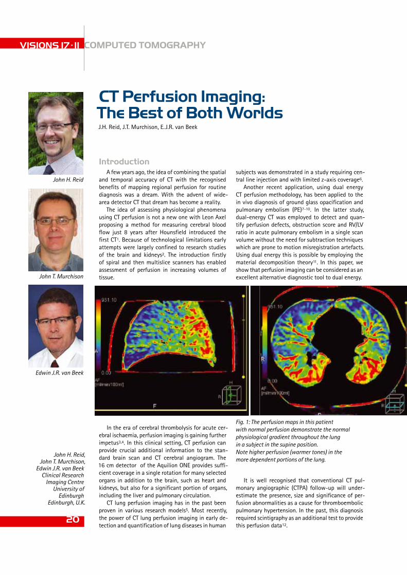
Fig. 1: The perfusion maps in this patient with normal perfusion demonstrate the normal physiological gradient throughout the lung in a subject in the supine position. Note higher perfusion (warmer tones) in the more dependent portions of the lung.
John H. Reid, John T. Murchison,
Edwin J.R. van BeekClinical Research
Imaging CentreUniversity of
EdinburghEdinburgh, U.K.
Edwin J.R. van Beek
John H. Reid
John T. Murchison

the gravity-dependent effects on the perfusion, but at the same time shows peripheral perfusion defects. The same study was evaluated for the presence of pulmonary embolism, which could not be demon-strated down to sub-segmental level. Based on this observation, it would appear that microvascular dis-ease causes persistent perfusion abnormalities, and this could be a sign for the future development of long-term complications, such as chronic throm-boembolic pulmonary hypertension.
ConclusionCT perfusion utilising wide-area coverage has the
potential to study physiological effects of lung and pulmonary vascular diseases. This work is to be ex-panded in the near future.
References1 Axel L. Cerebral blood flow determination by rapid-sequence com-
puted tomography: theoretical analysis. Radiology 1980;137:679–86.
2 Jaschke W, Sievers RS, Lipton MJ, Cogan MG. Cine-computed to-mographic assessment of regional renal blood flow. Acta Radiol 1990;31:77–81.
3 Mayer TE, Hamann GF, Baranczyk J, Rosengarten B, Klotz E, Wies-mann M, et al. Dynamic CT perfusion imaging of acute stroke. Am J Neuroradiol 2000;21:1441–9.
4 Konstas AA, Goldmakher GV, Lee TY, Lev MH. Theoretic basis and technical implications of CT perfusion in acute ischemic stroke, part 2: technical implementations. Am J Neuroradiol 2009;30:885-892.
5 Screaton NJ, Coxson HO, Kalloger SE, et al. Detection of lung per-fusion abnormalities using computed tomography in a porcine model of pulmonary embolism. J Thorac Imaging 2003; 18:14 –20.
6 Alford SK, van Beek EJR, McLennan G, Hoffman EA. Heterogeneity of pulmonary perfusion as a mechanistic image-based phenotyps in emphysema susceptible smokers. Proc Nat Acad Sciences (NY) 2010;107:7485-7490.
7 Pontana F, Remy-Jardin M, Duhamel A, Faivre J-P, Wallaert B, Remy J. Lung perfusion with dual energy multidetector row CT: Can it help recognize ground glass opacities of vascular origin? Acad Radiol 2010;17:587-594.
8 Thieme SF, Becker CR, Hacker M, Nikolaou K, Reiser MF, Johnson TR. Dual energy CT for the assessment of lung perfusion–correlation to scintigraphy. Eur J Radiol 2008;68: 369–374 .
9 Hoey ET, Gopalan D, Ganesh V, et al. Dual-energy CT pulmonary angiography: a novel technique for assessing acute and chronic pulmonary thromboembolism. Clin Radiol 2009;64 : 414–419 .
10 Chae EJ, Seo JB, Jang YM, Krauss B, Lee CW, Lee HJ, Song K-S. Dual-energy CT for assessment of the severity of acute pulmonary embolism: Pulmonary perfusion defect score compared with CT an-giographic obstruction score and right ventricular/left ventricular diameter ratio. AJR 2010;194:604-610.
11 Johnson TR, Krauss B, Sedlmair M, et al. Material differentiation by dual energy CT: initial experience. Eur Radiol 2007; 17:1510–1517
12 Tunariu N,Gibbs SJR, Win Z, Gin-Sing W, Graham A, Gishen P, AL-Nahhas A. Ventilation-perfusion scintigraphy is more sensitive than multidetector CTPA in detecting chronic thromboembolic pulmo-nary disease as a treatable cause of pulmonary hypertension. J Nucl Med 2007;48:680-684.
It is in the scenario of pulmonary embolism fol-low-up that our institution has initially explored the possibility of utilising the 16 cm z-axis coverage offered by Toshiba’s Aquilion ONE to provide novel functional perfusion data and at the same time pro-vide anatomical data on presence of residual thrombi.
TechniqueThe CT perfusion technique uses a peripheral in-
travenous injection of 70 ml of iodinated contrast (Iomeron 400 mg I/ml, Bracco) followed by 30 ml saline flush at the same injection rate.
The scan range is set to 160 mm using intermit-tent dynamic volume acquisition with a low dose protocol of 100 kV, 100 mA, a 400 mm field of view and a rotation time of 0.5 s. Scans are obtained from 5 s to 20 s after start of injection at 2 s intervals.
This method is capable of yielding low-dose CT pulmonary angiography data in addition to provid-ing the dynamic data required to obtain perform perfusion analysis.
Initial resultsFigure 1 shows a patient referred for possible
hepato-pulmonary syndrome. The images clearly demonstrate the gravity-dependent perfusion as expected in a normal distribution pattern. The lung has relatively homogeneous perfusion in the non-dependent areas.
Figure 2 shows a patient who was evaluated three months after a large central pulmonary thromboem-bolic event. This patient was still on oral anticoagu-lant therapy, but did not receive fibrinolytic therapy at the initial event. The study again demonstrates
21
Fig. 2: This patient, who previously sustained a massive pulmonary embolism, remained symp-tomatic 3 months after the inital event. Despite an apparently normal conventional CT pulmonary angiogram, there are areas of strikingly reduced perfusion in the infero-posterior regions of the lungs. Some of these areas demonstrate segmental distri-bution and are likely to represent chronic post-thrombotic occlusion.

In response to the continual and rapid devel-opment of cardiac and vascular care Toshiba launched its latest vascular imaging system in March last year - the Infinix VF-i/SP Shared Cardiac and Vascular Lab with 30 x 30 cm Flat Panel Detector (FPD) and extra small FPD housing. Since then, radiologists, vascular surgeons and cardiologists from all over Europe have welcomed the enhanced versatility and superior image qual-ity offered by the system. Global orders for the new Infinix VF-i/SP with 30 x 30 cm FPD have already topped 60 units.
Dr. Anton van den Biezenbos is a radiologist at Gelre Hospital in Zutphen, the Netherlands, where the very first Infinix VF-i/SP with 30 x 30 cm FPD sold in Europe, was installed in October 2010. He told VISIONS how the new system is ena-bling Gelre’s specialists to perform a wider range of procedures with greater ease and increased efficiency.
VISIONS: Could you tell us about Gelre Hospital?
Dr. van den Biezenbos: Gelre Hospitals is actu-ally a group of hospitals and clinics that operate together to serve the towns of Zutphen, Apeldoorn, Epe and Lochem in Gelderland, the biggest province of the Netherlands. The group has a total capacity of 925-beds. It includes the facilities of Gelre Hospital in Zutphen, which offers a wide range of clinical services. I have been working as a radiologist at the Gelre Hospital group for 11 years.
Gelre Hospital in Zutphen now operates from a brand new building which was opened in October 2010. The new facility features a state-of-the-art Cath Lab that enables us to provide increased op-tions for diagnostics and interventional procedures. One of the most advanced appliances acquired for the facility is the new Toshiba Infinix VF-i/SP with 30 x 30 cm FPD that was installed in the autumn of 2010 and was ready for use with the opening of the new building.
First Toshiba Infinix VF-i/SP 30 x 30 cm Flat Panel Detector
installed in Europe
Enhancing Options
in Radiology
VISIONS 17 . 11 X-RAY
22

Toshiba’s Infinix VF-i/SP in the angio intervention lab at GelreHospital, Zutphen
23
Dr. Anton van den Biezenbos:“ The system is outstandingfor interventional work. The image quality in particular brings great benefits here”.

Digital Subtracted Angiography and high
quality fluoroscopyimaging with Toshiba’s
Infinix-i-series.
The control room of Toshiba’s Infinix VF-i/SP
interventionalangiography system
at Gelre Hospital, Zutphen
resolution images also sounded superb for other di-agnostic and intervention procedures.
We needed a system which could offer excellent results across a wide range of disciplines, coupled with optimal reliability and affordability. The facili-ties of the new Cath Lab at Zutphen are designed for use by both the Intensive and Coronary Care Units. Radiologists, cardiologists and the pain management group all share use of the equipment. We immedi-ately recognized that the Infinix VF-i/SP with 30 x 30 cm FPD could meet the diverse needs of the whole medical imaging team here and enable us to offer a
VISIONS 17 . 11 X-RAY
24
VISIONS: Why did you choose Toshiba’s Infinix VF-i/SP Shared Cardiac and Vascular Lab with 30 x 30 cm FPD?
Dr. van den Biezenbos: The system was actually introduced to me by my colleagues in cardiology who were very enthusiastic about its specifications and the excellent service offered by Toshiba. Its 30 x 30cm FPD and extra small FPD housing enable the steep angulations required in many examina-tions performed in cardiac imaging. Its detector size, its maneuverability and its ability to produce high
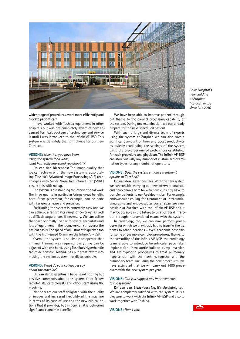
Gelre Hospital’s new building at Zutphen has been in use since late 2010
We have been able to improve patient through-put thanks to the parallel processing capability of the system. During one examination, we can already prepare for the next scheduled patient.
With such a large and diverse team of experts using the system at Zutphen we can also save a significant amount of time and boost productivity by quickly readjusting the settings of the system, using the pre-programmed preferences established for each procedure and physician. The Infinix VF-i/SP can store virtually any number of customized exami-nation types for any number of operators.
VISIONS: Does the system enhance treatment options at Zutphen?
Dr. van den Biezenbos: Yes. With the new system we can consider carrying out new interventional vas-cular procedures here for which we currently have to transfer patients to our Apeldoorn site. For example, endovascular coiling for treatment of intracranial aneurysms and endovascular aorta repair are now possible at Zutphen with the Infinix VF-i/SP and it may be possible in the future to treat cerebral infarc-tion through interventional means with the system.
In cardiology, too, we can now perform proce-dures for which we previously had to transfer the pa-tients to other locations – even academic hospitals for some of the more complex procedures. Thanks to the versatility of the Infinix VF-i/SP, the cardiology team is able to introduce biventricular pacemaker implantation, intra-aortic balloon pump insertion and are exploring procedures to treat pulmonary hypertension with the machine, together with the pulmonary team. Including the new procedures, we have estimated that we will carry out 1400 proce-dures with the new system per year.
VISIONS: Can you suggest any improvements to the system?
Dr. van den Biezenbos: No. It’s absolutely top! We are completely satisfied with the system. It is a pleasure to work with the Infinix VF-i/SP and also to work together with Toshiba.
VISIONS: Thank you!
wider range of procedures, work more efficiently and elevate patient care.
I have worked with Toshiba equipment in other hospitals but was not completely aware of how ad-vanced Toshiba’s package of technology and service is until I was introduced to the Infinix VF-i/SP. This system was definitely the right choice for our new Cath Lab.
VISIONS: Now that you have been using the system for a while, what has really impressed you about it?
Dr. van den Biezenbos: The image quality that we can achieve with the new system is absolutely top. Toshiba’s Advanced Image Processing (AIP) tech-nologies with Super Noise Reduction Filter (SNRF) ensure this with no lag.
The system is outstanding for interventional work. The imag quality in particular brings great benefits here. Stent placement, for example, can be done with far greater ease and precision.
Positioning the system is extremely easy and we can achieve a far greater range of coverage as well as difficult angulations, if necessary. We can utilize the space optimally. Even with several specialists and lots of equipment in the room, we can still access the patient easily. The speed of adjustment is quicker, too, with the high-speed C-arm on the Infinix VF-i/SP.
Overall, the system is so simple to operate that minimal training was required. Everything can be adjusted with one hand, using Toshiba’s Hyperhandle tableside console. Toshiba has put great effort into making the system as user-friendly as possible.
VISIONS: What do your colleagues say about the machine?
Dr. van den Biezenbos: I have heard nothing but positive comments about the system from fellow radiologists, cardiologists and other staff using the machine.
Not only are our staff delighted with the quality of images and increased flexibility of the machine in terms of its ease-of-use and the new clinical op-tions that it provides, but in general, it is delivering significant economic benefits.
25

VISIONS 17 . 11 NEWS
26
from image analysis algorithms and clinical de-velopment frameworks to increase productivity to clinical applications of medical imaging modalities.
The project is being supported by an approx £3 million R&D grant from Scottish Enterprise and will allow the company to grow its R&D capability in Scotland, creating 26 new jobs.
“Toshiba could not be more pleased with its deci-sion to establish a key global R&D centre based in Scotland. Our access to top talent, universities and research collaborators, coupled with the terrific support and vision of the Scottish government has been outstanding,” said Fredric J. Friedberg, Presi-dent, TMVS.
New R&D programme in healthcare imaging IT launched
Toshiba Medical Visualisation Systems (TMVS) will launch a new R&D programme in healthcare imaging informatics technology at its Edinburgh facility. The clinical applications to be developed by TMVS will provide cutting edge medical imag-ing solutions to improve the quality of treatment provided to patients and to reduce the cost of pro-viding that treatment. With this new programme the Edinburgh facility is well positioned to become the leading centre of its kind within the company. It will be responsible for building and developing eve-rything needed for world class clinical applications,
New energy-saving flip-flop circuitToshiba has developed a new flip-flop circuit using 40nm CMOS process that will reduce
power consumption in mobile equipment. Measured data verifies that the power dissipation of the new flip-flop is up to 77% less than that of a conventional flip-flop and that it achieves a 24% reduction in total power consumption when applied to a wireless LAN chip. A flip-flop is a
circuit that temporarily stores one bit of data during arithmetic processing by a digital system-on-a-chip (SoC) incorporated in mobile equipment. As a typical SoC uses 100,000 to 10 million flip-flops they are an essential part of an SoC design. A typical flip-flop incorporates a clock buffer to produce a clock inverted signal required for the circuit’s operation. When triggered by a signal from the clock, the clock buffer consumes power, even when the data is unchanged. In order to reduce this power dissipation, a powersaving design technique called clock gating is widely used to cut delivery of the clock signal to unused blocks. However, after applying the clock gating, the flip-flop active rate, a measure of data change rate per clock, is only 5-15%, indicating that there is still plenty of room for further power reduction. To save power, Toshiba changed the structure of the typical flip-flop and eliminated the power-consuming clock buffer. This brings with it the problem of data collision between the data writing circuitry and the state holding circuitry in the flip-flop, which Toshiba overcame by add-ing adaptive coupling circuitry to the flip-flop. A combination of an nMOS and a pMOS transistor, this circuitry adaptively weakens state-retention coupling
and prevents collisions. The simplification of the basic flip-flop configuration reduces the transistor count from 24 to 22, and the cell area is less than that of the conventional flip-flop.

27
1986 US patent for a helical CT system obtained1989 Improved operability by embedding scanning criteria in software1990 Worldwide first helical CT option installed. 5,000th system produced1993 Helical CT system containing high-perfor- mance solid state detector developed and released1994 Helical CT system with 1 rotation per second scan speed released1998 10,000th system produced1999 4-row multislice CT system with industry’s smallest slice width (0.5 mm) released2002 16-row multislice CT system released2003 15,000th system produced2004 Worldwide first 64-row 0.5 mm multislice CT system released2007 20,000th system produced2007 Aquilion ONE, world’s first 320-row system, released2010 25,000th system produced
Magic figures – Toshiba produced its 25.000th CT scanner
Since Toshiba released Japan’s first whole-body CT system in 1978, many medical facilities both in Japan and overseas have bought and use the advanced, high-quality products in everyday practice. Late last year the 25,000th system was manufactured and a special event to celebrate the achievement was organized.
Helical CT made it possible to scan a wide range and multislice CT enabled highly accurate diagnostic imaging within a single breath-hold. Subsequently, innovative concepts such as “one rotation per organ” and “dynamic volume scanning” that were realized in Aquilion ONE revolutionized diagnostic CT systems.
In a very competitive environment we are accel-erating our research and development to release sys-tems that continue to advance healthcare. The next milestone – the 30,000th system – is already in sight.
History of Toshiba CT productionThe first CT system was developed in 1972 by God-
frey Hounsfield, a British electrical engineer. In 1974, EMI Ltd., the British company that first produced a commercial CT system, entered a sales agreement with Toshiba, who started selling the systems in Japan and delivered the first CT system to Tokyo Women’s Medi-cal University in 1975.1978 Japan’s first CT head scanner developed and released, followed by Japan’s first whole-body CT system1982 1000th system produced1985 First system capable of continuous scanning at 1 rotation per second produced
Groundbreaking – external hard disks with USB 3.0
Toshiba is among the first companies worldwide to invest in the new USB 3.0 technology. The first external hard disks using this new standard will be launched in early 2011. With a transfer rate of 570 MB per second they are extremely well suited for large back-ups or for the transfer of huge amounts of data.
Their capacity is convincing, as well. The STOR.E STEEL S offers between 500 GB and 1.5 TB depending on the model. The STOR.E ALU 2S provides even higher capacity. Within the first half
of 2011, the 2.5 inch model with up to 1.5 TB will be followed by a 3.5 inch version offering up to 3 TB. The new hard disks are handsomely designed: the super-slim cases with fine steel or aluminium covering look good on any desk. And they come with a real treat: direct access to the Toshiba Market Place where many use-ful and entertaining appli-cations wait for the customers.

VISIONS 17 . 11 NEWS
28
and more. You can also share the exact scene you are viewing by copying and pasting the correspond-ing URL.
A web browser that supports WebGL, such as the new (free and publicly available) Google Chrome Be-ta, is required. Medical students and the educational community will find this new Google application quite useful. Visible Body had already attempted to revolutionize anatomy education, but did not pro-vide the application free of charge.
http://bodybrowser.googlelabs.com/
Body Browser– Google Body lets you discover your anatomy in 3D
Google has just released BODY BROWSER, a WebGL application that lets you discover the human body the same way you can discover the world in Google Earth - from any angle.
Google Body is a detailed 3D model of the human body. You can peel back anatomical layers, zoom in, and navigate to parts that interest you. Click to iden-tify anatomy, or search for muscles, organs, bones
“Carmen” in 3D - Toshiba, RealD and the Royal Opera House partner for Bizet’s masterpiece
A story of love, passion and betrayal – George Bizet’s “Carmen” is one of the most popular operas of all times and soon to be a major 3D motion picture. Toshiba Corporation is very proud to join the Royal Opera House at London’s Covent Garden and RealD Inc. in this exciting production. Toshiba will support the promotional activities inter alia by offering 3D Blu-ray Discs of Carmen in 3D with select 3D-enabled Toshiba brand consumer electronics. “Carmen in 3D is a rich and immersive performance delivering a refreshing and innovative approach to a timeless work of art, creating
a sense of really being at the theatre,” said Masaaki Osumi, Corporate Senior Vice President, President and CEO, Visual Products Company at Toshiba Corporation. “As an innovator in 3D, including the world’s first glasses-free 3D LCD TVs, Toshiba is delighted to ally with RealD, a 3D industry leader, and the world renowned Royal Opera House. We hope we will drive forward the 3D market in both hardware and content, through the promotion of this extraordinary film.”
A co-production by RealD and London’s internationally renowned Royal House, Carmen in 3D is slated for release worldwide on 5 March 2011, exclusively in RealD-3D equipped theatres. The release will mark the first time that an opera has been filmed and shown in theatres in state-of-the-art digital 3D. Georges Bizet’s Carmen has been captivating audiences since its debut in 1875. Filmed in 3D during two performances at the Royal Opera House, Carmen in 3D is a feature film depicting acclaimed director Francesca Zambello’s updated interpretation of the opera classic. Directed for cinema by Julian Napier and produced by Phil Streather, with memorable performances by Christine Rice (Carmen), Bryan Hymel (Don José), Aris Argiris (Escamillo), and conducted by Constantinos Carydis, Zambello’s hugely successful production of Carmen was a hit with London audiences and critics and promises to delight audiences around the world with its timeless music and encompassing 3D visuals.

29
tracted a great deal of interest since it was the first such research project conducted in South America and because it provided important new information about ancient Egypt. The results of the study were reported by the media throughout Argentina.
The hospital Malvinas Argentinas also operates an Asteion 4-row system. Dr. Fernando Abramzon, director of the radiology department and leader of this collabo-rative research project, underlined that he is extremely satisfied with the quality of the Toshiba systems.
Scanning ancient mummies with the Aquilion
Some unusually old patients recently presented at the radiology department of the public hospital in the Argentinean district of Malvinas Argentinas: three Egyptian mummies dating from 332 BC to 395 AD re-quired a CT scan and their “minders”, researchers at the Museum of Natural Sciences of La Plata, considered the hospital’s Aquilion 64-row CT system the perfect equipment for this sensitive examination. Guillermo Mac Clay, Toshiba application specialist in Argentina, was on site to witness the procedure.
The CT images revealed quite unexpected findings. For example, one mummy thought to be a child turned out to be an adult, and the cause of death could be also determined. In addition, the images of a mummy of a young woman showed sophisticated dental prosthe-ses – an indication that she must have been a person of high rank. Researchers and radiologists alike were extremely impressed by the outstanding quality of the images acquired by the Aquilion 64. The study at-
Dr. Abramzon & team
Awards for the diagnostic ultrasound system Aplio MX
The Aplio MX offers excellent diagnostic imaging capabilities while mini-mizing the environmental impact – a fact which earned high praise and was most recently recognized with the Japanese Eco-Product Award.
The design concept of the Aplio MX is to be friendly to people and the environment. The system’s 4D imaging functions offer improved dia gnostic capabilities while reducing power consumption by 35% and shortening examination time. Moreover, the compact operating panel and PC board rack structure reduce the weight of the system by 32% compared to the equivalent Toshiba product manufactured in 2001. Due to its low space requirements, the Aplio MX can be used bedside. This is
the second Eco-Products Award Toshiba received for its medi-cal equipment. In 2007, the Aquilion 64-row CT scanner won the award.
The Eco-Products Awards The Eco-Products Awards, es-tablished in 2004, promote eco-friendly products in Japan.
They recognize and support companies and organizations that offer products and services which are less harmful to the environment and provide consumers with information on such products and services.
Ikuo Aoki, MR Division,
Toshiba Medical Systems
Corporation
Features of 3T scanners
Switching from a 1.5T scanner to a 3T scanner generally produces the following changes to the images produced:• Improvement in the signal-to-noise ratio (SNR)• Increase of the specific absorption rate (SAR)• Increase of the magnetic susceptibility effect• Chemical shift increase• Change in contrast
The SNR, which depends on the strength of the magnetic field, is enhanced in 3T scanners and is expected to improve spatial resolution and temporal resolution. In reality, however, high-definition im-ages are not always obtained due to uneven sig-
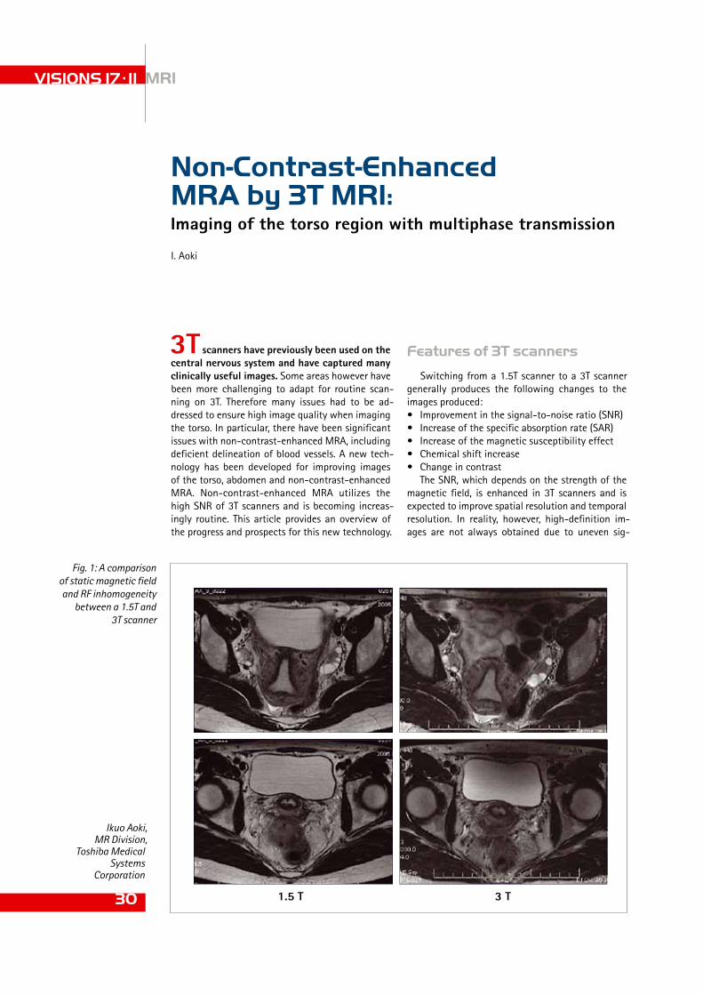
3T scanners have previously been used on the central nervous system and have captured many clinically useful images. Some areas however have been more challenging to adapt for routine scan-ning on 3T. Therefore many issues had to be ad-dressed to ensure high image quality when imaging the torso. In particular, there have been significant issues with non-contrast-enhanced MRA, including deficient delineation of blood vessels. A new tech-nology has been developed for improving images of the torso, abdomen and non-contrast-enhanced MRA. Non-contrast-enhanced MRA utilizes the high SNR of 3T scanners and is becoming increas-ingly routine. This article provides an overview of the progress and prospects for this new technology.
I. Aoki
Imaging of the torso region with multiphase transmission
Non-Contrast-Enhanced MRA by 3T MRI:
VISIONS 17 . 11 MRI
30
Fig. 1: A comparison of static magnetic field and RF inhomogeneity
between a 1.5T and 3T scanner
1.5 T 3 T

Fig. 2: Optimization of the B1 distribution according to the ideal rotational field
of slices and inversely proportional to the TR, is re-stricted by the SAR. Consequently, the imaging con-ditions must be modified, such as reducing the flip angle (FA), extending the repetition time (TR) and/or reducing the number of slices. The advantages of 3T MRI cannot be exploited under such circumstances, making it impossible to obtain the high resolution images that were originally expected of 3T scanners. Even the contrast effects that are routinely obtained
nal response caused by inhomogeneity in the static magnetic field (B0) and the RF field (B1) as well as other factors. Currently 3T scanners have an SNR 1.2 to 1.8 times that of 1.5T scanners at most when imaging the abdominal region.
Meanwhile, the SAR is proportional to the square of the strength of the static magnetic field (B0). Fur-thermore, the duty cycle, which is the RF pulse fre-quency per unit of time, proportional to the number
31
Fig. 3: Non-contrast-enhanced MRA of the hepatic artery utilising multiphase transmission1.5 T
3 T
TI 1200 TI 1500

signal intensity. This inhomogeneous signal is not an issue in 1.5T scanners. When imaging is performed without using a dielectric pad, for example in cases of ascites, the SNR in the core of the body decreases as shown in the bladder in Figure 1. Even if a dielec-tric pad is used, magnetic field in-homogeneity may remain and not be completely resolved.
High-performance RF signal technologyThe high-performance RF signal technology
known as multiphase transmission was developed to resolve this issue (Fig. 2). Multiphase transmis-sion is a technology that improves B1 homogene-ity by transmitting a for its phase and amplitude precisely adjusted signal. In addition, by increasing the number of power supply ports in an RF coil, the ideal current distribution is achieved and the B1 inhomogeneity, which is attributed to the electri-cal characteristics of the human body, is reduced. This controls fluctuations in signal intensity and stabilizes image quality for the first time leading to a greater degree of freedom in selecting imag-ing conditions. With the frequently used two-port transmission the uneven signal intensity in an im-age, which is attributed to uneven RF transmission, still persists. However, with four-port transmission B1 distribution is much more uniform and uneven signal intensity is significantly improved.
For example, in the past a full bladder would result in noticeable variation in signal intensity, whereas now variation-free images can be captured in a similar manner to an empty bladder (Fig. 2).
by 1.5T scanners further deteriorate. Thus, it has been impossible to obtain satisfactory image quality in the torso using 3T scanners.
The issue of RF field (B1) inhomogeneity in high magnetic fields
It is difficult to maintain magnetic field homoge-neity in devices with high magnetic fields. RF field (B1) inhomogeneity is particularly problematic in the torso due to the dielectric effect. This leads to an increase in signal strength fluctuation and im-age degradation. Traditionally this has been resolved by using dielectric pads. By placing such dielectric material on the surface of the body excess RF signals are absorbed, thereby improving inhomogeneous
VISIONS 17 . 11 MRI
32
Fig. 4: Non-contrast-enhanced
MRA of the portal vein and hepatic
artery utilising multi-phase transmission
Fig. 5: High-precision
3D non-contrast-
enhanced MRA
MR VenographyMR Portography@ 3T

chyma is low and contrast is preserved, but the blood ves-sels are not visualized to the periphery. When TI is changed to 1500 ms to improve visuali-zation of the peripheral vessels,
although they are visualized to the periphery, the signal in the liver parenchyma rises, and the de-lineation of the hepatic artery is less than optimal. Conversely with a 3T scanner, the contrast effect is clear all the way to the periphery of the hepatic artery due to suppression of the background signal, even with a long TI.
Improvement in spatial/temporal resolution
In MR venography and MR portography, clini-cally acceptable images can be obtained even if the imaging time is reduced by up to two-thirds (Fig. 4).
Under 3T MRI, higher definition images and shorter imaging time can be expected compared to 1.5T scanners as a result of the enhanced SNR. However, in the past, images captured at certain examinations were not of a quality that could be used satisfactorily in routine practice, and the much anticipated high SNR could not be utilized.
The present situation will be resolved by intro-ducing this new technology. The potential ability of 3T scanners, even in the torso region, will probably be maximized in the future by the new RF transmis-sion technology known as multiphase transmission. Greater improvements in image quality and reduced imaging time can be expected for non-contrast-enhanced MRA of the torso for which expectations are particularly high (Fig. 5).
By combining dimensional volume rendering at-tained by CT diagnosis with various three-dimen-sional processing techniques, 3T MRI might lead to a paradigm shift in diagnostic imaging of the abdomen in the near future (Fig. 6).
This article is an excerpt provided by Toshiba Medical Systems Corp. based on the content of a seminar presented at the 69th Annual Meet-ing of the Japan Radiological Society of 2010 entitled, “Next-Genera-tion Three-Tesla MRI That is Safe for Patients: Innovation in Three-Tesla Imaging of the Abdomen” (Dr. Hiroyoshi Isoda, Radiology and Nuclear Medicine Service, Kyoto University Hospital).
References1 Miyazaki, M., V.S. Lee. 2008. Nonenhanced MR Angiography.
Radiology 248(1): 20–43.
Expectations for 3T non-contrast-enhanced MRA
For 3T scanners Time Of Flight (TOF) has tradi-tionally been used as the non-contrast-enhanced MRA technique. TOF enables images that harness a high SNR to be captured, particularly in the brain. Conversely, there are many problems with non-contrast-enhanced MRA of the torso which, as discussed in the previous section, prevent reliable image quality. However, images of the torso can now be captured by non-contrast-enhanced MRA due to the benefits of the increased performance provided by recent improvements to RF transmis-sion technology.
Non-contrast-enhanced MRA using 3T MRI is expected to result in the following:• Improvement in the SNR• Improvement in spatial resolution (MR arteriog-
raphy)• Reduced imaging time (MR venography and MR
portography)Although 1.5T scanners provide adequate im-
age quality with regard to MR venography and MR portography, 3T scanners enable the imaging time to be reduced, and increase the degree of freedom in imaging.
Contrast improvement in non-contrast- enhanced MRA due to background signal suppression
In 3T scanners tissue-unique T1 values are longer than those for 1.5T scanners. This enables back-ground signals to be suppressed in images with a long TI. For example, in MRA of the hepatic ar-tery using a 1.5T scanner, the signal in the liver parenchyma, which forms the background signal following TI recovers, resulting in reduced contrast of blood vessels. In 3T scanners, with a long TI, the background signal is suppressed due to prolonga-tion of T1 values, which is expected to improve con-trast of blood vessels.
As Figure 3 shows, in the case of a 1.5T scanner, at a TI of 1200 ms, the signal in the liver paren-
33
Fig. 6: 3D image of the pancreas

Advances both in transducer design and IT ca-pability have generated high quality 3D imaging particularly when used with transvaginal scan ning (TVS). As a result, 3D technology is now an integral part of gynaecological ultrasound in leading scan units. To date 4D (i.e. real-time 3D) scanning has had little to offer in terms of gynaecological ultrasound.
Volumetric facilities are now incorporated within most ultrasound systems. The principal operational controls and functions are similar from system to system, although terminology may obviously vary from one to another.
3D image formatsThe so-called sweep scan produces a volume
of ultrasound data. This can be displayed in the following formats.
Introduction3D volumetric ultrasound is shown to be of tremendous value particularly in gynaecology and associated clinical areas. The combination of modern 3D technology and high resolution trans-vaginal scanning provides increased anatomical and clinical detail. Furthermore it offers considerable benefits from a practical point of view. Nevertheless, its role in gynaecological ultrasound has yet to be fully realised.
A single automated sweep of the ultrasound beam through a selected volume of tissue or specific organs produces a wealth of diagnostic information. Rapid acquisition and storage of ultrasound data, speedy retrieval of stored data and easy manipula-tion of retrieved images considerably reduce exami-nation times. This has obvious positive implications both for the patient as well as the management of busy scan lists.
B. Smith
The Practical Application and Clinical Use of Modern 3D Ultrasound Technology in Gynaecology
VISIONS 17 . 11 ULTRASOUND
34

Fig. 1a: Compound image (x, y, z components + BVI) demonstrating antral follicle distribution, ovarian stroma, endometriotic cyst (E) and internal iliac vessel (V).
viewed simultaneously in three orthogonal planes, i.e. 3D slices at right angles to one another. MPR provides increased anatomical information and greatly improved delineation of pelvic structures within a single image display.
Multi ViewMulti View images (also known as tomographic
ultrasound imaging, TUI) consist of tomographic sec-tions through any of the individual MPR image planes. Multi View provides very effective analysis of ana-tomical details and associated clinical information within any localised region of the pelvis or specific organ. It enhances clinical communication to a con-siderable extent and offers valuable support to ultra-sound scan reporting (Fig. 1b, 3b and 6b).
Block volume imagingBlock volume imaging (BVI) displays internal,
ortho gonal anatomical planes within a given block volume. Its practical and diagnostic value is lim-
Compound imagingThe compound image consists of standard x, y and z image components (i.e. parasagittal, transverse and coronal anatomical planes). An additional image is also displayed, usually in surface rendered or block volume format (Fig. 1a and 2a).
The four displays within the compound image are quickly assessed and if satisfactory are instantane-ously stored at the press of a button. The stored information is transferred to the system memory or hard disc. This data can be retrieved at any stage for further manipulation and evaluation of anatomi-cal planes. The retrieved ultrasound data can then be displayed and recorded in a number of ways or further image formats.
Multi-planar imagingMulti-planar imaging (MPR) comprises of the x,
y and z (parasagittal, transverse and coronal) com-ponents of a given Compound Image. This allows a specific structure or area within an organ to be
35
Fig. 1b: Multi View images from the x component of Fig. 1a displaying the complete ovarian morphology and associated features. The extent of the endometriotic cyst (E) is completely demonstrated. The ovarian capsule is outlined and para-ovarian structures such as the pelvic vessel (V) are easily separated from ovarian features.
Fig. 1: 3D imaging formats of a multifollicular ovary containing an endometriotic cyst
Fig. 1c: Block volume clearly delineating the endometriotic cyst (E) and preservation of normal, healthy ovarian tissue.
Fig. 1d: Surface rendered image of endometriotic cyst content (E) and cavities of multiple follicles (f). Normal ovarian stroma (ov. strom) is very obvious.

36
recordings of the baby is well established but its clinical impact to date appears to be relatively limited. This is currently reflected in general pel vic scanning with little application in terms of gynaecological ultrasound to date.
3D colour Doppler imagingAdvanced 3D technology incorporates colour
Doppler (power Doppler) imaging. 3D reconstruc-tion of imaging planes and volumetric studies demonstrate blood flow within tissues down to the capillary level and the vascular nature of pel-vic lesions. The ability to show tissue vascularity is important in the assess ment of diffuse disease and detection of high risk pathological changes in particular. Blood flow indices can provide quantitative measurement of tissue vascularity within a selected volume.
ited but it can be useful when displaying adjacent features which lie in a random manner in different anatomical planes (Fig. 1c).
Surface renderingSurface rendered images (SRI) display anatomi-
cal structures with a visual 3D effect. SRI provides greater delineation and increased visual impres-sion of the physical nature of pelvic lesions. It can de monstrate the nature of cavities as well as give an impression of the external features of structures. In addition, it allows the separation of pelvic organs to be visualised with greater clarity (Fig. 1d and 9d).
4D ultrasound4D ultrasound utilises advanced IT capability
to produce real-time 3D SRI ultrasound imaging. Its role in obstetric scanning and creating image
VISIONS 17 . 11 ULTRASOUND
Fig. 2: 3D imaging formats of a normal uterus and uterine cavity
Fig. 2a: Compound image (x, y, z components + SRI) demonstrating a normal endometrial cavity (Endom). Note the interstitial portion of the uterine tube (I) visualised on the rendered image.
Fig. 2b: A surface rendered image in Cavity Mode clearly highlights the interstitial tube (I).
Fig. 3: Bicornuate uterus
Fig. 3a: Composite image of a parasagittal 2D section of the uterus and endometrial cavity (Endom) and coronal MPR of an obvious bicornuate cavity (Bicorn Ut).
Fig. 3b: Multi View coronal sections outlining the extent of the anatomical malformation.

37
The basic technical requirements of a modern 3D system include the following:
• Uncomplicated, user-friendly controls for acquisition and storage, retrieval, post-scan ma-nipulation and image recording of ultrasound information.
• Simple initiation of a single, automated 2D scan-ning (“survey”) sweep of the area of interest. A stable, high quality greyscale image maintained throughout the survey sweep.
• Rapid acquisition and viewing of stored scan information. Immediate transfer of acquired ultra sound data to the system memory or a ser-ver or deletion of stored data if not required.
• Uniform spatial and contrast resolution in the greyscale image in all anatomical planes within the ultrasound volume.
• Accurate geometric registration of echo point sources within the 3D volume.
• Rapid, easy retrieval of stored ultrasound data.It is important to notice that the quality of 3D imaging reflects that of the fundamental 2D greyscale performance levels of the ultrasound system. Correct utilisation of 2D system controls and greyscale pre-sets is essential in order to maximise the dia gnostic information provided by 3D ultrasound technology.
3D volumetric technology presents considerable benefits from a practical point of view:
Principles of 3D volumetric imaging
A conventional 2D (TVS) ultrasound image or sector is usually generated by electronically steering a narrow ultrasound beam through the body tissues. The size of the 2D image, or anatomical slice, depends upon the 2D sector angle and depth of field of view selected.
A 3D volume is created by generating a rapid series of 2D scan sweeps, each very slightly dis-placed perpendicular to the direction of the scan sweep. A large number of sequential 2D anatomi-cal slices are built up to produce in effect a 3D volume. The size of the volume will be deter-mined by the distance between first and final 2D anatomical slice creating the volume, i.e. 3D sec-tor angle, as well as the 2D sector angle utilised and depth of field selected.
The volume information acquired is displayed straight away usually in the form of a stored Compound Image for direct viewing. The ultra- sound data stored can then be transferred to the system memory or a server for future inter rogation or simply deleted if not required.
Practical aspectsTechnical considerations
3D (TVS) ultrasound scanning is both convenient and straight-forward from a practical point of view.
Fig. 4a and 4b: Composite parasagittal 2D and surface rendered 3D images of the uterine cavity. The SRI reference plane (SR) has been shifted and slightly curved in Fig. 4b to accommodate both the uterine cavity and cervical canal. As a result the rendered image clearly demonstrates the complete cavity from the internal os to fundus compared to only the cavity of the uterine body in Fig. 4a.
Fig. 4: 3D – TVS SIS or “fluid ultrasound” demonstrating a normal uterine cavity.
Fig. 4c: Multi View coronal sections fully demonstrate the extent and nature of the uterine cavity in a single image.

38
It is important to ensure the correct use of 2D controls in order to maintain optimal 3D detail. These include selection and utilisation of transducer frequency, focal length and zone, 2D sector angle, frame rate/PRF, image size etc. as well as sensitivity controls and greyscale preset functions.
The survey sweep allows (2D) visualisation of the area of interest as the system collects the 3D data. This in itself can be of considerable diagnostic and practical value. It is therefore important that a constant level of greyscale imaging is maintained throughout the duration of the 3D sweep.
Acquisition and storage of 3D volumesThe 3D sampling box or sector is superimposed
upon the realtime 2D image.The survey or 3D sweep should be adjusted
to cover the area of interest only. This involves appropriate selection of both 3D sector angle and the depth of the 3D sample sector or box. The detail obtained from ultrasound images derived from the stored 3D data largely depends upon the follow-ing factors:
• Correct use of 2D greyscale controls• 3D sector angle• 3D sweep speed• Depth of 3D sample sector
The selection of 3D sector angle, sweep speed and sampling box size greatly influences frame rates and hence line density within the 3D image volume. These are important considerations in the ability to maximise 3D image quality. The absence of tis-sue movement problems in general pelvic scanning, certainly compared with ultrasound of the fetus, allows slower sweep speed and improved 3D image definition. 3D sweep scans can typically take 4–8 seconds in gynaecological ultrasound.
• Reduces scanning time and length of the ultrasound examination.
• Reduced examination time for the patient and exposure to ultrasound energy.
• Promotes the concept of post-scan evaluation.• Reduces probe movement as part of TVS in order
to acquire ultrasound information and therefore causes less discomfort particularly with patients presenting with pelvic pain.
• More efficient and cost-effective storage and archiving of image material compared to conventional 2D image recording.
Scanning issues3D ultrasound scanning involves in practice
holding the TVS transducer stationary and initiat-ing the single 3D survey sweep. The survey sweep produces the 3D volumetric data which can then be stored once the Compound Image has been assessed.
VISIONS 17 . 11 ULTRASOUND
Fig. 5: 3D – TVS SIS demonstrating an endometrial polyp and submucosal fibroids encroaching on the uterine cavity.
Fig. 5a: Compound image (x, y, z components + BVI) demonstrating the relevant clinical features.
Fig. 5b: Multi View coronal sections showing the position and nature of the polyp (P) and indentation of the cavity by the mid-uterine fibroid (M).
Fig. 5c: Composite parasagittal 2D and surface rendered 3D sections. Adjustment of the reference plane (SR) produces a localised rendered image of the mid-upper cavity with encroaching fibroids (M) and polyp (P) delineated.

particular features or tissue changes to be visually enhanced in order to highlight diagnostic findings.
Similarly, the surface rendered image (SRI) can be geometrically manipulated. There are also post-processing options specific to SRI again serving to visually outline structures with greater clarity. These include:
• Cavity Mode: This essentially reverses the grey-scale or selected colour mapping, i.e. making cystic regions lighter and solid regions darker (inversion, see Fig. 6).
• Threshold Control: This is basically a control which determines the level to which ultrasound information is suppressed for surface rendering (mainly low level clutter and noise).A combination of algorithms, typically available
in most systems, enables adjustment to be made regarding colour, surface textured appearances, transparency of structures etc. within the rendered volume.
The SRI reference plane (SR) determines the thick ness or at what depth the rendered image is visualised. The level can be adjusted under visu-
The acquired ultrasound data is usually immedi-ately displayed in the form of a stored Compound Image. This can be manipulated and/or converted into other forms of 3D imaging if required. Other-wise the volume data can be very quickly transferred to the system memory, hard disc or server, or other-wise instantaneously deleted.
Retrieval and manipulation of 3D volumesStored volumetric data is usually retrieved in
the Composite Image format. All components can be manipulated simultaneously or independent of one another.
MPR images can be rotated in any geometric plane. It is also possible to scroll through the volume thick ness in any one of the anatomical planes. Al-ternatively, Multi View will generate a series of to-mographic images within that plane. The number of image slices as well as the distance between slices making up the Multi View format can be varied.
The greyscale characteristics of the retrieved MPR and/or Multi View can be varied by means of a number of post-processing options. This allows
39
Fig. 6: ART stimulated multifollicular ovary
Fig. 6a: Compound imaging (x, y, z components + BVI) provides immediate visualisation of the number, distribution and relative sizes of stimulated follicles.
Fig. 6b: Multi View delineates multiple follicles – the facility to scroll through the retrieved tomographic sections enables rapid evaluation and speedy measurements of developing ovarian follicles. This proves to be a considerable asset in terms of the monitoring and measurement of ovarian follicle response to ART stimulation.
Fig. 6c: Surface rendered images of the ovary highlighting individual follicles with considerable clarity.
Fig. 6d: Cavity Mode further enhances visualisation and provides precise delineation of the multiple follicles.

ing the extent of endometrial malignancy. Volu-metric assessment of blood flow changes within the myometrium also demonstrates diffuse benign disease. This has increased our ability to confirm the likelihood of adenomyosis in particular and has been an important element in the early detection of endometriosis.
3D volumetric ultrasound has had a major clini-cal impact in other areas of gynaecology. More com-prehensive examination of the myometrium, uterine cavity and endometrium greatly assists investiga-tion of fertility issues and possible causes of recur-rent miscarriage.
Ovaries3D volumetric ultrasound presents the ideal im-
aging modality for examining ovarian morphology. MPR, Multi View and a choice of surface rendered displays offer very precise imaging of follicle pat-terns and stromal distribution within the ovary. This has proved invaluable both in the assessment of gynae cological disease as well as the investigation of fertility and ovulatory issues (Fig. 6 and 7).
Improved delineation and interrogation of ovarian lesions provides a more reliable diagnos-tic impression of their nature. 3D imaging formats accurately gauge the preservation of normal, func-tional ovarian tissue in the presence of large le-sions. This remains crucial in terms of clinical management and choice of surgical techniques if indicated. The introduction of 3D colour Doppler differentiates between high and low risk lesions with far greater diagnostic confidence.
The additional use of SRI facilities not only outlines pelvic structures with greater clarity but
al control and the shape of the SR can be curved in order to demonstrate non-linear anatomical sec-tions (Fig. 4 and Fig. 5c).
Clincial aspects Uterus
3D reconstruction of the uterus and uterine cav-ity in coronal section is a considerable asset par-ticularly with access to Multi View formats. The anatomy of the uterus and presence of uterine le-sions prove to be much more recognisable even to the untrained eye in this image plane.
The shape and size of the uterine cavity is clearly demonstrated and anatomical malformation read-ily identified in the coronal plane. The combination of MPR and Multi View formats provide precise location of IUD/IUS devices in-utero and confirms the presence, size, position and nature of intra-cavital lesions such as polyps, fibroids, adhesions etc. (Fig. 2 and 3).
The utilisation of 3D TVS technology as part of Saline Infusion Sonohysterography (SIS), or “fluid ultrasound”, procedures increases the diagnostic effectiveness of ultrasound examination of the endometrium and uterine cavity. MPR, Multi View and manipulation of SR (coronal) displays present very detailed studies of the distended cavity and any associated pathologies. In a number of clinical units, 3D TVS SIS has proven to be an appropriate alterna-tive to diagnostic hysteroscopy with obvious advan-tages to both the clinic and patient (Fig. 4 and 5).
3D TVS provides more elaborate evaluation of endometrial changes. The introduction of 3D colour Doppler is shown to be extremely useful in terms of identifying high risk changes as well as gaug-
VISIONS 17 . 11 ULTRASOUND
40
Fig. 7: Perimenopausal ovary with an intact follicular cyst (C¹) and remnants of a collapsing, clot-filled cyst (C²)
Fig. 7a and 7b: Compound imaging (x, y, z components + BVI) and Multi View sections provide complete details of ovarian morphology and as-sociated lesions. The functional cysts are seen quite separately from one another. The nature of the ovarian stroma can be easily evaluated. The absence of antral follicles remains consistent with patient age.

41
significant pelvic discomfort. The TVS probe is held still in order to carry out 3D scan sweeps and gently repositioned in only a selected number of locations in order to interrogate all areas of interest.
Post-scan evaluation Scan reporting
Modern 3D volumetric ultrasound promotes the possibility of post-scan evaluation. The speed of sys-tem operation and quality of stored images makes it convenient and reliable to consider reporting of ultrasound examinations at a later time after the scan has been completed.
The survey sweep itself should be adequate to serve as an initial evaluation of relevant structures or areas of interest in a large number of cases. Mini-mal scanning only is sometimes required to view the pelvic structures and select relevant areas for speedy acquisition and storage of scan details. As a result, scanning times are considerably reduced certainly in more straightforward, non-complex cases.
The facility to connect the ultrasound system to a suitable IT workstation means reporting of scans can be easily carried out remotely and at anytime following completion of the scan or scan list. This has practical advantages certainly in the manage-ment of busy scan lists and regarding efficiency of
can distinguish between ovarian and adjacent para-ovarian features with more certainty. This is particularly useful in examination of the adnexal regions and associated pathologies involving the Fallopian tube.
Pelvis (general)Complex, diffuse gynaecological disease affect-
ing adjacent organs or structures within the pelvic cavity are very often difficult to evaluate by conven-tional 2D TVS ultrasound scanning. This might in-clude for example chronic PID, extensive pelvic en-dometriosis or the spread of malignancy.
The facility to retrieve 3D ultrasound data and carefully examine different anatomical planes us-ing a choice of 3D imaging formats is a tremen-dous benefit in these cases. Individual, neighbour-ing structures involved with the spread of disease can be recognised more easily and the extent of the disease estimated with greater diagnostic accuracy (Fig. 8 and 9).
3D volumetric ultrasound is a particular asset for those patients presenting with moderate to severe endometriosis. These patients experience considera-ble discomfort during a conventional TVS ultrasound examination. The ability to restrict probe movement to a minimum is a major consideration especially in these cases and also for any patient experiencing
Fig. 8: Adherent ovary with extensive adnexal/pelvic adhesions and loculated fluid collections.
Fig. 8c: Composite image of 2D and SRI 3D images. The rendered image highlights remnants of the corpus luteum (CL) and visualises the fluid cavities (c) resulting from the multiple bands of adhesions clearly evident.
Fig. 8a: Localised 2D image of the adnexal region shows a complex mass.
Fig. 8b: Multi View sections through the area outlined in Fig. 8a clearly demonstrate the ovary (Ov) adherent to the pelvic sidewall with numerous, extensive bands of adhesions. Associated loculated fluid contains clot which has probably resulted from spill from the collapsed corpus luteum (CL) just visible within the ovary.

VISIONS 17 . 10 ULTRASOUND
4242
VISIONS 17 . 11 ULTRASOUND
Multi View and volume rendering, can make the content of the ultrasound image much more apparent. Multi View coronal sections of the uterus or SRI of the adnexal region for exam-ple result in much more obvious detail as part of the images used to support written texts.
Volumetric imaging formats produced from the retrieved data can be of value to referring clinicians in terms of pre-surgical planning. 3D volumetric ultrasound reconstruction in modern systems can be utilised in a similar manner to MRI regarding image interpretation and clinical communication.
patient throughput. In addition, it has been shown that post-scan evaluation of 3D images in more complex clinical cases, especially those involving extensive, diffuse pelvic change, is extremely useful in terms of accuracy of diagnosis.
Clinical communicationUltrasound images remain an essential part of
ultrasound scan reporting. Standard 2D grey-scale images can be difficult to interpret both in terms of the anatomy and clinical features shown, particularly to the untrained eye. 3D reconstruction, especially the use of MPR,
Fig. 9: Early tubal ectopic pregnancy (5+ weeks gestation) and associated haematosalpinx
Fig. 9a: Multi View coronal sections confirm an obvious decidual esponse but no intra-uterine pregnancy sac was identified.
Fig. 9b: Compound imaging (x, y, z + SRI) identifies the ovary (Ov), a para-ovarian mass (T), a fimbrial cyst (F) with an early extra-uterine pregnancy sac (G) outlined on the rendered image. Manipulation of the anatomical planes allows more effective examination and recognition of relevant structures.
Fig. 9c: Localised Multi View sections show the distended, blood-filled uterine tube (UT) immediately adjacent and probably adherent to the ovary (Ov). The fimbrial cyst (F) is again well seen and free fluid (clot) present within the pelvic/adnexal region.
Fig. 9d: Composite image of an individual MPR section showing the tubal mass (T), fimbrial cyst (F) and ovary (Ov) and surface rendering of the adnexal structures. The rendered image shows the convoluted nature of the tube (UT) and its attachment to the ovary (Ov).

43
VISIONS 17 . 11NEWSAquilion RX – the next generation 16-slice CT scanner
Toshiba has rolled out Aquilion RX, a new 16-slice scanner which incorporates the latest dose-saving technologies based on iterative dose reduction.
It offers maximum performance for customers who need to perform a wide variety of routine clini-cal examinations in a streamlined workflow with the objective of delivering the best diagnostic quality at a minimal level of radiation exposure.
New product features“Ultra-low-dose examinations”
Using AIDR, image noise levels can be reduced by up to 50%. At comparable quality, the dose can be low-ered by up to 75% compared to conventional scanners. Images iteratively processed with AIDR assure superb image quality at the minimum dose.
“Ultra-flexible workflow”A new computer platform for Aquilion RX provides
a 60% faster reconstruction time. SUREXtension, a thin-client display station, makes it possible to review imag-es anywhere in the hospital without relying on a PACS system, increasing patient throughput and shortening waiting times.
“Quantum detector technology”Aquilion RX incorporates Toshiba’s exclusive Quan-
tum Detector technology. The 0.5-mm element size and state-of-the-art reconstruction guarantee highly detailed imaging. Using the full width of the detector, fast scanning over a long range can be achieved in the case of emergencies or if there are breath-holding restrictions.
“Wide Application range”The sophisticated suite of applications implement-
ed in Aquilion RX supports all the clinical needs that a 16-slice scanner is expected to meet. A powerful 7.5-MHU tube ensures that scans can be performed without leading to unnecessary waiting times.
Aquilion RX, Toshiba’s new 16-slice detector CT scanner incorporating
the latest dose-saving technologies based on iterative dose reduction
CT scan of a liver tumor made with Toshiba’s Aquilion RX

The major challenge is the detection of isolated cleft palate. The prenatal detection rate of isolated cleft palate approaches zero (0 –1.4 %)3-8 which shows that obviously at present there are no satis-factory sonographic indicators available to confirm the existence of isolated cleft palate. Because of its dome-shaped structure, the palate cannot be visual-ized in its entirety in 2D. Moreover, the surrounding osseous structures further complicate the evaluation due to imaging artifacts in the region of interest.
Presenting different case studies, this paper will not only show that CLP and CP can be diagnosed in 2D but also how to perform this examination.
IntroductionWith an incidence of about 1:1000 births, facial
clefts are among the most frequently occurring con-genital malformations1,2. They can take on various forms, but from a pathophysiological point of view cleft lip and palate (CLP) significantly differ from isolated cleft palate (CP). In CLP the defect always starts at the lip and extends to a variable degree in a dorsal direction (lip notch, cleft lip, CLP (hard palate only or hard and soft palate)). Isolated cleft palate always starts at the uvula (uvula bifida as the mildest form) and to a variable extent proceeds along the midline in anterior direction. It either affects only the soft palate or the soft and hard palate. Both CLP and CP can occur as isolated malformations or as compo-nents of chromosomal or syndromal disorders7.
While prenatal detection of CLP during a dif-ferentiated ultrasound examination is usually fairly unproblematic, it is significantly more difficult to evaluate the palate structures involved in CLP to assess the extent of the malformation.
L. Wilhelm
2D Sonographic Evaluation of Fetal Facial Clefts
VISIONS 17 . 11 ULTRASOUND
44
Fig. 1: Frontal facial view with depiction of lips, nose with nostrils and chin
Lucas WilhelmPractice for
prenatal diagnostics and therapy
HürthGermany

The integrity of the maxilla is evaluated in the axial view at the level of the upper jaw which also allows checking the continuity of the upper lip (Fig. 2). The hard palate, however, cannot be depicted in this way, since it is partly out of plane and ultrasound artifacts prevent an evaluation behind the bone.
Case studies 1) Normal findings
Lips are best evaluated in a frontal view with depiction of the upper lip, lower lip and nose with nostrils (Fig. 1), which in most cases allows confirma-tion of the integrity of the upper lip.
45
Fig. 2: Axial view at the level of the upper jaw with depiction of the unremarkable maxilla ()
Fig. 4: Depiction of the uvula (οO) as a typical “equals sign” in a tilted, more posterior transverse view at the level of the base of the skull
Fig. 6: Depiction of the entire palate in a median sagittal view with neck extended. Hard palate () soft palate ()with uvula (οO).
Fig. 3: Frontal view of the neck with depiction of the uvula ( O “equals sign”). The key structure to find the uvula in this view is the epiglottis ().
Fig. 5: Depiction of the soft palate ()with uvula (οO)in a median sagittal view
Fig. 7: Depiction of a lip defect on the left side in frontal view ()

VISIONS 17 . 11 ULTRASOUND
46
Fig. 8: Axial view at the level of the upper jaw with confirmation of an intact maxilla (οO)
Fig. 10: Depiction of an intact palate ()with uvula ο(οO) in a median sagittal view
Fig. 9: Unremarkable uvula (οO) in a frontal view through the pharynx
Fig. 11: Postpartum image with confirmation of the isolated lip defect
Fig. 12: Depiction of an extensive lip defect () on the right side in a frontal view
Fig. 13: Depiction of a discontinuity in the maxilla ()
in axial view at the level of the upper jaw

47
Fig. 14: Detection of the absence of palate structures including the uvula ()in a median sagittal view
Fig. 16: Postpartum image with confirmation of the prenatal diagnosis. The visible clip () is not a palate structure, but a device used for orthodontic therapy.
Fig. 15: Detection of the absence of the uvula in a frontal view through the pharynx (οO) ; epiglottis ()
Fig. 17: Depiction of lip involvement () in a frontal view with CLP on the left side
Fig. 18: Detection of the maxillary defect ()in axial view
Fig. 19: In a median sagittal view only one palate structure can be depicted that stands out as an uvula (οO) . Otherwise, it is not
possible to visualize a portion of the soft or the hard palate ().
Because direct and complete evaluation of the entire palate is impossible, the relevant parts of the palate have to serve as reference points while the typical pathophysiology of the different types of
clefts has to be taken into consideration. Confirma-tion of an intact upper lip rules out a cleft palate in CLP. An unremarkable uvula rules out isolated cleft palate, because with isolated cleft palate the uvula
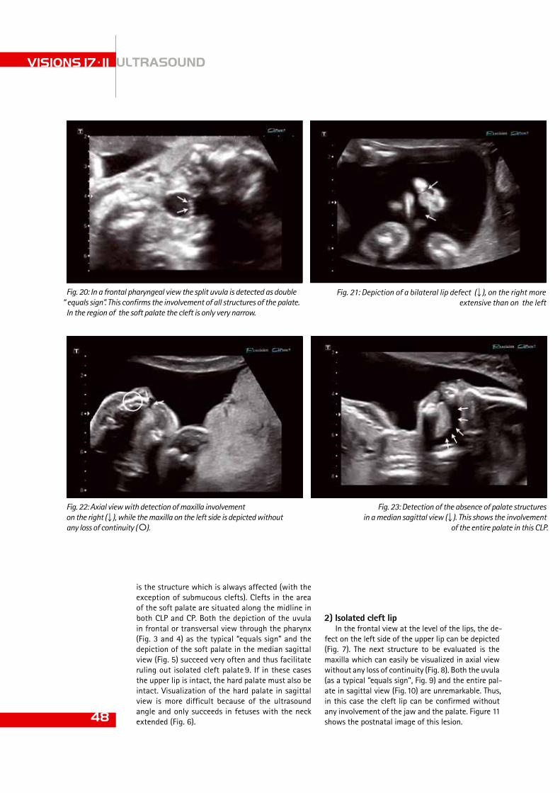
VISIONS 17 . 11 ULTRASOUND
48
Fig. 20: In a frontal pharyngeal view the split uvula is detected as double “ equals sign”. This confirms the involvement of all structures of the palate.
In the region of the soft palate the cleft is only very narrow.
Fig. 21: Depiction of a bilateral lip defect (), on the right more extensive than on the left
Fig. 23: Detection of the absence of palate structures in a median sagittal view (). This shows the involvement
of the entire palate in this CLP.
is the structure which is always affected (with the exception of submucous clefts). Clefts in the area of the soft palate are situated along the midline in both CLP and CP. Both the depiction of the uvula in frontal or transversal view through the pharynx (Fig. 3 and 4) as the typical “equals sign” and the depiction of the soft palate in the median sagittal view (Fig. 5) succeed very often and thus facilitate ruling out isolated cleft palate 9. If in these cases the upper lip is intact, the hard palate must also be intact. Visualization of the hard palate in sagittal view is more difficult because of the ultrasound angle and only succeeds in fetuses with the neck extended (Fig. 6).
2) Isolated cleft lipIn the frontal view at the level of the lips, the de-
fect on the left side of the upper lip can be depicted (Fig. 7). The next structure to be evaluated is the maxilla which can easily be visualized in axial view without any loss of continuity (Fig. 8). Both the uvula (as a typical “equals sign”, Fig. 9) and the entire pal-ate in sagittal view (Fig. 10) are unremarkable. Thus, in this case the cleft lip can be confirmed without any involvement of the jaw and the palate. Figure 11 shows the postnatal image of this lesion.
Fig. 22: Axial view with detection of maxilla involvement on the right (), while the maxilla on the left side is depicted without any loss of continuity (οO).

ible palate structures in the median sagittal view confirms palate involvement (Fig. 14). This is sup-ported by the fact that the uvula cannot be detected (Fig. 15). The postpartum image confirms the prena-tal diagnosis (Fig. 16). 49
Fig. 24: Detection of the absence of the uvula (οO) above the epiglottis ()
Fig. 26: Frontal view with depiction of an unremarkable oral-nasal region
Fig. 25: Postpartum image which confirms the prenatal diagnosis.
Fig. 27: While examining the pharyngeal space, the uvula (οO) cannot be visualized above the epiglottis ().
Fig. 28: Detection of the absence of the palate structures in a median sag-ittal view () resulting in the certain diagnosis of an isolated cleft palate
Fig. 29: Postnatal image with depiction of the isolated cleft palate (hard and soft palate)
3) Unilateral CLPIn frontal view a large defect of the upper lips
on the right side can be easily visualized (Fig. 12). The axial view at the level of the upper jaw shows the continuity loss of the maxilla and confirms the involvement of the jaw (Fig. 13). The absence of vis-

References 1 Gregg T, Bod D, Richardson A. The incidence of cleft lip and palate in
Northern Ireland from 1980 –1990. Br J Orthod 1994; 21: 387-392 2 Coupland MA, Coupland AI. Seasonality, incidence and sex distribu-
tion of cleft lip and palate birth in Trent region (1973-82). Cleft Palate J 1988; 25: 33-37
3 Grandjean H, Larroque D, Levi S. The performance of routine ultra-sonographic screening of pregnancies in the Eurofetus Study. Am J Obstet Gynecol 1999; 181: 226-454
4 Clementi M, Tenconie R, Bianchi F, Stoll C. Evaluation of prenatal diagnosis of cleft lip with or without cleft palate and cleft palate by ultrasound: experience from 20 European registries. EUROSCAN study group. Prenat Diagn 2000; 20: 870-875
5 Shaikh D, Mercer NS, Sohan K, Kyle P, Soothill P. Prenatal diagnosis of cleft lip and palate. Br J Plastic Surg 2001; 54: 288-289
6 Offerdal K, Jebens N, Syvertsen T, Blaas HGK, Johansen OJ, Eik-Nes SH. Prenatal ultrasound detection of facial clefts: a prospective study of 49 314 deliveries in a non-selected population in Norway. Ultrasound Obstet Gynecol 2008; 31: 639-646
7 Gillham JC, Anand S, Bullen PJ. Antenatal detection of cleft lip with or without cleft palate: incidence of associated chromosomal and structural anaomalies. Ultrasound Obstet Gynecol 2009; 34: 410-415
8 Cash C, Set P, Colemann N. The accuracy of antenatal ultrasound in detection of facial clefts in a low risk screening population. Ultra-sound Obstet Gynecol 2001; 18: 432-436
9 Wilhelm L, Borgers B. The equals sign: a novel marker in the diag-nosis of fetal isolated cleft palate. Ultrasound Obstet Gynecol 2010; 36: 439-444
VISIONS 17 . 11 ULTRASOUND
50
4) Unilateral CLP with detection of a split uvula
The frontal view shows a cleft in the region of the left upper lip (Fig. 17) which is not as extensive as in the previous case. Moreover, the defect in the maxilla, which is seen in the axial view, is not very extensive (Fig. 18). The anterior portion of the soft palate cannot be depicted in median sagittal view, but an uvula can be seen (Fig. 19). The examination of the uvula in frontal view through the pharynx shows a completely split but very closely spaced uvula (double “equals sign”, Fig. 20). The diagnosis was confirmed after birth, but postpartum images for this child were regrettably unobtainable.
5) Bilateral CLPThe frontal view shows a bilateral cleft of the up-
per lip. The defect is more pronounced on the right side than on the left side (Fig. 21). In the axial view the right-side defect of the maxilla can be depicted while the continuity on the left side is completely preserved (Fig. 22). The median sagittal view with absent depiction of soft palate structures confirms the involvement of the entire palate (Fig. 23). This is supported by the inability to detect the uvula in the frontal view through the pharynx (Fig. 24). The postpartum image confirms the prenatal diagnosis of CLP with bilateral lip involvement as well as jaw and complete palate involvement on the right side (Fig. 25).
6) Isolated cleft palate (CP)The frontal view of the face shows the integrity
of the upper lip but no cleft (Fig. 26) while the ex-ploration of the pharynx does not show an uvula (Fig. 27) which indicates isolated cleft palate. In median sagittal view neither parts of the soft palate nor the hard palate can be depicted (Fig. 28) which points at a more extensive isolated cleft palate. This was confirmed postpartum (Fig. 29).
ConclusionThe consistent and systematical exploitation of
the 2D ultrasound capabilities allows the compre-hensive diagnosis of fetal facial clefts and of the extent of CLP, including palate involvement. This had previously been a major challenge. The systematic exploration of the fetal pharyngeal space focusing on finding and depicting the uvula allows the inves-tigator to detect an indication of isolated cleft palate which previously had been viewed as essentially un-diagnosable. An unremarkable uvula, which can be depicted as a typical “equals sign”, rules out isolated cleft palate. If the uvula cannot be detected, the soft palate must be depicted in sagittal view. If the soft palate cannot be depicted, isolated cleft palate can also be diagnosed with certainty.

Vascular Freedom in X-Ray Imaging
ULTRASOUND CT MRI X-RAY SERVICES
www.toshiba-europe.com/medical
Radiology demands speed, precision and optimum performance. Toshiba designed the Infinix VF-i to meet these requirements by taking advantage of the very latest technological innovations, dramatically reducing procedure time and risk during catheterization.
The unique five axis design of the Infinix VF-i equals the flexibility of a ceiling suspended system, giving radiologists exceptional access to the patient and full anatomical coverage without the need for table-movement. The 12”x16” Flat Panel Detector delivers distortion-free high-quality DSA images for multiple applications, for both radiology and cardiology. An intuitive programmable graphic user interface and comprehensive dose management guarantee high workflow and safety for patient and operator.
Infinix VF-i combines superb image quality, flexibility and safety to ensure clinical imaging procedures that are fast, safe and precise. This revolutionary system is the embodiment of Toshiba’s philosophy to improve the quality of life, simultaneously providing you with the best tools available to boost your imaging capabilities.
Toshiba: Made for Patients, Made for You, Made for Life!
3D DA Carotid Artery
Tumor Fed by Femoral Artery

www.toshiba-medical.eu/VISIONS
ULTRASOUND CT MRI X-RAY SERVICES
www.toshiba-medical.eu
Register online for VISIONS And stay up-to-date with the latest innovations in medical imaging
Subscribe for VISIONS and have digital access to the latest edition of VISIONS magazine and all other articles that have been published in previous editions of VISIONS.
Just visit our website at www.toshiba-medical.eu/VISIONS
Do you also want to receive a paper copy of VISIONS magazine at home or at work? Please tell us so during registration and we will send you VISIONS magazine twice a year! Registration is easy and absolutely free.
Toshiba_advertentie VISIONS_V2.indd 1 16-02-2011 08:47:11