16.810: Engineering Design and Rapid Prototypingweb.mit.edu/16.810/www/16.810 SolidWorks,...
33
16.810: Engineering Design and Rapid Prototyping (IAP 2004 course number: 16.682) SolidWorks, CosmosWorks, Omax, and Water Jet Manual Version 1.0 Bill Nadir 12/16/2003 [email protected]
Transcript of 16.810: Engineering Design and Rapid Prototypingweb.mit.edu/16.810/www/16.810 SolidWorks,...

16.810: Engineering Design and Rapid Prototyping
(IAP 2004 course number: 16.682)
SolidWorks, CosmosWorks, Omax, and Water Jet Manual
Version 1.0 Bill Nadir 12/16/2003 [email protected]

Purpose The purpose of this document is to provide a rough procedure of how to perform many of the tasks required of students in 16.810 (temporary class number 16.682 in IAP 2004). Basic procedures of how to model a part in SolidWorks, perform structural analysis using CosmosWorks, and how to use the computer-aided manufacturing (CAM) tools for manufacturing with a water jet cutter are detailed in this document. This document is not meant to be complete and questions should be referred to the instructors or to another reference document. A flow chart of the various tasks covered in this document is shown below in Figure 1.
Figure 1 Flow chart
Table of Contents PURPOSE ..................................................................................................................................................... 2 TABLE OF CONTENTS ............................................................................................................................. 2 TABLE OF FIGURES ................................................................................................................................. 3 PROCEDURE FOR CREATING SOLIDWORKS CAD MODEL OF A 2-D PART ............................. 4 PROCEDURE FOR COSMOSWORKS STRUCTURAL ANALYSIS OF CAD MODEL OF A 2-D PART............................................................................................................................................................. 6 PROCEDURE FOR CREATING SOLIDWORKS DRAWING OF A 2-D PART................................ 20 PROCEDURE FOR CREATING OMAX LAYOUT OF A 2-D PART................................................. 21
2

Table of Figures FIGURE 1 FLOW CHART................................................................................................................................... 2 FIGURE 2 SOLIDWORKS MODEL TREE WINDOW ............................................................................................... 4 FIGURE 3 EXTRUDE DIALOG BOX.................................................................................................................... 5 FIGURE 4 STUDY DIALOG BOX ........................................................................................................................ 6 FIGURE 5 MATERIAL DIALOG BOX .................................................................................................................. 7 FIGURE 6 RESTRAINT DIALOG BOX ................................................................................................................. 7 FIGURE 7 SELECTION OF RESTRAINT SURFACES.............................................................................................. 8 FIGURE 8 RESTRAINTS DEFINED ..................................................................................................................... 8 FIGURE 9 LOAD/RESTRAINT IN MODEL TREE .................................................................................................. 9 FIGURE 10 FORCE DIALOG BOX FOR LOAD ON 2-D PART............................................................................... 10 FIGURE 11 RESULT OF FORCE AND RESTRAINT DEFINITIONS (2D VIEW) ....................................................... 10 FIGURE 12 MESH PREFERENCES DIALOG BOX ............................................................................................... 11 FIGURE 13 MESH PROPERTIES DIALOG BOX .................................................................................................. 11 FIGURE 14 MESH RESULT WITH RESTRAINTS AND LOADS DISPLAYED........................................................... 12 FIGURE 15 MODEL TREE HIGHLIGHTING STUDY TO SELECT TO RUN ANALYSIS ............................................. 12 FIGURE 16 MODEL TREE AFTER ANALYSIS WITH RESULT FOLDERS............................................................... 13 FIGURE 17 STRESS ANALYSIS RESULT PLOT.................................................................................................. 13 FIGURE 18 DISPLACEMENT ANALYSIS RESULT PLOT..................................................................................... 14 FIGURE 20 DISPLACEMENT PLOT DEFINITION DIALOG BOX........................................................................... 14 FIGURE 19 SELECTION OF PART FEATURE ON WHICH TO MEASURE DISPLACEMENT ...................................... 15 FIGURE 21 "LIST SELECTED" DIALOG BOX DISPLAYING NODE DISPLACEMENTS ........................................... 16 FIGURE 22 MASS PROPERITES WINDOW ........................................................................................................ 16 FIGURE 23 MASS PROPERTIES OPTIONS DIALOG BOX .................................................................................... 17 FIGURE 24 DESIGN CHECK PLOT SHOWING AREAS WITH A FACTOR OF SAFETY BELOW 1 (RED, CIRCLED) ..... 18 FIGURE 25 DESIGN CHECK WIZARD DIALOG BOXES ...................................................................................... 19 FIGURE 26 FACTOR OF SAFETY DISTRIBUTION PLOT ..................................................................................... 19 FIGURE 27 SOLIDWORKS DRAWING VIEW WITH DESIRED VIEW OF PART SELECTED....................................... 20 FIGURE 28 ERASING UNWANTED LINES IN OMAX LAYOUT ............................................................................. 21 FIGURE 29 OMAX LAYOUT "CLEAN" DIALOG BOX .......................................................................................... 22 FIGURE 30 BEFORE AND AFTER MOVING PART IN OMAX LAYOUT ................................................................... 22 FIGURE 31 OMAX LAYOUT CUT QUALITY DIALOG BOX................................................................................... 22 FIGURE 32 OMAX LAYOUT "PATH" CREATION WINDOW................................................................................. 23 FIGURE 33 TURNING WATER ON/OFF TO WATER JET CUTTER ........................................................................ 24 FIGURE 34 LOCATION OF POWER SWITCH TO WATER JET SYSTEM................................................................. 24 FIGURE 35 TURNING ON/OFF POWER TO WATER JET CUTTER ........................................................................ 25 FIGURE 36 OMAX MAKE "CHANGE PART SETUP" DIALOG BOX...................................................................... 26 FIGURE 37 OMAX MAKE WINDOW ................................................................................................................. 27 FIGURE 38 WATER JET DATA INFORMATION LOG BOOK................................................................................ 27 FIGURE 39 ABRASIVE CONTAINER FOR WATER JET CUTTER.......................................................................... 28 FIGURE 40 SETUP OF PART TO CUT WITH WATER JET CUTTER ....................................................................... 29 FIGURE 41 NOZZLE POSITION WINDOW......................................................................................................... 29 FIGURE 42 NOZZLE POSITIONED AT DESIRED (0,0) LOCATION (HOME).......................................................... 30 FIGURE 43 POSITIONING THE HEIGHT OF THE WATER JET CUTTER NOZZLE ................................................... 30 FIGURE 44 LOCATION OF LEVER TO LOCK-IN DESIRED HEIGHT OF WATER JET CUTTER NOZZLE.................... 31 FIGURE 45 WATER LEVEL RAISED - READY TO BEGIN MACHINING................................................................ 32 FIGURE 46 BEGIN MACHINING DIALOG BOX.................................................................................................. 32 FIGURE 47 WATER JET CUTTER IN OPERATION.............................................................................................. 33
3

Procedure for Creating SolidWorks CAD Model of a 2-D Part
1. Open SolidWorks 2003 2. File>New>Part>OK 3. Make sure units for the part are in inches
a. To verify what unit system is being used, click on Tools>Options>Document Properties tab>Units (in the tree) and verify that “Linear Units” are in inches.
4. Click on “Front” plane in model tree
Figure 2 SolidWorks model tree window
5. Click on “Sketch” icon (upper right-hand corner) 6. Sketch part (see “40 minute start” section in SolidWorks manual for reference)
a. Use lines, arcs, etc. (icons found on right-hand side of window)
b. Dimension the sketch appropriately using the dimension icon i. Lines in the sketch will turn black (initially blue) when fully
dimensioned c. When finished, click on the sketch icon with the arrow in the upper right-
hand corner of the sketch window 7. Extrude the sketch to create a 3-D model of the bicycle frame design
a. Click on the “Extrude” icon in the top of the left-hand side column of icons
b. In the “Extrude” dialogue box, input the desired thickness of the part c. Click on the green check mark to complete the extrusion
4

Figure 3 Extrude dialog box
8. How to manipulate the view of the part in the SolidWorks window
a. To spin the part, hold down the middle mouse button and move the mouse b. To zoom in on the part, point the cursor on the desired area to zoom in/out
and scroll the mouse wheel up/down c. To translate the part, hold down CTRL and the middle mouse button and
move the mouse 9. Save the part to file
a. File>Save As…>partname.prt
5

Procedure for CosmosWorks Structural Analysis of CAD Model of a 2-D Part
1. Open CosmosWorks 2003 2. File>Open>partname.prt>OK 3. Click on “CosmosWorks Manager” tab at the bottom of the FeatureManager tree
4. Right-click on the part in the FeatureManager tree and select “Study…” 5. Fill out Study dialog box
a. Type in a desired name for the study under “Study Name” b. Select “Static” in the box under “Analysis Type” c. Select “Solid mesh” in the box under “Mesh type”
Figure 4 Study dialog box
6. Set material properties for the part
a. Right-click on the part name under “Solids” in the model tree b. Click on “Apply/Edit Material…” c. Make sure library file source is Coswkmat.lib d. In the material tree, open Aluminum Alloys and select 6061 alloy e. Make sure the “Type” under “Material model” is set to “Linear Elastic
Isotropic” f. Click OK when finished
6

Figure 5 Material dialog box
7. Define boundary conditions
a. Right-click on “Load/Restraint” in the tree b. Select “Restraints” c. Under “Type,” select “Reference Plane or Axis”
Figure 6 Restraint dialog box
d. Hold CTRL and pick the inside surfaces of the two fixed holes (in green)
7
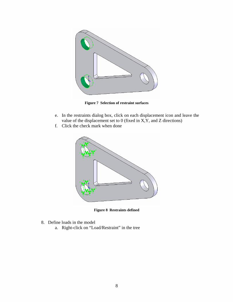
Figure 7 Selection of restraint surfaces
e. In the restraints dialog box, click on each displacement icon and leave the
value of the displacement set to 0 (fixed in X,Y, and Z directions) f. Click the check mark when done
Figure 8 Restraints defined
8. Define loads in the model
a. Right-click on “Load/Restraint” in the tree
8
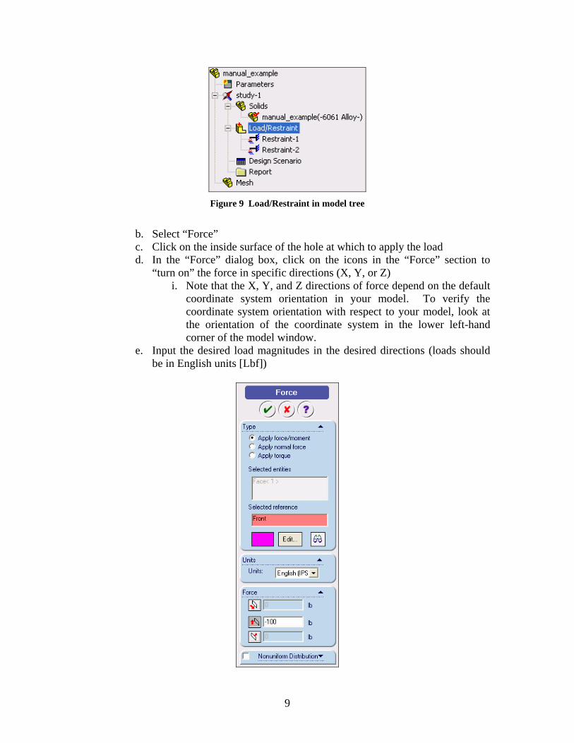
Figure 9 Load/Restraint in model tree
b. Select “Force” c. Click on the inside surface of the hole at which to apply the load d. In the “Force” dialog box, click on the icons in the “Force” section to
“turn on” the force in specific directions (X, Y, or Z) i. Note that the X, Y, and Z directions of force depend on the default
coordinate system orientation in your model. To verify the coordinate system orientation with respect to your model, look at the orientation of the coordinate system in the lower left-hand corner of the model window.
e. Input the desired load magnitudes in the desired directions (loads should be in English units [Lbf])
9

Figure 10 Force dialog box for load on 2-D part
f. Click the green check mark when finished g. Repeat steps a through f for the second hole at which load is applied
Figure 11 Result of force and restraint definitions (2D view)
9. Create desired mesh on part to analyze
a. Right-click on “Mesh” in the tree and select “Preferences” b. Edit mesh preferences
i. Under “Mesh Quality,” select “High” ii. Under “Mesh Control,” select “Smooth Surface”
iii. Under “Mesher Type,” select “Standard” iv. Set “Jacobian Check” to “4 Points” v. Click OK
10

Figure 12 Mesh preferences dialog box
c. Create mesh
i. Right-click on “Mesh” in the tree and select “Create” ii. “Mesh parameters” dialog box will appear
1. Adjust mesh properties if desired
Figure 13 Mesh properties dialog box
d. To display detailed information about the mesh, right-click “Mesh” in the
tree and select “Details”
11

Figure 14 Mesh result with restraints and loads displayed
10. Perform structural analysis
a. In the model tree, right-click on the study created and click “Run”
Figure 15 Model tree highlighting study to select to run analysis
11. Display results of analysis
a. After analysis has been run, additional folders will appear in model tree
12

Figure 16 Model tree after analysis with result folders
b. Display von Mises stress results
i. Click the plus sign beside the “Stress” folder ii. Double-click on “Plot1” and the stress plot is displayed
Figure 17 Stress analysis result plot
c. Display resultant displacement
i. Click the plus sign beside the “Displacement” folder ii. Double-click on “Plot1” and the displacement plot is displayed
iii. Read displacements at surface being measured during the structural testing phase (surface circled in figure below)
13

Figure 18 Displacement analysis result plot
d. Procedure to display displacements (magnitudes) at specific nodes on the
part i. Create a new displacement plot
1. Right click on “Displacement,” click “Define…” 2. Click on the “Display” tab, select plot type to be “Vector,”
and select fringe type to be “point” 3. Select component as the displacement in the desired
direction (X, Y, or Z) and click “OK”
Figure 19 Displacement plot definition dialog box
14

ii. Right-click on new displacement plot and click “List Selected”
iii. In the model window, click on a surface, edge, or vertex on which to determine the displacements at the nodes on that entity
1. Please note that you will need to select a surface, edge, or vertex on the non-deformed part. This part may not be visible, but the available surfaces, edges, and vertices on the non-deformed part can be selected from the screen. They will be outlined in red when the cursor is over one of the entities that can be selected. See figure below.
Figure 20 Selection of part feature on which to measure displacement
iv. Click “Update” in the List Displacements dialog box v. Displacement results are then displayed for the nodes on the
surface, edge, or vertex selected along with the sum and average of the calculated displacements.
15
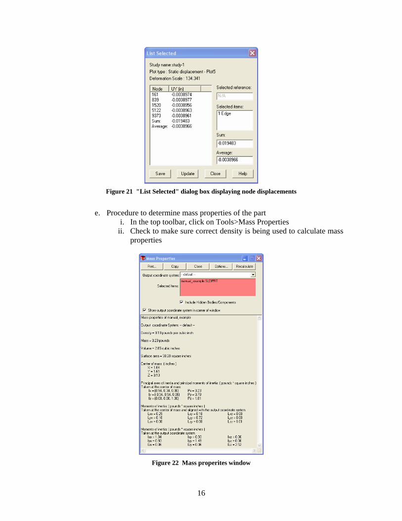
Figure 21 "List Selected" dialog box displaying node displacements
e. Procedure to determine mass properties of the part
i. In the top toolbar, click on Tools>Mass Properties ii. Check to make sure correct density is being used to calculate mass
properties
Figure 22 Mass properites window
16

iii. If density is wrong, click on the “Options” button at the top of the
mass properties window and change the density in the options window
Figure 23 Mass properties options dialog box
f. Procedure to display critical regions of part (check part factor of safety)
i. Click the plus sign beside the “Design Check” folder ii. Double-click on “Plot1” and a design check wizard dialog box
appears iii. In step 1, make sure the criterion is set to “Maximum von Mises
stress” iv. In step 2, make sure stress limit is set “to Yield strength”
(determined from materials database) v. In step 3, to see unsafe regions in the part, make sure “areas below
factor of safety” is selected and input a desired factor of safety limit that you are using for your design
1. A factor of safety distribution can also be displayed by selecting “Factor of Safety distribution” in the “Plot Results” section of the step 3 dialog box.
2. Notice that in the step 3 dialog box a factor of safety for the part is displayed in the “Safety result” section of the window. This factor of safety is a good indicator of the structural performance of the part being analyzed.
17

Figure 24 Design check plot showing areas with a factor of safety below 1 (red, circled)
g. A report can be generated by right-clicking on the “Report” folder in the
model tree and clicking “define” i. Fill out the required fields and click “ok” to generate an HTML
report of the part structural analysis.
18

Figure 25 Design check wizard dialog boxes
Figure 26 Factor of safety distribution plot
19

Procedure for Creating SolidWorks Drawing of a 2-D Part
1. Open SolidWorks 2003 2. File>New>Drawing>OK 3. Click OK for default drawing template 4. Insert>Drawing View>Standard 3 View 5. Right-click in drawing and then select “Insert from file” 6. Pick desired SolidWorks part to import into drawing 7. Move desired view of part (top-down view) into the center of the drawing (make
sure it is not being overlapped by any other lines in the drawing) a. Click on the desired drawing view b. When a green line surrounds the view, click on the green edge and drag
the view to a location of your choice
Figure 27 SolidWorks drawing view with desired view of part selected
8. File>Save As…>(choose *.dxf as file type)>filename.dxf
20
Procedure for Creating Omax Layout of a 2-D Part
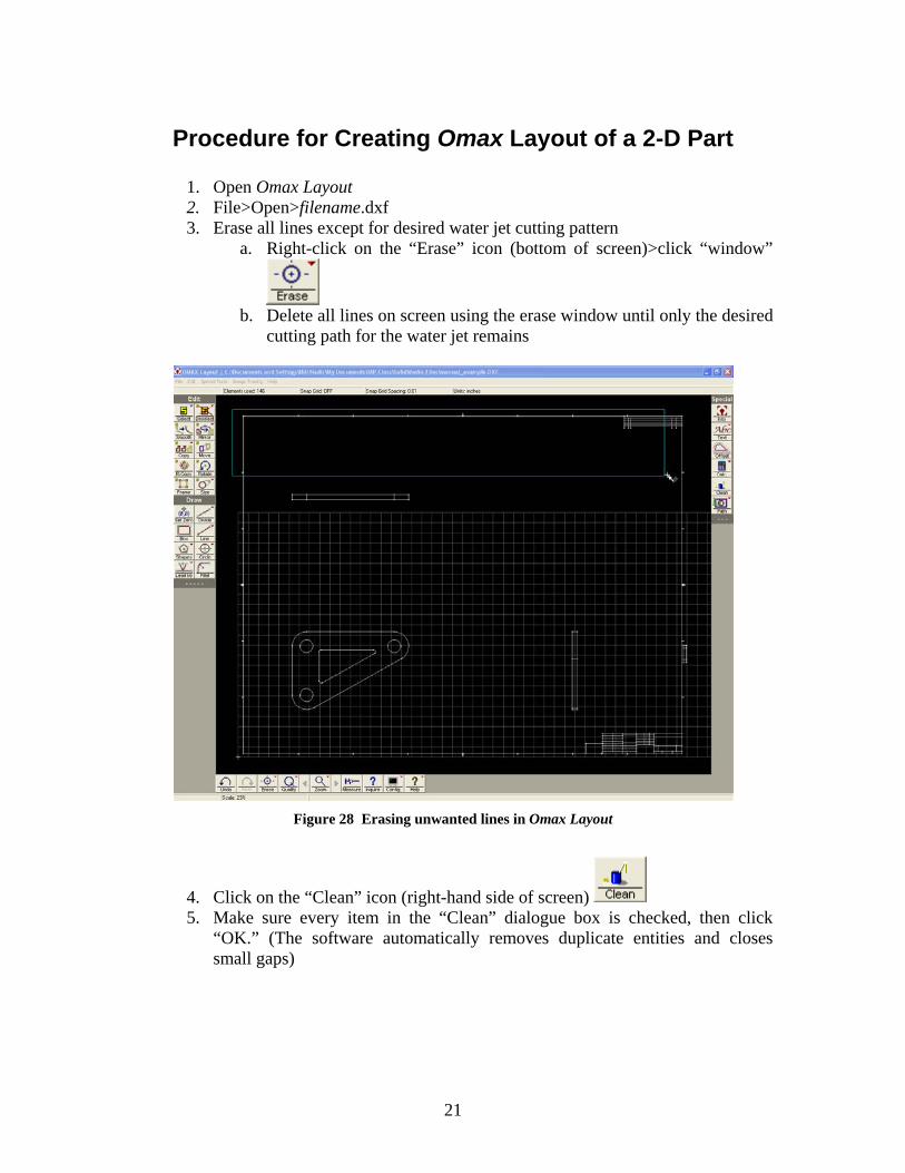
1. Open Omax Layout 2. File>Open>filename.dxf 3. Erase all lines except for desired water jet cutting pattern
a. Right-click on the “Erase” icon (bottom of screen)>click “window”
b. Delete all lines on screen using the erase window until only the desired
cutting path for the water jet remains
Figure 28 Erasing unwanted lines in Omax Layout
4. Click on the “Clean” icon (right-hand side of screen) 5. Make sure every item in the “Clean” dialogue box is checked, then click
“OK.” (The software automatically removes duplicate entities and closes small gaps)
21

Figure 29 Omax Layout "clean" dialog box
6. Resize part due to potential scaling error of imported DXF file
a. Click on the “Size” icon (left-hand side of screen) b. Input desired width or height of part to scale the part to the correct size
7. Move part into the grid in the lower left-hand corner of the workspace by
clicking on the “Move” icon
Figure 30 Before and after moving part in Omax Layout
8. Right-click on “Deselect” icon (left-hand side of screen)>Click “All” 9. Set cutting quality for part
a. Type “Q” then “A” (brings up quality selection dialogue window for all curves)
Figure 31 Omax Layout cut quality dialog box
22
b. Click on “5” to set a quality level of 3 (medium quality) for all part edges (curves should change to a magenta color)
c. Type “Q” again and click on a quality level of 5 and then click on the curves which cut the faces of the part which face the lasers for displacement measurement as well as the mounting holes (these curves should turn to a blue color)
10. Set water jet cutting lead-in and finishing paths
a. Right-click on “Lead i/o” icon (left-hand side of screen) b. Click “AutoPath (quick)”
11. Modify lead-out path (The goal is to make sure nozzle moves far away from cut part when cutting is finished and to make it clear when the cutting job is complete.)
a. Click on the “Line” icon (right-hand side of screen) b. Click on the “End” icon which appears at the bottom of the screen
(this will attach the line to the end of the desired curve) c. Click on the end of the tan-colored line (end of the path) and extend it
far away from the part to move the water jet cutter away from the manufactured part when it is finished (make sure to not move the nozzle into a lead block or the tank side)
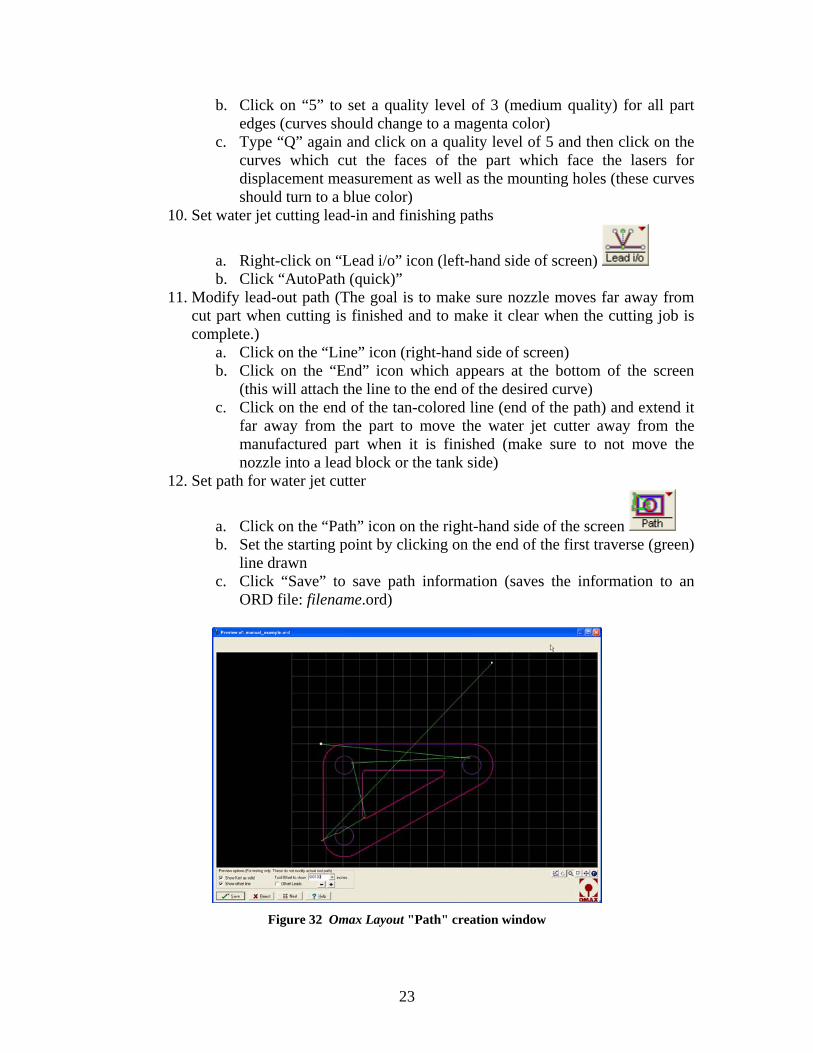
12. Set path for water jet cutter
a. Click on the “Path” icon on the right-hand side of the screen b. Set the starting point by clicking on the end of the first traverse (green)
line drawn c. Click “Save” to save path information (saves the information to an
ORD file: filename.ord)
Figure 32 Omax Layout "Path" creation window
23

Procedure for Manufacturing a 2-D Part
1. Sign in and put on protective goggles when you enter the machine shop 2. Turn on water to water jet cutter
a. Located on wall behind Omax computer terminal
Figure 33 Turning water on/off to water jet cutter
3. Turn power on to water jet system
a. Turn outer metal ring on the right-hand side of the computer terminal clockwise (hidden in picture)
Figure 34 Location of power switch to water jet system
24

4. Turn on power to water jet pump
a. Located on left-hand side of computer terminal stand
Figure 35 Turning on/off power to water jet cutter
5. Turn on personal computer located next to the water jet cutter 6. Run Omax Make software 7. File>Open>filename.ord (will need ORD file on a 3.5” floppy disk to load into
computer at water jet cutter) 8. Click on “Change Part Setup” icon
a. Check material, thickness, and tool offset information and change if necessary
b. Make sure low pressure boxes are left unchecked – use high pressure setting
25

Figure 36 Omax Make "Change Part Setup" dialog box
9. Once the “Change Part Setup” dialog box is filled-out correctly and the “OK”
button is clicked, Omax Make imports the cut path information and estimates manufacturing time, manufacturing cost, and amount of abrasive required for the cutting operation (circled in the following figure).
10. Omax Make can also display the cutting speed and cut direction along the cutting curves.
a. To display cut speed, click on the “Preview to Screen” icon
b. To display the cut directions, click on the icon at the bottom of the
Omax Make window.
26

Figure 37 Omax Make window
11. Fill out water jet cutter machine log (2 sections)
a. Read machine time off of water jet power control box before starting any machining.
Figure 38 Water jet data information log book
12. Put on latex gloves before using the water jet cutter 13. Prepare the water jet cutter for manufacturing part
a. Make sure the water jet cutter has enough abrasive for desired cutting operation
27

Figure 39 Abrasive container for water jet cutter
b. Make sure water level in water jet cutter is lowered (below the metal
grate) i. If it is too high, lower the water level by using the lever on the
computer terminal c. Make sure the water jet nozzle is raised up about 12 inches above the
metal grate to allow room for placing manufacturing material in the cutter i. Raise nozzle with the circular knob on nozzle shaft and tighten
with black lever arm on upper part of shaft d. Place material on metal grate (your aluminum sheet) e. Locate and orient material so as to make the cuts as they appear in the
Omax Make window f. Use lead bricks provided to weigh-down the aluminum plate to prevent it
from moving (IMPORTANT: wear protective gloves for this step)
28

Figure 40 Setup of part to cut with water jet cutter
g. Move the water jet nozzle above the desired starting position (home
position) i. Use the arrow keys on the keyboard to move water jet nozzle
Figure 41 Nozzle position window
h. Once nozzle is in the desired home position, click on the “000>Zero” icon
in the upper right-hand corner of the screen to specify the origin (0,0) of the water jet cutting nozzle
i. Note that the “right” and “down” directions shown in arrows in the following figure are identical to “right” and “down” in the Omax Make window.
29

Figure 42 Nozzle positioned at desired (0,0) location (home)
j. Place the plastic sponge on the end of the nozzle as shown in the figure k. Lower the nozzle to within approximately 0.030” of the material to be
machined i. Use .030” shim stock as a guide to measure the offset
1. A large enough gap between the nozzle and material should be left such that the shim stock can slide between the two references.
Figure 43 Positioning the height of the water jet cutter nozzle
ii. Tighten the nozzle firmly at the correct height offset
30

Figure 44 Location of lever to lock-in desired height of water jet cutter nozzle
l. Raise water level to just below overfill valves along the inner sides of the
water jet cutting tank i. Water should be covering the material to be machined and the
nozzle end 1. The water reduces the noise level during machining 2. If the machining noise level is intolerable, hearing
protection is provided.
31

Figure 45 Water level raised - ready to begin machining
14. Double check everything 15. IMPORTANT: Emergency stop of the water jet cutter can be accomplished by
hitting the spacebar on the computer keyboard or tripping the master power switch
16. Once you are certain everything has been setup properly, click on the “Begin
Machining” icon on the right-hand side of the screen 17. If you are sure you are ready to start cutting, click the “Start” icon (This will start
the cutting process!)
Figure 46 Begin machining dialog box
32
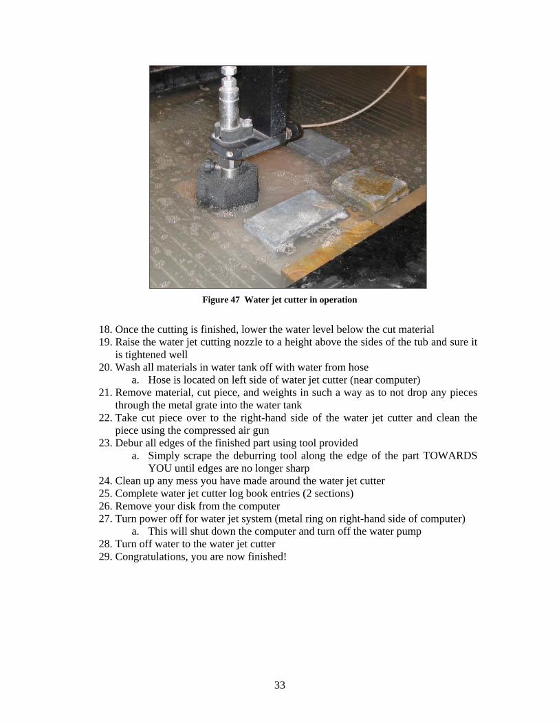
Figure 47 Water jet cutter in operation
18. Once the cutting is finished, lower the water level below the cut material 19. Raise the water jet cutting nozzle to a height above the sides of the tub and sure it
is tightened well 20. Wash all materials in water tank off with water from hose
a. Hose is located on left side of water jet cutter (near computer) 21. Remove material, cut piece, and weights in such a way as to not drop any pieces
through the metal grate into the water tank 22. Take cut piece over to the right-hand side of the water jet cutter and clean the
piece using the compressed air gun 23. Debur all edges of the finished part using tool provided
a. Simply scrape the deburring tool along the edge of the part TOWARDS YOU until edges are no longer sharp
24. Clean up any mess you have made around the water jet cutter 25. Complete water jet cutter log book entries (2 sections) 26. Remove your disk from the computer 27. Turn power off for water jet system (metal ring on right-hand side of computer)
a. This will shut down the computer and turn off the water pump 28. Turn off water to the water jet cutter 29. Congratulations, you are now finished!
33