1600-IP Series Product Manual - vikingelectronics.com
34
Features Applications Specifications www.VikingElectronics.com • Automatic polling and programming software included • 2 Amp relay contacts for door/gate or SL-2 strobe light control • SIP compliant (see page 2 for more information) • Outbound Proxy, Authentication ID, Peer to Peer, VLAN Tagging • PoE powered (class 1, <4 Watts) • Automatic Noise Canceling (ANC) feature for proper operation in noisy areas • VoIP eliminates the need for “Push to Talk” mode • Network downloadable firmware • Meets ADA requirements for Emergency Phones: - Automatically lights the Red “Call Connected” LED - Transmits a unique location I.D. code or voice announcement - Grade 2 Braille label for the visually impaired • Non-volatile digital voice announcer with 28 seconds of voice memory • Handsfree operation • Marine grade 316 stainless steel prevents corrosion on the stainless steel models • Laser etched graphics on stainless steel models • Dials up to 5 emergency numbers • E-1600-20-IP, E-1600-22-IP, E-1600-52-IP, and E-1600-TP2IPEWP dial up to 5 non- emergency “INFO” numbers • Cycles through backup phone numbers on busy or no-answer • Optional Enhanced Weather Protection (EWP), EWP products are designed to meet IP66 Ingress Protection Rating, see DOD 859 • Hangs up on busy signal, time-out or touch tone command • Extended temperature range (-40°F to 140°F) • 11 different chassis or board only available • Available in 42” tower phone model E-1600-BLTIPEWP (DOD 249) • Optional LV-1K Line verification Panel (DOD 246 ) • Optional PB-100 Polling System available (DOD 232) • Optional SL-2 or BLK-4-EWP strobe light kit available (DOD 242/654) • Optional E-1600A-MK-GNP Pedestal Mounting Kit (DOD 227) • Optional PB-1 Panic Button Kit (DOD 233) • Diagnostics for testing microphone, speaker, and relay Power: PoE class 1 (<4 Watts) Maximum Sound Pressure: 95 dB SPL @ 1m Dimensions: See Installation and Specifications Operating Temperature: -40°F to 140°F (-40° C to 60° C) Humidity - Standard Products: 5% to 95% non-condensing Humidity - EWP Products: Up to 100% Audio Codecs: G711u, G711a, G722 Network Compliance: IEEE 802.3 af PoE, SIP 2.0 RFC3261, 100BASE-TX with auto cross over Regulatory Compliance: CE, FCC Part 15 and Canada ICES-003 Class A Connections: (1) RJ45 10/100 Base-T, (3) gel-filled butt connectors * Americans with Disabilities Act of 1992 contains federal regulations regarding elevator telephones (Public Law 101-336). • Elevators • Parking ramps/lots • Emergency pool phones • ATM machines • Medical centers • Silent hold-up alarm dialer with an optional PB-1 Panic Button Kit (DOD 233) • Area of refuge locations • Lobbies • Entryways • Campus emergency stations • Stadiums • Convention centers • Public access areas ADA & CE Compliant VoIP Emergency Phones with Built-In Dialer and Digital Voice Announcer The 1600-IP Series of ADA Compliant VoIP Emergency Phones are designed to provide quick and reliable handsfree communication for SIP VoIP phone systems with PoE. All 1600-IP Series phones meet ADA requirements for elevator or emergency telephones, and can be programmed from any touch tone phone or PC on the same LAN or remotely using a static IP address. The phones can dial up to 5 programmable emergency numbers. In addition, the E-1600-20-IP, E-1600-22-IP, E-1600-52-IP and E-1600-TP2IPEWP feature a second "INFO" button that will dial up to 5 non-emergency numbers. Two amp relay contacts are provided for strobe light, camera, door/gate control, etc. The 1600-IP Series phones can be programmed to automatically deliver a digital announcement to identify the location of the emergency call. Alternatively, a DTMF touch tone code may also be delivered. A “Call Connected” LED can be initiated manually or automatically. All programming parameters, including phone numbers and location numbers, are stored in non-volatile memory, requiring no batteries. All units are PoE powered. For outdoor installations where the unit is exposed to precipitation or condensation, select 1600-IP Series phones are available with Enhanced Weather Protection (EWP). EWP products are designed to meet IP66 standards and may feature foam rubber gaskets, sealed connections, gel-filled butt connectors, as well as potted circuit boards with internally sealed, field-adjustable trim pots and DIP switches for easy onsite programming. For more information on EWP, see DOD 859. PRODUCT MANUAL Designed, Manufactured and Supported in the USA 1600-IP Series ADA Compliant VoIP Emergency Phones March 25, 2021 SECURITY & COMMUNICATION VIKING E-1600-45-IP E-1600-IP E-1600-03-IP E-1600-20-IP E-1600-55-IP E-1600-30-IP E-1600-65-IP E-1600-60-IP E-1600-32-IP E-1600-SS-IP E-1600-RD-IP E-1600-YL-IP E-1600-BL-IP E-1600-BLP-IP E-1600-BK-IP E-1600-02-IP/E-1600-TP-IPEWP E-1600-TP2IPEWP/E-1600-GT-IPEWP E-1600-50/52-IP E-1600-53-IP Installation requires a Network Administrator / IT Technician !
Transcript of 1600-IP Series Product Manual - vikingelectronics.com

Features Applications
Specifications
www.VikingElectronics.com
• Automatic polling and programming software included • 2 Amp relay contacts for door/gate or SL-2 strobe light control • SIP compliant (see page 2 for more information) • Outbound Proxy, Authentication ID, Peer to Peer, VLAN Tagging • PoE powered (class 1, <4 Watts) • Automatic Noise Canceling (ANC) feature for proper operation in noisy areas • VoIP eliminates the need for “Push to Talk” mode • Network downloadable firmware • Meets ADA requirements for Emergency Phones: - Automatically lights the Red “Call Connected” LED - Transmits a unique location I.D. code or voice announcement - Grade 2 Braille label for the visually impaired • Non-volatile digital voice announcer with 28 seconds of voice memory • Handsfree operation • Marine grade 316 stainless steel prevents corrosion on the stainless steel models • Laser etched graphics on stainless steel models • Dials up to 5 emergency numbers • E-1600-20-IP, E-1600-22-IP, E-1600-52-IP, and E-1600-TP2IPEWP dial up to 5 non-
emergency “INFO” numbers • Cycles through backup phone numbers on busy or no-answer • Optional Enhanced Weather Protection (EWP), EWP products are designed to meet
IP66 Ingress Protection Rating, see DOD 859 • Hangs up on busy signal, time-out or touch tone command • Extended temperature range (-40°F to 140°F) • 11 different chassis or board only available • Available in 42” tower phone model E-1600-BLTIPEWP (DOD 249) • Optional LV-1K Line verification Panel (DOD 246 ) • Optional PB-100 Polling System available (DOD 232) • Optional SL-2 or BLK-4-EWP strobe light kit available (DOD 242/654) • Optional E-1600A-MK-GNP Pedestal Mounting Kit (DOD 227) • Optional PB-1 Panic Button Kit (DOD 233) • Diagnostics for testing microphone, speaker, and relay
Power: PoE class 1 (<4 Watts) Maximum Sound Pressure: 95 dB SPL @ 1m Dimensions: See Installation and Specifications Operating Temperature: -40°F to 140°F (-40° C to 60° C) Humidity - Standard Products: 5% to 95% non-condensing Humidity - EWP Products: Up to 100% Audio Codecs: G711u, G711a, G722 Network Compliance: IEEE 802.3 af PoE, SIP 2.0 RFC3261, 100BASE-TX with auto cross over Regulatory Compliance: CE, FCC Part 15 and Canada ICES-003 Class A Connections: (1) RJ45 10/100 Base-T, (3) gel-filled butt connectors
* Americans with Disabilities Act of 1992 contains federal regulations regarding elevator telephones (Public Law 101-336).
• Elevators • Parking ramps/lots • Emergency pool phones • ATM machines • Medical centers • Silent hold-up alarm dialer with an optional PB-1 Panic Button Kit (DOD 233)
• Area of refuge locations • Lobbies • Entryways • Campus emergency stations • Stadiums • Convention centers • Public access areas
ADA & CE Compliant VoIP Emergency Phones with Built-In Dialer and Digital Voice Announcer
The 1600-IP Series of ADA Compliant VoIP Emergency Phones are designed to provide quick and reliable handsfree communication for SIP VoIP phone systems with PoE. All 1600-IP Series phones meet ADA requirements for elevator or emergency telephones, and can be programmed from any touch tone phone or PC on the same LAN or remotely using a static IP address. The phones can dial up to 5 programmable emergency numbers. In addition, the E-1600-20-IP, E-1600-22-IP, E-1600-52-IP and E-1600-TP2IPEWP feature a second "INFO" button that will dial up to 5 non-emergency numbers. Two amp relay contacts are provided for strobe light, camera, door/gate control, etc.
The 1600-IP Series phones can be programmed to automatically deliver a digital announcement to identify the location of the emergency call. Alternatively, a DTMF touch tone code may also be delivered. A “Call Connected” LED can be initiated manually or automatically. All programming parameters, including phone numbers and location numbers, are stored in non-volatile memory, requiring no batteries. All units are PoE powered.
For outdoor installations where the unit is exposed to precipitation or condensation, select 1600-IP Series phones are available with Enhanced Weather Protection (EWP). EWP products are designed to meet IP66 standards and may feature foam rubber gaskets, sealed connections, gel-filled butt connectors, as well as potted circuit boards with internally sealed, field-adjustable trim pots and DIP switches for easy onsite programming. For more information on EWP, see DOD 859.
PRODUCT MANUAL
Designed, Manufactured and Supported in the USA 1600-IP Series ADA Compliant VoIP Emergency Phones
March 25, 2021SECURITY & COMMUNICATIONVIKING
E-1600-45-IPE-1600-IP
E-1600-03-IP
E-1600-20-IP E-1600-55-IP
E-1600-30-IP
E-1600-65-IP E-1600-60-IP
E-1600-32-IP
E-1600-SS-IP E-1600-RD-IP E-1600-YL-IP E-1600-BL-IP E-1600-BLP-IP E-1600-BK-IP
E-1600-02-IP/E-1600-TP-IPEWP E-1600-TP2IPEWP/E-1600-GT-IPEWP
E-1600-50/52-IP
E-1600-53-IPInstallation requires a Network Administrator / IT Technician!

2
VoIP SIP System Compatibility
For compatibility and vendor specific detailed configuration instructions, see the Viking VoIP SIP System Compatibility List, DOD 944. To open and download this PDF file:
1. Go to www.vikingelectronics.com and enter 944 in the search box
2. Click Application Note (DOD 944) to open and download the PDF
Scan the QR code below to open and download the Viking VoIP SIP System Compatibility List
- OR -
Important: Exclusion from this list means only that compatibility has not been verified, it does not mean incompatibility. If you have questions, please call Viking Electronics at 715-386-8861.

3
Overview of Chassis and Mounting OptionsNote: When European CE compliance is required, mount open board models within a metal enclosure.
Model: E-1600-TP2IPEWP HxWxD: 11.75 x 9.5 x 2.0 Mounting: Flush mount Description: Direct physical replacement for Talk-A-Phone models ETP-400DV or VoIP-500D
Model: E-1600-GT-IPEWP HxWxD: 12.0 x 10.0 x 2.0 Mounting: Flush mount Description: Direct physical replacement for GAI-TRONICS Red Alert Model 397-700
Model: E-1600-IP HxWxD: 5.25 x 4.0 x 2.0 Mounting: Surface mount Description: 16 gauge steel with textured red powder paint
Model: E-1600-45-IP HxWxD: 5.25 x 4.0 x 2.0 Mounting: Surface mount Description: 16 gauge steel with textured yellow powder paint
Model: E-1600-60-IP HxWxD: 5.25 x 4.0 x 2.0 Mounting: Surface mount Description: 16 gauge steel with textured blue powder paint and “POLICE” verbiage
Model: E-1600-65-IP HxWxD: 5.25 x 4.0 x 2.0 Mounting: Surface mount Description: 16 gauge steel with textured blue powder paint
Model: E-1600-02-IP HxWxD: 13.0 x 10.5 x 2.0 Mounting: Flush mount Description: 12 gauge marine grade 316 stainless steel with #4 brushed finish
Model: E-1600-03-IP HxWxD: 7.22 x 5.36 x 1.55 Mounting: Surface mount Description: 14 gauge marine grade 316 stainless steel with #4 brushed finish
Model: E-1600-20-IP HxWxD: 5.0 x 5.0 x 2.25 Mounting: Flush mount with included rough-in box (will not fit in a double gang box), or surface mount with a VE-5x5 Description: Two button, 14 gauge marine grade 316 stain-less steel with #4 brushed finish, T-10 Torx Security Screws
Model: E-1600-22-IP HxWxD: 5.0 x 5.0 x 2.25 Mounting: Flush mount in a standard double gang electrical box or surface mount with a VE-5x5 Description: Two button, 14 gauge marine grade 316 stain-less steel with #4 brushed finish, T-10 Torx Security Screws
Model: E-1600-30-IP HxWxD: 5.0 x 5.0 x 2.25 Mounting: Flush mount with included rough-in box (will not fit in a double gang box), or surface mount with a VE-5x5 Description: 14 gauge marine grade 316 stainless steel with #4 brushed finish, T-10 Torx Security Screws
Model: E-1600-32-IP HxWxD: 5.0 x 5.0 x 2.25 Mounting: Flush mount in a standard double gang electrical box or surface mount with a VE-5x5 Description: 14 gauge marine grade 316 stainless steel with #4 brushed finish, T-10 Torx Security Screws
Model: E-1600-50-IP Description: Single button 1600-IP parts kit without chassis
Model: E-1600-52-IP Description: Two button 1600-IP parts kit without chassis
Model: E-1600-53-IP Description: 1600-IP board (PCB) only kit. Can be used to convert any analog Viking 1600A-Series phone to a VoIP version
Model: E-1600-55-IP HxWxD: 5.0 x 5.0 x 2.0 Description: Universal emergency phone kit to install behind elevator panels or when a custom panel is used
Model: E-1600-TP-IPEWP HxWxD: 11.75 x 9.5 x 2.0 Mounting: Flush mount Description: Direct physical replacement for Talk-A-Phone models ETP-400V or VoIP-500

4
Features Overview
Rear (PCB) View of E-1600-IP Series Emergency Phone
Connect to Optional Strobe Light, LV-1K, etc.
Viking model SL-2 shown (not included),
see DOD 242
|OR
|
MA
C:
18E80FXXXXXX
asdesaxtff
N.C. (Gray)
N.O. (Yellow)
COM. (Blue)
Optional 2 Amp Relay Output Contacts
(2A@30VDC / 250VAC max)
3 Gel-Filled ButtConnectors (included)
- Black
+ Red
Black
Black
- Black
+ Red
LED
Help Switch
Info Switch (optional)
Speaker
Microphone
MAC Address Label: The MAC address is a unique 12 digit number used by routers to send network traffic to the correct IP address.
PoE LAN Port 10/100, PoE Class 1 (<4 Watts): Connect to your LAN via RJ45 plug and CAT5 or greater twisted pair wire.
Yellow Network Status LED: Lights steady to indicate power and data link. Blinks to indicate network activity.
Green Unit Status LED
Red
Red
Yellow
Yellow
Viking model LV-1K shown (not included), see DOD 246
Note: The gel-filled (water-tight) butt connectors are designed for insulation displacement on 19-26 gauge wire with a maximum insulation of 0.082 inches. Cut off stripped wire ends before terminating.
5
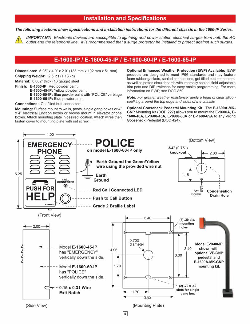
Installation and Specifications
E-1600-IP / E-1600-45-IP / E-1600-60-IP / E-1600-65-IP
The following sections show specifications and installation instructions for the different chassis in the 1600-IP Series.
2.00
4.00
5.25
0.703diameter
4.96 3.40
3.40
1.70
1.70
3.30
3.82
EMERGENCYPHONE
CALLCONNECTED
PUSH FOR
VIKING©
HELPGrade 2 Braille Label
Red Call Connected LED
Push to Call Button
POLICE
(Side View)
(Bottom View)
(Front View)
(Mounting Plate)
on model E-1600-60-IP only
Model E-1600-45-IPhas "EMERGENCY"vertically down the side.
Model E-1600-60-IPhas "POLICE" vertically down the side.
0.15 x 0.31 WireExit Notch
(4) .20 dia.mountingholes
(2) .20 x .40slots for single
gang box
Model E-1600-IP shown with
optional VE-GNP pedestal and
E-1600A-MK-GNP mounting kit.
EarthGround
Earth Ground the Green/Yellowwire using the provided wire nut
2.00
1.15
CondensationDrain Hole
3/4" (0.75”)knockout
SetScrew
IMPORTANT: Electronic devices are susceptible to lightning and power station electrical surges from both the AC outlet and the telephone line. It is recommended that a surge protector be installed to protect against such surges.
Dimensions: 5.25” x 4.0” x 2.0” (133 mm x 102 mm x 51 mm) Shipping Weight: 2.5 lbs (1.13 kg) Material: 0.062” thick (16 gauge) steel Finish: E-1600-IP: Red powder paint E-1600-45-IP: Yellow powder paint E-1600-60-IP: Blue powder paint with “POLICE” verbiage E-1600-65-IP: Blue powder paint Connections: Gel-filled butt connectors Mounting: Surface mount to walls, posts, single gang boxes or 4” x 4” electrical junction boxes or recess mount in elevator phone boxes. Attach mounting plate in desired location. Attach wires then fasten cover to mounting plate with set screw.
Optional Enhanced Weather Protection (EWP) Available: EWP products are designed to meet IP66 standards and may feature foam rubber gaskets, sealed connections, gel-filled butt connectors, as well as potted circuit boards with internally sealed, field-adjustable trim pots and DIP switches for easy onsite programming. For more information on EWP, see DOD 859.
Note: For greater weather resistance, apply a bead of clear silicon caulking around the top edge and sides of the chassis.
Optional Gooseneck Pedestal Mounting Kit: The E-1600A-MK-GNP Mounting Kit (DOD 227) allows you to mount the E-1600A, E-1600-40A, E-1600-45A, E-1600-60A or E-1600-65A to any Viking Gooseneck Pedestal (DOD 424).
6
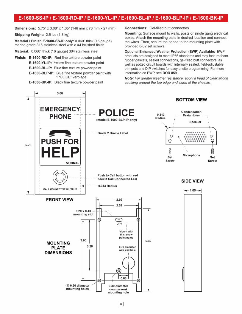
E-1600-SS-IP / E-1600-RD-IP / E-1600-YL-IP / E-1600-BL-IP / E-1600-BLP-IP / E-1600-BK-IP
Connections: Gel-filled butt connectors Mounting: Surface mount to walls, posts or single gang electrical boxes. Attach the mounting plate in desired location and connect the wires. Then, secure the phone to the mounting plate with provided 8-32 set screws. Optional Enhanced Weather Protection (EWP) Available: EWP products are designed to meet IP66 standards and may feature foam rubber gaskets, sealed connections, gel-filled butt connectors, as well as potted circuit boards with internally sealed, field-adjustable trim pots and DIP switches for easy onsite programming. For more information on EWP, see DOD 859. Note: For greater weather resistance, apply a bead of clear silicon caulking around the top edge and sides of the chassis.
FRONT VIEW
3.08
5.75
CALL CONNECTED WHEN LIT
EMERGENCYPHONE
PUSH FOR
VIKING©
HELP
1.05
POLICE(model E-1600-BLP-IP only)
Grade 2 Braille Label
SIDE VIEW
MOUNTINGPLATE
DIMENSIONS
0.30 diametercountersunk
mounting hole
3.28
3.90
2.92
2.52
5.32
0.78 diameterwire exit hole
0.63
UP
Mount withthis arrow
pointing up
0.20 x 0.43mounting slot
(4) 0.20 diametermounting holes
0.313 Radius
Microphone
BOTTOM VIEW
Speaker
CondensationDrain Holes0.313
Radius
SetScrew
SetScrew
Push to Call button with red backlit Call Connected LED
Dimensions: 5.75” x 3.08” x 1.05” (146 mm x 78 mm x 27 mm)
Shipping Weight: 2.5 lbs (1.3 kg)
Material / Finish E-1600-SS-IP only: 0.060” thick (16 gauge) marine grade 316 stainless steel with a #4 brushed finish
Material: 0.060” thick (16 gauge) 304 stainless steel
Finish: E-1600-RD-IP: Red fine texture powder paint E-1600-YL-IP: Yellow fine texture powder paint E-1600-BL-IP: Blue fine texture powder paint E-1600-BLP-IP: Blue fine texture powder paint with “POLICE” verbiage E-1600-BK-IP: Black fine texture powder paint

7
E-1600-02-IP
2.0
10.0
10.50.25
6.25
12.5
13.0
0.25
3.1 3.8
4.8
4.7
EMERGENCYPHONE
CALL CONNECTED
PUSH FOR
VIKING©
HELP
(6) 0.188 diametercountersunk holes
Push ToCall Button
MinimumCutout
Grade 2BrailleLabel
(Side View)
Red CallConnected
LED
EarthGround
Earth Ground the Green/Yellowwire using the
provided wire nut
Dimensions: 13” x 10.5” x 2” (330mm x 267mm x 51mm)
Shipping Weight: 7 lbs (3.18 kg)
Connections: Gel-filled butt connectors
Material: 0.105” (12 gauge) brushed stainless steel
Mounting: Flush mount in elevator cabs, ATMs, stairwells, hallways, etc.
Suggested Hardware: (6) #8 x 3/4 flat head phillips sheet metal type A screws (not included)
Optional Enhanced Weather Protection (EWP) Available: EWP products are designed to meet IP66 standards and may feature foam rubber gaskets, sealed connections, gel-filled butt connectors, as well as potted circuit boards with internally sealed, field-adjustable trim pots and DIP switches for easy onsite programming. For more information on EWP, see DOD 859.
Note: When mounting outside to rough or uneven surfaces (brick, stucco, etc.) apply a bead of clear silicone caulking around the top edge and sides of faceplate.
Note: When European CE compliance is required, mount onto a metal enclosure.

8
E-1600-03-IP
1.55
(Bottom View)
Condensation Drain Hole0.781
dia. 1.70
3.40
1.70
3.405.00
6.78
1.69
0.80
3.30
2.605
0.795
(Mounting Plate)
(4) .22 diametermounting holes
(4) .187 x .50 slotsfor double gang box
(2) .187 x .50 slotsfor single gang box
7.22
5.36
(2) 8-32 x .5" setscrews provided
CALLCONNECTED
EMERGENCYPHONE
VIKING ©
PUSH FOR
VIKING©
HELP
(Front View)
Call Connected LED
Push to Call button
Laser Etched Graphics
Grade 2 Braille Label
Marine grade 316 stainless steel faceplate and push button switch (sealed per IP67)
EarthGround
Earth Ground the Green/Yellowwire using the provided wire nut
Dimensions: 7.22” x 5.36” x 1.55” (183mm x 149mm x 39mm)
Material: 14 gauge vandal resistant Marine grade 316 brushed stainless steel panel
Shipping Weight: 3.0 lbs (1.36 kg)
Connections: Gel-filled butt connectors
Mounting: Surface mount to walls, posts, single gang boxes, double gang boxes or 4” x 4” electrical junction boxes or recess mount in elevator phone boxes. Attach mounting plate in desired location. Attach wires then fasten cover to mounting plate with set screw.
Optional Enhanced Weather Protection (EWP) Available: EWP products are designed to meet IP66 standards and may feature foam rubber gaskets, sealed connections, gel-filled butt connectors, as well as potted circuit boards with internally sealed, field-adjustable trim pots and DIP switches for easy onsite programming. For more information on EWP, see DOD 859.
Note: For greater weather resistance, apply a bead of clear silicon caulking around the top edge and sides of the chassis.

9
E-1600-20-IP
Front View of OptionalVE-5x5 (not included)
2.25”
5.14”
5.22” 3.25”
4.0"
Rear View of OptionalVE-5x5 (not included)
(2) 0.2 x 0.43 slots for single gang box
(4) 0.2 x 0.43 slots for double gang box
3.0” 3.3”
3.0”
2.1”
Wal
l Stu
d
(4) 0.38” diameter(for gooseneck
pedestal mounting)
Peel paper liner and adhere gasket to back of panel, centering over mounting holes. Caution: For rough surfaces (ie: brick, stucco, etc.) additional caulking may be required.
(4) T-10 Torx stainless steel, flat head, security screws and drive bit (included)
Optional VE-5x5 Surface Mount Box with black satin powder paint finish, not included (DOD 424). Optional VE-LIGHT kit can be used to illuminate the faceplate when used with a VE-5x5 (DOD 428). WARNING: Do NOT use a wet location box.
The optional VE-5x5 Surface Mount Box (left) is designed to be surface mounted to a single gang box, double gang box or VE-GNP Gooseneck Pedestal. For more information on the VE-5x5 and VE-GNP, see DOD 424.
Important: The E-1600-20-IP will NOT mount to a standard double gang box. If your applications requires a double gang box, see model E-1600A-22-IP on page 10.
|OR
|
Grade 2 Braille Label
"Help" Push to Call Button
Call Connected Red LED
"Info" Push to Call Button
Condensation Drain Hole
INFOHELP
CALL
CONNECTED
Marine grade 316 stainless steel faceplate and push button switches (sealed per IP67)
Laser Etched Graphics
EarthGround
Earth Ground the Green/Yellowwire using the
provided wire nut
** Wire knock out
(2) Standard flat head dry wall (sheet
rock) screws (not included)
* Front View of Plastic Rough-In Box (included)
CondensationDrain Hole
**(2) 0.74"diameter
* Note: The black plastic rough-in box (part # 259576) may be purchased separately (Example: Mounting boxes to studs before the walls are finished for flush installation). Go to www.vikingelectronics.com and click on “Spare Parts” to order these rough-in boxes.
** Caution: When warm air comes in contact with cold surfaces, such as outside walls and conduits, it causes condensation. To prevent condensation from accumulating inside the E-1600-20-IP always bring conduit into the bottom of the unit. If this is not possible, drill a 1/4” diameter hole in the bottom of the black plastic box.
Dimensions: Overall: 5.0” x 5.0” x 2.25” (127mm x 127 x 57mm), Plastic Electrical Box: 4.0” x 4.0” x 2.14” (102mm x 102mm x 54mm) Shipping Weight: 2.12 lbs (1.0 kg) Front Panel Material: 14 gauge Marine grade 316 brushed stainless steel Connections: Gel-filled butt connectors Mounting with Plastic Rough-In Box (included): Flush into walls, mounts to side of wall stud. Mounting with Optional VE-5x5: Surface mount to walls, single gang boxes, double gang boxes, posts, or to a Viking VE-GNP Gooseneck pedestal, see DOD 424.
Optional Enhanced Weather Protection (EWP) Available: EWP products are designed to meet IP66 standards and may feature foam rubber gaskets, sealed connections, gel-filled butt connectors, as well as potted circuit boards with internally sealed, field-adjustable trim pots and DIP switches for easy onsite programming. For more information on EWP, see DOD 859. Note: When mounting outside to rough or uneven surfaces (brick, stucco, etc.) apply a bead of clear silicone caulking around the top edge / sides of faceplate or VE-5x5. Note: When European CE compliance is required, mount in optional VE-5X5 metal enclosure.

10
E-1600-22-IP
"Old Work" DoubleGang Rough-In Box*
(4) Optional Dry Wall Screws
(not included)
3.65"WideMin.
2.84"Tall Min.
*2.25"DeepMin.
HELP
INFO
CONNECTED
Peel paper liner and adhere gasket to back of panel, centering over mounting holes. Caution: For rough surfaces (ie: brick, stucco, etc.) additional caulking may be required.
(4) T-10 Torx stainless steel, flat head, security screws and drive bit (included)
Grade 2 Braille Label
"Help" Push to Call Button
Call Connected Red LED
"Info" Button
Laser Etched Graphics
Marine grade 316 stainless steel faceplate and pushbutton switches (sealed per IP67)
(Example: Allied Molded 9312 box shown below, not included)
EarthGround
Earth Groundthe Green/Yellow
wire using the provided wire nut
Dimensions: 5.0” x 5.0” x 2.25” (127mm x 127 x 57mm)
Shipping Weight: 2.12 lbs (1.0 lbs)
Front Panel Material: 14 gauge marine grade 316 brushed stainless steel
Connections: Gel-filled butt connectors
Info Button: Dials up to 5 non-emergency phone numbers
Optional Enhanced Weather Protection (EWP) Available: EWP products are designed to meet IP66 standards and may feature foam rubber gaskets, sealed connections, gel-filled butt connectors, as well as potted circuit boards with internally sealed, field-adjustable trim pots and DIP switches for easy onsite programming. For more information on EWP, see DOD 859.
Mounting in a Double Gang Rough-In Box (not included): Flush into walls, mounts to side of wall studs, etc.
Note: For surface mount installations, use model E-1600-20-IP with VE-5x5 surface mount box.
Note: When mounting outside to rough or uneven surfaces (brick, stucco, etc.) apply a bead of clear silicone caulking around the top edge and sides of faceplate.
Note: When European CE compliance is required, mount as shown, in a metal enclosure.
* CAUTION: Excessive wire length and/or using a rough-in box with inadequate depth can apply force to the circuit board causing physical damage.
Important: When warm air comes in contact with cold surfaces, such as outside walls and conduits, it causes condensation. To prevent condensation from accumulating inside the E-1600-22-IP always bring conduit into the bottom of the unit. If this is not possible, drill a 1/4” diameter hole in the bottom of the double gang box.

11
E-1600-32-IP
Dimensions: 5.0” x 5.0” x 2.25” (127mm x 127 x 57mm)
Shipping Weight: 2.12 lbs (1.0 kg)
Front Panel Material: 14 gauge marine grade 316 brushed stainless steel
Connections: Gel-filled butt connectors
Optional Enhanced Weather Protection (EWP) Available: EWP products are designed to meet IP66 standards and may feature foam rubber gaskets, sealed connections, gel-filled butt connectors, as well as potted circuit boards with internally sealed, field-adjustable trim pots and DIP switches for easy onsite programming. For more information on EWP, see DOD 859.
Mounting in a Double Gang Rough-In Box (not included): Flush into walls, mounts to side of wall studs, etc.
Note: For surface mount installations, use Model E-1600-30-IP with VE-5x5 surface mount box.
Note: When mounting outside to rough or uneven surfaces (brick, stucco, etc.) apply a bead of clear silicone caulking around the top edge and sides of faceplate.
Note: When European CE compliance is required, mount as shown, in a metal enclosure.
* CAUTION: Excessive wire length and/or using a rough-in box with inadequate depth can apply force to the circuit board causing physical damage.
Important: When warm air comes in contact with cold surfaces, such as outside walls and conduits, it causes condensation. To prevent condensation from accumulating inside the E-1600-32-IP always bring conduit into the bottom of the unit. If this is not possible, drill a 1/4” diameter hole in the bottom of the double gang box.
"Old Work" DoubleGang Rough-In Box*
(4) Optional Dry Wall Screws
(not included)
3.65"WideMin.
2.84"Tall Min.
*2.25"DeepMin.
(Example: Allied Molded 9312 box shown below, not included)
EarthGround
Earth Groundthe Green/Yellow
wire using the provided wire nut
CONNECTED
(4) T-10 Torx stainless steel, flat head, security screws and drive bit (included)
"Help" Push to Call Button
Laser Etched Graphics
Marine grade 316 stainless steel faceplate and push button switches (sealed per IP67)
Call
Call Connected Red LED
2.20
2.40
PUSH FOR
VIKING©
HELPBL-1 grade 2 black
Braille label included
Peel paper liner and adhere gasket to back of panel, centering over mounting holes. Caution: For rough surfaces (ie: brick, stucco, etc.) additional caulking may be required.

12
E-1600-30-IPDimensions: Overall - 5.0” x 5.0” x 2.25” (127mm x 127 x 57mm), Plastic Electrical Box - 4.0” x 4.0” x 2.14” (102mm x 102mm x 54mm) Shipping Weight: 2.12 lbs (1.0 kg) Front Panel Material: 14 gauge marine grade 316 brushed stainless steel Connections: Gel-filled butt connectors Optional Enhanced Weather Protection (EWP) Available: EWP products are designed to meet IP66 standards and may feature foam rubber gaskets, sealed connections, gel-filled butt connectors, as well as potted circuit boards with internally sealed, field-adjustable trim pots and DIP switches for easy onsite programming. For more information on EWP, see DOD 859.
Front View of OptionalVE-5x5 (not included)
2.25”
CondensationDrain Hole
5.14”
5.22” 3.25”
4.0"
Rear View of OptionalVE-5x5 (not included)
(2) 0.2 x 0.43 slots for single gang box
(4) 0.2 x 0.43 slots for double gang box
***(2) 0.74"diameter
3.0” 3.3”
3.0”
2.1”
Wal
l Stu
d
(4) 0.38” diameter(for gooseneck
pedestal mounting)
(4) T-10 Torx stainless steel, flat head, security screws and drive bit (included)
Optional VE-5x5 Surface Mount Box with black satin powder paint finish, not included (DOD 424). Optional VE-LIGHT kit can be used to illuminate the faceplate when used with a VE-5x5 (DOD 428). WARNING: Do NOT use a wet location box.
The optional VE-5x5 Surface Mount Box (left) is designed to be surface mounted to a single gang box, double gang box or VE-GNP Gooseneck Pedestal. For more information on the VE-5x5 and VE-GNP, see DOD 424.
Important: The E-1600-30-IP will NOT mount to a standard double gang box. If your applications requires a double gang box, see model E-1600A-32-IP on page 11.
|OR
|Earth
Ground
Earth Ground the Green/Yellowwire using the
provided wire nut
** Wire knock out
(2) Standard flat head dry wall (sheet
rock) screws (not included)
* Front View of Plastic Rough-In Box (included)
CONNECTED
Laser Etched Graphics
Call Connected Red LED
Marine grade 316 stainless steel faceplate and push button switches (sealed per IP67)
Push to Call Button
Condensation Drain Hole
** Optional Braille Label
Peel paper liner and adhere gasket to back of panel, centering over mounting holes. Caution: For rough surfaces (ie: brick, stucco, etc.) additional caulking may be required.
Mounting with Plastic Rough-In Box (included): Flush into walls, mounts to side of wall stud
Mounting with Optional VE-5x5: Surface mount to walls, single gang boxes, double gang boxes, posts, or to a Viking Gooseneck pedestal.
** Important: Optional Braille “Push for Help” label should be adhered to the faceplate in ADA applications. Clean surface with isopropyl alcohol, peel off backing and press firmly to the front panel in location as shown.
Note: When European CE compliance is required, mount in optional VE-5X5 metal enclosure.
* Note: The black plastic rough-in box (part # 259576) may be purchased separately (Example: Mounting boxes to studs before the walls are finished for flush installation). Go to www.vikingelectronics.com and click on “Spare Parts” to order these rough-in boxes.
*** Caution: When warm air comes in contact with cold surfaces, such as outside walls and conduits, it causes condensation. To prevent condensation from accumulating inside the E-1600-30-IP always bring conduit into the bottom of the unit. If this is not possible, drill a 1/4” diameter hole in the bottom of the black plastic box.

13
E-1600-50-IP / E-1600-52-IP
2.20
2.40
Clear Spacer Red RetainingLens LED Ring
PUSH FOR
VIKING©
HELP
BL-1 grade 2 blackBraille label included
.785.47
.50
1.0
(2) 0.10 diametermounting holes
Mic Hole
Panel
0.827
(4) 0.335 x 0.177 mountingslots for #4 or #6 studs
-or-
RedBlack
Black
Black
Red
Red
2.602.10
2.602.10
Speaker(included)
Screen (included)
2.37Cone Dia.
EWP versionis connected and
encapsulatedRed (LED anode)
Black (LED cathode)
Connect to "INFO" button (E-1600-52-IP only, requires a 0.75" diameter mounting hole)
Connect to "PUSH FOR HELP" or "HELP" button (requires a 0.75"
diameter mounting hole)
Red call connected LED with mounting hardware (requires a 0.250" diameter mounting hole).
0.60(0.80 EWP)maximum
0.15(0.19EWP)
3.50(3.58EWP)
3.20
2.0(2.04 EWP)
0.63(0.67EWP)
1.5
2.63(2.71 EWP)
Mylar Speaker Dimensions
Speaker Gasket(EWP only)
Standard Mic Mounting Boot: Glue or screw directly behind 0.04” - 0.125” diameter hole in panel.
EWP Mic Mounting Boot: Glue to the back of your panel at an upward angle (shown left) behind a 0.10” - 0.25” diameter hole.
Note: Mic holes should be near the bottom of the boot to allow for drainage.
Gray (N.C.)Blue (COM)
Yellow (N.O.)
Relay OutputContacts
Side View
Standard Mic Mounting
Boot
EWP Mic Mounting
Boot (2) 0.156 diameter mounting holes
This is a E-1600-IP Emergency Phone “parts kits” without a chassis. It is specifically designed to be used behind custom elevator panels or with custom elevator phones. Just like all Viking ADA Compliant Emergency Phones, these kits provide quick and reliable handsfree communication in the event of an emergency.
Shipping Weight: 1.0 lb (0.45 kg)
Connections: Gel-filled butt connectors
Optional Enhanced Weather Protection (EWP) Available: EWP products are designed to meet IP66 standards and may feature foam rubber gaskets, sealed connections, gel-filled butt connectors, as well as potted circuit boards with internally sealed, field-adjustable trim pots and DIP switches for easy onsite programming. For more information on EWP, see DOD 859. Note: When European CE compliance is required, mount in a metal enclosure.

14
E-1600-53-IPThis is a E-1600-IP board (PCB) only kit. This kit can be used to convert 2008 or newer Viking 1600A Series Analog Emergency Phones to a VoIP version. A special connector and microphone assembly is required to convert 2007 and older Viking 1600A Series Emergency Phones. Contact Viking Technical Support if attempting to install this kit in these older phones. This kit can also be used to replace a damaged “IP” board in the field.
(2) 0.156 diametertype 2 mounting holes
0.15
3.50
3.20
2.0
0.63
1.5 2.63
Gray (N.C.)Blue (COM)
Yellow (N.O.)
Connector and Wires fromExisting Standard (non EWP)1600A Series AnalogEmergency Phone
Optional 2 Amp RelayOutput Contacts Connector
3 1 10 1
Connect to doorstrike,mag lock, gate controller,
SL-2, LV-1K, etc.
Shipping Weight: 1.0 lb (0.45 kg) Connections: (1) RJ45 10/100 Base-T, (3) optional gel-filled butt connectors Note: When European CE compliance is required, mount in a metal enclosure.
* Note: These two red wires are only used on units with an Info button. When installing on a single button unit, cut off these two red wires and discard.
J3M
AC
:18E80FXXXXXX
asdesaxtff
J3
L9
C68
CR
3
XTAL 2
TPG
Z11
Z9
CR
4
CR
1
C25
c35
C5
L12
L11
L10
L8
R19
Z14
Z12
Z7
Z1Z15
Z6
Z8
C59
R55
R58
L7
Z13
XTAL4
XTAL1
XTAL3
C55
C71
C70
CR
6J1
Z3
C53C54
R63
R61
L13
R60
R59
R62
C72
C75
C73
Z10
Z2Z5
L2
L1C10
R25
R2
C21
R23
R24
C58
R18
C17
R39
R50
R54
R65
R11
R32
R12 R34
R53
J3 J3J3J3
L9
C68
CR
3
XTAL 2
TPG
Z11
Z9
CR
4
CR
1C
C255
c35
C5
L12
L11
L10
L8
R19
Z14
Z12
Z7
Z1Z15
Z6
Z8
C59
R55
R58
L7
Z13
XTAL4
XTAL1
XTAL3
C555
C71
C70
C
CR
6J1
Z3
C533C54
R63
R61
L13
R60
R59
R62
C72
C75
C73
Z10
Z2Z5
L2
L1C10
R25
R2
C21
R23
R24
C58
R18
C17
R39
R50
R54
R65
R11
R32
R12 R34
R53
JJJ
Gray (N.C.)Blue (COM)
Yellow (N.O.)
- Black+ RedBlackBlackRed *Red *YellowYellow- Black+ Red
LED
Help/Call Switch
Info Switch (optional)
Speaker
MicFIGURE 1
Optional 2 Amp RelayOutput Contacts Connector
Connect to doorstrike, mag lock, gate controller, SL-2, LV-1K, etc.
E-1600-53-IP-EWPThis is a E-1600-IP-EWP board (PCB) only kit. This kit can be used to convert any Viking 1600A-EWP Series Analog Emergency Phone to a VoIP version. The kit can also be used to replace a damaged “IP” board in the field.
Shipping Weight: 1.0 lb (0.45 kg) Connections: (1) RJ45 10/100 Base-T, (13) gel-filled butt connectors Note: When European CE compliance is required, mount in a metal enclosure. Enhanced Weather Protection (EWP) Included: EWP products are designed to meet IP66 standards and may feature foam rubber gaskets, sealed connections, gel-filled butt connectors, as well as potted circuit boards with internally sealed, field-adjustable trim pots and DIP switches for easy onsite programming. For more information on EWP, see DOD 859.
Step 1. Cut wires from J1 (10 pin connector) and J2 (3 pin connector).Step 2. Remove the two #6 phillips screws fastening the circuit board.Step 3. Cut off any stripped wire ends from the replacement cable.
Step 4.Using the supplied gel-filled butt connectors, connect corresponding wires from replacement cable to the previously cut wires from the LED, Help/Call switch, optional Info switch, Speaker and Microphone. See FIGURE 1 for wire color and polarity.
Replacing Analog 1600A Series EWP Potted Circuit Boards:

15
E-1600-55-IP
The E-1600-55-IP is a universal emergency phone kit for installing behind elevator panels, or an installation requiring a custom panel. The finished panel should provide: (4) studs (#6 diameter minimum) for mounting plate, audio holes for speaker and microphone, a momentary SPST push button switch and a 0.25” diameter mounting hole for the LED. Alternatively, the LED can be cut off and the wires connected to a integral switch with LED (often found in elevators).
Black
Black
Clear Spacer Red 5mm RetainingLens Round LED Ring
2.0Diameter
2.25
3.77 4.50
5.0
5.04.50
1.76
3.625Typ.
0.25 Typ.
0.25Diameter
Plastic Dust Cover (included)Install prior to fastening thefaceplate to finished panel.
Red "Call Connected" LED withincluded mounting hardware(requires a 0.25" diameter hole) 304 stainless steel speaker and
microphone protection screens
1/16" thick foam gasket (included) for accoustically sealing mic and speaker to back of finished panel. Remove backing and adhere gasket to front panel of the E-1600-55-IP, centering over speaker and microphone holes (as shown).
Red(LED anode)
Black(LED cathode)
Note: If you do not want to use the LED, tuck it inside the unit. Do NOT cut it off.
Gray (N.C.)Blue (COM.)
Yellow (N.O.)
2 Amp Relay Output Contacts
4.0 2.1
(4) Countersunk holes for mounting the dust cover
(4) 6-32 x 3/4" stainless steel flat
head, 5/64" hexdrive, screws (included) for fastening dust cover
(4) 0.25 diameter clearance holes for mounting the unit to the back side of a finished panel.
Additional wire length may be added if required (4) 0.25 diameter
holes (not used)
Connect to momentary push button switch with contact rating of 50VDC/100mA min
Earth Ground
Earth Ground the Green/ Yellowwire using the
provided wire nut
Optional Enhanced Weather Protection (EWP) Available: EWP products are designed to meet IP66 standards and may feature foam rubber gaskets, sealed connections, gel-filled butt connectors, as well as potted circuit boards with internally sealed, field-adjustable trim pots and DIP switches for easy onsite programming. For more information on EWP, see DOD 859. Shipping Weight: 1.6 lbs (0.73 kg) Connections: (1) RJ45 10/100 Base-T, (5) gel-filled butt connectors Material: 0.062” thick (16 gauge) zinc plated steel Note: When European CE compliance is required, mount in a metal enclosure.

16
PUSH FOR
VIKING©
HELP
EMERGENCYPHONE
CONNECTEDCALL
"Call Connected" LED
Laser EtchedGraphics
7.750
4.00 2.75
9.50
2.75
Minimum Cutout 10.250
0.875
11.75
5.125 Typ
0.75
4.50
2.125
0.75
5.125
Grade 2 Braille Label
Gray (N.C.)Blue (COM.)
Yellow (N.O.)
2 Amp RelayOutput Contacts
(6) 0.250 diameter counter sunk 82° x 0.410 diameter holes for flathead #10 x 24 tamper-proof screws (not included)
Marine grade 316 stainless steel faceplate and push button switch (sealed per IP67)
Push for "Help" Button ("Info" Button available on model E-1600-TP2-IP-EWP)
EarthGround
Earth Groundthe Green/Yellow
wire using the provided wire nut
(to control beaconor strobe light)
E-1600-TP-IP-EWP / E-1600-TP2-IP-EWP
Dimensions: 9.5” x 11.75” x 2.0” (241mm x 299mm x 51mm) Shipping Weight: 6.4 lbs (2.9 kg) Mounting: Flush mount to Talk-A-Phone ETP towers, wall mounts, boxes and pedestals Material: 0.105” (12 gauge) brushed Marine grade 316 stainless steel Connections: (1) RJ45 10/100 Base-T, color-coded wires with gel-filled butt connectors Optional Enhanced Weather Protection (EWP) Available: EWP products are designed to meet IP66 standards and may feature foam rubber gaskets, sealed connections, gel-filled butt connectors, as well as potted circuit boards with internally sealed, field-adjustable trim pots and DIP switches for easy onsite programming. For more information on EWP, see DOD 859.
Note: When European CE compliance is required, mount onto a metal enclosure.

17
PUSH FOR
VIKING©
HELP
EMERGENCYPHONE
CONNECTEDCALL
8.00
4.00 3.00
10.00
3.00
9.60
12.00
4.80 Typ
1.20
4.63
2.25
1.00
1.20
5.125
Laser EtchedGraphics
Minimum Cutout
Grade 2 Braille Label
Gray (N.C.)Blue (COM.)
Yellow (N.O.)
2 Amp RelayOutput Contacts
(6) 0.250 diameter counter sunk 82° x 0.410 diameter holes for flathead #10 x 24 tamper-proof screws (not included)
EarthGround
Earth Groundthe Green/Yellow
wire using the provided wire nut
(to control beaconor strobe light)
"Call Connected" LED
Marine grade 316 stainless steel faceplate and push button switch (sealed per IP67)
Push for "Help" Button ("Info" Button available on model E-1600-TP2-IP-EWP)
E-1600-GT-IP-EWP
Dimensions: 10.0” x12.0” x 2.0” (254mm x 305mm x 51mm) Shipping Weight: 6.4 lbs (2.9 kg) Mounting: Flush mount to GAI-TRONICS towers, wall mounts, boxes and pedestals Material: 0.105” (12 gauge) brushed Marine grade 316 stainless steel Connections: (1) RJ45 10/100 Base-T, color-coded wires with gel-filled butt connectors Optional Enhanced Weather Protection (EWP) Available: EWP products are designed to meet IP66 standards and may feature foam rubber gaskets, sealed connections, gel-filled butt connectors, as well as potted circuit boards with internally sealed, field-adjustable trim pots and DIP switches for easy onsite programming. For more information on EWP, see DOD 859.
Note: When European CE compliance is required, mount onto a metal enclosure.

18
Typical Installation on SIP Based VoIP Phone System
OptionalPoE Injector
(If VoIP PBX does not have PoE) Optional
Switch / Hub
(Extends range of cable, keeps 1 Gbps network speed for other
equipment on network)
SIP VoIP PBXor
PC withSIP ServerSoftware
100m (328 ft) maximum*
Viking supplies
Customer’s Responsibility
Internet
10/100 MbpsMaximum
Viking1600-IP Series
EmergencyPhone
* Note: A PoE extender can be used for an additional 100 meters per extender. For longer runs (up to 2 km / 1.2 miles) a ethernet to fiber media converter can be used.
PC Requirements
PC Programming
Download and install the programming software1. Go to www.vikingelectronics.com and enter E-1600-IP in the search box 2. Click E-1600-IP in the search results 3. Scroll down the page to Downloads, click IP Programming Software 4. Install the programming software by saving or opening the file and then clicking on setup Viking IP
Programming.exe 5. Follow the prompts on your screen to complete software installation 6. To start the Viking IP Programming application, click on the Viking IP Programming icon on your desk
top. The Main screen will appear, allowing the user to program any 1600-IP Series connected to that LAN.
Note: PC must be connected to the same LAN as the 1600-IP Series.
• IBM compatible personal computer with: Windows 7, 8 or 10
• Adobe Acrobat Reader 8 or higher
• 1600-IP Series hardware
• Available LAN with PoE (class 1, < 4 watts)
• Ethernet cable ( CAT5 min.)
• 1 MB minimum free hard drive space for installation
• 16MB of free physical RAM
19
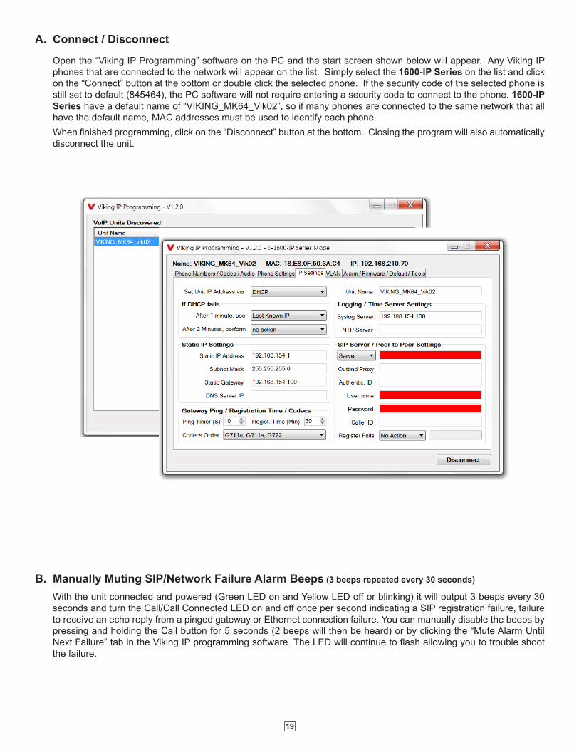
B. Manually Muting SIP/Network Failure Alarm Beeps (3 beeps repeated every 30 seconds)
With the unit connected and powered (Green LED on and Yellow LED off or blinking) it will output 3 beeps every 30 seconds and turn the Call/Call Connected LED on and off once per second indicating a SIP registration failure, failure to receive an echo reply from a pinged gateway or Ethernet connection failure. You can manually disable the beeps by pressing and holding the Call button for 5 seconds (2 beeps will then be heard) or by clicking the “Mute Alarm Until Next Failure” tab in the Viking IP programming software. The LED will continue to flash allowing you to trouble shoot the failure.
A. Connect / Disconnect
Open the “Viking IP Programming” software on the PC and the start screen shown below will appear. Any Viking IP phones that are connected to the network will appear on the list. Simply select the 1600-IP Series on the list and click on the “Connect” button at the bottom or double click the selected phone. If the security code of the selected phone is still set to default (845464), the PC software will not require entering a security code to connect to the phone. 1600-IP Series have a default name of “VIKING_MK64_Vik02”, so if many phones are connected to the same network that all have the default name, MAC addresses must be used to identify each phone. When finished programming, click on the “Disconnect” button at the bottom. Closing the program will also automatically disconnect the unit.
20
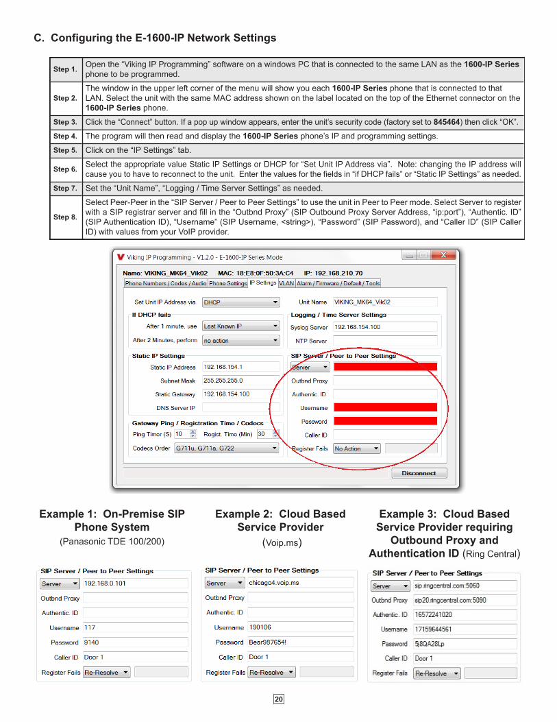
C. Configuring the E-1600-IP Network Settings
Step 1. Open the “Viking IP Programming” software on a windows PC that is connected to the same LAN as the 1600-IP Series phone to be programmed.
Step 2.The window in the upper left corner of the menu will show you each 1600-IP Series phone that is connected to that LAN. Select the unit with the same MAC address shown on the label located on the top of the Ethernet connector on the 1600-IP Series phone.
Step 3. Click the “Connect” button. If a pop up window appears, enter the unit’s security code (factory set to 845464) then click “OK”.Step 4. The program will then read and display the 1600-IP Series phone’s IP and programming settings.Step 5. Click on the “IP Settings” tab.
Step 6. Select the appropriate value Static IP Settings or DHCP for “Set Unit IP Address via”. Note: changing the IP address will cause you to have to reconnect to the unit. Enter the values for the fields in “if DHCP fails” or “Static IP Settings” as needed.
Step 7. Set the “Unit Name”, “Logging / Time Server Settings” as needed.
Step 8.
Select Peer-Peer in the “SIP Server / Peer to Peer Settings” to use the unit in Peer to Peer mode. Select Server to register with a SIP registrar server and fill in the “Outbnd Proxy” (SIP Outbound Proxy Server Address, “ip:port”), “Authentic. ID” (SIP Authentication ID), “Username” (SIP Username, <string>), “Password” (SIP Password), and “Caller ID” (SIP Caller ID) with values from your VoIP provider.
Example 2: Cloud Based Service Provider
(Voip.ms)
Example 3: Cloud Based Service Provider requiring
Outbound Proxy and Authentication ID (Ring Central)
Example 1: On-Premise SIP Phone System
(Panasonic TDE 100/200)

21
E. Manually Resetting the Security Code to Enter Programming
F. Manually Resetting All Network Parameters to Factory Default
Step 1. Power down the 1600-IP Series phone by disconnecting the LAN Cable (RJ45 plug).
Step 2. Press and hold the Call button, then reconnect the LAN Cable (RJ45 plug).
Step 3.Continue to hold t he Call button until you hear 2 beeps, (approximately 6 seconds). Continue to hold Call button until you hear 4 more beeps, approximately 6 seconds later, then release the button. The LED will remain off for the first 3 seconds, flash slowly for 3 seconds (2 beeps), fast flash for 6 seconds (4 beeps), then light steady indicating when to release button.
Step 4. You can now enter programming by following the steps in section A.
Step 1. Power down the 1600-IP Series phone by disconnecting the LAN Cable (RJ45 plug).
Step 2. Press and hold the Call button, then reconnect the LAN Cable (RJ45 plug).
Step 3. Continue to hold Call button until you hear 2 beeps, (approximately 6 seconds). Then release the button. The LED will remain off for the first 3 seconds, flash slowly for 3 seconds then fast flash (after 2 beeps), indicating when to release button.
Step 4. The security code is now reset to 845464 (factory default).
Step 5. You can now enter programming by following the steps in section A.
Step 1. Click on the “VLAN” tab
Step 2. Disable or enable VLAN tagging by setting the value of “VLAN Tagging”.
Step 3. Set the VLAN tag ID by selecting an integer (1 to 4094) in “ID for all packets”.
Step 4. Set the Priority Code Point (PCP) value for all not SIP and RTP packets in the “PCP for all packets” input (0 is default, priorities are from low to high: 0, 1, 2, 3, 4, 5, 6, 7). Set the “PCP for SIP packets” (3 is default). Set the “PCP for RTP packets” (5 is default).
D. Configuring E-1600-IP VLAN Settings

22
Programming Features Index
DESCRIPTION Section PageConnect/Disconnect A 19
VLAN Settings D 21
Unit Name 1 23
SIP Server 2 23
Peer to Peer Settings 3 23
Outbound Proxy 4 23
Authentication ID 5 23
Register Fails 6 23
Speed Dial Numbers 7 24
Security code (factory set to 845464) 8 24
ID Number 9 24
Access Code (1 - 6 digits, blank = disabled, factory set to 123456) 10 24
Audio File 11 24
Recording Emergency Announcement from a phone 12 24
Internal / External Relay (factory set to Internal) 13 25
Relay Mode (Door Strike, Outbound Call, Inbound / Outbound Call, Doorbell, LV-1K Control, Ring, Ring Flash, factory set to Outbound Call) 14 25
Relay Activation Command (1 or 2 digits, factory set to QQ) NOTE: Relay Mode must be set to Door Strike 15 26
Relay Activation Time (0.5 - 99 sec, factory set to 5 sec) 16 26
Relay Buzz Volume (1 - 3 or Disabled, factory set to 3) 17 26
Relay Latch Commands (Enabled or Disabled, factory set to Enabled) NOTE: Relay Mode must be set to Door Strike 18 26
Alternating Switch Action (factory set to Enabled) 19 26
Speaker Mode (ON, OFF / Silent Monitor or OFF until Answered, factory set to ON) 20 26
Speaker Volume (0 - 9, factory set to 3) 21 26
Ring Volume (0 - 9, factory set to 5) 22 26
Microphone Volume (0 - 9, 0 = Auto, factory set to 5) 23 27
Talk/Listen Delay (VOX) (0.1 - 0.9 seconds, factory set to 0.5 seconds) 24 27
In-Band Audio Call Progress (Enabled, Disabled, factory set to Enabled) 25 27
In-Band Audio Detect Sensitivity (1 - 9, 1 = minimum, 9 = maximum, factory set to 5, power cycle unit after setting) 26 27
Repeat Announcement Option (factory set to 1) 27 27
Lap Counter ( 1 - 9 or Disabled, factory set to Disabled) 28 27
Call Length Time Out (disabled or 1 - 9 minutes, factory set to 3 minutes) 29 27
Inbound Call Mode (Disabled, Auto Answer, Auto Answer-Secure, Ring, Ring with AGC, Factory set to Auto Answer) 30 28
Ring Cadence (factorty set to Normal Ring, 2 seconds on 4 seconds off) 31 28
Dial Next Number on RNA (Ring No Answer) (disabled, 1 - 9 = number of rings, factory set to 7) 32 28
Dial Next Number on Busy (disabled or enabled, factory set to enabled) 33 28
Send ID Numbers as (RFC 2833 or In Band DTMF, factory set to RFC 2833) 34 28
Call LED Mode (OFF, Entry Phone, Emergency Phone or Emergency Outbound only, factory set to Entry Phone) 35 29
Call LED Control (Automatic or enter Q to light, factory set to Automatic) 36 29
Mute Current / Next Alarm 37 29
Permanent Alarm Mute (factory set to Alarm Tones Enabled) 38 30
IP Firmware 39 30
Unit Firmware 40 30
Import/Export 41 30
Clear Phone Settings 42 30
Clear IP Settings 43 30
Diagnostics (used to check mic, speaker and relay operations) 44 30
23
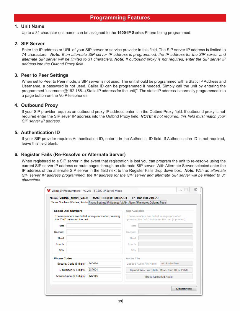
3. Peer to Peer SettingsWhen set to Peer to Peer mode, a SIP server is not used. The unit should be programmed with a Static IP Address and Username, a password is not used. Caller ID can be programmed if needed. Simply call the unit by entering the programmed “[email protected]...(Static IP address for the unit)”. The static IP address is normally programmed into a page button on the VoIP telephones.
6. Register Fails (Re-Resolve or Alternate Server)
4. Outbound Proxy If your SIP provider requires an outbound proxy IP address enter it in the Outbnd Proxy field. If outbound proxy is not required enter the SIP sever IP address into the Outbnd Proxy field. NOTE: If not required, this field must match your SIP server IP address.
5. Authentication IDIf your SIP provider requires Authentication ID, enter it in the Authentic. ID field. If Authentication ID is not required, leave this field blank.
2. SIP Server
1. Unit NameUp to a 31 character unit name can be assigned to the 1600-IP Series Phone being programmed.
Programming Features
When registered to a SIP server in the event that registration is lost you can program the unit to re-resolve using the current SIP server IP address or route pages through an alternate SIP server. With Alternate Server selected enter the IP address of the alternate SIP server in the field next to the Register Fails drop down box. Note: With an alternate SIP server IP address programmed, the IP address for the SIP server and alternate SIP server will be limited to 31 characters.
Enter the IP address or URL of your SIP server or service provider in this field. The SIP server IP address is limited to 74 characters. Note: If an alternate SIP server IP address is programmed, the IP address for the SIP server and alternate SIP server will be limited to 31 characters. Note: If outbound proxy is not required, enter the SIP server IP address into the Outbnd Proxy field.

24
7. Speed Dial Phone NumbersNote: Up to 90 digits can be stored in each of the 5 speed dial phone number positions. The number programmed in the first location under “Speed Dial Numbers” is the telephone or extension number that is dialed when the call button is pressed. Additional numbers (if programmed) will be dialed when there is no answer and the Dial Next No. on Ring No Answer feature is enabled. The 1600-IP Series Phone will also detect busy and move on (Dial Next Number on Busy Enabled). The 1600-IP Series Phone will cycle through the programmed Speed Dial numbers until answered.
The security code allows the user/installer to program the 1600-IP Series Phone. It is recommended that the factory set security code be changed. Factory Setting: 845464 Note: The security code must be 6 digits and cannot include a Q or a #.
Note: A majority of the features below can also be Touch Tone (In-Band DTMF) programmed, see DOD 949.
8. Security Code
The ID Number (1 - 6 digits) is used by emergency personnel to identify the location of the caller and is given out when the receiving party presses a Q. This ID number is transmitted as In-Band DTMF. This can be cleared out by leaving the field blank. Factory Setting: 987654
9. ID Number:
The Access Code is used for remotely operating the relay (Doorstrike, Mag-Lock, etc) by calling into the unit. This code provides basic security and only allows operation of the relays and not the ability to change any of the programming parameters. Once entered, any of the “Remote Access Operation Commands” can be used. The code can be 1 - 6 digits in length and cannot contain a “Q” or “#” or match the numbers used for the security code. Simply call the 1600-IP Series Phone (set to auto-answer/auto-answer secure), the unit will automatically answer the line and output one beep. You then enter the programmed 1 - 6 digit access code, 2 beeps should be heard. You can now enter any “Remote Access Operation Commands” (see page 19). This code will also enable audio to/from the speaker and the caller. The access code can be cleard (by leaving the field blank) if this additional level of security is not required. Factory Setting: 123456
10. Access Code
The 1600-IP Series Emergency Announcement can be uploaded with any user edited WAV file. See “WAV File Guidelines” below. Alternatively the announcement can be recorded via a telephone call (See section 12 below). WAV File Guidelines:
Note: Applications such as Sound Forge, Audacity, and Windows Sound Recorder can be used to create the WAV files.
11. Audio File (optional)
1. The WAV file should be 8 or 16 bit PCM mono or stereo.
2. Sampling rates of 8k,16k or 32kHz are acceptable.
3. The WAV file may be stereo or multi-channel, but only the Left Channel will be loaded.
4. When saved, wave files will be converted to 8KHz, mono, 16 bit, PCM.
5. The internal flash memory can hold up to 28 seconds of recorded audio.
Example: “Hudson Elementary School, classroom number 216 needs assistance. Press the star (Q) key on your telephone to hear this announcement again.”
12. Recording Emergency Announcement from a Phone
Step 1. Call into the 1600-IP Series with a Touch Tone phone and access programming by entering the security code (845464 is the factory default).
Step 2. Enter Q4, wait for the tone and then begin recording (28 seconds of record time is available).
Step 3. Enter # to stop the recording. Playback (for reviewing) is automatic.
Step 4. Enter Q5 to review the announcement again.
Step 5. If you choose to not use a voice announcement, enter Q 3 to clear the recording.

25
13. Relay Internal / ExternalWith the relay set to “Internal” the E-1600-IP Series Phone will activate its on board relay for door strike / gate control. The Relay should be set to “External” for higher security installations when using a Viking remote model RC-4A relay controller to activate the door strike / gate controller (see DOD 582). Factory Setting: Internal
14. Relay Mode Door Strike Mode. When programmed for Door Strike Mode the relay will momentarily activate for the preprogrammed relay activation time after detecting the correct relay activation command (one or two digit touch tone) from the called party.
Outbound Call Mode. When programmed for Outbound Call Mode the relay will activate continuously for the duration of any outbound call from the Emergency/Entry phone. This mode is useful for activating strobe lights for Emergency VoIP phones.
Inbound/Outbound Call Mode. When programmed for Inbound/Outbound Call Mode the relay will activate continuously for the duration of any inbound or outbound call to or from the Emergency/Entry phone. This mode is useful for turning on IR flood lights, VoIP phones with cameras, etc.
Doorbell Mode. When programmed for Doorbell Mode the relay will momentarily activate the relay for the preprogrammed relay activation time on any outbound call from the Emergency/Entry phone. This mode is useful for activating a door chime, etc. When activating door chimes, a 0.5 - 1 second relay activation time is recommended.
LV-1K Control Mode. When programmed for LV-1K Control Mode the relay will activate continuously while the Emergency/Entry phone is powered and registered to the SIP server. In the event the unit loses power and/or SIP registration the relay will turn off, activating LV-1K’s flashing LED and audible beep signals.
Ring Mode. When programmed for Ring Mode the relay will continuously activate while the ringing extension is called. This mode is useful for activating a Viking model SL-2 strobe light, etc.
Ring Flash Mode. When programmed for Ring Flash Mode the relay will momentarily turn on and off in a 400ms on/off cadence while the ringing extension is called. This mode is useful for activating a Viking LPL-1 Remote Visual Indicator, etc. Factory Setting: Outbound Call
26
When set to “Enabled” the Remote Access Operation Commands (Q0 to Q1) to Un-Latch or Latch the relay are enabled. These can be entered on a Inbound call after the access code is dialed (if programmed). When set to “Disabled” the Remote Access Operation Commands (Q0 to Q1) to Un-Latch or Latch the relay are disabled. Disabling the Latch commands can be useful in applications where you want to eliminate the possibility of inadvertently entering a latch command leaving a gate open/closed, etc. Factory Setting: Enabled
18. Relay Latch Commands
The Speaker volume can be set from 0 - 9, 0 = lowest volume setting, 9= highest volume setting. Adjusting this will set the volume level for incoming/outgoing Phone calls. Factory Setting: 3
21. Speaker Volume
20. Speaker Mode The Speaker Mode can be set to one of the following three modes. Factory Setting: ON OFF/Silent Monitoring Mode: In the “OFF” mode the speaker is disabled at all times. However, the speaker can be enabled after communication has been established by entering touch tone command “9#”. The speaker will remain on for the duration of the call. ON (factory setting): In the “ON” mode the speaker is enabled during In-bound and Out-bound calls. OFF Until Answered: In the “OFF Until Answered” mode the speaker will remain silent during dialing and will not turn on until the called party has answered.
With Alternate Switch Action Enabled the CALL button alternately connects and disconnects calls. With Alternate Switch Action Disabled the CALL button connects calls only. Pressing the button again after the call has been initiated will not terminate the call. Factory Setting: Enabled
19. Alternating Switch Action (Panic Button Mode)
When set to Ring or Ring with AGC, The 1600-IP Series Phone will output a loud ring when it is called. The level can be adjusted from 0 - 9. Factory Setting: 5
22. Ring Volume
The relay activation tone is a buzzing sound that is heard from the speaker when the door strike relay is activated. After the called party enters the correct relay activation command, the called party will hear 2 short confirmation beeps and the entry phone will output a buzzing sound (relay activation tone) while the door strike relay is activated. The tone (buzz) length will match the relay activation time up to a maximum of 5 seconds. The tone (buzz) can be programmed to three different volume settings 1 = Low, 2 = Medium, 3 = High or it can be disabled. Factory Setting: 3
17. Relay Buzz Volume
The one or two digit code stored in the Relay Activation Command is the touch tone command that the person being called must enter on their phone in order to momentarily activate the relay to control a doorstrike, mag-lock, gate controller, or other device. The code can contain the characters 0 - 9, # or Q. The code cannot match a relay latching command (Q1, Q0). The code must be entered while the remote phone is communicating with the Speaker phone. Factory Setting: QQ
15. Relay Activation Command
The value stored in the Relay Activation Time is the amount of time the relay will be energized after a correct momentary touch tone command is entered. This number can range from 0.5 - 99 seconds. This also affects timing in Doorbell Mode. Factory Setting: 5 seconds
16. Relay Activation Time

27
The In-Band Audio Detection level (Sensitivity) can be set from 1 - 9, 1 = minimum setting, 9 = highest setting. Increasing or decreasing the sensitivity may be required in applications where you are making an outbound call through your VoIP phone system and are relying on In-Band analog audio detection. Factory Setting: 5
26. In-Band Audio Detect Sensitivity
28. Lap Counter With the lap counter disabled, if the E-1600-IP Series Phone is programmed to dial the next number on ring-no-answer and/or busy signal, the E-1600-IP Series Phone will continuously call its programmed phone numbers forever until the call is answered.
The lap counter is a programmable counter that determines how many times the E-1600-IP Series Phone will cycle through its list of up to 5 Speed Dial phone numbers, before it stops the dialing process and hangs up. When all of the programmed phone numbers have been dialed, the lap counter is incremented and the dialing process repeats. When the lap counter has been met, the dialing process stops and the E-1600-IP Series Phone hangs up.
Factory Setting: Disabled
This feature selects the maximum length of time that calls can be connected. Programmable in increments of 1 minute up to a maximum of 9 minutes or disabled. With the call length disabled, the 1600-IP Series Phone must rely on a call ended signal, busy signal, Ring No Answer limit, or touch tone # to hang-up. Factory Setting: 3 minutes
29. Call Length Timeout
This feature selects switching time between talk and listen modes (VOX switching time). The Talk/Listen Delay can be programmed from 0.1 - 0.9 seconds. Factory Setting: 0.5 seconds
24. Talk / Listen Delay (VOX)
The In-Band Audio Call Progress Detection can be set to enabled or disabled. In-Band Audio Call Progress detection should be enabled in applications where you are making an outbound call through your VoIP phone system and are relying on In-Band analog audio for ringback or busy detection. Factory Setting: Enabled.
25. In-Band Audio Call Progress
27. Repeat Announcement Option The 1600-IP Series Phone can be programmed to play the announcement from 1 - 9 times, or to continuously repeat the announcement every 6 seconds until a Touch Tone Q is detected from the distant party. The call connected LED will turn on automatically after the announcement has stopped repeating. Factory Setting: 1 (play the announcement 1 time)
The microphone volume can be set from 1 to 9, 1 = lowest volume setting, 9 = highest volume setting. Alternatively the microphone can be placed in the “Auto” Automatic Noise Cancelling mode. With the mic in the Auto mode, when background noise increases, the mic gain will automatically decrease. When background noise decreases the mic gain will automatically increase. The Auto mode is useful in applications where the background noise level can change drastically. Factory Setting: 5
23. Microphone Volume / Automatic Noise Cancelling Mode
28
If enabled and a busy is detected, the speaker phone will dial the next programmed Speed Dial number. A momentary press of the call button will dial the first programmed phone number. Factory Setting: Enabled
33. Dial Next Number on Busy
34. Send ID Number as
32. Dial Next Number on Ring No AnswerIf enabled and a ring-no-answer is detected, the 1600-IP Series Phone will dial the next programmed Speed Dial number after the programmed amount of rings. A momentary press of the call button will dial the first programmed Speed Dial number. Factory Setting: 7 (will redial after 7 rings)
The I.D. number can be transmitted as RFC 2833 or as In-Band DTMF. Factory Setting: RFC 2833
31. Ring Cadence
The Ring cadence can be programmed to one of 4 different cadences. Factory Setting: Normal Ring Normal Ring (single ring, 2 seconds on 4 seconds off) factory setting Double Ring (double ring, 1 second on 0.5 seconds off 1 second on 3.5 seconds off) Short-Short-Long (triple ring, 0.5 seconds on 0.5 seconds off 0.5 seconds on 0.5 seconds off 1 second on 3 seconds off) Short-Long-Short (triple ring, 0.5 seconds on 0.5 seconds off 1 second on 0.5 seconds off 0.5 seconds on 3 seconds off)
The Inbound Call Mode determines how the 1600-IP Series Phone handles incoming SIP calls. One option is to generate a loud ring sound through the speaker. The 1600-IP Series Phone can also auto answer a SIP call to transmit a page, control the relay or listen to transmit audio from the microphone. The last option is the silent monitor mode, which allows callers to listen to the transmit audio from the microphone. The “secure” options for auto answer require the callers to dial the access code in order to transmit a page, activate the relay or activate the optional RC-4A relays. Factory Setting: Auto Answer
Disabled – Inbound SIP calls are not allowed.
Auto Answer – Inbound SIP calls are auto answered on the first ring. This can also be used for Silent Monitoring by changing the Speaker Mode to ‘OFF/Silent Monitor”, See page 26. For more security use the Auto Answer Secure Mode.
Auto Answer Secure – In the “Auto Answer - Secure” mode, the phone will automatically answer an incoming call on the first ring. The unit will then output 2 beeps but will not go into two-way voice mode. After the 2 beeps are heard, you will have 10 seconds to enter the pre-programmed 1 - 6 digit Access Code (see section 10 on page 24). When the correct code in entered, 2 beeps will be heard and the unit will enable the Two-Way Mode (mic and speaker audio). After the correct Access Code is entered, any of the “Remote Access Operation Commands” can be used (see Operation, section B on page 31). Note: If the wrong Access Code is entered or more than 10 seconds have elapsed, the phone will output 3 beeps and disconnect.
Ring: In the “Ring” mode the speaker phone will not automatically answer an incoming call but will output a loud ring signal out of the speaker in a 2 seconds on, 4 seconds off ring pattern. There are four available ring cadences.
Ring with AGC: In the “Ring with AGC” mode the speaker phone will not automatically answer an incoming call but will output a loud ring signal out of the speaker in a 2 seconds on, 4 seconds off ring pattern. The phone will automatically increase or decrease the ring volume based on background ambient noise. The call can then be answered by momentarily pressing the call button.
30. Inbound Call Mode

29
37. Mute Current / Next Alarm A network failure alarm will be indicated by providing 3 beeps every 30 seconds. A network failure indicates the unit is not registered to the SIP server or there is a communication failure with the gateway. The three beeps can be muted by clicking on “Mute Current / Next Alarm”. The Status LED will continue to flash to assist troubleshooting. The alarm beeps can also be permanently disabled. See Permanent Alarm Mute.
During outbound SIP calls the “CALL” LED can be programmed to light automatically when the called party has answered or only light after the called party has entered a touch tone “Q”. Factory Setting: Automatic
36. “Call” LED Control
35. Call LED Mode
The “Call” LED on the E-1600-IP Series can be programmed to one of four different modes. Factory Setting: Entry Phone OFF Mode: Useful for silent monitoring applications. In this mode the LED will not light during normal operation. It will only light (blink) if it cannot register with the programmed SIP server or while manually resetting all network parameters to factory default. Entry Phone Mode: The LED will remain ON in the idle state, turn off while button is pressed, blink during dialing, light steady when the call is answered, then turn OFF momentarily when the call is completed. Emergency Phone Mode: The LED will remain OFF in the idle state, blink during dialing, light steady when the call is connected, then turn OFF when the call is completed. Emergency Phone Outbound Only: On outbound calls, the LED will remain OFF in the idle state, blink during dialing, light steady when the call is connected, then turn OFF when the call is completed. On in-bound calls, the LED will remain off. This is useful for silent monitoring on inbound calls.

30
41. Import / ExportThe Import / Export feature is useful for backing up all the 1600-IP Series Phone’s programming or for importing programming when installing multiple units with a majority of the same programming.
Clicking on the “Clear Unit Settings” button in programming will reset all of the Programming Features back to their factory default settings. Note: This command will not change or reset your IP settings.
42. Clear Unit Settings
Clicking on the “Clear IP Settings” will reset all of the IP settings back to their factory default settings. This also clears paging Group settings and Addresses. Note: This will not effect any speaker or paging settings.
43. Clear IP Settings
44. DiagnosticsThe Diagnostics section in the Viking IP Programming can be used to test the functionality of the mic, speaker and the on-board relay. Note: This will not work when relay mode is set to external or Alarm.
39. IP Firmware
If new 1600-IP Series Phone firmware is available, after opening the programming software a pop window will come up asking you if you would like to update firmware. An alternative method of updating can be done by clicking the IP firmware “Update IP” button. You can then browse to the folder that contains the PIP file for updating the unit’s IP firmware. This method is typically only used when Viking Technical Support has sent you updated IP firmware.
38. Permanent Alarm Mute
Selecting “Alarm Tones Disabled” will mute all alarm tones indefinitely. To re-enable alarm tones select “Alarm Tones Enabled”. Factory Setting: Alarm Tones Enabled
40. Unit FirmwareIf new 1600-IP Series Phone firmware is available, after opening the programming software a pop up window will ask if you would like to update firmware. Another way to update is accomplished by clicking the Unit firmware “Update Unit” button. You can then browse to the folder that contains the HEX file for updating the unit’s firmware. This method is typically only used when Viking Technical Support has sent you updated firmware.

31
Troubleshooting
If the unit cannot register with the programmed SIP server, the LED will blink on and off every two seconds, and three error beeps will be heard every 30 seconds until communication is restored. This alerts a potential user of a problem with the device that will prevent an emergency phone call from being made.
You may silence the error beeps, per instance, by pressing and holding the HELP/CALL button for 5 seconds or by clicking the “Mute Alarm Until Next Failure” button in the Viking IP Programming Software (see section B on page 19). The error beeps automatically re-enable once the unit is registered, to alert of any new problems that arise.
Operation
A. “HELP” / “CALL” ButtonWhen the “HELP” / “CALL” button is pressed, the 1600-IP Series phone dials a pre-programmed telephone number. The Call Connected LED momentarily flashes during dialing. In the event the line is busy or there is a ring-no-answer, the unit can be programmed to call additional phone numbers.
The phone then cycles through up to 5 pre-programmed emergency numbers until the call is answered. When the call is answered, the digital voice announcer will automatically play to identify the location of the emergency call. The phones are factory programmed to play the announcement once, and then automatically light the “Call Connected” LED to show that handsfree communication to emergency personnel is established. The Q key will send the I.D. number (if programmed), and play the announcement again. The distant party will know the location of the emergency call by either the voice announcement or by decoding the touch tone I.D. number. Once the “Call Connected” LED is on, the # key can be used to force the phone to hang-up.
B. “INFO” Button (E-1600-20/22/52/53-IP)When the “INFO” button is pressed (1600-20/22/52/53-IP only), the phone goes off-hook and dials the first “INFO” phone number programmed. If a busy signal is detected or the call goes unanswered, the phone will cycle through all five “INFO” phone numbers until the call is answered or lap counter is met. When answered, handsfree communication is established. Note: The voice announcement is for Emergency/Help calls only and will not play on a call initiated from the “INFO” button.
C. Remote Access Operation Commands
Feature Tone Tone Command Description
Activate Relay
QQ or ___ ___ Momentarily activate relay (1 or 2 digits, factory set to QQ).
Un-Latch Relay Q0 Un-latch* (deactivate) the relay.
Latch Relay Q1 Latch* (continuously activate) the relay.
Disconnect # Disconnects or forces the emergency phone to hang up.Send ID and
Play Message Q Send I.D. number (if programmed) and plays the announcement.
* Note: Latching commands must be enabled (Q6) in programming.
The following commands can be entered after answering an inbound call from the emergency phone. The commands can also be entered on an outbound call to the emergency phone. After the emergency phone auto answers the call, two beeps will be heard. If the access code has been disabled, you can now enter the Remote Access Operation Commands below. If an Access code has been programmed, enter the Access code digits. With the correct code entered, two beeps will be heard and you can now enter the Remote Access Operation Commands below.

32
Related Products
New ASME A17.1-2010 code requires that “the two-way communications means within the (elevator) car shall include a means to verify operability of the LAN connection”. When your local municipality adopts this new ASME A17.1 code the LV-1K can be added to fulfill all requirements for visual and audible signaling when it is determined the LAN connection is not functioning. The LV-1K can be added to any new or existing Viking 1600-IP Series elevator emergency phone as a stand alone solution. The LV-1K continuously monitors for loss of PoE or communication with the server and will immediately provide an audible and visual indication when the LAN connection has been accidentally cut or disconnected. In accordance to ASME A17.1, the LV-1K is labeled “ELEVATOR COMMUNICATION FAILURE” in ¼” high red letters, and will sound an audible signal every 30 seconds and flash a red light when a loss of connection is detected. Authorized personnel can silence the audible signal with the included key switch. The LED will remain flashing until the fault is corrected.
Line Verification Panel with Key Switch
For more information, see DOD 246
The VE-3x5, VE-5x5, VE-6x7 and VE-5x10 add vandal and weather resistance, as well as versatility to many Viking products. The VE-Series backboxes are available in black fine texture powder painted steel or Marine Grade 316 stainless steel. The weather resistant boxes are designed to be surface mounted to a wall, post, single gang box, or a VE-GNP gooseneck pedestal. Note: The VE-3x5 is not compatible with the VE-GNP pedestals and is not available in stainless steel.
The VE-3x5 is designed to be used with the E-40-EWP or E-50-EWP Series entry phones. The VE-5x5 is designed to be used with the E-10A-EWP, E-30-EWP, E-30-PT-EWP, E-60-EWP, E-65-EWP, E-70-EWP, E-75-EWP entry phones, the E-1600-20A-EWP, E-1600-20-IP-EWP, E-1600-30A-EWP and E-1600-30-IP-EWP emergency phones, as well as the W-1000-EWP and W-3000-EWP handsfree doorboxes. The VE-6x7 is designed to be used with the K-1700-3-EWP and K-1705-EWP entry phones and the VE-5x10 is designed to be used with the K-1900-7-EWP and the K-1900-8-EWP vandal resistant phones.
The VE-GNP gooseneck pedestals are designed to be used with the VE-5x5, VE-6x7 and VE-5x10 backboxes and are ideal for drive up communications. Note: The VE-3x5 is not compatible with the VE-GNP pedestals. The VE-PNL’s are VE-Series backboxes with a blank aluminum panel. The user can customize the clear-coated aluminum panel to mount an PRX-1 card reader, PRX-2 keypad or switch. The kits come complete with box, gasket, panel and screws. Model numbers that end with “SS” are stainless steel version. Note: The use of magnets to mount the VE-Series enclosure to a metal surface can affect the operation of the enclosed product.
VE-3x5 VE-5x5
VE-5x10VE-5x10-NR
VE-5x10-SS-NR
VE-5x5-PNL-SS
VE-6x7-PNL-SSVE-6x7-PNLVE-6x7-SSVE-6x7
VE-5x10-PNL-SSVE-5x10-SS
VE-5x5-SSVE-5x5-RD
VE-5x10-PNL
VE-5x5-PNL
VE-G
NP-
2
VE-G
NP-
IG
VE-G
NP-
SS
VE-G
NP
For more information, see DOD 424
Surface or Pedestal Mount Viking Products While Maintaining Weather and Vandal Resistance

33
Viking Area of Refuge Signs Designed to Comply with IBC, ADA, NFPA and ICC Requirements
The ARS Series Area of Refuge Signs are designed comply with IBC 1007,1011, ADA 4.3.11, NFPA 22, 101 and ICC 703 code requirements. The ARS-LR100 is an LED Illuminated edge-lit double sided hanging Sign. It is AC powered with 3 hour battery backup. The unit can be ceiling mounted, mounted flat against a wall or end mounted so it can be viewed from either direction. The Instructional, Tactile and Directional signs are made from Acrylic or durable ABS plastic and are designed to adhere to the wall with the provided double sided foam tape. For more information, see DOD 235.
ARS-TB100 Tactile Blue Braille and raised letter sign to be
placed next to the Area Of Refuge (stairwell exit) door.
ARS-IB100 Instructional Blue Braille and
Raised letter sign to be placed next to the Area of Refuge emergency
phone (E-1600A-IP, etc.)
ARS-LR100 Lighted double sided Wall or ceiling mount sign to be placed above the Area Of Refuge (stairwell exit) door.
Directional Blue signs with left or right arrow to be placed next to
exit doors without Area Of Refuge.
ARS-DLB100
ARS-DRB100
• ARS-LR100: Red LED edge lit wall sign, 120/277V AC power, Included NiCad battery delivers over 3 hours of battery backup, UL listed, Universal wall, side or ceiling mounting, Silver aluminum housing with mirrored double sided acrylic sign surface, Battery test button, AC pwr LED, Low voltage automatic battery disconnect to prevent deep cycling battery, mounting hardware and 4 optional Chevron arrows with mounting templates included.
• ARS-TB100: 6” wide x 9” tall Tactile Sign with 0.031” raised white letters and accesability symbol, California compliant Contrated Grade 2 Braille. Blue PMS 300 Acrylic with non-glare finish, 0.032” thick double sided foam included.
• ARS-IB100: 6” wide x 7.5” tall Instructional sign with 0.031” raised white “Push For Help” letters and ingraved white text, California compliant Contrated Grade 2 Braille. Blue PMS 294 ABS with non-glare finish, 0.032” thick double sided foam included.
• ARS-DLB100 (left arrow) and ARS-DRB100 (right arrow): 12” wide x 4” tall Directional sign with ingraved white text, Blue PMS 294 ABS with non-glare finish, 0.032” thick double sided foam included.
• VE-ARSW: Area of Refuge surface mount command center cabinet. Lockable for mounting “Two-Way Communications System” phone in low rise (less than 60 ft tall) buildings. See DOD 237.
Emergency Phone Panic Button Kit (for use with Viking Emergency Phones)
The PB-1 Panic Button Kit connects to a Viking 1600A or 1600-IP Series Emergency Phone to provide a one-way talk path to the pre-programmed number when used.
The PB-1 will activate the 1600A or 1600-IP Series Emergency Phone and allows the called party to light a red LED to indicate that the call is connected. The called party will be able to hear the installation site, but the site will not be able to hear the called party. This makes it a very effective security measure, as there is no other indication that the site is being monitored.
For more information, see DOD 233

34Printed in the U.S.A ZF303600 REV D
Due to the dynamic nature of the product design, the information contained in this document is subject to change without notice. Viking Electronics, and its affiliates and/or subsidiaries assume no responsibility for errors and omissions contained in this information. Revisions of this document or new editions of it may be issued to incorporate such changes.
DOD 255
Product Support: 715-386-8666
Warranty
IF YOU HAVE A PROBLEM WITH A VIKING PRODUCT, CONTACT VIKING TECHNICAL SUPPORT: 715-386-8666 Our Technical Support Department is available for assistance Monday through Friday 8:00am to 5:00pm central time. Before you call, please: 1. Know the model number, the serial number and what software version you have (see serial label). 2. Have the Product Manual in front of you. 3. It is best if you are on site.
TWO YEAR LIMITED WARRANTY Viking warrants its products to be free from defects in the workmanship or materials, under normal use and service, for a period of two years from the date of purchase from any authorized Viking distributor. If at any time during the warranty period, the product is deemed defective or malfunctions, return the product to Viking Electronics, Inc., 1531 Industrial Street, Hudson, WI., 54016. Customer must contact Viking's Technical Support Department at 715-386-8666 to obtain a Return Authorization (R.A.) number. This warranty does not cover any damage to the product due to lightning, over voltage, under age, accident, misuse, abuse, negligence or any damage caused by use of the product by the purchaser or others. This warranty does not cover non-EWP products that have been exposed to wet or corrosive environments. This warranty does not cover stainless steel surfaces that have not been properly maintained. NO OTHER WARRANTIES. VIKING MAKES NO WARRANTIES RELATING TO ITS PRODUCTS OTHER THAN AS DESCRIBED ABOVE AND DISCLAIMS ANY EXPRESS OR IMPLIED WARRANTIES OR MERCHANTABILITY OR FITNESS FOR ANY PARTICULAR PURPOSE. EXCLUSION OF CONSEQUENTIAL DAMAGES. VIKING SHALL NOT, UNDER ANY CIRCUMSTANCES, BE LIABLE TO PURCHASER, OR ANY OTHER PARTY, FOR CONSEQUENTIAL, INCIDENTAL, SPECIAL OR EXEMPLARY DAMAGES ARISING OUT OF OR RELATED TO THE SALE OR USE OF THE PRODUCT SOLD HEREUNDER. EXCLUSIVE REMEDY AND LIMITATION OF LIABILITY. WHETHER IN AN ACTION BASED ON CONTRACT, TORT (INCLUDING NEGLIGENCE OR STRICT LIABILITY) OR ANY OTHER LEGAL THEORY, ANY LIABILITY OF VIKING SHALL BE LIMITED TO REPAIR OR REPLACEMENT OF THE PRODUCT, OR AT VIKING'S OPTION, REFUND OF THE PURCHASE PRICE AS THE EXCLUSIVE REMEDY AND ANY LIABILITY OF VIKING SHALL BE SO LIMITED. IT IS EXPRESSLY UNDERSTOOD AND AGREED THAT EACH AND EVERY PROVISION OF THIS AGREEMENT WHICH PROVIDES FOR DISCLAIMER OF WARRANTIES, EXCLUSION OF CONSEQUENTIAL DAMAGES, AND EXCLUSIVE REMEDY AND LIMITATION OF LIABILITY, ARE SEVERABLE FROM ANY OTHER PROVISION AND EACH PROVISION IS A SEPARABLE AND INDEPENDENT ELEMENT OF RISK ALLOCATION AND IS INTENDED TO BE ENFORCED AS SUCH.
If trouble is experienced with the 1600-IP Series phone, for repair or warranty information, please contact: Viking Electronics, Inc., 1531 Industrial Street, Hudson, WI 54016 Phone: 715-386-8666
WHEN PROGRAMMING EMERGENCY NUMBERS AND (OR) MAKING TEST CALLS TO EMERGENCY NUMBERS: Remain on the line and briefly explain to the dispatcher the reason for the call. Perform such tests in off-peak hours, such as early morning or late evenings.
PART 15 LIMITATIONS This equipment has been tested and found to comply with the limits for a Class A digital device, pursuant to Part 15 of the FCC Rules. These limits are designed to provide reasonable protection against harmful interference when the equipment is operated in a commercial environment. This equipment generates, uses, and can radiate radio frequency energy and, if not installed and used in accordance with the instruction manual, may cause harmful interference to radio communications. Operation of this equipment in a residential area is likely to cause harmful interference in which case the user will be required to correct the interference at his own expense.
CANADA This class A digital apparatus complies with Canadian ICES-003. Cet appareil numerique de la classe A est conforme a la norme NMB-003 du Canada.
RETURNING PRODUCT FOR EXCHANGE The following procedure is for equipment that has failed out-of-box (within 10 days of purchase): 1. Customer must contact Viking’s Technical Support at 715-386-8666 to
determine possible causes for the problem. The customer MUST be able to step through recommended tests for diagnosis.
2. If the Technical Support Product Specialist determines that the equipment is defective based on the customer's input and troubleshooting, a Return Authorization (RA) number will be issued. This number is valid for fourteen (14) calendar days from the date of issue.
3. After obtaining the RA number, return the approved equipment to your distributor. Please reference the RA number on the paperwork being shipped back with the unit(s), and also the outside of the shipping box. The original product boxes are not designed for shipping - an overpack box is required to prevent damage in transit. Once your distributor receives the package, they will replace the product over the counter at no charge. The distributor will then return the product to Viking using the same RA number.
4. The distributor will NOT exchange this product without first obtaining the RA number from you. If you haven't followed the steps listed in 1, 2 and 3, be aware that you will have to pay a restocking charge.
RETURNING PRODUCT FOR REPAIR
The following procedure is for equipment that needs repair:
1. Customer must contact Viking's Technical Support Department at 715-386-8666 to obtain a Return Authorization (RA) number. The customer MUST have a complete description of the problem, with all pertinent information regarding the defect, such as options set, conditions, symptoms, methods to duplicate problem, frequency of failure, etc.
2. Packing: Return equipment in original box or in proper packing so that damage will not occur while in transit. The original product boxes are not designed for shipping - an overpack box is required to prevent damage in transit. Static sensitive equipment such as a circuit board should be in an anti-static bag, sandwiched between foam and individually boxed. All equipment should be wrapped to avoid packing material lodging in or sticking to the equipment. Include ALL parts of the equipment. C.O.D. or freight collect shipments cannot be accepted. Ship cartons prepaid to: VIKING ELECTRONICS
1531 INDUSTRIAL STREET HUDSON, WI 54016
3. Return shipping address: Be sure to include your return shipping address inside the box. We cannot ship to a PO Box.
4. RA number on carton: In large printing, write the RA number on the outside of each carton being returned.