16-FOOT HIGH-SPEED TUNNEL (16-Foot HST) 16 …_HST_Draft_1.pdf16-FOOT HIGH-SPEED TUNNEL (16-Foot...
15
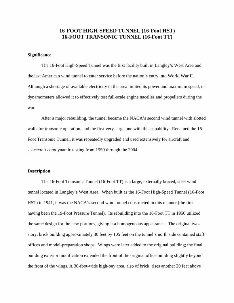
16-FOOT HIGH-SPEED TUNNEL (16-Foot HST) 16-FOOT TRANSONIC TUNNEL (16-Foot TT) Significance The 16-Foot High-Speed Tunnel was the first facility built in Langley’s West Area and the last American wind tunnel to enter service before the nation’s entry into World War II. Although a shortage of available electricity in the area limited its power and maximum speed, its dynamometers allowed it to effectively test full-scale engine nacelles and propellers during the war. After a major rebuilding, the tunnel became the NACA’s second wind tunnel with slotted walls for transonic operation, and the first very-large one with this capability. Renamed the 16- Foot Transonic Tunnel, it was repeatedly upgraded and used extensively for aircraft and spacecraft aerodynamic testing from 1950 through the 2004. Description The 16-Foot Transonic Tunnel (16-Foot TT) is a large, externally braced, steel wind tunnel located in Langley’s West Area. When built as the 16-Foot High-Speed Tunnel (16-Foot HST) in 1941, it was the NACA’s second wind tunnel constructed in this manner (the first having been the 19-Foot Pressure Tunnel). Its rebuilding into the 16-Foot TT in 1950 utilized the same design for the new portions, giving it a homogeneous appearance. The original two- story, brick building approximately 30 feet by 105 feet on the tunnel’s north side contained staff offices and model-preparation shops. Wings were later added to the original building; the final building exterior modification extended the front of the original office building slightly beyond the front of the wings. A 30-foot-wide high-bay area, also of brick, rises another 20 feet above
Transcript of 16-FOOT HIGH-SPEED TUNNEL (16-Foot HST) 16 …_HST_Draft_1.pdf16-FOOT HIGH-SPEED TUNNEL (16-Foot...
16-FOOT HIGH-SPEED TUNNEL (16-Foot HST) 16-FOOT TRANSONIC TUNNEL (16-Foot TT)
Significance
The 16-Foot High-Speed Tunnel was the first facility built in Langley’s West Area and
the last American wind tunnel to enter service before the nation’s entry into World War II.
Although a shortage of available electricity in the area limited its power and maximum speed, its
dynamometers allowed it to effectively test full-scale engine nacelles and propellers during the
war.
After a major rebuilding, the tunnel became the NACA’s second wind tunnel with slotted
walls for transonic operation, and the first very-large one with this capability. Renamed the 16-
Foot Transonic Tunnel, it was repeatedly upgraded and used extensively for aircraft and
spacecraft aerodynamic testing from 1950 through the 2004.
Description
The 16-Foot Transonic Tunnel (16-Foot TT) is a large, externally braced, steel wind
tunnel located in Langley’s West Area. When built as the 16-Foot High-Speed Tunnel (16-Foot
HST) in 1941, it was the NACA’s second wind tunnel constructed in this manner (the first
having been the 19-Foot Pressure Tunnel). Its rebuilding into the 16-Foot TT in 1950 utilized
the same design for the new portions, giving it a homogeneous appearance. The original two-
story, brick building approximately 30 feet by 105 feet on the tunnel’s north side contained staff
offices and model-preparation shops. Wings were later added to the original building; the final
building exterior modification extended the front of the original office building slightly beyond
the front of the wings. A 30-foot-wide high-bay area, also of brick, rises another 20 feet above
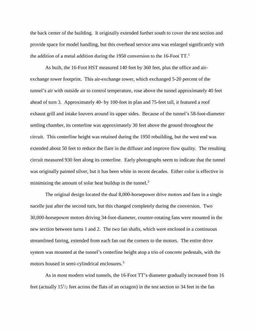
the back center of the building. It originally extended further south to cover the test section and
provide space for model handling, but this overhead service area was enlarged significantly with
the addition of a metal addition during the 1950 conversion to the 16-Foot TT.1
As built, the 16-Foot HST measured 140 feet by 360 feet, plus the office and air-
exchange tower footprint. This air-exchange tower, which exchanged 5-20 percent of the
tunnel’s air with outside air to control temperature, rose above the tunnel approximately 40 feet
ahead of turn 3. Approximately 40- by 100-feet in plan and 75-feet tall, it featured a roof
exhaust grill and intake louvers around its upper sides. Because of the tunnel’s 58-foot-diameter
settling chamber, its centerline was approximately 30 feet above the ground throughout the
circuit. This centerline height was retained during the 1950 rebuilding, but the west end was
extended about 50 feet to reduce the flare in the diffuser and improve flow quality. The resulting
circuit measured 930 feet along its centerline. Early photographs seem to indicate that the tunnel
was originally painted silver, but it has been white in recent decades. Either color is effective in
minimizing the amount of solar heat buildup in the tunnel.2
The original design located the dual 8,000-horsepower drive motors and fans in a single
nacelle just after the second turn, but this changed completely during the conversion. Two
30,000-horsepower motors driving 34-foot-diameter, counter-rotating fans were mounted in the
new section between turns 1 and 2. The two fan shafts, which were enclosed in a continuous
streamlined fairing, extended from each fan out the corners to the motors. The entire drive
system was mounted at the tunnel’s centerline height atop a trio of concrete pedestals, with the
motors housed in semi-cylindrical enclosures.3
As in most modern wind tunnels, the 16-Foot TT’s diameter gradually increased from 16
feet (actually 151/2 feet across the flats of an octagon) in the test section to 34 feet in the fan
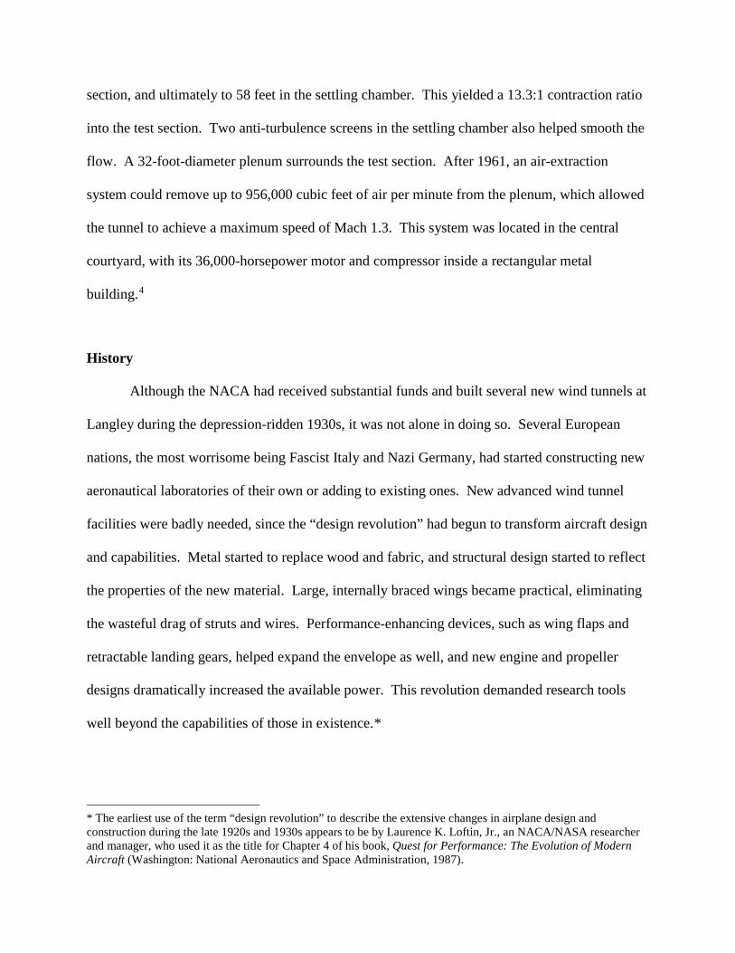
section, and ultimately to 58 feet in the settling chamber. This yielded a 13.3:1 contraction ratio
into the test section. Two anti-turbulence screens in the settling chamber also helped smooth the
flow. A 32-foot-diameter plenum surrounds the test section. After 1961, an air-extraction
system could remove up to 956,000 cubic feet of air per minute from the plenum, which allowed
the tunnel to achieve a maximum speed of Mach 1.3. This system was located in the central
courtyard, with its 36,000-horsepower motor and compressor inside a rectangular metal
building.4
History
Although the NACA had received substantial funds and built several new wind tunnels at
Langley during the depression-ridden 1930s, it was not alone in doing so. Several European
nations, the most worrisome being Fascist Italy and Nazi Germany, had started constructing new
aeronautical laboratories of their own or adding to existing ones. New advanced wind tunnel
facilities were badly needed, since the “design revolution” had begun to transform aircraft design
and capabilities. Metal started to replace wood and fabric, and structural design started to reflect
the properties of the new material. Large, internally braced wings became practical, eliminating
the wasteful drag of struts and wires. Performance-enhancing devices, such as wing flaps and
retractable landing gears, helped expand the envelope as well, and new engine and propeller
designs dramatically increased the available power. This revolution demanded research tools
well beyond the capabilities of those in existence.*
* The earliest use of the term “design revolution” to describe the extensive changes in airplane design and construction during the late 1920s and 1930s appears to be by Laurence K. Loftin, Jr., an NACA/NASA researcher and manager, who used it as the title for Chapter 4 of his book, Quest for Performance: The Evolution of Modern Aircraft (Washington: National Aeronautics and Space Administration, 1987).
For a time, these European nations substantially outbuilt the United States, but the NACA
kept watch on their activities through its Paris office, manned by John Jay Ide. Ide visited most
of these new facilities and submitted detailed reports to NACA Director of Aeronautical
Research George Lewis. Concerned over Ide’s reports, Lewis visited Europe to see for himself
in 1936. Although an isolationist Congress was slow to act, the NACA finally secured $11
million for a major expansion in 1939. The largest portion of these funds allowed the NACA to
begin construction of a new West Coast laboratory, named the Ames Aeronautical Laboratory in
1940, but a $1.5 million appropriation initiated a major change in the look and capability of the
Langley Laboratory as well.5
Both Ames and Langley soon began to build 16-foot high-speed tunnels. They were
quite similar, except for power. Once again, the shortage of power in Hampton limited the
Langley 16-Foot High-Speed Tunnel (16-Foot HST) to 16,000 horsepower and, thus, about
Mach 0.7. (While substantial, this was less than 60 percent of the power installed in its
counterpart at Ames.) The Langley tunnel was authorized a few months before the one at Ames,
but construction proceeded at a slightly slower pace, so it entered service a few weeks later. One
of the reasons is that the 16-Foot HST broke new ground—quite literally—at Langley. Between
expansions of both NACA and Army Air Corps facilities, there simply was little room left for a
new wind tunnel on the east side of Langley Field, so the NACA looked west to find room on the
other side of the field. The 16-Foot HST was a large machine, and it became the first tunnel
built in the West Area. It was also the last wind tunnel to go on-line in 1941, opening only two
days before the Japanese attack on Pearl Harbor.6
Knowing that electrical power was in short supply, David J. Biermann and Lindsey I.
Turner, Jr., the lead design engineers, had developed the rationale for the 16-Foot HST carefully.
Clearly it would not be useful for the most advanced aerodynamical studies—the Ames tunnel
was for that—but the 16-foot size would be perfect to investigate engine-cooling problems.
Years earlier, the NACA cowling had vastly improved the cooling of air-cooled radial engines
and lowered drag as well. By the late-1930s, these early single-row radial engines had grown
into two-row models, and cooling the second row of cylinders emerged as a major problem, one
that no existing wind tunnel had both the size and speed to help solve.7
Propeller research was another serious need, particularly to determine the optimal settings
for variable-pitch propellers under various conditions. Variable-pitch propellers had been
developed during the 1930s, but much remained to be learned about how they could best be used
throughout the flight envelope. The 16-Foot HST’s power would allow it to cover the entire
speed range of propeller-driven planes and make it ideal for propeller investigations.
With these goals in mind, Biermann and Turner’s team designed a closed-circuit,
atmospheric tunnel with an air-exchange tower that would maintain reasonable temperatures in
the tunnel as well as replace a significant portion of engine exhaust gas with fresh air during
operation. They chose to use a design similar to one pioneered by the Wright Brothers Wind
Tunnel in 1938 at the Massachusetts Institute of Technology and employed in Langley’s 19-Foot
Pressure Tunnel a year later. While the 16-Foot HST would not be pressurized like these two
tunnels, its large size made the externally braced, steel-shell design the best choice for strength
and economy. Equipped with 2,000- and 6,000-horsepower electric dynamometers, the tunnel
could operate full-sized propellers at airspeeds up to around 500 miles per hour. The
dynamometers provided accurate measurements of the amount of power a given propeller could
efficiently handle, and helped determine its optimum operating conditions (revolutions per
minute and pitch angle) for a variety of flight conditions.
Tests of two-row radial engines engine running at flight airflows with thermocouples
mounted to measure the temperatures at critical spots helped engineers design and adjust internal
baffles to alter the airflow and better cool hot areas. These tests proved difficult, however, due to
choking in the tunnel around Mach 0.6, and they were discontinued in 1943, after the Lewis
Flight Propulsion Laboratory in Cleveland opened with facilities better suited to the task.8
While not state of the art in speed, the 16-Foot HST was well engineered and suited to its
wartime mission. After World War II, however, transonic (generally defined as being between
Mach 0.7 to 1.2) research suddenly became a top priority with the advent of jet engine powered
aircraft. As discussed in the 8-Foot High-Speed Tunnel section, choking problems prevented
stable wind-tunnel operation near the speed of sound until Langley’s Ray Wright developed a
practical slotted-wall design in 1950. By that time, the NACA had decided to rebuild the 16-
Foot HST with more power, so Section Chief John Stack included a new, slotted-wall test
section in the rebuilding project.
The 16-Foot HST’s position as the first facility in Langley’s West Area plus its looming
role in post-war transonic research uniquely suited it to serve as host for no fewer than five small
tunnels built to inexpensively try out new concepts for trans- and supersonic research. Such
parasitic tunnels that utilized the power, support facilities, and staffs of their hosts were not
uncommon at Langley, and several have already been noted, but the number and variety
supported by the 16-Foot TT during the late 1940s is unusual. Since these tunnels were often
“proof-of-concept” devices, research work done in them rarely warranted technical papers, nor
did the NACA publish descriptive publications. Thus, comparatively little is now known about
them, but one memorandum answering an inquiry about Langley’s supersonic facilities at least
furnishes some basic information: 9
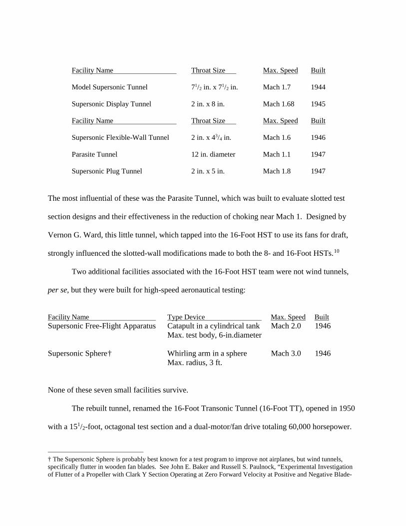
Facility Name Throat Size Max. Speed Built
Model Supersonic Tunnel 71/2 in. x 71/2 in. Mach 1.7 1944
Supersonic Display Tunnel 2 in. x 8 in. Mach 1.68 1945
Facility Name Throat Size Max. Speed Built Supersonic Flexible-Wall Tunnel 2 in. x 43/4 in. Mach 1.6 1946
Parasite Tunnel 12 in. diameter Mach 1.1 1947
Supersonic Plug Tunnel 2 in. x 5 in. Mach 1.8 1947
The most influential of these was the Parasite Tunnel, which was built to evaluate slotted test
section designs and their effectiveness in the reduction of choking near Mach 1. Designed by
Vernon G. Ward, this little tunnel, which tapped into the 16-Foot HST to use its fans for draft,
strongly influenced the slotted-wall modifications made to both the 8- and 16-Foot HSTs.10
Two additional facilities associated with the 16-Foot HST team were not wind tunnels,
per se, but they were built for high-speed aeronautical testing:
Facility Name Type Device Max. Speed Built Supersonic Free-Flight Apparatus Catapult in a cylindrical tank Mach 2.0 1946
Max. test body, 6-in.diameter Supersonic Sphere† Whirling arm in a sphere Mach 3.0 1946 Max. radius, 3 ft.
None of these seven small facilities survive.
The rebuilt tunnel, renamed the 16-Foot Transonic Tunnel (16-Foot TT), opened in 1950
with a 151/2-foot, octagonal test section and a dual-motor/fan drive totaling 60,000 horsepower.
† The Supersonic Sphere is probably best known for a test program to improve not airplanes, but wind tunnels, specifically flutter in wooden fan blades. See John E. Baker and Russell S. Paulnock, “Experimental Investigation of Flutter of a Propeller with Clark Y Section Operating at Zero Forward Velocity at Positive and Negative Blade-
The new motors and fans were mounted on massive concrete pedestals with the motors outside
the tunnel and the counter-rotating fans relocated between the first and second corners. The
tunnel’s west end was also lengthened to provide a longer diffuser to improve flow quality
leading in to the fan drive section. The slots were placed at the intersections of the test section
wall panels, and a large plenum was erected around it, along with a 6-story-high metal service
building. The upper three test section panels and the top of the plenum opened to allow insertion
of test items. Several model mounts were provided, including a sting and sidewall supports. A
hydrogen peroxide system enabled hot exhaust simulation in models of jet engines and aircraft.11
Researchers rapidly booked the 16-Foot TT with a wide variety of test programs,
particularly programs involving jet engine inlets and exhausts, and their interactions with the
airframes. Engineers learned much about how the design of these components affected the
performance of both engines and aircraft.
When opened in 1950, the 16-Foot TT could reach a maximum speed of Mach 1.08, but
researchers discovered that measurements above Mach 1.03 were inaccurate, due to wall
reflected shock waves from the model nose. The slotted wall design was not perfect and model
blockage effects tended to become significant at high subsonic Mach numbers. During the
1950s, studies indicated that air removal from the plenum and test section could help reduce
model blockage effects, and the newly created NASA approved the addition of an air removal
system. Installed in 1961, an axial-flow compressor driven by a 36,000-horsepower motor
extracted up to 956, 000 cubic feet of air per minute—approximately 4.5 percent of the tunnel’s
total flow—from the plenum. This served to reduce model blockage effects near Mach = 1 and
the total energy needed for the main drive to overcome both shock and diffuser losses. The net
effect raised the maximum stable speed to Mach 1.3 at a lower cost than increasing the main
Angle Settings,” Technical Note 1966 (Washington: National Advisory Committee for Aeronautics, 1949).
drive power.12 The higher speed capability allowed models of up to 6 feet long to be tested
without reflected shock interactions at speeds above approximately Mach 1.15.
Further changes to the 16-Foot TT included the addition of improved tunnel controls,
new sitka spruce fan blades, and an on-site data-acquisition system in 1977. These features were
again upgraded in 1989-91 to keep the tunnel up to date.13
Changes to the 16-Foot TT over the years revealed that the original slot shape selected in
1950 needed further refinement to obtain optimal performance. This was especially true after the
addition of the plenum air extraction system raised the top speed. Theory provided some initial
guidance to these studies, but most of the refinement was an empirical process. No less than 11
different shapes were tried before one known as “slot shape 29“ proved suitable for speeds up to
Mach 1.3.14
Changes in the nature of aeronautical research, including the growth of computerized
fluid dynamics (CFD), coupled with an overall reduction in the number of advanced aircraft
programs, gradually reduced the tunnel’s workload during the 1990s. This, coupled with budget
constraints and the availability of other tunnels with similar capabilities, led NASA to close the
16-Foot TT in 2004. While it currently remains in place, NASA hopes to demolish it in the near
future.15
Illustrations
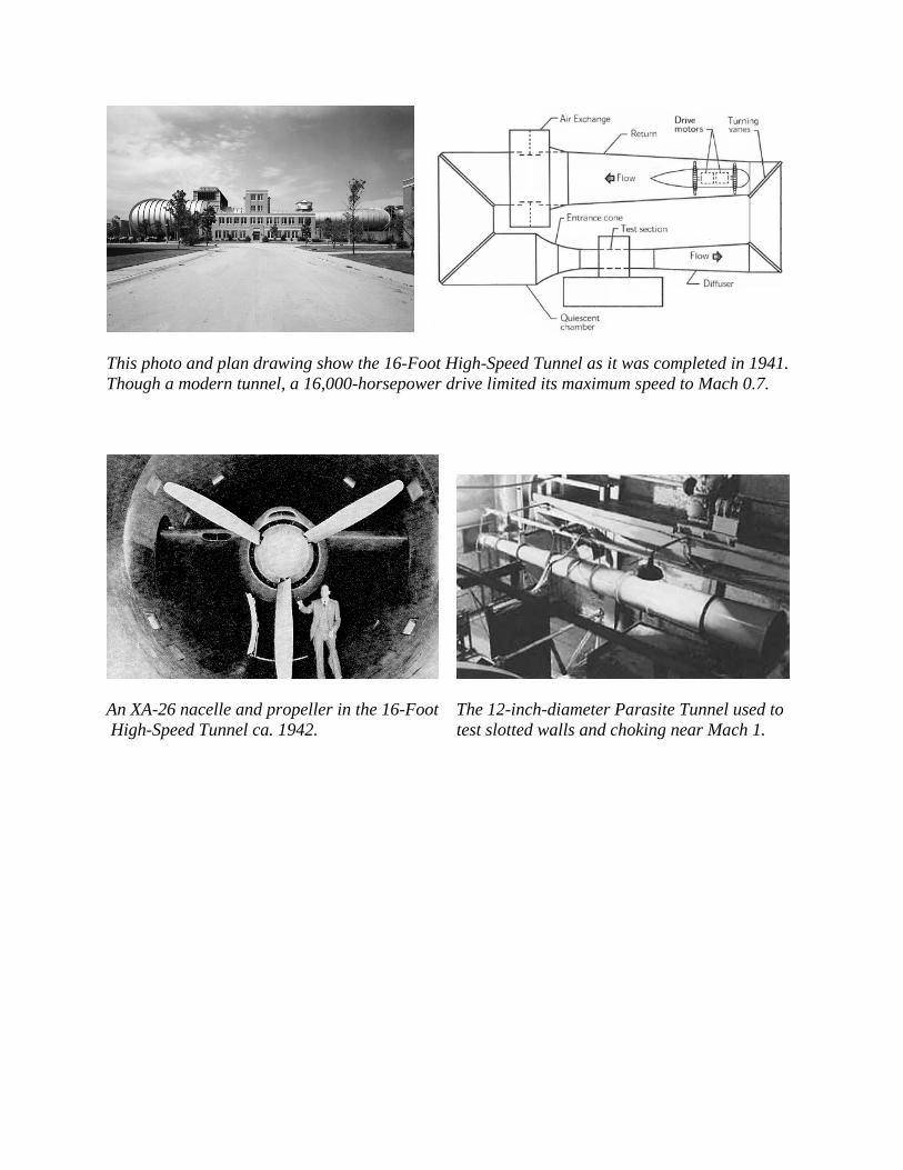
This photo and plan drawing show the 16-Foot High-Speed Tunnel as it was completed in 1941. Though a modern tunnel, a 16,000-horsepower drive limited its maximum speed to Mach 0.7.
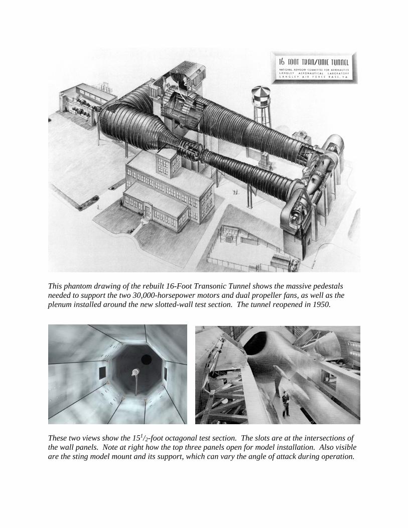
An XA-26 nacelle and propeller in the 16-Foot The 12-inch-diameter Parasite Tunnel used to High-Speed Tunnel ca. 1942. test slotted walls and choking near Mach 1.
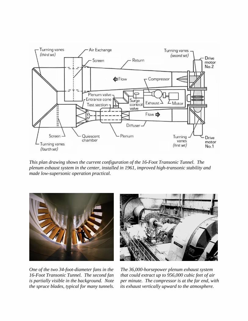
This phantom drawing of the rebuilt 16-Foot Transonic Tunnel shows the massive pedestals needed to support the two 30,000-horsepower motors and dual propeller fans, as well as the plenum installed around the new slotted-wall test section. The tunnel reopened in 1950.
These two views show the 151/2-foot octagonal test section. The slots are at the intersections of the wall panels. Note at right how the top three panels open for model installation. Also visible are the sting model mount and its support, which can vary the angle of attack during operation.
This plan drawing shows the current configuration of the 16-Foot Transonic Tunnel. The plenum exhaust system in the center, installed in 1961, improved high-transonic stability and made low-supersonic operation practical.
One of the two 34-foot-diameter fans in the The 36,000-horsepower plenum exhaust system 16-Foot Transonic Tunnel. The second fan that could extract up to 956,000 cubic feet of air is partially visible in the background. Note per minute. The compressor is at the far end, with the spruce blades, typical for many tunnels. its exhaust vertically upward to the atmosphere.
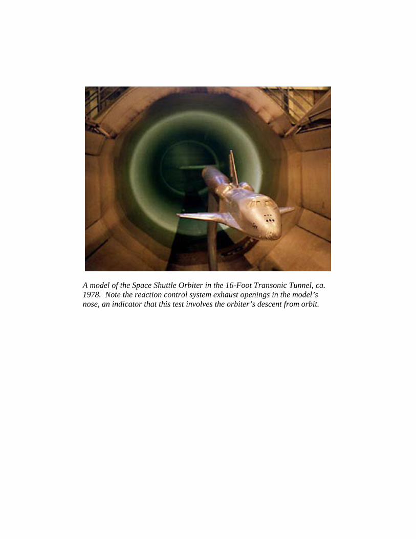
A model of the Space Shuttle Orbiter in the 16-Foot Transonic Tunnel, ca. 1978. Note the reaction control system exhaust openings in the model’s nose, an indicator that this test involves the orbiter’s descent from orbit.
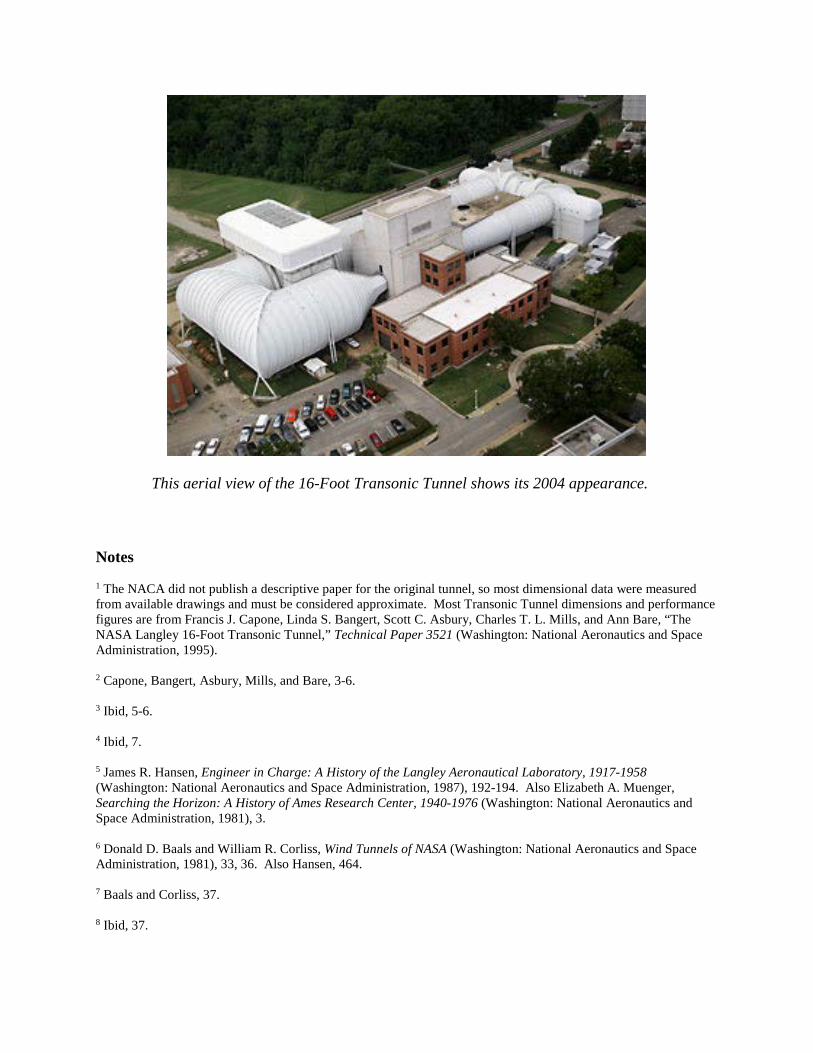
This aerial view of the 16-Foot Transonic Tunnel shows its 2004 appearance. Notes 1 The NACA did not publish a descriptive paper for the original tunnel, so most dimensional data were measured from available drawings and must be considered approximate. Most Transonic Tunnel dimensions and performance figures are from Francis J. Capone, Linda S. Bangert, Scott C. Asbury, Charles T. L. Mills, and Ann Bare, “The NASA Langley 16-Foot Transonic Tunnel,” Technical Paper 3521 (Washington: National Aeronautics and Space Administration, 1995). 2 Capone, Bangert, Asbury, Mills, and Bare, 3-6. 3 Ibid, 5-6. 4 Ibid, 7. 5 James R. Hansen, Engineer in Charge: A History of the Langley Aeronautical Laboratory, 1917-1958 (Washington: National Aeronautics and Space Administration, 1987), 192-194. Also Elizabeth A. Muenger, Searching the Horizon: A History of Ames Research Center, 1940-1976 (Washington: National Aeronautics and Space Administration, 1981), 3. 6 Donald D. Baals and William R. Corliss, Wind Tunnels of NASA (Washington: National Aeronautics and Space Administration, 1981), 33, 36. Also Hansen, 464. 7 Baals and Corliss, 37. 8 Ibid, 37.
9 The descriptive data for facilities shown here are from H. J. E. Reid to [Ralph E.] Ulmer, re. List of supersonic facilities, Oct. 27, 1947, National Archives and Records Administration, Mid-Atlantic Region Facility, Philadelphia, PA, Record Group 255, Box 422. 10 John V. Becker, The High-Speed Frontier: Case Histories of Four NACA Programs, 1920-1950 (Washington: National Aeronautics and Space Administration, 1980), 100-102. 11 Hansen, 464-466. Also Capone, Bangert, Asbury, Mills, and Bare, 1, 4-5, 19-22. 12 Capone, Bangert, Asbury, Mills, and Bare, 7-8. 13 Ibid, 2. 14 Ibid, 10-11. 15 Bill Uher, “NASA’s 16-Foot Transonic Tunnel Leaves Powerful Legacy” (Washington: National Aeronautics and Space Administration, Sept. 24, 2004), http://www.nasa.gov/vision/earth/improvingflight/16ft.html, 1-2.