15RE552 - TDAP-611 Installation Instructions -...
26
TDAP-611 AUDIO PANEL Installation Instructions TiL Document No. 15RE552 Rev. N/C MAY 2016 Technisonic Industries Limited 240 Traders Boulevard, Mississauga, Ontario L4Z 1W7 Tel: (905) 890-2113 Fax: (905) 890-5338 www.til.ca Copyright by Technisonic Industries Limited. All rights reserved.
Transcript of 15RE552 - TDAP-611 Installation Instructions -...

TDAP-611
AUDIO PANEL
Installation Instructions
TiL Document No. 15RE552 Rev. N/C
MAY 2016
Technisonic Industries Limited 240 Traders Boulevard, Mississauga, Ontario L4Z 1W7
Tel: (905) 890-2113 Fax: (905) 890-5338 www.til.ca
Copyright by Technisonic Industries Limited. All rights reserved.

TECHNISONIC INDUSTRIES LIMITED
TDAP-611 Installation Instructions TiL 15RE552 Rev. N/C ii
This page is intentionally left blank.

TECHNISONIC INDUSTRIES LIMITED
TDAP-611 Installation Instructions TiL 15RE552 Rev. N/C iii
REVISION HISTORY [ 15RE552 ]
REV SECTION - PAGE -
DESCRIPTION DATE EDITED BY
N/C Original document release. May 04, 2016 A.L.

TECHNISONIC INDUSTRIES LIMITED
TDAP-611 Installation Instructions TiL 15RE552 Rev. N/C iv
This page is intentionally left blank.
TECHNISONIC INDUSTRIES LIMITED
TDAP-611 Installation Instructions TiL 15RE552 Rev. N/C v
ESD CAUTION
This unit contains static sensitive devices. Wear a grounded wrist strap and/or conductive gloves when handling printed circuit boards.
WARNING AND DISCLAIMER
Changes or modifications not expressly approved by Technisonic Industries could void the user’s authority to operate the equipment. This manual is designed to provide information about the TDAP-611. Every effort has been made to make this manual as complete and accurate as possible. WARRANTY INFORMATION
The Model TDAP-611 Audio Panel is under warranty for one year from date of purchase. Failed units caused by defective parts or workmanship should be returned to: Technisonic Industries Limited 240 Traders Boulevard Mississauga, Ontario L4Z 1W7 Tel: (905) 890-2113 Fax: (905) 890-5338
NOTES

TECHNISONIC INDUSTRIES LIMITED
TDAP-611 Installation Instructions TiL 15RE552 Rev. N/C vi
SUMMARY OF DO-160G ENVIRONMENTAL TESTING
Summary of DO-160G Environmental Testing for the Technisonic Model TDAP-611 Audio Panel:
Conditions Paragraph Category
Temperature and Altitude 4.0 A2, B2, D1
Temperature Variation 5.0 B
Humidity 6.0 A
Operational Shocks and Crash Safety 7.0 B
Vibration: Sinusoidal Profile M
Random Profile B
Sine-on-random Profile G
8.0 S, U
Magnetic Effect 15.0 Z
Power Input 16.0 B
Voltage Spike 17.0 B
Audio Frequency Susceptibility 18.0 B
Induced Signal Susceptibility 19.0 ACE
Radio Frequency Susceptibility 20.0 T
Emission of Radio Frequency Energy 21.0 M
Lightning Induced Transient Susceptibility 22.0 A3E3XX
Electrostatic Discharge 25.0 A
Fire, Flammability 26.0 C

TECHNISONIC INDUSTRIES LIMITED
TDAP-611 Installation Instructions TiL 15RE552 Rev. N/C vii
SECTION TITLE PAGE
1 GENERAL DESCRIPTION B
1.1 INTRODUCTION ............................................................................................................ 1 1.2 DESCRIPTION ............................................................................................................... 1 1.3 TECHNICAL CHARACTERISTICS ................................................................................ 2 1.4 SYSTEM LIMITATIONS ................................................................................................. 3 1.4.1 POWER LIMITATIONS ................................................................................................ 3 1.4.2 FREQUENCY RESPONSE LIMITATIONS ................................................................... 3 1.4.3 CROSSTALK LIMITATIONS ........................................................................................ 3 1.4.4 TRANSMISSION PRIORITY ........................................................................................ 3 1.4.5 INDUCED SIGNAL SUSCEPTIBILITY, RF SUSCEPTIBILITY, AND RF EMISSION ........ 3
2 INSTALLATION INSTRUCTIONS B
2.1 GENERAL ...................................................................................................................... 5 2.2 EQUIPMENT PACKING LOG ........................................................................................ 5 2.3 INSTALLATION .............................................................................................................. 5 2.4 INSTALLATION KIT – CONTENTS ............................................................................... 5 2.5 WIRING REQUIREMENTS ............................................................................................ 5 2.6 TDAP-611 AUDIO PANEL INSTALLATION ................................................................... 6 2.6.1 CABLE CLEARANCE ................................................................................................... 6 2.6.2 SHIELD GROUNDS ..................................................................................................... 6
2.7 HEADPHONE INSTALLATION ...................................................................................... 11 2.8 MICROPHONE INSTALLATION .................................................................................... 11 2.9 PTT CONNECTIONS ..................................................................................................... 11 2.10 MAIN POWER +28 VDC .................................................................................................. 11 2.11 BACKLIGHTING POWER +28 VDC OR +5 VDC .............................................................. 11 2.12 STORAGE ...................................................................................................................... 11 2.13 POST-INSTALLATION ADJUSTMENTS ....................................................................... 15
APPENDIX A Support Notes .......................................................................................... 17 WARRANTY ................................................................................................................... 18
TABLE OF CONTENTS

TECHNISONIC INDUSTRIES LIMITED
TDAP-611 Installation Instructions TiL 15RE552 Rev. N/C viii
FIGURE TITLE PAGE
1 Outline Drawing .............................................................................................................. 7 2 TDAP-611 Rear Connectors .......................................................................................... 8 3 Wiring Connections for Communication Transceivers ................................................... 12 4 Wiring Connections for Navigation Receivers, Power, and Configurations .................... 13 5 Wiring Connections for User Interfaces ......................................................................... 14 6 Top Cover Post-Installation Adjustment Locations.......................................................... 15 7 Bottom Cover Post-Installation Adjustment Locations ................................................... 16
TABLE TITLE PAGE
1 TDAP-611 General Specifications .................................................................................. 2 2 Bottom Connector - J101 (50 Pin D Connections) - Use FEMALE Connector .............. 8 3 Bottom Connector – J202 (15 Pin D Connections) - Use MALE Connector .................. 9 4 Top Connector – J201 (37 Pin D Connections) - Use FEMALE Connector ................... 9 5 Top Connector – J102 (15 Pin D Connections) - Use FEMALE Connector ................... 10
LIST OF FIGURES
LIST OF TABLES

TECHNISONIC INDUSTRIES LIMITED
TDAP-611 Installation Instructions TiL 15RE552 Rev. N/C 1
1.1 INTRODUCTION
This publication provides operating information for the TDAP-611 Audio Panel. 1.2 DESCRIPTION
The Technisonic Digital Audio Panel (TDAP) Audio Management System TDAP-611 is a panel mounted Digital Audio System that provides centralized control and management for all audio signals within the airframe for up to 7 distinct Users (Pilot, Co-pilot, and five passengers) with varying degrees of connectivity depending on their station. The TDAP-611 connects to all aircraft Transceivers (up to a maximum of 8 distinct Transceiver Inputs), Navigational Receivers (up to a maximum of 8 distinct Receiver Inputs), Externally Alerting Sirens, and User Headsets. The TDAP-611 also includes functionality allowing expansion to an external PA or Paging system. The TDAP-611 supports full Simulcast transmitting as well as Monitor Only functionality amongst all connected Transceivers. The TDAP-611 User Stations can deliver >250 mW of audio into 150 Ω headsets at less than 1% total distortion. Push-button transmit selector switches allow immediate selection of any of the eight supported aircraft communications transceivers and a PA amplifier, while additional pull on volume knob audio input selector controls allow selection of any or all of the supported transceiver’s receive audio lines. To reduce pilot workload and avoid operational problems, ACCESS/D™ systems have auto-RX switching when a transmitter is selected. The TDAP-611 has a front panel selectable and adjustable VOX, LIVE, or KEYED intercom (ICS) functions. An EMERGENCY mode locking toggle provides "straight through" or “fail-passive” transmit and receive audio for the pilot or other user on a pre-set radio. In the NORMAL position (front panel LED is green), the pilot's audio is provided as selected by all of the panel controls and is part of the ICS system. Separate RX and ICS volume controls are provided on the panel along with an ICS VOX threshold control.
SECTION 1: GENERAL DESCRIPTION
TECHNISONIC INDUSTRIES LIMITED
TDAP-611 Installation Instructions TiL 15RE552 Rev. N/C 2
1.3 TECHNICAL CHARACTERISTICS
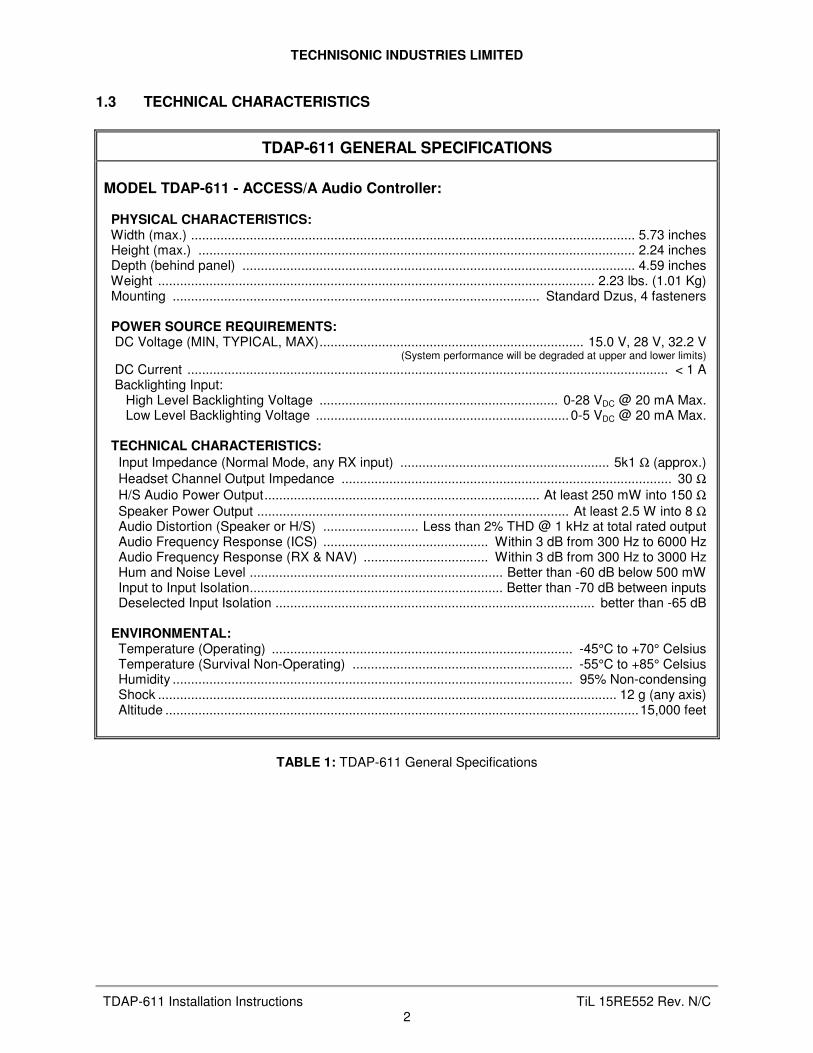
TDAP-611 GENERAL SPECIFICATIONS
MODEL TDAP-611 - ACCESS/A Audio Controller: PHYSICAL CHARACTERISTICS: Width (max.) ......................................................................................................................... 5.73 inches Height (max.) ....................................................................................................................... 2.24 inches Depth (behind panel) ........................................................................................................... 4.59 inches Weight ....................................................................................................................... 2.23 lbs. (1.01 Kg) Mounting .................................................................................................... Standard Dzus, 4 fasteners POWER SOURCE REQUIREMENTS: DC Voltage (MIN, TYPICAL, MAX)........................................................................ 15.0 V, 28 V, 32.2 V (System performance will be degraded at upper and lower limits)
DC Current ................................................................................................................................... < 1 A Backlighting Input: High Level Backlighting Voltage ................................................................. 0-28 VDC @ 20 mA Max. Low Level Backlighting Voltage ..................................................................... 0-5 VDC @ 20 mA Max. TECHNICAL CHARACTERISTICS:
Input Impedance (Normal Mode, any RX input) ......................................................... 5k1 Ω (approx.) Headset Channel Output Impedance .......................................................................................... 30 Ω H/S Audio Power Output........................................................................... At least 250 mW into 150 Ω Speaker Power Output ..................................................................................... At least 2.5 W into 8 Ω Audio Distortion (Speaker or H/S) .......................... Less than 2% THD @ 1 kHz at total rated output Audio Frequency Response (ICS) ............................................. Within 3 dB from 300 Hz to 6000 Hz Audio Frequency Response (RX & NAV) .................................. Within 3 dB from 300 Hz to 3000 Hz Hum and Noise Level ..................................................................... Better than -60 dB below 500 mW Input to Input Isolation..................................................................... Better than -70 dB between inputs Deselected Input Isolation ....................................................................................... better than -65 dB ENVIRONMENTAL: Temperature (Operating) .................................................................................. -45°C to +70° Celsius Temperature (Survival Non-Operating) ............................................................ -55°C to +85° Celsius Humidity ............................................................................................................. 95% Non-condensing Shock ............................................................................................................................. 12 g (any axis) Altitude .................................................................................................................................15,000 feet
TABLE 1: TDAP-611 General Specifications

TECHNISONIC INDUSTRIES LIMITED
TDAP-611 Installation Instructions TiL 15RE552 Rev. N/C 3
1.4 SYSTEM LIMITATIONS
A summary of the relevant system limitations is given below.
1.4.1 POWER LIMITATIONS
With Standard Set-up, which consists of seven headsets connected, a power output of not less than 250 mW is delivered per headset (as represented by 150 ohms). Nominal microphone input: 250 mVrms; Nominal Communications/Navigational Input: 2.5 Vrms.
1.4.2 FREQUENCY RESPONSE LIMITATIONS
In accordance with the provisions made in RTCA/DO-214 Sections 2.8.1 and 1.5.1, the communications transmit out and receiver channels (communications and navigational) possess an effective bandwidth of 300 Hz – 3000 Hz with a maximum amplitude variation of 3 dB within the frequency range.
1.4.3 CROSSTALK LIMITATIONS
To ensure that the crosstalk specifications are in accordance with the applicable sections of DO-214, it is essential that
1) Manufacturer’s maximum microphone input voltage of -4.7 dBu must not be exceeded in order to avoid jeopardising input to microphone output crosstalk results, particularly at the low frequency end.
2) In the instance where only two access units are daisy chained via their ICS tie-lines, a resistor of not greater than 600 ohms must be maintained across the ICS tie-line in order to avoid jeopardising station to station crosstalk results in RX mode at the high frequency end.
When multiple transceivers are selected for simulcast operation, they are bound together at the station output; thus, they are also bound together for other stations as well and defeat crosstalk measurements. All measurements are based on single transceiver TX selection.
1.4.4 TRANSMISSION PRIORITY
Where Pilot and Co-pilot transmit simultaneously, the Pilot transmissions take precedence over those of the Co-pilot. Co-pilot transmissions in this case would be rendered inactive.
1.4.5 INDUCED SIGNAL SUSCEPTIBILITY, RF SUSCEPTIBILITY, AND RF EMISSION
The wiring connections called out in Chapter 2 describe shield terminations for minimum ground loop noise. The test harnesses used for RTCA/DO-160 Sections 19, 20, and 21 – Induced Signal Susceptibility, RF Susceptibility, and Emission of RF Energy respectively – used shield terminations at both ends of the cable. Should RF susceptibility pose a problem in a particular installation, the installer may wish to try terminating shields at both ends of the cable. If this does not produce satisfactory results, then double shielding may be required.

TECHNISONIC INDUSTRIES LIMITED
TDAP-611 Installation Instructions TiL 15RE552 Rev. N/C 4
This page is intentionally left blank.

TECHNISONIC INDUSTRIES LIMITED
TDAP-611 Installation Instructions TiL 15RE552 Rev. N/C 5
2.1 GENERAL
This section contains information and instructions for the correct installation of the TDAP-611 Audio Panel. Make certain that the unit is correctly operating in accordance with the equipment user's requirements and manufacturer’s specifications, prior to releasing the equipment for service.
2.2 EQUIPMENT PACKING LOG
Unpack the equipment and check for any damage that may have occurred during transit. Save the original shipping container for returns due to damage or warranty claims. Check that each item on the packing slip has been shipped in the container.
2.3 INSTALLATION
The TDAP-611 Audio Panel is designed to be Dzus mounted and should be installed in conjunction with an IN-TDAP611 installation kit. See Figure 1 for an outline drawing of the unit with dimensions to facilitate the installation.
2.4 INSTALLATION KIT – CONTENTS
The IN-TDAP611 installation kit (P/N 159639) consists of:
1. One 50 Pin Cannon D mating connector (female) complete with crimp pins and hood.
2. One 37 Pin Cannon D mating connector (female) complete with crimp pins and hood.
3. One 15 Pin HD Cannon D mating connector (female) complete with crimp pins and hood.
4. One 15 Pin HD Cannon D mating connector (male) complete with crimp pins and hood.
2.5 WIRING REQUIREMENTS
Airframe wiring should be either: 1) Single conductor in accordance with MIL-W-22759 or multi-conductor in accordance with MIL-C-27500 2) Raychem 44 (81044) or 55 single or multi-conductor and shielded wire. Heat shrink solder sleeves (such as Raychem or equivalent) should be utilized for shield termination. All microphone audio input and output line connections should be made with 2 conductor, twisted pair shielded cables as illustrated in Figures 3 to 5. Receiver audio input lines should also be 2 conductor, twisted pair shielded cables. The power and ground lines should be a minimum of #22 AWG (#20 preferred). Keying and all audio lines may be #24 AWG or larger.
NOTE: Do not bundle any low level audio lines with RF coaxial cables, 60 Hz or 400 Hz AC
inverter, or motor, pump, or blower wiring, which can cause noise coupling between the various systems, especially during RF transmission or pump/blower mechanical operation. Maintain as much distance as possible from these types of wire bundles.
Note that there is really no effective field-installable shielding for magnetic coupling (which occurs at high currents), and the only suitable prevention for this type of interference is distance between the interfering lines. Shielded wiring is effective only for electrostatic coupling or voltage driven interference.
SECTION 2: INSTALLATION INSTRUCTIONS
TECHNISONIC INDUSTRIES LIMITED
TDAP-611 Installation Instructions TiL 15RE552 Rev. N/C 6
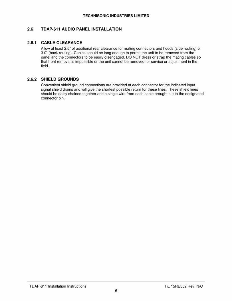
2.6 TDAP-611 AUDIO PANEL INSTALLATION 2.6.1 CABLE CLEARANCE
Allow at least 2.5” of additional rear clearance for mating connectors and hoods (side routing) or 3.0” (back routing). Cables should be long enough to permit the unit to be removed from the panel and the connectors to be easily disengaged. DO NOT dress or strap the mating cables so that front removal is impossible or the unit cannot be removed for service or adjustment in the field.
2.6.2 SHIELD GROUNDS
Convenient shield ground connections are provided at each connector for the indicated input signal shield drains and will give the shortest possible return for these lines. These shield lines should be daisy chained together and a single wire from each cable brought out to the designated connector pin.

TECHNISONIC INDUSTRIES LIMITED
TDAP-611 Installation Instructions TiL 15RE552 Rev. N/C 7
4.94
4.85
4.59
2.24
5.73
FIGURE 1: Outline Drawing for Model TDAP-611
”
”
””
”

TECHNISONIC INDUSTRIES LIMITED
TDAP-611 Installation Instructions TiL 15RE552 Rev. N/C 8
2.6 INSTALLATION – PIN LOCATIONS AND CONNECTIONS
FIGURE 2: TDAP-611 Rear Connectors
J101 – POWER, MICS & KEYS Connector Pin Assignments
LO HI KEY Connection Notes
34 17 +28 VDC Power In Main Power Input
40 23 6 Pilot’s Mic In
9 Pilot’s ICS Key Active when grounded
41 24 7 Co-Pilot’s Mic In
26 Co-Pilot’s ICS Key Active when grounded
42 25 8 Hand Mic In Emergency Hand Mic
35 18 PAX 1 Mic In
36 19 PAX 2 Mic In
37 20 PAX 3 Mic In
38 21 PAX 4 Mic In
39 22 PAX 5 Mic In
4 PAX ICS Key
1 3 Backlighting Power Input
2 Lighting 28 V / 5 V Select Open: 28 V Backlighting Ground: 5 V Backlighting
5 Speaker Volume Control 10K Pot: Speaker Volume Ground: Speaker Disabled
44 27 10 COM 7 TX Mic Out
45 28 11 COM 6 TX Mic Out
46 29 12 COM 5 TX Mic Out
47 30 13 COM 4 TX Mic Out
48 31 14 COM 3 TX Mic Out
49 32 15 COM 2 TX Mic Out
50 33 16 COM 1 TX Mic Out
43 Shield ground for mic lines
TABLE 2: Bottom Connector - J101 (50 Pin D Connections) - Use FEMALE Connector

TECHNISONIC INDUSTRIES LIMITED
TDAP-611 Installation Instructions TiL 15RE552 Rev. N/C 9
J202 – HEADSETS CONNECTOR PIN ASSIGNMENTS
LO HI Connection Notes
9 1 Pilot’s H/S Audio
10 2 Direct Alert Connection High level headset direct audio
(via resistive pad). Never connect together between multiple units.
11 3 Co-Pilot’s H/S Audio
4 PAX 1 H/S Audio
5 PAX 2 H/S Audio
12 PAX 3 H/S Audio
13 PAX 4 H/S Audio
6 PAX 5 H/S Audio
14 PAX H/S Common
15 7 Speaker Output 8 Ohms
8 Shield Ground
TABLE 3: Bottom Connector – J202 (15 Pin D Connections) - Use MALE Connector
The Pin 2/10 Direct Input is connected directly to the pilot’s H/S via a resistive pad and, if multiple units use this connection to a common source, significant crosstalk will result. Connect ONLY ONE station in this way to a single external source.
J201 – RX INPUTS, ICS TIES CONNECTOR PIN ASSIGNMENTS
LO HI Connection Notes
20 1 CREW ICS Tie ICS Tie Line Between Units
21 2 PAX ICS Tie ICS Tie Line Between Units
22 3 Direct Audio 1 Un-switched Direct Input
4 Shield Ground Shield drain for input lines.
23 5 NAV 8 RX Audio Mapped to NAV2 knob
24 6 NAV 7 RX Audio Mapped to NAV2 knob
25 7 Music Left Audio Mapped to MUSIC knob
26 8 Music Right Audio Mapped to MUSIC knob
27 9 NAV 4 RX Audio Mapped to NAV1 knob
28 10 NAV 3 RX Audio Mapped to NAV1 knob
29 11 NAV 2 RX Audio Mapped to NAV1 knob
30 12 NAV 1 RX Audio Mapped to NAV1 knob
31 13 COM 7 RX Audio
32 14 COM 6 RX Audio
33 15 COM 5 RX Audio
34 16 COM 4 RX Audio
35 17 COM 3 RX Audio
36 18 COM 2 RX Audio
37 19 COM 1 RX Audio
TABLE 4: Top Connector – J201 (37 Pin D Connections) - Use FEMALE Connector

TECHNISONIC INDUSTRIES LIMITED
TDAP-611 Installation Instructions TiL 15RE552 Rev. N/C 10
J102 – ALERTS, PA CONNECTOR PIN ASSIGNMENTS
LO HI Connection Notes
9 1 Direct Audio 2 Un-switched Direct Input
11 3 PA Mic Out To External PA System
2 PA Key Output (Active Low) To External PA system
10 PA Power Key Output (Active Low) To External PA system Can be used to activate a remote PA system.
12 4 COM 8 RX Audio
6 5 COM 8 TX Mic Out
7 COM 8 TX Key
8 PAX RX Enable Open: PAX receive no RX Audio Ground: PAX receive RX Audio
13 Alert 3 (in) Two-Tone, Timed (Rad Alt DH) Active when grounded. Accepts +28 VDC.
14 Alert 2 (in) Pulsing Tone (Low Rotor) Active when grounded. Accepts +28 VDC.
15 Alert 1 (in) Steady Tone (Engine Fail) Active when grounded. Accepts +28 VDC.
TABLE 5: Top Connector – J102 (15 Pin D Connections) - Use FEMALE Connector Alerting is tone based with Alert 1 emitting a steady tone, Alert 2 a pulsing tone, and Alert 3 a two-tone, timed signal. Alert 2 has priority over Alert 1 if both are activated at the same time. Alert 3 has priority over Alert 2 and Alert 1.

TECHNISONIC INDUSTRIES LIMITED
TDAP-611 Installation Instructions TiL 15RE552 Rev. N/C 11
2.7 HEADPHONE INSTALLATION
The TDAP-611 Audio Panel are intended for use with industry standard 150 ohm headphones. In all cases, the headset lines should be run as shielded, twisted pairs, to avoid contamination (and resulting crosstalk) of companion low level mic lines or audio input lines. Failure to follow this wiring guideline will result in unwanted crosstalk and phantom audio that will appear to be transmit or intercom related. The use of high quality headsets and “carbon-equivalent” boom microphones, such as David Clark or Bose, is strongly recommended. The use of headsets with individual volume controls is very useful for passengers and allows level adjustment suitable to each position due to differing headsets and the inevitable different hearing capability of individual users.
2.8 MICROPHONE INSTALLATION
All microphone connections to the TDAP-611 must be done with shielded cables. The inputs are intended for use with standard “carbon-equivalent” or amplified dynamic microphones (such as the D/C M1, M4 M7, etc.). Shielded, twisted pair routing is strongly preferred for lowest noise pick-up, but single conductor shielded wiring generally gives adequate results in non-critical or single box installations (although noise floor and crosstalk will increase).
2.9 PTT CONNECTIONS
The Pilot, Co-pilot, and hand microphones require a PTT (Push To Talk) button or switch to key the transceivers as required. If a hand-held microphone is used, tie the PTT button to the appropriate key line. If a boom microphone is incorporated into the headset, an external switch (such as the cyclic switch or yoke switch) will be required to key the transmitter. PTT lines should go directly to ground to activate the desired key function.
2.10 MAIN POWER +28 VDC
The main power +28 VDC is connected to Pin 17 of the 50 pin (lower) "D" connector. The main power ground is connected to Pin 34 of the 50 pin (lower) "D" connector. As previously indicated, this connection should be made with at least #22 AWG wire, with #20 preferred. If from a very noisy source, with high levels of parasitic AC, shielding may improve rejection of this coupled AC into other low level audio lines.
2.11 BACKLIGHTING POWER +28 VDC or +5 VDC
The backlighting power is connected to Pin 3 of the 50 pin (lower) "D" connector. The backlighting ground is connected to Pin 1 of the 50 pin (lower) "D" connector. The backlighting input voltage level can be switched between a 0-28 VDC range of a 0-5 VDC through Pin 2 of the 50 pin (lower) "D" connector (Ground = 5 VDC Backlighting). Backlighting is NVG/ANVIS compatible (green).
2.12 STORAGE
When not in use, store the TDAP-611 in the original anti-static bag if possible and in a non-humid place. Optimum storage temperatures for the best shelf life should not exceed +35°C or be less than -10°C.

TECHNISONIC INDUSTRIES LIMITED
TDAP-611 Installation Instructions TiL 15RE552 Rev. N/C 12
COM1
COM215
49COM2 MIC AUDIO LO
COM2 MIC AUDIO HI
COM2 MIC KEY
COM3
COM4
COM5
COM6
COM4 MIC KEY
COM4 MIC AUDIO HI
COM3 MIC AUDIO HI
COM3 MIC KEY
13
47
30
14
31
48
COM6 MIC KEY
COM6 MIC AUDIO HI
COM5 MIC AUDIO HI
COM5 MIC KEY
11
45
28
12
29
46
27
44
10
COM7 MIC AUDIO HI
COM7 MIC KEY
COM4 MIC AUDIO LO
COM3 MIC AUDIO LO
COM6 MIC AUDIO LO
COM5 MIC AUDIO LO
COM7 MIC AUDIO LO
COM7
18
36COM2 AUDIO IN LO
COM2 AUDIO IN HI
COM3 AUDIO IN HI
COM3 AUDIO IN LO 35
17
34
14
13
31
32
15
33
16
COM5 AUDIO IN HI
COM5 AUDIO IN LO
COM6 AUDIO IN LO
COM6 AUDIO IN HI
COM7 AUDIO IN LO
COM7 AUDIO IN HI
COM4 AUDIO IN LO
COM4 AUDIO IN HI
COM8 AUDIO IN LO
COM8 AUDIO IN HI 4
12
COM8
19
37COM1 AUDIO IN LO
COM1 AUDIO IN HI
32
16
33
50
COM1 MIC KEY
COM1 MIC AUDIO HI
COM1 MIC AUDIO LO
P201
P101
P102
7
5
6
COM8 MIC AUDIO HI
COM8 MIC KEY
COM8 MIC AUDIO LO
RX
MIC
PTT
PTT
MIC
RX
PTT
MIC
RX
PTT
MIC
RX
PTT
MIC
RX
PTT
MIC
RX
PTT
MIC
RX
PTT
MIC
RX
43CHASSIS GROUNDP101
P201
P201
P201
P201
P201
P201
P101
P101
P101
P101
P101
P101
TDAP-611
FIGURE 3: Wiring Connections for Communication Transceivers

TECHNISONIC INDUSTRIES LIMITED
TDAP-611 Installation Instructions TiL 15RE552 Rev. N/C 13
NAV1 AUDIO IN LO
NAV1 AUDIO IN HI 12
30
29
11NAV2 AUDIO IN HI
NAV2 AUDIO IN LO
26
28
10
8
MUSIC R AUDIO IN LO
MUSIC R AUDIO IN HI
NAV3 AUDIO IN LO
NAV3 AUDIO IN HI
23
24
5
25
7
6
NAV8 AUDIO IN HI
NAV8 AUDIO IN LO
NAV7 AUDIO IN LO
NAV7 AUDIO IN HI
MUSIC L AUDIO IN LO
MUSIC L AUDIO IN HI
27
9
NAV4 AUDIO IN LO
NAV4 AUDIO IN HI
PAX ICS TIE AUDIO IN HI
CREW ICS TIE AUDIO IN LO
CREW ICS TIE AUDIO IN HI
PAX ICS TIE AUDIO IN LO
DIR1 AUDIO IN HI
DIR1 AUDIO IN LO
2
20
21
1
22
3
NAV2
NAV1
MUSIC
NAV4
NAV3
NAV7
PLAYER
NAV8
DIR1
EXPANSIONTDAP-611
1
9DIR2 AUDIO IN LO
DIR2 AUDIO IN HI
P201
P102
P201
DIR2
DIR ALERT10
2
DIRECT ALERT LO
DIRECT ALERT HI
P1023PA MIC HI
11PA MIC LO
2PA KEY
10PA POWER KEY
PACONTROLLER
15ALERT1 KEY
14ALERT2 KEY
13ALERT3 KEY
8PAX RX ENABLE
2LIGHTING 28V/5VP101
5SPEAKER VOLUME
1728 VDC AIRCRAFT BUSS
34POWER GROUND
LIGHTING BUSS3
1LIGHTING GROUND
LIGHTING
43CHASSIS GROUND
TDAP-611
P202
FIGURE 4: Wiring Connections for Navigation Receivers, Power, and Configurations

TECHNISONIC INDUSTRIES LIMITED
TDAP-611 Installation Instructions TiL 15RE552 Rev. N/C 14
PILOT
1
9PILOT HEADSET AUDIO LO
PILOT HEADSET AUDIO HI
23
40
PILOT MIC IN HI
PILOT MIC IN LO
P202
P101
PH
MIC
HEADSET
MIC
PH
HEADSETCOPILOT
24
41
3
11
35
18P101
14
4
PAX1
MIC
HEADSET
PH
36
19
5
MIC
HEADSET
PH
37
20
12
MIC
HEADSET
PH
38
21
13
MIC
HEADSET
PH
39
22P101
6
MIC
HEADSET
PH
COPILOT HEADSET AUDIO LO
COPILOT HEADSET AUDIO HI
COPILOT MIC IN LO
COPILOT MIC IN HI
PAX1 HEADSET AUDIO LO
PAX1 HEADSET AUDIO HI
PAX1 MIC IN LO
PAX1 MIC IN HI
PAX2 MIC IN LO
PAX2 MIC IN HI
PAX2 HEADSET AUDIO HI
PAX3 MIC IN LO
PAX3 MIC IN HI
PAX3 HEADSET AUDIO HI
PAX4 MIC IN LO
PAX4 MIC IN HI
PAX4 HEADSET AUDIO HI
PAX5 MIC IN LO
PAX5 MIC IN HI
PAX5 HEADSET AUDIO HI
PAX2
PAX3
PAX4
PAX5
PILOT ICS KEY 9
6PILOT TX KEY
26
7COPILOT TX KEY
COPILOT ICS KEY
4PAX ICS KEY
25
8
42
HAND MIC KEY
HAND MIC IN HI
HAND MIC IN LO
HAND MICKEY
PH
8P202
CHASSIS GROUND
TDAP-611
7
15
P202
SPEAKERSPEAKER B
SPEAKER A
P202
P202
P202
P202
P202
P202
P101
P101
P101
P101
FIGURE 5: Wiring Connections for User Interfaces
TECHNISONIC INDUSTRIES LIMITED
TDAP-611 Installation Instructions TiL 15RE552 Rev. N/C 15
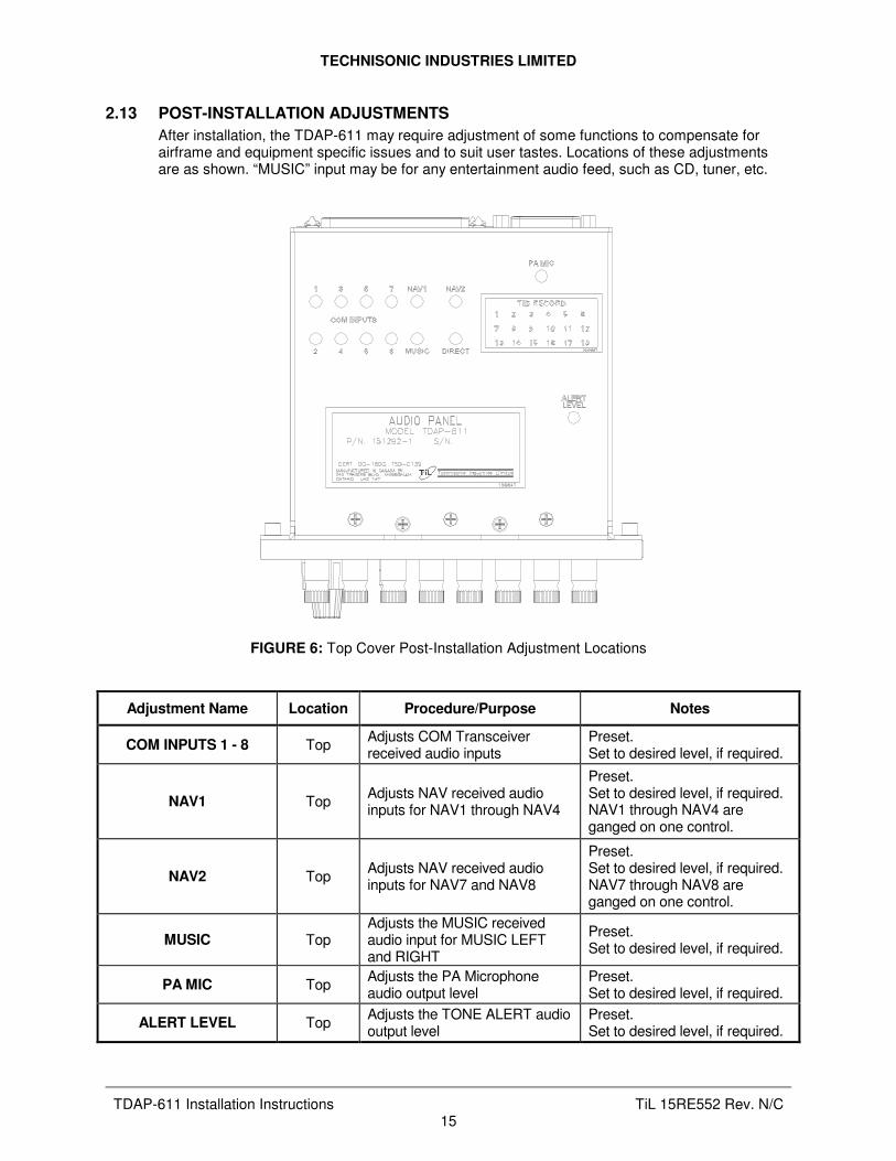
2.13 POST-INSTALLATION ADJUSTMENTS
After installation, the TDAP-611 may require adjustment of some functions to compensate for airframe and equipment specific issues and to suit user tastes. Locations of these adjustments are as shown. “MUSIC” input may be for any entertainment audio feed, such as CD, tuner, etc.
FIGURE 6: Top Cover Post-Installation Adjustment Locations
Adjustment Name Location Procedure/Purpose Notes
COM INPUTS 1 - 8 Top Adjusts COM Transceiver received audio inputs
Preset. Set to desired level, if required.
NAV1 Top Adjusts NAV received audio inputs for NAV1 through NAV4
Preset. Set to desired level, if required. NAV1 through NAV4 are ganged on one control.
NAV2 Top Adjusts NAV received audio inputs for NAV7 and NAV8
Preset. Set to desired level, if required. NAV7 through NAV8 are ganged on one control.
MUSIC Top Adjusts the MUSIC received audio input for MUSIC LEFT and RIGHT
Preset. Set to desired level, if required.
PA MIC Top Adjusts the PA Microphone audio output level
Preset. Set to desired level, if required.
ALERT LEVEL Top Adjusts the TONE ALERT audio output level
Preset. Set to desired level, if required.

TECHNISONIC INDUSTRIES LIMITED
TDAP-611 Installation Instructions TiL 15RE552 Rev. N/C 16
FIGURE 7: Bottom Cover Post-Installation Adjustment Locations
Adjustment Name Location Procedure/Purpose Notes
TX MIC OUTPUTS 1 - 8 Top Adjusts COM Transceiver Microphone audio output level
Preset. Set to desired level, if required.

TECHNISONIC INDUSTRIES LIMITED
TDAP-611 Installation Instructions TiL 15RE552 Rev. N/C 17
SUPPORT NOTES
• For the latest Service Bulletin(s), refer to the Publication Index list under the section for this model (login required).
• For the latest Technical Information Bulletins, please refer to the Publication Index list under the section for this model (login required).
• For the latest Software Release(s), please refer to the Publication Index list under the section for this model’s software/firmware history index (login required).
NOTES
APPENDIX A

TECHNISONIC INDUSTRIES LIMITED
TDAP-611 Installation Instructions TiL 15RE552 Rev. N/C 18
Technisonic Industries Limited 240 Traders Blvd., Mississauga, ON Canada L4Z 1W7
Tel: (905) 890-2113 Fax: (905) 890-5338
IMPORTANT
WARRANTY All communication equipment manufactured by Technisonic Industries Limited is warranted to be free of defects in Material or Workmanship under normal use for a period of one year from Date of Purchase by the end user. Warranty will only apply to equipment installed by a factory approved and/or authorized facility in accordance with Technisonic published installation instructions. Equipment falling under the following is not covered by warranty: • Equipment that has been repaired or altered in any way as to affect performance • Equipment that has been subject to improper installation • Equipment that has been used for purposes other than intended • Equipment that has been involved in any accident, fire, flood, immersion, or subject to
any other abuse. Expressly excluded from this warranty are changes or charges relating to the removal and re-installation of equipment from the aircraft. Technisonic will repair or replace (at Technisonic's discretion) any defective transceiver (or part thereof) found to be faulty during the Warranty Period. Faulty equipment must be returned to Technisonic (or its authorized Warranty Depot) with transportation charges prepaid. Repaired (or replacement) equipment will be returned to the customer with collect freight charges. If the failure of a transceiver occurs within the first 30 days of service, Technisonic will return the repaired or replacement equipment prepaid. Technisonic reserves the right to make changes in design, or additions to, or improvements in its products without obligation to install such additions and improvements in equipment previously manufactured. This Warranty is in lieu of any and all other warranties express or implied, including any warranty of merchantability or fitness, and of all other obligations or liabilities on the part of Technisonic. This Warranty shall not be transferable or assignable to any other persons, firms, or corporations.
For warranty registration, please complete the online Warranty Registration Form found at www.til.ca.