15105BearGuideFIN-2012-04-27sfa - QUARK 8 …€¦ · Construction Guide The Pre-Finished,...
78
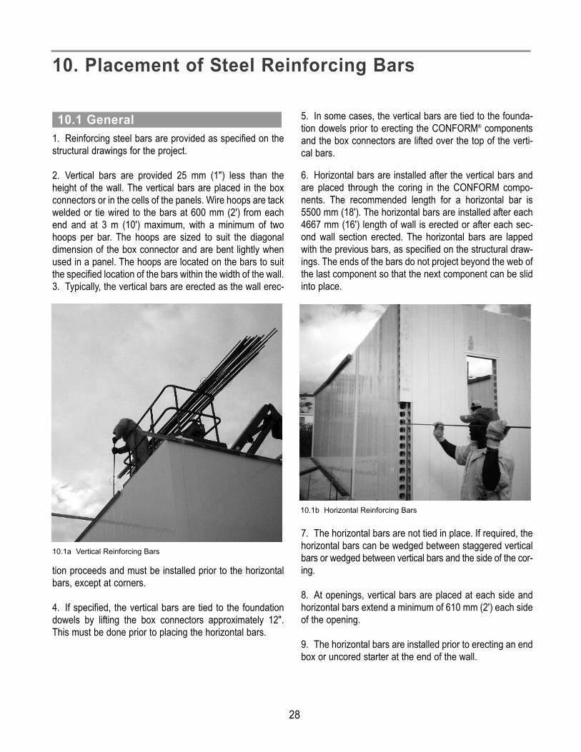
Construction Guide The Pre-Finished, Stay-in-Place Concrete Wall Formwork Version 2.0
Transcript of 15105BearGuideFIN-2012-04-27sfa - QUARK 8 …€¦ · Construction Guide The Pre-Finished,...

Construct ion Guide
The Pre-F in ished, Stay- in-PlaceConcrete Wal l Formwork
Vers ion 2.0

Nuform Building Technologies Inc. is an inno-vative quality-driven building technologies compa-ny. Since the introduction of CONFORM® (formerlyRoyal Building SystemsTM) in 1992, the producthas received global recognition for its approachin providing an innovative solution to the con-struction industry.CONFORM is a patented polymer-based stay-in-place formwork for concrete walls. The extrudedcomponents slide and interconnect together to cre-ate a concrete formwork. The result is perma-nent, attractive, and pre-finished concrete wallsthat can be easily constructed in any climate. CONFORM is composed of numerous modularcomponents for 100mm, 150mm and 200mm (4”, 6” and 8”) concrete walls that can be assem-bled to suit any wall layout, whether you are build-ing a vehicle wash, an agricultural facility or alarge industrial building.
CONFORM requires no painting, and resists ultra-violet radiation. The polymer components will notdecay or deteriorate over a lifespan that can bemeasured in decades. Furthermore, CONFORMis highly durable, virtually maintenance free,impervious to weather, and energy efficient.CONFORM is manufactured using ‘R3’ extrusiontechnology as an environmentally friendly prod-uct. The polymer components contain over 55%recycled content and are recyclable, energy effi-cient, mold and mildew resistant and non-toxic.CONFORM offers complete design flexibility andan innovative building product that is easy tomaintain, friendly to the environment, and builtto last. Whether you are a developer, contractor,architect, engineer, or designer you can find attrac-tive and cost effective solutions for your next proj-ect with CONFORM.
© Copyright 2012 Nuform Building Technologies Inc.All rights reserved. No part of this publication may be reproduced in any form or by any means without written permission from Nuform Building Technologies Inc.All other products, names and services are trademarks or registered trademarks of their respective companies.
Bui ld ing Solut ions for a Bet ter Wor ld…

Contents1. Introduction . . . . . . . . . . . . . . . . . . . . . . . . . . 12. Project Organization . . . . . . . . . . . . . . . . . . . 2
2.1 General . . . . . . . . . . . . . . . . . . . . . . . . . . . . . . . . . . . 22.2 Planning . . . . . . . . . . . . . . . . . . . . . . . . . . . . . . . . . . 22.3 Individual Components . . . . . . . . . . . . . . . . . . . . . . . 32.4 Pre-assembled Wall Sections . . . . . . . . . . . . . . . . . . 4
3. Wall Materials . . . . . . . . . . . . . . . . . . . . . . . . . 53.1 CONFORM® Components . . . . . . . . . . . . . . . . . . . . . 53.2 Concrete Mix . . . . . . . . . . . . . . . . . . . . . . . . . . . . . . . 73.3 Steel Reinforcing Bars . . . . . . . . . . . . . . . . . . . . . . . 83.4 Fasteners, Bracing, Others . . . . . . . . . . . . . . . . . . . . 9
4. Equipment . . . . . . . . . . . . . . . . . . . . . . . . . . . 104.1 Hand Tools . . . . . . . . . . . . . . . . . . . . . . . . . . . . . . . 104.2 Power Tools . . . . . . . . . . . . . . . . . . . . . . . . . . . . . . . 104.3 Erection Equipment . . . . . . . . . . . . . . . . . . . . . . . . . 104.4 Construction Equipment . . . . . . . . . . . . . . . . . . . . . 10
5. Safety . . . . . . . . . . . . . . . . . . . . . . . . . . . . . . . 115.1 Workmen . . . . . . . . . . . . . . . . . . . . . . . . . . . . . . . . . 115.2 Weather Conditions . . . . . . . . . . . . . . . . . . . . . . . . . 11
6. Site Preparations . . . . . . . . . . . . . . . . . . . . . 126.1 Site Grading and Access . . . . . . . . . . . . . . . . . . . . 126.2 Storage of Material . . . . . . . . . . . . . . . . . . . . . . . . . 126.3 Foundations . . . . . . . . . . . . . . . . . . . . . . . . . . . . . . 136.4 Wall Dowels . . . . . . . . . . . . . . . . . . . . . . . . . . . . . . 136.5 Underground Services . . . . . . . . . . . . . . . . . . . . . . 146.6 Electrical Power . . . . . . . . . . . . . . . . . . . . . . . . . . . 146.7 Water Supply . . . . . . . . . . . . . . . . . . . . . . . . . . . . . . 14
7. Wall Erection - General . . . . . . . . . . . . . . . . 157.1 Orientation . . . . . . . . . . . . . . . . . . . . . . . . . . . . . . . . 157.2 Layout . . . . . . . . . . . . . . . . . . . . . . . . . . . . . . . . . . . 157.3 Erection Procedure . . . . . . . . . . . . . . . . . . . . . . . . . 167.4 Wall Length . . . . . . . . . . . . . . . . . . . . . . . . . . . . . . . 177.5 Starters . . . . . . . . . . . . . . . . . . . . . . . . . . . . . . . . . . 177.6 Doors, Windows, Openings . . . . . . . . . . . . . . . . . . 187.7 Electrical . . . . . . . . . . . . . . . . . . . . . . . . . . . . . . . . . 20
8. Wall Erection- Individual Components . . . . . . . . . . . . . . . 218.1 Erection Procedure . . . . . . . . . . . . . . . . . . . . . . . . . 218.2 Erection Sequence . . . . . . . . . . . . . . . . . . . . . . . . . 21
9. Wall Erection- Pre-assembled Wall Sections . . . . . . . . . . 239.1 Erection Procedure . . . . . . . . . . . . . . . . . . . . . . . . . 239.2 Individual Components . . . . . . . . . . . . . . . . . . . . . . 249.3 Erection Sequence . . . . . . . . . . . . . . . . . . . . . . . . . 259.4 Doors, Windows, Openings . . . . . . . . . . . . . . . . . . 27
10. Placement of Steel Reinforcing Bars . . . . . 2810.1 General . . . . . . . . . . . . . . . . . . . . . . . . . . . . . . . . . . 2810.2 Corner Reinforcing Bars . . . . . . . . . . . . . . . . . . . . . 2910.3 Placement Sequence . . . . . . . . . . . . . . . . . . . . . . . 30
11. Bracing . . . . . . . . . . . . . . . . . . . . . . . . . . . . . 3211.1 General . . . . . . . . . . . . . . . . . . . . . . . . . . . . . . . . . . 3211.2 Base of Wall . . . . . . . . . . . . . . . . . . . . . . . . . . . . . . 3211.3 Mid-Height of Wall . . . . . . . . . . . . . . . . . . . . . . . . . . 3311.4 Top of Wall . . . . . . . . . . . . . . . . . . . . . . . . . . . . . . . 3411.5 Ends, Corners, Intersections . . . . . . . . . . . . . . . . . . 3411.6 Wall Openings . . . . . . . . . . . . . . . . . . . . . . . . . . . . . 36
12. Concrete Placement . . . . . . . . . . . . . . . . . . . 3812.1 Concrete Pour . . . . . . . . . . . . . . . . . . . . . . . . . . . . . 3812.2 Inserts . . . . . . . . . . . . . . . . . . . . . . . . . . . . . . . . . . . 4012.3 Washing . . . . . . . . . . . . . . . . . . . . . . . . . . . . . . . . . 4012.4 Remedial Measures . . . . . . . . . . . . . . . . . . . . . . . . 4012.5 Bracing . . . . . . . . . . . . . . . . . . . . . . . . . . . . . . . . . . 40
13. Finishing . . . . . . . . . . . . . . . . . . . . . . . . . . . . 4113.1 Clean-Up . . . . . . . . . . . . . . . . . . . . . . . . . . . . . . . . . 4113.2 Multi-storey Band . . . . . . . . . . . . . . . . . . . . . . . . . . 4113.3 Caulking . . . . . . . . . . . . . . . . . . . . . . . . . . . . . . . . . 4113.4 Maintenance . . . . . . . . . . . . . . . . . . . . . . . . . . . . . . 42
14. CONFORM® Repair . . . . . . . . . . . . . . . . . . . . 4414.1 Patching . . . . . . . . . . . . . . . . . . . . . . . . . . . . . . . . . 4414.2 Materials and Tools Required . . . . . . . . . . . . . . . . . 4414.3 Repairing Surface Damage - Patching Holes . . . . 4514.4 Repairing Surface Damage
- Patching Cracks or Butt Joints . . . . . . . . . . . . . . . 4615. Alternate Wall Finishes . . . . . . . . . . . . . . . . 47
15.1 CONFORM® . . . . . . . . . . . . . . . . . . . . . . . . . . . . . . 4715.2 Acrylic Stucco . . . . . . . . . . . . . . . . . . . . . . . . . . . . . 4715.3 Stucco - Direct Apply Method . . . . . . . . . . . . . . . . . 4715.4 Stucco - EIFS System Method . . . . . . . . . . . . . . . . 4815.5 Vinyl Graphics . . . . . . . . . . . . . . . . . . . . . . . . . . . . . 4815.6 Paint . . . . . . . . . . . . . . . . . . . . . . . . . . . . . . . . . . . . 4915.7 Insulation and Siding . . . . . . . . . . . . . . . . . . . . . . . . 5015.8 Gypsum Board . . . . . . . . . . . . . . . . . . . . . . . . . . . . 53
Appendix A - Construction Bulletins . . . . . . . . . . . . . . . 53
Appendix B - Bracing for CONFORM® . . . . . . . . . . . . . . . 54
B.1 General . . . . . . . . . . . . . . . . . . . . . . . . . . . . . . 54B.2 Bracing Design Guidelines . . . . . . . . . . . . . . . 55B.3 Single Bracing . . . . . . . . . . . . . . . . . . . . . . . . . 56B.4 Double Bracing . . . . . . . . . . . . . . . . . . . . . . . . 59B.5 Vertical Bracing at Corners,
I-Intersections and Ends . . . . . . . . . . . . . . . . . 60B.6 Bracing at Openings . . . . . . . . . . . . . . . . . . . . 65B.7 Bracing at Piers, Columns and Double Walls . 67B.8 Bracing Example . . . . . . . . . . . . . . . . . . . . . . . 68


This Construction Guide has been prepared by NuformBuilding Technologies Inc. (NUFORM®) to assist contractors,engineers and architects in the understanding of the con-struction procedures for bearing walls using CONFORM®. Itis a part of our continuing effort to provide current and prac-tical information to the users of CONFORM.The Construction Guide provides information on the fol-lowing aspects of construction using CONFORM:• Project Organization• Wall Materials• Equipment• Safety• Site Preparation• Wall Erection - General• Wall Erection - Individual components• Wall Erection - Pre-assembled Wall Sections• Placement of Steel Reinforcing Bars• Bracing• Concrete Placement• Finishing• Repair• Alternate Finishes
In addition to this Construction Guide, the following guidesare also available to assist in designing and building yourprojects using CONFORM:• Technical Guide• Engineering Guide
Although every effort has been made to ensure that all theinformation provided in the Construction Guide is factualand consistent with good construction practice, NUFORMdoes not assume any liability for errors or oversights result-ing from the use of information contained in this guide.Anyone making use of the information provided in theseguides assumes all liability arising from such use. The suggested suppliers for various products described inthis guide are for information purposes, only. NUFORMdoes not warrant or guarantee the performance the per-formance of any of the products. Please consult each sup-plier for specific information regarding their products, andrecommended application and warranty, if any.
1. Introduction
1.0 Bearing Wall Project
1
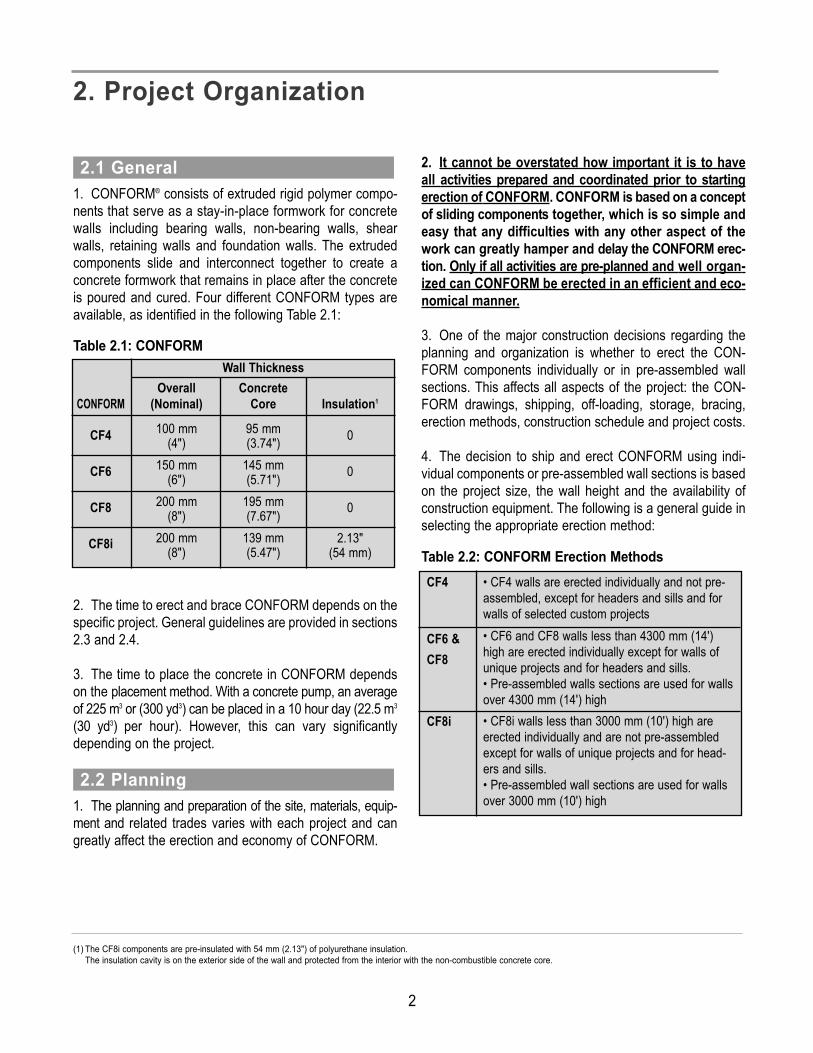
1. CONFORM® consists of extruded rigid polymer compo-nents that serve as a stay-in-place formwork for concretewalls including bearing walls, non-bearing walls, shearwalls, retaining walls and foundation walls. The extrudedcomponents slide and interconnect together to create aconcrete formwork that remains in place after the concreteis poured and cured. Four different CONFORM types areavailable, as identified in the following Table 2.1: Table 2.1: CONFORM
2. The time to erect and brace CONFORM depends on thespecific project. General guidelines are provided in sections2.3 and 2.4. 3. The time to place the concrete in CONFORM dependson the placement method. With a concrete pump, an averageof 225 m3 or (300 yd3) can be placed in a 10 hour day (22.5 m3
(30 yd3) per hour). However, this can vary significantlydepending on the project.
1. The planning and preparation of the site, materials, equip-ment and related trades varies with each project and cangreatly affect the erection and economy of CONFORM.
2. It cannot be overstated how important it is to haveall activities prepared and coordinated prior to startingerection of CONFORM. CONFORM is based on a conceptof sliding components together, which is so simple andeasy that any difficulties with any other aspect of thework can greatly hamper and delay the CONFORM erec-tion. Only if all activities are pre-planned and well organ-ized can CONFORM be erected in an efficient and eco-nomical manner.3. One of the major construction decisions regarding theplanning and organization is whether to erect the CON-FORM components individually or in pre-assembled wallsections. This affects all aspects of the project: the CON-FORM drawings, shipping, off-loading, storage, bracing,erection methods, construction schedule and project costs.4. The decision to ship and erect CONFORM using indi-vidual components or pre-assembled wall sections is basedon the project size, the wall height and the availability ofconstruction equipment. The following is a general guide inselecting the appropriate erection method: Table 2.2: CONFORM Erection Methods
2.2 Planning
2.1 General
2. Project Organization
CONFORMCF4
CF6
CF8
CF8i
ConcreteCore
95 mm(3.74")
145 mm(5.71")
195 mm(7.67")
139 mm(5.47")
Insulation1
0
0
02.13"
(54 mm)
Overall(Nominal)100 mm
(4")150 mm
(6")200 mm
(8")200 mm
(8")
Wall Thickness
CF4 • CF4 walls are erected individually and not pre-assembled, except for headers and sills and forwalls of selected custom projects
CF6 &CF8
• CF6 and CF8 walls less than 4300 mm (14')high are erected individually except for walls ofunique projects and for headers and sills.• Pre-assembled walls sections are used for wallsover 4300 mm (14') high
CF8i • CF8i walls less than 3000 mm (10') high are erected individually and are not pre-assembledexcept for walls of unique projects and for head-ers and sills.• Pre-assembled wall sections are used for wallsover 3000 mm (10') high
(1) The CF8i components are pre-insulated with 54 mm (2.13") of polyurethane insulation.The insulation cavity is on the exterior side of the wall and protected from the interior with the non-combustible concrete core.
2

5. Also, the decision to ship and erect CONFORM usingindividual components or pre-assembled wall sections isbased on the site storage, the amount of double handling,the erection sequence and the erection costs. For individualcomponents, the labor costs for off-loading, sorting, han-dling and erection are increased. For pre-assembled wallsections, the cost for shipping and equipment rentals areincreased.6. Once the erection method is finalized, the erectionsequence must be determined. The erection sequenceaffects the shipping, off-loading, material handling, constructionmethods and construction schedule. The erectionsequence is selected, for each project, to minimize the con-struction time and material handling based on the site con-ditions, bracing requirements, reinforcing bar spacing andthe available equipment.
1. Typically, individual components are used for small proj-ects that are not more than 900 m2 (10,000 sq. ft.), wherewall heights are less than 4.3 m (14') or where the use of aboom truck, scissors lift and telescopic boom lift is not prac-tical.2. Components that are shipped individually require lesstrucking space since the components can be stacked tight-ly to completely fill a closed trailer or container. The individ-ual CONFORM components are manually loaded andunloaded from the closed trailer. Generally, it takes approxi-mately 4 hours for 6 men to unload a 48' trailer or a 40' con-tainer. The components are stored in neat piles as close aspossible to the final wall locations.
3. Alternately, the individual components can be packagedonto skids and loaded and unloaded from a closed trailer oran open flat-bed with a forklift. This is very helpful for multi-level construction since the skids of material can be placeddirectly on the upper floor slabs. The skids may contain upto 45 box connectors or 30 panels and may weigh 450 kg(1000 lb) per skid.4. The components must be well organized at the site andare erected manually piece by piece as CONFORM isassembled.5. The individual components are erected manually fromladders, rolling scaffolds or man-lifts. Approximately 40 line-al meters (120 lineal feet) of wall, 4.5 m (14') high, can beerected and braced in a day with a crew of 6 men working for10 hours.6. The bracing is erected as the CONFORM erection pro-gresses and typically involves light framing using wood orcold formed steel members.
2.3 Individual Components2.2 Bearing Wall Project in Progress
2.3 Construction using Individual Components
3
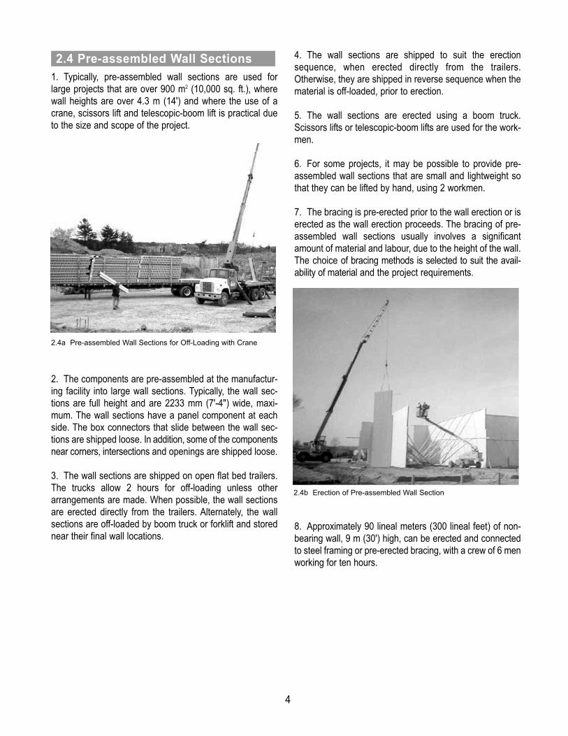
1. Typically, pre-assembled wall sections are used forlarge projects that are over 900 m2 (10,000 sq. ft.), wherewall heights are over 4.3 m (14') and where the use of acrane, scissors lift and telescopic-boom lift is practical dueto the size and scope of the project.
2. The components are pre-assembled at the manufactur-ing facility into large wall sections. Typically, the wall sec-tions are full height and are 2233 mm (7'-4") wide, maxi-mum. The wall sections have a panel component at eachside. The box connectors that slide between the wall sec-tions are shipped loose. In addition, some of the componentsnear corners, intersections and openings are shipped loose.3. The wall sections are shipped on open flat bed trailers.The trucks allow 2 hours for off-loading unless otherarrangements are made. When possible, the wall sectionsare erected directly from the trailers. Alternately, the wallsections are off-loaded by boom truck or forklift and storednear their final wall locations.
4. The wall sections are shipped to suit the erectionsequence, when erected directly from the trailers.Otherwise, they are shipped in reverse sequence when thematerial is off-loaded, prior to erection.5. The wall sections are erected using a boom truck.Scissors lifts or telescopic-boom lifts are used for the work-men.6. For some projects, it may be possible to provide pre-assembled wall sections that are small and lightweight sothat they can be lifted by hand, using 2 workmen.7. The bracing is pre-erected prior to the wall erection or iserected as the wall erection proceeds. The bracing of pre-assembled wall sections usually involves a significantamount of material and labour, due to the height of the wall.The choice of bracing methods is selected to suit the avail-ability of material and the project requirements.
8. Approximately 90 lineal meters (300 lineal feet) of non-bearing wall, 9 m (30') high, can be erected and connectedto steel framing or pre-erected bracing, with a crew of 6 menworking for ten hours.
2.4 Pre-assembled Wall Sections
2.4a Pre-assembled Wall Sections for Off-Loading with Crane
2.4b Erection of Pre-assembled Wall Section
4

1. All of the CONFORM® components that are required foreach project are indicated on the Shipping List and on theErection Drawings. The various CONFORM componentsare identified in Figures 3.1 to 3.4.2. The CONFORM components are precut to the requiredlengths, fabricated to suit the specific project requirementsand labeled to match the erection drawings.3. For walls that are over 6500 mm (21') high, the individ-ual CONFORM boxes and panels are split into two or morelengths. The joints in the boxes and panels are staggerednear mid height. For pre-assembled wall sections, the stag-gered joint is typically 1500 mm (5') high and is not less than900 mm (3'-0"). The panels with the longest length and theboxes with the shortest length are placed at the bottom of thewalls. The horizontal joints in the CONFORM componentsdo not affect the concrete pour and concrete remainsmonolithic. The joints are concealed with an architectural,'multi-storey', band.4. For large projects, CONFORM wall sections are pre-assembled at the manufacturing facility. The maximumwidth of pre-assembled sections is 2233 mm (7'- 4") to suitshipping and handling. The CONFORM components of awall section are screwed together at the webs. For wall sec-tions with staggered joints, the members are screwedtogether on the exterior face, at the staggered joints.5. To avoid delays during erection, spare CONFORM com-ponents are ordered based on the project size, the projectschedule, the site proximity to the manufacturing facility, thepotential for damage on site and the potential for site mod-ifications. The spare pieces include box connectors, panels(P232, P182, P093), spacers (S068 and S049) and boxjoiners. The quantity and type of spare pieces are dis-cussed with a NUFORM® representative to suit each spe-cific project.
3.1 CONFORM® Components
3. Wall Materials
Fig 3.1 CF4 Components
Box Connector: Straight Box Connector: End Box Connector: Corner
Box Connector: 3-way Box Connector: 4-way Box Connector: 45˚
Panel 93 Panel 182 Panel 232
Spacer 49 Spacer 68 Box Joiner
Panel Joiner - Main Panel Joiner - Leg Starter
5
Basic Frame Opening

Fig 3.2 CF6 Components
Box Connector: Straight Box Connector: Corner Box Connector: 45 -̊Outside
Panel 93 Panel 182 Panel 232
Spacer 49 Spacer 68 Box Joiner
Panel Joiner - Main Starter Basic Frame Opening
Fig 3.3 CF8 Components
Box Connector: Straight Box Connector: Corner Box Connector: 45˚-Outside
Panel 93 Panel 182 Panel 232
Spacer 49 Spacer 68 Starter
Basic Window Frame
6

1. The specified 28 day compressive strength of the con-crete is determined by the structural engineer for the proj-ect.2. The concrete mix proportions and the types of aggre-gates are selected to meet the specified strength and toprovide a workability that allows the mix to flow through thecoring without vibration. The workability is dependent onthe cement content, the aggregate size and shape, thewater content and the weather conditions during place-ment.
3. The following mix specification is recommended to meetthe workability requirement:• Specified compressive strength at 28-day of 20 MPa (3000
psi) minimum or 25 MPa (3500 psi) for freeze-thaw con-ditions
• Water to cement ratio of 0.55 maximum. This may pro-vide more cement than required for strength but the high cement content is required for workability.
• Maximum aggregate size of 10 mm (3/8") roundedstone such as pea gravel
• Minimum slump of 100 mm-125 mm (4"-5") at the pointof discharge. Approximately 150 mm (6") at the truck.
• Water reducing admixture• Air entrainment of 5-7% for freeze-thaw conditions,
when applicable4. To achieve the high slump and desired flow, the mix willhave a high cement content and in many cases higher thanis required for the specified compressive strength. Forheavily reinforced walls, the slump may have to be slightlyhigher to ensure that the concrete is in full contact with thereinforcing steel bars in areas of congestion, such as in cor-ners with hooked bars and in lintels with more than onelayer of horizontal reinforcing steel.5. The use of fly ash is not recommended since it tends tocreate a concrete mix that adheres to the inside of theCONFORM components and results in a poor concreteflow.6. The use of plastizers or super-plastizers in the concretemix is not recommended. Often, it is necessary to place theconcrete at a slow pace and the time constraint of a plasti-cizer may not be suitable and may result in poor flowingconcrete and poor consolidation.7. The concrete does not segregate when placed in CON-FORM due to the inner webs of the box connectors andpanel components, which form small cells that act like indi-vidual “elephant trunks” and prevent the “free-fall” of heav-ier aggregates.8. The fluid pressure on the face of the CONFORM com-ponents is significantly less than that experienced with con-ventional formwork. The large number of inner webs andcoring create a bridging action and the numerous jointsbetween the components relieve the pressure by bleedingthe water and cement paste.
3.2 Concrete Mix
Fig 3.4 CF8i Components
Box Connector: Straight Box Connector: Corner Box Connector: 45˚-Outside
Box Connector: 45˚-Inside Panel 93 Panel 182
Panel 232 Spacer 49 Spacer 68
7

9. Internal mechanical vibrators are not recommended foruse with CONFORM since this may cause the faces of theCONFORM components to bow and bulge. To ensure thatthere are no voids and that the concrete is well consolidat-ed, the face of the CONFORM components is externallyvibrated by tapping with rubber mallets or by applying exter-nal mechanical vibrators.10. The quantity of concrete is calculated based on the wallarea and is adjusted for wall openings, wastage and spe-cific project conditions. The theoretical quantities of con-crete for walls with CONFORM are shown in Table 3.1(Metric units) and Table 3.2. (Imperial units).
1. The size and spacing of steel reinforcing bars areselected by the structural engineer for each project to suitthe specific structural requirements.2. The spacing of the vertical reinforcing steel is selectedto suit the spacing of the CONFORM components, whichare based on a 1000 mm (3'-4") grid. A bar spacing of 167,250, 333 and 500 mm (6-1/2", 10", 13" and 20") are com-mon.3. The vertical bars are placed the full height of the wall.
4. The vertical bars are 15M (#5) bars or larger in order tomaintain a straight and plumb bar within the wall. Typically,the vertical bars are placed in the box connectors or in thecenter cell of the P232 panels.5. Wire hoops are tied with 16 ga. wire or tack-welded toeach vertical bar in order to locate the bars at the specifiedlocation from the face of the wall. The wire hoops areplaced at 600 mm (2') from each end and at 3000 mm (10')on center maximum, with a minimum of two hoops per bar.
6. The spacing of the horizontal reinforcing steel is select-ed to suit the spacing of the coring in the webs of the CON-FORM components, which is at 83.3 mm (3-1/4") on center.A bar spacing of 250, 333, 416 and 500 mm (10", 13", 16"and 20") are common.7. Typically, the horizontal bars are placed in lengths up to5500 mm (18') and are installed with laps, as specified onthe structural drawings.8. The horizontal bars are placed through the coring in thewebs of the CONFORM components and are installed afterthe vertical bars are placed.9. Conventional ‘L’ bars cannot be installed at corners andintersections of walls with CONFORM. Therefore, 180°hooked horizontal bars must be installed and a vertical barplaced through the overlapping hooks.
3.3 Steel Reinforcing Bars
3.3 Vertical Rebar with Hoop
Table 3.1: Concrete Take-off (Metric Units)
Table 3.2: Concrete Take-off (Imperial Units)
Per CubicMetre ofConcrete
CF4
11.1 m2
0.0903 m3
Square Metre of Wall AreaCF6
7.2 m2
0.1385 m3
CF8
5.4 m2
0.1867 m3
CF8i
7.5 m2
0.1336 m3Per SquareMetre of Wall Area
Per Cubic Yard ofConcrete
CF4
91 ft2
0.0110 yd3
Square Foot of Wall Area
Cubic Yard of Concrete
CF6
59 ft2
0.0169 yd3
CF8
44 ft2
0.0227 yd3
CF8i
61 ft2
0.0164 yd3Per SquareFoot of Wall Area
8
Cubic Metre of Concrete

10. The 180° hooks for horizontal bars are bent using thepin diameters used for stirrups and ties. The 180° hooksmust fit through the coring in the webs of the CONFORMcomponents. Refer to the CONFORM Engineering Guide.11. Where ‘L’ bars are essential at the corners, they can beinstalled by using a threaded mechanical splice at the bendof the ‘L’ bar.
1. The required fasteners depend on the specific projectand may include:• Fasteners for CONFORM components • 1-1/2" Common Nails (for formwork plywood)• 3" Double Headed Nails (for bracing and forming lumber)• 3" Common Nails (for bracing and forming lumber)
2. The required bracing materials depend on the erectionand bracing methods selected for the specific project andmay include:• Nominal 2x4, 2x6, 2x8, 2x10 and 4x4 Framing Lumber
(for bracing and formwork)• 1/2" OSB Sheathing (for formwork)• 3/4" Rough Spruce or Pine Plywood Sheathing
(for formwork)• Form Brace Aligners (for rakers)• Slotted Steel Channels and Fittings (for small projects)• Cold Formed Steel Angle 2"x2"x18 ga (for small projects) • Steel Angle 3x2x3/16" (for large projects)• Bakers Scaffold w/Wheels (for erection of small projects)• Heavy Duty Scaffolding (for erection and shoring
of large projects)• I Beams (for shoring of large projects)• Post Jacks (for shoring of large projects)
3. The other items that may be required for a specific project include:• Cleaners and Patching Materials (refer to Section 13 and
14)• Paints and Cladding Materials (refer to Section 15)• Oxime Neutral Cure Silicone Sealant (refer to Section 13)• Wire Hoops and Tie Wire• AIFB (Ten-test)• Polystyrene or Polyurethane Insulation Boards (to form
pockets and expansion joints)• Foundation Drainage Mat (as supplied by NUFORM®)• Miscellaneous Construction Materials
3.4 Fasteners, Bracing, Others
9
1. The hand tools used on most projects:• Measuring Tapes (7.5 m/25') and (30 m/100')• 100' Chalk Reel & Chalk• 48" Aluminum Hand Level • 16" x 24" Carpenter’s Square• 20 oz Claw Hammers• 28 oz White Rubber Mallets• 10 lb or 20 lb Sledge Hammer• Utility Knife and Blades• Hack Saw and Blades• 24" Carpenter’s Hand Saw (Crosscut, 10 TPI)• Screwdriver Sets (Slot, Phillips, Robertson)• 3/4" x 8" Concrete Chisel• 7" Wire Cutters• 8" Linesman Pliers• 12" Adjustable Wrench• 8" Aluminum Hand Trowel• Caulking gun
2. The additional hand tools used for small projects:• Plumb Bob• Mason String Line• 12" Combination Square• 4 in 1 Carpenter’s File• Wood Chisel Set (1/4", 1/2", 3/4", 1")• Carpenter’s Block Plane• 9-3/4" Straight Metal Snips• 10" Vice Grips• 24" Bar Clamps or Quick-Grip Clamps• Rivet Gun (1/8"ø x 1/2" aluminum rivets)
3. The additional hand tools used for large projects:• Surveyor’s Level• Surveyor’s Laser Transit• 20"x 14" Carpenter’s Clamps• 3/8" x 100' Rope
1. The power tools required on most projects:• 3/8" Cordless Drill Kits and Spare Batteries (14.4V min.)• Extension Cords and Power Bars• 1/2" Electric Impact Drill• HSS Drill Bits (1/16"ø to 1/2"ø)• Magnetic, 6" Round Shaft, Driver Bits
(Phillips, Robertson #1 & #2, Socket)
• Hole Saw Kit (3/4"ø to 2-1/2"ø)• 1-1/2" Rotary Hammer Drill (for dowels)• Concrete Drill Bits (5/32", 3/16", 3/4", 1")• Heat Gun• 7-1/4" or 8" Circular Saw (60 Teeth Blades)• Reciprocating Saw (14 TPI x 8" Blades)• 4-1/2" or 5" Grinder (grinding discs)• 12" or 14" Gas Powered Quick Cut Saw
(Metal & Concrete Blades)• 3000 psi Power Washer (with heater for hot water
in winter)• Gas Powered Generator (2500 watt)• Jig Saw (18 TPI Blades)• 10" or 12" Sliding Compound Mitre Saw
(with 72 Teeth blades)
1. The erection equipment used on most projects:• Aluminum Step Ladders (4', 8' or 12')• Baker’s Scaffold or Aluminum Scaffold• Concrete Funnel (CF4, CF6, CF8/8i)• Concrete Bucket (1/2 yard)• Push Brooms and Corn Brooms• 6' Scraper• Square Shovel• Wheelbarrow• Soft Bristle Brushes for Washing• 100' Garden Hose with Spray Nozzle
2. The additional erection equipment used for large projects:• Surveyor’s Laser Transit for Vertical Line• Extension Ladder (20' or 30')• 3/8" x 250' Rope• Strapping Equipment and Strapping Refills• Lifting Bar (15/16"ø x 9' smooth bar) • Lifting Chains (2 hooks and 8' chains)
1. The construction equipment used on most projects:• 34 m Concrete Pump with 3" or 4" reducer and S-bend
2. The additional construction equipment used for large projects:• Scissors Lift (40' platform)• Telescopic-Boom Lift (60' arm) or a second Scissors Lift• Telescopic Fork Lift (40' arm)• Boom Truck (1200 lb capacity at 70')• MIG Welder with electrodes, mask and gloves
4.4 Construction Equipment
4.3 Erection Equipment
4.2 Power Tools
4.1 Hand Tools
4. Equipment
10

11
1. All workmen must follow the applicable constructionsafety rules and regulations to operate all equipment andtools and to perform all work.2. Workmen shall not travel or work below any wall sec-tions or components that are lifted overhead by a boomtruck or workmen.3. Workmen wear construction gloves to handle the CON-FORM® material. The edges of the coring and the ends ofthe components are hazardous. 4. The components must not be held through the coringwhen slid together. The coring in the webs creates a sharpshear as the components are slid together and can causeserious injury.5. Workmen working off the ground or on elevated plat-forms must wear the appropriate safety harnesses.
1. The CONFORM components are not affected by weath-er conditions. However, long components or pre-assem-bled panels are not erected in adverse weather conditions forsafety reasons. Short walls and sill walls may be erected inmost weather conditions.2. CONFORM must not be erected in high winds since thecomponents and wall sections cannot be handled safely bythe workmen.3. The walls are not erected in icy or snowy conditionswhere the workmen have poor footing conditions.4. The appropriate lateral bracing for stability and windconditions must be installed as the CONFORM compo-nents are erected. The lateral bracing must remain in placeuntil the concrete is cured and the permanent bracing orstructural framing is attached.
5.2 Weather Conditions5.1 Workmen
5. Safety
5.1 Bearing Wall Project

12
1. The ground at the exterior and interior of the building isgraded to a level surface for equipment access during erec-tion of the walls. Typically, the ground is graded to the fin-ished sub-base elevation specified for the exterior pavingand the interior floor slab, but not higher than 150 mm (6")below the top of the foundation wall or footings. 2. Depending on method of erection, individual componentor pre-assembled wall sections, the ground may have to begraded level for at least 6 m (20') wide at the exterior andinterior side of the foundation wall. In the case of panelizedwalls, it is recommended that the width at the exterior sideof the foundation wall be 15 m (50'). This is to allow 4.5 m(15') for a scissors lift or telescopic boom lift, 6 m (20') for aboom truck to lift the panels and 4.5 m (15 ft) for trucks todeliver the panels.
1. A secure area is required on site for storage of all mate-rial and equipment. The size of the area depends on the sizeof the project, the delivery schedule for material and theequipment being used for erection. The storage is selectedto keep the components as clean, as possible. If the groovesof the panels become dirty, the components will not slidetogether easily.2. Care is taken to avoid damaging the finished surface ofthe CONFORM® components. Individual box connectorsand panels are stacked on their edges (cored side down) toprevent damage and scratches to the finished faces. Thecomponents are never stored on the finished faces andcomponents are never dragged on their faces or draggedover the face of another component.
3. The labeling is noted during off-loading and similar com-ponents are stacked together. When practical, a separatepile is created for each different length of each differentindividual component and the labels are placed at the sameend. The piles are placed in close proximity to the areawhere the material will be installed. The labels are placedat the top of the components and for flat walls the first holeof the coring is 37 mm (1-1/2") from the top end.4. The individual components are stacked in a level con-figuration, one on top of the other. The components areplaced on leveled wood sleepers that are spaced at 1.5m(5') on center, maximum. The components have a tenden-cy to deform if they are stored with uneven or insufficientsupport. The flat straight piles are not more than 1200 mm(4') high by 1200 mm (4') wide and the piles are braced forstability.
5. When daily temperatures are consistently over 30°C(86°F), the material should be stored in the shade or cov-ered with loose tarps that provide shade but do not restrictthe air flow. CONFORM material must not be stored inclosed containers or tightly wrapped with tarps or plasticwrap, since this will increase temperatures and may resultin deformation of the components.
6.2 Storage of Material
6.1 Site Grading and Access
6. Site Preparations
6.2a Storage of Individual Components
13
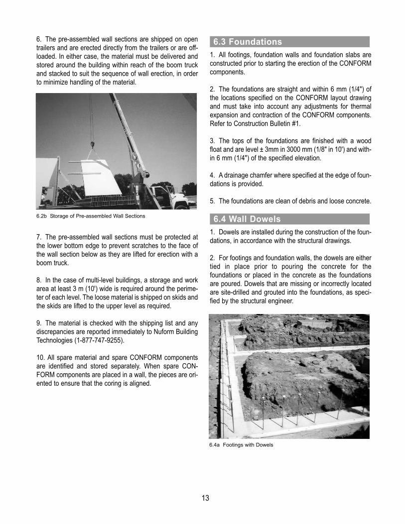
6. The pre-assembled wall sections are shipped on opentrailers and are erected directly from the trailers or are off-loaded. In either case, the material must be delivered andstored around the building within reach of the boom truckand stacked to suit the sequence of wall erection, in orderto minimize handling of the material.
7. The pre-assembled wall sections must be protected atthe lower bottom edge to prevent scratches to the face ofthe wall section below as they are lifted for erection with aboom truck.8. In the case of multi-level buildings, a storage and workarea at least 3 m (10') wide is required around the perime-ter of each level. The loose material is shipped on skids andthe skids are lifted to the upper level as required.9. The material is checked with the shipping list and any discrepancies are reported immediately to Nuform BuildingTechnologies (1-877-747-9255).10. All spare material and spare CONFORM componentsare identified and stored separately. When spare CON-FORM components are placed in a wall, the pieces are ori-ented to ensure that the coring is aligned.
1. All footings, foundation walls and foundation slabs areconstructed prior to starting the erection of the CONFORMcomponents. 2. The foundations are straight and within 6 mm (1/4") ofthe locations specified on the CONFORM layout drawingand must take into account any adjustments for thermalexpansion and contraction of the CONFORM components.Refer to Construction Bulletin #1.3. The tops of the foundations are finished with a woodfloat and are level ± 3mm in 3000 mm (1/8" in 10') and with-in 6 mm (1/4") of the specified elevation.4. A drainage chamfer where specified at the edge of foun-dations is provided.5. The foundations are clean of debris and loose concrete.
1. Dowels are installed during the construction of the foun-dations, in accordance with the structural drawings. 2. For footings and foundation walls, the dowels are either tied in place prior to pouring the concrete for the foundations or placed in the concrete as the foundationsare poured. Dowels that are missing or incorrectly locatedare site-drilled and grouted into the foundations, as speci-fied by the structural engineer.
6.4 Wall Dowels
6.3 Foundations
6.2b Storage of Pre-assembled Wall Sections
6.4a Footings with Dowels

14
3. For monolithic foundation and floor slabs, the dowels are placed in holes that are drilled into the slab and filled with epoxy or cementious grout, as specified by the struc-tural engineer.
4. The dowels are located accurately to suit the CON-FORM components. The dowels are placed within 20 mm(3/4") of the center of box connectors and panels in order toavoid interference with the webs of the CONFORM compo-nents.5. The locations of the dowels at each side of door open-ings are critical and must be accurately located.
1. All underground and in-slab plumbing is installed prior topouring the foundation slab.2. All underground and in-slab electrical wiring is installedprior to pouring the foundation slab. Electrical conduit isinstalled below the foundation slab to suit the distribution of wiring to the walls or CONFORM service channels.
1. Hand tools for workmen are battery operated whenever possible.2. Portable generators are recommended for site power inorder to provide accessibility at all locations and to mini-mize the length of extension cords.
1. A water supply, hoses and washing nozzles are requiredfor cleaning the walls during concrete placement. 2. A power washer is recommended to clean the walls with a pressure of 3000 psi. 3. For small projects, the power washer is connected to awater tap and for large projects it is connected to a watertruck. 4. Hot water is used in cold weather construction.
6.7 Water Supply
6.6 Electrical Power
6.5 Underground Services
6.4b Foundation Slab with Dowels
15
1. CONFORM® is a pre-finished concrete wall form-work. Additional painting or veneers are not required.CONFORM material is handled and treated as a “pre-finished” product to avoid unnecessary damage ormarring of the surface or the components.2. The CONFORM components are pre-cut to length asrequired for each project. However, some components mayneed to be site cut if there are field changes to suit site con-ditions, or to revise the openings for door and windows.3. Experienced concrete or formwork installers are trainedto become familiar with the various CONFORM compo-nents and the labeling system used on the CONFORMassembly drawings. Each component is specifically labeledfor a location within the wall. During erection, one person isassigned to locate and coordinate the components or wallsections consecutively, in accordance with the CONFORMerection drawings.4. CONFORM components are installed with the“labeled end” up. This allows verification during assem-bly of the component locations and also maintains thealignment of coring for proper flow of concrete betweenthe components. Assembling a component upside-down will cause the coring to be mis-aligned and con-crete will not flow properly between the wall compo-nents.5. The component sequence and orientation is checkedand re-checked throughout the assembly. The removal and re-assembly of wall components due to incorrect sequenceor orientation can significantly delay the erection.6. The CONFORM components must be visuallyinspected for damage or breaks to the web between thecoring. Any CONFORM components with a broken webmust be replaced or repaired, since the webs hold thetwo faces of the wall together during placement of con-crete. Damage or a break of one web will result in abulge in the wall face and damage to two or three webcan result in a blowout.
7. During extremely cold temperatures, avoid dropping theCONFORM components as fractures to the ends andbreaks in the webs may occur.8. Bracing is required to hold the top and bottom of the wallas the components are assembled. For high walls, addi-tional bracing is required at mid-height. Refer to the brac-ing section to ensure proper materials are on-site beforestarting the wall erection.9. The installation of CONFORM components requires afoundation or floor by others. The foundation must have therequired reinforcing dowels accurately located in accor-dance with the structural drawings and the CONFORMdrawings.
1. The dimensions of the foundation and square of thefoundation are verified with respect CONFORM layoutdrawings, including any adjustments for thermal expansionand contraction. Refer to Construction Bulletin #1. 2. The elevation and levelness of the top of the foundationare verified to ensure that the foundations are suitable forCONFORM and that elevation changes are provided wherespecified.3. The location of one face of each wall is measured asaccurately as possible, + 3 mm (+ 1/8"), and marked on thetop of the foundation using a chalk line. All measurementsalong a wall are taken cumulatively from one corner inorder to obtain accurate locations. A 3:4:5 triangle is usedto ensure that corners are square. Where possible, thediagonals are measured from corner to corner and madeequal to ensure the layout is square.4. Each side of all openings is measured and marked onthe top of the foundation.
7.2 Layout
7.1 Orientation
7. Wall Erection - General
16
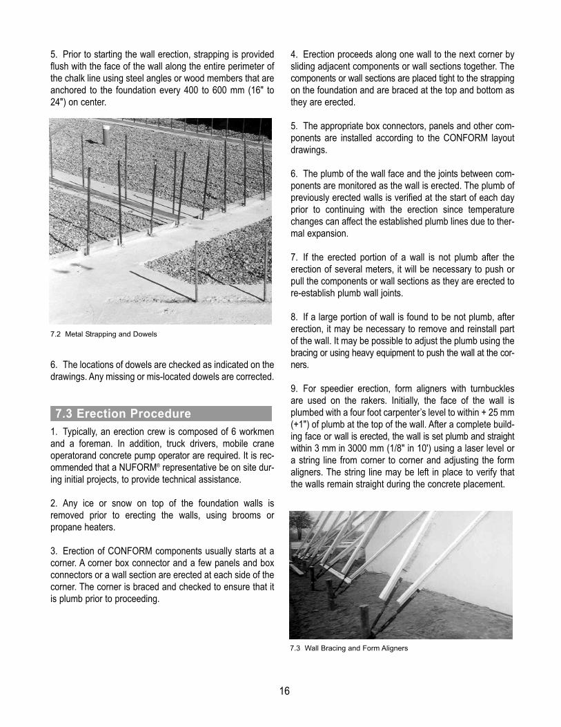
5. Prior to starting the wall erection, strapping is providedflush with the face of the wall along the entire perimeter ofthe chalk line using steel angles or wood members that areanchored to the foundation every 400 to 600 mm (16" to24") on center.
6. The locations of dowels are checked as indicated on thedrawings. Any missing or mis-located dowels are corrected.
1. Typically, an erection crew is composed of 6 workmenand a foreman. In addition, truck drivers, mobile craneoperatorand concrete pump operator are required. It is rec-ommended that a NUFORM® representative be on site dur-ing initial projects, to provide technical assistance.2. Any ice or snow on top of the foundation walls isremoved prior to erecting the walls, using brooms orpropane heaters.3. Erection of CONFORM components usually starts at acorner. A corner box connector and a few panels and boxconnectors or a wall section are erected at each side of thecorner. The corner is braced and checked to ensure that itis plumb prior to proceeding.
4. Erection proceeds along one wall to the next corner bysliding adjacent components or wall sections together. Thecomponents or wall sections are placed tight to the strappingon the foundation and are braced at the top and bottom asthey are erected.5. The appropriate box connectors, panels and other com-ponents are installed according to the CONFORM layoutdrawings.6. The plumb of the wall face and the joints between com-ponents are monitored as the wall is erected. The plumb ofpreviously erected walls is verified at the start of each dayprior to continuing with the erection since temperaturechanges can affect the established plumb lines due to ther-mal expansion.7. If the erected portion of a wall is not plumb after theerection of several meters, it will be necessary to push orpull the components or wall sections as they are erected tore-establish plumb wall joints.8. If a large portion of wall is found to be not plumb, after erection, it may be necessary to remove and reinstall partof the wall. It may be possible to adjust the plumb using thebracing or using heavy equipment to push the wall at the cor-ners. 9. For speedier erection, form aligners with turnbucklesare used on the rakers. Initially, the face of the wall isplumbed with a four foot carpenter’s level to within + 25 mm(+1") of plumb at the top of the wall. After a complete build-ing face or wall is erected, the wall is set plumb and straightwithin 3 mm in 3000 mm (1/8" in 10') using a laser level ora string line from corner to corner and adjusting the formaligners. The string line may be left in place to verify thatthe walls remain straight during the concrete placement.
7.3 Erection Procedure
7.2 Metal Strapping and Dowels
7.3 Wall Bracing and Form Aligners

17
10. The cleanliness of the components and especially thebox connector legs and panel grooves will affect the slidingof the panels. The components are kept clean and anyobvious dirt wiped away.11. If difficulty is encountered in sliding the components, the joints are lubricated by spraying the leg or groove with a silicone lubricant or a vinyl protectant (such as Armor-All).If the components are difficult to slide, they are hit at the topwith a sledge hammer or a demolition gun but using a woodblock to protect the end of the component. Excessive forcemust not be used with the hammer or the components willbreak or chip. Use sufficient force to achieve a 25 mm to 50mm (1" to 2") drop per blow. Also, refer to ConstructionBulletin #2.
1. The CONFORM components have a tolerance of 0.5mm (1/32") at each joint but this varies depending on thetemperature, the straightness of the components, theheight of the wall and the type of component.2. Due to the large number of joints, this tolerance allowsthe length of the wall to be adjusted by pushing and pullingon the components as they are erected. In this manner it is possible to keep the wall length close to the specifiedlength indicated on the CONFORM drawings and to keepthe joints plumb. Tapping or shaking the bottom of the wallwill aid in adjusting the wall length.3. High temperatures or low temperatures affect the hori-zontal length of the walls. The theoretical wall length will vary2.9 mm in 5000 mm for each 10°C (1/8" in 16' for each 20°F)variation in temperature. The theoretical dimensions on theCONFORM drawings are calculated at 20°C (68°F).4. When the erection is within approximately 1.5 m (5') ofa corner or a large opening, the wall length remaining ismeasured at the top and bottom of the wall and verified withthe supplied components or wall sections. Metric dimen-sions are used to determine the acceptability of the remain-ing components since the imperial dimensions for compo-nents are rounded to the nearest fraction. The wall isplumbed if the top and bottom dimensions are not equal.
5. The components or wall sections are adjusted adjacentto a corner or a large opening, using spacers and smallpanels to suit the required dimension. Refer to ConstructionBulletin #3 to determine the components required to suita specific dimension.
1. Starters are used to create T-intersections except for theCF4 wall. Refer to Construction Bulletin #15.2. Usually, starters are assembled to the adjacent compo-nents, prior to starting the wall erection. A starter is orient-ed on the adjacent components so that the coring holes will be aligned.3. The web of the starter is connected to the face of theadjacent components with 1/8" ø x 1/2" long aluminum poprivets. The pop rivets are located 20 mm (3/4") from eachside of the starter and centered between each second cor-ing hole, at 167 mm (6-5/8") on center.4. Holes are cut in the face of the adjacent component tomatch the coring holes in the starter.
5. Alternately, the starter is temporarily held in place inorder to cut the coring holes in the face of the adjacentcomponent. Then, the starter is slid onto the next panel andboth the starter and the panel connected to the adjacentcomponent, by reaching through the coring to install #10 x3/4" screws, at the same spacing specified for pop rivets.
7.5 Starters
7.4 Wall Length
7.5 Starter Installation

18
1. CONFORM is installed to one side of a wall opening.The sill components are installed and the first 2 or 3 com-ponents or wall section at the other side of the wall open-ings are installed. The coring is checked to ensure that it isaligned.2. At door openings, temporary wood blocking is anchoredto the foundations at each side of the opening to maintainthe correct opening width and location.3. All horizontal steel reinforcing bars that are requiredadjacent to an opening must be placed in the wall prior toinstalling door frames. 4. Wrap-around hollow metal frames, if required, areinstalled before the header above the opening.5. Steel overhead door frames, if required, are erectedprior to starting the erection of CONFORM. The frames areanchored to the foundations and held in place with tempo-rary steel or wood bracing.
6. When steel lintels are specified, a "cut out" to match thelintel shape is site cut into the web of the box or panel adja-cent to the opening. The height for the underside of thesteel lintel can be determined by temporarily installing acomponent from the header and scribing a line on the webat each side of the opening. The lintel is lifted into positionand inserted into the "cut-out" in the two side components.The header components are pre-fabricated to suit the lintel,if requested.
7. The header components are pre-assembled and thewebs are connected together. The header is installedbetween the two side components and is held in place byscrewing the webs at the ends of the header to the webs ofthe side components. For large headers, at least one T-support is provided initially, until the temporary bracing isinstalled to support the weight of wet concrete to be placedin the header.
7.6 Doors, Windows, Openings
7.6a Overhead Door Frame Installation
7.6b Steel lintel Installation
19
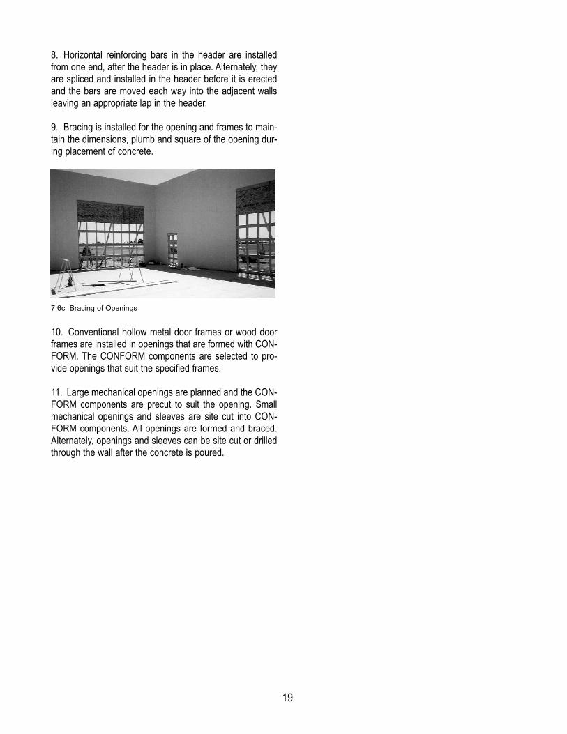
8. Horizontal reinforcing bars in the header are installedfrom one end, after the header is in place. Alternately, theyare spliced and installed in the header before it is erectedand the bars are moved each way into the adjacent wallsleaving an appropriate lap in the header. 9. Bracing is installed for the opening and frames to main-tain the dimensions, plumb and square of the opening dur-ing placement of concrete.
10. Conventional hollow metal door frames or wood doorframes are installed in openings that are formed with CON-FORM. The CONFORM components are selected to pro-vide openings that suit the specified frames.11. Large mechanical openings are planned and the CON-FORM components are precut to suit the opening. Smallmechanical openings and sleeves are site cut into CON-FORM components. All openings are formed and braced.Alternately, openings and sleeves can be site cut or drilledthrough the wall after the concrete is poured.
7.6c Bracing of Openings

20
1. For conventional electrical wiring, masonry electricalboxes and rigid or flexible conduit are installed in the com-ponents as the wall is erected. The electrical boxes areplaced in the center of the box connectors and panels.
2. A CONFORM non-metallic service channel is used forlow voltage wiring and communication cables. The loca-tions of all service channels are pre-determined and notedon the CONFORM erection drawings. During erection,service channels are installed in box connectors or in pan-els using the channel adapter. The channels are full heightand the tops of the channels are sealed with duct tape. Thechannels are checked to ensure they are sealed during theconcrete placement. The locations of the channels aremarked on the face of the box connectors with tape, forfuture reference.
3. For industrial projects, the electrical boxes and wiringare surface mounted in the same manner as conventionalconcrete or masonry walls.
7.7 Electrical
7.7a Electrical Box and Conduit
7.7b Electrical Box Installation
7.7c CONFORM Service Channel

21
1. The individual components have a distinctive topand bottom orientation, which must be maintained inorder for the coring to be aligned. Typically on flat cutwalls, the top of the first coring hole is 37 mm (1-1/2") fromthe top of the wall. During erection the top of the compo-nents must be identified to ensure that all coring is alignedwithin 10 mm (3/8").2. The individual components are erected sequentially bytwo workmen, one working on the ground and one workingon a scaffold or man-lift. The panels are placed on the foun-dations and the box connectors are lifted to the top of thepanels. The box connector legs are aligned with thegrooves in the panels and the box connectors are slid downto the bottom of the panels.3. Typically, a box connector is guided 100 mm (4") ontothe top of a panel. Then, both the box connector and panelare lifted together to connect the legs at the other side ofthe box connector into the grooves of the panel that waserected previously. The box connector is slid down betweenthe existing panel and the new panel. The new panel is held25 mm (1") above the foundation as the box connector islowered into place.
4. The installation of the last component between two partsof a wall can be made easier by lifting one of the adjacentcomponents, approximately 900 mm (3'). One side of the lastcomponent is slid onto the lifted component and the otherside of the last component is connected to the wall by pullingor pushing on the end of the last component. Then, the lastcomponent and the adjacent component are slid down tothe foundations.
1. Erection is started with a box connector at a corner or a T-intersection and the two adjacent panels. The compo-nents are located on the foundation adjacent to the strap-ping.2. The corner box connector or three way box connectoris lifted and guided 100 mm (4") onto the top of one panel.3. These two components are lifted together to allow thebox connector to be joined onto the top of the other panel.The box connector is slid down between the two panels andis located over the foundation dowel.
8.2 Erection Sequence
8.1 Erection Procedure
8. Wall Erection - Individual Components
8.1 Erection of CONFORM® Box and Panel
8.2a Erection of CONFORM Corner

22
4. The pieces are checked to ensure that the correct components are installed and properly oriented and that thecoring is aligned.5. Additional components are added at each side of the cor-ner or T-intersection for a distance of 667 mm (2' 2") as per Item 8.1.3.6. Bracing is provided at the top and bottom of the corneror T-intersection assembly and the components arescrewed together at the top after the assembly is accurate-ly plumbed.7. The erection of CONFORM components is continuedsequentially, in accordance with the CONFORM layoutdrawings, including the components for doors, windowsand openings.
8. The wall erection is continually monitored to ensure the correct component sequence and alignment of coring. 9. Measurements are taken along the length of the wall toensure that the dimensions are maintained in accordancewith the CONFORM drawings. The components are pulledor pushed together as the erection proceeds to ensure thespecified dimensions are achieved.
10. Temporary bracing and steel reinforcing bars areinstalled as the wall erection proceeds.11. If horizontal hooked corner bars are required, refer toSection 10, Steel Reinforcing Placement, for the erection of corners and intersections.12. The other corners and T- intersections are preciselylocated to suit the CONFORM layout. As the erection iscompleted at a corner or T-intersection, the wall is pushedor pulled to ensure that the corner or T-intersection is at thecorrect location.
8.2b Erection of CONFORM

23
1. Typically, the pre-assembled wall sections are erectedusing an overhead crane with a capacity to lift a full wallsection to the top of the wall, so that the wall section is slidinto place using its own weight.2. An erection crew is composed of 5 workmen and a fore-man. In addition, a crane operator and truck drivers arerequired. During lifting, two workmen are required to holdropes at the base of the wall sections. Two workmen arerequired on scissors lifts or telescopic lifts to guide the wallsections in place, to connect the bracing, to install individ-ual components between wall sections and to install rein-forcing bars. One workman is required to guide the panels atthe bottom, to handle the bracing materials and to handlethe individual components.
3. The pre-assembled wall sections have unique locationsand orientations that must be maintained in accordancewith the CONFORM® layout drawings. Also, the top of eachwall section must be identified in order for the coring to bealigned.4. Typically, the pre-assembled wall sections have a panelat each side and an individual box connector is slidbetween two wall sections to erect the wall.
5. The pre-assembled wall sections are inspectedprior to lifting to ensure that all components aresecured to each other and especially that the lowercomponents below a staggered joint are adequatelyconnected to the upper components that contain thehoisting bar.
6. Prior to lifting, all dirt or ice is removed from the groovesof the panels at each side of a wall section and the groovesare lubricated, as necessary.7. A 23.8 mm (15/16") diameter hoisting bar is placed inthe second core from the top of the wall section. Chainsand hooks are connected to the hoisting bar at approximately375 mm (15") from each side of the wall section. If slings areused, a spreader bar is provided to prevent distortion at the topof the wall sections.8. The wall sections are shipped with strips of padding atthe bottom of each section to prevent scratching the face ofthe wall section below when they are lifted using a crane.9. Two 7.5 m (25 ft) long ropes are connected to the bot-tom corners of the wall sections prior to lifting and are heldby workmen at all times. The ropes are hooked through ortied to the coring at the second web from the sides the wallsections.
9.1 Erection Procedure
9. Wall Erection - Pre-assembled Wall Sections
9.1a Erection of Pre-assembled Wall Section
9.1b Screws at Staggered Joint

24
10. Workmen never walk under a wall section lifted by a crane.11. A box connector is installed before erection of the nextwall section. Alternately, a 103 mm (4-1/16") wood spaceris placed adjacent to the web of a previously erected wall sec-tion to provide the appropriate space for a box connectorbetween the panels at each side.12. A wall section is lifted adjacent to the dowels in thefoundation. If the dowels will interfere with the webs of thecomponents, the dowels are bent a minimum of 12 mm(1/2") away from the webs to allow for final adjustment ofthe wall section. The wall section is lifted away from thefoundation prior to workers bending the dowels.13. Workmen shall never place their hands between awall section and a dowel or between two wall sections.A sudden gust of wind will move the wall sections in anunexpected manner.14. The wall section is lifted above the dowels or the adja-cent box connector and lowered into the correct positionadjacent to the strapping or angle on the foundation.
15. The individual component or components are installedon the previous wall section before the next wall section iserected. The individual components are installed using ascissors lift or zoom-boom lift.
16. Bracing and sufficient temporary anchors are connect-ed to each wall section prior to removing the slings and the hoisting bar.17. As each wall section is erected, the bracing andanchors are completed as required to safely support thewall.18. The exposed screws on the faces of the wall that wereused to secure the components to each other at a stag-gered joint are removed once the bracing is completed. Inspecial cases, it may be necessary to remove these screwsto plumb the wall components, after the wall section isplaced on the foundations.
1. Individual components are provided to join wall sectionstogether and construct short lengths of walls near cornersand openings.2. Typically, an individual box connector component isinstalled between wall sections. However, for a wall sectionwith a finger joint, the lower part of the wall is joined with abox connector and the upper part of the wall is joined with a panel, a box connector and another panel. 3. Workmen on a scissors lift or zoom-boom lift install theconnecting components. The components are lifted by aworkman at the top and guided together by a workman atthe bottom. Both workmen carefully slide the componentsdown.4. Also, refer to Section 8.
9.2 Individual Components
9.1c Pre-assembled Wall Section Lowered over Dowels

25
1. Start the erection of pre-assembled wall sections at one corner of a building and proceed around the building in a sequential manner. Typically, the erection is completedfor sequential rectangular elements where interior wallsdivide the building into several areas or bays. The last wallsection of each rectangle may be completed adjacent to anopening to assist in the placing of horizontal reinforcingsteel.
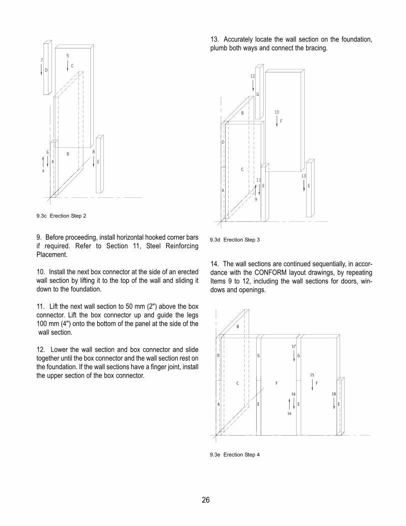
2. Place the appropriate corner box connector in a corner.3. Lift one of the adjacent wall sections to 50 mm (2")above the corner box. Lift the corner box up and guide thelegs 100 mm (4") onto the bottom of the panel at the side atthe wall section.4. Lower the wall section and corner box and slide togeth-er until the corner box and the wall section rest on the foun-dation.5. Accurately locate the wall section on the foundation,plumb both ways and connect the bracing.
6. In a similar manner, lift the other adjacent wall section to50 mm (2") above the corner box. Lift the corner box up andguide the legs 100 mm (4") onto the bottom of the panel atthe side of the wall section.7. Lower the wall section and corner box. Slide togetheruntil the corner box and the wall section rest on the foun-dation. If the wall sections have a finger joint, install theupper section of the corner box.8. Accurately locate the wall section on the foundation,plumb both ways and connect the bracing.
9.3 Erection Sequence
1
3 8
6
5
4 7
BUILDING PLAN
2 10 9
B
2
A
3
1
9.3a Erection Sequence for Wall Sections
9.3b Erection Step 1
26
9. Before proceeding, install horizontal hooked corner barsif required. Refer to Section 11, Steel ReinforcingPlacement. 10. Install the next box connector at the side of an erectedwall section by lifting it to the top of the wall and sliding itdown to the foundation.11. Lift the next wall section to 50 mm (2") above the box connector. Lift the box connector up and guide the legs 100 mm (4") onto the bottom of the panel at the side of thewall section.
12. Lower the wall section and box connector and slide together until the box connector and the wall section rest onthe foundation. If the wall sections have a finger joint, installthe upper section of the box connector.
13. Accurately locate the wall section on the foundation,plumb both ways and connect the bracing.
14. The wall sections are continued sequentially, in accor-dance with the CONFORM layout drawings, by repeatingItems 9 to 12, including the wall sections for doors, win-dows and openings.
D
A
12
9
10
11
G
13
B
F
C
E E
D
A
17
14
15
F
E E
16
G G
18
B
E
FC
A E
DC
75
6 8
4
B
9.3c Erection Step 2
9.3d Erection Step 3
9.3e Erection Step 4
27
15. For ease of erection, it is possible to pre-install the nextbox connector on a wall section before it is lifted for erec-tion. This eliminates lifting the next box connector to the topof a wall section and sliding it down full height. Refer to Item10. The box connector is slid onto the wall section prior toerection and is held in place using temporary screwsthrough the box connector web or leg. The temporaryscrews are removed after erection so that the box connec-tor can be lifted up onto the bottom of the next wall section.Refer to Item 11.16. Temporary bracing and steel reinforcing bars areinstalled as the wall erection proceeds.17. The wall erection is continually monitored to ensure theproper wall section sequence, component sequence andalignment of coring.18. Measurements are taken along the length of the wall toensure that the dimensions are maintained in accordancewith the CONFORM drawings and that the wall sections areplumb in both directions. The wall sections are pulled orpushed together as the erection proceeds to ensure thespecified dimensions and plumb are achieved. 19. Individual components are often used adjacent to cor-ners, wall intersections, doors, windows and openings inorder to achieve the specified dimensions. The spare com-ponents are substituted for some or all of the individualcomponents where necessary to ensure that the specifieddimensions are met. If required, some components areremoved from the side of a pre-assembled wall section andspare components installed to suit the specified dimen-sions.
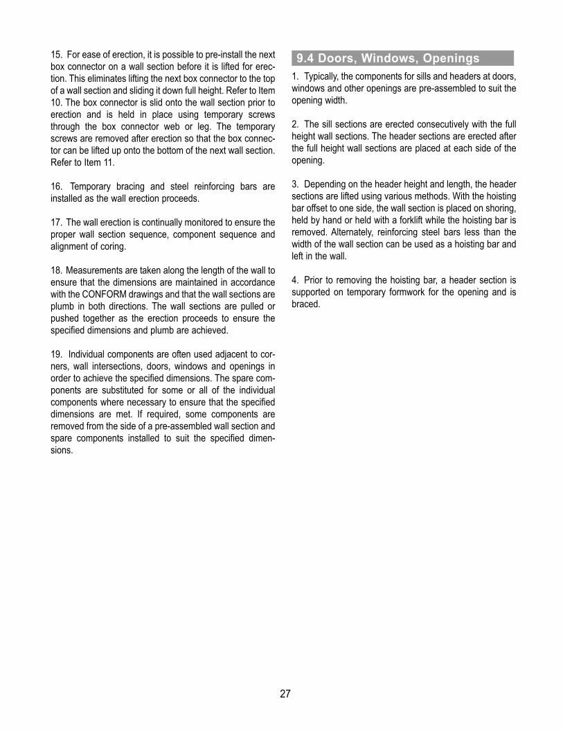
1. Typically, the components for sills and headers at doors,windows and other openings are pre-assembled to suit theopening width. 2. The sill sections are erected consecutively with the fullheight wall sections. The header sections are erected afterthe full height wall sections are placed at each side of theopening. 3. Depending on the header height and length, the headersections are lifted using various methods. With the hoistingbar offset to one side, the wall section is placed on shoring,held by hand or held with a forklift while the hoisting bar isremoved. Alternately, reinforcing steel bars less than thewidth of the wall section can be used as a hoisting bar andleft in the wall.4. Prior to removing the hoisting bar, a header section issupported on temporary formwork for the opening and isbraced.
9.4 Doors, Windows, Openings
28
1. Reinforcing steel bars are provided as specified on thestructural drawings for the project.2. Vertical bars are provided 25 mm (1") less than theheight of the wall. The vertical bars are placed in the boxconnectors or in the cells of the panels. Wire hoops are tackwelded or tie wired to the bars at 600 mm (2') from eachend and at 3 m (10') maximum, with a minimum of twohoops per bar. The hoops are sized to suit the diagonaldimension of the box connector and are bent lightly whenused in a panel. The hoops are located on the bars to suitthe specified location of the bars within the width of the wall.3. Typically, the vertical bars are erected as the wall erec-
tion proceeds and must be installed prior to the horizontalbars, except at corners.4. If specified, the vertical bars are tied to the foundationdowels by lifting the box connectors approximately 12".This must be done prior to placing the horizontal bars.
5. In some cases, the vertical bars are tied to the founda-tion dowels prior to erecting the CONFORM® componentsand the box connectors are lifted over the top of the verti-cal bars.6. Horizontal bars are installed after the vertical bars andare placed through the coring in the CONFORM compo-nents. The recommended length for a horizontal bar is5500 mm (18'). The horizontal bars are installed after each4667 mm (16') length of wall is erected or after each sec-ond wall section erected. The horizontal bars are lappedwith the previous bars, as specified on the structural draw-ings. The ends of the bars do not project beyond the web ofthe last component so that the next component can be slidinto place.
7. The horizontal bars are not tied in place. If required, thehorizontal bars can be wedged between staggered verticalbars or wedged between vertical bars and the side of the cor-ing.8. At openings, vertical bars are placed at each side andhorizontal bars extend a minimum of 610 mm (2') each sideof the opening.9. The horizontal bars are installed prior to erecting an endbox or uncored starter at the end of the wall.
10.1 General
10. Placement of Steel Reinforcing Bars
10.1a Vertical Reinforcing Bars
10.1b Horizontal Reinforcing Bars

29
1. When corner horizontal bars are specified, 180° hookedbars are provided in each direction and are lapped with thestraight horizontal bars. The 180° hooks are fabricated tosuit the width of the CONFORM coring by using the samepin diameters as those for stirrups and ties. The overalllength of the hooked horizontal bars is 600 mm to 900 mm(2' to 3'), as required to suit the specified lap length. Thelength of the hooked portion is 50 mm (2") longer than thewidth of the wall, so that the web will hold the hook hori-zontal.
2. The hooked horizontal bars are placed as soon as thewall erection extends beyond the end of the hooked bar. Avertical bar without hoops is placed inside the box connec-tor and through the two overlapping hooked bars.
3. At the first corner, the hooked horizontal bars areinstalled from both directions. However, at the other cor-ners, the hooked horizontal bars are installed into the wallprior to erection of the corner box. After the corner box isinstalled, the hooked horizontal bars are pulled back intothe corner by reaching into the wall through the coring ofthe corner box. The wall is continued at the other side of thecorner and the second hooked horizontal bar is installed assoon as the wall erection is beyond the end of the hookedhorizontal bar. The hooked horizontal bars at intersectionsare installed in a similar manner.4. For walls with exterior cladding, the hooked horizontalbars in the final corner can be installed by cutting holes inthe outer faces of the corner box connector and providingtemporary formwork over the holes during concrete place-ment.5. For walls without exterior cladding, the wall is designedwith a control joint installed in a straight section of wall. Thewall is erected each side of the control joint and the hori-zontal bars are installed at each side of the control jointbefore the final box connector is installed. 6. Alternately, for walls without exterior cladding, the hori-zontal bars are installed on each side of an opening and thebars at the header are pushed to one side of a final boxconnector. By reaching down into the header after the boxconnector is installed, the horizontal bars in the header aremoved back across the box connector and lapped with thebars in the wall.
10.2 Corner Reinforcing Bars
10.2a Corner Hooked Horizontal Bars
10.2b Intersection Hooked Horizontal Bar

30
1. At the first corner, the hooked horizontal bars areinstalled from both directions.
2. Straight horizontal bars are installed in straight wallsadjacent to the first corner.3. Horizontal hooked bars are installed at the ends ofstraight walls prior to installing the next corner and areinstalled at intersections after erecting a sufficient length ofwall.
4. After installing another corner, the horizontal hookedbars are pulled into the corner by reaching through the cor-ing.
5. Horizontal hooked bars are installed in the other direc-tion at a corner as soon as a sufficient length of wall isinstalled. Then straight bars are installed as the walls arecontinued from a corner or from an intersection.
10.3 Placement Sequence
1a
1b
2a
3a
3b
2b
10.3a First Corner
10.3b Straight Walls
10.3c Other Corners
4
10.3d Corner Walls and Intersecting Walls
5a
5c
5d
5b

6. Horizontal hooked bars and straight bars are continuedaround the project in a similar manner.
7. If the exterior face is clad, the horizontal bars can beinstalled from the exterior by drilling holes in the exteriorface at the corners and intersections. 8. If the exterior face is to be exposed, the last CONFORMcomponent should be installed where a control joint isallowed and the horizontal reinforcing can be discontinu-ous. Alternately, the last CONFORM components could beinstalled above an opening where it is possible to reach intothe components and move the horizontal bars to suit thespecified lap.
31
10.3e Continuation Around Project
6a
6b

32
1. CONFORM® requires temporary bracing for lateral sta-bility. The temporary bracing must withstand wind, seismicand other construction loads that may occur during erectionof the components, during placement of the concrete anduntil installation of the permanent floor and roof membersthat provide a lateral load resisting diaphragm.2. The bracing requirements for CONFORM are deter-mined based on the wall thickness, the wall height, the walllayout, the presence of permanent or temporary framing(girts, columns, roof, etc.) and the wall erection method,which is either by individual components or by pre-assem-bled wall sections.3. Also, the wall bracing scheme and technique depend onthe specific site climatic conditions, soil and foundation con-ditions, material availability and local practices.4. It is highly recommended that a local engineer or con-tractor be contacted to perform the bracing calculations anddrawings. Refer to the Engineering Guide.5. The wind and earthquake loads are calculated based onthe applicable Building Code with the appropriate reductionfactor for temporary bracing.6. The CONFORM components provide permanent form-work for both faces of a wall and include integral cross-tiesto hold the two faces together during concrete placement.7. Under normal site conditions, the empty CONFORMcomponents are able to span vertically between lateralbracing at approximately 30 times the CONFORM thick-ness.8. The temporary bracing is required to hold the wallstraight and plumb, to provide the lateral stability for windand seismic loads and to resist construction loads duringplacement of concrete.9. Also, bracing is required for areas that are subject to
unbalanced hydrostatic pressure during concrete place-ment. Typically, these areas include openings, corners, T-intersections and ends.10. Unbalanced, hydrostatic pressures from the placementof concrete are calculated based on the appropriate stan-dard for formwork design. The webs of the CONFORMcomponents provide cross ties to hold the faces of the walltogether, but the webs also restrict the flow of concrete inthe plane of the wall and this force must be resisted bybracing.11. The bracing should be re-checked immediately priorto the placement of concrete to ensure that all membersare properly installed and that the CONFORM compo-nents are correctly located, aligned and plumbed.
1. A continuous horizontal member is required at one side or both sides of the CONFORM components to hold the members straight.
11.2 Base of Wall
11.1 General
11. Bracing
11.2a Bottom Bracing at One Side

33
2. The bottom bracing member may also act as formworkto cover any gaps at the underside of the wall due to irreg-ularities in the surface of the top of the foundation or slab.
3. The bottom bracing member is anchored to the CON-FORM components and the foundation as required for thelateral wind forces and vertical forces from rakers.4. For bottom bracing member at one side of the wall, it isconnected to the wall at 400 mm (16") on center, maximum.For walls over 5000 mm (16'), the connection to the wall isat 200 mm (8") on center, maximum, to prevent the wallfrom buckling laterally as the concrete is placed.The connection to midheight bracing is at 200 mm (8”) oncenter, maximum. The spacing of fasteners depends on thebracing location and local wind conditions. Refer to Section6 of the CONFORM Engineering Guide.
1. For high walls, a continuous horizontal bracing member is required at one side or both sides to hold the wall straight at mid-height.
2. The bracing is connected to diagonal rakers that areanchored to deadmen or a slab, in order to hold the wallplumb.3. The bracing is anchored to the wall and the rakers asrequired for lateral wind forces and vertical forces from rak-ers.
11.3 Mid-Height of Wall
11.2b Bottom Bracing at Both Sides
11.3a Mid Height Bracing at One Side
11.3b Mid Height Bracing at Both Sides

34
1. A continuous horizontal bracing member is required atone side or both sides to hold the top of the wall straight.
2. The top member may also act as formwork to provide a smooth level surface at the top of the wall due to minor variations in the lengths of the CONFORM components.
3. The bracing is connected to diagonal rakers that areanchored to deadmen or a slab, in order to hold the wallplumb.4. The bracing is anchored to the wall and the rakers asrequired for lateral wind forces and vertical forces from the rak-ers.
1. The ends of walls, wall corners and wall intersec-tions will tend to move laterally as the concrete isplaced. In-plane bracing is required at the top and atintermediate locations to prevent wall elongation dur-ing concrete placement.
11.5 Ends, Corners, Intersections
11.4 Top of Wall
11.4a Top Bracing at One Side
11.4b Top Bracing at Both Sides
11.5a Bracing at End of Wall

35
2. In addition, the end, corner and intersection compo-nents require partial or full-height vertical formwork tomaintain a flat surface and to prevent separationbetween the wall and starters or end caps.3. For CF4 corners and CF8i exterior corners only, the full-height vertical formwork and intermediate bracing noted in Item 2 are not required for wall heights less than 3000 mm (10'). 4. The formwork is pressed tight against to the wall andanchored to the wall or the foundation. The formwork isbraced at the top and at intermediate locations by diagonalrakers that are anchored to deadmen or a floor slab.
5. At the ends of walls, a steel channel can be added inthe CONFORM component to reduce the concrete pres-sures on the formwork and help maintain a flat surface.6. All wall intersections and piers, except for theCF4, are created using starters and these locationsmust be formed and braced full height to prevent thestarter from separating at the intersection.7. Box joiners in piers and near the ends of walls must beformed and braced full height to prevent the legs of the boxconnectors separating from the box joiner.
11.5b Bracing at Corner
11.5c Bracing at Wall Intersection
11.5d Bracing at CONFORM Pier
11.5e Bracing at High Pier

1. The components or wall sections are pre-fabricated tothe dimensions of openings.2. A continuous buck is required around all openings toresist the vertical and horizontal concrete pressure, to main-tain a flat surface and to prevent the face of the openingfrom bowing.3. The buck is formed using conventional wood framing.
4. The buck is connected to the CONFORM componentsand to prevent separation between the wall and buck.
5. All bucks require vertical and horizontal shoring at the header and jambs, respectively, to keep the openingsquare, to maintain the correct opening dimensions and toresist the concrete pressure and weight.
6. The opening bracing is connected, when required, todiagonal rakers that are anchored to deadmen or a slab inorder to hold the opening plumb and to prevent the wallfrom bowing at the opening.7. The header and sill of openings more than 1.2m (4')wide require bracing on the face of the wall to maintain aflat plane across the opening.8. Openings within 8' (2.5 m) of a corner or end of a wallshall have the opening and the corner or end tied togetherto maintain the dimension of the wall and to prevent bow-ing.
11.6 Wall Openings
11.6a Bracing at Opening
11.6b Bracing at Window Opening
11.6c Bracing at Door Opening
36

9. Openings for overhead doors are provided using a bentsteel plate supplied with the structural steel. The bent steelplate is erected and temporarily braced to the structuralsteel. The wall components or sections at each side of theopening are pushed horizontally into the steel plate at eachside and the header members are lifted and slide into theside components. All door headers shall be clamped to thebent steel plate frame at overhead doors to secure wall inplace.
10. Small openings and sleeves for mechanical, plumbing services, and roof scuppers are site cut as required.
11.6d Bracing at Overhead Door
37

1. Immediately prior to starting a concrete pour, thebracing must be re-checked to ensure that all membersare properly installed and that the CONFORM® compo-nents are correctly located, aligned and plumbed.2. The ready-mix concrete is ordered in accordance withthe specifications given in Section 3.2. The recommendedconcrete slump at the truck, is 150 mm (6") and typically,the concrete is placed using a boom pump. For small proj-ects, the concrete may be placed with a trailer pump andhoses or with a small bucket suspended from a crane. 3. Regardless of the method of placement, the con-crete slump is tested for each truck prior to discharg-ing the concrete. A slump less than 100 mm (4") atpoint of discharge is rejected since a stiff mix mayresult in significant honeycombing or voids. A highslump is required to ensure a monolithic concrete walland to provide adequate pressure to seal the jointsbetween the CONFORM components.4. The concrete placement crew is composed of 5 work-men and a foreman. One workman holds and moves theconcrete pump hose. One workman trowels the top of thewall. One workman power washes the CONFORM surfaceand one person on each side of the wall visually checks andmonitors the bracing and face of the CONFORM during thepour. In addition, truck drivers and concrete pump operatorare required. Also, it is recommended that a NUFORM®
field representative be on site during initial projects.
5. The hose of the concrete pump is provided with a reduc-er to 76 mm or 100 mm (3"or 4") maximum at dischargeand an S bend at the end. A quick shut-off valve at the point of discharge is recommended. An elephant trunk is used torestrict the free-fall pressure if an S bend is not available.Concrete must not be discharged directly into the CON-FORM components from a large vertical height.6. An aluminum or wood concrete funnel is recommendedto minimize spillage on the face of the CONFORM.
7. Direct visual contact is required between the concrete placers and the pump operator to control the flow andplacement of concrete.
12.1 Concrete Pour
12. Concrete Placement
12.1a Concrete Pour in Progress
38
12.1b Concrete Funnel, Reducer and S-Bend

39
8. Typically, mechanical vibration of the concrete isnot required. If voids are suspected, a rubber mallet isused to tap the face of the CONFORM or externalmechanical vibration is provided.9. Internal mechanical vibration is not recommended sinceit will increase the hydrostatic pressures and cause defor-mation of the faces of the CONFORM.10. There must be no ice or snow within the componentswhen placing concrete into the walls. Any ice or snow isremoved by using hot water immediately prior to placing theconcrete.11. The placement of concrete will cause the CONFORMcomponents to move laterally if large variations in concreteheight are created. Small lifts of 5' to 6' (1.5 m to 1.8 m) atone time are used until the concrete achieves initial set.12. The rate of concrete placement varies with the wallheight, concrete mix and site conditions. Under ideal condi-tions pour rates as high as 5000 mm (16') per minute arepossible for CF8i forms. For CF6 and CF8 walls, the pumpis operated at a slow speed. A rate of 9 cubic meters (11 cuyds) per hour is recommended to reduce the surface bow-ing and lateral movement of the components.13. Concrete is placed using the pump at its slowest speedor in a stop/start mode at all piers, corners, intersectionsand ends of walls. 14. Prior to filling the lower half of the wall in a uniformmanner, the following areas are completed in sequence tohold in place or “lock-in” the CONFORM components. Thepump is used at its slowest speed or in a stop/start modeand the concrete is allowed to achieve an initial set beforecontinuing.1. At window sills pour full height, up to 3 m (10') maxi
mum2. At headers over large openings pour full height up to
3 m (10') maximum3. At each side of door jambs pour 1/2 wall height, up to
3 m (10') maximum4. At corners and intersections pour 1/2 wall height, up
to 3 m (10') maximum5. For long walls pour a 1200 mm (4') long section,
3 m (10') high every 15 m (50') along the wall
15. Prior, to filling the upper half of the wall in a uniform man-ner, the following areas are poured in sequence. The pumpis used at its slowest speed or in a stop/start mode and theconcrete is allowed to achieve an initial set before continu-ing.1. At headers over large openings pour full height2. At each side of door jambs pour up to header3. At corners, ends and intersections pour up to 3/4 wall
height16. Continuous visual inspection of bracing for verticalalignment and plumb is required at both the inside and out-side of the walls during any concrete placement. The pouris stopped at any areas of CONFORM that start to moveand continued only after the concrete has an initial set.17. Continuous visual inspection is required to check forexcessive bowing of the surface and blowouts at both theinside and outside of the CONFORM. The concrete pour isstopped or the rate of pour is reduced when problems aredetected. As noted in Section 12.4, wood formwork andbracing is ready to provide temporary support for any prob-lem areas that develop.18. The concrete is poured within 25 mm (1") of the top ofthe wall and external vibration is used to ensure that theformwork is filled solid. The CONFORM faces are tappedwith rubber mallets or an external mechanical vibrator isused, such as a quick cut saw with the guard down. Careshould be taken to not damage the finished surface of theCONFORM.19. After all concrete is settled, the formwork is filled to thetop and the top of the concrete is screeded level with thetop of the components. A wood float finish is provided.

40
1. Plastic fixing blocks are installed for wall caps while the concrete is wet.2. Cast-in-anchors are installed in the top of the wall, asrequired.
1. The CONFORM surfaces are washed immediatelyafter placement of concrete and before the concrete orthe cement paste can harden or dry. The concrete slurryis not left on the surface for more than 30 minutes after con-crete placement since once hardened it is very time con-suming to remove and the CONFORM finish may be dam-aged during the removal.2. Both faces of CONFORM are cleaned using a powerwasher during the concrete pour as the slurry bleeds fromthe joints between the CONFORM components or as con-crete is spilled on the faces of the walls.3. Areas that are difficult to clean and small areas arecleaned using a water hose and broom.4. A visual inspection of the CONFORM is done as thewashing proceeds and any problems are corrected or notedfor repair at a later date.
1. Additional formwork is not required to hold the faces ofthe CONFORM flat except at specific locations as noted inSection 11. However, broken webs, concrete with exces-sive slump or mechanical vibration can result in hydrostat-ic pressures that may cause bulging or a blowout of theCONFORM face.2. If a blowout occurs during placement of the concrete,the concrete pump and the concrete placement in that areais stopped immediately.3. Blowouts usually occur during the first lift and usually ifthe concrete is poured too fast or too high. The workmenon each side of the CONFORM must always be checkingduring the pour for such occurrences.4. Plywood forms and bracing must be on site and readyfor use prior to starting the concrete pour.5. At blowouts, the concrete is trowelled or power-washedout of the formwork so that a plywood form can be used topush the CONFORM face flat. Adequate bracing is provid-ed to hold the plywood form in place before restarting theconcrete pour.
1. The temporary bracing for lateral stability isremoved only after the floor or roof structures are com-pleted and provide the permanent lateral bracing.2. The vertical bracing and formwork at corners, intersec-tions, ends, columns and pilasters are removed after theconcrete has set, 4 hours minimum.3. The bracing and formwork for openings is removed afteradequate strength is reached, 72 hours minimum. Re-shores are provided when required.
12.5 Bracing
12.4 Remedial Measures
12.3 Washing
12.2 Inserts

41
1. The faces of CONFORM® are wiped with a damp cleancloth to remove any surface dirt. An approved cleaner isused to remove any difficult to remove marks or stains.2. The surface may be given a final wash with a degreas-er to provide a glossy appearance.3. The spare or extra components are discarded orcleaned and stored off-site for future projects. 4. All debris is removed from the work area.
1. A multi-storey band is installed to cover any joints, tocover holes from mid-height bracing or as an architecturalfeature. The band is installed in lengths of approximately 2m to 3 m (6' to 10') long with a 25 mm (1") gap between thepieces.2. The band is fastened to the wall face with #6 x 5/8"stainless steel screws in slotted holes at 400 mm (16")on center maximum. 3. A multi-storey band channel cap is snapped into thecenter of the band to cover the screws. 4. A multi-storey band joint cover, 200 mm (8") long, is snapped over the band to cover the joints. 5. A multi-storey band joint cover, 400 mm (16") long, isscored with a knife, heated with a heat gun and bent aroundthe corners to cover the corner joints.
1. When the base of the wall is below the finish floor, caulk-ing may be applied at the base of the wall, around the exte-rior perimeter, between the underside of the wall insulationand the top of the foundation wall. The caulking must notprevent the joints between the box connectors and panelsfrom draining to the exterior.
2. When the base of the wall is flush with the interiorfinished floor, caulking is applied at the base of thewall, around the interior perimeter, from the wall face tothe floor slab. Caulking must not be applied on theexterior side of the wall.3. Caulking is applied between the exterior face of the walland the bent steel plate at the jambs around the overheaddoors. Caulking must not be applied at the exterior faceof the header flashing and frame.4. Caulking with backing rod is applied at expansion jointsand at all control joints between CONFORM and otherwalls.5. Silicone sealant can be applied to CONFORM. Caulkingshall be a one part, neutral cure, oxime, silicone sealant.The following silicone sealants have proven effective for useon CONFORM:1. Dow Corning 11992. Tremsil 6003. Bondaflex Sil 200GPN6. Prior to use, CONFORM should be clean, and free fromdirt and debris. Apply as per manufacturers’ recommendedinstructions.7. Silicone sealant can also be color matched to suit stan-dard CONFORM wall colors. Please contact the manufac-turers listed below or NUFORM® for further information.● BONDAFLEX TECHNOLOGIES
Toll Free: 1-800-641-0234Tel: (973) 473-3330Web: www.bondaflex.com
● DOW CORNINGToll Free: 1-800-322-8723Tel: (989) 496-4400Web: www.dowcorning.com
● TREMCOToll Free: 1-800-321-7906 (USA)Toll Free: 1-800-363-3213 (Canada)Web: www.tremcosealants.com
13.2 Multi-storey Band
13.1 Clean-Up
13.3 Caulking
13. Finishing

42
1. Routine cleaning of CONFORM is the best deterrent tolong term build up of dirt, stains and other contaminants.Normal maintenance consists of washing with REVIVETM ormild soap and water using a soft cloth or ordinary long-han-dled soft bristle brush. The recommended cleaner REVIVEis a non-toxic cleaner available from NUFORM.2. Stains that are difficult to remove may require specialtreatment. Most non-abrasive cleaners can be used onCONFORM, although some are easier to use. Preferably,use a cleaner that will not leave a film on the surface or dullthe finish over time.3. Stain removal is affected by factors such as areainvolved, severity of stain, application or use (e.g. car washbuildings), and duration of exposure, regional factors (e.g.harshness of water), and atmospheric conditions. The rec-ommended cleaners outlined in Table 13.1, were found to beadequate, but shall not be taken as a warrant or guarantee. 4. The method of removal of a specific stain should bedetermined by testing a small sample area first. For furtherassistance contact NUFORM or your NUFORM representa-tive.
5. The following cleaners are not recommended for use onCONFORM as the chemical composition of these cleanersmay harm the face or the finish of CONFORM over time.• Chlorox• Pine Power• Grease Relief• Tide Power (laundry detergent)• Ivory Liquid Soap• Nail Polish Remover
13.4 Maintenance
13.4 Finished Project with CONFORM

43
Table 13.1: Wall Cleaning Chart
44
1. Like any wall surface product, CONFORM® is notimmune to neglect or damage. There are two types ofdamage than can affect the wall: structural or non-struc-tural surface damage.
2. Damage of a structural nature (i.e. the concrete wall hasbeen severely damaged and may cause the wall to fail),must be reviewed by a structural engineer. The concretewall will need to be repaired to ensure it is structurallysound before the surface is repaired.
3. Small non-structural surface damage, during construc-tion or after, can be patched with a Bondo Patch Kit andare painted to match the wall color. Refer to thissectionConstruction Bulletins #7 & #20.
4. Large non-structural surface damage, such as largeholes or blowouts, are patched by cutting out the face ofa wall, chipping and restoring the concrete and installinga new facing. The new facing is cut from spare compo-nents and secured to the concrete with a polyurethaneconstruction adhesive such as LePage Bulldog Grip ‘PL’PremiumTM. The Bondo Patch Kit is used to patch at theedges of the new facing, as required.
5. Any large areas of surface damage to the insulated faceof the CF8i components, after the wall is poured, can berepaired by removing and replacing the insulated cellsof the components. A NUFORM® representative shouldbe contacted for further information of the remedialmeasures.
Materials:• All Purpose Putty by Bondo Corporation• Fiberglass Cloth for Automotive and Marine Repairs• Kolorbond Spray Paint by Formula 40 USA Inc. Tools:• Utility knife• 2" or 3" putty knife or plastic spreader• Masking tape• Medium Aluminum Oxide sandpaper 80 to 100 grit• Fine wet/dry Aluminum Oxide sandpaper, 200 to 320 grit • Fine wet/dry Aluminum Oxide sandpaper, 1000 to 1500
grit • Fine wet/dry Aluminum Oxide sandpaper, 1500 to 2000
grit • Tack cloth• Electric buffer with very mild abrasive paste
or wax• Light duty grinder for medium sandpaper (optional)
14.1 Patching 14.2 Materials and Tools Required
14. CONFORM® Repair

45
For non-structural damage (i.e. surface damage), the wallcan be repaired using the following procedures (see figure14.3):Step 1 – Cut a rectangle hole in the polymer around thedamaged area. A neat square or rectangular patch is easiestto cut with the wall filled with concrete and easiest to patch.Inspect for cracks and loose material. Clean concrete andwall to ensure surface is free of any loose material, dust, oil,grease etc. Chip concrete flush to inside face of polymer, ifrequired.Step 2 – Bevel cut the edge of the polymer all around thehole at 45° angle or flatter to provide good bond for patchingcompound. Before sanding, protect the adjacent wall finishfrom damage by applying masking tape at 40 to 50 mmbeyond the opening at the top and bottom and at the clos-est joint between components on the sides of the opening.
Step 3 – Sand around the hole with medium aluminumoxide sandpaper (80 to 100 grit). Vigorous sanding must cre-ate a small depression with a rough surface, 0.5 mm deepand 10 to 15 mm beyond the hole. This will improve the bondfor the patching compound, allow a flush finish for the patchand reduce the possibility of future cracks. Ensure that thesanded area and hole are dry and clean.Step 4 – Apply the patching compound, a two-part poly-ester resin all-purpose putty, to the hole and the sandeddepression. Mix the compound and the cream hardenerthoroughly, following the instructions on the label. Apply thecompound with a 2" or 3" putty knife or a plastic spreader,depending on the size of the patch. Also, the compound mayhave to be applied in 2 or 3 layers depending on the size ofthe patch. For large patches or patches over insulation of theCF8i walls, apply a layer of fiberglass cloth between layersand extend 10 to 15 mm beyond the hole. Apply the com-pound to leave a smooth, flat surface that is raised veryslightly above the surrounding surface. A good quality trow-el finish can significantly reduce the sanding required toobtain an acceptable patch.
14.3 Repairing Surface Damage- Patching Holes
Figure 14.1: Repairing Surface Damage- Patching Holes
Before 1 2 3 4 5 6 After

46
Step 5 – Sand the patching compound after it is dry.Follow the instructions on the label. It usually requires a dry-ing time of 10 to 15 minutes in good conditions before sand-ing. First, use aluminum oxide medium sandpaper (80 to 100grit) to eliminate all excess material and to featheredge thepatch to the desired shape and surface. Allow the compoundto dry an additional 10 to 15 minutes and then sand with finewet or dry sandpaper (200 to 320 grit). Finally, sand with finewet sandpaper (200 to 320 grit), that is moistened, and createa finish surface as smooth as the original polymer. Ensurethat the entire surface is dry and free of all dust prior to paint-ing. Prior to painting, repair and extend the masking aroundthe area to be painted, as required.Step 6 – Paint the patched area with a color-matched paintthat is formulated for permanent use on PVC and other rigid thermoplastics. Apply the paint to avoid over-spray and apply in light layers to avoid runs and dripping.Allow first coat to dry before applying a second coat.Between coats, lightly sand the area with fine wet sandpaper(1000 or 1500 grit), which is moistened. After the final coat,remove the masking and lightly sand the area again with finewet sandpaper (1500 or 2000 grit), that is moistened. Thefinal sanding is to blend the edge of the paint to the existingpolymer and the sanding must be parallel to the joints (par-allel to length of the components). Finally, buff the painted area with an electric buffer and a very mild abrasive paste or wax (vinyl floor wax or polishing com-pound).
1. Clean the cracks and remove any loose material. Cleanarea as much as possible and ensure surface is free ofany loose material, dust, oil, grease, etc.
2. Bevel cut the edge of the polymer along both sides of thecrack. Before sanding, protect the adjacent wall finishfrom damage by applying masking tape at 40 to 50 mmbeyond the crack at the top and bottom and at the closestjoint between components on the sides of the crack.
3. Follow steps 3 to 6.
14.4 Repairing Surface Damage– Patching Cracks or Butt Joints

47
15. Alternate Wall Finishes
1. CONFORM® is a finished product and is available in twobasic colors: Tan (color # 316) and White (color # 138).Although CONFORM derives many of its advantages whenleft in its finished state (e.g. low maintenance), it is versa-tile and accommodates most traditional wall finishes avail-able on the market.
1. Acrylic stucco applications have become very popularover the years and are ideally suited to be applied to theinterior or exterior surfaces of CONFORM. Stucco is one ofthe most versatile cladding systems and offers the end userwith almost unlimited finishing possibilities, textures and col-ors.2. Stucco applications can be installed directly to CON-FORM types CF4, CF6 and CF8 using an adhesive condi-tioner or on an insulation board. For CONFORM type CF8i,stucco must be applied on an insulation board using anEIFS system. Do not apply stucco directly over the insulat-ed face of the CF8i components, since thermal movementswill crack the stucco. The ideal stucco material for use withCONFORM is a premixed, water based acrylic coating. 3. Consult the manufacturer and installer to verify the suit-ability of the stucco, the required primer, the recommendedapplication procedures and the limitations on use of theirproduct. NUFORMTM assumes no liability for any finishes orfor any damage to the CONFORM surface.4. The following steps should be considered prior to anystucco application:Surface Preparation:
● CONFORM should be filled with concrete prior to stucco application
● The CONFORM surface should be clean and freefrom any debris, including spill over from concretepour and lubricants if used in sliding panels. If thesurface includes contaminants the stucco applicationmay not bond properly
● Refer to manufacturers’ guidelines for proper storageand transportation of stucco materials
5. Application of acrylic stucco systems should only becarried out using products that have been fully evaluatedand deemed suitable by the manufacturer for use with CONFORM. Please contact the manufacturers listedbelow or NUFORMTM for further information.● DRYVIT SYSTEMS INC.
Toll Free: (800)-556-7752 (USA)Toll Free: (800)-263-3308 (Canada)Web: www.dryvit.com
● DUROCK ALFACING INTERNATIONAL LIMITEDToll Free: (888)-238-6345Web: www.durock.com
● BASF SENERGYToll Free: (800)-221-9255Web: [email protected]
1. Most direct apply stucco applications consist of the following steps: ● Base coat or conditioner. This material is applied
directly to CONFORM. This material basically pre-pares CONFORM to receive the stucco applicationand ensures proper bonding
● Leveling or prep coat is applied on top of the base coat or conditioner
● A reinforcing mesh is then applied to the leveling orprep coat
● Another application of the leveling or prep coat isapplied to further encase the reinforcing mesh
● A primer coat is then applied● Finally, a textured finished coat is applied
2. Refer to manufacturer for specific installation instructions.
15.2 Acrylic Stucco - General
15.1 CONFORM®
15.3 Stucco - Direct Apply Method

48
1. Insulation board must be properly fastened to the wall priorto installation of the stucco application. The insulation boardcan be mechanically fastened to the wall or glued to CON-FORM using an approved adhesive.2. Once the insulation board is applied to the wall, refer tomanufacturers’ guidelines for proper stucco application overthe insulation.
1. Vinyl graphics are an ideal finishing material for a variety ofreasons. Vinyl graphics are easy to find and reasonably priced,and offer the user a great deal of flexibility in design and colorchoices. Graphics can also be changed easily when required.
2. The following minimum specifications are required for useon CONFORM:
● Vinyl graphic specified should be for indoor/outdoor usewith UV ink or coating
● Self adhesive backing3. The installation procedures consists of the following steps:
● CONFORM should be free of lubricants if used in slidingpanels, dirt, grease, dust, etc.
● Before removing backing from vinyl graphic, dry mountto ensure graphic fits properly on the wall. Once thegraphic is positioned in place, mark to wall for future ref-erence. Usually, graphics will come in rolls of 36" inwidth, so install rolls in sequence and make sure graph-ic subject borders align.
● Start by removing a small section of backing paper, andapply graphic to wall. As you unroll and stick the graph-ic, remove trapped air with a spreader or spatula (rubberpreferable), achieving a smooth surface. Continue thisprocedure until roll is finished.
● Repeat until all rolls are applied.● Optional procedure – using a sharp blade or razor, cut
the vinyl graphic verticaly along the joints in the wall pan-els. Using a hard roller, smooth the vinyl graphic stripsinto the joints in the wall.
15.5 Vinyl Graphics
15.4 Stucco - EIFS System Method
POURED CONCRETE WITHINCONFORM
CONFORM
BASE COAT OR CONDITIONER
LEVELING OR PREP COAT
EMBEDDED REINFORCEMENTMESH
PRIMER COAT
TEXTURED ACRYLIC FINISH
POURED CONCRETE WITHINCONFORM
CONFORM
INSULATION BOARD
TEXTURED ACRYLIC FINISH,APPLIED OVER COLORCOORDINATED PRIMER
REINFORCEMENT MESHEMBEDDED IN BASE COAT ORPREP
BASE COAT OR PREP
MECHANICAL FASTENER
INSULATIONADHESIVE
Figure 15.1: Stucco - Direct Apply Method
Figure 15.2: Stucco - EIFS System Method

49
1. Generally, paint can be applied to CONFORM only if it isrecommended for use on PVC based products.2. Consult the paint manufacturer to verify the suitability ofthe specific paint, the required primer, the recommendedapplication procedures and limitations on use of their prod-uct.3. Paint applied to the surface of CONFORM should be alight pastel color that will not create a heat build-up on thesurface. Dark paints that absorb heat may cause deformationof the CONFORM material, especially the insulated CF8iforms.4. Paint will not permanently cover or hide the jointsbetween the CONFORM components and paints spanningover the joints may crack.5. All paints should be tested on a sample area for weather-ability and performance before application.6. The following minimum recommended material and toolsare required in order to properly paint CONFORM.
Materials:● Particle Mask or Dust Mist Respirator Mask● Safety Goggles● Masking Tape (various sizes)● Blade● Paint Roller Tray● Drop Cloth (various sizes)
Tools:● Spray Gun, Air Atomized● Paint Brush (various sizes)● Paint Roller and Extension Handle
7. Always clean tools properly when finished, and alwaysrefer to manufacturers’ guidelines for proper use and care ofproducts and tools.8. New surfaces must be clean and free from oil, grease,wax, and other foreign matter. Use a recommended primer as the first coat (white or gray color recommended based oncolor of CONFORM), and then finish with 2 coats of the finalcolor. Thinning is normally not required, unless applying onair or surface temperatures above 80°F, in such case aretarder may be used to slow the drying process.
9. Previously painted surfaces must be clean and free fromoil, grease, wax and other foreign matter. Remove any loosepaint by water blasting, scraping or wirebrushing. Applyprimer to any areas cleaned to bare PVC the same asdescribed for new surfaces in section 15.6.8. Apply two fin-ish coats for desired appearance.10. Please contact the manufacturers listed below orNUFORM® for further information.
● JONES-BLAIR PAINT COMPANYToll Free: (800)-527-7540Web: www.jones-blair.com
● SHERWIN WILLIAMSToll Free: (800)-474-3794Web: www.sherwin-williams.com
● AQUASUR TECH COATING PRODUCTSTel: (514)-684-2628Web: www.aquasurtech.com
1. Among the numerous advantages of CONFORM overconventional building materials and methods is the superiorenergy efficiency rating utilizing the benefits of thermal massof concrete. By using rigid board wall insulation (R5.0 perinch or RSI0.87 per 25 mm) on the exterior of CONFORM, allthermal bridging in the walls are effectively eliminated. Forfurther information on the thermal performance of walls withCONFORM, please refer to the Technical Guide.2. Insulation boards are mechanically fastened to the wall.For all options, the length of the fastener for securing theinsulation should be a minimum 0.75" (19 mm) longer thanthe thickness of the insulation. Fasteners for insulationshould have heads or washers that are .5" (12.7 mm) indiameter where cladding (i.e. vinyl siding) is installed directlyagainst the insulation. Note that to achieve the desired thick-ness of insulation, two layers of insulation may be used andfastened to the wall in a similar manner as described herein.Around the perimeter of each insulation board and all open-ings, fasteners are placed 4" (100 mm) from the edge. Alongthe vertical edge of the board, fasteners should be no morethan 6" (150 mm) apart and in grids no greater than 12" by24" (300 mm by 600 mm) for the rest of the board.
15.6 Paint
15.7 Insulation and Siding

50
3. Option 1 – Plastic Washer MethodThe insulation is fastened with flathead screws and plasticflat washers. The siding is fastened to the wall using flat-head screws (thickness of insulation + 1" (25 mm)).
4. Option 2 – L or Angle MethodThe insulation is fastened with flathead screws and plasticflat washers. The L-shaped galvanized steel angle is fastenedthrough the insulation to the wall (fastener length is thicknessof insulation + 1" (25 mm)). The siding is fastened to anglesusing 1" (25 mm) Tek screws as per manufacturer’s recom-mended spacing.
5. Option 3 – Wood Furring Strip MethodCertain insulation brands allow for the installation of woodfurring strips, which are fastened through the insulation to thewall (fastener length is thickness of insulation + 1" (25 mm)).The siding is fastened to the furring strips using 1" (25 mm)flathead screws as per manufacturer’s recommended spac-ing.
6. Option 4 – T-Strip MethodThe insulation is fastened with flathead screws (thickness ofinsulation + 1" (25 mm)) and plastic flat washers. The galva-nized steel T-strip angles are fastened through the insulationto the wall. The siding is fastened to the angles using 1" (25mm) Tek screws as per manufacturer’s recommended spac-ing.
Figure 15.3: Plastic Washer Method
Figure 15.4: L or Angle Method
Figure 15.5: Wood Furring Strip Method
Figure 15.6: T-Strip Method

51
7. If siding is fastened to the walls using Option 1 (withoutfurring strips), the length of the fastener used to secure sid-ing through the insulation to the wall should be a minimum0.75" (19 mm) longer than the combined thickness of theinsulation and siding. For the remaining options, fasten thesiding to furring strips or steel angles as per the recommen-dation of the siding manufacturer.
Above diagram illustrates Fastening Option 1: Plastic Flat Washer Method
J MOLDING SIDING
SIDING CORNER
- SEE SIDINGMANUFACTURERS GUIDE FORSPACING OF SCREWS
#10 FLATHEAD SCREWS x 1”@ 1’-4” O/C MAX INDRILLED HOLES
GALVANIZEDSTEEL CORNER
#10 FLATHEAD SCREWSx 2 3/4” @ 1’-4” O/C
2” RIGID INSULATION2’-0 x 8’-0
CONFORM
CASING
#10 FLATHEAD SCREWS x 3”@ 1’-4” O/C MAX
STARTER STRIP
#10 FLATHEAD SCREWS x 2 3/4”@ 2’-0 O/C MAX WITHPLASTIC FLAT WASHER
- INSTALL SCREWS WHILECONCRETE IS GREEN OR USECONCRETE SCREWS IN DRILLEDHOLES
NOTES:
Figure 15.7: Insulation and Siding
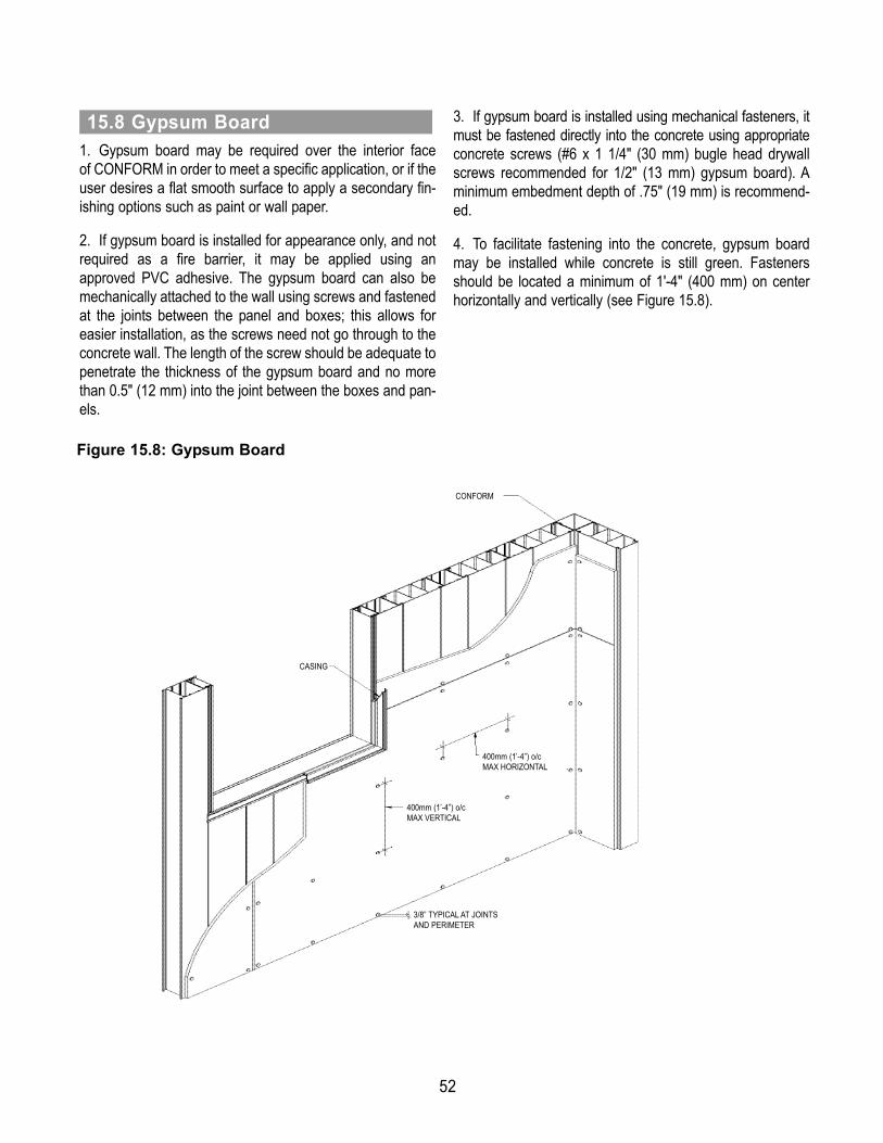
52
1. Gypsum board may be required over the interior face of CONFORM in order to meet a specific application, or if theuser desires a flat smooth surface to apply a secondary fin-ishing options such as paint or wall paper.2. If gypsum board is installed for appearance only, and notrequired as a fire barrier, it may be applied using anapproved PVC adhesive. The gypsum board can also bemechanically attached to the wall using screws and fastenedat the joints between the panel and boxes; this allows foreasier installation, as the screws need not go through to theconcrete wall. The length of the screw should be adequate topenetrate the thickness of the gypsum board and no morethan 0.5" (12 mm) into the joint between the boxes and pan-els.
3. If gypsum board is installed using mechanical fasteners, itmust be fastened directly into the concrete using appropriateconcrete screws (#6 x 1 1/4" (30 mm) bugle head drywallscrews recommended for 1/2" (13 mm) gypsum board). Aminimum embedment depth of .75" (19 mm) is recommend-ed.4. To facilitate fastening into the concrete, gypsum boardmay be installed while concrete is still green. Fastenersshould be located a minimum of 1'-4" (400 mm) on centerhorizontally and vertically (see Figure 15.8).
15.8 Gypsum Board
CASING
CONFORM
400mm (1’-4”) o/cMAX HORIZONTAL
400mm (1’-4”) o/cMAX VERTICAL
3/8” TYPICAL AT JOINTSAND PERIMETER
Figure 15.8: Gypsum Board

53
The following Construction Bulletins provide additional information regarding the construction of walls using CONFORM®. The Construction Bulletins are available on the NUFORM® website www.nuformdirect.com or by contact-ing Nuform Building Technologies Inc. at 1-877-747-9255.
A.1 General
Appendix A: Construction Bulletins
ErectionConstruction Bulletin #1 Building Layout and Foundation DimensionsConstruction Bulletin #2 Sliding of ComponentsConstruction Bulletin #3 Wall Dimensions vs Components ChartConstruction Bulletin #10 Screws (Walls only)Construction Bulletin #11 Construction MaterialsConstruction Bulletin #12 Tools and EquipmentConstruction Bulletin #13 Bracing RequirementsConstruction Bulletin #14 Structural Steel for CF8i WallConstruction Bulletin #15 Starter InstallationConstruction Bulletin #16 Water ResistanceConstruction Bulletin #17 Construction ChecklistsConstruction Bulletin #19 Aluminum Overhead Door Installation
ConcreteConstruction Bulletin #4 Cold Weather RequirementsConstruction Bulletin #6 Hot Weather RequirementsConstruction Bulletin #8 Consolidation of Concrete in CONFORM
FinishingConstruction Bulletin #5 Insulation OptionsConstruction Bulletin #7 Wall Patching ProceduresConstruction Bulletin #9 Hollow Metal Door InstallationConstruction Bulletin #18 Cleaning and MaintenanceConstruction Bulletin #20 CF8i Exterior Face Repair

Appendix B: Bracing for CONFORM®
1. All bracing for CONFORM® must be design by the contractor in accordance with the applicable safety rules and regula-tions, the local building codes and the governing authorities(1). Refer to the Engineering Guide.2. The most effective means of achieving safety in the use of CONFORM is to have competent supervision during erec-tion and placement of concrete. All activities must be designed, supervised and inspected to ensure that the constructionis completed in a safe manner.3. The most frequent cause of bracing failure is an effect that introduces lateral forces or induces displacement in sup-porting members. Inadequate cross bracing and horizontal bracing is one of the factors most frequently involved in bracingfailure. Even when the basic bracing design is soundly conceived the lack of attention to bracing details and small differ-ences in assembly may cause local weakness or overstress that leads to failure of the bracing.4. All bracing for CONFORM must remain in place until the roof connections and/or lateral diaphragms are installed to thepoured concrete walls.5. The use of scaffolding for bracing of CONFORM is not recommended.
B.1 General
FOUNDATION
STRAPPING
CONFORM
STRAPPING
TIE
VERTICAL
BRACE
FORM ALIGNER
DEAD MAN
Fig B1 Typical Bracing Members
(2) The bracing illustrated in this guide provides general suggestions only. The contractor is solely responsible to ensure that all erection and bracing is com-pleted in a safe manner. NUFORMTM does not assume any liability for the erection and bracing.
54

55
V1
H2
4
3±
5±
V1
H1
V1
H1
50° to 60°
WIND
Fig B2 Bracing Force Diagram
1. Bracing for wind loads should be determined by an experienced bracing designer to meet the requirements of the spe-cific project and site conditions.2. Generally, bracing is designed for a 110 km/h (70 mph) wind based on a 5 year mean occurrence and for a load of notless than 0.48 kPa (10 psf).3. The factors of safety recommended for the design of bracing are 1.5 for the members and 2.0 for the connections.4. Typically, braces are placed at an angle between 50º and 60º, i.e. the horizontal dimension is between 75% and 50%of the vertical height.5. Strong-backs, cross-bridging, or knee braces are installed on long braces to ensure that the braces do not buckle underload.6. Deadmen or a foundation slab are required to anchor all braces.7. A form aligner or turnbuckle is recommended at one end of each brace for ease of plumbing and aligning CONFORM.
B.2 Bracing Design Guidelines

56
1. Single bracing consists of strapping at the top and bottom of CONFORM and diagonal braces at 1.8 to 3.0 m (6' to 10')on center, to the top of CONFORM.2. The following figures illustrate single wood bracing with strapping on both sides.
B.3 Single Bracing
WOOD TIE
AT 0.9 TO 1.5m (3' TO 5') o/c
WOOD BRACE
AT 1.8 TO 3.0m (6' TO 10') o/c
CONTINUOUS
WOOD STRAPPING
CONFORM
CONTINUOUS
WOOD STRAPPING STEEL FORM ALIGNER
ANCHORED TO
FOUNDATION
WOOD VERTICAL
AT EACH BRACE
FOR HOLD DOWN
(IF REQUIRED)
B
A
WOOD TIES (3/4" x 2 1/2") PLYWOOD MIN.)
AT 0.9 TO 1.5m (3' TO 5') o/c WITH NAILS
TO WOOD STRAPPING AND WIRED TO
CONFORM WEBS. LOCATE TIES CENTERED
ON CONFORM WEB TO ALLOW CONCRETE
PLACEMENT IN CELL AT EACH SIDE
WOOD BRACE (2 x4 MIN.)
AT 1.8 TO 3.0m (6' TO 10') o/c
NAILED TO WOOD STRAPPING
CONTINUOUS
WOOD STRAPPING (2 x 4 MIN.)
TIGHT TO EACH SIDE
DETAIL A
CONTINUOUS
WOOD STRAPPING (2 x 4 MIN.)
TIGHT TO EACH SIDE AND
ANCHORED TO FOUNDATION WITH
1/4"ø CONCRETE NAILS OR
SCREWS AT 600mm (2'-0") o/c MAX.
DETAIL B
Fig B3-1a Single Wood Bracing with Strapping onBoth Sides - Top Detail
Fig B3-1b Single Wood Bracing with Strappingon Both Sides - Bottom Detail
Fig B3-1 Single Wood Bracing with Strapping on Both Sides

57
3. The following figures illustrate single steel bracing with strapping on both sides.
B
A
STEEL TIE
AT 0.9 TO 1.5m (3' TO 5') o/c
STEEL BRACE
AT 1.8 TO 3.0m (6' TO 10') o/c
CONTINUOUS
STEEL STRAPPING
CONFORM
CONTINUOUS
STEEL STRAPPING
STEEL FORM ALIGNER
ANCHORED TO
FOUNDATION
STEEL HINGE
CONTINUOUS
STEEL STRAPPING
(1 5/8" x 1 5/8" CHANNEL)
TIGHT TO EACH SIDE
#10 HEX HEAD
TEK SCREWS
#10 HEX HEAD
TEK SCREWS
STEEL BRACE
(1 5/8" x 1 5/8" CHANNEL)
AT 1.8 TO 3.0m (6' TO 10') o/c
STEEL HINGE
(6" HEAVY DUTY T-HINGE)
STEEL TIES
(3/16" x 1 1/2" U FITTING)
AT 0.9 TO 1.5m (3' TO 5') o/c
AND WIRED TO CONFORM WEBS
DETAIL A
CONTINUOUS
STEEL STRAPPING (2" x 2" ANGLE MIN.)
TIGHT TO EACH SIDE
#10 SCREWS
AT 1000mm (3'-4") o/c MAX. TO
1/4"ø CONCRETE NAILS OR SCREWS
AT 600mm (2'-0") o/c MAX.
DETAIL B
Fig B3-2a Single Steel Bracing with Strappingon Both Sides - Top Detail
Fig B3-2b Single Steel Bracing with Strappingon Both Sides - Bottom Detail
Fig B3-2 Single Steel Bracing with Strapping on Both Sides
TM

58
4. The following figures illustrate single steel bracing with strapping on one side only.
CONTINUOUS
STEEL STRAPPING
CONTINUOUS
STEEL STRAPPING
STEEL HINGE
STEEL BRACE
AT 1.8 TO 3.0m (6' TO 10') o/cCONFORM
STEEL FORM ALIGNER
ANCHORED TO
FOUNDATIONB
A
CONTINUOUS
STEEL STRAPPING
(1 5/8" x 1 5/8" CHANNEL
OR 2" x 2" ANGLE MIN.)
#10 HEX HEAD
TEK SCREWS
STEEL BRACE
(1 5/8" x 1 5/8" CHANNEL) AT
1.8 TO 3.0m (6' TO 10') o/c
STEEL HINGE
(6" HEAVY DUTY T-HINGE)
#10 SCREWS
AT 400mm (16") o/c MAX.
TO CONFORM
DETAIL A
DETAIL B
CONTINUOUS
STEEL STRAPPING (2" x 2" ANGLE MIN.)
#10 SCREWS
AT 400mm (16") o/c MAX. TO CONFORM
1/4"ø CONCRETE NAILS OR SCREWS
AT 600mm (2'-0") o/c MAX.
Fig B3-3a Single Steel Bracing with Strappingon One Side - Top Detail
Fig B3-3b Single Steel Bracing with Strappingon One Side - Bottom Detail
Fig B3-3 Single Steel Bracing with Strapping on One Side

59
1. Double bracing consists of strapping at the top, bottom and mid-height of CONFORM and diagonal braces at 1.8 to 3.0 m(6' to 10') on center, to the top and mid-height of CONFORM.2. Horizontal strapping and braces are provided near mid-height of CONFORM to maintain the plumb of the walls, to resistconstruction loads during placement of concrete and to resist lateral wind loads. For walls with staggered joints the mid-height bracing is placed along one of the joints.3. Double bracing is required for locations with large wind loads or projects with high walls. Typically, this applies to CF4forms over 4 m (13'), CF6 forms over 5 m (16') and CF8 or CF8i forms over 5.5 m (18').4. The following figures illustrate double wood bracing with strapping on both sides.
B.4 Double Bracing
WOOD TIE
AT 0.9 TO 1.5m (3' TO 5') o/c
WOOD BRACES
AT 1.8 TO 3.0m (6' TO 10') o/c
WITH STRONG BACKS OR
BRIDGING AND KNEE BRACES
(AS REQUIRED)
CONTINUOUS
WOOD STRAPPING
CONFORM
CONTINUOUS
WOOD STRAPPING
CONTINUOUS
WOOD STRAPPING
STEEL FORM ALIGNER
ANCHORED TO FOUNDATION
B
A
WOOD VERTICAL
AT EACH BRACE
FOR HOLD DOWN
C
WOOD TIES (3/4" x 2 1/2") PLYWOOD MIN.)
AT 0.9 TO 1.5m (3' TO 5') o/c WITH NAILS
TO WOOD STRAPPING AND WIRED TO
CONFORM WEBS. LOCATE TIES CENTERED
ON CONFORM WEB TO ALLOW CONCRETE
PLACEMENT IN CELL AT EACH SIDE
WOOD BRACE
AT 1.8 TO 3.0m (6' TO 10') o/c
WITH STRONG BACKS,
BRIDGING OR KNEE BRACES
(AS REQUIRED)
CONTINUOUS
WOOD STRAPPING (2 x4 MIN.)
TIGHT TO EACH SIDE
DETAIL A
DETAIL B
WOOD BRACE (2 x4 MIN.)
AT 1.8 TO 3.0m (6' TO 10') o/c
NAILED TO WOOD STRAPPING
CONTINUOUS
WOOD STRAPPING (2 x4 MIN.)
TIGHT TO EACH SIDE
WOOD VERTICAL (2 x4 MIN.)
AT EACH SIDE ANCHORED TO
WOOD BRACE AND FOUNDATION
CONTINUOUS
WOOD STRAPPING (2 x 4 MIN.)
TIGHT TO EACH SIDE AND
ANCHORED TO FOUNDATION
WITH 1/4"ø CONCRETE NAILS OR
SCREWS AT 400mm (16") o/c MAX.
DETAIL C
WOOD VERTICAL (2 x4 MIN.)
AT EACH SIDE ANCHORED TO
WOOD BRACE AND FOUNDATION
Fig B4-1a Double Wood Bracing with Strappingon Both Sides - Top Detail
Fig B4-1b Double Wood Bracing with Strappingon Both Sides - Mid-Height Detail
Fig B4-1 Double Wood Bracing with Strapping on Both Sides
Fig B4-1c Double Wood Bracing with Strappingon Both Sides - Bottom Detail
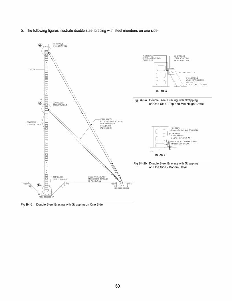
60
5. The following figures illustrate double steel bracing with steel members on one side.
B
A
A
STEEL BRACES
AT 1.8 TO 3.0m (6' TO 10') o/c
WITH BRIDGING OR
KNEE BRACES
(AS REQUIRED)
CONFORM
CONTINUOUS
STEEL STRAPPING
STEEL FORM ALIGNER
ANCHORED TO DEADMAN
OR FOUNDATION
STAGGERED
CONFORM JOINTS
CONTINUOUS
STEEL STRAPPING
SIM
CONTINUOUS
STEEL STRAPPING
CONTINUOUS
STEEL STRAPPING
(3" x 3" ANGLE MIN.)
STEEL BRACING
(ANGLE, PIPE SHORING
OR I SHAPE)
AT 0.9 TO 1.5m (3' TO 5') o/c
BOLTED CONNECTION
DETAIL A
#10 SCREWS
AT 200mm (8") o/c MAX.
TO CONFORM
CONTINUOUS
STEEL STRAPPING
(2 1/2" x 2 1/2" ANGLE MIN.)
DETAIL B
#10 SCREWS
AT 400mm (16") o/c MAX. TO CONFORM
1/4"ø CONCRETE NAILS OR SCREWS
AT 400mm (16") o/c MAX.
Fig B4-2a Double Steel Bracing with Strappingon One Side - Top and Mid-Height Detail
Fig B4-2b Double Steel Bracing with Strappingon One Side - Bottom Detail
Fig B4-2 Double Steel Bracing with Strapping on One Side

61
6. The following figures illustrate double cable bracing with strapping on both sides.
B
A
A
WIRE CABLES
AT 1.8 TO 3.0m (6' TO 10') o/c
CONFORM
CONTINUOUS
WOOD STRAPPING
TURN BUCKLES
ANCHORED TO
DEADMAN OR
FOUNDATION
STAGGERED
CONFORM JOINTS
CONTINUOUS
STEEL STRAPPING
CONTINUOUS
STEEL STRAPPING
SIM
CONTINUOUS
STEEL STRAPPING
(3" x 3" ANGLE MIN.)
TIGHT TO EACH SIDE
WIRE CABLES
AT 1.8 TO 3.0m (6' TO 10') o/c
DETAIL A
CABLE BOLTS
AT 1.8 TO 3.0m (6' TO 10') o/c
CONTINUOUS
WOOD STRAPPING (2 x 4 MIN.)
TIGHT TO EACH SIDE AND ANCHORED
TO FOUNDATION WITH 1/4"ø
CONCRETE NAILS OR SCREWS AT
600mm (2'-0") o/c MAX.
DETAIL B
Fig B4-3a Double Cable Bracing with Strappingon Both Sides - Top and Mid-Height Detail
Fig B4-3b Double Cable Bracing with Strappingon Both Sides - Bottom Detail
Fig B4-3 Double Cable Bracing with Strapping on Both Sides

62
1. When the concrete is poured into the cells of the CONFORM components, it flows a maximum of 1.2 m (4') laterally fromthe cell in which it is placed and hydrostatic pressures are exerted on the webs of the cells. The resulting forces in the planeof the wall must be resisted by vertical and diagonal bracing at corners, intersections and ends of walls in order to main-tain CONFORM square and plumb. The vertical bracing is connected to the foundation and is laterally supported with diag-onal bracing at the top and at 1.5 to 2 m (5' to 7') on center.2. Vertical bracing with diagonal braces is placed both ways at corners of walls. This is to prevent bowing of the form face,to hold the face of CONFORM plumb and to prevent expansion or shifting of CONFORM during placement of concrete.
B.5 Vertical Bracing at Corners, T-Intersections and Ends
MID HEIGHT
WOOD BRACE
OPTIONAL FOR HEIGHTS
LESS THAN 3m (10')
ANCHOR
VERTICAL BRACING
TO FOUNDATION
WITH BLOCKING
WOOD BRACE WITH
STRONG BACK OR
BRIDGING AND KNEE
BRACES (AS REQUIRED)
VERTICAL WOOD FORM
(2" NOMINAL LUMBER)
TIGHT TO CORNER BOX
(OPTIONAL FOR CF4
CORNER BOXES AND FOR
CF8i EXTERIOR CORNER
BOXES AT TOP 3m (10')
OF WALL)
Fig B5-1 Vertical Corner Bracing
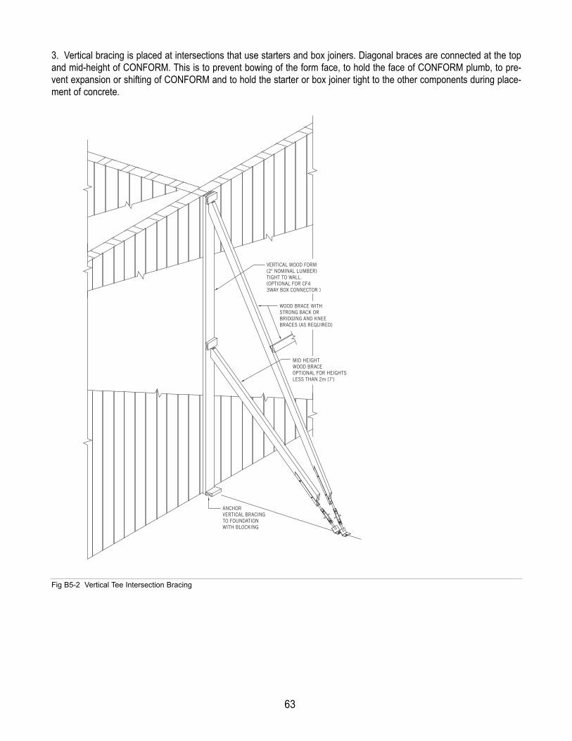
63
MID HEIGHT
WOOD BRACE
OPTIONAL FOR HEIGHTS
LESS THAN 2m (7')
ANCHOR
VERTICAL BRACING
TO FOUNDATION
WITH BLOCKING
WOOD BRACE WITH
STRONG BACK OR
BRIDGING AND KNEE
BRACES (AS REQUIRED)
VERTICAL WOOD FORM
(2" NOMINAL LUMBER)
TIGHT TO WALL.
(OPTIONAL FOR CF4
3WAY BOX CONNECTOR )
3. Vertical bracing is placed at intersections that use starters and box joiners. Diagonal braces are connected at the topand mid-height of CONFORM. This is to prevent bowing of the form face, to hold the face of CONFORM plumb, to pre-vent expansion or shifting of CONFORM and to hold the starter or box joiner tight to the other components during place-ment of concrete.
Fig B5-2 Vertical Tee Intersection Bracing
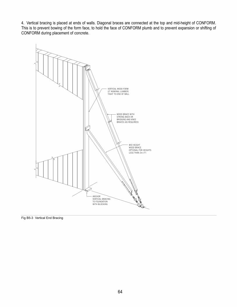
64
MID HEIGHT
WOOD BRACE
OPTIONAL FOR HEIGHTS
LESS THAN 2m (7')
ANCHOR
VERTICAL BRACING
TO FOUNDATION
WITH BLOCKING
WOOD BRACE WITH
STRONG BACK OR
BRIDGING AND KNEE
BRACES (AS REQUIRED)
VERTICAL WOOD FORM
(2" NOMINAL LUMBER)
TIGHT TO END OF WALL
4. Vertical bracing is placed at ends of walls. Diagonal braces are connected at the top and mid-height of CONFORM.This is to prevent bowing of the form face, to hold the face of CONFORM plumb and to prevent expansion or shifting ofCONFORM during placement of concrete.
Fig B5-3 Vertical End Bracing

65
1. Bracing is required at openings to keep the opening square, to prevent bowing of jambs and to contain and support thewet concrete in the header during concrete placement. 2. For large openings, diagonal bracing is required at the top and bottom of the headers to hold the header straight andplump and to hold the header flush with the wall at each end of the header.3. For openings adjacent to corners and piers between openings the horizontal bracing for the jambs can be achieved byclamping.
B.6 Bracing at Openings
BOTTOM BRACE AT
40mm (1 1/2") CLEAR
FOR DRAINAGE
DURING CLEANING
CONFORM
PLYWOOD GUSSETS TO
MAINTAIN SQUARE
OPENING (OPTIONAL)
WOOD BRACING
CLAMPED TO EACH SIDE
TO MAINTAIN PLUMB AND
ALIGNMENT OF HEADER,
(LATERAL BRACING
REQUIRED FOR LARGE
OPENINGS)
WOOD BRACING TIGHT
TO UNDERSIDE OF HEADER
WITH VERTICAL BRACING
AT EACH END
AND 700mm (2'-4") o/c MAX.
(MAINTAIN SPECIFIED
OPENING HEIGHT)
WOOD BRACING TIGHT
TO EACH JAMB WITH
HORIZONTAL BRACING
AT 900mm (3'-0") o/c MAX.
(MAINTAIN SPECIFIED
OPENING WIDTH)
Fig B6-1 Door Bracing

66
WOOD BRACING TIGHT
TO UNDERSIDE OF HEADER
WITH VERTICAL BRACING
AT EACH END
AND 700mm (2'-4") o/c MAX.
(MAINTAIN SPECIFIED
OPENING HEIGHT)
WOOD BRACING TIGHT
TO EACH JAMB WITH
HORIZONTAL BRACING
AT 900mm (3'-0") o/c MAX.
(MAINTAIN SPECIFIED
OPENING WIDTH)
CONFORM
PLYWOOD GUSSETS
TO MAINTAIN SQUARE
OPENING (OPTIONAL)
WOOD BRACING TIGHT
TO EACH JAMB AFTER
SILLS ARE POURED
WITH CONCRETE
WOOD BRACING
CLAMPED TO EACH SIDE
TO MAINTAIN PLUMB AND
ALIGNMENT OF HEADER,
(LATERAL BRACING
REQUIRED FOR LARGE
OPENINGS)
WOOD BLOCKS
ANCHORED TO SILL
UNDER VERTICAL
BRACES (POUR
CONCRETE FROM
TOP OF SILL)
Fig B6-2 Window Bracing
VERTICAL BRACING
BRACING AT
900mm (3'-0") o/c MAX.
CONFORM STARTER CONFORM BOX
1/2" PLYWOOD, SHIMS
AND VERTICAL BRACING
SCREWS AT 600mm (2'-0") o/c
VERTICAL BLOCKING
AND BRACING
STEEL WRAP
AROUND FRAME
BRACING AT
900mm (3'-0") o/c MAX.
BRACING AT
900mm (3'-0") o/c MAX.
Fig B6-3 Opening Details

67
Fig B7-2 Column and Double Wall Bracing
Fig B7-1 Pilaster Bracing
1. Additional bracing is required at pilasters that are created using CONFORM components. The concrete pressure isexerted at the outmost faces and will create tension through all interconnecting pieces. During concrete placement, startersmay pull away from an adjoining wall and box joiners may not be adequate to hold two box connectors together. Additionalbracing is provided to resist the tension that is created and hold the CONFORM components straight and plumb.
B.7 Bracing at Piers, Columns and Double Walls
FULL HEIGHT VERTICAL
BRACING TO HOLD
STARTERS TIGHT TO
WALL COMPONENTS
JOINT TO BE
HELD TIGHT
JOINT TO BE
HELD TIGHT
STARTER
FULL HEIGHT
BRACING TO HOLD
BOX CONNECTORS
TIGHT AT BOX JOINER
HYDROSTATIC PRESSURE
OF WET CONCRETE
BOX JOINER
HYDROSTATIC PRESSURE
OF WET CONCRETE
SURFACE OF CONFORM
COMPONENTS TO BE FORMED
FULL HEIGHT FORMWORK AND
BRACING TIGHT TO CONFORM
2. Additional bracing is required at columns and double walls where concrete is placed between two layers of CONFORM.An entire CONFORM panel or section of wall may bow when concrete is placed between two layers of CONFORM.Bracing is provided to resist the hydrostatic pressures of the wet concrete between the two walls and to hold the entireCONFORM straight and plumb during concrete placement. Alternately, concrete is placed in the CONFORM componentsonly and allowed to set prior to placing concrete between the two layers of CONFORM.
TM

68
28'-11"
19'-0" 8'-5"6" 6" 6"
CAR WASH
ELECTRICAL
ROOM
STORAGE
ROOM
6"
6"
6"
37'-10"
21'-4"
15'-0"
A A
12'-6"
1'-6"
PLAN
SECTION A-A
Fig B8-1 Project Layout
1. This example illustrates the bracing layout for a simple project • Car Wash Building - 28'-11" x 37'-10".• Wall height - 14'-0" (12'-6" above grade and 1'-6" below grade).• Concrete walls using CF6 forms - 6" thick, as specified to meet structural requirements.• Finished wall surface is CONFORM exposed full height on both sides.
B.8 Bracing Example

69
3/4" x 1 1/2" WIDE PLYWOOD TIE
AT 3'-4" o/c MAX.
2 x 4 WOOD BRACE
AT 8'-0" o/c MAX.
CONTINUOUS TOP
2 x 4 WOOD STRAPPING
CONFORM
CONTINUOUS BOTTOM
2 x 4 WOOD STRAPPING STEEL FORM ALIGNER
ANCHORED TO DEAD MAN
2 x 4 WOOD VERTICAL
AT EACH BRACE
FOR HOLD DOWN
(IF REQUIRED)
14'-0"
60°
FINISH FLOOR
6" 7'-9" ±
2. Select Erection Method (Refer to Section 2.3 of this guide)• Erection using individual components is selected due to small size of structure, 14' wall height, site conditions and
available equipment. • Starting corner is selected due to site conditions and contractor’s preference.
3. Select Bracing Method (Refer to Section B.3 of this guide)• Single bracing is selected due to 14' wall height.• Wood bracing is selected due to available materials• Strapping on both sides is selected since CONFORM will be the exposed finished wall surface.
Fig B8-2 Bracing Section
TM
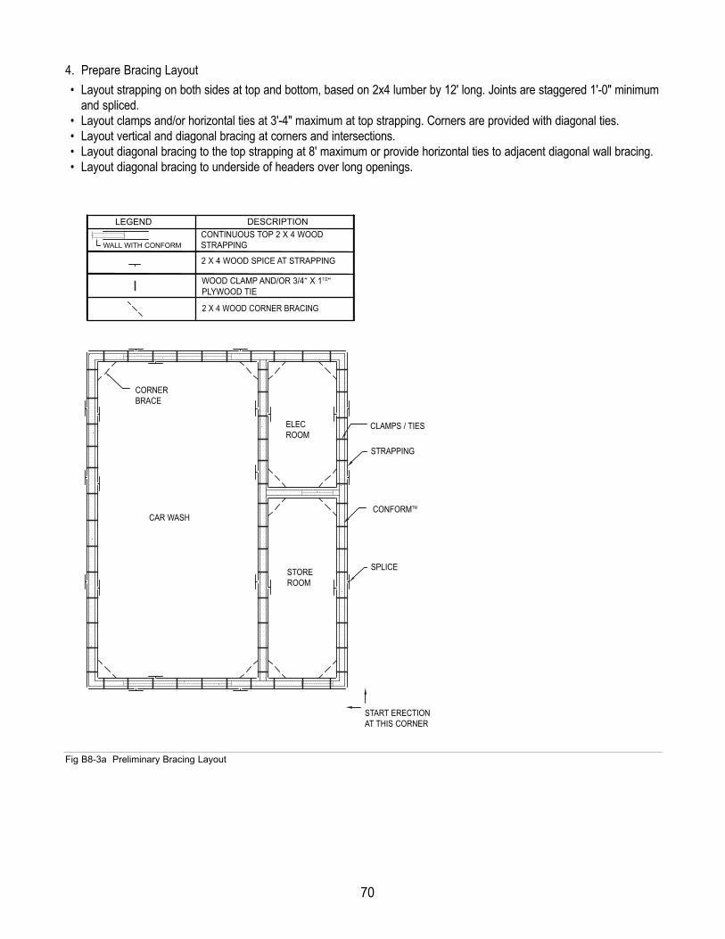
70
LEGEND DESCRIPTION
CAR WASH
STORE
ROOM
ELEC
ROOM
START ERECTION
AT THIS CORNER
CORNER
BRACE
WAL L WITH CONFORM
CONTINUOUS TOP 2 x 4 WOOD
STRAPPING
2 x 4 WOOD SPLICE AT STRAPPING
2 x 4 WOOD CORNER BRACING
WOOD CLAMP AND/OR 3/4" x 1
1/2" PLYWOOD TIE
CONFORM
SPLICE
CLAMPS / TIES
STRAPPING
4. Prepare Bracing Layout • Layout strapping on both sides at top and bottom, based on 2x4 lumber by 12' long. Joints are staggered 1'-0" minimum
and spliced.• Layout clamps and/or horizontal ties at 3'-4" maximum at top strapping. Corners are provided with diagonal ties.• Layout vertical and diagonal bracing at corners and intersections.• Layout diagonal bracing to the top strapping at 8' maximum or provide horizontal ties to adjacent diagonal wall bracing.• Layout diagonal bracing to underside of headers over long openings.
Fig B8-3a Preliminary Bracing Layout
CONTINUOUS TOP 2 X 4 WOODSTRAPPING
DESCRIPTIONLEGEND
2 X 4 WOOD SPICE AT STRAPPINGWOOD CLAMP AND/OR 3/4” X 11/2”PLYWOOD TIE2 X 4 WOOD CORNER BRACING
WALL WITH CONFORM
CORNERBRACE
ELECROOM
STOREROOM
CAR WASH
CLAMPS / TIES
STRAPPING
CONFORMTM
SPLICE
START ERECTIONAT THIS CORNER

71
5. Verify Bracing Layout and Member Sizes based on Engineering Analysis of Bracing Requirements• Calculate design loads for bracing based on local climatic conditions and requirements of regulatory authorities.• Verify the load capacity for all bracing members based on assumed member sizes and spacing. Revise member sizes
and spacing as required.
• Determine the connections required between bracing members and determine the anchorage or deadmen required for the diagonal braces.
• Determine the bracing for openings based on the weight and hydrostatic pressure of the wet concrete.
LEGEND
HORIZ
HEADER
DESCRIPTION
2 x 6 WOOD VERTICAL & DIAGONAL 2 x 4 WOOD BRACE AT CORNERS AND INTERSECTIONS
DIAGONAL 2 x 4 WOOD BRACE TO TOP WALLS AT 8'-0" o/c MAX.
DIAGONAL 2 x 4 WOOD BRACE TO UNDERSIDE HEADER AT 8'-0" MAX.
HORIZONTAL 2 x 4 WOOD BRACE AT 8'-0" o/c MAX.
HE
AD
ER
HE
AD
ER
CAR WASH
HORIZ
HORIZ
HORIZ
FIG B6-1
STORE ROOM
ELEC ROOM
HE
AD
ER
HE
AD
ER
FIG B8-2
FIG B5-1
FIG B5-2
START ERECTION AT THIS CORNER
VERTICAL & DIAGONAL BRACE
DIAGONAL BRACE
Fig B8-3b Preliminary Bracing Layout

Notes

We hope you found this guide informative while designing your project using CONFORM®.As always, our main goal at Nuform BuildingTechnologies Inc. is to ensure that our valued customers are 100% satisfied with our service andwith CONFORM. Should you have any questions orcomments, we would like to hear from you. You maycontact us at the following:Please visit the Technical Section of our web site atwww.nuformdirect.com for the latest version of thisguide. Please forward us any suggestions or com-ments for improving this guide. All suggestions forimprovements will be given full consideration forfuture revisions.
PURCHASER IS SOLELY RESPONSIBLE FOR DETERMINING THE SUITABIL-ITY FOR USE OR APPLICATION OF ANY GOODS, INCLUDING COMPONENTSTHEREOF, OR WHETHER SUCH GOODS MEET REQUIREMENTS OF APPLI-CABLE BUILDING CODES OR SAFETY CODES FOR SPECIFIC APPLICA-TIONS.
© 2012 Nuform Building Technologies Inc. All rights reserved. Reasonableefforts have been made to ensure the accuracy of this publication; howev-er, any information and data contained herein is subject to change withoutnotice.

For more photos and information, visit our Web site atwww.nuformdi rec t .com
Nuform Building Technologies Inc.100 Galcat Drive, Unit #2Woodbridge, Ontario, CanadaL4L 0B9
Toll Free: 1 877-747-WALL (9255)Tel.: 905-652-0001Fax: 905-652-0002
PURCHASER IS SOLELY RESPON-SIBLE FOR DETERMINING THESUITABILITY FOR USE OR APPLI-CATION OF ANY GOODS, INCLUD-ING COMPONENTSTHEREOF, OR WHETHER SUCHGOODS MEET REQUIREMENTS OFAPPLICABLE BUILDING CODES ORSAFETY CODES FOR SPECIFICAPPLICATIONS.
The Pre-F in ished, Stay- in-PlaceConcrete Wal l Formwork
NUFORM, CONFORM, RELINE and the “N” logo are registered trademarks of Nuform Building Technologies Inc.