15100 Mechanical Systems Design Criteria 05-13-15facilities.mysdhc.org/PandC/standards/15100...
34
Mechanical Criteria 1/29 MECHANICAL SYSTEMS DESIGN CRITERIA DOCUMENT NUMBER: 15100 APPLICATION: ELEMENTARY, MIDDLE AND HIGH SCHOOL DATE OF ISSUE: 05-13-15 - Revised paragraph C.5 and C.6 related to ventilation criteria 04-24-15 - Miscellaneous revisions 02-03-15 - Revised criteria in Section A for chiller design temperature difference. 01-23-15 - Revised criteria in Section A for chillers/piping; deleted primary/secondary configuration from Figure 05. 04-21-14 - Added Note B.27 – Central Station Air Handlers 07-23-13 - Added Note E.11, prohibiting relief dampers 04-25-13 - Added Figure 08a – Kiln Wiring Schematic Diagram 06-15-11 - Revised & reformatted entire document, organized into the following sections: A. Chillers / Piping B. Equipment Placement and Serviceability C. Design Data D. Duct Design E. Ventilation Systems F. Controls Systems G. Cooling Systems for New Schools and Renovations H. DX Equipment I. Cooling Towers J. Training 04-02-10 - revised chiller plant equipment criteria 10-05-09 - revised chiller piping configuration and table for outdoor air ventilation rates 05-01-08 - simplified ventilation design criteria & added criteria for sizing chilled water pipe & thermostat For older revisions, refer to previous versions of this document NOTES: 1. The project engineer hereby acknowledges the requirements of this Standard by submitting a signed and sealed copy of this document with the Schematic (Phase 1) submittal. 2. Submit APPROVED HVAC equipment submittals as part of the close out documents. Review the SDHC Close Out Document Standard for more information. Approved submittals are to be provided in PDF format on CD-ROM. Note: this is a close out document requirement for the Design Professional, not the GC / CM. 3. Any deviations from this Standard require written approval by the District’s engineer, prior to construction. ____________________________________________ School / Project Name ____________________________________________ ____________________________ Mechanical Engineer of Record Date ATTACHMENTS: Extended Warranty Format, dated 04-24-15 Preventative Maintenance Agreement Format, dated 04-24-15 FIGURES REFERENCED HEREIN: Figure 01 Cooling Tower Piping Diagram Figure 02 Ice Storage Schematic – Nighttime Operation Figure 03 Ice Storage Schematic – Daytime Operation Figure 04 Pump Detail Figure 05 Vari-prime Pumping Diagram Figure 06 Piping Connections (No Bull-Heading) Figure 07 Kitchen Ventilation / Tempering Systems Figure 08 Kiln Room Ventilation Systems Figure 08a Kiln Room Wiring Schematic Diagram Figure 09 Outside Make-up Air Control Diagram Figure 10 Gym Ventilation With & Without Locker Rooms Figure 11 Gym Duct Layout (Single Duct Design) Figure 12 Gym Duct Layout (Twin Duct Design) Figure 13 Standard Pump Schedule Figure 14 Standard Variable Frequency Drive Schedule Figure 15 Standard Heat Exchanger Schedule Figure 16 Standard Air Handler Schedule Figure 17 Standard Air Cooled Chiller Schedule Figure 18 Standard Ice Storage Tank Schedule
Transcript of 15100 Mechanical Systems Design Criteria 05-13-15facilities.mysdhc.org/PandC/standards/15100...

Mechanical Criteria 1/29
MECHANICAL SYSTEMS DESIGN CRITERIA DOCUMENT NUMBER: 15100 APPLICATION: ELEMENTARY, MIDDLE AND HIGH SCHOOL DATE OF ISSUE: 05-13-15 - Revised paragraph C.5 and C.6 related to ventilation criteria 04-24-15 - Miscellaneous revisions 02-03-15 - Revised criteria in Section A for chiller design temperature difference. 01-23-15 - Revised criteria in Section A for chillers/piping; deleted primary/secondary configuration
from Figure 05. 04-21-14 - Added Note B.27 – Central Station Air Handlers 07-23-13 - Added Note E.11, prohibiting relief dampers 04-25-13 - Added Figure 08a – Kiln Wiring Schematic Diagram 06-15-11 - Revised & reformatted entire document, organized into the following sections: A. Chillers / Piping
B. Equipment Placement and Serviceability C. Design Data D. Duct Design E. Ventilation Systems
F. Controls Systems G. Cooling Systems for New Schools and Renovations H. DX Equipment I. Cooling Towers J. Training
04-02-10 - revised chiller plant equipment criteria 10-05-09 - revised chiller piping configuration and table for outdoor air ventilation rates 05-01-08 - simplified ventilation design criteria & added criteria for sizing chilled water pipe & thermostat For older revisions, refer to previous versions of this document NOTES: 1. The project engineer hereby acknowledges the requirements of this Standard by submitting a signed and
sealed copy of this document with the Schematic (Phase 1) submittal. 2. Submit APPROVED HVAC equipment submittals as part of the close out documents. Review the SDHC
Close Out Document Standard for more information. Approved submittals are to be provided in PDF format on CD-ROM. Note: this is a close out document requirement for the Design Professional, not the GC / CM.
3. Any deviations from this Standard require written approval by the District’s engineer, prior to
construction. ____________________________________________ School / Project Name ____________________________________________ ____________________________ Mechanical Engineer of Record Date ATTACHMENTS: Extended Warranty Format, dated 04-24-15 Preventative Maintenance Agreement Format, dated 04-24-15 FIGURES REFERENCED HEREIN: Figure 01 Cooling Tower Piping Diagram Figure 02 Ice Storage Schematic – Nighttime Operation Figure 03 Ice Storage Schematic – Daytime Operation Figure 04 Pump Detail Figure 05 Vari-prime Pumping Diagram Figure 06 Piping Connections (No Bull-Heading) Figure 07 Kitchen Ventilation / Tempering Systems Figure 08 Kiln Room Ventilation Systems Figure 08a Kiln Room Wiring Schematic Diagram Figure 09 Outside Make-up Air Control Diagram
Figure 10 Gym Ventilation With & Without Locker Rooms Figure 11 Gym Duct Layout (Single Duct Design) Figure 12 Gym Duct Layout (Twin Duct Design) Figure 13 Standard Pump Schedule Figure 14 Standard Variable Frequency Drive Schedule Figure 15 Standard Heat Exchanger Schedule Figure 16 Standard Air Handler Schedule Figure 17 Standard Air Cooled Chiller Schedule Figure 18 Standard Ice Storage Tank Schedule

Mechanical Criteria 2/29
A. Chillers / Piping 1. Instead of one large chiller, use two half sized chillers. Total chiller capacity to equal the School’s block
cooling load. Engineer to submit a copy of the School’s block load calculation at Design Development submittal phase.
2. Chillers to be piped in parallel, not in series. 3. Each chiller shall be served by its own dedicated pump. For operational flexibility, provide a discharge
manifold with manual valves to allow a pump to serve the other chiller, and also able to allow a pump to serve both chillers in a parallel pumping configuration.
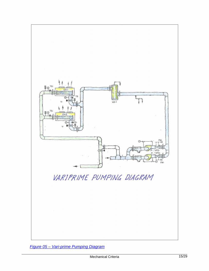
4. Do not provide chilled and condenser water stand-by pumps. 5. Chiller design leaving water temperature shall be 42° F. 6. Chiller design temperature difference shall be a minimum of 12° F and a maximum of 15° F. 7. The maximum water flow pressure drop through chilled water pipe to be 4.0 ft/ 100ft. 8. Chilled water pumping can be either of the following (Figure 05): a. Vari-prime using VF drives to control variable flow. b. Constant volume pumping with 3-way valves on small CHW applications. 9. Air cooled chillers up to 140 tons: Compressors shall be scroll type. 10. Air cooled chillers greater than 140 tons: Compressors shall be helical/ screw or scroll type. 11. Selection of the chillers shall be based on a 15 year life cycle on air-cooled equipment and 25-years on
water-cooled, based on first cost, warranty cost, and energy cost 12. Chiller warranty and Preventative Maintenance Agreement to be specified as follows:
a. Warranty:
As base bid, require the manufacturer’s standard 1 year warranty, plus additional years 2-10 labor and material warranty in the format provided in this document.
b. Preventative Maintenance Agreement:
1) Require 2 separate ADD ALTERNATES, as follows:
Alternate 1: provide an alternate price for all preventive maintenance services listed in the sample agreement provided herein, for a period commencing on the date of start-up and ending five years from the date of start-up. Alternate 2: provide an alternate price for all preventive maintenance services listed in the sample agreement provided herein, for a period commencing upon expiration of the services described in Alternate 1, and ending ten years from the date of start-up.
2) If awarded, the Owner will issue a separate purchase order each year that the Preventative Maintenance Agreement is extended.
3) Payments for services provided under this Agreement become due upon the completion of each
service call and associated reporting. Where multiple service visits are scheduled in a year, amounts attributable to each service call will be pro-rated according to the number of services scheduled.

Mechanical Criteria 3/29
4) If awarded, the contractor is required to execute and submit the Preventative Maintenance Agreement to the HCPS Maintenance Department within 4 weeks of equipment start-up.
Failure to submit the Agreement timely, and/or failure to schedule and perform the tasks listed in the sample Agreement included herein does not relieve the Vendor of the responsibility for proper maintenance of the equipment provided under this contract.
5) Service calls are to be scheduled with the HCPS Maintenance Department a minimum of 2
weeks in advance of the scheduled date.
6) Each service call is to result in a written report, to include the logs and calculations required below, and a checklist in the below-listed format as well as recommendations for corrective actions. The report shall be forwarded via e-mail within seven (7) days of the service call to Mr. PJ Crespo, Manager of the HVAC and Energy Management Department ([email protected] ). Invoices will not be processed for services which are not documented with a written report.
12. Specify a minimum of two separate refrigerant circuits per chiller. 13. The use of a non-adjustable, chilled water Flow Control/ Spring Loaded Valve, is prohibited. 14. Chiller yard:
a. The chiller yard shall be a concrete surface. Outdoor fenced enclosure shall be provided for security of mechanical equipment, fence is to be set a minimum of 6” inside the edge of the concrete. Minimum dimensions to meet chiller manufacturer recommended clearances.
b. Locate mechanical equipment yard in area with good air circulation and away from areas which produce air borne debris (i.e. trash receptacles, dumpsters).
c. Provide adequate lighting located in appropriate areas for service after hours.
d. Provide GFCI protected 120 Volt, 20 amp. outdoor receptacle for service.
e. Provide hose bibb for service. 15. Locate all electrical devices for mechanical equipment and control panels/devices in mechanical
rooms. Disconnects are to be located on the chillers. 16. Provide a 6' high security fence at the chiller yard.
B. Equipment Placement and Serviceability 1. All floor mounted equipment (and equipment on grade) shall be provided with a 6” minimum concrete
pad. 2. The concrete pad is to have no contact with any metal portion of the equipment or that
equipment’s support. Provide ¼” thick red, or black, rubber pad under the entire metal surface intended to rest on the concrete pad.
3. All HVAC equipment (except small fans) shall be floor mounted; not above the ceiling. 4. All chilled water pipe (not including factory manufactured pre-insulated pipe) shall be schedule 40 black
steel, painted with two coats of rust inhibiting paint. 5. Indicate on the mechanical drawings the location all ceiling access panels & wall access panels. The
minimum size is to be 24” x 24”.

Mechanical Criteria 4/29
6. Locate all back-flow preventers serving chilled water systems and domestic water systems, where access and maintenance is convenient without a ladder.
7. Specify the requirement for dielectric unions/ protection at all points of connect between dissimilar
metals; pipe, hangers, connections to structural steel, etc. in the HVAC and Plumbing notes. 8. Specify that all air conditioning filters are to be furnished and changed by the contractor up to the
substantial completion acceptance. From that time on, the District will assume responsibility. 9. Specify that all air conditioning fan belts to be furnished and changed by the contractor up to the
end of the warranty period. From that time on, the District will assume all responsibility. 10. When using small, air cooled mini-split systems (Kitchen Manager’s Office, Dry Storage Room, Data
Rooms, and the like), the location of the condensing unit is to be outside, either pad mounted and enclosed by security fencing, OR wall mounted, as directed for the specific project. When units are wall mounted, the bottom of the bracket to be approximately 9 ft above grade.
11. Placement of VAV Boxes:
a. Locate below bottom chord of trusses or joists, unless Owner grants a special exception in writing.
b. Locate 24” clear (min.) from any lay-in light fixture. 12. No air handler or mechanical room is to be used as a plenum. Provide 24” minimum clearance all
around air handlers, including non-access sides. Provide a hose bibb, floor drain, and 115 Volt, 30 amp receptacle for service in each air handler room. Locate floor drains so that they will be accessible for maintenance after the mechanical equipment is installed.
13. Filter specifications for air handling equipment greater than 60,000 BTUH is to be provided with
2” pleated filters maximum face velocity 300 FPM minimum efficiency, 30% and standard filter manufactured sizes. Filter recommendations for air handling equipment less than 60,000 BTUH must be submitted to the owner for approval.
14. Provide hinged access panels in supply and return at all air handlers to facilitate cleaning of coils
and air handlers. Provide proper clearance for cleaning and service. All air handler sections shall have factory installed access panels to access any area of air handler. All field installed duct plenums shall have field installed access panels. All panels shall be latched by means of bulkhead type latches. Air handler shall be of double wall construction and frame and panels shall be galvanized.
15. Condensate drain pan shall be of stainless steel construction and IAQ ready. It shall have the smallest
surface area necessary. Drain stub out fitting to be of stainless steel. Drain line fitting shall be in the bottom of the condensate pan to completely drain the pan. Condensate drain shall be of schedule 40 PVC, provided with clean-out at P-traps. Route condensate line to nearest floor or roof drain.
16. Condensate drain piping size and routing shall be shown on the documents. Condensate shall be
routed to outside stormwater collection system or dry well, not to the sanitary drain system nor by the use of a “slinger”. NOTE: the District adds no chemical (algaecide, chlorine, and the like) to any air conditioning condensate waste water. Therefore, it is acceptable to discharge condensate in the storm water collection system or to a grassy area outdoors.
17. Cooling coil supports shall be stainless steel. Tube sheets shall be of stainless steel. Coil shall be 10 fin
per inch maximum. Coil shall have access on both sides for cleaning. Where hot water coils or heat strips are installed in air handler, provide sufficient space as not to obstruct one coil with another for cleaning. Provide space for coils to be pulled out horizontally for cleaning.
18. All fan bearings shall have grease fittings (no remote grease lines).
Mechanical Criteria 5/29
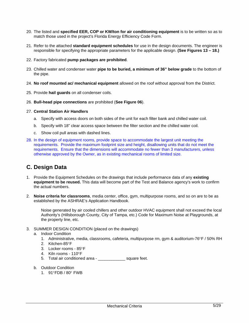
20. The listed and specified EER, COP or KW/ton for air conditioning equipment is to be written so as to match those used in the project’s Florida Energy Efficiency Code Form.
21. Refer to the attached standard equipment schedules for use in the design documents. The engineer is
responsible for specifying the appropriate parameters for the applicable design. (See Figures 13 – 18.) 22. Factory fabricated pump packages are prohibited. 23. Chilled water and condenser water pipe to be buried, a minimum of 36” below grade to the bottom of
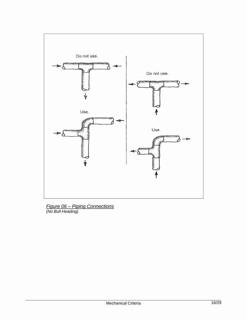
the pipe. 24. No roof mounted ac/ mechanical equipment allowed on the roof without approval from the District. 25. Provide hail guards on all condenser coils. 26. Bull-head pipe connections are prohibited (See Figure 06). 27. Central Station Air Handlers
a. Specify with access doors on both sides of the unit for each filter bank and chilled water coil.
b. Specify with 18” clear access space between the filter section and the chilled water coil.
c. Show coil pull areas with dashed lines.
28. In the design of equipment rooms, provide space to accommodate the largest unit meeting the requirements. Provide the maximum footprint size and height, disallowing units that do not meet the requirements. Ensure that the dimensions will accommodate no fewer than 3 manufacturers, unless otherwise approved by the Owner, as in existing mechanical rooms of limited size.
C. Design Data 1. Provide the Equipment Schedules on the drawings that include performance data of any existing
equipment to be reused. This data will become part of the Test and Balance agency's work to confirm the actual numbers.
2. Noise criteria for classrooms, media center, office, gym, multipurpose rooms, and so on are to be as
established by the ASHRAE’s Application Handbook.
Noise generated by air cooled chillers and other outdoor HVAC equipment shall not exceed the local Authority’s (Hillsborough County, City of Tampa, etc.) Code for Maximum Noise at Playgrounds, at the property line, etc.
3. SUMMER DESIGN CONDITION (placed on the drawings)
a. Indoor Condition 1. Administrative, media, classrooms, cafeteria, multipurpose rm, gym & auditorium-76F / 50% RH 2. Kitchen-85F 3. Locker rooms - 85F 4. Kiln rooms - 110F 5. Total air conditioned area - ____________ square feet. b. Outdoor Condition 1. 91FDB / 80 FWB

Mechanical Criteria 6/29
4. WINTER DESIGN CONDITION (placed on the drawings) a. Indoor Condition 1. Administrative, media, classrooms, cafeteria, multipurpose room, gym & auditorium - 70FDB. b. Outdoor Condition 1. 39 FDB 5. Fresh air ventilation criteria:
As permitted by the intermittent occupancy provisions for school buildings in the FBC, the number of occupants in any calculation of ventilation requirements shall be adjusted by the factors in the table below. The minimum required ventilation shall be not less than 7.5 cfm per peak number of occupants. Note: for projects where adherence to green building criteria is required by code, adjust outside air as required to meet the requirement.
6. For design occupancies, refer to the following: a. High School Prototype Educational Specifications, the “Schedule of Spaces”. b. Middle School Prototype Education Specifications, the “Schedule of Spaces” c. Elementary School Prototype Educational Specifications, the “Schedule of Spaces”.
Classroom I 5.25 ÷ 10.50 = 0.50
Student Schedule: 8:00AM – 2:15PM Cafeteria C 3.50 ÷ 10.50 = 0.33 (use 1.00) (3), (4)
A/C Schedule: 6:00AM – 4:30PM Multipurpose I 5.00 ÷ 10.50 = 0.48 (use 0.50)
Music I 3.50 ÷ 10.50 = 0.33 (use 0.50)
Media Center I 3.50 ÷ 10.50 = 0.33 (use 0.50)
Administration C 6.75 ÷ 10.50 = 0.64 (use 1.00) (3)
Classroom I 4.75 ÷ 10.50 = 0.45 (use 0.50)
Student Schedule: 9:00AM – 3:45PM Cafeteria C 3.50 ÷ 10.50 = 0.33 (use 1.00) (3), (4)
A/C Schedule: 6:00AM – 4:30PM Multipurpose I 4.75 ÷ 10.50 = 0.45 (use 0.50)
Music I 4.00 ÷ 10.50 = 0.38 (use 0.50)
Media Center I 4.00 ÷ 10.50 = 0.38 (use 0.50)
Administration C 6.75 ÷ 10.50 = 0.64 (use 1.00) (3)
Gymnasium I 3.00 ÷ 10.50 = 0.50
Classroom I 6.25 ÷ 10.50 = 0.60
Student Schedule: 7:30AM – 2:50PM Cafeteria C 3.50 ÷ 10.50 = 0.33 (use 1.00) (3), (4)
A/C Schedule: 6:00AM – 4:30PM Auditorium I 4.50 ÷ 10.50 = 0.43 (use 0.50)
Music I 5.00 ÷ 10.50 = 0.48 (use 0.50)
Media Center I 5.00 ÷ 10.50 = 0.48 (use 0.50)
Administration C 6.75 ÷ 10.50 = 0.64 (use 1.00) (3)
Gymnasium I 3.00 ÷ 10.50 = 0.29 (use 0.50)
(1)
(2)
(3)
(4)
Type (1)
UTILIZATIONFACILITY
÷ =
Owner may identify specific sites where continuous occupancy is less than 3 hours. In such cases, FBC 423.15.6 (SR
HIGH (9 – 12)
Occupancy Adjustment
Factor (2)
Student Occupancy
hrs / day
A/C Operation hrs / day
ELEMENTARY (K – 5)
GRADE LEVEL SPACE
OUTDOOR AIR VENTILATION RATES
Use of occupancy adjustment factor not allowed for spaces having continuous occupancy 3 hours or more.
Minimum allowable occupancy adjustment factor = 0.50.
C = continuous occupancy; I = intermittent occupancy
NOTES:
MIDDLE (6 – 8)

Mechanical Criteria 7/29
D. Duct Design: 1. Variable Air Volume boxes to be installed with a straight section of round duct approximately 4 foot
long on the inlet. This round duct size is to be 2” larger than the duct connection on the box; then use a reducer to connect to the box.
Flexible duct is not to be used on the inlet of a box, so as to avoid erratic air flow and lack of control. Provide straight, laminar air flow entering the box to facilitate control.
2. Duct support of New Exposed Duct; round duct to be with a strap and a single rod connected to
structure; rectangular duct to be supported on the bottom by GripCable then up to two points of connections; flat oval duct to be supported on the bottom (with a sheet metal saddle between cable and duct) by GripCable then up to two points of connections.
3. All supply and return ductwork to be externally insulated with 2” thick duct wrap (No internally lined
duct). Provide rigid insulation on all ductwork located within mechanical rooms. Exposed supply and return ductwork to be double-wall insulated duct.
4. Incorporate ducted returns. No ceiling return air plenums allowed unless approved by the District. 5. All manual balancing dampers shall be clearly shown and located on the plans and sections. A
general note to the contractor stating that they are required at all branches, mains, and where required by the Test and Balance agency, is not acceptable. Specify 2” stand-off bracket for insulated ducts at each damper.
6. All duct mounted manual balancing dampers are to have a two foot long yellow strip of material
attached to the damper handle for easy visual location. These strips are to be in place at substantial acceptance.
7. All fire and smoke dampers shall be clearly shown and located on the plans and in sections. General
Notes which place the burden on the Contractor to determine damper locations are not acceptable.
All fire dampers shall be specified to comply with FFPC and NFPA.
Door mounted grilles with fire dampers are prohibited. 8. Round, flexible duct shall be a maximum length of 48”, or a maximum of 110% of the distance
between the two sheet metal duct connections, whichever is less. Construction documents must clearly show this requirement.
9. Specify Conical Spin-in Fittings where round branch duct connect to rectangular main ducts. 10. All low pressure ductwork connected to a fan, the duct sizing (supply, return, exhaust) to be based on
0.08” per 100 ft of duct. Medium pressure duct velocity shall not exceed 2,000 fpm.
E. Ventilation Systems 1. Corridors on the first and second floors that open directly to outdoors, are not to be directly
served with ac supply diffusers. The engineer is responsible in notifying the architect to specify all corridor doors be under-cut so as to have a clear ½” space under the door.
2. All transfer ducts are to be sized for a maximum of 400 feet per minute.

Mechanical Criteria 8/29
3. Provide an “Air Balance Table” on the drawings that list quantities of exhaust air cfm and outside air
ventilation cfm for each building that is a part of this contract to confirm that the design offers a positive building pressure.
4. The air distribution systems to be designed and operated so as the entire building is under a positive
pressure when all primary (non-intermittent) air system fans are operating. 5. Provide a table on the drawings for “Outside Air Ventilation/ Number of People” used for the air
conditioning systems. 6. When EHPA ventilation is required to achieve a minimum of 2 cfm/ square foot ventilation of
sheltered area, use the existing ac system (the evaporator supply fan only) for approximately 1 cfm/ square foot, and a new recirculation fan (a minimum of 1 cfm/ square foot) above the ceiling, with a ceiling supply diffuser and a ceiling return grille. The sum of both fans to be a minimum of 2 cfm/ square foot.
7. Provide a small air supply register (approximately 100 cfm) to serve each air handler equipment
room that has an exterior access door directly to outside. 8. Control guidelines for various ventilation systems: a. Individual toilet room(s): 1. Provide a dedicated exhaust fan and the fan shall have a 10 minute time delay (off). The fan
shall be controlled by interlocking with the lights. OR 2. The toilet room can be part of a central exhaust fan system for continuous exhaust. That fan
shall be controlled by either of the following means: a. Interlocked with the associated Air Handling Unit or b. Part of the EMS to be scheduled on and off.
b. Individual toilet rooms arranged in pairs: 1. Provide a dedicated exhaust fan for each toilet room. Each fan shall have a 10 minute time
delay. Each fan shall be controlled by interlocking with those lights of that toilet room served by that fan. OR
2. The toilet rooms can be part of a central exhaust fan system for continuous exhaust. That fan shall be controlled by either of the following means:
a. Interlocked with the associated Air Handling Unit or b. Part of the EMS to be scheduled on and off. c. Group toilet room(s):
Provide a dedicated exhaust fan for each group toilet room to operate continuously during occupied times. Each fan shall be controlled by either of the following means:
1. Interlocked with the associated Air Handling Unit. OR 2. Interlocked with lights. OR 3. The group toilet room can be part of a central exhaust fan system. That fan shall be controlled
via Interlock with the associated Air Handling Unit.
Note: If the make-up air to the group toilets is from outside air, coordinate with the architect to provide insulated walls that separate this unconditioned group toilet room and adjoining conditioned spaces. Also the doors are not to be louvered. The doors shall be kept open during the day and closed at night. This is to prevent condensation from occurring inside the toilet rooms.

Mechanical Criteria 9/29
d. Main data room (MDF): Provide continuous cooling all year round by either of the following: 1. Thru the wall package air conditioning units or an air cooled mini-split. 2. If the room has no exterior wall, use an air cooled mini-split system (cooling only). e. Secondary data room (IDF), Electric room, Elevator machine rooms: 1. For rooms with an exterior wall and air intake louver, provide a dedicated exhaust fan to operate
all year round. The fan shall be controlled by a manually adjustable wall mounted thermostat. Coordinate with the architect to provide insulated walls that separate this unconditioned room and adjoining conditioned spaces.
2. For interior rooms with no exterior walls, provide 1) a dedicated exhaust fan and 2) an air intake Transfer duct from an interior space, the roof or from the closest, exterior wall. The fan shall be controlled by a manually adjustable wall mounted thermostat. When make-up air is drawn from the exterior, coordinate with the architect to provide all insulated walls that separate this unconditioned room and adjoining conditioned spaces.
f. Kitchens (See Figure 07.) Kitchen hood systems shall comply with NFPA 96. g. Kiln rooms (See Figure 08.) 10. Gymnasiums with and without locker rooms (See Figures 10, 11, and 12.) 11. Barometric or motorized relief dampers are prohibited. Instead, increase the exhaust rate of an already
required exhaust fan and provide the necessary transfers.
F. Controls Systems 1. Refer to SDHC HVAC Controls standard for guide specification. 2. All Classrooms to be individually controlled by a dedicated thermostat. Multiple Classrooms shall not
be controlled by a single thermostat. 3. Provide chilled water freeze protection thru the control system. When the ambient air drops to 39oF,
the chilled water pumps shall automatically become operational and all automatic control valves serving an “outside air coil” shall open allowing full water flow thru the coil.
4. Control of the Science Lab Emergency Exhaust Purge Fans to be through a wall mounted push-button
switch attached to the right side of a four inch square electrical box. Attached to the left side of the electrical box will be a BUZZER. When the fan switch is on, the exhaust fan is energized and after 15 minutes the BUZZER will sound continuously until the fan is turned off. The purpose is to avoid inadvertent overuse of the exhaust fan. The teacher will turn the switch off to silence the BUZZER.
Buzzer to be RIB TR Series model TR75va001 transformer, model SC628A buzzer, model ABW red push-button mushroom switch normally open contacts, model RIBUIC relay 1-spdt, and model 438USA adjustable timer, parts shall be as manufactured by Kele Inc (or equal).
5. To prove flow through a chiller, do not use paddle switches. Use the Water Differential Pressure
Switch. 6. In a variable-flow pumping (or fan) system, locate the Differential Pressure Sensor to be approximately
2/3 distance from the pump (or fan). Sensors are to be located in the main runs, not branches.

Mechanical Criteria 10/29
7. Install moisture sensors in the bottom of air handlers, fan coil units and the like, that require a secondary, emergency drain. Upon sensing water, the air handler’s fan will de-energize and a light is energized.
8. Fresh, outside air make-up shall be constant in VAV systems (See Figure 09). 9. Thermostats, sensors, humidistats and the like, are not to be mounted on exterior walls. 10. CO2 sensors for additional ventilation control is prohibited unless specifically approved or needed
to meet code-mandated green building design requirements.
G. Cooling Systems for New Schools and Renovations: 1. CONVENTIONAL a. Chilllers (See Figure 17.): Air-cooled package chillers. Water-cooled chillers. b. Pumps (See Figures 04 and 13.): Frame mounted, end suction. c. De-coupled air handler system (See Figure 16.) For common areas; Gym, Cafeteria, Auditorium, and Music use, dedicated constant volume air handlers with electric heat located in the air handler.
VAV air handlers with VFD for all areas; Classrooms, Administration, and Media Center use, dedicated variable volume air handlers with pressure independent electric heat at the VAV boxes.
d. Dual-path air handler system (See Figure 16.) For each space; Gym (2 AHU), Cafeteria, Auditorium, Music, Classrooms, Administration, and Media Center, use a single variable air volume air handler with two cooling coils; one coil for outside air and one coil for recirculation air.
For common areas; Gym, Cafeteria, Auditorium, and Music use, constant volume dual-path air handlers with electric heat located in the air handler. For other areas; Classrooms, Administration, and Media Center use, variable volume dual-path air handlers (constant outside air flow and variable recirculation air flow) with pressure independent electric heat at the VAV boxes. e. Standard Mixed Air VAV. (See Figure 09.)
VAV air handlers with VFD for all areas; Classrooms, Administration, and Media Center use, dedicated variable volume air handlers with pressure independent electric heat at the VAV boxes.
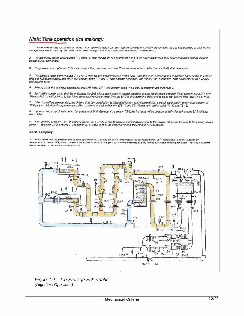
2. THERMAL ENERGY STORAGE (Partial) (See Figures 02 and 03.): a. Chilllers (See Figure 17.): Air-cooled package chillers. b. Ice tanks (See Figure 18.): Individual, ice on pipe type tanks.
Mechanical Criteria 11/29
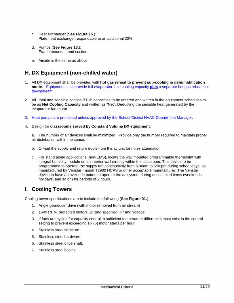
c. Heat exchanger (See Figure 15.): Plate heat exchanger, expandable to an additional 20%. d. Pumps (See Figure 13.): Frame mounted, end suction. e. Airside is the same as above.
H. DX Equipment (non-chilled water) 1. All DX equipment shall be provided with hot gas reheat to prevent sub-cooling in dehumidification
mode. Equipment shall provide full evaporator face cooling capacity plus a separate hot gas reheat coil downstream.
2. All total and sensible cooling BTUh capacities to be entered and written in the equipment schedules to
be as Net Cooling Capacity and written as “Net”. Deducting the sensible heat generated by the evaporator fan motor.
3. Heat pumps are prohibited unless approved by the School District HVAC Department Manager. 4. Design for classrooms served by Constant Volume DX equipment: a. The number of air devices shall be minimized. Provide only the number required to maintain proper
air distribution within the space.
b. Off-set the supply and return ducts from the ac unit for noise attenuation. c. For stand alone applications (non-EMS), locate the wall mounted programmable thermostat with
integral humidity module on an interior wall directly within the classroom. This device to be programmed to operate the supply fan continuously from 6:00am to 6:00pm during school days, as manufactured by Venstar (model T2900 HCPS or other acceptable manufacturer. The Venstar device to have an over-ride button to operate the ac system during unoccupied times (weekends, holidays, and so on) for periods of 2 hours.
I. Cooling Towers Cooling tower specifications are to include the following (See Figure 01.):
1. Angle gearducer drive (with motor removed from air stream)
2. 1600 RPM, protected motors utilizing specified HP and voltage.
3. If fans are cycled for capacity control, a sufficient temperature differential must exist in the control setting to prevent exceeding six (6) motor starts per hour.
4. Stainless steel structure.
5. Stainless steel hardware.
6. Stainless steel drive shaft.
7. Stainless steel basins.

Mechanical Criteria 12/29
8. Stainless steel hot water basin covers.
9. Glass reinforced polyester casing and louvers
10. OSHA approved handrail and ladder.
11. Tower shipped assembled.
12. Make-up water float valves.
13. Flow control valves.
14. 3" minimum drain constructed in the bottom of each basin.
15. Fill and eliminators to be 3" minimum clearance from basin to permit unobstructed water flow.
16. Provide variable frequency drives for fan speed control. 17. Fan motors to be inverter duty rated.
18. Include all required water treatment devices (in accordance with all applicable codes and regulations) and water treatment service, monitoring and reporting for a period of one (1) year from the date of substantial completion.
19. Waste water from the tower to discharge into the sanitary drain.
J. Training: 1. Provide a minimum of 40 hours of HVAC training to the Owner. Training hours will be tracked by the
mechanical contractor and Owner. All training must be approved by the Owner in order to be counted as actual training. All training shall be video-taped.
2. The training is to include:
a. An explanation of the basic theory of system operation with a complete sequence of operation in each design mode of operation (heat, cool, dehumidification, chilled water pumping, etc.).
b. Mechanical equipment operation and maintenance
c. Variable frequency drive operation and maintenance
d. DDC control system operation
e. Outside air and dehumidification equipment operation and maintenance 3. During the warranty period, any remaining training hours shall be provided to the school staff as needed.

Mechanical Criteria 13/29
[sample] EQUIPMENT WARRANTY [sample]
The Vendor is to reproduce this warranty on company letterhead and complete the information requested. The Vendor is the company to whom the Purchase Order was issued.
Enter Vendor Name exactly as it appears on the Contract or Purchase Order A. The Vendor hereby warrants to the Owner that the equipment and services supplied under this Contract
dated (enter the date of the Contract) are of good workmanship and of proper materials as specified in the Contract Documents, and are free from defects and suitable for the intended use.
B. The Vendor agrees to furnish labor and materials to repair or replace defective parts and products sold under
the Contract for a minimum period of twelve (12) months from the date of Warranty Commencement below. The terms of this warranty also apply to any extended warranties purchased under this Contract, as marked below:
Extended Warranty to a date 10 years from the original Warranty Commencement date
C. The Vendor agrees to respond to warranty service requests within 24 hours of notification by the Owner or
Owner's representative and to repair or replace warranted equipment within 72 hours of receipt of the request. The Vendor agrees, if directed, to provide temporary equipment as necessary to maintain acceptable conditions at no additional cost to the Owner if the repair cannot be completed within 72 hours. However, if the Vendor does not respond within 24 hours or is unable to complete the repair within 72 hours, the Vendor hereby acknowledges that the Owner has the option to proceed with the repair and agrees to reimburse the Owner for all costs.
D. This Warranty covers all labor, equipment and material costs for the removal, replacement, repairs,
shipping and handling of defective parts and the removal and replacement of the incidental equipment/materials (i.e. insulation, refrigerant, glycol, etc.).
E. The Date of Warranty Commencement is the date of Substantial Completion of the Project OR, if the date
of Substantial Completion is later than 3 months after the start-up date, the date of Start Up. Enter the Date of Warranty Commencement
F. The Vendor agrees to arrange for shipment of replacement parts via the carrier and shipping method which
will result in the fastest repair/replacement time. G. The Vendor agrees to complete and return any Registration and Start-up forms required by the
Manufacturer of the equipment within the time allowed. H. EXCEPTIONS:
1. Refrigerants, fluids, oils and expendable items such as filters, unless the loss or damage to such expendable items is the result of a failure of the equipment that is covered under this warranty.
2. This warranty does not apply to products or parts: a) which have been opened, disassembled, repaired or altered by anyone other than the vendor or its
authorized service representative or b) which have been subjected to misuse, negligence, damage, abnormal use or c) which are not an integral part of the original product furnished under this Contract or d) which have been exposed to contaminates or corrosive agents or
For warranty work, the District will contact the Vendor's representative as follows: Representative Name: Telephone Number: E-mail address: Signed/dated: Typed Name and Title of Officer or Authorized Agent:
Mechanical Criteria 14/29
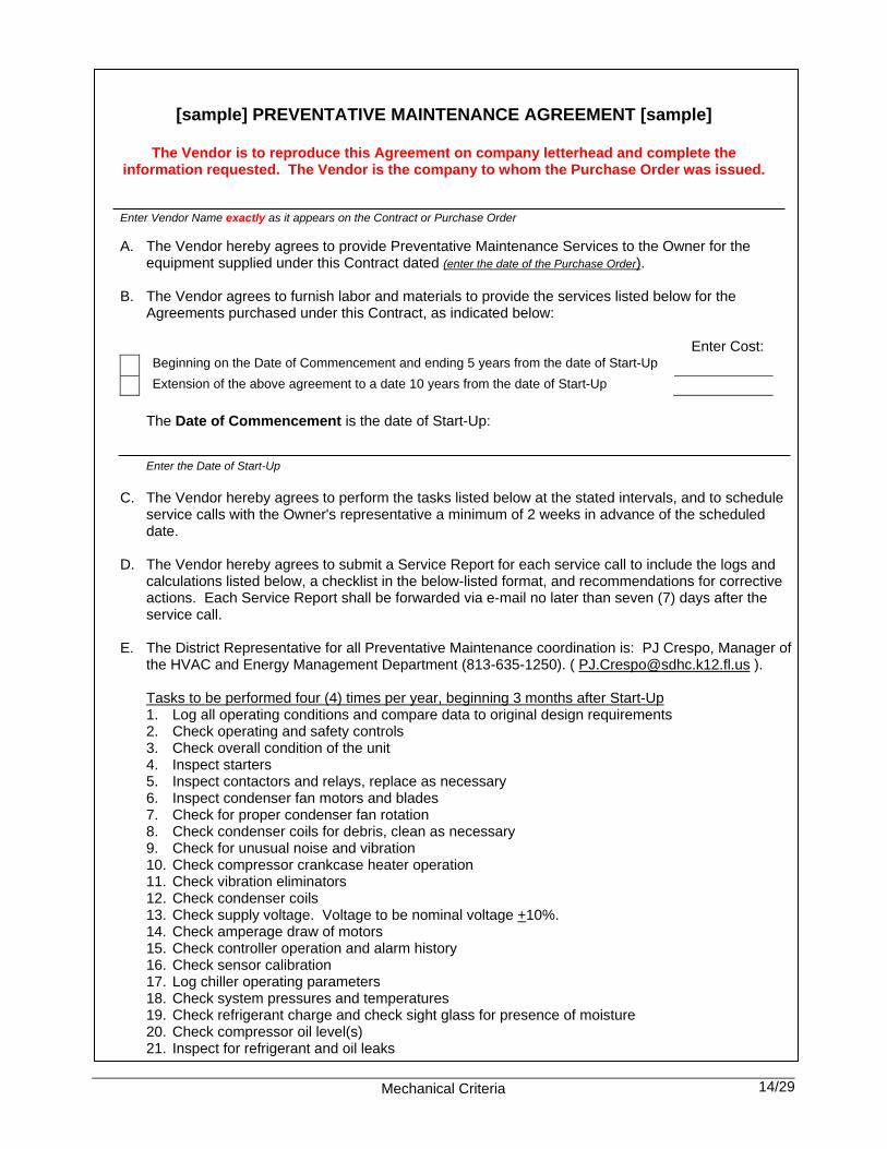
[sample] PREVENTATIVE MAINTENANCE AGREEMENT [sample]
The Vendor is to reproduce this Agreement on company letterhead and complete the information requested. The Vendor is the company to whom the Purchase Order was issued. Enter Vendor Name exactly as it appears on the Contract or Purchase Order
A. The Vendor hereby agrees to provide Preventative Maintenance Services to the Owner for the
equipment supplied under this Contract dated (enter the date of the Purchase Order). B. The Vendor agrees to furnish labor and materials to provide the services listed below for the
Agreements purchased under this Contract, as indicated below:
Enter Cost: Beginning on the Date of Commencement and ending 5 years from the date of Start-Up
Extension of the above agreement to a date 10 years from the date of Start-Up
The Date of Commencement is the date of Start-Up:
Enter the Date of Start-Up
C. The Vendor hereby agrees to perform the tasks listed below at the stated intervals, and to schedule
service calls with the Owner's representative a minimum of 2 weeks in advance of the scheduled date.
D. The Vendor hereby agrees to submit a Service Report for each service call to include the logs and
calculations listed below, a checklist in the below-listed format, and recommendations for corrective actions. Each Service Report shall be forwarded via e-mail no later than seven (7) days after the service call.
E. The District Representative for all Preventative Maintenance coordination is: PJ Crespo, Manager of
the HVAC and Energy Management Department (813-635-1250). ( [email protected] ).
Tasks to be performed four (4) times per year, beginning 3 months after Start-Up 1. Log all operating conditions and compare data to original design requirements 2. Check operating and safety controls 3. Check overall condition of the unit 4. Inspect starters 5. Inspect contactors and relays, replace as necessary 6. Inspect condenser fan motors and blades 7. Check for proper condenser fan rotation 8. Check condenser coils for debris, clean as necessary 9. Check for unusual noise and vibration 10. Check compressor crankcase heater operation 11. Check vibration eliminators 12. Check condenser coils 13. Check supply voltage. Voltage to be nominal voltage +10%. 14. Check amperage draw of motors 15. Check controller operation and alarm history 16. Check sensor calibration 17. Log chiller operating parameters 18. Check system pressures and temperatures 19. Check refrigerant charge and check sight glass for presence of moisture 20. Check compressor oil level(s) 21. Inspect for refrigerant and oil leaks

Mechanical Criteria 15/29
Preventative Maintenance Agreement – Continued 22. Check chilled water flow switch operation 23. Inspect pump seal 24. Check accuracy of thermistors, replace if > +2o F (1.2o C) variance from calibrated thermometer 25. Check accuracy of transducers, replace if > +5 psi (34.47kPa) variance 26. Check that proper concentration of glycol is present in the chilled water loop where applicable 27. Check refrigerant filter driers for excessive pressure drop, replace as necessary 28. Check chilled water strainers, clean as necessary 29. Provide a report to the Owner, to include the logs and calculations required above, and a
checklist in the above-listed format and recommendations for corrective actions.
In addition to the above, perform these tasks at the 4th visit. These tasks are to be performed yearly within 2 weeks of the Start-Up date: 1. Conduct refrigerant leak test and repair minor leaks 2. Inspect condenser fan mounting hardware 3. Lubricate the condenser fan bearings 4. Meg hermetic motors 5. Check and tighten electrical connections 6. Check tightness of the motor terminal connections 7. Clean condenser coils 8. Check for software upgrades 9. Calculate refrigerant loss rate 10. Test the low water temperature control device. Calibrate and record setting 11. Test the oil pressure safety device(s). Calibrate and record setting 12. Test oil for acid content and discoloration 13. Clean motor starter and cabinet 14. Check condition of the contacts for wear and pitting 15. Verify the operation of electrical interlocks
It is the Owner's intent to issue a separate purchase order each year that the Preventative Maintenance Agreement is extended. Note: Payment for Preventative Maintenance Services is payable upon the completion of each service call and associated Service Report. Amounts attributable to each service call will be pro-rated according to the number of service calls scheduled under the yearly purchase order. Invoices will be directed to the District Representative and will reference
1) the number of the Purchase Order and 2) the date of the Service Report(s) for which payment is due.
For preventative maintenance work, the District will contact the Vendors representative as follows:
For warranty work, the District will contact the Vendor's representative as follows: Representative Name: Telephone Number: E-mail address: Signed/dated: Typed Name and Title of Officer or Authorized Agent:

Mechanical Criteria 11/29
Figure 01 - Cooling Tower Piping Diagram (Total Piping Schematic)
Mechanical Criteria 12/29
Figure 02 – Ice Storage Schematic (Nighttime Operation)

Mechanical Criteria 13/29
Figure 03 – Ice Storage Schematic (Daytime Operation)

Mechanical Criteria 14/29
Figure 04 – Pump Detail
Mechanical Criteria 15/29
Figure 05 – Vari-prime Pumping Diagram
Mechanical Criteria 16/29
Figure 06 – Piping Connections (No Bull-Heading)

Mechanical Criteria 17/29
Figure 07 – Kitchen Ventilation / Tempering Systems

Mechanical Criteria 18/29
Figure 08 – Kiln Room Ventilation Systems

Mechanical Criteria 19/29
Figure 08a – Kiln Wiring Schematic Diagram

Mechanical Criteria 20/29
Figure 09 – Outside Make-up Air Control Diagram

Mechanical Criteria 21/29
Figure 10 – Gym Ventilation With & Without Locker Rooms

Mechanical Criteria 22/29
Figure 11 – Gym Duct Layout (Single Duct Design)

Mechanical Criteria 23/29
Figure 12 – Gym Duct Layout (Twin Duct Design)

Mechanical Criteria 24/29
Figure 13 – Standard Pump Schedule

Mechanical Criteria 25/29
Figure 14 – Standard Variable Frequency Drive Schedule

Mechanical Criteria 26/29
Figure 15 – Standard Heat Exchanger Schedule

Mechanical Criteria 27/29
Figure 16 – Standard Air Handler Schedule

Mechanical Criteria 28/29
Figure 17 – Standard Air Cooled Chiller Schedule

Mechanical Criteria 29/29
Figure 18 – Standard Ice Storage Tank Schedule