150W AC/DC Power Supply Unit Instruction Manual · 150W AC/DC Power Supply Unit Instruction Manual...
32
150W AC/DC Power Supply Unit Instruction Manual Page 1 Copyright © 2016, New Japan Radio Co., Ltd. All rights reserved. This instruction manual may not be reproduced, in part or in whole, without the permission of New Japan Radio Co., Ltd. The specifications and information regarding the products in this instruction manual are subject to change without notice. All statements, information, and recommendations in this instruction manual are believed to be accurate but are presented without warranty of any kind, express, or implied. Users must take full responsibility for their application of any products. Document Part Number: IM-Z1286 Revision: 08 Issue Date: September 05, 2016 IM-Z1286 Rev.08 150W AC/DC Power Supply Unit Instruction Manual
Transcript of 150W AC/DC Power Supply Unit Instruction Manual · 150W AC/DC Power Supply Unit Instruction Manual...

150W AC/DC Power Supply Unit Instruction Manual Page 1
Copyright © 2016, New Japan Radio Co., Ltd. All rights reserved.This instruction manual may not be reproduced, in part or in whole,
without the permission of New Japan Radio Co., Ltd.
The specifications and information regarding the products in thisinstruction manual are subject to change without notice.All statements, information, and recommendations in this
instruction manual are believed to be accurate but are presentedwithout warranty of any kind, express, or implied.
Users must take full responsibility for their application of anyproducts.
Document Part Number: IM-Z1286
Revision: 08
Issue Date: September 05, 2016
IM-Z1286 Rev.08
150W AC/DC Power Supply UnitInstruction Manual

150W AC/DC Power Supply Unit Instruction Manual Page 2
August 01, 2013September 05, 2016
DATEJanuary 28, 2010August 20, 2010
December 16, 2010November 09, 2011
December 18, 2012July 10, 2013
Revised for CAUTION of page 22.
Rack-moount kit revised
07 Revised for Rack-mount Kit of NJZ1286N
01 Initial Release (for Engineering Sample)REV DESCRIPTION
・Add Note:1, Change of Note No(Note:1→2,Note:2→3) ・3. Packing List:Delete of No6 Coaxial cable, Change of List No(7→6,8→7,9→8,) ・6.2.1. AC Power Cable Add Note
06 Added the BUC line-up of NJT5763NA andNJT5763FA
08
02 Revised for production03 Revised at Connection and Installation04
05
Revision Record
IM-Z1286 Rev.08

150W AC/DC Power Supply Unit Instruction Manual Page 3
1.
2.
3.
4.
5.
General Caution
IM-Z1286 Rev.08
NJRC strives to produce reliable and high quality microwave components.NJRC's microwave components are intended for specific applications andrequire proper maintenance and handling. To enhance the performanceand service of NJRC's microwave components, the devices, machinery orequipment into which they are integrated should undergo preventativemaintenance and inspection at regularly scheduled intervals. Failure toproperly maintain equipment and machinery incorporating these productscan result in catastrophic system failures.
NJRC offers a variety of microwave components intended for particularapplications. It is important that you select the proper component for yourintended application. You may contact NJRC's sales office or salesrepresentatives, if you are uncertain about the products listed in thecatalog and the specification sheets.
Special care is required in designing devices, machinery or equipment,which demand high levels of reliability. This is particularly important whendesigning critical components or systems whose foreseeable failure canresult in situations that could adversely affect health or safety. Indesigning such critical devices, equipment or machinery, carefulconsideration should be given to, amongst other things, their safetydesign, fail-safe design, back-up and redundancy systems, and diffusiondesign.
To ensure the highest levels of reliability, NJRC products must always beproperly handled. The introduction of external contaminants (e.g. dust, oilor cosmetics) can result in failures of microwave components.
The products listed in the catalog and specification sheets may not beappropriate for use in certain equipment where reliability is critical orwhere the products may be subjected to extreme conditions. You shouldconsult our sales office or sales representatives before using the productsin any of the following types of equipment.* Aerospace Equipment* Equipment Used in the Deep Sea* Power Generator Control Equipment (nuclear, steam, hydraulic)* Life Maintenance Medical Equipment* Fire Alarm/Intruder Detector* Vehicle Control Equipment (automobile, airplane, railroad, ship, etc.)* Various Safety Equipment

150W AC/DC Power Supply Unit Instruction Manual Page 4
6.
General Caution (countined)
NJRC's products have been designed and tested to function withincontrolled environmental conditions. Do not use products under conditionsthat deviate from methods or applications specified in the catalog andspecification sheets. Failure to employ NJRC's products in the properapplications can lead to deterioration, destruction or failure of theproducts. NJRC shall not be responsible for any bodily injury, fires oraccidents, property damage or any consequential damages resulting fromthe misuse or misapplication of its products. PRODUCTS ARE SOLDWITHOUT WARRANTY OF ANY OF KIND, EITHER EXPRESS OR IMPLIED,INCLUDING BUT NOT LIMITED TO ANY IMPLIED WARRANTY OFMERCHANTABILITY OR FITNESS FOR A PARTICULAR PURPOSE.
IM-Z1286 Rev.08

150W AC/DC Power Supply Unit Instruction Manual Page 5
6
7 - 9
8. Specification ………………………………………………………………………………
10
11 - 12
18 - 25
26 - 30
31 - 32
7. Maintenance ………………………………………………………………………………
6. Connection and Installation ………………………………………………………
5. Physical Description …………………………………………………………………
2. Safety Instructions ……………………………………………………………………
4. Overview ……………………………………………………………………………………
3. Packing List ………………………………………………………………………………
13 - 17
Updated instruction manual may be available from NJRC's sales [email protected].
This instruction manual describes 150W AC/DC Power Supply Unit (PSU) forNJRC's C-band 10W and Ku-band 8W BUC (Model No.: NJT5762N, NJT5762F,NJT5763N, NJT5763F,NJT5118N, NJT5118F, NJT5218N, and NJT5218F) hereinreferred to as "the Unit".
Contents
About This Instruction Manual
This instruction manual provides information and instructions for installation andoperation of the Unit.
1. Introduction ………………………………………………………………………………
IM-Z1286 Rev.08
This instruction manual is intended for use by trained field installers or systemengineers responsible for satellite networks.

150W AC/DC Power Supply Unit Instruction Manual Page 6
NJZ1286F
NJT5762F NJZ1286FNJT5762NA NJT5762N NJZ1286N
NJT5763NA NJT5763N NJZ1286N
The Unit comes in an alminium-housing with corrosion-proof treatment,assumingthe indoor use. The Unit receives and transmits 10 MHz reference and IF signal(L-Band: 950 - 1450 MHz or 950 - 1750 MHz). The Unit supply +48 V DC poweron a output connector. The Unit has N-Type or F-type connectors input for 10 MHzreference and IFsignal, output for DC power, 10 MHz reference and IF signal, andIEC320-C14 inlet input for AC power (100 to 240 VAC).
NJT5762FA
IM-Z1286 Rev.08
1. Introduction
This instruction manual is for 150W AC/DC PSU for NJRC's C-band 10W and Ku-band 8W BUC (Model No.: NJT5762N, NJT5762F, NJT5763N, NJT5763F,NJT5118N,NJT5118F, NJT5218N, and NJT5218F).
NJT5118N NJZ1286NNJT5118FA
1.1. Model Number
Product Model NumberModel Number
NJT5218FA NJT5218F NJZ1286F
NJT5118NANJT5118FNJT5218N NJZ1286NNJT5218NA
BUC 150W AC/DC PSU
The Unit is constructed by a 150W AC/DC power supply and a bias-tee whichapplies +48 V DC power and passes through 10 MHz reference and IF signal (L-band: 950 - 1450 MHz or 950 - 1750 MHz).
NJT5763FA NJT5763F NJZ1286F

150W AC/DC Power Supply Unit Instruction Manual Page 7
CAUTION
DANGERSymbol
DANGER, WARNING, CAUTION, and NOTE Statements
NOTE
CAUTION indicates a potentiallyhazardous situation which, if notavoided, could result in minor ormoderate injury. CAUTION mayalso be used to indicate otherunsafe practices or risks ofproperty damage.NOTE is used to notify ofinstallation, operation, ormaintenance information that isimportant, but not hazard-related.
IM-Z1286 Rev.08
Statement
WARNING indicates a potentiallyhazardous situation which, if notavoided, could result in death orserious injury.
Use the following safety guidelines to help protect the Unit from potentialdamage and to help ensure your own personal safety.
2. Safety Instructions
DANGER, WARNING, CAUTION, and NOTE statements are usedthroughout this instruction manual to emphasize important and criticalinformation. You must read these statements to help ensure safety andto prevent product damage. The statement are defined below.
WARNING
DescriptionDANGER indicates an imminentlyhazardous situation which, if notavoided, will result in death orserious injury.
150W AC/DC Power Supply Unit Instruction Manual Page 8
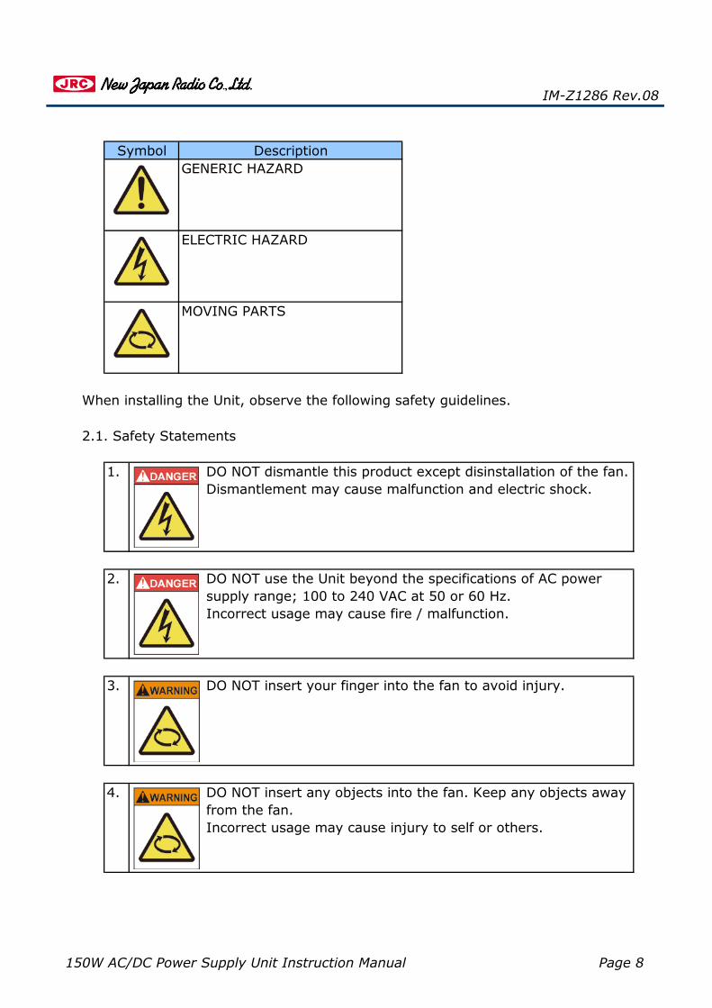
DO NOT insert any objects into the fan. Keep any objects awayfrom the fan.Incorrect usage may cause injury to self or others.
DO NOT use the Unit beyond the specifications of AC powersupply range; 100 to 240 VAC at 50 or 60 Hz.Incorrect usage may cause fire / malfunction.
DO NOT dismantle this product except disinstallation of the fan.Dismantlement may cause malfunction and electric shock.
When installing the Unit, observe the following safety guidelines.
GENERIC HAZARD
IM-Z1286 Rev.08
2.1. Safety Statements
3.
4.
DO NOT insert your finger into the fan to avoid injury.
1.
2.
MOVING PARTS
ELECTRIC HAZARD
Symbol Description
150W AC/DC Power Supply Unit Instruction Manual Page 9
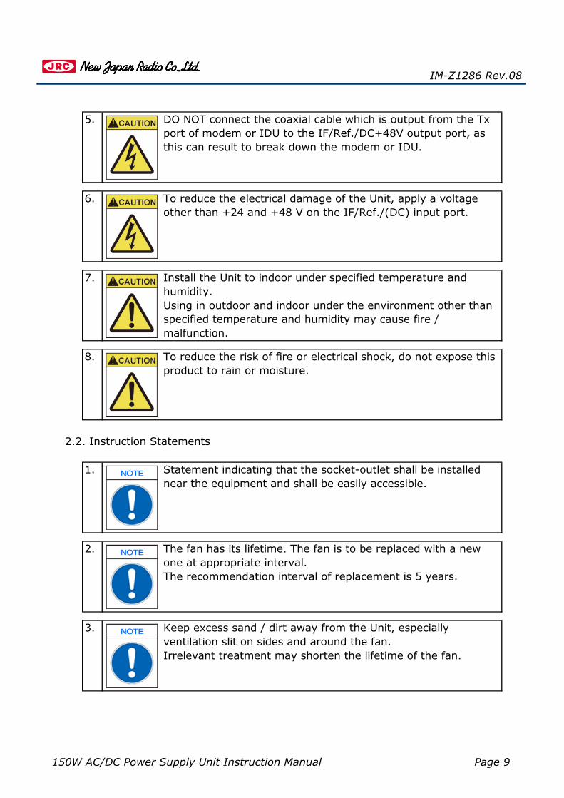
1. Statement indicating that the socket-outlet shall be installednear the equipment and shall be easily accessible.
2. The fan has its lifetime. The fan is to be replaced with a newone at appropriate interval.The recommendation interval of replacement is 5 years.
Keep excess sand / dirt away from the Unit, especiallyventilation slit on sides and around the fan.Irrelevant treatment may shorten the lifetime of the fan.
7.
8. To reduce the risk of fire or electrical shock, do not expose thisproduct to rain or moisture.
IM-Z1286 Rev.08
To reduce the electrical damage of the Unit, apply a voltageother than +24 and +48 V on the IF/Ref./(DC) input port.
Install the Unit to indoor under specified temperature andhumidity.Using in outdoor and indoor under the environment other thanspecified temperature and humidity may cause fire /malfunction.
3.
2.2. Instruction Statements
DO NOT connect the coaxial cable which is output from the Txport of modem or IDU to the IF/Ref./DC+48V output port, asthis can result to break down the modem or IDU.
5.
6.
150W AC/DC Power Supply Unit Instruction Manual Page 10
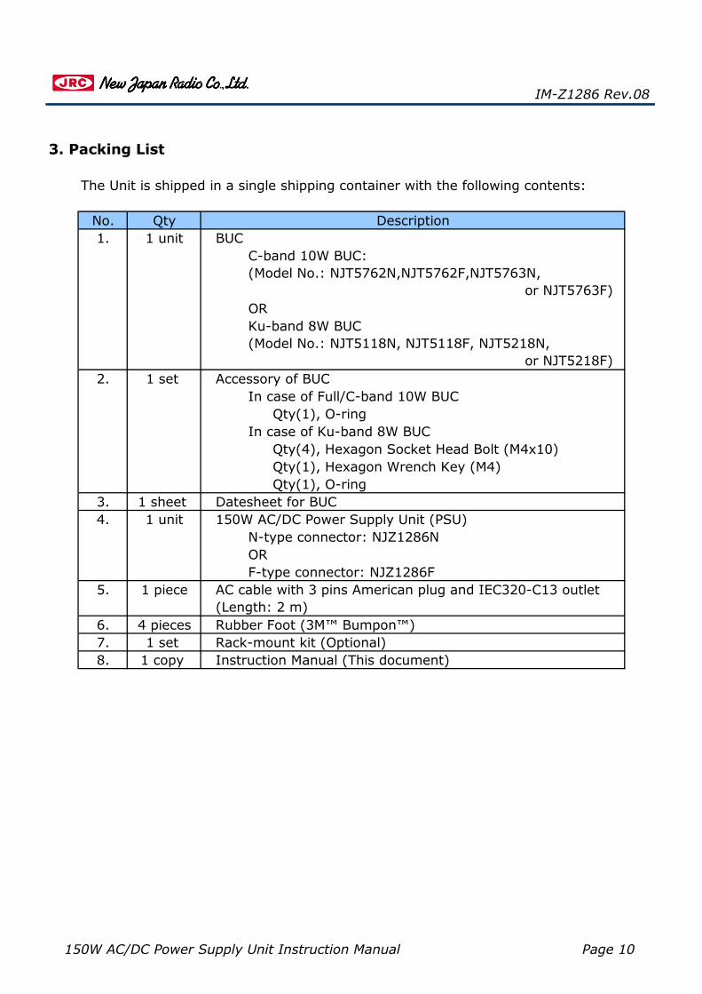
6. 4 pieces Rubber Foot (3M™ Bumpon™)
IM-Z1286 Rev.08
3. Packing List
The Unit is shipped in a single shipping container with the following contents:
2. Accessory of BUC
1 sheet Datesheet for BUC150W AC/DC Power Supply Unit (PSU)
BUCC-band 10W BUC:(Model No.: NJT5762N,NJT5762F,NJT5763N, or NJT5763F)
Qty(4), Hexagon Socket Head Bolt (M4x10)
1 set
4.
1.No.
1 set
ORKu-band 8W BUC(Model No.: NJT5118N, NJT5118F, NJT5218N, or NJT5218F)
Rack-mount kit (Optional)7.
3.1 unit
5. 1 piece
Qty(1), Hexagon Wrench Key (M4)Qty(1), O-ring
In case of Full/C-band 10W BUCQty(1), O-ring
Qty Description
8. 1 copy
In case of Ku-band 8W BUC
F-type connector: NJZ1286FAC cable with 3 pins American plug and IEC320-C13 outlet(Length: 2 m)
Instruction Manual (This document)
N-type connector: NJZ1286NOR
1 unit

150W AC/DC Power Supply Unit Instruction Manual Page 11
・
・
・
・
・
・
・
4. Overview
IM-Z1286 Rev.08
The Unit provides a DC power via a coaxial cable to operate NJRC’s Full/C-band10W and Ku-band 8W BUC.
To keep supplying DC power regardless of modem output status.Option 1:
Option 2:
Diagram of Connecting among Modem, BUC, and 150W AC/DC PSU
To control power DC output on/off by synchronization of input DCvoltage on/off from modem.
Unique features:
One coaxial cable solution.
Compatible with 1U rack-mount.
The mode of DC power output can be selected out of in the following modeoptions by DIP switch on the front panel.
Directly connect the coaxial cable for IF signal, 10 MHz reference and DCpower from modem.
Indoor power supply unit with up to 150 W and +48 V DC power output.
For any types of modem.
DC power output can be turned on/off by mechanical switch on the front

150W AC/DC Power Supply Unit Instruction Manual Page 12
IM-Z1286 Rev.08
Schematic Diagram of Inside AC/DC Power Supply

150W AC/DC Power Supply Unit Instruction Manual Page 13
5.1. Appearance
Rear View of 150W AC/DC PSU(N-type Female Connector Model)
5. Physical Description
IM-Z1286 Rev.08
This section describes appearance and outline of the Unit.
Front View of 150W AC/DC PSU
150W AC/DC Power Supply Unit Instruction Manual Page 14
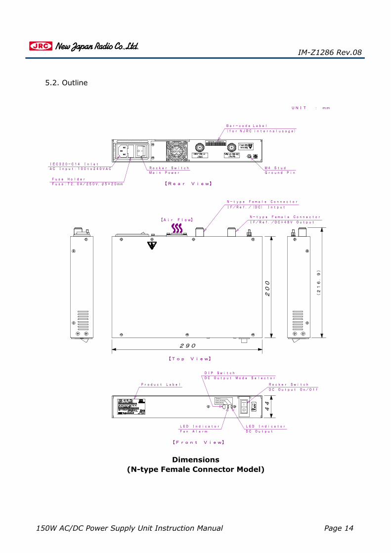
Dimensions(N-type Female Connector Model)
IM-Z1286 Rev.08
5.2. Outline
IF/Ref./(DC) Intput
IF/Ref./DC+48V Output
N-type Female Connector
N-type Female Connector
Main PowerRocker Switch
IEC320-C14 InletM4 Stud
Product Label
DC Output On/Off
Rocker Switch
DIP Switch
LED IndicatorLED Indicator
Ground Pin
Fuse:T2.0A/250V,φ5×20mm
Fuse Holder
Bar-code Label
(for NJRC internalusage)
AC Input:100to240VAC
【Rear View】
【Front View】
【Top View】
【Air Flow】
DC OutputFan Alarm
DC Output Mode Selector
UNIT : mm
20
0
Power
Fan Alarm
Mode Select
CAUTION:Forcontinuedprotectionagainstriskoffire,
replaceonlywithsametypeandratingoffuse.
FUSE
250V
T2.0A
290
44
(2
16
.9
)

150W AC/DC Power Supply Unit Instruction Manual Page 15
Dimensions(F-type Female Connector Model)
IM-Z1286 Rev.08
IF/Ref./(DC) Intput
IF/Ref./DC+48V Output
UNIT : mm
Main PowerRocker Switch
IEC320-C14 InletM4 Stud
DC Output On/Off
Rocker Switch
DIP Switch
Ground Pin
Fuse:T2.0A/250V,φ5×20mm
Fuse Holder
AC Input:100to240VAC
【Air Flow】
F-type Female Connector
F-type Female Connector
Product Label
LED IndicatorLED Indicator
Bar-code Label
(for NJRC internalusage)
【Rear View】
【Front View】
【Top View】
DC OutputFan Alarm
DC Output Mode Selector
(2
13
.2
)
(2
11
.8
)
200
44
290
FUSE
250V
T2.0A
replaceonlywithsametypeandratingoffuse.CAUTION:Forcontinuedprotectionagainstriskoffire,
Mode Select
Fan Alarm
Power

150W AC/DC Power Supply Unit Instruction Manual Page 16
IM-Z1286 Rev.08
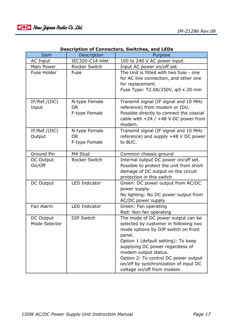
5.3. Description of Connectors, Switches, and LEDs
Location of Connectors, Switches, and LEDs
【FRONT VIEW】
【REAR VIEW】
Product Label
DIP SwitchDC Output Mode Selector
LED IndicatorDC Output
LED IndicatorFAN Alarm
Rocker SwitchDC Output On/Off
M4 StudGround Pin
F-type(N-type)Female ConnectorIF/Ref./(DC) Input
F-type(N-type)Female ConnectorIF/Ref./DC+48V Output
IEC320-C14 InletAC Input:100 to 240VAC
Fuse HolderFuse:T2 .0A/250V Φ5x20mm
Rocker SwitchMain Power
【Fan Flow】
150W AC/DC Power Supply Unit Instruction Manual Page 17
Red: Non fan operating
Green: DC power output from AC/DCpower supplyNo lighting: No DC power output fromAC/DC power supply
Fan Alarm Green: Fan operating
Main Power
N-type FemaleORF-type Female
M4 Stud
LED Indicator
Rocker Switch
Fuse Holder
IF/Ref./(DC)Input
IF/Ref./(DC)Output
DC OutputOn/Off
DC Output
Rocker Switch
Transmit signal (IF signal and 10 MHzreference) and supply +48 V DC powerto BUC.
Fuse The Unit is fitted with two fuse - onefor AC line connection, and other onefor replacement.Fuse Type: T2.0A/250V, φ5 x 20 mm
Transmit signal (IF signal and 10 MHzreference) from modem or IDU.Possible directly to connect the coaxialcable with +24 / +48 V DC power frommodem.
Input AC power on/off set.
DescriptionIEC320-C14 inlet
Purpose100 to 240 V AC power input.
Internal output DC power on/off set.
LED Indicator
N-type FemaleORF-type Female
The mode of DC power output can beselected by customer in following twomode options by DIP switch on frontpanel.Option 1 (default setting): To keepsupplying DC power regardless ofmodem output status.Option 2: To control DC power outputon/off by synchronization of input DCvoltage on/off from modem.
Common chassis ground
DC OutputMode Selector
DIP Switch
Ground Pin
Item
Possible to protect the unit from shortdamage of DC output on the circuitprotection in this switch
AC Input
IM-Z1286 Rev.08
Description of Connectors, Switches, and LEDs
150W AC/DC Power Supply Unit Instruction Manual Page 18
・
・
・
・
・
・
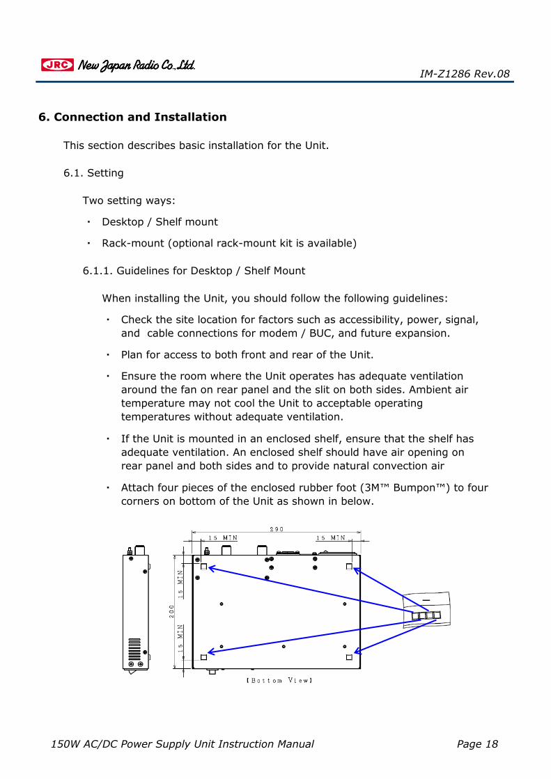
・ Attach four pieces of the enclosed rubber foot (3M™ Bumpon™) to fourcorners on bottom of the Unit as shown in below.
Two setting ways:
Check the site location for factors such as accessibility, power, signal,and cable connections for modem / BUC, and future expansion.
When installing the Unit, you should follow the following guidelines:
Plan for access to both front and rear of the Unit.
Desktop / Shelf mount
Rack-mount (optional rack-mount kit is available)
6.1.1. Guidelines for Desktop / Shelf Mount
6.1. Setting
Ensure the room where the Unit operates has adequate ventilationaround the fan on rear panel and the slit on both sides. Ambient airtemperature may not cool the Unit to acceptable operatingtemperatures without adequate ventilation.
6. Connection and Installation
This section describes basic installation for the Unit.
IM-Z1286 Rev.08
If the Unit is mounted in an enclosed shelf, ensure that the shelf hasadequate ventilation. An enclosed shelf should have air opening onrear panel and both sides and to provide natural convection air

150W AC/DC Power Supply Unit Instruction Manual Page 19
・
・
・
・
・
Check the site location for factors such as accessibility, power, signal,and cable connections for modem / BUC, and future expansion.
The Unit with the optional rack-mount kit requires a minimum of 1U(44 mm) of vertical rack spaces. You should measure the proposedrack location before mounting the chassis.
When installing the Unit, you should follow the following guidelines:
Plan for access to both front and rear of the Unit.
If the Unit is mounted in an enclosed shelf, ensure that the shelf hasadequate ventilation. An enclosed shelf should have air opening onrear panel and both sides and to provide natural convection air
Ensure the room where the Unit operates has adequate ventilationaround the fan on rear panel and the slit on both sides. Ambient airtemperature may not cool the Unit to acceptable operatingtemperatures without adequate ventilation.
6.1.2. Guidelines for Rack-mount
IM-Z1286 Rev.08
The Unit can only be flush-mounted in the 19 inch rack using the optionalrack-mount kit. The Unit can be mounted with the front of the chassispanel facing outward toward the aisle.

150W AC/DC Power Supply Unit Instruction Manual Page 20
DescriptionRack-mount Flange
Rack-mount Kit (Optional):
No. Qty
2. 4 pieces M4X10mm flat Head Screw 1.
Using #2 phillips screwdriver, remove and save four M4 flathead screws as shown in below.
IM-Z1286 Rev.08
2 pieces
Step 2:
Flush-mounting the Unit in the 19 inch rack is proceed with the followingsteps:
Tools Required: #2 phillips screwdriver
Step 1:
Position the rack-mount flanges (Rack-mount Kit: No. 1) bothsides of the Unit as shown in below.Install four M4X10mm flat head screws to flanges and the Unit.

150W AC/DC Power Supply Unit Instruction Manual Page 21
・
・
・
・
Check that the rocker switch of "Main Power" on the rear paneland the "DC Output On/Off" on the front panel are to be
6.2. Connection
Step 1:
Statement indicating that the socket-outlet shall be installednear the equipment and shall be easily accessible.
Three cables and one wire:
10 MHz reference and IF signal (L-band: 950 - 1450 MHz or 950 - 1750MHz) are input from Modem to BUC by way of the Unit.
6.2.2. Coaxial Cable from Modem or IDU to the Unit
Connection of the coaxial cable among modem and the Unit are describedby the following steps:
Step 1: Connect a coaxial cable with N-type or F-type male connectorsto the IF/Ref./(DC) input port on the rear panel of the Unit asshown in the diagram of subsequent page.
Step 2: Connect the AC power cable (3 pins American plug) to IEC320-C14 inlet on the rear panel.In case of a different type of outlet from 3 pins American plug,employ a conversion plug suitable to the outlet instead.
Coaxial Cable from Modem or IDU to the Unit
IM-Z1286 Rev.08
AC Power Cable
Coaxial Cable from the Unit to BUC
Wire for Common Chassis Ground
6.2.1. AC Power Cable
The Unit is directly powered by AC power source (100-240V). Low noise /low transient AC power source is recommended.
Connection of AC power cable is to be proceeded as it follows:

150W AC/DC Power Supply Unit Instruction Manual Page 22
Connect the cable to TX port of modem or IDU.
Connecting coaxial cable from the Unit to BUC is proceed with the followingsteps:
IM-Z1286 Rev.08
In order to prevent the electrical damage of the Unit, avoid toapply a voltage of +60 V and more on the IF/Ref./(DC) inputport.
Step 1: Connect a coaxial cable with N-type or F-type male connectorto the IF/Ref./DC+48V output port on rear panel as shown inbelow.
6.2.3. Coaxial Cable from the Unit to BUC
Step 2:
The Unit can be supply +48 V DC power of the internal AC/DC powersupply to BUC, and passed through 10 MHz reference, an IF signal (L-band: 950 - 1450 MHz or 950 - 1750 MHz) from modem or IDU to BUC.
IF/Ref./DC+48V OutputTo BUC
IF/Ref./(DC) InputFrom Modem
Ground Pin
Connect the coaxial cable which connects to the BUC.
IF/Ref./DC+48V OutputTo BUC
IF/Ref./(DC) InputFrom Modem
Ground Pin
Connect the coaxial cable which connectsto the Tx port of modem or IDU.

150W AC/DC Power Supply Unit Instruction Manual Page 23
Connecting wire for common chassis ground from the chassis ground ofthe other equipment is proceed with the following step:
6.2.4. Wire for Common Chassis Ground
IM-Z1286 Rev.08
Step 2: Connect the cable to BUC.
Step: Connect the wire from ground on the other equipment to theground pin stud on rear panel.
The Unit can be had the chassis ground of the other equipment (e.g.modem) in common.
DO NOT connect the coaxial cable which is output from the Txport of modem or IDU to the IF/Ref./DC+48V output port, asthis can result to break down the modem or IDU.

150W AC/DC Power Supply Unit Instruction Manual Page 24
・
・
When changing setting of DIP switch, turn off the main powerby rocker switch on rear panel and do not use pincette.If changing setting of DIP switch with the Unit operated or bypincette this can result to break down the Unit.
IM-Z1286 Rev.08
Option 1 (default setting): To keep supplying DC power regardless ofmodem output status.
The mode of DC power output can be selected by customer in following twomode options:
6.3. Configuring the Mode of DC Power Output
In case of outputting DC power with mode of option 1, you do not need toconfigure the factory default setting of DIP switch on front panel.
Option 2: To control power DC output on/off by synchronization of inputDC voltage on/off from modem.
However, if the Unit outputting DC power with mode of option 2, you need tochange DIP switch on front panel from top side to bottom side by a pointed jig(e.g. needle) as shown in below
【TOP】DIP Switch
【BOTTOM】
DC Output Mode Selector

150W AC/DC Power Supply Unit Instruction Manual Page 25
・
・
・ ・ ・
6.4. Start-up
Step 2:
Start-up the Unit is proceed with the following steps:
6.5. Recommendation Coaxial Cable from the Unit to BUC
Step 1:
IM-Z1286 Rev.08
In terms of satisfying that the Unit output less than 150 W DC power, and aninput voltage of BUC is more than 18 V. The following cables which totalresistance* is 30 ohms/km or less are recommended:(*Note: Total resistance means sum number of both conductor and outershield resistance.)
You need to choose type and length of the coaxial cable from the Unit to BUCto satisfy that the Unit output less than 150 W DC power, and an input voltageof BUC is more than 18 V.On choice of type and length of the coaxial cable, you need to consider RFinsertion loss between the Unit and BUC in accordance with modem or IDU
Turn on the rocker switch of the main power on rear panel, thenthe fan on rear panel starts to circle and LED indicator of the fanalarm on front panel lights green.
Turn on the rocker switch of DC output on/off on front panel, thenLED indicator of the DC output on front panel lights green and DCpower is output under the DC power output mode.
+81-49-278-1270
Contact to us by phone, fax, or email, if further information is needed beyondthe coverage of this instruction manual on the recommendation coaxial cable.
RG-11 (Total Resistance: around 13 ohms/km)
RG-6 (Total Resistance: around 30 ohms/km)
If total resistance of your chosen cable is less than 30 ohms/km, you caninstall the cable of up to 200m (650 feet) between the unit and BUC.
Email: [email protected]
Telephone:Fax: +81-49-278-1234
150W AC/DC Power Supply Unit Instruction Manual Page 26
・
・
・ ・ ・
The Unit indicates the fan alarm by LED indicator on front panel with red lightemission, you need to replace a new fan by yourself in field. And the fan is tobe replaced with a new one at five years interval.
Telephone: +81-49-278-1270
Contact to us by phone, fax, or email, when a new fan for replacement isneeded.
+81-49-278-1234Email: [email protected]
Regular dusting / dust removal will ensure the Unit to operate withinoperational specification.
Use a slightly damp cloth with excess moisture wringed out (not saturated,wet or dripping cloth) to wipe away the dust that collects on the outside ofthe enclosure
A high, dusty environment will require frequent maintenance of vacuumingthe dust off the enclosure vents and circuit board.
This Section describes basic maintenance for the Unit.
IM-Z1286 Rev.08
7. Maintenance
7.1. Dust Removal
The Unit is Forced Air by fan on rear panel for cooling.
The fan has its lifetime. The fan is to be replaced with a newone at appropriate interval.The recommendation interval of replacement is 5 years.
7.2. Fan Field Replacement
Fax:

150W AC/DC Power Supply Unit Instruction Manual Page 27
The replacement of fan is proceed with the following steps:
IM-Z1286 Rev.08
You must be very careful when replacing a fun to avoid beingshocked or damaging the circuit. The following safetyprecautions will protect you and the equipment you are using.
· Turn the power off, disconnect the AC power cable, anddischarge the circuit before removing a fan.
· When you remove a fan and fit in a new one , be careful toavoid shocks and short circuits.
Turn off the rocker switch of the main power on rear panel, anddisconnect the AC power cable from the Unit.
Tools Required: #2 Philips screwdriver
Step 1:
Step 2: Using #2 Philips screwdriver, remove 6 pan head screws withwashers, and save the screws, a finger guard over fan, and a coverover fan cable as shown in below.
Pan Head Screw(6)
FAN FAN Cable
Coverfor Fan Cable
Screws withWashers(2)
for fixing CoverScrews with Washers(6)for fixing Fan
Finger Guard
150W AC/DC Power Supply Unit Instruction Manual Page 28
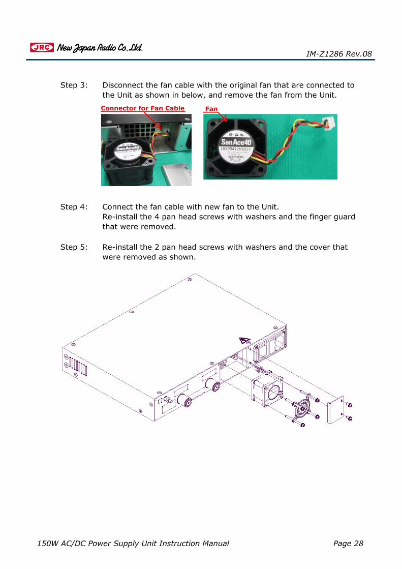
Step 3: Disconnect the fan cable with the original fan that are connected tothe Unit as shown in below, and remove the fan from the Unit.
Step 4: Connect the fan cable with new fan to the Unit.Re-install the 4 pan head screws with washers and the finger guardthat were removed.
IM-Z1286 Rev.08
Step 5: Re-install the 2 pan head screws with washers and the cover thatwere removed as shown.

150W AC/DC Power Supply Unit Instruction Manual Page 29
IM-Z1286 Rev.08
7.3. Fuse Field Replacement
Close the fuse holder, connect the AC power cable to the Unit, andTurn on the rocker switch
Step 2: Open the fuse holder next to the IEC320-C14 inlet, and replace in-use fuse (blown fuse) with stock fuse or new one. See figure
If the Unit is overloaded and the fuse is blown, you need to replace a new fuseby yourself in field in order to operate normally.
The Unit is fitted with a fuse for AC line connection. The fuse are containedwithin the holder of the AC power inlet connector, behind a small plastic flap.The Unit has one other use for replacement. ・Fuse Type: T2.0A/250V, φ5 x 20 mm
You must be very careful when replacing a fuse to avoid beingshocked or damaging the circuit. The following safetyprecautions will protect you and the equipment you are using.
· Turn the power off, disconnect the AC power cable, anddischarge the circuit before removing a fuse.
· When you remove a fuse and fit in a new one , be careful toavoid shocks and short circuits.
Step 1: Turn off the rocker switch of the main power on rear panel, anddisconnect the AC power cable from the Unit.
Step 3:
The replacement of fuse is proceed with the following steps:
Fuse Holder
In-Use Fuse
Stock Fuse
150W AC/DC Power Supply Unit Instruction Manual Page 30
・ ・ ・
Fax: +81-49-278-1234+81-49-278-1270
Email:
Telephone:
IM-Z1286 Rev.08
Contact to us by phone, fax, or email, if further information is needed beyond thecoverage of this instruction manual on the maintenance.
150W AC/DC Power Supply Unit Instruction Manual Page 31
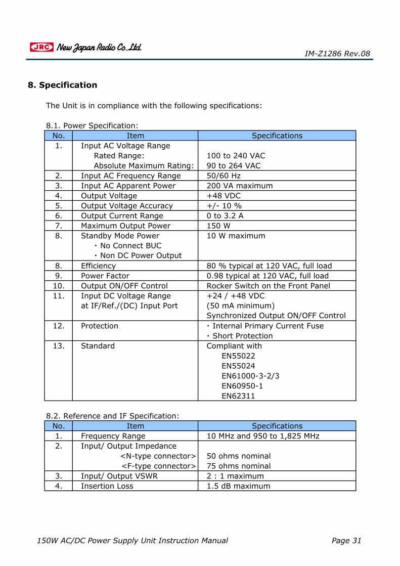
Input AC Apparent Power
90 to 264 VAC100 to 240 VAC
50/60 Hz
Input AC Voltage Range
200 VA maximum
Absolute Maximum Rating:Input AC Frequency Range
2 : 1 maximumInput/ Output VSWR
5.4.3.2.
+48 VDC+/- 10 %
Output VoltageOutput Voltage Accuracy
9.
8. Specification
Output Current RangeMaximum Output Power
10 W maximum
6.7.
8.
Specifications
EN62311 EN60950-1
Protection
EfficiencyPower FactorOutput ON/OFF Control
EN61000-3-2/3
No. Item
1.5 dB maximum
Compliant with
10 MHz and 950 to 1,825 MHz
EN55022 EN55024
8.2. Reference and IF Specification:
12.
Frequency Range1.
80 % typical at 120 VAC, full load0.98 typical at 120 VAC, full load
・ Short Protection・ Internal Primary Current Fuse
50 ohms nominal75 ohms nominal<F-type connector>
<N-type connector>
3.4.
2.
Insertion Loss
Input/ Output Impedance
13.
11.
Item
IM-Z1286 Rev.08
Standard
8.
Input DC Voltage Rangeat IF/Ref./(DC) Input Port
+24 / +48 VDC(50 mA minimum)Synchronized Output ON/OFF Control
Rocker Switch on the Front Panel
Rated Range:1.
10.
Standby Mode Power ・ No Connect BUC ・ Non DC Power Output
0 to 3.2 A150 W
No.8.1. Power Specification:
The Unit is in compliance with the following specifications:
Specifications
150W AC/DC Power Supply Unit Instruction Manual Page 32
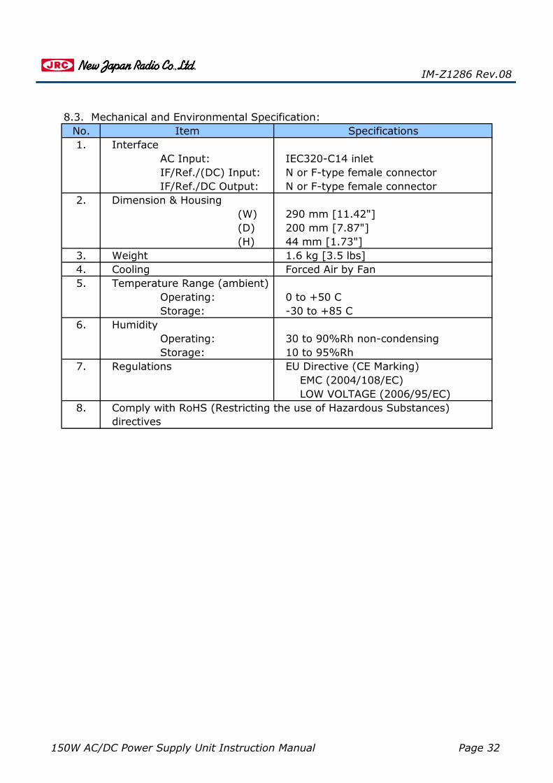
Dimension & Housing
IF/Ref./(DC) Input: IF/Ref./DC Output:
N or F-type female connectorN or F-type female connector
1.
4. Cooling Forced Air by Fan
(W) (D) (H)
3. 1.6 kg [3.5 lbs]
2.290 mm [11.42"]
IEC320-C14 inlet
IM-Z1286 Rev.08
AC Input:
SpecificationsInterface
8.3. Mechanical and Environmental Specification:No. Item
5. Temperature Range (ambient)
-30 to +85 CStorage:0 to +50 COperating:
200 mm [7.87"]
8. Comply with RoHS (Restricting the use of Hazardous Substances)directives
7. Regulations EU Directive (CE Marking)
LOW VOLTAGE (2006/95/EC)
10 to 95%Rh
6. Humidity
Storage:
Weight44 mm [1.73"]
Operating:
EMC (2004/108/EC)
30 to 90%Rh non-condensing
![[MEAN WELL] 1982 (Charger) DC/AC (Inverter) 8000 (DoE ... · PDF fileAC/DC DC/DC (Converter) (Adaptor) (Charger) DC/AC (Inverter) 8000 LED ... AC AC AC GE12/18/24/30 I AC AC Plug-AU](https://static.fdocuments.us/doc/165x107/5a73363b7f8b9abb538e72a6/mean-well-1982-charger-dcac-inverter-8000-doe-a-acdc-dcdc-converter.jpg)