1500 PSI / 1.2 GPM ELECTRIC PRESSURE WASHER ......1500 PSI / 1.2 GPM ELECTRIC PRESSURE WASHER GPW...
30
1500 PSI / 1.2 GPM ELECTRIC PRESSURE WASHER GPW 1501 Read all safety rules and instructions carefully before operating this tool. www.greenworkstools.com OPERATOR’S MANUAL TOLL-FREE HELPLINE: 1-888-90WORKS (888.909.6757)
Transcript of 1500 PSI / 1.2 GPM ELECTRIC PRESSURE WASHER ......1500 PSI / 1.2 GPM ELECTRIC PRESSURE WASHER GPW...

1500 PSI / 1.2 GPM
ELECTRIC PRESSURE WASHER
GPW 1501
Read all safety rules and instructions carefully before operating this tool.
www.greenworkstools.com
OPERATOR’S MANUAL
TOLL-FREE HELPLINE: 1-888-90WORKS (888.909.6757)

EN - 2
INSTRUCTION
Imporatant Safety Instructions………………………………………………………........................................3
Specific Safety Rules………………………………………………………………........................................4-5
Symbols………………………………………………………………………………......................................6-7
Electrical………………………………………………………………………………........................................8
Know Your Pressure Washer………………………………………………………….......................................9
Packing List..............................................................................................................................................10
Assembly………………………………………………………………………………................................11-14
Operation………………………………………………………………………………................................15-19
Maintenance…………………………………………………………………………..................................20-22
Troubleshooting……………………………………………………………………….................................23-25
Warranty……………………………………………………………………………………...............................26
Exploded View…………………………………………………………………………................................….27
Parts List………………………………………………………………………………….............................28-29
PRODUCT SPECIFICATION
Universal Motor……………………………………………………….................................120V,60Hz,13Amps
Power Cord with In-Line GFCI................................................................................................................35ft
Max. Pounds Per Square Inch Pressure…………………………………….......................................1500psi
Rated Gallons Per Minute……………………………………………………….....................................1.2gpm
Maximum Inlet Water Temperature……………………………………………..…….................104°F(40℃)Cleaning Units...............................................................................................................................1800 C.U
Unit Weight……………………………………………………………......................................19.07lbs(8.64kg)

EN - 3
IMPORTANT SAFETY INTRODUCTIONS
W A R N I N G
Read and understand all instructions. Failure to follow all instructions listed below may result in electric
W A R N I N G
When using this product, basic precaution should always be followed, including the following.
READ ALL INSTRUCTIONS BEFORE USING THIS PRODUCT
Be thoroughly familiar with controls. Know how to stop the product and release pressure quickly.
Stay alert and exercise control. Watch what you are doing and use common sense. Do not operate the product when you are tired. Do not rush.
Do not operate the product while under the influence of drugs, alcohol, or any medication.
Keep the area of operation clear of all people, particularly small children, and pets.
Don’t overreach or stand on unstable support. Keep proper footing and balance at all times.
Follow the maintenance instructions specified in this manual.
W A R N I N G
GROUND FAULT CIRCUIT INTERRUPTER PROTECTION
This pressure washer is provided with a ground fault circuit interrupter (GFCI) built into the plug of the
power supply cord. This device provides additional protection from the risk of electric shock. Should
replacement of the plug or cord become necessary, use only identical replacement parts that include
GFCI protection.
SERVICING OF A DOUBLE-INSULATED APPLIANCE
In a double-insulated product, two systems of insulation are provided instead of grounding. No
grounding means is provided on a double-insulated product, nor should a means for grounding be
added to the product. Servicing a double insulated product requires extreme care and knowledge of the
system, and should be done only by qualified service personnel. Replacement parts for a double
insulated product must be identical to the parts they replace. A double insulated product is marked with
the words “DOUBLE INSULATION” or “DOUBLE INSULATED.”The symbol may also be marked on
the product.
EXTENSION CORDS
Do not use with extension cord. Plug directly into receptacle.
W A R N I N G
To reduce the risk of electrocution, keep all connections dry and off the ground. Do not touch plug with
wet hands.

EN - 4
SPECIFIC SAFETY RULES
Know your product. Read the operator’s manual carefully. Learn the machine’s applications and limitations as well as the specific potential hazards related to this product.
To reduce the risk of injury, keep children and visitors away. All visitors should wear safety glasses and be kept a safe distance from the work area.
Use the right product for the job.designed for. Don’t use it for a purpose not intended.
Dress properly.draw you into moving parts. Rubber gloves and nonskid footwear are recommended when working outdoors. Also wear protective hair covering to contain long hair.
Do not operate the equipment while barefoot or when wearing sandals or similar lightweight footwear. Wear protective footwear that will protect your feet and improve your footing on slippery surfaces.
Exercise caution to avoid slipping or falling.
Always wear eye protection with side shields marked to comply with ANSI Z87.1. Following
Use only recommended accessories.
Check damaged parts. Before further use of the product, all parts should be carefully checked to determine that they will operate properly and perform their intended function. Check for alignment of moving parts, binding of moving parts, breakage of parts, mounting, and any other conditions that may affect its operation. A guard or other part that is damaged must be properly repaired or replaced
Never leave product running unattended. Turn power off. Do not leave the product until it comes to a complete stop.
Keep the motor free of grass, leaves, or grease to reduce the chance of a fire hazard.
Follow manufacturer’s recommendations for safe loading, unloading, transport, and storage of machine.
Keep product dry, clean, and free from oil and grease. Always use a clean cloth when cleaning. Never use brake fluids, gasoline, petroleum-based products, or any solvents to clean product.
Check the work area before each use.or string which can be thrown by the machine.
Do not use product if switch does not turn it off. Have defective switches replaced by an authorized service center.
Avoid dangerous environment. Don’t expose to rain. Keep work area well lit.
Do not abuse the cord. Never use the cord to carry the product or to disconnect the plug from an outlet. Keep cord away from heat, oil, sharp edges, or moving parts. Replace damaged cords immediately. Damaged cords increase the risk of electric shock.
Ground Fault Circuit Interrupter (GFCI) protection should be provided on the circuit(s) or outlet(s) to be used for the product Receptacles are available having built-in GFCI protection and may be used for this measure of safety.
To reduce the risk of electric shock, this product has a polarized plug (one blade is wider than the other) and will require the use of a polarized extension cord. The plug will fit into a polarized extension cord only one way. If the plug does not fit fully into the extension cord, reverse the plug. If the plug still does not fit, obtain a correct polarized extension cord. A polarized extension cord will require the use of a polarized wall outlet. This plug will fit into the polarized wall outlet only one way. If the plug does not fit fully into the wall outlet, reverse the plug. If the plug still does not fit, contact a qualified electrician to install the proper wall outlet. Do not change the equipment plug, extension cord receptacle, or extension cord plug in any way.

EN - 5
SPECIFIC SAFETY RULES
Make sure your extension cord is in good condition. When using an extension cord, be sure to use one heavy enough to carry the current your product will draw. A wire gauge size (A.W.G.) of at least 14 is recommended for an extension cord 25 feet or less in length. If in doubt, use the next heavier gauge. The smaller the gauge number, the heavier the cord. An undersized cord will cause a drop in line voltage resulting in loss of power and overheating.
Inspect extension cords periodically and replace if damaged. Keep handles dry, clean, and free from oil or grease.
Never direct a water stream toward people or pets, or any electrical device.
Before starting any cleaning operation, close doors and windows. Clear the area to be cleaned
Do not use acids, alkalines, solvents, flammable material, bleaches, or industrial grade solutions in this product. irreversible damage to the machine.
W A R N I N G
High pressure jets can be dangerous if subject to misuse.
animals, electrical devices, or the machine itself.
Keep the motor away from flammables and other hazardous materials.
Check bolts and nuts fixing the pressure washer shell for looseness before each use. A loose bolt or nut may cause serious motor problems.
Before storing, allow the motor to cool.
When servicing use only identical replacement parts. Use of any other parts may create a hazard or cause product damage.
ONLY use cold water.
Make sure minimum clearance of 3 feet is maintained from combustible materials.
Connect pressure washer only to an individual branch circuit.
Hold the handle and wand securely with both hands. Expect the trigger handle to move when
yourself and others.
Save these instructions. Refer to them frequently and use them to instruct other users. If you loan someone this product, loan them these instructions also.
W A R N I N G
Some dust created by power sanding, sawing, grinding, drilling, and other construction activities
contains chemicals known to cause cancer, birth defects or other reproductive harm. Some examples of
these chemicals are:
Your risk from these exposures varies, depending on how often you do this type of work. To reduce your
exposure to these chemicals: work in a well ventilated area, and work with approved safety equipment,
.
W A R N I N G
This product contains chemical(s) including lead, known to the State of California to cause cancer, birth
defects, and other reproductive harm. Do not drink water from this hose. Wash hands after use.
EN - 6
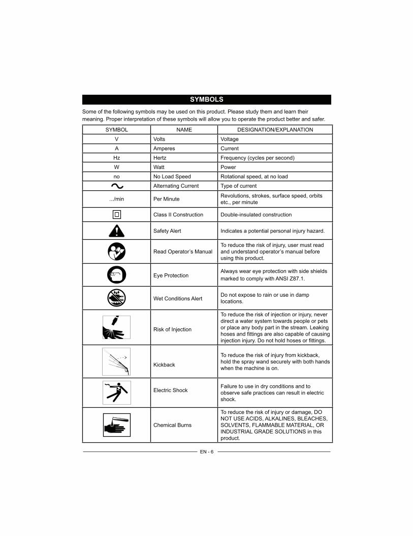
SYMBOLS
Some of the following symbols may be used on this product. Please study them and learn their
meaning. Proper interpretation of these symbols will allow you to operate the product better and safer.
SYMBOL NAME
V Volts Voltage
A Amperes Current
Hz Hertz Frequency (cycles per second)
W Watt Power
no No Load Speed Rotational speed, at no load
Alternating Current Type of current
Per MinuteRevolutions, strokes, surface speed, orbits
etc., per minute
Class II Construction Double-insulated construction
Safety Alert
Read Operator’s Manual and understand operator’s manual before
using this product.
Eye ProtectionAlways wear eye protection with side shields
marked to comply with ANSI Z87.1.
Wet Conditions AlertDo not expose to rain or use in damp
locations.
direct a water system towards people or pets
or place any body part in the stream. Leaking
hoses and fittings are also capable of causing
Kickbackhold the spray wand securely with both hands
when the machine is on.
Electric ShockFailure to use in dry conditions and to
observe safe practices can result in electric
shock.
Chemical Burns
NOT USE ACIDS, ALKALINES, BLEACHES,
SOLVENTS, FLAMMABLE MATERIAL, OR
INDUSTRIAL GRADE SOLUTIONS in this
product.
EN - 7
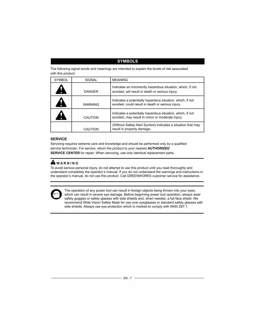
SYMBOLS
The following signal words and meanings are intended to explain the levels of risk associated
with this product.
SYMBOL SIGNAL MEANING
DANGER
Indicates an imminently hazardous situation, which, if not
WARNING
Indicates a potentially hazardous situation, which, if not
CAUTION
Indicates a potentially hazardous situation, which, if not
CAUTION
(Without Safety Alert Symbol) Indicates a situation that may
result in property damage.
SERVICE
service technician. For service, return the product to your nearest AUTHORIZED
SERVICE CENTER for repair. When servicing, use only identical replacement parts.
W A R N I N G
understand completely the operator’s manual. If you do not understand the warnings and instructions in
the operator’s manual, do not use this product. Call GREENWORKS customer service for assistance.
which can result in severe eye damage. Before beginning power tool operation, always wear
safety goggles or safety glasses with side shields and, when needed, a full face shield. We
recommend Wide Vision Safety Mask for use over eyeglasses or standard safety glasses with
side shields. Always use eye protection which is marked to comply with ANSI Z87.1.
EN - 8
ELECTRICAL
W A R N I N G
The double insulated system is intended to protect the user from shock resulting from a break in the
product’s internal insulation. Observe all normal safety precautions to avoid electrical shock.
DOUBLE INSULATED
Double insulation is a concept in safety in electric power tools, which eliminates the need for the usual
three-wire grounded power cord. All exposed metal parts are isolated from the internal metal motor
components with protecting insulation. Double insulated products do not need to be grounded.
NOTE: Servicing of a product with double insulation requires extreme care and knowledge of the
system and should be performed only by a qualified service technician. For service, we suggest you
return the product to your nearest authorized service center for repair. Always use identical replacement
parts when servicing.
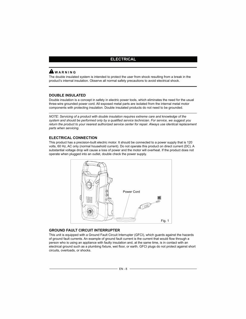
ELECTRICAL CONNECTION
This product has a precision-built electric motor. It should be connected to a power supply that is 120
volts, 60 Hz, AC only (normal household current). Do not operate this product on direct current (DC). A
substantial voltage drop will cause a loss of power and the motor will overheat. If the product does not
operate when plugged into an outlet, double check the power supply.
GROUND FAULT CIRCUIT INTERRUPTER
This unit is equipped with a Ground Fault Circuit Interrupter (GFCI), which guards against the hazards
person who is using an appliance with faulty insulation and, at the same time, is in contact with an
circuits, overloads, or shocks.
Fig. 1
Power Cord

EN - 9
KNOW YOUR PRESSURE WASHER
The safe use of this product requires an understanding of the information on the tool and in this
familiarize yourself with all operating features and safety rules. (See Figure 2.)
DETERGENT TANK
Remove the cap from the detergent tank to add detergent to the pressure washer.
GFCI PLUG
The pressure washer is equipped with a GFCI plug to guard against the hazards of ground fault
currents. This plug does not protect against short circuits, overloads, or shocks.
HIGH PRESSURE HOSE STORAGE
Once the high pressure hose is rolled, hang it on the top of the machine using the hook-and-loop strap
to secure in place.
ON / OFF SWITCH
This switch turns the pressure washer on and off.
TRIGGER HANDLE
The trigger handle has a gripping surface that provides added control of the spray wand and helps
reduce fatigue.
TRIGGER WITH LOCK-OUT
Pulling the trigger releases a stream of water for high pressure cleaning. The lock-out provides
protection against accidental start up.
WATER INTAKE
Attach the garden hose to the water intake.
WATER OUTLET
Attach the High Pressure Hose to the water outlet.
Trigger with Lock-out
Handle
GFCI
High Pressure Hose
Water Outlet
Trigger Handle
Fig. 2
Detergent Tank
Spray Tips Water Intake

EN - 10
PACKING LIST
PART NAME ERP NO. FIGURE QTY
(including the spray tip)1
312021639 1
312011639 1
31203670 1
31111368 1
Spray Cleaner 33201671 1
388021639
Missing parts, accessories or need a service center?
Do Not Return to StoreCall : 1-888-909-6757
www.GreenWorksTools.com
Rev:01
INSTALLING DETERGENT BOTTLE
Insert the male end of the bottle into the female outlet on the trigger handle.
While pushing in the bottle firmly, turn clockwise until tabs lock into place to ensure a leak-free connection.
Unscrew the bottle from the assembly and fill with pressure
SPRAY TIP SPRAY TIP APPLICATION
25O
Green - Narrow fan tip (25° ) The green pressure washer tip provides high versatility with its 25 degree angle tip. Referred to as the washing tip, because it
provides adequate pressure to remove dirt from surfaces, but is designed to not damage many surfaces. This pressure washer tip is
designed for “sweeping” foliage or debris given its wide angle. This tip is versatile due to its wide area of cleaning and strong pressure
application.
40O
White - Wide fan tip (40° ) The white 40 degree tip, referred to as the “fan” tip creates the widest area of cleaning with relatively low pressure. This pressure
washer tip is best used for light or delicate cleaning applications. It is recommended for light cleaning on wood decks and other soft or
delicate surfaces.
Connect garden hose to pressurewasher water intake.
Assemble pressure washer gun t o spray wand.
Insert h igh pressure hose into t rigge r handle.
Turn on water at outlet.
Run water hose for 120 seconds with the motor in OFF position. This helps drain air
from the tank and lines.
Connect power cord to wall outletExtension cord not recommended.
Turn on Pressure WasherIMPORTANT: Ensure water outlet is On
before turning power On to avoid damageto the pump.
NOTE:
AUTO ON/OFF SWITCH: This Pressure washer is equippedwith an Auto Start/Stop feature.
To operate: Turn the power switch to the On (I) position. Pump will pressurize and shut down immediately.
Once the trigger of the gun is depressed the unit will turn on.Unit will shut off and be in standby mode when trigger is released.
1501 PSI / 1.2 GPMELECTRIC PRESSURE WASHER
GPW 1501
This Quick Start Guide is not a substitute for reading the operator's manual. To reduce the riskof injury or death, user must read and understand operator's manual before using this product.
WARNING: Set-up Slide the handle into the slots until it locks into place.
Insert the screws into the holes and tighten the screws with a phillips head
screwdriver (not included).
1
2
3
Pull back the quick-connect collar
Push the spray tip into place
Push the collar forward
CONNECTING DESIRED SPRAY TIP
Insert high pressure hose into the pressure washer.
1
4
5
8
2
Screws
3
7
120S
6 1
388011639 1
40°Spray Tip 25°Spray Tip
1501 P
SI / 1.2
GP
M
EL
EC
TR
IC P
RE
SS
UR
E W
AS
HE
R
GP
W 1
501
R
ead a
ll safe
ty r
ule
s a
nd instr
uctions c
are
fully
befo
re o
pera
ting this
tool.
ww
w.g
reenw
ork
sto
ols
.com
OP
ER
ATO
R’S
MA
NU
AL
TO
LL
-FR
EE
HE
LP
LIN
E:
1-8
88-9
0W
OR
KS
(888.9
09.6
757)

EN - 11
ASSEMBLY
UNPACKING
This product requires assembly.
Carefully remove the product and any accessories from the box. Make sure that all the contents from the packaging list are included.
W A R N I N G
Do not use this product if any parts on the Packing List are already assembled to your product when you
unpack it. Parts on this list are not assembled to the product by the manufacturer and require customer
installation. Use of a product that may have been improperly assembled could result in serious personal
Inspect the product carefully to make sure no breakage or damage occurred during shipping.
Do not discard the packing material until you have carefully inspected and satisfactorily operated the product.
If any parts are damaged or missing, please call 1-888-909-6757 for assistance.
W A R N I N G
If any parts are damaged or missing do not operate this product until the parts are replaced. Use of this
W A R N I N G
Do not connect to power supply until assembly is complete. Failure to comply could result in accidental
W A R N I N G
Do not attempt to modify this product or create accessories not recommended for use with this product.
Any such alteration or modification is misuse and could result in a harzardous condition leading to

EN - 12
ASSEMBLY
ASSEMBLING THE PRESSURE WASHER GUN
Insert the male end (A) of the wand into the female bayonet outlet (B) firmly. (See Figure 3-1.)
While pushing in the wand firmly, turn clockwise until tabs lock into place to ensure a leak-free connection. (See Figure 3-2.)
CONNECTING HIGH PRESSURE HOSE TO TRIGGER HANDLE (See Figure 4.)
Connect the high pressure hose to the pressure washer gun assembly by turning the fitting clockwise. Ensure the fitting is fully tightened to the pressure washer gun.
NOTE: For easier installation of the hose to the unit or trigger it is suggested to add pressure washer or dish detergent to the rubber seal at each end of the hose. This will allow for easier installation and a snug fit.
AB
Fig. 3-1 Fig. 3-2
High Pressure Hose
Collar
Fig. 4
Inlet Coupler

EN - 13
ASSEMBLY
DETERGENT TANK
Insert the male end of the bottle into the female outlet on the trigger handle. (See Figure 5-1.)
While pushing in the bottle firmly, turn clockwise until tabs lock into place to ensure a leak-free connection. (See Figure 5-2.)
Fig. 5-2 Fig. 5-1

EN - 14
ASSEMBLY
CONNECTING THE GARDEN HOSE (See Figure 6.)
C A U T I O N :
Always observe all local regulations when connecting hoses to the water main. Some areas have
restrictions against connecting directly to public drinking water supply to prevent the feedback of
preventer is usually permitted.
The water supply must come from a water main. NEVER use hot water or water from pools, lakes, etc.
Before connecting the garden hose:
Uncoil the garden hose.
Run the water hose until a steady stream of water appears to clean any debris from the hose.
Inspect the screen in the water intake for any damage or build up of debris.
If the screen is damaged, do not use the machine until the screen has been replaced.
If the screen is dirty, clean it before connecting the garden hose to the machine.
With the hose faucet turned completely off, attach the end of the garden hose to the water intake. Tighten by hand.
W A R N I N G
Always ensure that the garden hose is connected to the unit and that the faucet is turned on, before the
power to the unit is switched on. Pump damage will occur if these steps are not followed.
Fig. 6

EN - 15
OPERATION
W A R N I N G
Do not allow familiarity with the product to make you careless. Remember that a careless fraction of a
W A R N I N G
Never direct a water stream toward people or pets, or any electrical device. Failure to heed this warning
APPLICATIONS
You may use this product for the purposes listed below:
Cleaning cars, boats, motorcycles, outdoor furniture, grills, and house siding.
ADDING DETERGENT TO THE PRESSURE WASHER (See Figure 7.)
Use only detergents designed for pressure washers; household detergents, acids, alkalines, bleached,
Many detergents may require mixing prior to use. Prepare cleaning solution as instructed on the
solution bottle.
- Unscrew the bottle from the soap applicator.
- Place the bottle on the ground or other stable surface.
- Fill with pressure washer detergent.
- Screw the bottle back onto the soap applicator.
- Attach the soap applicator to the trigger handle
NOTE: Use a funnel, if needed, to prevent accidental spilling of the detergent outside the tank. If
proceeding.
Fig.7

EN - 16
OPERATION
STARTING AND STOPPING THE PRESSURE WASHER
C A U T I O N :
Do not run the pump without the water supply connected and turned on.
Connect the garden hose.
Turn the garden hose on then squeeze the high pressure trigger to relieve air pressure. Once a steady stream of water appears, release the trigger.
supply.
Plug the pressure washer into the outlet and ensure the light on the GFCI is on, the unit is ready for operation.
W A R N I N G
Hold the handle and wand securely with both hands. Expect the trigger handle to move when the trigger
others.
NOTE: AUTO ON/OFF SWITCH: This Pressure washer is equipped with an Auto Start/Stop feature.
To operate: Turn the power switch to the On (I) position. Pump will pressurize and shut down
immediately. Once the trigger of the gun is depressed the unit will turn on. Unit will shut off and be in
standby mode when trigger is released.
SOAP APPLICATION
Soap is applied under low pressure high volume for optimum performance.
Soap can not be applied under high pressure with this machine

EN - 17
OPERATION
USING THE SPRAY WAND TRIGGER
For greater control and safety, keep both hands on the pressure washer gun at all times.
TO ENGAGE THE LOCK-OUT (See Figure 8-1.)
Push up on the lock-out until it clicks into the slot. This will prevent any unintentional starts of the pressure washer.
TO DISENGAGE THE LOCK-OUT (See Figure 8-2.)
Push the lock-out down and into its original position. For the most effective cleaning, the spray tip should be between 8 in. and 24 in. from the surface to be cleaned. If the spray is too close it can damage the cleaning surface.
W A R N I N G
Do not slide lock-out button when you have the trigger at back position.
Fig. 8-1 Fig. 8-2
LockedUnlocked

EN - 18
OPERATION
CHANGING THE SPRAY TIP (See Figure 9.)
W A R N I N G
NEVER change spray tips without engaging the lock-out on the trigger handle and NEVER point the
Turn off the pressure washer and shut off the water supply. Pull trigger to release water pressure.
Engage the lock-out on the trigger handle by pushing the trigger lock button to the right.
Pull back the quick-connect collar on the spray wand.
Push the spray tip into place in the spray wand.
Push the collar forward so that the spray tip is secured properly. Check to see that the spray tip is secure.
SPRAY TIP APPLICATION
25O
Green - Narrow fan tip (25° )
The green pressure washer tip provides high versatility with its 25 degree angle tip. Referred to as the washing tip, because it provides adequate pressure to remove dirt from surfaces, but is designed to not damage many surfaces. This pressure washer tip is designed for “sweeping” foliage or debris given its wide angle. This tip is versatile due to its wide area of cleaning and strong pressure application.
40O
White - Wide fan tip (40° )
The white 40 degree tip, referred to as the “fan” tip creates the widest area of cleaning with relatively low pressure. This pressure washer tip is best used for light or delicate cleaning applications. It is recommended for light cleaning on wood decks and other soft or delicate surfaces.
Fig. 9
1
2
3
Spray Tip
Spray Wand
1-Pull back the quick-connect collar
2-Push the spray tip into place
3-Push the collar forward

EN - 19
OPERATION
OPERATING THE PRESSURE WASHER (See Figure 10.)
Use only detergents designed for pressure washers.
Soap is applied under low pressure high volume for optimum performance.
Soap can not be applied under high pressure with this machine.
To clean:
Install the soap attachment on the spray wand.
Start the pressure washer and spray the detergent on a dry surface using long, even, overlapping strokes. To prevent streaking, do not allow detergent to dry on the surface.
To rinse:
Using the desired tip, spray away from the rinsing surface for approximately 10 seconds to allow any remaining detergent to be flushed from the line.
Start at the top of the area to be rinsed and work down, overlapping the strokes.
MOVING THE PRESSURE WASHER
To move the pressure washer:
Turn the pressure washer off. Point the spray wand in a safe direction and pull trigger to release water pressure.
Tilt the machine toward you until it balances on the wheels then roll the machine to the desired position.
Fig. 10

EN - 20
MAINTENANCE
W A R N I N G
When servicing, use only identical replacement parts. Use of any other parts may create a hazard or
cause product damage.
W A R N I N G
Before inspecting, cleaning or servicing the machine,turn off the unit, unplug from the outlet, pull trigger
to release water pressure and disconnect the high pressure hose. Failure to follow these instructions
GENERAL MAINTENANCE
Avoid using solvents when cleaning plastic parts. Most plastics are susceptible to damage from various
types of commercial solvents and may be damaged by their use. Use clean cloths to remove dirt, dust,
oil, grease, etc.
W A R N I N G
in contact with plastic parts. Chemicals can damage, weaken or destroy plastic which may result in
Only the parts shown on the parts list are intended to be repaired or replaced by the customer.
All other parts should be replaced at an authorized service center.
EN - 21
MAINTENANCE
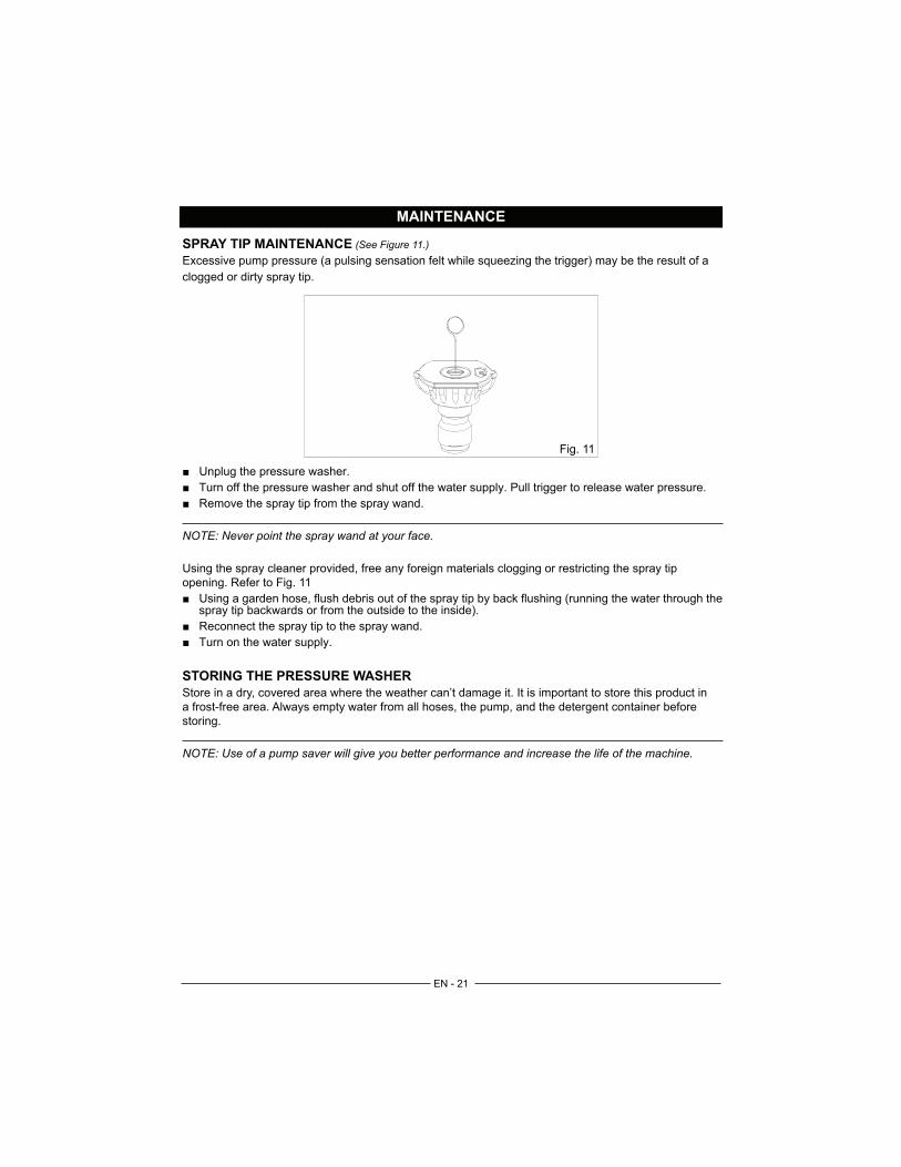
SPRAY TIP MAINTENANCE (See Figure 11.)
Excessive pump pressure (a pulsing sensation felt while squeezing the trigger) may be the result of a
clogged or dirty spray tip.
Unplug the pressure washer.
Turn off the pressure washer and shut off the water supply. Pull trigger to release water pressure.
Remove the spray tip from the spray wand.
NOTE: Never point the spray wand at your face.
Using the spray cleaner provided, free any foreign materials clogging or restricting the spray tip
opening. Refer to Fig. 11
Using a garden hose, flush debris out of the spray tip by back flushing (running the water through the spray tip backwards or from the outside to the inside).
Reconnect the spray tip to the spray wand.
Turn on the water supply.
STORING THE PRESSURE WASHER
Store in a dry, covered area where the weather can’t damage it. It is important to store this product in
a frost-free area. Always empty water from all hoses, the pump, and the detergent container before
storing.
NOTE: Use of a pump saver will give you better performance and increase the life of the machine.
Fig. 11
EN - 22
MAINTENANCE
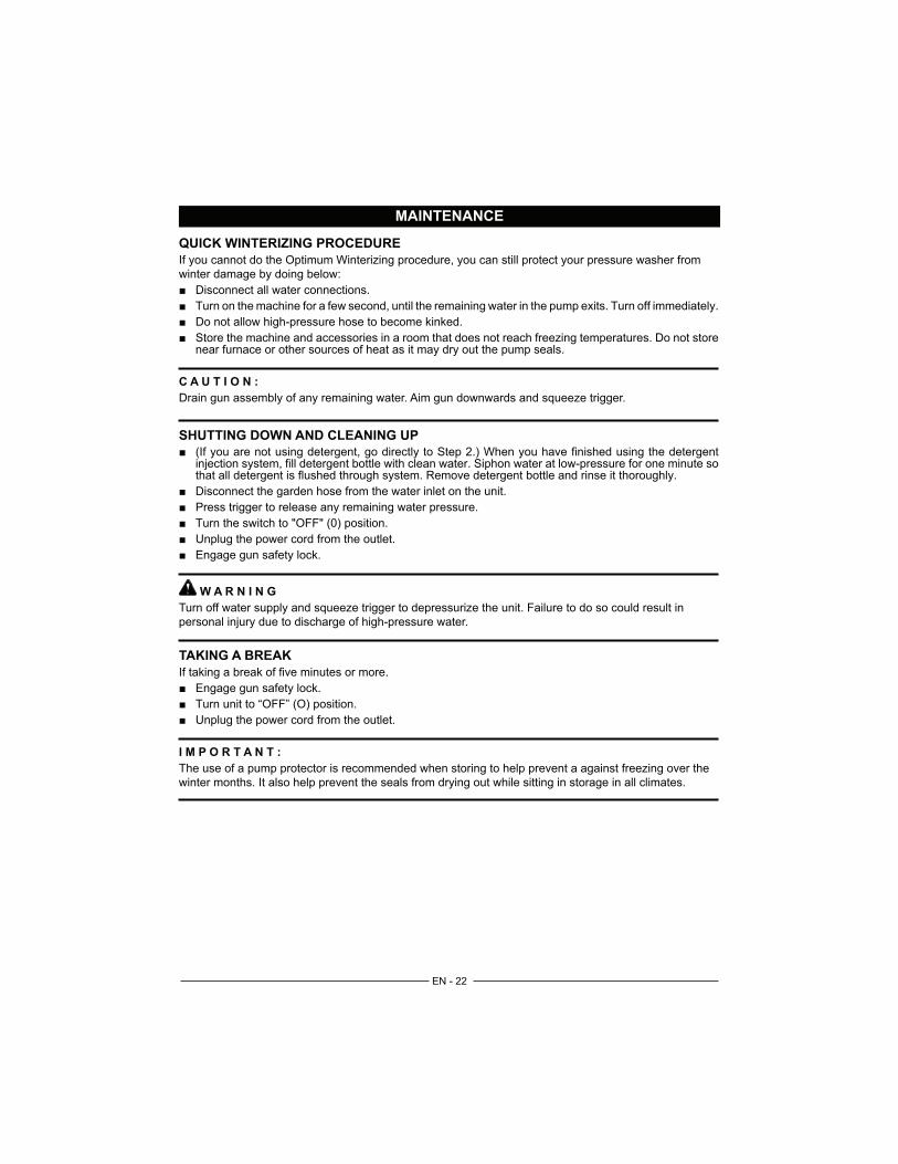
QUICK WINTERIZING PROCEDURE
If you cannot do the Optimum Winterizing procedure, you can still protect your pressure washer from
winter damage by doing below:
Disconnect all water connections.
Turn on the machine for a few second, until the remaining water in the pump exits. Turn off immediately.
Do not allow high-pressure hose to become kinked.
Store the machine and accessories in a room that does not reach freezing temperatures. Do not store near furnace or other sources of heat as it may dry out the pump seals.
C A U T I O N :
Drain gun assembly of any remaining water. Aim gun downwards and squeeze trigger.
SHUTTING DOWN AND CLEANING UP
(If you are not using detergent, go directly to Step 2.) When you have finished using the detergent
that all detergent is flushed through system. Remove detergent bottle and rinse it thoroughly.
Disconnect the garden hose from the water inlet on the unit.
Press trigger to release any remaining water pressure.
Unplug the power cord from the outlet.
Engage gun safety lock.
W A R N I N G
Turn off water supply and squeeze trigger to depressurize the unit. Failure to do so could result in
TAKING A BREAK
Engage gun safety lock.
Turn unit to “OFF” (O) position.
Unplug the power cord from the outlet.
I M P O R T A N T :
The use of a pump protector is recommended when storing to help prevent a against freezing over the
winter months. It also help prevent the seals from drying out while sitting in storage in all climates.
EN - 23
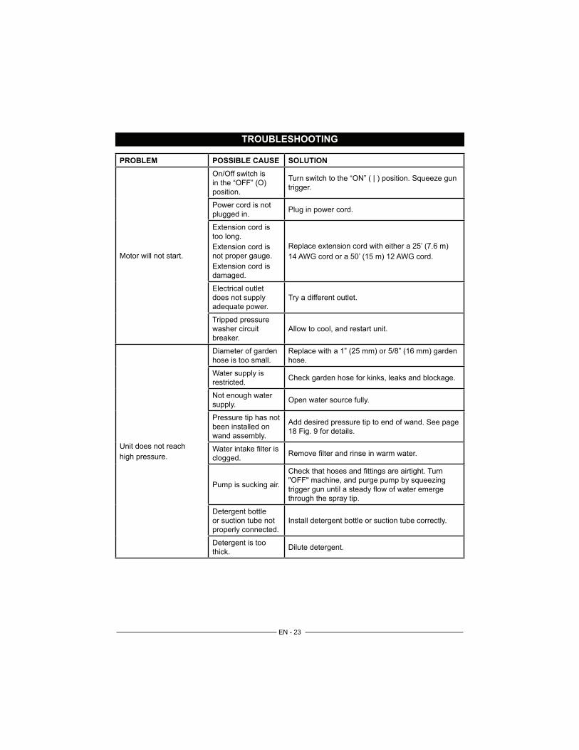
TROUBLESHOOTING
PROBLEM POSSIBLE CAUSE SOLUTION
Motor will not start.
in the “OFF” (O)
position.
Turn switch to the “ON” ( | ) position. Squeeze gun
trigger.
Power cord is not
plugged in.Plug in power cord.
Extension cord is
too long.
Extension cord is
not proper gauge.
Extension cord is
damaged.
Replace extension cord with either a 25’ (7.6 m)
14 AWG cord or a 50’ (15 m) 12 AWG cord.
Electrical outlet
does not supply
adequate power.
Try a different outlet.
Tripped pressure
washer circuit
breaker.
Allow to cool, and restart unit.
Unit does not reach
high pressure.
Diameter of garden
hose is too small. hose.
Water supply is
restricted.Check garden hose for kinks, leaks and blockage.
Not enough water
supply.Open water source fully.
Pressure tip has not
been installed on
wand assembly.
Add desired pressure tip to end of wand. See page
18 Fig. 9 for details.
Water intake filter is
clogged.
Pump is sucking air.
through the spray tip.
Detergent bottle
or suction tube not
properly connected.
Install detergent bottle or suction tube correctly.
Detergent is too
thick.Dilute detergent.

EN - 24
TROUBLESHOOTING
PROBLEM POSSIBLE CAUSE SOLUTION
Unit does not reach
high pressure.
(continued)
Filter on detergent
suction tube is
clogged.
Run warm water through the filter to remove build
up.
Damaged or clogged
detergent suction
tube.
Remove obstruction or replace detergent suction
tube.
Discharge spray tip is
obstructed.
Blow out or remove debris with a needle or spray
cleaner. Refer to Fig. 11 in this manual.
Output pressure varies
high and low.
Not enough inlet
water supply.
Turn water on fully. Check garden hose for kinks,
leaks or blockage.
Pump is sucking air.
through the spray tip.
Water intake filter
clogged.
Discharge spray tip is
obstructed.
Blow out or remove debris with a needle or spray
cleaner. Refer to Fig. 11 in this manual.
power spray tip.
Clean with distilled vinegar or a cleaner specifically
made for the task.
Garden hose
connection leaks.
Loose fittings.
washer.Replace washer.
Spray wand, extension,
or spray tip leaks.
Broken o-ring or
plastic insert.Call the Toll-Free Helpline.
Pump is noisy.
Pump is sucking air.
through the spray tip.
Water inlet filter
clogged.
Water leaks from
pump.
Loose fittings. Check that all fittings are tight.
Water seals are
damaged or worn.Call the Toll-Free Helpline.
Oil is dripping. Oil seals are
damaged or worn.Call the Toll-Free Helpline.

EN - 25
TROUBLESHOOTING
PROBLEM POSSIBLE CAUSE SOLUTION
Motor buzzes but fails
to run.
Supply voltage below
minimum.
Verify that only the pressure washer is running on
this circuit.
System has residual
pressure.
Turn unit “OFF”, squeeze trigger on spray wand to
release pressure, then turn unit “ON”.
Voltage loss due to
extension cord.
Unplug any extension cords attached and plug the
unit directly into the outlet.
Pressure washer not
used for long periods.Call the Toll-Free Helpline.
Residual friction
among components.
Unit might hum.
Disconnect water supply and power ON for 2 to
3 seconds, repeat couple times or until the motor
starts.
No water.
Water supply is OFF. Turn ON water supply.
Kink in the garden
hose.Remove kink in garden hose.
NOTE: AUTO ON/OFF SWITCH: This Pressure washer is equipped with an Auto Start/
Stop feature. To operate: Press power switch On (I). Pump will pressurize and shut
down immediately. Once the trigger of the gun is depressed the unit will turn on. Unit
will shut off and be in standby mode when trigger is released.

EN - 26
WARRANTY
GREENWORKS™ hereby warranties this product, to the original purchaser with proof of purchase, for a
period of one (1) years against defects in materials, parts or workmanship. GREENWORKS™, at its own
discretion will repair or replace any and all parts found to be defective, through normal use, free of charge
to the customer. This warranty is valid only for units which have been used for personal use that have not
the instructions in the owners’ manual supplied with the product from new.
ITEMS NOT COVERED BY WARRANTY:
1. Any part that has become inoperative due to misuse, commercial use, abuse, neglect, accident,
improper maintenance, or alteration; or
3. Normal wear, except as noted below;
pump and components.
GREENWORKS HELPLINE (1-888-90WORKS):
Warranty service is available by calling our toll-free helpline, at 1-888-909-6757 (1-888-90WORKS).
Order Replacement parts online @ www.greenworkstools.com
TRANSPORTATION CHARGES:
Transportation charges for the movement of any power equipment unit or attachment are the responsibility
of the purchaser. It is the purchaser’s responsibility to pay transportation charges for any part submitted
for replacement under this warranty unless such return is requested in writing by GREENWORKS.

EN - 27
EXPLODED VIEW

EN - 28
PARTS LIST
ITEM NO. PART NO. DESCRIPTION QTY
1 341091639 Switch knob 1
2 341041639 Performance label panel 1
3 341031639 Front panel 1
4 341011639 Front housing 1
5 311161639 Switch box cover assy 1
6 363021628 Power switch 1
7 311151639 Motor & pump assy 1
8 32202847 Screw ST4.2*15-F 2
9 3410801 Power cord clamp 1
10 34222302 Power cord grommet 1
11 34211319 Nozzle grommet 2
12 31225363 25 degree spray tip 1
13 31240363 40 degree spray tip 1
14 311021828 Power cord assy 1
15 341021639 Back housing 1
16 32202847 Screw ST4.2*15-F 9
17 311041828 Handle assy 1
18 311131639 Back upper panel assy 1
19 341061639 Back lower panel assy 1
20 341021828 Left wheel axle hole cover 1
21 341031828 Right wheel axle hole cover 1
22 311141639 Water inlet pipe assy 1
23 34213301A O-ring 1
24 33177307 Water inlet nut 1
EN - 29
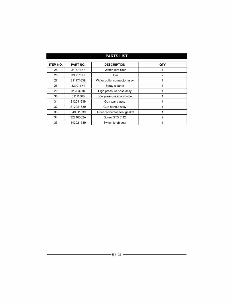
PARTS LIST
ITEM NO. PART NO. DESCRIPTION QTY
25 31901677 Water inlet filter 1
26 33307671 Upin 2
27 311171639 Water outlet connector assy 1
28 33201671 Spray cleaner 1
29 31203670 High pressure hose assy 1
30 31111368 Low pressure soap bottle 1
31 312011639 Gun wand assy 1
32 312021639 Gun handle assy 1
33 349011639 Outlet connector seal gasket 1
34 32210302A Screw ST3.5*12 2
35 342021639 Switch knob seal 1

TOLL-FREE HELPLINE: 1-888-90WORKS (888.909.6757)
Rev: 00 (14-12-09)