150 A TIG WELDING MACHINE - Systematics Inc. · 032011 150 A TIG WELDING MACHINE TIG150i...
23
032011 150 A TIG WELDING MACHINE TIG150i INTRODUCTION The TIG150i is a 150A inverter-style AC/DC TIG welder that is used to weld both ferrous and non-ferrous metals. The inverter technology is a smaller and therefore lighter package size allows portability when needed or can also be placed onto a cart for traditional use around the shop. Welding capabilities range from extremely thin up to 1/4” on multiple passes. The welder features ease-of-use for quick start-up in addition to multiple features such as upslope, downslope, pulse and frequency adjustment or the most experienced welder. Applications include automotive repair, collision repair, motorsports, manufacturing, marine, aviation, agriculture and metal fabrication shops.
Transcript of 150 A TIG WELDING MACHINE - Systematics Inc. · 032011 150 A TIG WELDING MACHINE TIG150i...

032011
150 A TIG WELDING MACHINE TIG150i
INTRODUCTION
The TIG150i is a 150A inverter-style AC/DC TIG welder that is used to weld both ferrous and non-ferrous metals. The inverter technology is a smaller and therefore lighter package size allows portability when needed or can also be placed onto a cart for traditional use around the shop. Welding capabilities range from extremely thin up to 1/4” on multiple passes. The welder features ease-of-use for quick start-up in addition to multiple features such as upslope, downslope, pulse and frequency adjustment or the most experienced welder. Applications include automotive repair, collision repair, motorsports, manufacturing, marine, aviation, agriculture and metal fabrication shops.

1
Introduction............................................................................................................................... Front Cover
Table of Contents ...................................................................................................................................... 1
Safety Information ..................................................................................................................................2-3
Specifications ............................................................................................................................................ 4
Features .................................................................................................................................................... 5
Description of Equipment .......................................................................................................................6-9
Assembling the Unit/Start-up Guide ........................................................................................................ 10
TIG Welding – Introduction.................................................................................................................11-12 - DC TIG Welding............................................................................................................................ 13 - AC TIG Welding.......................................................................................................................14-15 - Optional Foot/Remote Amperage Control .................................................................................... 16
Stick Arc Welding .................................................................................................................................... 17
Troubleshooting/Maintenance ................................................................................................................. 18
Replacement Parts .............................................................................................................................19-20 - Parts List ....................................................................................................................................... 19 - Standard and Optional Accessories ............................................................................................. 20
Wiring Diagram........................................................................................................................................ 21
Warranty/Service and Repair .................................................................................................................. 22
TABLE OF CONTENTS

2
MUST READ INSTRUCTIONS BEFORE USE Read, understand and follow all safety messages and instructions in this manual. Safety messages in this section ofthe manual contain a signal word with a three-part message and, in some instances, an icon. The signal word indicates the level of the hazard in a situation. DANGER Indicates an Imminently hazardous Situation which, if not avoided, will result in death or serious injury to the operator or bystanders. WARNING Indicates a potentially hazardous situation which, if not avoided, could result in death or serious injury to the operator or bystanders. CAUTION Indicates a potentially hazardous situation which, if not avoided, may result in moderate or minor injury to the operator or bystanders. IMPORTANT Indicates a situation which, if not avoided, may result in damage to the welding equipment. Safety messages in this section contain three different type styles. • Normal type states the hazard. • Bold type states how to avoid the hazard. • Italic type states the possible consequences of not avoiding the hazard. An icon, when present, gives a graphical description of the potential hazard.
Arc Welding
DANGER
• Electric welding or plasma cutting cause ultra
violet rays and weld spatter Bystanders will be exposed to ultraviolet rays and weld spatter. Wear welding helmet with appropriate shade lens while using electric welders or plasma cutters. Do not allow bystanders while welding or cutting. Wear safety shield and protective clothing. Ultraviolet rays will burn eyes; weld spatter can cause injury.
WARNING • Welding produces heat, sparks, hazard of
electric shock and/or hazardous vapors Wear appropriate gloves, helmets or goggles and other protective clothing. Follow all instructions and safe practices while welding or cutting. Keep bystanders away from immediate area. Byproducts of welding can cause burns or other bodily injury.
SAVE THESE INSTRUCTIONS
SAFETY INFORMATION

3
Risk of Electrical Shock
WARNING • Electrical shock can result when contacting
live electrode or internal components • Electrical shock can result from absence of
grounding prong Do not touch electrode or internal components without protection. Disconnect power before servicing. Do not remove the grounding prong in any electrical plug. Electrical shock can cause injury
Risk of Explosion
WARNING • Welding causes sparks that can cause
explosion Use caution and proper procedures when welding. Avoid sparks if gasoline vapor and other fuels are present. Electrical shock, flames and explosion can cause serious injury
Electrical and Magnetic Fields
WARNING • Welding may cause localized Electrical and
Magnetic Fields around cables and power sources
• The magnetic fields created by high currents may affect the operation of medical equipment.
Route the electrode and work cables together. Do not place your body between the electrode/torch and work cables. Never coil the electrode/torch lead around your body. Do not work next to welding/cutting power source. Electrical shock and Magnetic fields can cause injury.
Disposal of Equipment
IMPORTANT • Disposal of electrical equipment can be
hazardous to the environment Contact local regulations prior to disposal Improper disposal can cause an environmental hazard
SAFETY INFORMATION cont’d

4
By selecting TIG AC welding mode you may weld aluminum, aluminum alloys, brass and magnesium, while selecting TIG DC allows you to weld steels, stainless steel, iron and copper. This welding machine is a direct and alternating current power source built using INVERTER technology, designed to weld covered electrodes (not including cellulosic) and for TIG procedures, with contact starting and high frequency EXPLANATION OF THE TECHNICAL SPECIFICATIONS LISTED ON THE MACHINE PLATE. N°. Serial number, which must be indicated on any type of
request regarding the welding machine. Single Phase Downslope.
TIG/MMA Suitable for TIG/MMA welding. U0. Secondary open-circuit voltage (peak value) X. Duty cycle percentage. % of 10 minutes during
which the welding machine may run at a certain current without overheating.
I2. Welding current U2. Secondary voltage with current I2 U1. Rated supply voltage 1~ 50/60Hz 50- or 60-Hz single-phase power supply I1 Max Max. absorbed current at the corresponding
current I2 and voltage U2. I1 eff This is the maximum value of the actual
current absorbed, considering the duty cycle. This value usually corresponds to the capacity of the fuse (delayed type) to be used as a protection for the equipment.
IP23S Protection rating for the housing. Grade 3 as the second digit means that this machine may be stored, but it is not suitable for use out- doors in the rain, unless it is protected.
S Suitable for hazardous environments.
SPECIFICATIONS
Power Input Voltage 208/230 Volts AC Phase Single Phase Frequency 50/60 Hertz Current 30 Amps
Current 15.8 Amps Power Output Weld Current Range 5‐150 Amps Duty Cycle @ 100A 100% Duty Cycle @ 110A 60% Duty Cycle @ 150A 30%
Arc Voltage 14.5 Volts Output Control On/Off Remote Standard Foot Pedal Optional
Finger Control Optional
Pulse Frequency 0.16 ‐150Hz
Background Amp Setting 0‐150 Amps AC Waveshape Balance Cleaning 1‐8
Penetration 1‐8
Frequency 50 ‐ 150 Hz
Pulse Frequency 0.16‐250 Hz
Upslope 0‐10 Seconds
Downslope 0‐10 Seconds
Post Gas 0‐30 Seconds
Gas Requirement 100% Argon
Torch Cable Length 25 Feet
Ground Cable Length 25 Feet
Gas Hose Length 10 Feet Unit Dimensions Height 17" Width 8"
Depth 17"
Base Unit Weight 37 lbs
Shipping Weight 57 lbs
SPECIFICATIONS

5
FEATURES
• 150 Amp AC/DC TIG Welder • TIG weld most metals. • MMA “Stick Welding” with optional cable
assembly. • Inverter technology allows the welder to be
lightweight (37lbs.) and still able to perform most welding applications.
• The adjustable amperage output of a minimum of 5 amps, along with pulse technology, allows welding of extremely thin materials.
• The maximum of 150 amps will weld most applications up to ¼” with multiple passes.
• Power Factor Correction “PFC” system only requires a 30 amp 220 volt circuit saving substantial electric cost. This also allows increased input voltage tolerance of +15% to -20%.
• High frequency start allows for easy arc starting and can be turned off for scratch start if needed.
• Scratch start feature if high frequency start is not desirable.
• Adjustable upslope and downslope feature helps to prevent burn through at the edge of the material.
• Adjustable post gas prevents air from getting to material before it cools.
• Pulsed arc for working even on thin sheets, where the heat transferred must be kept to a minimum.
• Tunnel design construction allowing an exceptional cooling efficiency, keeping those components that suffer in dusty environments, such as electronic circuits, out of the cooling flow.
• AC balance adjustment or penetration and tungsten consumption control.
• Adjustable AC Frequency 50 - 150Hz for precise heat output control.
• Background amperage adjustable from 5 to 150 amps DC and 10 to 150 amps AC.
• Remote foot control can be set for momentary on or continuous on.
• Optional foot pedal or finger tip torch control allowing precise amperage adjustment between low amp and high amp setting.
• The TIG150i includes lightweight torch assembly, ground cable, flow style regulator, on/off control switch, installed gas hose, and consumable tungsten kit. The only additional start up purchases needed are the input plug and welding gas.
• Exceptional technical support of over 30 years of experience by calling 800 ABC WELD.
6
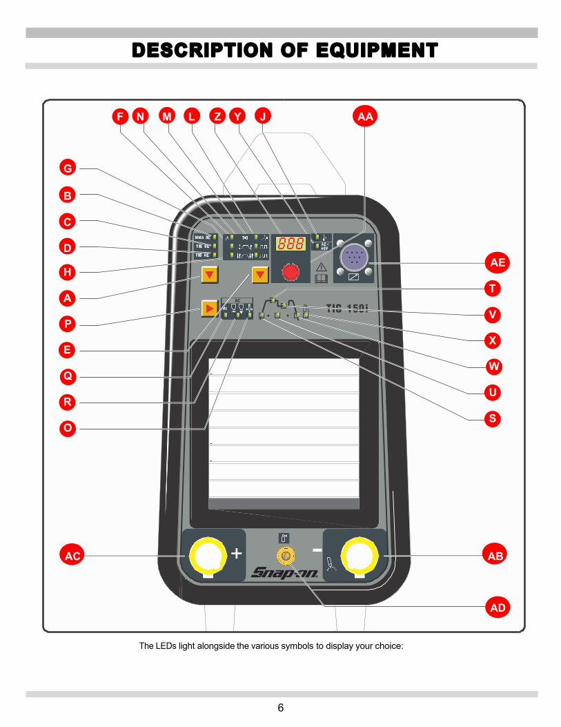
The LEDs light alongside the various symbols to display your choice:
F N M L Z Y J AA
G
B
C
D AE
H T
A V
P X
E W
Q U
R S
O AC AB
AD
DESCRIPTION OF EQUIPMENT
+ -

7
A - Procedure selector switch (Left-hand “down arrow” Key This push-button selects the welding procedure (MMA or TIG).When selected, one of the following LEDs lights:
B C o r D E Mode key. (Right-hand “down” arrow key.)
When selected, one of the following LEDs lights: F, G, H, L, M, N TIG mode there will always be two LEDs lit: one indicating HF or striking start mode, the other continuous or pulse mode in 2 or 4 stage.
F - LED. TIG welding with arc started without high frequency. To light the arc, press the torch trigger and touch the tungsten electrode to the work piece, then lift it. This move must be quick and decisive (0.3 sec.). Use this process when high frequency is not permitted.
L – LED TIG welding with arc started with high frequency.
To light the arc, press the torch trigger: a high voltage frequency pilot spark will light the arc.
G - LED. Continuous 2-stage TIG welding (manual).
When the torch trigger is pressed, the current begins. When the trigger is released, returns to zero. In this position, you may connect the optional pedal control accessory (TIGINVFP).
H - LED. Continuous 4-stage TIG welding (automatic).
This program differs from the previous one in that the arc is both started and shut off by pressing and releasing the torch trigger. M - LED. Pulsed 2-stage TIG welding (manual). When the torch trigger is pressed, the current begins. When the trigger is released, returns to zero. In this position, you may connect the optional pedal control accessory (TIGINVFP). N - LED. Pulsed 4-stage TIG welding (Automatic) This program differs from the previous one in that the arc is both started and shut off by pressing and releasing the torch trigger.
The Pulsed welding feature varies the weld current from the main welding current (Peak Amperage – high heat) and the second level of welding or base current (Background Amperage – low heat) levels. The TIG150i has two (2) different weld settings for the pulse features 2-stage TIG welding (manual) M – LED or 4-stage TIG welding (automatic) N - LED.
The Pulse frequency is adjustable from .16 to 250 pulses per second by selecting the mode U and setting the value with the knob AA. The duration of total time “on” between “High heat” and “Low heat” are equal.
“LED T ” – Main welding current (Peak Amperage – high heat)
This value is usually set somewhat higher than it would be set for a non-pulsed weld.
“LED V ” – Second level of welding or base current (Background Amperage – low heat)
This of course would be set lower than Main welding current. This value cannot be higher than the Main welding current. Once the base current V is set (a percentage in respect to the main current is established), so this value will change automatically when increasing or decreasing the Main current T .
“LED U ” – Pulse frequency (Pulses per Second . 16 – 250 HZ) Is the number of times per second that the welding current achieves main welding current (Peak Amperage – high heat).
Some of the advantages: • Good Penetration with less heat input to material
“burn through”. • Less distortion. • Good control of the pool when welding out of
position. • Ease of welding thin materials. • Ease of welding materials of dissimilar thickness. • Helps weld training. • Smaller bead profile. • Smaller heat-affected zone.
DESCRIPTION OF EQUIPMENT cont’d
8
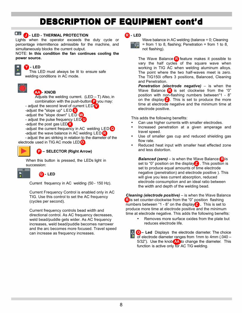
J - LED - THERMAL PROTECTION Lights when the operator exceeds the duty cycle or percentage intermittence admissible for the machine, and simultaneously blocks the current output. NOTE: In this condition the fan continues cooling the power source.
Y - LED This LED must always be lit to ensure safe welding conditions in AC mode.
AA - KNOB Adjusts the welding current. (LED – T) Also, in combination with the push-button P, you may:
- adjust the second level of current LED V -adjust the "slope up" LED S -adjust the "slope down" LED W - adjust the pulse frequency LED U -adjust the post gas LED X -adjust the current frequency in AC welding LED Q -adjust the wave balance in AC welding LED R
- adjust the arc striking in relation to the diameter of the electrode used in TIG AC mode LED O .
P – SELECTOR (Right Arrow)
When this button is pressed, the LEDs light in succession:
Q - LED
Current frequency in AC welding (50 - 150 Hz). Current Frequency Control is enabled only in AC TIG. Use this control to set the AC frequency (cycles per second). Current frequency controls bead width and directional control. As AC frequency decreases, weld bead/puddle gets wider. As AC frequency increases, weld bead/puddle becomes narrower and the arc becomes more focused. Travel speed can increase as frequency increases.
R - LED Wave balance in AC welding (balance = 0; Cleaning = from 1 to 8, flashing; Penetration = from 1 to 8, not flashing).
The Wave Balance R feature makes it possible to vary the half cycles of the square wave when working in TIG AC when welding aluminum alloys. The point where the two half-waves meet is zero. The TIG150i offers 3 positions, Balanced, Cleaning and Penetration. Penetration (electrode negative) – is when the Wave Balance R is set clockwise from the “0” position with non-flashing numbers between“1 - 8” on the display Z . This is set to produce the more time at electrode negative and the minimum time at electrode positive.
This adds the following benefits: • Can use higher currents with smaller electrodes. • Increased penetration at a given amperage and
travel speed. • Use of smaller gas cup and reduced shielding gas
flow rate. • Reduced heat input with smaller heat effected zone
and less distortion. Balanced (zero) – is when the Wave Balance R is set to “0” position on the display Z . This position is set to produce equal amounts of time electrode negative (penetration) and electrode positive ). This will give you less current absorption, reduced electrode consumption and an ideal ratio between the width and depth of the welding bead.
Cleaning (electrode positive) – is when the Wave Balance R is set counter-clockwise from the “0” position flashing numbers between “1 - 8” on the display Z . This is set to produce more time at electrode positive and the minimum time at electrode negative. This adds the following benefits:
• Removes more surface oxides from the plate but reduces electrode life.
O – Led Displays the electrode diameter. The choice of electrode diameter ranges from 1mm to 4mm (.040 – 5/32”). Use the knob AA to change the diameter. This function is active only for AC TIG welding.
DESCRIPTION OF EQUIPMENT cont’d

9
S - LED Slope up. This is the time in which the current, starting from the minimum, reaches the set current value. (0-10 sec.)
Slope Up can be used to assist in preheating cold material prior to depositing filler material, or to ensure a soft start on higher amperage settings.
T - LED Main welding current. (10-130A in MMA and 5-150A in TIG) V - LED Second level of welding or base current. This current is always a percentage of the main. Pulsed 2-stage or Pulsed 4-stage only - Use the Second level of welding or base current to set the low current pulse of the weld amperage, which cools the weld puddle and affects overall heat input. This current is always a percentage of main current. U - LED Pulse frequency (0.16-250 Hz) The peak and base times are equal. These pulses and the base current level -V- between them (called the Second level of welding ) alternately heat and cool the molten weld puddle. The combined effect gives better control of penetration, bead width, undercutting, and heat input W - LED Slope down. This is the time in which the cur- rent reaches the minimum value and the arc. Slope Down should be used while welding materials that are crack sensitive, and/or to eliminate the crater at the end of the weld.
X - LED Post gas. Adjusts the time gas flows after welding ends. (0-30 sec.) Post Gas is required to cool the tungsten rod and weld puddle, and to prevent contamination of tungsten and weld. Increase post gas time if tungsten or welds have a dark appearance.
Note: only those LEDs that refer to the chosen welding mode will light; i.e., in continuous TIG welding the LED U , representing the pulse frequency, will not light. Each LED indicates the parameter that may be adjusted by means of the knob AA while the LED itself is lit. Five seconds after the last variation, the LED involved will shut off; the main welding current will be displayed, and the corresponding LED T lights.
AE - 10-PIN CONNECTOR The following remote controls are connected to this connector: a) foot control or on/off button. b) torch with start button. c) torch with variable amperage device.
General Notes
Make sure the insulation of the cables, electrode clamps, sockets and plugs are intact, and that the size and length of the welding cables are compatible with the current used. AB - Negative output terminal Plug the TIG torch in here.
AC -Positive output terminal (+). Plug the “ground” cable in here.
AD - 1/4 GAS OUTLET FITTING
DESCRIPTION OF EQUIPMENT cont’d
10
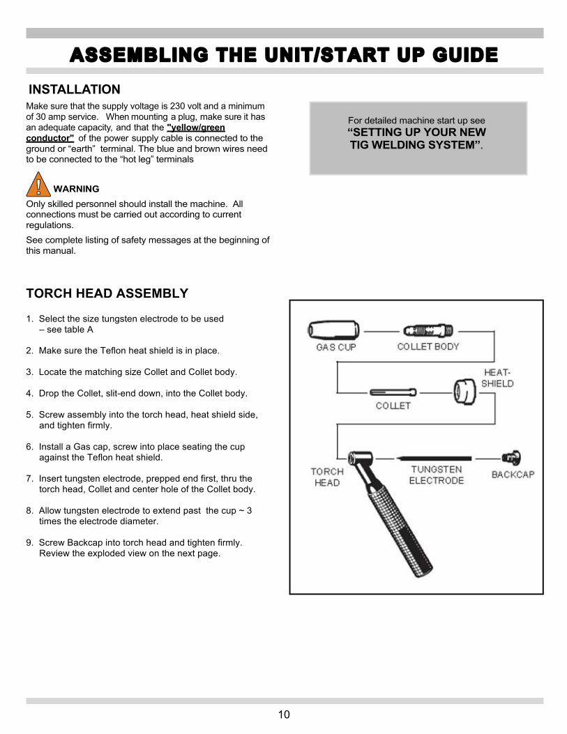
INSTALLATION Make sure that the supply voltage is 230 volt and a minimum of 30 amp service. When mounting a plug, make sure it has an adequate capacity, and that the "yellow/green conductor" of the power supply cable is connected to the ground or “earth” terminal. The blue and brown wires need to be connected to the “hot leg” terminals WARNING Only skilled personnel should install the machine. All connections must be carried out according to current regulations. See complete listing of safety messages at the beginning of this manual. TORCH HEAD ASSEMBLY 1. Select the size tungsten electrode to be used
– see table A 2. Make sure the Teflon heat shield is in place. 3. Locate the matching size Collet and Collet body. 4. Drop the Collet, slit-end down, into the Collet body. 5. Screw assembly into the torch head, heat shield side,
and tighten firmly. 6. Install a Gas cap, screw into place seating the cup
against the Teflon heat shield. 7. Insert tungsten electrode, prepped end first, thru the
torch head, Collet and center hole of the Collet body. 8. Allow tungsten electrode to extend past the cup ~ 3
times the electrode diameter. 9. Screw Backcap into torch head and tighten firmly.
Review the exploded view on the next page.
ASSEMBLING THE UNIT/START UP GUIDE
For detailed machine start up see “SETTING UP YOUR NEW TIG WELDING SYSTEM”.

11
TIG WELDING – GENERAL
aluminum, aluminum alloys, brass and magnesium, while
stainless steel, iron and copper. 1. Connect the earth (work) cable connector to the
positive pole (+) (AC) of the welding machine, and the clamp to the work piece as close as possible to the welding point, making sure there is good electrical contact.
2. Connect the power connector of the TIG torch to the negative pole (-) (AB) of the welding machine.
3. Connect the foot pedal or on/off switch control plug to the welding machine connector AE.
4. Connect the torch gas hose fitting to the gas outlet fitting AD on the machine, and the gas hose from the cylinder pressure regulator to the gas fitting AG on the rear panel.
AF – switch Turns the machine on and off. 0 = Off l = On
AG - gas inlet fitting
DANGER Do not touch live parts and output terminals while the machine is powered. Read complete listing of safety messages at the beginning of this manual.
1. The first time the machine is turned on, select the process and mode using the push-buttons A and E , and the welding parameters by means of the key P and the knob AA .
2. The type and diameter of the electrode to be used must be selected according to table A:
TABLE AInches/mm DC AC (frequency 50/60Hz)
Pos. Max Penetration Pos. Balanced zero Pos. Max Cleaning Electrode Type
. Tungsten
Thorium 2% Red
Tungsten Pure Green
Tungsten Zr 0,8% White
Tungsten Pure Green
Tungsten Zr 0,8% White
Tungsten Pure Green
Tungsten Zr 0,8% White
1/16in 1.6mm 70A – 150A 50A – 100A 70A – 150A 30A – 60A 50A – 80A 20A – 40A 30A – 60A 3/32in 2.4mm 150A – 250A 100A – 160A 140A – 235A 60A – 120A 80A – 140A 40A – 100A 60A – 120A
1/8in 3.2mm 200A – 350A 150A – 210A 225A – 325A 80A – 160A 100A – 180A 60A – 140A 80A – 160A 5/32in 4mm 300A – 400A 200A – 275A 300A – 400A 100A – 240A 150A – 280A 80A – 200A 150A – 250A
TIG WELDING - INTRODUCTION
AF
AG
By selecting the TIG AC welding mode you may weld
selecting TIG DC allows you to weld steels,
12
TIG WELDING – INTRODUCTION cont’d
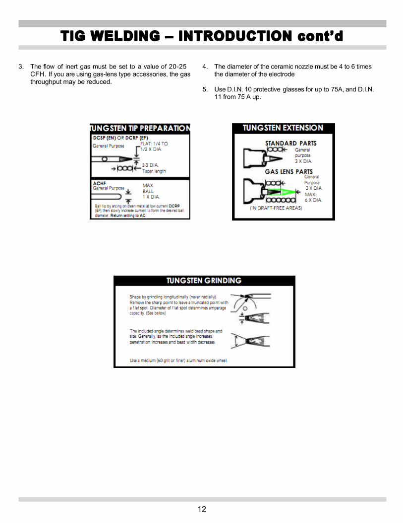
3. The flow of inert gas must be set to a value of 20-25 CFH. If you are using gas-lens type accessories, the gas throughput may be reduced.
4. The diameter of the ceramic nozzle must be 4 to 6 times the diameter of the electrode
5. Use D.I.N. 10 protective glasses for up to 75A, and D.I.N. 11 from 75 A up.

13
TIG Welding DC Basic Setup • With High Frequency Start • Using the On/Off Switch
Push the procedure selector switch (Left Hand Down Arrow). This push-button selects the welding procedure (MMA or TIG). When selected, one of the following LEDs lights: B , C , or D Push the button until the TIG DC LED lights .
Then push the Mode Key E (Right Hand Down Arrow). When selected, one of the following LEDs lights: F,G,H,L,M,N. Continue to push the button until the L LED lights along with the G LED.
L - LED. TIG welding with arc started with high frequency.
G LED. Continuous 2-stage TIG welding (manual).
P - SELECTOR (Right Arrow) When this button is pushed, the following LEDs light in succession:
S - LED Slope up. This is the time in which the current, starting from the minimum, reaches the set current value. (0-10 sec.)
AA – Knob Adjusts the slope up time while watching the Z display.
Z – Display Displays the settings selected. Set the slope up to “0” seconds.
Push the P – Selector (Right Arrow) until the T – LED main welding current display lights.
(10-130A in MMA and 5-150A in TIG)
Turn the AA knob while watching the Z display.
Z DISPLAY Adjust the display to the required main welding amperage. Rule of Thumb: “1 amp per .001 of plate thickness. (.125 =
~125 amps)
** May require multiple passes.
Push the P – Selector (Right Arrow) until the W – LED main welding current display lights.
W - LED Slope down. This is the time in which the current reaches the minimum and the arc shuts off. (0-10 seconds). Turn the AA -Knob watching the Z - Display.
Set the slope down to “0” seconds.
Push the P – Selector (Right Arrow) until the X – LED post gas display lights.
Post Gas Adjusts the time gas flows after the welding ends. ( 0-30 seconds) Turn the AA - Knob watching the Z - Display.
Set the post gas to “10” seconds.
Basic TIG DC Setup is Complete.
DC TIG WELDING
** **

14
TIG AC Welding Mode Basic Setup • With High Frequency Start • Using On/Off Button
Push the procedure selector switch (Left Hand Down Arrow). This push-button selects the welding procedure (MMA of TIG). When selected, one of the following LEDs lights: B , C , or D
Then push the Mode Key E (Right Hand Down Arrow).
When selected, one of the following LEDs lights: F,G,H,L,M,N. Continue to push the button until the L LED lights along with the G LED.
L - LED. TIG welding with arc started with high frequency.
G LED. Continuous 2-stage TIG welding (manual).
Push the P – Selector (Right Arrow) until the Q – LED current frequency display lights.
adjusted from 50 – 150 Hz. Turn the AA - Knob watching the Z - Display.
Set the current frequency to “60” Hz.
Push the P – Selector (Right Arrow) until the R – LED wave balance display lights.
R - LED
settings, balance = 0; Cleaning from 1-8, Penetration from 1-8. Turn the AA - Knob watching the Z - Display.
Set the wave balance to the “0” position.
Push the P – Selector (Right Arrow) until the O – LED electrode diameter display lights.
Displays the electrode diameter. The choice of electrode diameter ranges from 1mm to 4mm. Turn the AA - Knob watching the Z - Display.
Set the electrode diameter to the size recommended in Table “A”. EX.(3/32” = 2.4 mm).
Push the P – Selector (Right Arrow) until the S – LED slope up display lights.
S - LED Slope up. This is the time in which the current, starting from the minimum, reaches the set current value. (0-10 sec.)
AC TIG WELDING
Push the button until the TIG D LED lights .
Current frequency in AC welding mode. Can be
Wave balance in AC welding. There are three possible

15
Turn the AA -Knob watching the Z - Display.
Set the slope up to “0” seconds.
Push the P – Selector (Right Arrow) until the T – LED main welding current display lights.
(10-130A in MMA and 5-150A in TIG)
Turn the AA knob while watching the Z display.
Z DISPLAY Adjust the display to the required main welding amperage. Rule of Thumb: “1 amp per .001 of plate thickness.
(.125 = ~125 amps)
Use the following as a guide for setting up the amperage:
** May require multiple passes.
Push the P – Selector (Right Arrow) until the W – LED slope down display lights.
W - LED Slope down. This is the time in which the current reaches the minimum and the arc shuts off. (0-10 seconds). Turn the AA - Knob watching the Z - Display.
Set the slope down to “0” seconds.
Push the P – Selector (Right Arrow) until the X – LED post gas display lights.
Post Gas Adjusts the time gas flows after the welding ends. ( 0-30 seconds) Turn the AA - Knob watching the Z - Display.
Set the post gas to “10” seconds. Basic TIG AC Setup is Complete
AC TIG WELDING cont’d
** **

16
How to Setup the Optional Variable Amperage Foot Pedal or Remote Finger Amp Control (RAD).
• Using High Frequency Start • TIG AC Mode
The Foot Pedal allows the welder to remotely control the amperage from 5 amps minimum to 150 amps maximum shown on the LED Z display.
Install the Foot Pedal or RAD control plug in the AE receptacle.
Push the procedure selector switch (Left Hand Down Arrow). This push-button selects the welding procedure (MMA or TIG). When selected, one of the following LEDs lights: B , C , or D
Then push the Mode Key E (Right Hand Down Arrow).
When selected, one of the following LEDs lights: F,G,H,L,M,N. Continue to push the button until the L LED lights along with the G LED.
L - LED. TIG welding with arc started with high frequency. ---NOT AVAILABLE IN THE MMA MODE
G LED. Continuous 2-stage TIG welding (manual).
Push the P – Selector (Right Arrow) until the T – LED main welding current display lights.
(10-130A in MMA and 5-150A in TIG)
Activate the foot pedal or RAD to the maximum (pedal or slider fully depressed) position. While holding down the pedal to maximum,
turn the AA knob while watching the Z display.
Z DISPLAY Adjust the amperage to the approximate current that is required using the basic rule of thumb “one amp per thousandths of material thickness. Ex. 1/8” inch = .125 thousands so set the amps to ~125.
Push down on the pedal or slide the RAD.
The gas should purge. High frequency should activate. Amperage on the display Z should range from
5 to 125 amps.
NOW BEGIN TO WELD.
OPTIONAL FOOT PEDAL/ REMOTE AMPERAGE CONTROL
Push the button until the TIG AC LED lights .
17
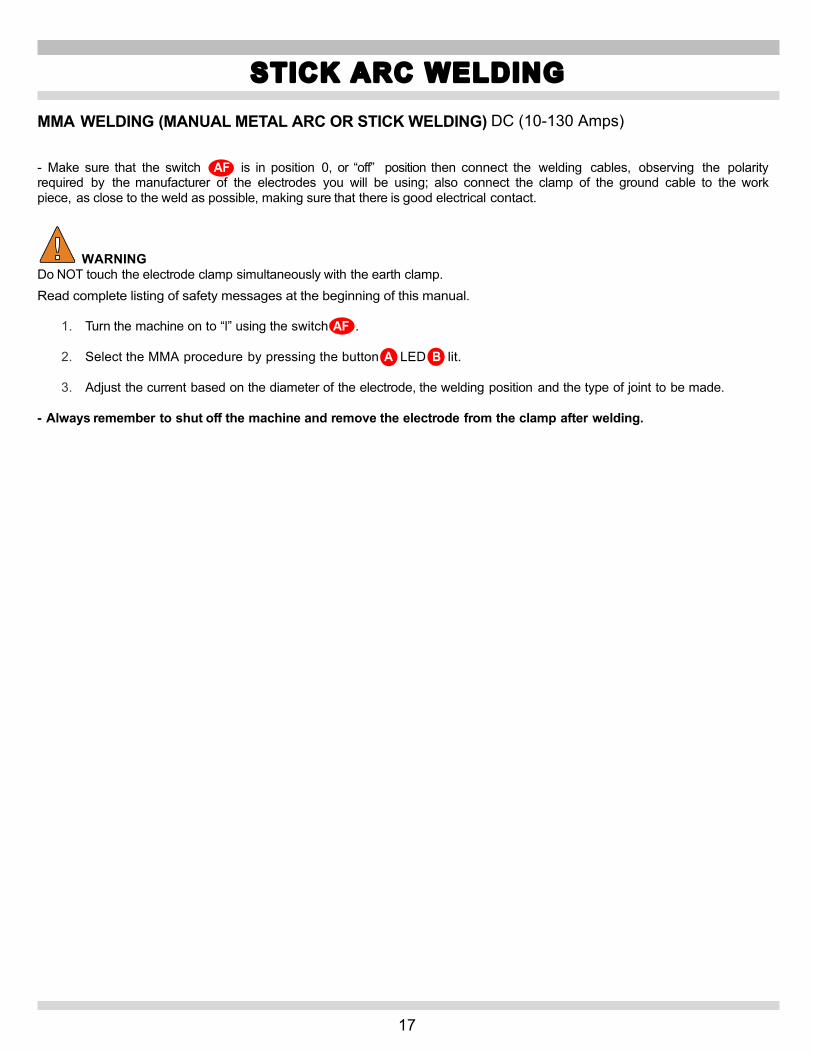
MMA WELDING (MANUAL METAL ARC OR STICK WELDING) DC (10-130 Amps) - Make sure that the switch AF is in position 0, or “off” position then connect the welding cables, observing the polarity required by the manufacturer of the electrodes you will be using; also connect the clamp of the ground cable to the work piece, as close to the weld as possible, making sure that there is good electrical contact. WARNING Do NOT touch the electrode clamp simultaneously with the earth clamp. Read complete listing of safety messages at the beginning of this manual.
1. Turn the machine on to “l” using the switch AF .
2. Select the MMA procedure by pressing the button A LED B lit.
3. Adjust the current based on the diameter of the electrode, the welding position and the type of joint to be made. - Always remember to shut off the machine and remove the electrode from the clamp after welding.
STICK ARC WELDING

18
DESCRIPTION OF PROTECTIVE DEVICES Thermal protection This machine is protected by a temperature probe, which prevents the machine from operating if the allowable temperatures are exceeded. Under these conditions the fan keeps running and the LED J lights. The duty cycle of the welder has been exceeded if the welder overheats. Duty cycle of a welding power source is the percentage of a ten minute period that the welder can operate without causing harm to the welder. Ex. A 60% duty cycle means that the welder can operate for 6 minutes and should cool for 4 minutes. Block Protections This welding machine is equipped with various safety devices that stop the machine before it can suffer damage. In the event of a malfunction, the letter E may appear on the display Z , followed by a flashing number: 52 = Start button pressed during startup. 53 = Start button pressed during thermostat reset. In both cases, release the start button. The machine stop is signaled by the flashing LED J . When this occurs, it signals: 1) During the start-up phase, the power status of the
machine.
2) After the start-up phase, incorrect supply voltage.
3) With the machine running, that the voltage has fallen below 118V.
4) With the machine running, that the supply voltage is above
280V.
5) During welding, that the voltage exceeds 300V.
switch, wait 5 seconds, and switch it on again. If the problem has been corrected, the welding machine will begin operating again. NOTE: If the supply voltage is below 170V at start-up, no LED will light and the fan is powered. If the message E2 appears on the display, the machine requires technical service. 800-ABC-WELD
TIG WELDER MAINTENANCE Any maintenance operation must be carried out by qualified personnel. GENERAL TIG WELDER MAINTENANCE In the case of maintenance inside the machine, make sure that the switch AF is in position "O" and that the power cord is disconnected from the mains. It is also necessary to periodically clean the interior of the machine from the accumulated metal dust, using compressed air. PRECAUTIONS AFTER REPAIRS. After making repairs, take care to organize the wiring so that there is secure insulation between the primary and secondary sides of the machine. Do not allow the wires to come into contact with moving parts or those that heat up during operation. Reassemble all clamps as they were on the original machine, to prevent a connection from occurring between the primary and secondary circuits should a wire accidentally break or be disconnected. Also mount the screws with geared washers as on the original machine.
TROUBLESHOOTING/MAINTENANCE
To restore operation, check the voltage. Then shut off the AC
19
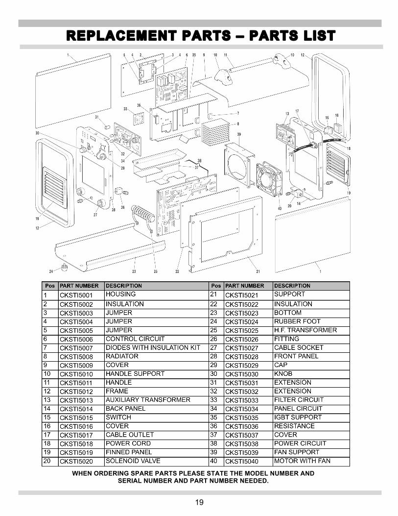
REPLACEMENT PARTS – PARTS LIST
WHEN ORDERING SPARE PARTS PLEASE STATE THE MODEL NUMBER AND SERIAL NUMBER AND PART NUMBER NEEDED.

20
REPLACEMENT PARTS – STANDARD AND OPTIONAL ACCESSORIES
41 42 43 44 46
47 49 50
51 52
45
48

21
WIRING DIAGRAM
22
Snap-on Tools Company Limited Two (2) Year Warranty
Snap-on Tools Company (the “Seller") warrants only to original purchasers who use the Equipment in their business that under normal use, care and service, the Equipment (except as otherwise provided herein) shall be free from defects in material and workmanship for two years from the date of original invoice. Seller does not provide any warranty for accessories used with the Equipment that are not manufactured by Seller. Seller limits torch assembly to a period of 30 days. SELLER'S OBLIGATIONS UNDER THIS WARRANTY ARE LIMITED SOLELY TO THE REPAIR OR, AT SELLER'S OPTION, REPLACEMENT OF EQUIPMENT OR PARTS WHICH TO SELLER'S SATISFACTION ARE DETERMINED TO BE DEFECTIVE AND WHICH ARE NECESSARY, IN SELLER'S JUDGMENT, TO RETURN THIS EQUIPMENT TO GOOD OPERATING CONDITION. NO OTHER WARRANTIES, EXPRESS OR IMPLIED OR STATUTORY, INCLUDING WITHOUT LIMITATION ANY IMPLIED WARRANTY OF MERCHANTABILITY OR FITNESS FOR A PARTICULAR PURPOSE, SHALL APPLY AND ALL SUCH WARRANTIES ARE HEREBY EXPRESSLY DISCLAIMED. SELLER SHALL NOT BE LIABLE FOR ANY INCIDENTAL, SPECIAL OR CONSEQUENTIAL COSTS OR DAMAGES INCURRED BY PURCHASERS OR OTHERS (including, without limitations, lost profits, revenues, and anticipated sales, business opportunities or goodwill, or interruption of business and any other injury or damage). This warranty does not cover (and separate charges for parts, labor and related expenses shall apply to) any damage to, malfunctioning, inoperability or improper operation of the Equipment caused by, resulting from or attributable to (A) abuse, misuse or tampering; (B) alteration, modification or adjustment of the Equipment by other than Seller's authorized representatives; (e) installation, repair or maintenance (other than specified operator maintenance) of the Equipment or related equipment, attachments, peripherals or optional features by other than Seller's authorized representatives; (D) improper or negligent use, application, operation, care, cleaning, storage or handling; (E) fire, water, wind, lightning or other natural causes; (F) adverse environmental conditions, including, without limitation, excessive heat, moisture, corrosive elements, dust or other air contaminants, radio frequency interference, electric power failure, power line voltages beyond those specified for the Equipment. unusual physical, electrical or electromagnetic stress and/or any other condition outside of Seller's environmental specifications; (G) use of the Equipment in combination or connection with other equipment, attachments, supplies or consumables not manufactured or supplied by Seller; or (H) failure to comply with any applicable federal, state or local regulation, requirement or specification governing welders and related supplies or consumables. Repairs or replacements qualifying under this Warranty will be performed on regular business days during Seller's normal working hours within a reasonable time following purchaser's request. All requests for Warranty service must be made during the stated Warranty period. Proof of purchase date is required to make a Warranty request. This Warranty is nontransferable.
Snap-on Tools Company
Kenosha, Wisconsin 53141-1410 Technical Support Line 800-ABC-WELD
Customer Service and Technical Support 800-ABC-WELD
Monday – Friday 7:00 a.m. – 3:00 p.m. EST
Made in Italy Snap-on and Wrench “S” are trademarks of Snap-on Incorporated. ©Snap-on Incorporated 2011. All Rights Reserved. Printed in United States Snap-on, 2801 80th St., Kenosha, WI 53143 www.snapon.com
WARRANTY/SERVICE AND REPAIR