15-744 Computer Networks Background Material 1: Getting stuff from here to there Or How I learned to...
78
15-744 Computer Networks Background Material 1: Getting stuff from here to there Or How I learned to love OSI layers 1-3
-
Upload
maximillian-heath -
Category
Documents
-
view
214 -
download
0
Transcript of 15-744 Computer Networks Background Material 1: Getting stuff from here to there Or How I learned to...
15-744 Computer Networks
Background Material 1:
Getting stuff from here to there
Or
How I learned to love OSI layers 1-3
Outline
• Switching and Multiplexing
• Link-Layer
• Routing-Layer
• Physical-Layer Encoding
2

Packet vs. Circuit Switching
• Packet-switching: Benefits• Ability to exploit statistical multiplexing• More efficient bandwidth usage
• Packet switching: Concerns • Needs to buffer and deal with congestion:• More complex switches• Harder to provide good network services (e.g., delay
and bandwidth guarantees)
3
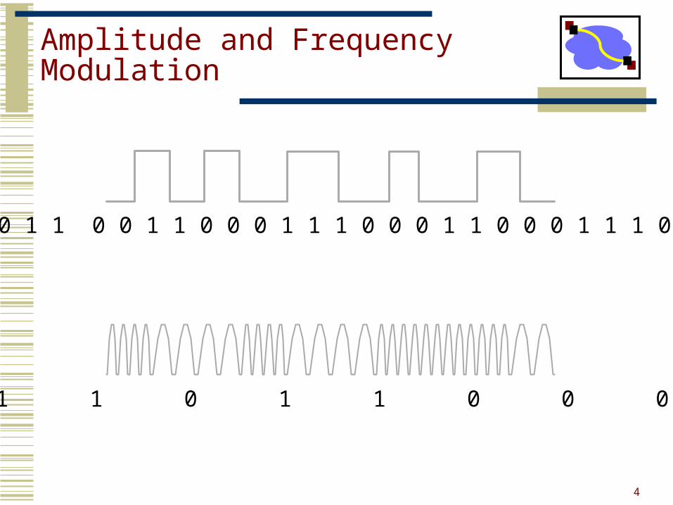
Amplitude and FrequencyModulation
0 0 1 1 0 0 1 1 0 0 0 1 1 1 0 0 0 1 1 0 0 0 1 1 1 0
0 1 1 0 1 1 0 0 0 1
4

Capacity of a Noisy Channel
• Can’t add infinite symbols - you have to be able to tell them apart. This is where noise comes in.
• Shannon’s theorem:• C = B x log(1 + S/N)• C: maximum capacity (bps)• B: channel bandwidth (Hz)• S/N: signal to noise ratio of the channel
• Often expressed in decibels (db). 10 log(S/N).• Example:
• Local loop bandwidth: 3200 Hz• Typical S/N: 1000 (30db)• What is the upper limit on capacity?
• Modems: Teleco internally converts to 56kbit/s digital signal, which sets a limit on B and the S/N.
5
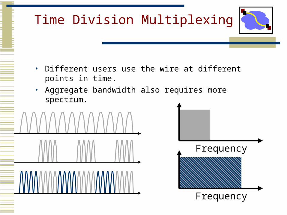
Time Division Multiplexing
• Different users use the wire at different points in time.• Aggregate bandwidth also requires more spectrum.
Frequency
Frequency
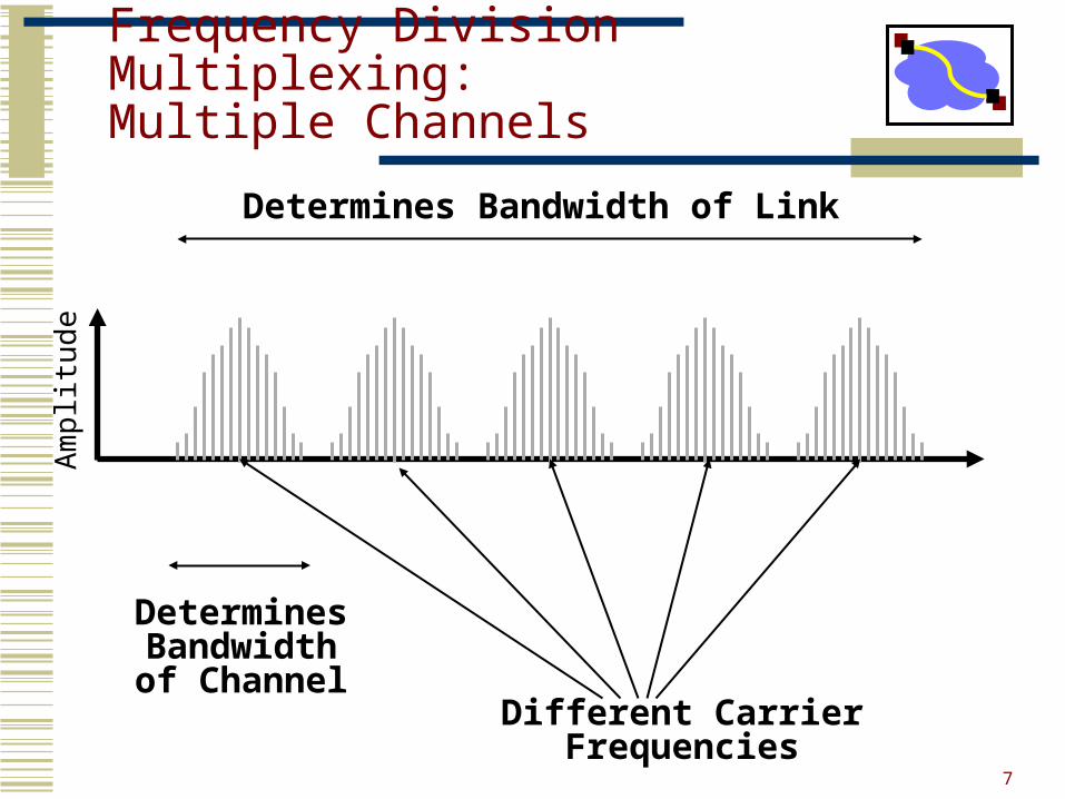
Frequency Division Multiplexing:Multiple Channels
Am
plitu
de
Different CarrierFrequencies
DeterminesBandwidthof Channel
Determines Bandwidth of Link
7
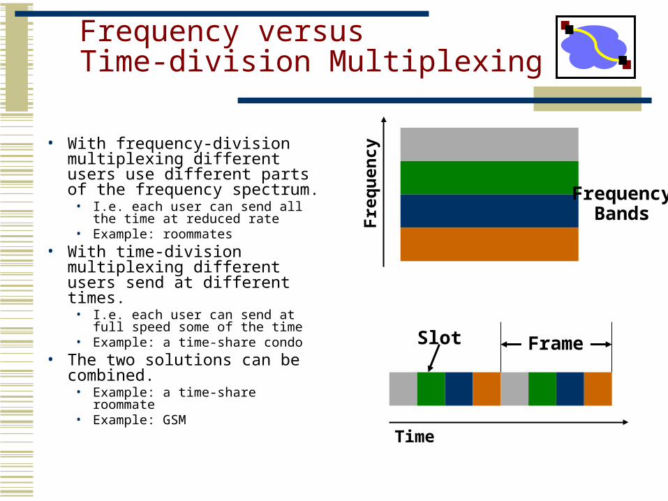
Frequency versus Time-division Multiplexing
• With frequency-division multiplexing different users use different parts of the frequency spectrum.
• I.e. each user can send all the time at reduced rate
• Example: roommates • With time-division multiplexing
different users send at different times.
• I.e. each user can send at full speed some of the time
• Example: a time-share condo• The two solutions can be
combined.• Example: a time-share roommate• Example: GSM
Fre
quen
cy
Time
FrequencyBands
Slot Frame
Outline
• Switching and Multiplexing• Link-Layer
• Ethernet and CSMA/CD• Bridges/Switches
• Routing-Layer• Physical-Layer
10
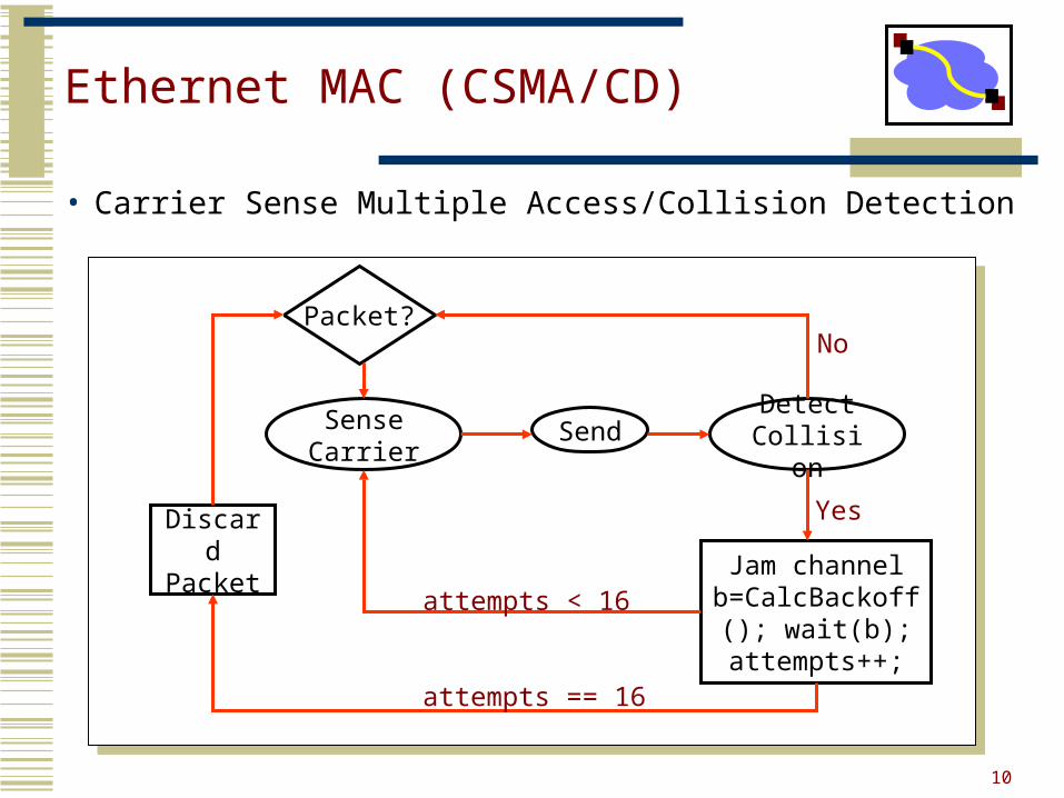
Ethernet MAC (CSMA/CD)
Packet?
Sense Carrier
Discard Packet
Send Detect Collision
Jam channel b=CalcBackoff();
wait(b);attempts++;
No
Yes
attempts < 16
attempts == 16
• Carrier Sense Multiple Access/Collision Detection
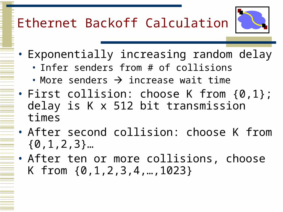
Ethernet Backoff Calculation
• Exponentially increasing random delay• Infer senders from # of collisions• More senders increase wait time
• First collision: choose K from {0,1}; delay is K x 512 bit transmission times
• After second collision: choose K from {0,1,2,3}…• After ten or more collisions, choose K from
{0,1,2,3,4,…,1023}
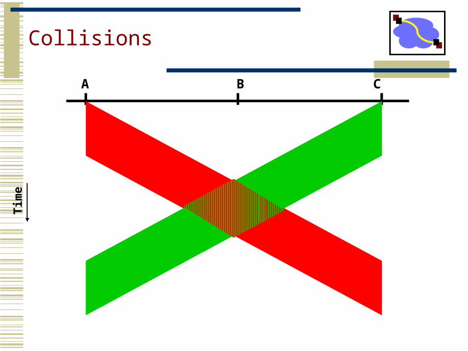
CollisionsT
ime
A B C
13
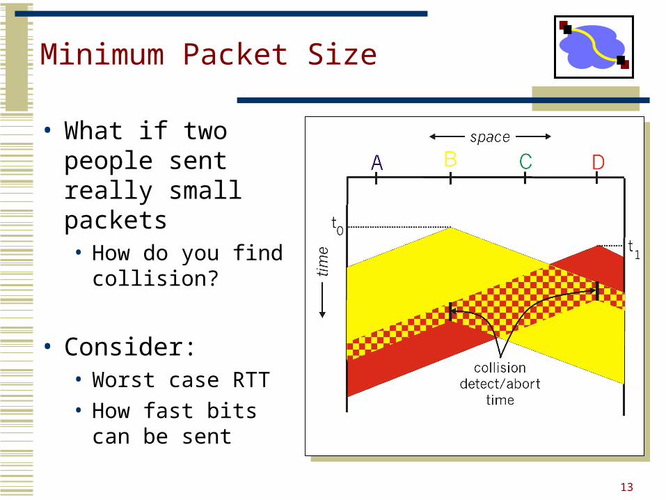
Minimum Packet Size
• What if two people sent really small packets• How do you find
collision?
• Consider:• Worst case RTT• How fast bits can
be sent
Ethernet Collision Detect
• Min packet length > 2x max prop delay• If A, B are at opposite sides of link, and B starts one link
prop delay after A
• Jam network for 32-48 bits after collision, then stop sending• Ensures that everyone notices collision
15
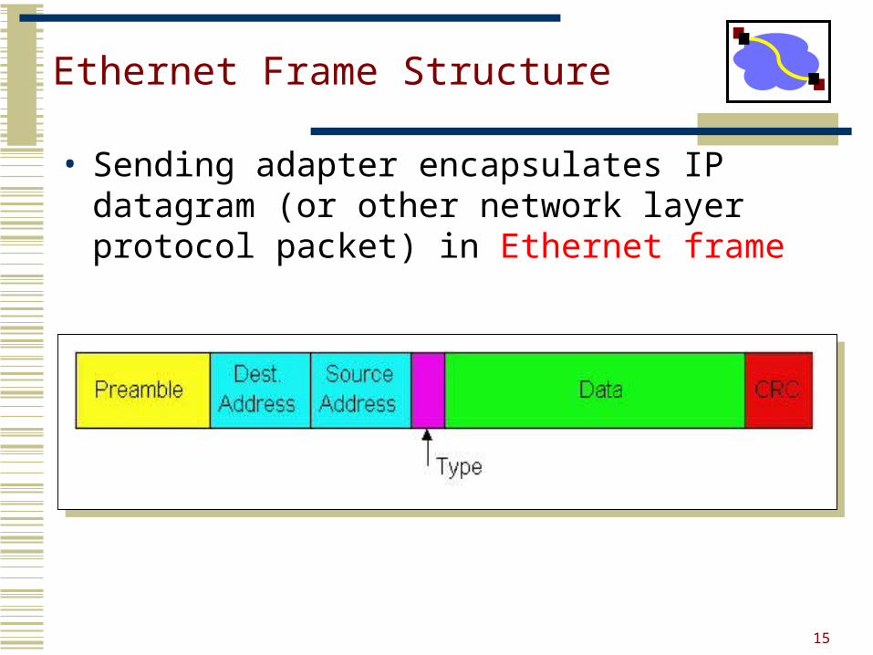
Ethernet Frame Structure
• Sending adapter encapsulates IP datagram (or other network layer protocol packet) in Ethernet frame
16
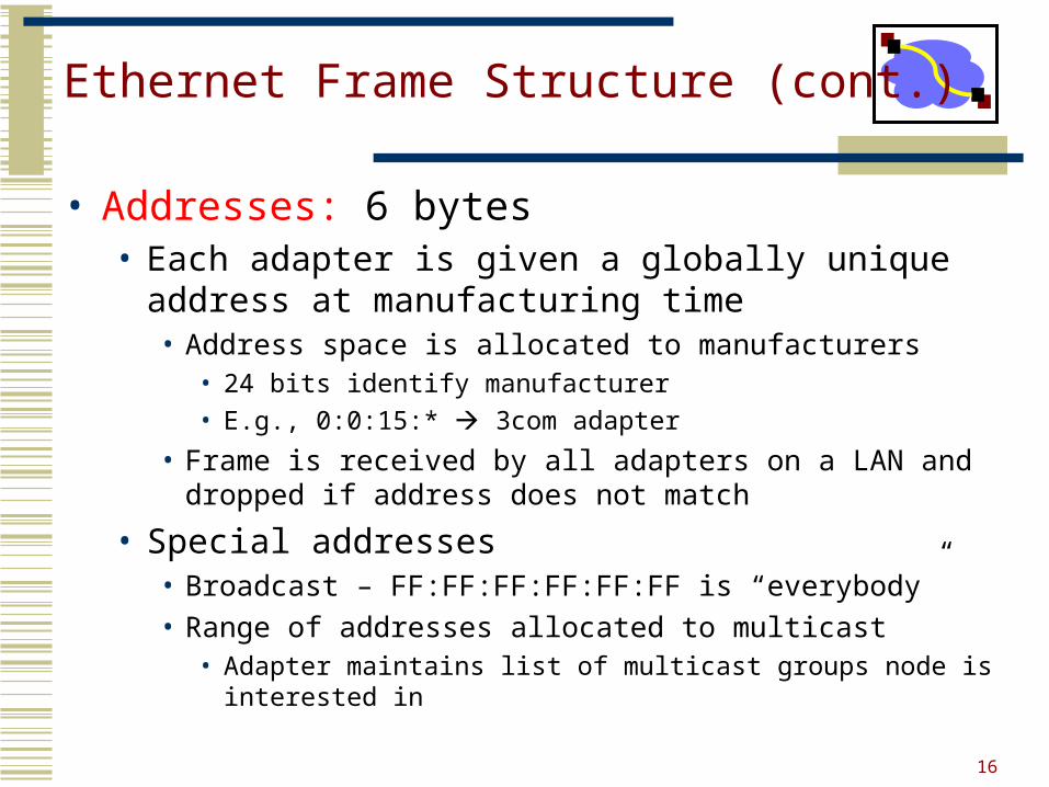
Ethernet Frame Structure (cont.)
• Addresses: 6 bytes• Each adapter is given a globally unique address at
manufacturing time• Address space is allocated to manufacturers
• 24 bits identify manufacturer
• E.g., 0:0:15:* 3com adapter
• Frame is received by all adapters on a LAN and dropped if address does not match
• Special addresses• Broadcast – FF:FF:FF:FF:FF:FF is “everybody”• Range of addresses allocated to multicast
• Adapter maintains list of multicast groups node is interested in
17
Summary
• CSMA/CD carrier sense multiple access with collision detection• Why do we need exponential backoff?• Why does collision happen?• Why do we need a minimum packet size?
• How does this scale with speed? (Related to HW)
• Ethernet• What is the purpose of different header fields?• What do Ethernet addresses look like?
• What are some alternatives to Ethernet design?
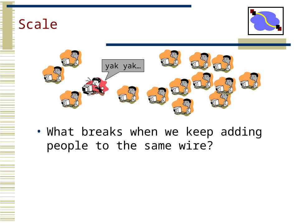
Scale
• What breaks when we keep adding people to the same wire?
yak yak…
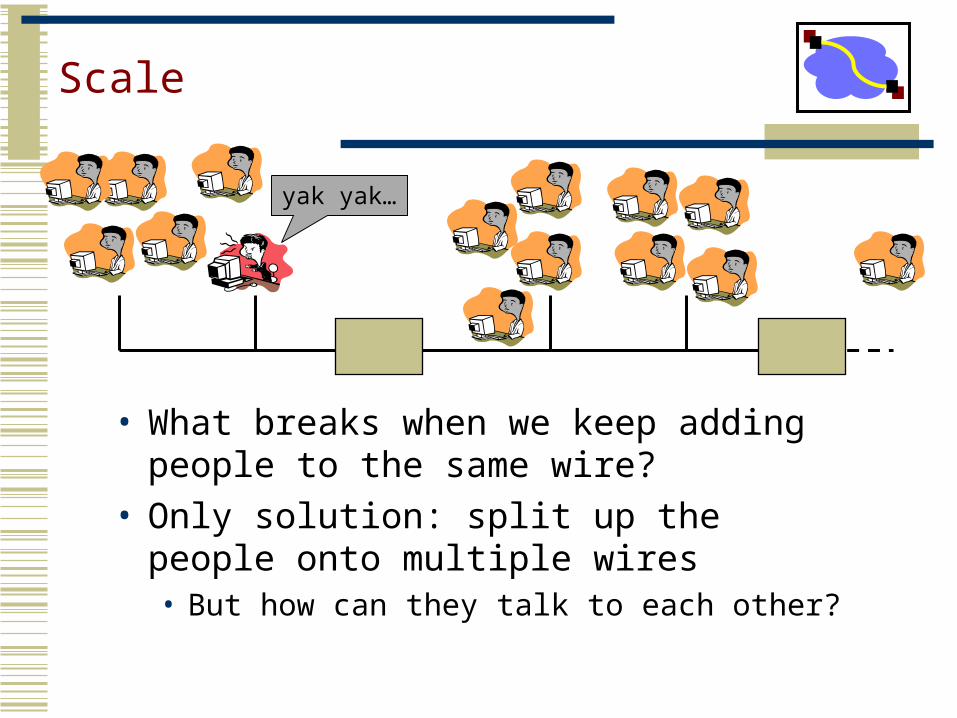
Scale
• What breaks when we keep adding people to the same wire?
• Only solution: split up the people onto multiple wires• But how can they talk to each other?
yak yak…
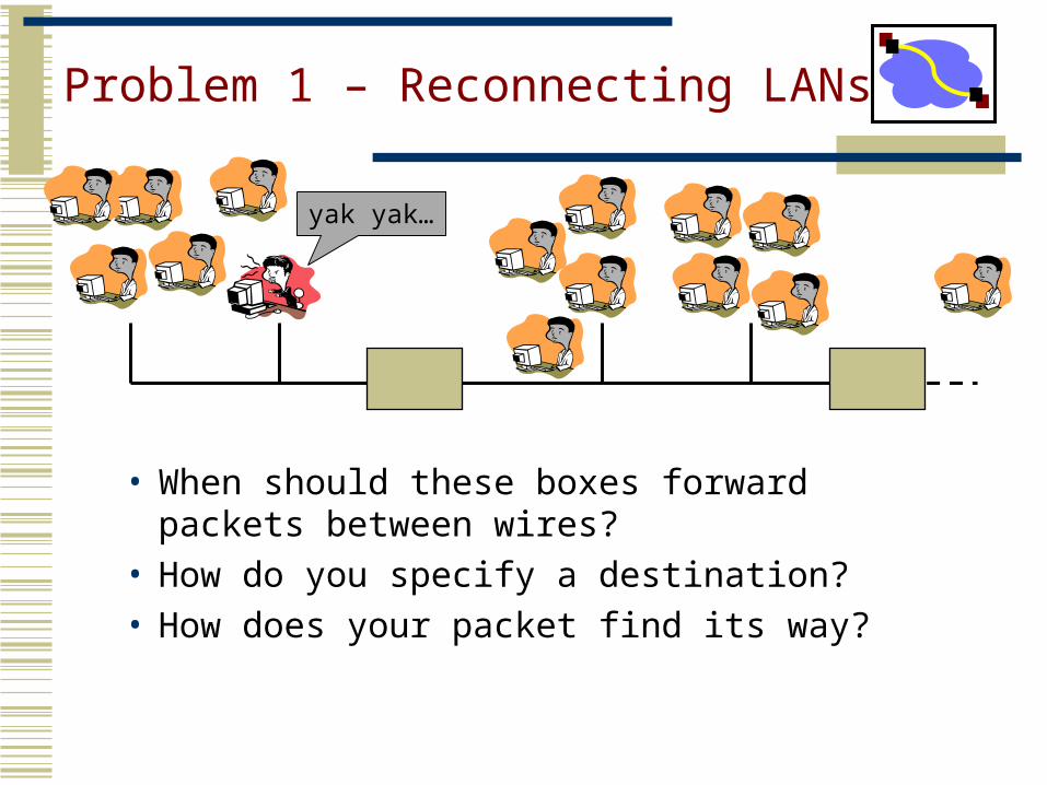
Problem 1 – Reconnecting LANs
• When should these boxes forward packets between wires?
• How do you specify a destination?• How does your packet find its way?
yak yak…

21
Transparent Bridges / Switches
• Design goals:• Self-configuring without hardware or software changes• Bridge do not impact the operation of the individual
LANs
• Three parts to making bridges transparent:1) Forwarding frames2) Learning addresses/host locations3) Spanning tree algorithm

22
Frame Forwarding
• A machine with MAC Address lies in the direction of number port of the bridge
• For every packet, the bridge “looks up” the entry for the packets destination MAC address and forwards the packet on that port.• Other packets are broadcast – why?
• Timer is used to flush old entries
8711C98900AA 2
MAC Address Port
A21032C9A591 199A323C90842 2
301B2369011C 2695519001190 3
15
Age
36
01
16
11
Bridge1
3 2
23
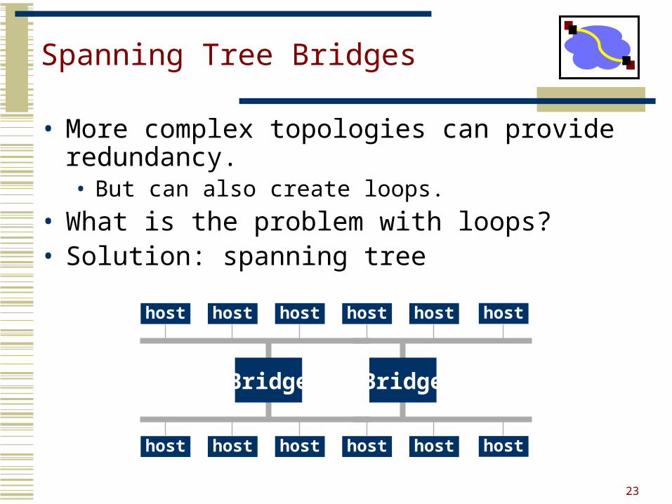
Spanning Tree Bridges
• More complex topologies can provide redundancy.• But can also create loops.
• What is the problem with loops?• Solution: spanning tree
host host host host host
host host host host host
host
host
Bridge Bridge
Outline
• Switching and Multiplexing• Link-Layer• Routing-Layer
• IP• IP Routing• MPLS
• Physical-Layer
24

IP Addresses
• Fixed length: 32 bits• Initial classful structure (1981) (not relevant now!!!)• Total IP address size: 4 billion
• Class A: 128 networks, 16M hosts• Class B: 16K networks, 64K hosts• Class C: 2M networks, 256 hosts
25
High Order Bits0 10 110
Format7 bits of net, 24 bits of host14 bits of net, 16 bits of host21 bits of net, 8 bits of host
ClassABC
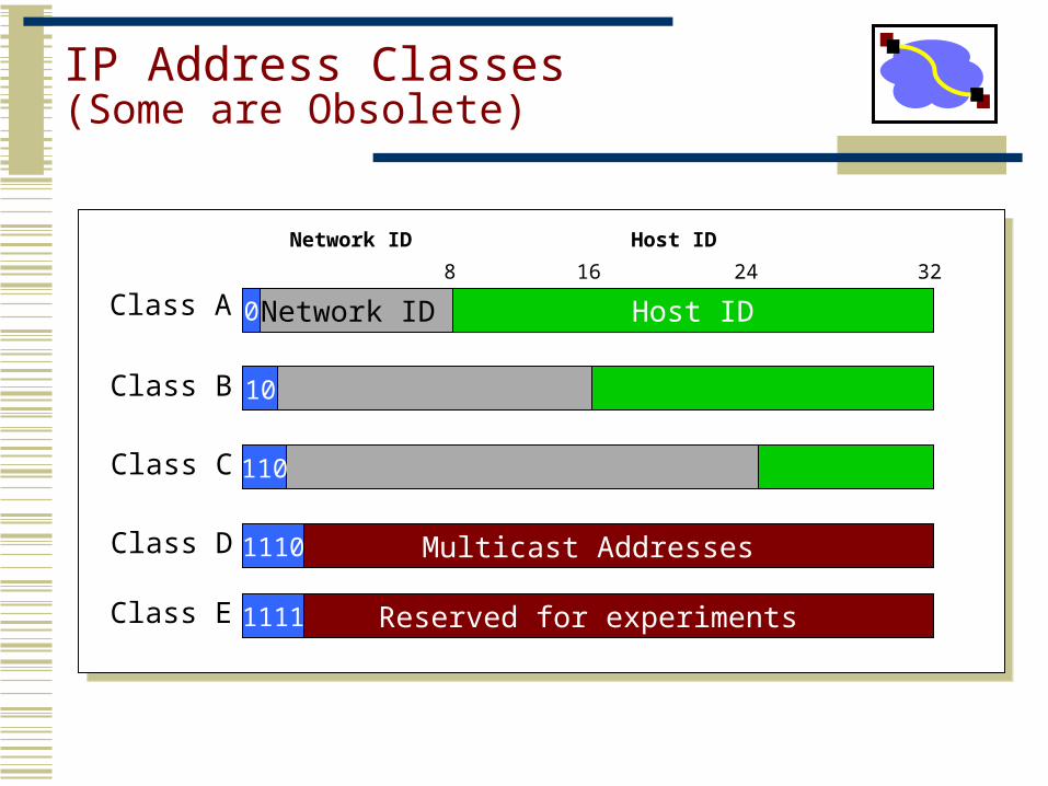
IP Address Classes(Some are Obsolete)
Network ID Host ID
Network ID Host ID
8 16
Class A32
0
Class B 10
Class C 110
Multicast AddressesClass D 1110
Reserved for experimentsClass E 1111
24
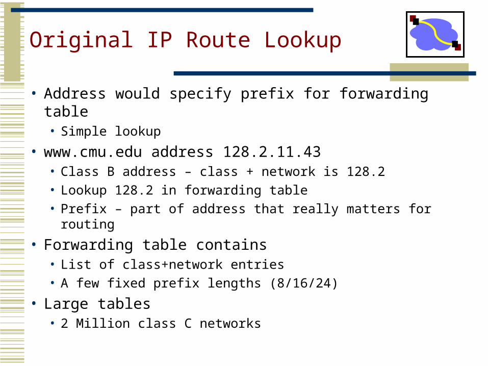
Original IP Route Lookup
• Address would specify prefix for forwarding table• Simple lookup
• www.cmu.edu address 128.2.11.43• Class B address – class + network is 128.2• Lookup 128.2 in forwarding table• Prefix – part of address that really matters for routing
• Forwarding table contains• List of class+network entries• A few fixed prefix lengths (8/16/24)
• Large tables• 2 Million class C networks
Subnet AddressingRFC917 (1984)
• Class A & B networks too big• Very few LANs have close to 64K hosts• For electrical/LAN limitations, performance or
administrative reasons
• Need simple way to get multiple “networks”• Use bridging, multiple IP networks or split up single
network address ranges (subnet)
• CMU case study in RFC• Chose not to adopt – concern that it would not be
widely supported
28
29
Aside: Interaction with Link Layer
• How does one find the Ethernet address of a IP host?
• ARP (Address Resolution Protocol)• Broadcast search for IP address
• E.g., “who-has 128.2.184.45 tell 128.2.206.138” sent to Ethernet broadcast (all FF address)
• Destination responds (only to requester using unicast) with appropriate 48-bit Ethernet address• E.g, “reply 128.2.184.45 is-at 0:d0:bc:f2:18:58” sent to
0:c0:4f:d:ed:c6

30
Classless Inter-Domain Routing(CIDR) – RFC1338
• Allows arbitrary split between network & host part of address • Do not use classes to determine network ID• Use common part of address as network number• E.g., addresses 192.4.16 - 192.4.31 have the first 20
bits in common. Thus, we use these 20 bits as the network number 192.4.16/20
• Enables more efficient usage of address space (and router tables) How?• Use single entry for range in forwarding tables• Combined forwarding entries when possible
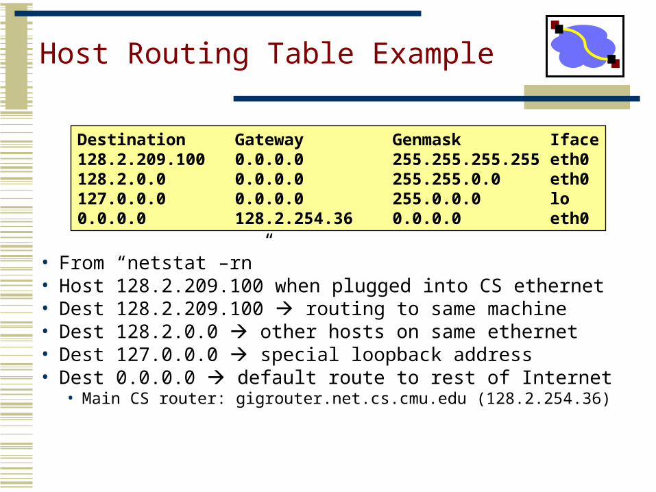
Host Routing Table Example
• From “netstat –rn”• Host 128.2.209.100 when plugged into CS ethernet• Dest 128.2.209.100 routing to same machine• Dest 128.2.0.0 other hosts on same ethernet• Dest 127.0.0.0 special loopback address• Dest 0.0.0.0 default route to rest of Internet
• Main CS router: gigrouter.net.cs.cmu.edu (128.2.254.36)
Destination Gateway Genmask Iface128.2.209.100 0.0.0.0 255.255.255.255 eth0128.2.0.0 0.0.0.0 255.255.0.0 eth0127.0.0.0 0.0.0.0 255.0.0.0 lo0.0.0.0 128.2.254.36 0.0.0.0 eth0
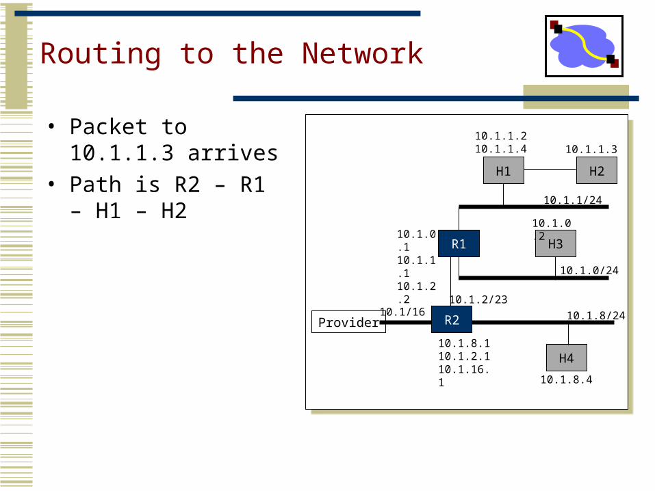
Routing to the Network
H2
H3
H4
R1
10.1.1/24
10.1.1.210.1.1.4
Provider10.1/16 10.1.8/24
10.1.0/24
10.1.1.3
10.1.2/23
R2
10.1.0.2
10.1.8.4
10.1.0.110.1.1.110.1.2.2
10.1.8.110.1.2.110.1.16.1
H1
• Packet to 10.1.1.3 arrives
• Path is R2 – R1 – H1 – H2
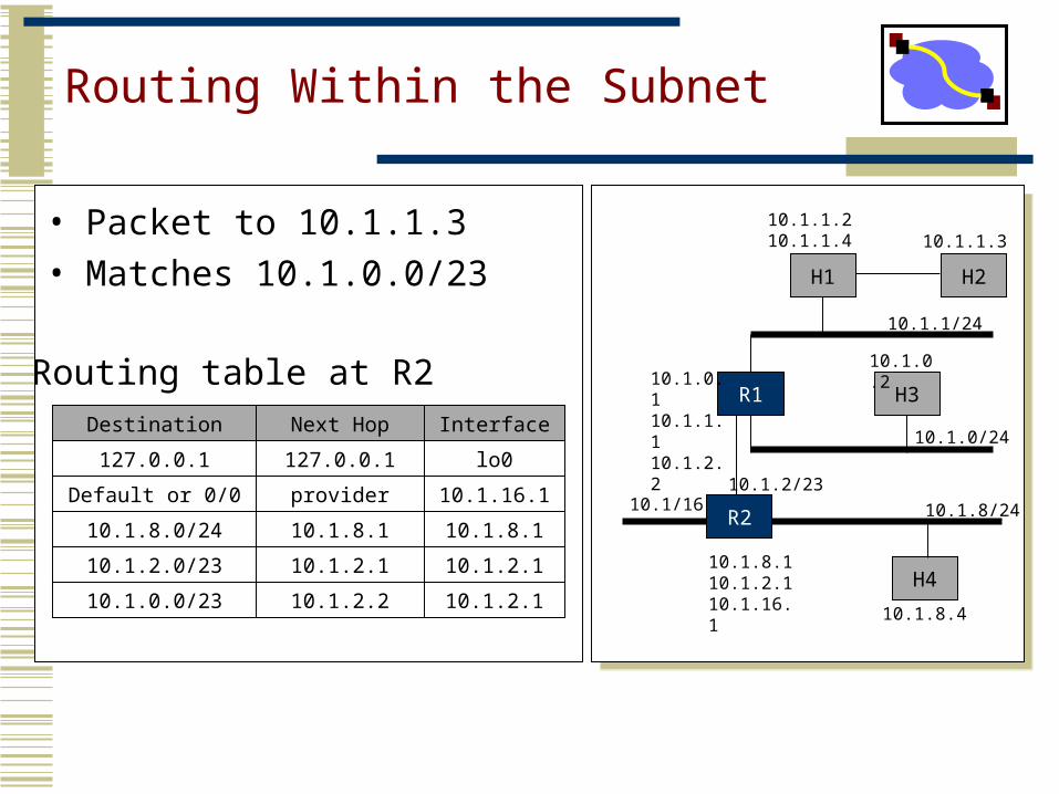
Routing Within the Subnet
Routing table at R2
H2
H3
H4
R1
10.1.1/24
10.1/16 10.1.8/24
10.1.0/24
10.1.1.3
10.1.2/23
R2
10.1.0.2
10.1.8.4
10.1.0.110.1.1.110.1.2.2
10.1.8.110.1.2.110.1.16.1
H1
Destination Next Hop Interface
127.0.0.1 127.0.0.1 lo0
Default or 0/0 provider 10.1.16.1
10.1.8.0/24 10.1.8.1 10.1.8.1
10.1.2.0/23 10.1.2.1 10.1.2.1
10.1.0.0/23 10.1.2.2 10.1.2.1
• Packet to 10.1.1.3• Matches 10.1.0.0/23
10.1.1.210.1.1.4
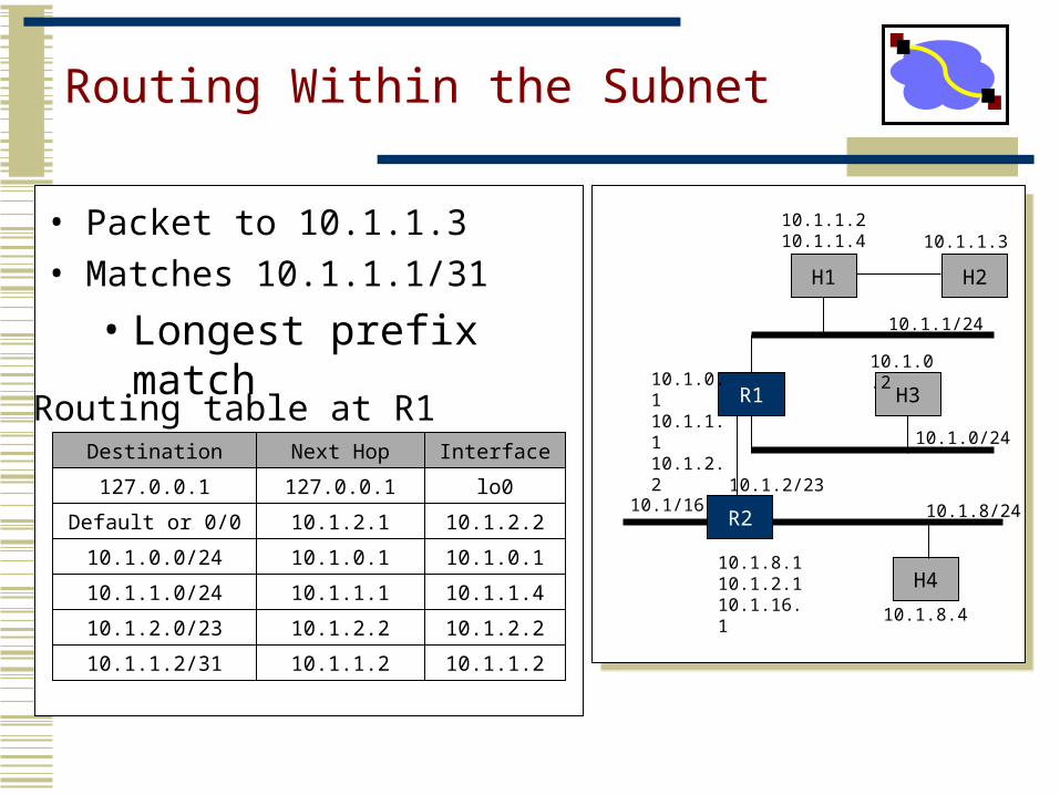
Routing Within the Subnet
H2
H3
H4
R1
10.1.1/24
10.1/16 10.1.8/24
10.1.0/24
10.1.1.3
10.1.2/23
R2
10.1.0.2
10.1.8.4
10.1.0.110.1.1.110.1.2.2
10.1.8.110.1.2.110.1.16.1
H1
Routing table at R1Destination Next Hop Interface
127.0.0.1 127.0.0.1 lo0
Default or 0/0 10.1.2.1 10.1.2.2
10.1.0.0/24 10.1.0.1 10.1.0.1
10.1.1.0/24 10.1.1.1 10.1.1.4
10.1.2.0/23 10.1.2.2 10.1.2.2
• Packet to 10.1.1.3• Matches 10.1.1.1/31
• Longest prefix match
10.1.1.2/31 10.1.1.2 10.1.1.2
10.1.1.210.1.1.4

Routing Within the Subnet
H2
H3
H4
R1
10.1.1/24
10.1/1610.1.8/24
10.1.0/24
10.1.1.3
10.1.2/23
R2
10.1.0.2
10.1.8.4
10.1.0.110.1.1.110.1.2.2
10.1.8.110.1.2.110.1.16.1
H1
Routing table at H1Destination Next Hop Interface
127.0.0.1 127.0.0.1 lo0
Default or 0/0 10.1.1.1 10.1.1.2
10.1.1.0/24 10.1.1.2 10.1.1.1
10.1.1.3/31 10.1.1.2 10.1.1.2
• Packet to 10.1.1.3• Direct route
• Longest prefix match
10.1.1.210.1.1.4
36
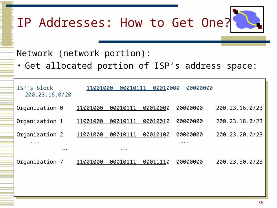
IP Addresses: How to Get One?
Network (network portion):• Get allocated portion of ISP’s address space:
ISP's block 11001000 00010111 00010000 00000000 200.23.16.0/20
Organization 0 11001000 00010111 00010000 00000000 200.23.16.0/23
Organization 1 11001000 00010111 00010010 00000000 200.23.18.0/23
Organization 2 11001000 00010111 00010100 00000000 200.23.20.0/23 ... ….. …. ….
Organization 7 11001000 00010111 00011110 00000000 200.23.30.0/23
37
IP Addresses: How to Get One?
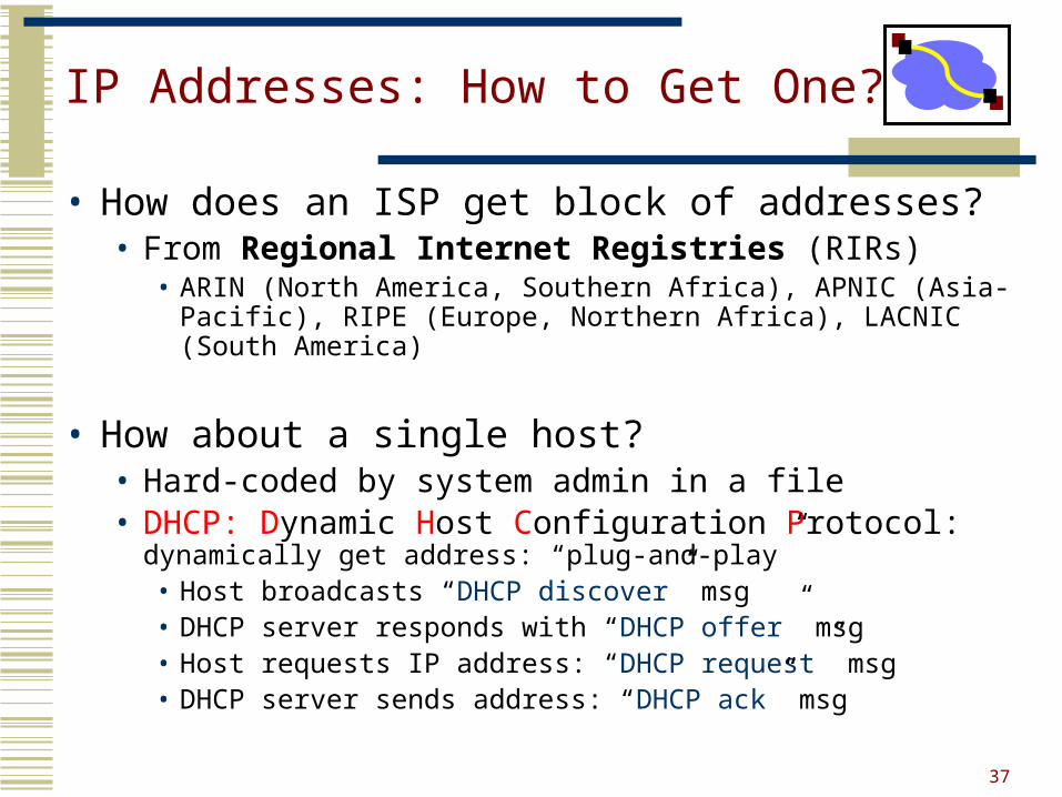
• How does an ISP get block of addresses?• From Regional Internet Registries (RIRs)
• ARIN (North America, Southern Africa), APNIC (Asia-Pacific), RIPE (Europe, Northern Africa), LACNIC (South America)
• How about a single host?• Hard-coded by system admin in a file• DHCP: Dynamic Host Configuration Protocol: dynamically
get address: “plug-and-play”• Host broadcasts “DHCP discover” msg• DHCP server responds with “DHCP offer” msg• Host requests IP address: “DHCP request” msg• DHCP server sends address: “DHCP ack” msg
38
IP Service Model
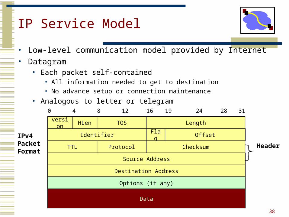
• Low-level communication model provided by Internet• Datagram
• Each packet self-contained• All information needed to get to destination• No advance setup or connection maintenance
• Analogous to letter or telegram0 4 8 12 16 19 24 28 31
version HLen TOS Length
Identifier Flag Offset
TTL Protocol Checksum
Source Address
Destination Address
Options (if any)
Data
Header
IPv4 PacketFormat
39
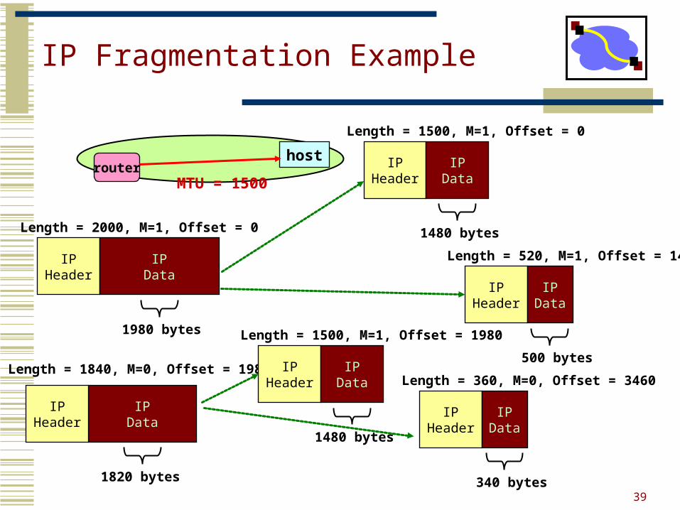
IP Fragmentation Example
IPHeader
IPData
Length = 2000, M=1, Offset = 0
1980 bytes
IPData
IPHeader
Length = 1840, M=0, Offset = 1980
1820 bytes
hostrouter
MTU = 1500
IPHeader
IPData
Length = 1500, M=1, Offset = 0
1480 bytes
IPHeader
IPData
Length = 520, M=1, Offset = 1480
500 bytesIP
HeaderIP
Data
Length = 1500, M=1, Offset = 1980
1480 bytes
IPHeader
IPData
Length = 360, M=0, Offset = 3460
340 bytes

40
Important Concepts
• Base-level protocol (IP) provides minimal service level• Allows highly decentralized implementation• Each step involves determining next hop• Most of the work at the endpoints
• ICMP provides low-level error reporting
• IP forwarding global addressing, alternatives, lookup tables
• IP addressing hierarchical, CIDR• IP service best effort, simplicity of routers• IP packets header fields, fragmentation, ICMP
41
Distance-Vector Routing
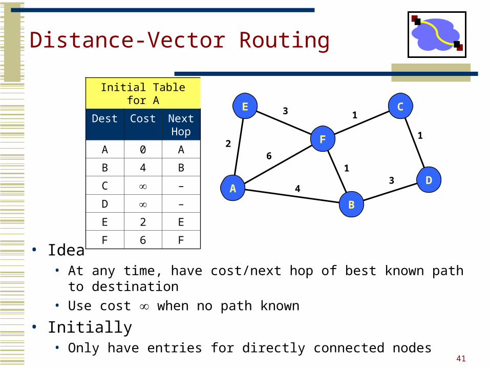
• Idea• At any time, have cost/next hop of best known path to destination• Use cost when no path known
• Initially• Only have entries for directly connected nodes
A
E
F
C
D
B
2
3
6
4
1
1
1
3
Initial Table for A
Dest Cost Next Hop
A 0 A
B 4 B
C –
D –
E 2 E
F 6 F
42
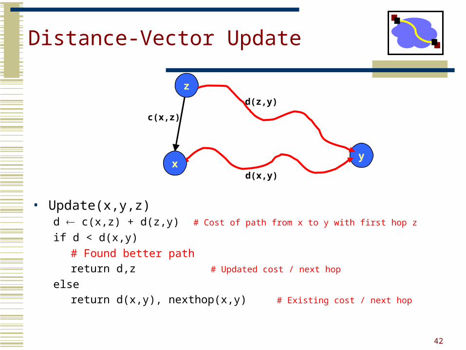
Distance-Vector Update
• Update(x,y,z)d c(x,z) + d(z,y) # Cost of path from x to y with first hop z
if d < d(x,y)
# Found better path
return d,z # Updated cost / next hop
else
return d(x,y), nexthop(x,y) # Existing cost / next hop
x
z
y
c(x,z)
d(z,y)
d(x,y)
43
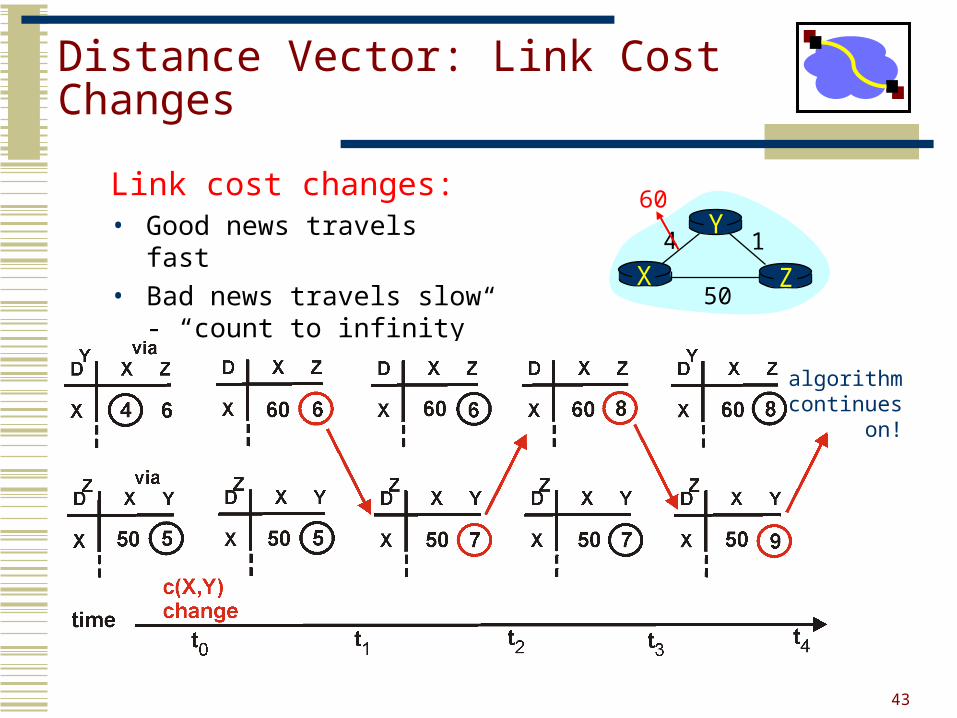
Distance Vector: Link Cost Changes
Link cost changes:• Good news travels fast • Bad news travels slow -
“count to infinity” problem!X Z
14
50
Y60
algorithmcontinues
on!
44
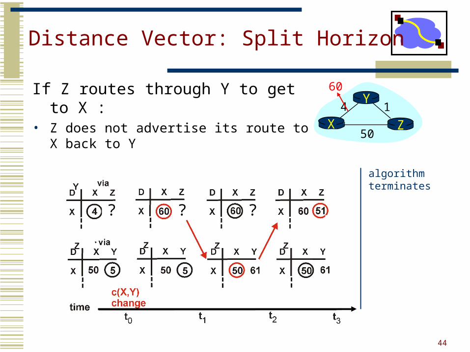
Distance Vector: Split Horizon
If Z routes through Y to get to X :• Z does not advertise its route to X back to Y
algorithmterminates
X Z14
50
Y60
? ? ?
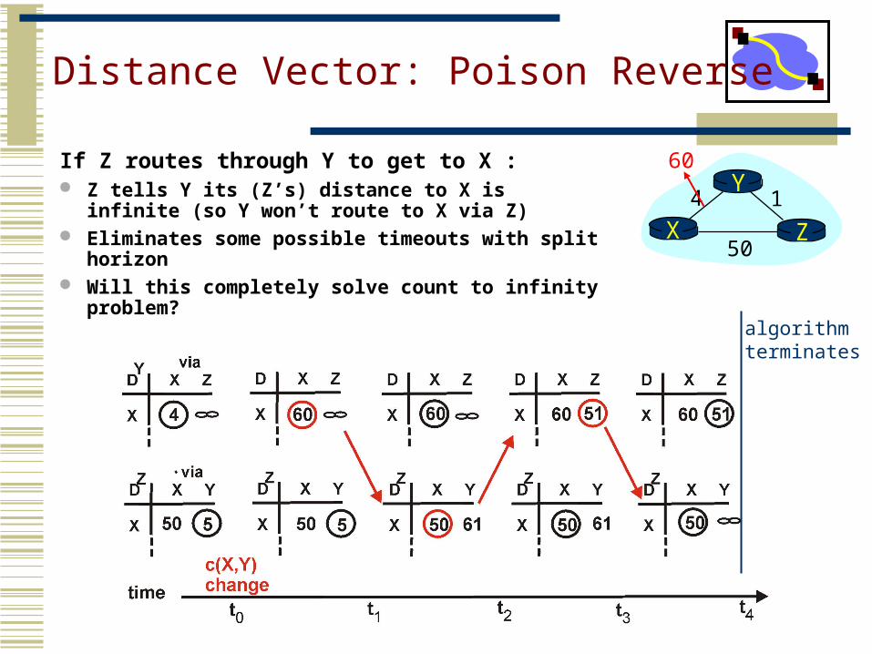
Distance Vector: Poison Reverse
If Z routes through Y to get to X : Z tells Y its (Z’s) distance to X is infinite (so Y won’t
route to X via Z) Eliminates some possible timeouts with split horizon Will this completely solve count to infinity problem?
X Z14
50
Y60
algorithmterminates

Poison Reverse Failures
• Iterations don’t converge
• “Count to infinity”
• Solution• Make “infinity” smaller
• What is upper bound on maximum path length?
Table for A
Dst Cst Hop
C 7 F
Table for B
Dst Cst Hop
C 8 A
Table for F
Dst Cst Hop
C 1 C
Table for F
Dst Cst Hop
C –
Table for A
Dst Cst Hop
C –
ForcedUpdate
Table for B
Dst Cst Hop
C 14 A
ForcedUpdate
F C6
1
1
1
BD
A
4
Table for D
Dst Cst Hop
C 9 B
ForcedUpdate
Table for A
Dst Cst Hop
C 13 D
BetterRoute
Table for D
Dst Cst Hop
C 15 B
Table for A
Dst Cst Hop
C 19 D
ForcedUpdate
•••
ForcedUpdate
47
Link State Protocol Concept
• Every node gets complete copy of graph• Every node “floods” network with data about its
outgoing links
• Every node computes routes to every other node• Using single-source, shortest-path algorithm
• Process performed whenever needed• When connections die / reappear
48
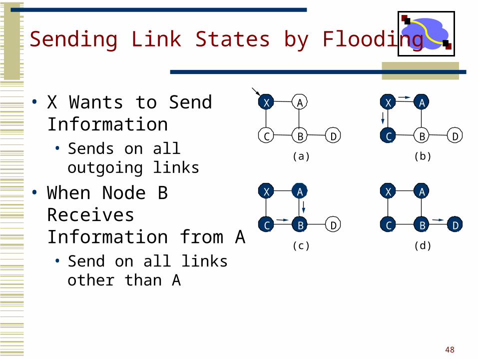
Sending Link States by Flooding
• X Wants to Send Information• Sends on all outgoing
links
• When Node B Receives Information from A• Send on all links other
than A
X A
C B D
(a)
X A
C B D
(b)
X A
C B D
(c)
X A
C B D
(d)

49
Comparison of LS and DV Algorithms
Message complexity• LS: with n nodes, E links, O(nE)
messages• DV: exchange between
neighbors only O(E)
Speed of Convergence• LS: Complex computation
• But…can forward before computation
• may have oscillations• DV: convergence time varies
• may be routing loops• count-to-infinity problem• (faster with triggered
updates)
Space requirements:• LS maintains entire topology• DV maintains only neighbor
state
Routing Hierarchies
• Flat routing doesn’t scale• Storage Each node cannot be expected to store
routes to every destination (or destination network)• Convergence times increase• Communication Total message count increases
• Key observation• Need less information with increasing distance to
destination• Need lower diameters networks
• Solution: area hierarchy
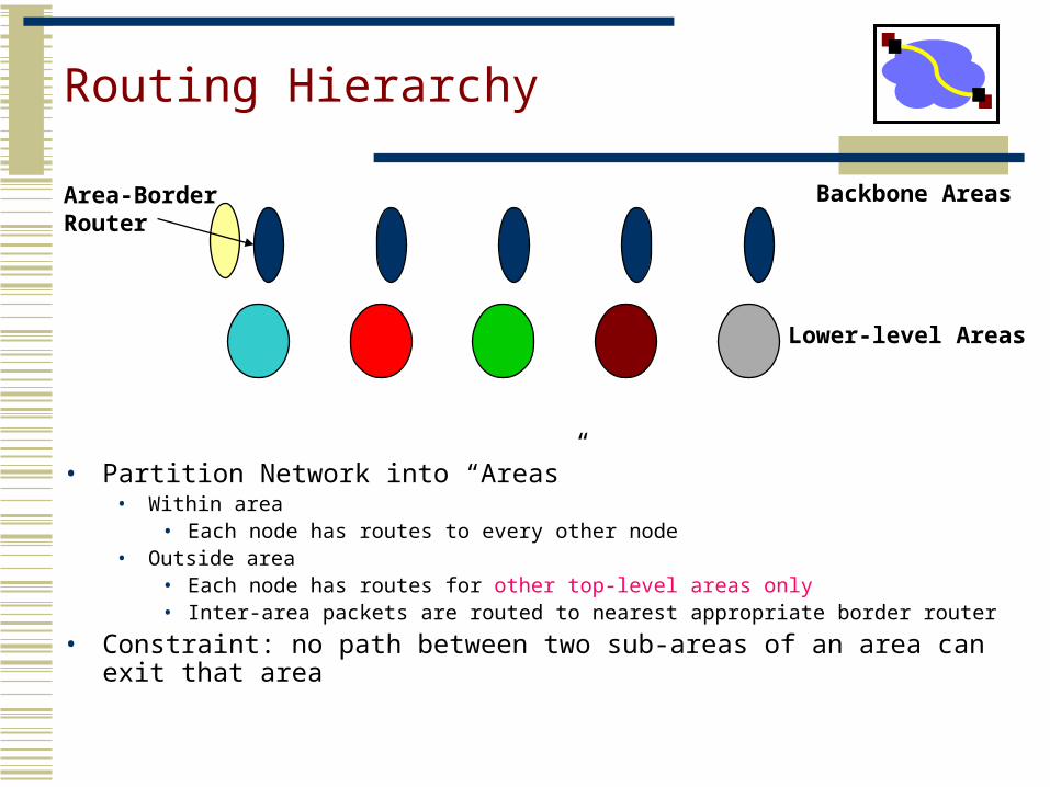
Routing Hierarchy
• Partition Network into “Areas”• Within area
• Each node has routes to every other node• Outside area
• Each node has routes for other top-level areas only• Inter-area packets are routed to nearest appropriate border router
• Constraint: no path between two sub-areas of an area can exit that area
Backbone Areas
Lower-level Areas
Area-BorderRouter
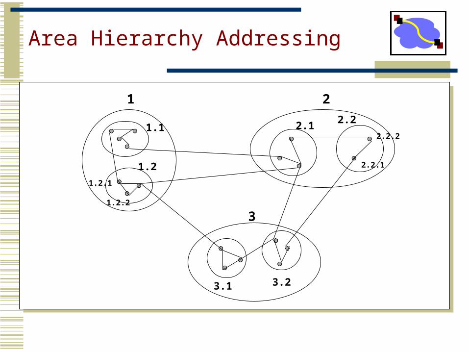
Area Hierarchy Addressing
1 2
3
1.1
1.2
2.12.2
3.1 3.2
2.2.1
2.2.2
1.2.1
1.2.2
53
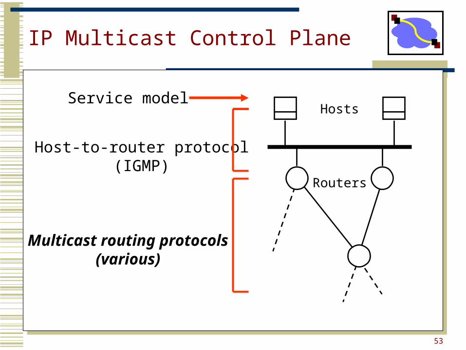
IP Multicast Control Plane
Hosts
Routers
Service model
Host-to-router protocol(IGMP)
Multicast routing protocols(various)
54
IP Multicast Service Model (rfc1112)
• Each group identified by a single IP address• Groups may be of any size• Members of groups may be located anywhere in the
Internet• Members of groups can join and leave at will• Senders need not be members• Group membership not known explicitly • Analogy:
• Each multicast address is like a radio frequency, on which anyone can transmit, and to which anyone can tune-in.
55
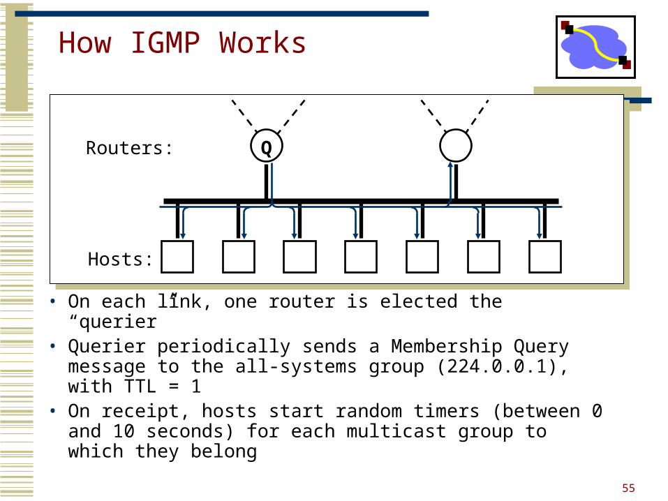
How IGMP Works
• On each link, one router is elected the “querier”• Querier periodically sends a Membership Query message to the
all-systems group (224.0.0.1), with TTL = 1• On receipt, hosts start random timers (between 0 and 10
seconds) for each multicast group to which they belong
QRouters:
Hosts:
56
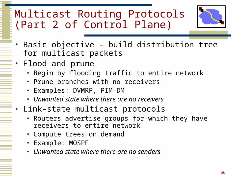
Multicast Routing Protocols(Part 2 of Control Plane)
• Basic objective – build distribution tree for multicast packets
• Flood and prune• Begin by flooding traffic to entire network• Prune branches with no receivers• Examples: DVMRP, PIM-DM• Unwanted state where there are no receivers
• Link-state multicast protocols• Routers advertise groups for which they have receivers to entire
network• Compute trees on demand• Example: MOSPF• Unwanted state where there are no senders

10/4/07 Lecture #11: Inter-Domain Routing 57
BGP - Border Gateway Protocol
• Covered next week
57
9-26-06 Lecture 9: IP Packets 58
Internet
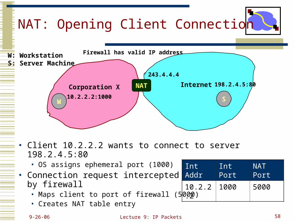
NAT: Opening Client Connection
• Client 10.2.2.2 wants to connect to server 198.2.4.5:80• OS assigns ephemeral port (1000)
• Connection request intercepted by firewall• Maps client to port of firewall (5000)• Creates NAT table entry
Corporation X
W
NAT
W: WorkstationS: Server Machine
10.2.2.2:1000 S
198.2.4.5:80
243.4.4.4
Int Addr Int Port NAT Port
10.2.2.2 1000 5000
Firewall has valid IP address
9-26-06 Lecture 9: IP Packets 59
Internet
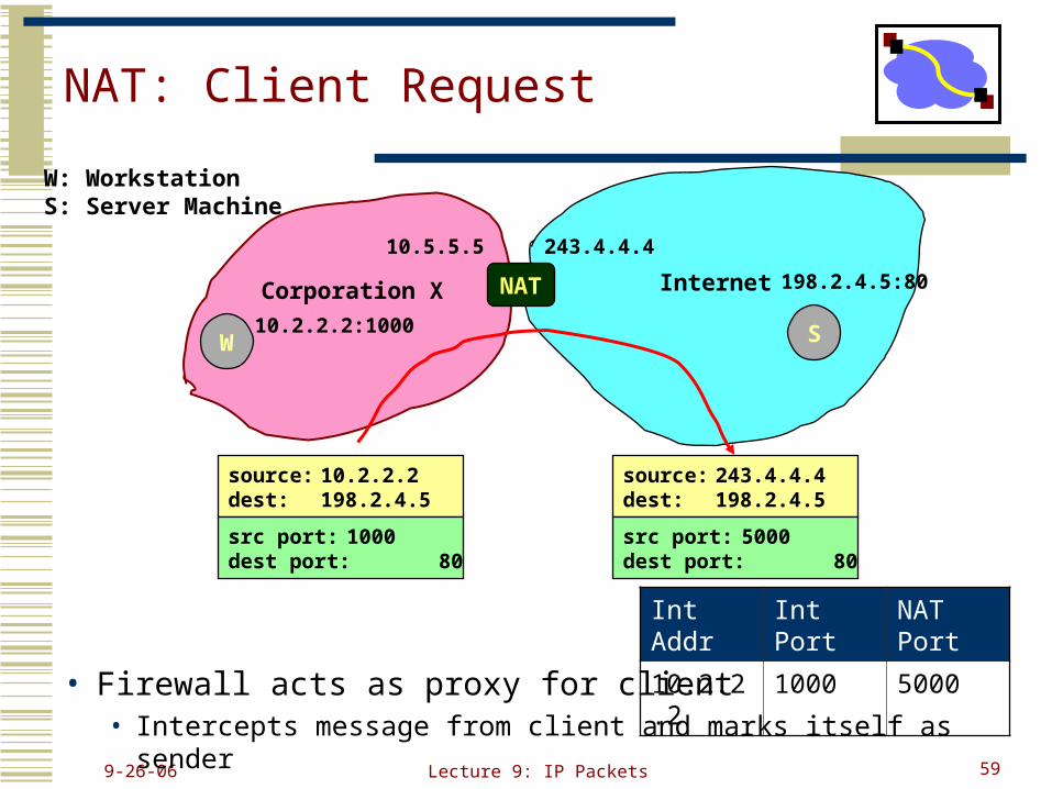
NAT: Client Request
• Firewall acts as proxy for client• Intercepts message from client and marks itself as sender
Corporation X
W
NAT
W: WorkstationS: Server Machine
10.2.2.2:1000 S
198.2.4.5:80
243.4.4.410.5.5.5
source: 10.2.2.2dest: 198.2.4.5
src port: 1000dest port: 80
source: 243.4.4.4dest: 198.2.4.5
src port: 5000dest port: 80
Int Addr Int Port NAT Port
10.2.2.2 1000 5000
9-26-06 Lecture 9: IP Packets 60
Internet
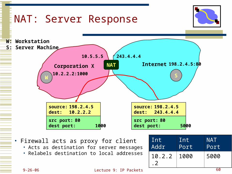
NAT: Server Response
• Firewall acts as proxy for client• Acts as destination for server messages• Relabels destination to local addresses
Corporation X
W
NAT
W: WorkstationS: Server Machine
10.2.2.2:1000 S
198.2.4.5:80
243.4.4.410.5.5.5
source: 198.2.4.5dest: 243.4.4.4
src port: 80dest port: 5000
source: 198.2.4.5dest: 10.2.2.2
src port: 80dest port: 1000
Int Addr Int Port NAT Port
10.2.2.2 1000 5000
9-26-06 Lecture 9: IP Packets 61
Internet
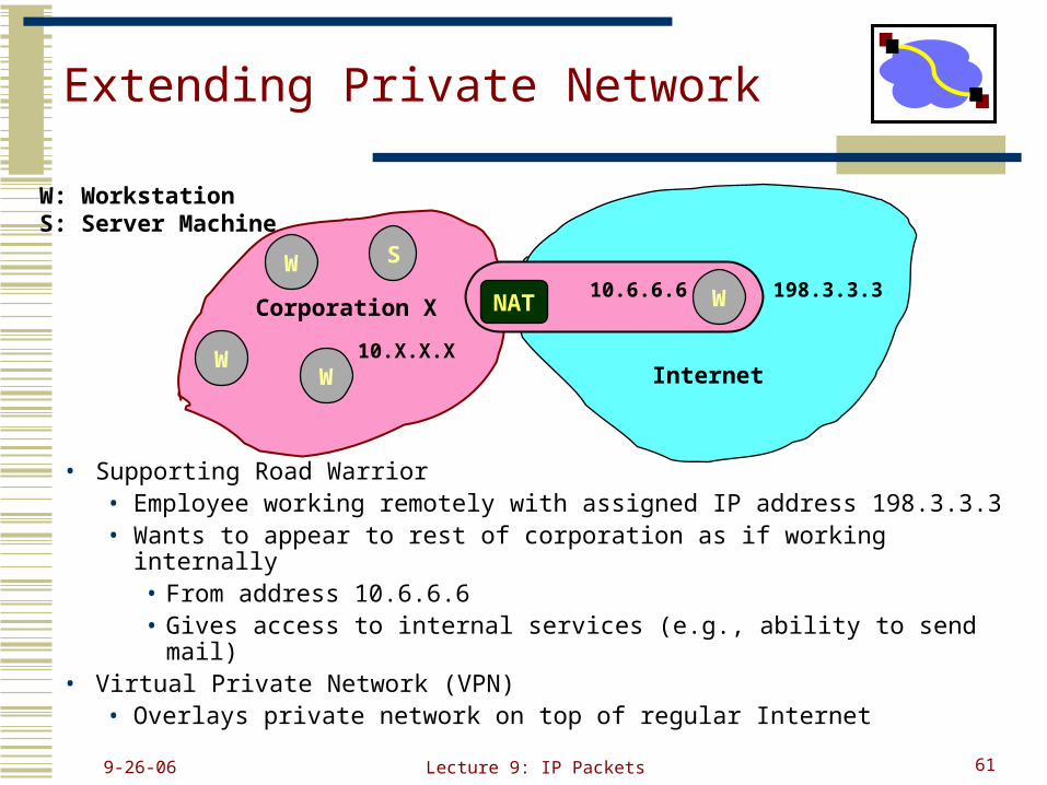
Extending Private Network
• Supporting Road Warrior• Employee working remotely with assigned IP address 198.3.3.3• Wants to appear to rest of corporation as if working internally
• From address 10.6.6.6• Gives access to internal services (e.g., ability to send mail)
• Virtual Private Network (VPN)• Overlays private network on top of regular Internet
Corporation X
W
W
W
S
W: WorkstationS: Server Machine
198.3.3.310.6.6.6
10.X.X.X
WNAT
62
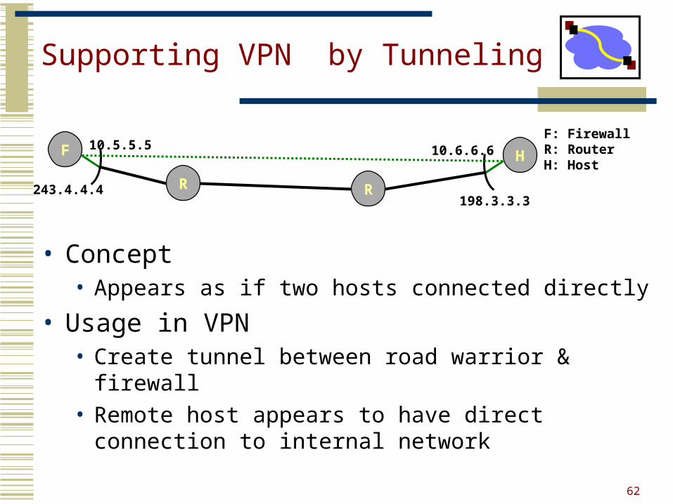
Supporting VPN by Tunneling
• Concept• Appears as if two hosts connected directly
• Usage in VPN• Create tunnel between road warrior & firewall• Remote host appears to have direct connection to
internal network
HF
R R198.3.3.3
243.4.4.4
10.5.5.5 10.6.6.6F: FirewallR: RouterH: Host
63
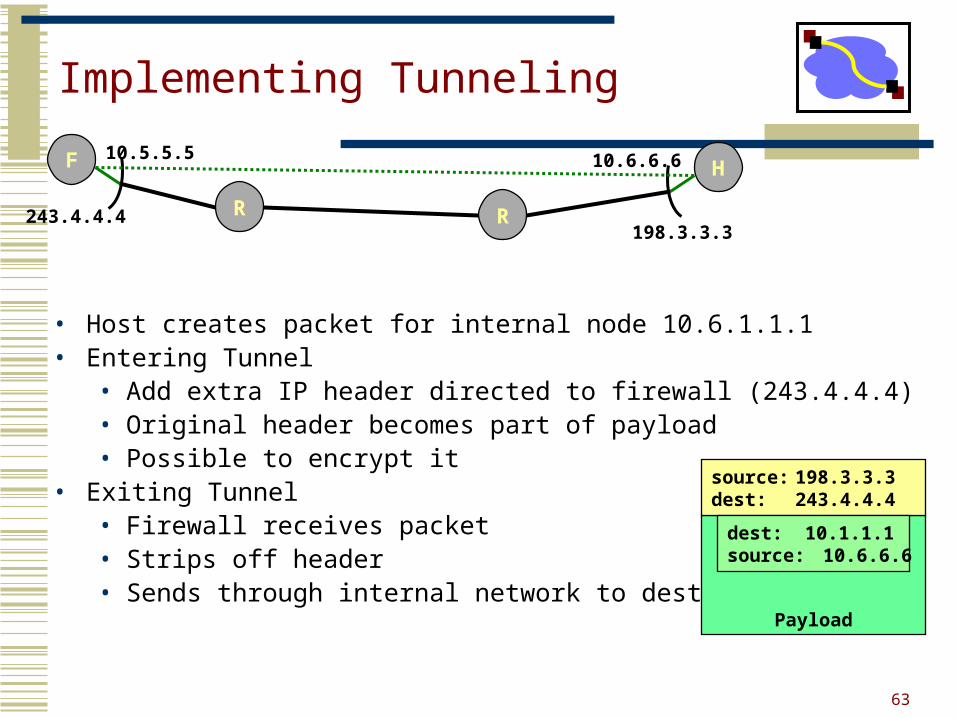
Implementing Tunneling
• Host creates packet for internal node 10.6.1.1.1 • Entering Tunnel
• Add extra IP header directed to firewall (243.4.4.4)• Original header becomes part of payload• Possible to encrypt it
• Exiting Tunnel• Firewall receives packet• Strips off header• Sends through internal network to destination
HF
R R198.3.3.3
243.4.4.4
10.5.5.5 10.6.6.6
Payload
source: 198.3.3.3dest: 243.4.4.4
dest: 10.1.1.1source: 10.6.6.6

64
Virtual Circuit IDs/Switching:Label (“tag”) Swapping
• Global VC ID allocation -- ICK! Solution: Per-link uniqueness. Change VCI each hop.
Input Port Input VCI Output Port Output VCI R1: 1 5 3 9 R2: 2 9 4 2 R4: 1 2 3 5
A
B
R2
R1
R3
R4 Dst
1
2
3
4
3
3
3
1
1
1
2
2
4
4
4
2

9-21-06 Lecture 8: Bridging/Addressing/Forwarding 66
Source Routing Example
Receiver
Packet
R1, R2, R3, R
Sender
2
34
1
2
34
1
2
34
1
R2
R3
R1
R2, R3, R
R3, R
R
9-21-06 Lecture 8: Bridging/Addressing/Forwarding 67
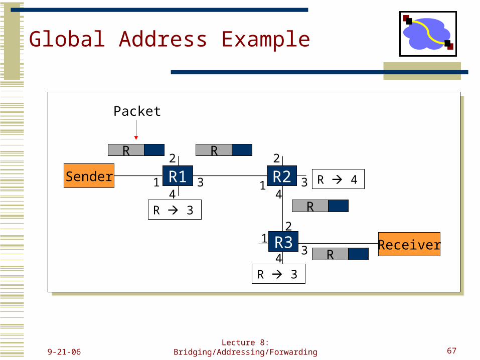
Global Address Example
Receiver
Packet
R
Sender
2
34
1
2
34
1
2
34
1
R2
R3
R1
R
RR 3
R 4
R 3
R

9-20-07 Lecture 7: Addressing/Forwarding 68
Comparison
Source Routing Global Addresses
Header Size Worst OK – Large address
Router Table Size NoneNumber of hosts
(prefixes)
Forward Overhead BestPrefix matching
(Worst)
Virtual Circuits
Best
Number of circuits
Pretty Good
Setup Overhead None None
Error Recovery Tell all hosts Tell all routers
Connection Setup
Tell all routers and Tear down circuit
and re-route
68
69
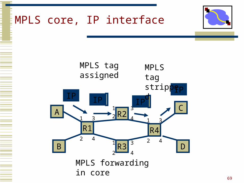
MPLS core, IP interface
A
B
R2
R1
R3
R4
C1
2
3
4
3
3
3
1
1
1
2
2
4
4
4
2
D
IP IP
MPLS tag assigned
IP
IP
MPLS forwarding in core
MPLS tag stripped

70
Take Home Points
• Costs/benefits/goals of virtual circuits• Cell switching (ATM)
• Fixed-size pkts: Fast hardware• Packet size picked for low voice jitter. Understand trade-offs.• Beware packet shredder effect (drop entire pkt)
• Tag/label swapping• Basis for most VCs. • Makes label assignment link-local. Understand mechanism.
• MPLS - IP meets virtual circuits• MPLS tunnels used for VPNs, traffic engineering, reduced core
routing table sizes
Outline
• Switching and Multiplexing• Link-Layer• Routing-Layer• Physical-Layer
• Encodings
71
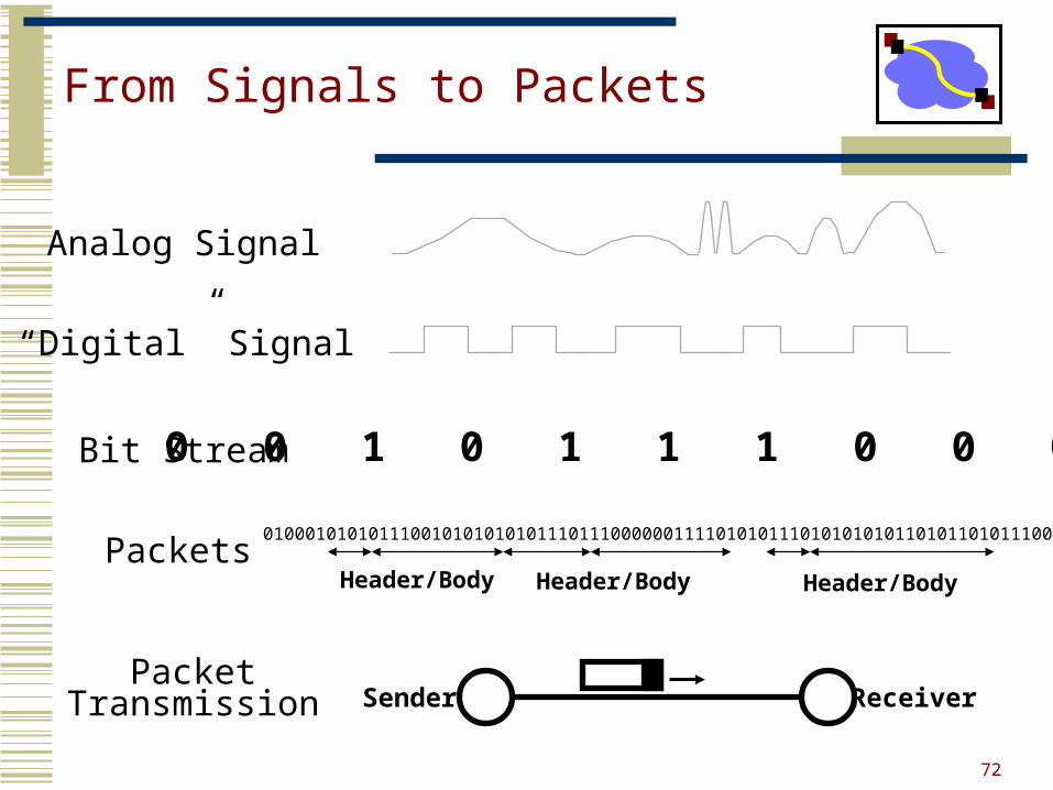
From Signals to Packets
Analog Signal
“Digital” Signal
Bit Stream 0 0 1 0 1 1 1 0 0 0 1
Packets0100010101011100101010101011101110000001111010101110101010101101011010111001
Header/Body Header/Body Header/Body
ReceiverSenderPacket
Transmission
72
Encoding
• We use two discrete signals, high and low, to encode 0 and 1
• The transmission is synchronous, i.e., there is a clock used to sample the signal• In general, the duration of one bit is equal to one or two
clock ticks
73

Non-Return to Zero (NRZ)
• 1 high signal; 0 low signal• Long sequences of 1’s or 0’s can cause problems:
• Sensitive to clock skew, i.e. hard to recover clock• Difficult to interpret 0’s and 1’s
74
V 0
.85
-.85
0 0 0 11 0 1 0 1
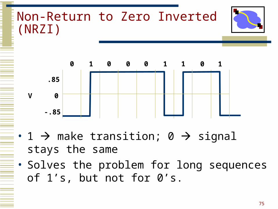
Non-Return to Zero Inverted (NRZI)
• 1 make transition; 0 signal stays the same• Solves the problem for long sequences of 1’s, but
not for 0’s.
75
V 0
.85
-.85
0 0 0 11 0 1 0 1
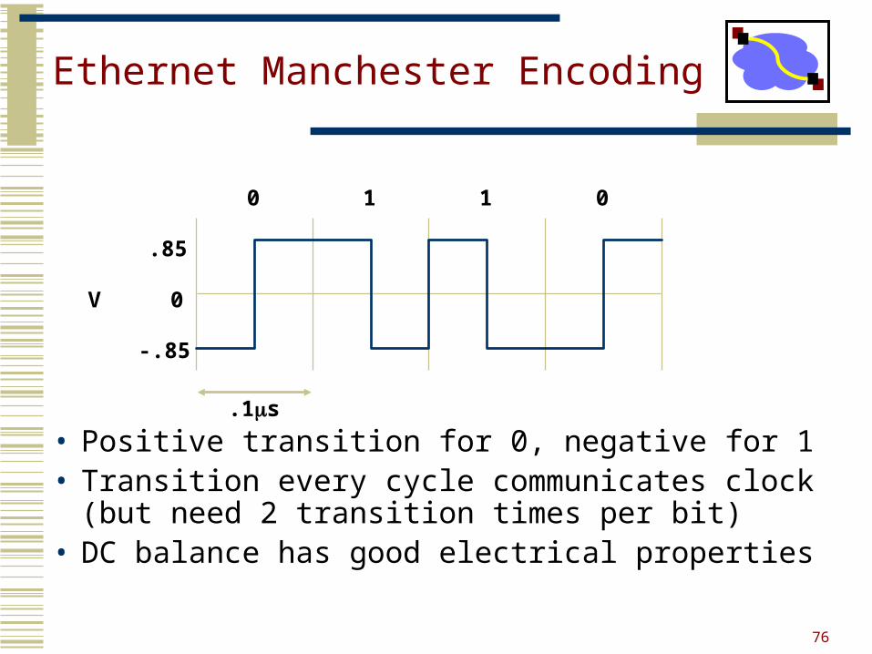
Ethernet Manchester Encoding
• Positive transition for 0, negative for 1• Transition every cycle communicates clock (but
need 2 transition times per bit)• DC balance has good electrical properties
76
V 0
.85
-.85
0 1 1 0
.1s
4B/5B Encoding
• Data coded as symbols of 5 line bits 4 data bits, so 100 Mbps uses 125 MHz.• Uses less frequency space than Manchester encoding
• Uses NRI to encode the 5 code bits• Each valid symbol has at least two 1s: get dense
transitions.• 16 data symbols, 8 control symbols
• Data symbols: 4 data bits• Control symbols: idle, begin frame, etc.
• Example: FDDI.
77

Framing
• A link layer function, defining which bits have which function.
• Minimal functionality: mark the beginning and end of packets (or frames).
• Some techniques:• out of band delimiters (e.g. FDDI 4B/5B control
symbols)• frame delimiter characters with character stuffing• frame delimiter codes with bit stuffing• synchronous transmission (e.g. SONET)
78
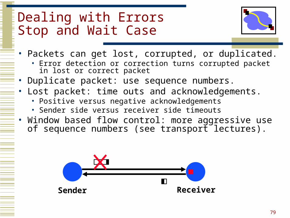
Dealing with ErrorsStop and Wait Case
• Packets can get lost, corrupted, or duplicated. • Error detection or correction turns corrupted packet in lost or
correct packet• Duplicate packet: use sequence numbers.• Lost packet: time outs and acknowledgements.
• Positive versus negative acknowledgements• Sender side versus receiver side timeouts
• Window based flow control: more aggressive use of sequence numbers (see transport lectures).
79
Sender Receiver