144 MH Z B AND RANSCEIVER FT-2600M - RadioManual · 144 MH Z B AND FM T RANSCEIVER FT-2600M O PERA...
62
144 MHZ BAND FM TRANSCEIVER FT-2600M OPERATING MANUAL VERTEX STANDARD CO., LTD. 4-8-8 Nakameguro, Meguro-Ku, Tokyo 153-8644, Japan VERTEX STANDARD US Headquarters 17210 Edwards Rd., Cerritos, CA 90703, U.S.A. International Division 8350 N.W. 52nd Terrace, Suite 201, Miami, FL 33166, U.S.A. YAESU EUROPE B.V. P.O. Box 75525, 1118 ZN Schiphol, The Netherlands YAESU UK LTD. Unit 12, Sun Valley Business Park, Winnall Close Winchester, Hampshire, SO23 0LB, U.K. VERTEX STANDARD HK LTD. Unit 5, 20/F., Seaview Centre, 139-141 Hoi Bun Road, Kwun Tong, Kowloon, Hong Kong
Transcript of 144 MH Z B AND RANSCEIVER FT-2600M - RadioManual · 144 MH Z B AND FM T RANSCEIVER FT-2600M O PERA...

144 MHZ BAND FM TRANSCEIVER
FT-2600MOPERATING MANUAL
VERTEX STANDARD CO., LTD.4-8-8 Nakameguro, Meguro-Ku, Tokyo 153-8644, Japan
VERTEX STANDARDUS Headquarters17210 Edwards Rd., Cerritos, CA 90703, U.S.A.International Division8350 N.W. 52nd Terrace, Suite 201, Miami, FL 33166, U.S.A.
YAESU EUROPE B.V.P.O. Box 75525, 1118 ZN Schiphol, The Netherlands
YAESU UK LTD.Unit 12, Sun Valley Business Park, Winnall CloseWinchester, Hampshire, SO23 0LB, U.K.
VERTEX STANDARD HK LTD.Unit 5, 20/F., Seaview Centre, 139-141 Hoi Bun Road,Kwun Tong, Kowloon, Hong Kong

Contents
General Description ............................ 1
Specifications ....................................... 2
Accessories & Options ......................... 3
Front Panel Controls and Switches ..... 4
Microphone Switches .......................... 6
Rear Panel Connectors ........................ 7
Installation ........................................... 8
Preliminary Inspection ...................................... 8
Installation Tips ............................................... 8Safety Information ........................................... 8
RF Field Exposure Information ......................... 9
Antenna Considerations .................................... 9
Mobile Installation ......................................... 11
Base Station Installation ................................. 13
Operation .......................................... 15
Basic Operation/Reception .............................. 15
Power ON/OFF .......................................... 15
Supply Voltage Display .............................. 15
Adjusting the Volume and Squelch............... 15 Lock Feature ............................................... 16
Keypad Beeper ........................................... 16
Display Brightness ...................................... 17
Tuning: The “Dial” (VFO) Mode ................. 17
Channel Step Selection ................................ 17
Direct Keypad Frequency Entry
(MH-36B6J Microphone) 18
Transmission ................................................. 19
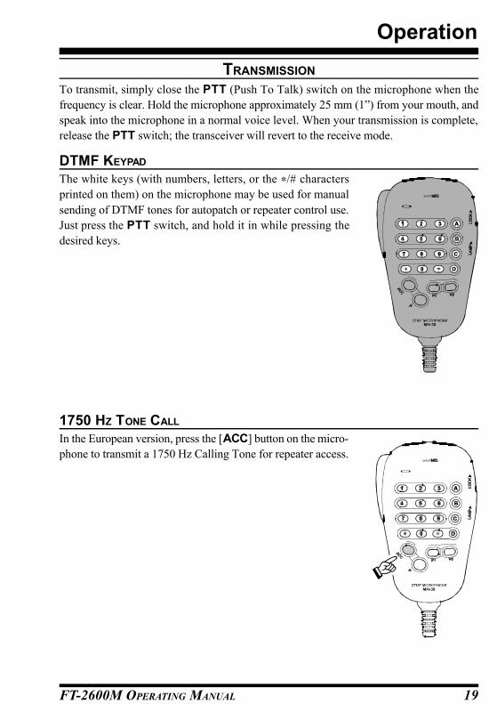
DTMF Keypad............................................ 19
1750 Hz Tone Call ...................................... 19
Power Output Setting .................................. 20
PTT Locking............................................... 20
Transmitter Thermal Protection Sensor ......... 21Repeater Operation ........................................ 22
Repeater Splits ............................................ 22
Tone Squelch Modes ...................................... 25
CTCSS
(Continuous Tone Coded Squelch System). 25
DCS (Digital Code Squelch) ........................ 25
CTCSS/DCS Selections using
Programmable Microphone Key... 27
CTCSS Tone Search Scanning ..................... 27
DCS Tone Search Scanning ......................... 28
DCS Code Inversion .................................... 28
CTCSS Bell Paging ..................................... 29
DTMF Autodialer Operation ........................... 30
Memory System Operation ............... 32
Memory Storage ............................................ 32
To Append an Alpha-Numeric
Label to a Memory: ............ 32
Recalling Memories ....................................... 33
Memory Recall from MH-36B6J Microphone .... 33
To Turn on the Alpha-Numeric Memory Name Display: ..... 33
Home Channel Memory ................................. 34
Memory Offset Tuning ................................... 34
Memory-Only Mode ...................................... 35
Deleting Memories ......................................... 35
Scanning ............................................ 36
Basic Scanner Operation ................................. 36
Scan-Resume Options .................................... 36
Memory Skip Scanning (MR Mode)................ 37
Temporary Memory Skip ............................... 37
Programmable Band-Scan Limits .................... 38Smart Search Operation .................................. 39
Priority Channel Monitoring ........................... 40
Priority Revert Mode ...................................... 41
ARTSTM: Auto Range Transpond System ...... 42
ARTS Basic Operation ................................... 42
ARTS Modes ................................................. 43
CW ID (Morse Identifier) Set up ..................... 43
Packet Operation .............................. 44
Miscellaneous Settings ...................... 45
Time-Out Timer ............................................. 45
Automatic Power-Off ..................................... 45
FM Bandwidth & Mic Gain Control ................ 46
Programmable Microphone Keys (ACC/P1/P2) 47
Resetting the CPU ............................. 48
Reset all MENU settings: .................................. 48
CPU master reset for all memories
and MENU settings: ..... 48
Transceiver Cloning .......................... 49
Menu System ..................................... 50
Menu Selection Summary ............................... 50
Menu Selection Details ................................... 51

FT-2600M OPERATING MANUAL 1
General Description
The FT-2600M is a deluxe, compact FM mobile transceiver providing high power output
and outstanding receiver performance for the 144 MHz band. Included in the FT-2600M’s
feature complement are:
m 60 Watts of power output, with selection of four power levels for every operating
situation.
m Expanded receiver coverage: 134-174 MHz.
m Keyboard entry of operating frequencies from the microphone.
m Excellent protection from receiver intermodulation distortion, thanks to Yaesu’s re-
nowned Advanced Track Tuning front end.
m Outstanding packet radio capability at 1200 or 9600 bps with easy interface via a
dedicated rear-panel jack.
m 175 memories which can store repeater shifts, odd repeater shifts, CTCSS/DCS tones,
and 8-character Alpha-Numeric labels for easy channel recognition.
m Built-in CTCSS and DCS Encoder/Decoder circuits.
m The Smart Search™ feature, which automatically sweeps a band and loads active fre-
quencies into dedicated memory banks, is ideal for identifying active repeaters when
visiting a city for the first time.
m Yaesu’s exclusive ARTS™ (Auto-Range Transponder System), which alerts the opera-
tor when an “out-of-range” condition exists with another ARTS™- equipped station.
This feature is especially valuable during search-and-rescue operations with hand-
held units.
m Extensive MENU system, which allows customization of a number of transceiver per-
formance characteristics.
m The Yaesu-exclusive multi-function LCD display.
Additional features include a transmit Time-Out-Timer (TOT), Automatic Power-Off (APO),
Automatic Repeater Shift (ARS), plus provision for reduction of the TX deviation in areas
of high channel congestion. And an all-new S-Meter Squelch circuit allows the owner to
set the squelch to open at a programmable setting of the S-Meter, thus reducing guesswork
in setting the squelch threshold.
Congratulations on your purchase of the FT-2600M! Whether this is your first rig, or if
Yaesu equipment is already the backbone of your station, the Yaesu organization is com-
mitted to ensuring your enjoyment of this high-performance transceiver, which should pro-
vide you with many years of satisfying operation. Yaesu’s dealer network and technical
support personnel stand behind every product we sell, and we invite you to contact us
should you require technical advice or assistance.
We recommend that you read this manual in its entirety prior to installing the FT-2600M,
so that you fully understand the capabilities of your new transceiver.

FT-2600M OPERATING MANUAL2
GeneralFrequency Range: Tx: 144-146 or 144-148 MHz
Rx: 144-146 MHz or 134-174 MHz
Channel Steps: 5/10/12.5/15/20/25/50 kHz
Frequency Stability: Better than ±10 ppm (-20º to +60º C)
Mode of Emission: F3 (G3E)
Antenna Impedance: 50 Ω, unbalanced
Supply voltage: 13.8 V DC (±10 %), negative ground
Current Consumption(typical): Rx: less than 1 A (max. signal)
less than 0.4 A (squelched)
Tx: 10 A (60 W)/ 6 A (25 W)/4 A (10 W)/3 A (5 W)
Operating Temperature Range: -20º to +60º C (-4º to +140º F)
Case Size (WHD): 160 x 40 x 160 mm (6.3” x 1.6” x 6.3”)
(W/o knobs/connectors)
Weight: 1.3 kg (2.9 lb.)
TransmitterOutput Power: 60W/25W/10W/5W
Modulation Type: Variable Reactance
Maximum Deviation: ±5 kHz /±2.5 kHz
Spurious Radiation: Better than –60 dB
Microphone Impedance: 2 kΩ
ReceiverCircuit Type: Double-Conversion Superheterodyne
Intermediate Frequencies: 21.7 MHz & 450 kHz
Sensitivity (for 12dB SINAD): Better than 0.2 µV @ 15 kHz bandwidth
Selectivity (-6/-60dB): 12 / 30 kHz or 10/24 kHz
IF Rejection: Better than 70 dB
Image Rejection: Better than 70 dB
Maximum AF Output: 3.5 W into 4 Ω @10 % THD
Specifications subject to change without notice or obligation.
Specifications guaranteed only within the amateur band.
Frequency range and repeater shift may vary according to local requirements and regula-
tions.
Specifications
FT-2600M OPERATING MANUAL 3
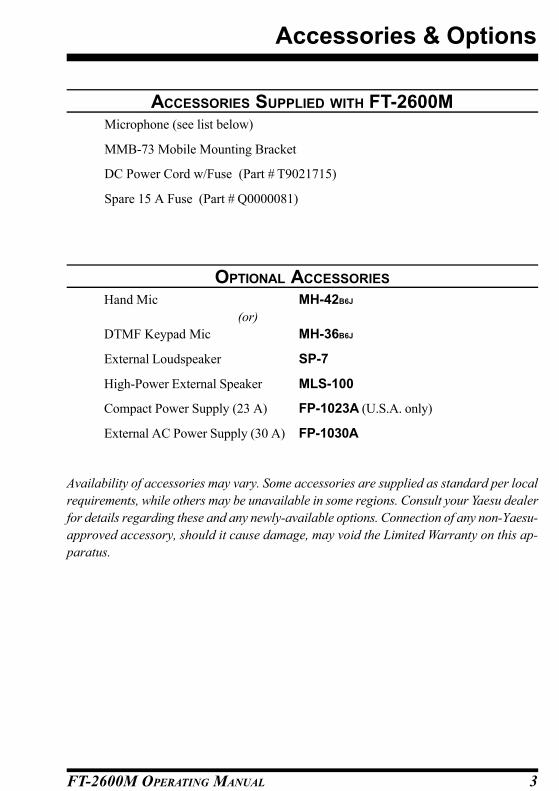
ACCESSORIES SUPPLIED WITH FT-2600MMicrophone (see list below)
MMB-73 Mobile Mounting Bracket
DC Power Cord w/Fuse (Part # T9021715)
Spare 15 A Fuse (Part # Q0000081)
OPTIONAL ACCESSORIES
Hand Mic MH-42B6J
(or)
DTMF Keypad Mic MH-36B6J
External Loudspeaker SP-7
High-Power External Speaker MLS-100
Compact Power Supply (23 A) FP-1023A (U.S.A. only)
External AC Power Supply (30 A) FP-1030A
Availability of accessories may vary. Some accessories are supplied as standard per local
requirements, while others may be unavailable in some regions. Consult your Yaesu dealer
for details regarding these and any newly-available options. Connection of any non-Yaesu-
approved accessory, should it cause damage, may void the Limited Warranty on this ap-
paratus.
Accessories & Options

FT-2600M OPERATING MANUAL4
(1) Power / VOL KnobTurn this control clockwise to turn the radio on and to increase the volume.
Counterclockwise rotation into the click-stop will turn the radio off.
(2) Microphone JackThis 6-contact modular jack accepts transmit audio, tone call (burst) or Dial / Memory
selection, and Scanning control from the microphone.
Pin 1: SW 2 (Multi-function switching)
Pin 2: Cloning
Pin 3: +9V
Pin 4: GND
Pin 5: Microphone Input
Pin 6: SW 1 (Multi-function switching)
(3) MHz (SET) KeyThis button allows tuning in 1-MHz steps (the MHz digits will blink on the display). If
receiving on a memory, pressing this button the first time activates the Memory Tune (MT)
mode, and pressing it again enables 1-MHz steps.
Press and hold this key for one second to activate the “Set” (MENU) Mode.
(4) REV (LOW) KeyDuring split-frequency operation, such as through a repeater, this button reverses the trans-
mit and receive frequencies.
Press and hold this key for one second to change the transmitter power output level.
The available power levels are:
HIGH (60W) ⇒ LOW1 (25W) ⇒ LOW2 (10W) ⇒ LOW3 (5W) ⇒ HIGH (60W). . .
Front Panel Controls and Switches
(1) (8) (9)
(2) (3) (4) (5) (6) (7)

FT-2600M OPERATING MANUAL 5
(5) A/N (DW) KeyWhile receiving on a memory, pressing this button toggles the display between indication
of the frequency and the channel’s Alpha/Numeric label.
Press and hold this key for one second to activate the Dual Watch feature, described in the
Operation chapter (“PRI” will be displayed on the LCD, indicating “Priority Channel”
monitoring).
(6) D/MR (MW) KeyThis button switches operation between the two main tuning modes: Dial and Memory
Recall.
Press and hold this key for one second to activate the Memory Storage mode.
(7) Main Dial KnobThis 20-position detented rotary switch is used for tuning, memory selection and most
function settings. Note that the microphone’s UP/DWN buttons duplicate the tuning func-
tions of the Main Dial.
(8) BUSY/TX IndicatorThis lamp glows green (during reception) when the channel is busy, and red during trans-
mission.
(9) DisplayThe main digits on the display may show operating frequency, memory name, and/or a
number of parameters during MENU configuration.
.
Front Panel Controls and Switches
LOW Power Selected
SKIP Active
SCAN Active
Continuous Tone Coded
Squelch System
Digital Code Squelch
Priority Channel
S - and Tx Power Meter Key Lock Active
Bell Alarm Active
Repeater Shift Direction
Frequency /
Message Area
Automatic Range Transponder
System

FT-2600M OPERATING MANUAL6
(10) PTT SwitchPress this switch to transmit, and release it to re-
ceive.
(11) KEYPADThe desired operating frequency may be entered di-
rectly from the keypad.
(12) DWN ButtonPress this button momentarily to tune downward by
one synthesizer step. Hold this button in for one
second to start scanning.
(13) UP ButtonPress this button momentarily to tune upward by
one synthesizer step. Hold this button in for one
second to start scanning.
(14) LOCK Switch Slide this switch upward to lock the microphone’s
buttons.
(15) LAMP Switch Slide this switch upward to activate the back-light-
ing for the microphone’s keys.
(16) ACC Button (TSRCH)This is one of three programmable-function keys
(ACC, P1, and P2) which may be used for control
of operating functions. The configuration of this key
is programmed via the MENU, and the default func-
tion is “Tone Search.”
(17) P Button (D/MR)This key allows selection of the Dial, Home Channel,
or Memory Recall tuning methods.
(18) P1 Button (SQL OFF)The default function for this key is “Monitor” (Squelch Off).
(19) P2 Button (SSRCH) The default function for this key is activation of the Smart Search™ feature.
Microphone Switches (MH-36B6J)
Note: DTMF keys may not be availaable on some transceiver versions. Microphone ap-
pearance may differ slightly from that shown in the drawing.
(12)
(19)
(15)
(14)
(10)
(11)
(16)
(17) (18)
(13)
(12)
(19)
(14)
(10)
(16)
(17) (18)
(13)
MH-36B6J
MH-42B6J
FT-2600M OPERATING MANUAL 7
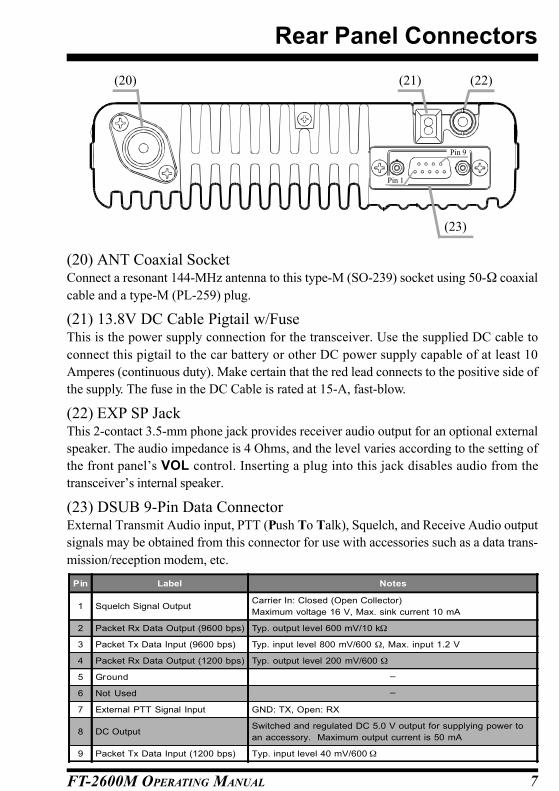
(20) ANT Coaxial SocketConnect a resonant 144-MHz antenna to this type-M (SO-239) socket using 50-Ω coaxial
cable and a type-M (PL-259) plug.
(21) 13.8V DC Cable Pigtail w/FuseThis is the power supply connection for the transceiver. Use the supplied DC cable to
connect this pigtail to the car battery or other DC power supply capable of at least 10
Amperes (continuous duty). Make certain that the red lead connects to the positive side of
the supply. The fuse in the DC Cable is rated at 15-A, fast-blow.
(22) EXP SP JackThis 2-contact 3.5-mm phone jack provides receiver audio output for an optional external
speaker. The audio impedance is 4 Ohms, and the level varies according to the setting of
the front panel’s VOL control. Inserting a plug into this jack disables audio from the
transceiver’s internal speaker.
(23) DSUB 9-Pin Data ConnectorExternal Transmit Audio input, PTT (Push To Talk), Squelch, and Receive Audio output
signals may be obtained from this connector for use with accessories such as a data trans-
mission/reception modem, etc.
(20) (22)(21)
(23)
Rear Panel Connectors
Pin Label Notes
1 Squelch Signal OutputCarrier In: Closed (Open Collector)
Maximum voltage 16 V, Max. sink current 10 mA
2 Packet Rx Data Output (9600 bps) Typ. output level 600 mV/10 kΩ
3 Packet Tx Data Input (9600 bps) Typ. input level 800 mV/600 Ω, Max. input 1.2 V
4 Packet Rx Data Output (1200 bps) Typ. output level 200 mV/600 Ω
5 Ground −
6 Not Used −
7 External PTT Signal Input GND: TX, Open: RX
8 DC OutputSwitched and regulated DC 5.0 V output for supplying power to
an accessory. Maximum output current is 50 mA
9 Packet Tx Data Input (1200 bps) Typ. input level 40 mV/600 Ω
Pin 9
Pin 1

FT-2600M OPERATING MANUAL8
This chapter describes the installation procedure for integrating the FT-2600M into a typi-
cal amateur radio station. It is presumed that you possess technical knowledge and concep-
tual understanding consistent with your status as a licensed radio amateur. Please take
some extra time to make certain that the important safety and technical requirements de-
tailed in this chapter are followed closely.
PRELIMINARY INSPECTION
Inspect the transceiver visually immediately upon opening the packing carton. Confirm
that all controls and switches work freely, and inspect the cabinet for any damage. Gently
shake the transceiver to verify that no internal components have been shaken loose due to
rough handling during shipping.
If any evidence of damage is discovered, document it thoroughly and contact the shipping
company (or your local dealer, if the unit was purchased over-the-counter) so as to get
instructions regarding the prompt resolution of the damage situation. Be certain to save the
shipping carton, especially if there are any punctures or other evidence of damage incurred
during shipping; if it is necessary to return the unit for service or replacement, use the
original packing materials but put the entire package inside another packing carton, so as
to preserve the evidence of shipping damage for insurance purposes.
INSTALLATION TIPS
To ensure long life of the components, be certain to provide adequate ventilation around
the cabinet of the FT-2600M.
Do not install the transceiver on top of another heat-generating device (such as a power
supply or amplifier), and do not place equipment, books, or papers on top of the FT-2600M.
Avoid heating vents and window locations that could expose the transceiver to excessive
direct sunlight, especially in hot climates. The FT-2600M should not be used in an envi-
ronment where the ambient temperature exceeds +60º C (140º F).
SAFETY INFORMATION
The FT-2600M is an electrical apparatus, as well as a generator of RF (Radio Frequency)
energy, and you should exercise all safety precautions as are appropriate for this type of
device. These safety tips apply to any device installed in a well-designed amateur radio
station.
r Do not allow unsupervised children to play in the vicinity of your transceiver or an-
tenna installation.
r Be certain to wrap any wire or cable splices thoroughly with insulating electrical tape,
to prevent short circuits.
Installation

FT-2600M OPERATING MANUAL 9
r Do not route cables or wires through door jambs or other locations where, through
wear and tear, they may become frayed and shorted to ground or to each other.
r Do not stand in front of a directional antenna while you are transmitting into that
antenna. Do not install a directional antenna in any location where humans or pets may
be walking in the main directional lobe of the antenna’s radiation pattern.
r In mobile installations, it is preferable to mount your antenna on top of the roof of the
vehicle, if feasible, so as to utilize the car body as a counterpoise for the antenna and
raise the radiation pattern as far away from passengers as possible.
r During vehicular operation when stopped (in a parking lot, for example), make it a
practice to switch to Low power if there are people walking nearby.
r Never wear dual-earmuff headphones while driving a vehicle.
RF FIELD EXPOSURE INFORMATION
This transceiver is capable of power output in excess of 50 Watts, so customers in the
United States may be required to demonstrate compliance with Federal Communications
Commission (FCC) regulations concerning maximum permissible exposure to radio fre-
quency energy. Compliance is based on the actual power output used, feedline loss, an-
tenna type and height, and other factors which can only be evaluated as a system.
Information regarding these regulations may be available from your Dealer, your local
radio club, from the FCC directly (press releases and other information can be found on the
FCC’s site on the World Wide Web at <http://www.fcc.gov>), or from the American Radio
Relay League, Inc. (225 Main St., Newington CT 06111 or <http://www.arrl.org>).
ANTENNA CONSIDERATIONS
The FT-2600M is designed for use with antennas presenting an impedance of near 50 Ω at
all operating frequencies. The antenna (or a 50 Ω dummy load) should be connected when-
ever the transceiver is turned on, to avoid damage that could otherwise result if transmis-
sion occurs accidentally without an antenna.
Ensure that your antenna is designed to handle 60 Watts of transmitter power. Some mag-
netic-mount mobile antennas, designed for use with hand-held transceivers, may not be
capable of this power level. Consult the antenna manufacturer’s specification sheet for
details.
Most all FM work is performed using vertical polarization. When installing a directional
antenna such as a Yagi or Quad, be certain to orient it so as to produce vertical polarization,
unless you are engaged in a special operating situation where horizontal polarization is
used.
Installation
FT-2600M OPERATING MANUAL10
Note that this transceiver is designed with wide frequency coverage in the VHF spectrum.
For general listening, you may wish to have a broadband antenna such as a discone avail-
able, as a directional antenna such as a Yagi will have degraded performance outside the 2-
meter Amateur band.
Excellent reference texts and computer software are available for the design and optimiza-
tion of VHF antennas. Your dealer should be able to assist you with all aspects of your
antenna installation requirements.
Use high-quality 50 Ω coaxial cable for the lead-in to your FT-2600M transceiver. All
efforts at providing an efficient antenna system will be wasted if poor quality, lossy coaxial
cable is used. Losses in coaxial lines increase as the frequency increases, so an 8-meter-
long (25’) coaxial line with 0.75 dB of loss at 28 MHz may have a loss of 1.8 dB or more
at 146 MHz; choose your coaxial cable carefully based on the installation location (mobile
vs. base) and the overall length of the cable required (for very short runs of cable in a
mobile installation, the smaller, more flexible cable types may be acceptable).
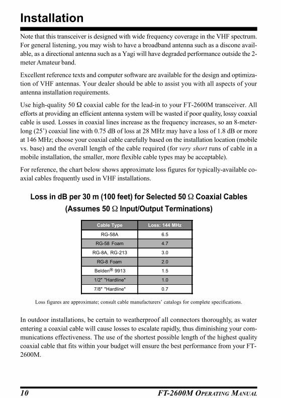
For reference, the chart below shows approximate loss figures for typically-available co-
axial cables frequently used in VHF installations.
Installation
Loss in dB per 30 m (100 feet) for Selected 50 Ω Coaxial Cables
(Assumes 50 Ω Input/Output Terminations)
Cable Type Loss: 144 MHz
RG-58A 6.5
RG-58 Foam 4.7
RG-8A, RG-213 3.0
RG-8 Foam 2.0
Belden 9913 1.5
1/2" "Hardline" 1.0
7/8" "Hardline" 0.7
Loss figures are approximate; consult cable manufacturers’ catalogs for complete specifications.
In outdoor installations, be certain to weatherproof all connectors thoroughly, as water
entering a coaxial cable will cause losses to escalate rapidly, thus diminishing your com-
munications effectiveness. The use of the shortest possible length of the highest quality
coaxial cable that fits within your budget will ensure the best performance from your FT-
2600M.
FT-2600M OPERATING MANUAL 11
Installation
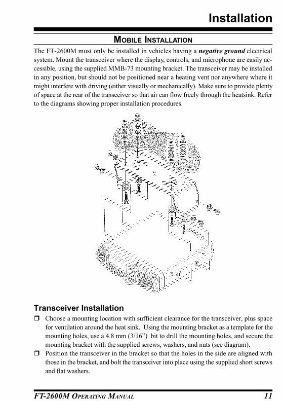
MOBILE INSTALLATION
The FT-2600M must only be installed in vehicles having a negative ground electrical
system. Mount the transceiver where the display, controls, and microphone are easily ac-
cessible, using the supplied MMB-73 mounting bracket. The transceiver may be installed
in any position, but should not be positioned near a heating vent nor anywhere where it
might interfere with driving (either visually or mechanically). Make sure to provide plenty
of space at the rear of the transceiver so that air can flow freely through the heatsink. Refer
to the diagrams showing proper installation procedures.
Transceiver Installation
r Choose a mounting location with sufficient clearance for the transceiver, plus space
for ventilation around the heat sink. Using the mounting bracket as a template for the
mounting holes, use a 4.8 mm (3/16”) bit to drill the mounting holes, and secure the
mounting bracket with the supplied screws, washers, and nuts (see diagram).
r Position the transceiver in the bracket so that the holes in the side are aligned with
those in the bracket, and bolt the transceiver into place using the supplied short screws
and flat washers.

FT-2600M OPERATING MANUAL12
Mobile Power Connections
To minimize voltage drop and avoid blowing the vehicle’s fuses, connect the supplied DC
power cable directly to the battery terminals. Do not attempt to defeat or bypass the DC
cable’s fuse—it is there to protect you, your transceiver, and your vehicle’s electrical sys-
tem.
Warning!
Never apply AC power to the power cable of the FT-2600M, nor DC voltage greater
than 15.2 Volts. When replacing the fuse, only use a 15-A fast-blow type. Failure to
observe these safety precautions will void the Limited Warranty on this product.
r Before connecting the transceiver, check the voltage at the battery terminals while
revving the engine. If the voltage exceeds 15 Volts, adjust the vehicle’s voltage regula-
tor before proceeding with installation.
r Connect the RED power cable lead to the POSITIVE (+) battery terminal, and the BLACK
power cable lead to the NEGATIVE (-) terminal. If you need to extend the power cable,
use #12 AWG or larger insulated, stranded copper wire. Solder the splice connections
carefully, and wrap the connections thoroughly with insulating electrical tape.
r Before connecting the cable to the transceiver, verify the voltage and polarity of the
voltage at the transceiver end of the DC cable using a DC voltmeter. Now connect the
transceiver to the DC cable.
Mobile Speakers
The optional SP-7 External Speaker includes its own swivel-type mounting bracket, and is
available from your Yaesu dealer.
Other external speakers may be used with the FT-2600M, if they present the specified 4-
Ω impedance and are capable of handling the 3.5 Watts of audio output supplied by the
FT-2600M.
Installation

FT-2600M OPERATING MANUAL 13
BASE STATION INSTALLATION
The FT-2600M is ideal for base station use as well as in mobile installations. The FT-
2600M is specifically designed to integrate into your station easily, using the information
to follow as a reference.
AC Power Supplies
Operation of the FT-2600M from an AC line requires a power source capable of providing
at least 10 Amps continuously at 13.8 Volts DC. The FP-1023A, FP-1025A, and FP-1030A
AC Power Supplies are available from your Yaesu dealer to satisfy these requirements.
Other well-regulated power supplies may be used, as well, if they meet the above voltage
and current specifications.
Use the DC power cable supplied with your transceiver for making power connections to the
power supply. Connect the RED power cable lead to the POSITIVE (+) power supply termi-
nal, and connect the BLACK power cable lead to the NEGATIVE (-) power supply terminal.
Packet Radio Terminal Node Controller (TNC)
The FT-2600M provides a convenient rear-panel DATA jack for easy connections to your
TNC. This connector is a standard Dsub 9-pin connector, widely available from electron-
ics parts suppliers.
The FT-2600M’s DATA jack connections are optimized for the data transmission and recep-
tion speed in use. In accordance with industry standards, the signal levels, impedances, and
bandwidths are significantly different on 9600 bps as opposed to 1200 bps. If your TNC does
not provide multiple lines to accommodate such optimization, you may still be able to utilize
your TNC, if it is designed for multiple-radio use, by connecting the TNC “Radio 1” port to
the 1200 bps lines on the FT-2600M, and the “Radio 2” port to the 9600 bps lines.
The pin connections of the DATA connector are shown below.
Installation
Pin Label Notes
1 Squelch Signal OutputCarrier In: Closed (Open Collector)
Maximum voltage 16 V, Max. sink current 10 mA
2 Packet Rx Data Output (9600 bps) Typ. output level 600 mV/10 kΩ
3 Packet Tx Data Input (9600 bps) Typ. input level 800 mV/600 Ω, Max. input 1.2 V
4 Packet Rx Data Output (1200 bps) Typ. output level 200 mV/600 Ω
5 Ground −
6 Not Used −
7 External PTT Signal Input GND: TX, Open: RX
8 DC OutputSwitched and regulated DC 5.0 V output for supplying power to
an accessory. Maximum output current is 50 mA
9 Packet Tx Data Input (1200 bps) Typ. input level 40 mV/600 Ω

FT-2600M OPERATING MANUAL14
Note that 9600 bps packet transmit-deviation adjustment is very critical to successful op-
eration, and can only be accomplished using a calibrated deviation meter (such as that
found on an FM Service Monitor used in a communications service center). In most cases,
the Packet Data Input level (set via a potentiometer inside the TNC) must be adjusted to
provide a deviation of ±2.75 kHz (±0.25 kHz). Check with your packet node’s sysop if you
have any questions about the appropriate deviation level for your network.
The setting of the 1200 bps Packet Data Input level is much less critical, and satisfactory
adjustment to the optimum (±2.5 ~ ±3.5 kHz) deviation can usually be done “by ear” by
adjusting the TNC’s 1200 bps TX Audio Level potentiometer so that the outgoing packets
(as monitored on a separate VHF or UHF receiver) are approximately the same level as
(A) the DTMF tones or (B) the 1750 Hz Burst tone produced by the MH-36B6J or MH-42B6J
microphone.
Typical connections to a TNC are shown below.
Installation
Finally, note that MENU #18 (“PCKT”) allows you to enable or disable the microphone
during packet operation. Normally, the default setting (“Microphone Disabled during Packet
TX”) is appropriate; when the microprocessor detects PTT input from the Data connector,
the microphone will be disabled.

FT-2600M OPERATING MANUAL 15
Operation
BASIC OPERATION/RECEPTION
POWER ON/OFF
Turn the Power / VOL Knob clockwise to turn on the radio.
The start-up channel will be the same one on which you were operating when the radio was
last turned off.
SUPPLY VOLTAGE DISPLAY
When you turn on the radio, the current DC supply voltage will be indicated on the display
for one second. After this interval, the display will resume its normal indication of the
operating frequency.
To view the supply voltage at any time during operation, use the following procedure:
(1) Press and hold the [MHz] key for one second to activate the “Set” (MENU) mode, then
rotate the Main Dial knob to select “0 9 DC IN .”
(2) Press the [MHz] key momentarily to display the current DC supply voltage on the
LCD.
(3) Press and hold in the [MHz] key for one second to exit to normal operation.
ADJUSTING THE VOLUME AND SQUELCH
Rotate the VOL control to adjust the receiver volume. Clockwise rotation increases the
audio output level.
The Squelch system is designed to keep the receiver quiet until a signal is received. The
Squelch should be adjusted to the point where the background noise is just silenced; any
“higher” setting will reduce the receiver’s sensitivity to weak signals.
To adjust the setting of the Squelch system:
(1) Rotate the Main Dial to select a clear frequency (where no signals are present).
(2) Press and hold in the [MHz] key for one second, then rotate the Main Dial knob to
select “2 8 SQL.”
(3) Press the [MHz] key momentarily, then rotate the Main Dial knob to select the squelch
threshold level (OFF, or 1 to 1 5 ). While you are making this adjustment, you will be
able to hear the background noise appear when the Squelch setting is too low. The best
sensitivity will be realized when the Squelch is set to one number past the point where
noise is muted.
(4) Press and hold in the [MHz] key for one second to save the new setting and exit to
normal operation.
A special “RF SQUELCH• feature is provided on this radio. This feature allows you to set the
squelch so that only signals exceeding a certain S-meter level will open the squelch.
FT-2600M OPERATING MANUAL16
Operation
To set up the RF squelch circuit for operation, use the following procedure:
(1) Press and hold in the [MHz] key for one second, then rotate the Main Dial knob to
select “2 2 RFSQL.”
(2) Press the [MHz] key momentarily, then rotate the Main Dial knob to select the de-
sired signal strength level for the squelch threshold (OFF, S-3 , S-5 , S-7 , S-9 , or S-
FULL).
(3) Press and hold in the [MHz] key for one second to save the new setting and exit tonormal operation.
Note: The receiver’s squelch will open based on the highest level set by the two squelch
systems (Noise Squelch and RF Squelch). For example:
(1) If the Noise Squelch (Menu #28) is set so that signals at a level of S-3 will open the
squelch, but the RF Squelch (Menu #22) is set to “S-9,” the squelch will only open on
signals which are S-9 or stronger on the S-meter.
(2) If the RF Squelch is set to “S-3,” but the Noise Squelch is set to a high level which will
only pass signals which are Full Scale on the S-meter, the squelch will only open on
signals which are Full Scale on the S-meter. In this case, the Noise Squelch overrides
the action of the RF Squelch.
LOCK FEATURE
If nothing happens when you press a button … the panel may be “locked” (this feature is
normally used to prevent accidental changes to the settings of controls and switches). To
unlock the front panel, use the following procedure:
(1) Press and hold in the [MHz] key for one second, then rotate the Main Dial knob to
select “1 7 LOCK.”
(2) Press the [MHz] key momentarily, then rotate the Main Dial knob to change the set-
ting to “OFF.”
(3) Press and hold the [MHz] key for one second to save the new setting and exit to
normal operation.
(4) To re-lock the front panel, select “ON” in step (2) above.
KEYPAD BEEPER
A key/button beeper provides useful audible feedback whenever a button is pressed. Each
key and button has a different beep pitch, and each function has a unique beep combination.
If you want to turn the beeper off (or back on again):
(1) Press and hold in the [MHz] key for one second, then rotate the Main Dial knob to
select “0 4 BEEP.”
(2) Press the [MHz] key, then rotate the Main Dial knob to select the display to “OFF.”
(3) Press and hold the [MHz] key for one second to save the new setting and exit to
normal operation.
FT-2600M OPERATING MANUAL 17
Operation
DISPLAY BRIGHTNESS
The FT-2600M display illumination has been specially engineered to provide high visibil-
ity with minimal disruption of your “night vision” while you are driving. The brightness of
the display is manually adjustable, using the following procedure:
(1) Press and hold in the [MHz] key for one second, then rotate the Main Dial knob to
select “1 2 DIM R.”
(2) Press the [MHz] key, then rotate the Main Dial knob to select a comfortable bright-
ness level: D1 , D2 , D3 , D4 , or OFF (no illumination).
(3) Press and hold in the [MHz] key for one second to save the new setting and exit to
normal operation.
TUNING: THE “DIAL• E(VFO) MODE
This mode is used for selecting a frequency utilizing the Main Dial knob and microphone
[UP] and [DWN] buttons allow the Variable Frequency Oscillator (VFO) to tune in the
selected step size. When scanning in the VFO mode, the same steps are used as in manual
tuning.
Clockwise rotation of the Main Dial knob increases the operating frequency, while counter-
clockwise rotation tunes toward a lower frequency.
To move frequency rapidly (in 1 MHz steps), press the [MHz] key momentarily, then
rotate the Main Dial knob. The 1 MHz digit of the frequency display will blink while “1
MHz Tuning” is enabled. When you have selected the desired “1 MHz” frequency digit,
press the [MHz] key momentarily once more, then resume normal tuning using the Main
Dial knob.
CHANNEL STEP SELECTION
Tuning steps are factory preset to default increments which are appropriate for the country
to which this radio is exported.
To change to another step size, use the following procedure:
(1) Press and hold the [MHz] key for one second, then rotate the Main Dial knob to select
“2 9 STEP.”
(2) Press the [MHz] key, then rotate the Main Dial knob to select the desired step size:
5 .0 /1 0 .0 /1 2 .5 /1 5 .0 /2 0 .0 /2 5 .0 /5 0 .0 (kHz).
(3) Press and hold in the [MHz] key for one second to save the new setting and exit to
normal operation.
FT-2600M OPERATING MANUAL18
DIRECT KEYPAD FREQUENCY ENTRY (MH-36B6J MICROPHONE)
The keypad of the MH-36B6J DTMF Microphone may be used for direct entry of the oper-
ating frequency. It also may be used for recall of memory channels.
To enter a frequency from the MH-36B6J keypad:
(1) Press the [D/MR] key, if necessary, to set the transceiver into the VFO mode.
(2) While receiving on any VFO frequency, enter the digits of the desired frequency.
For example, to enter 146.520 MHz, press [1]⇒[4]⇒[6]⇒[5]⇒[2]⇒[0].
A high-pitched “beep” will confirm each key closure as you enter the digits; the final
“beep” will be of longer duration, to confirm that the frequency entry is complete.
(3) The [#] key may be used to abbreviate the entry procedure. Pressing the [#] key sets
the current digit and all following digits to “0” to complete the entry.
For example, to enter 146.500 MHz, press [1]⇒[4]⇒[6]⇒[5]⇒[#].
To enter 144.000 MHz, press [1]⇒[4]⇒[4]⇒[#].
Recalling memories is equally simple (see page 32 for details on memory operation). You
can recall a memory from the MH-36B6J from any operating mode: VFO, HOME, or Memory.
(1) Press the Channel Number you wish to recall, then press the [∗] key. For example, to
recall Memory Channel 2, press [2]⇒[∗]. To recall Channel number 135, press
[1]⇒[3]⇒[5]⇒[∗].
(2) To return to the VFO mode, press the front panel’s [D/MR] key or the microphone’s
[P] key twice (the first press recalls the HOME channel memory; see page 34).
(3) If you are in the Memory Recall mode, you can enter a new operating frequency di-
rectly, as described above for VFO operation. However, you will observe that a “T ”
indicator will appear at the right side of the display; this indicates that you have switched
to the “Memory Tune” mode, which is described in detail on page 34.
Operation
FT-2600M OPERATING MANUAL 19
Operation
TRANSMISSION
To transmit, simply close the PTT (Push To Talk) switch on the microphone when the
frequency is clear. Hold the microphone approximately 25 mm (1”) from your mouth, and
speak into the microphone in a normal voice level. When your transmission is complete,
release the PTT switch; the transceiver will revert to the receive mode.
DTMF KEYPAD
The white keys (with numbers, letters, or the ∗/# characters
printed on them) on the microphone may be used for manual
sending of DTMF tones for autopatch or repeater control use.
Just press the PTT switch, and hold it in while pressing the
desired keys.
1750 HZ TONE CALL
In the European version, press the [ACC] button on the micro-
phone to transmit a 1750 Hz Calling Tone for repeater access.
+

FT-2600M OPERATING MANUAL20
Operation
POWER OUTPUT SETTING
Four power output levels are available on this transceiver: 5 watts (Low 3), 10 watts (Low 2),
25 watts (Low 1) and 60 watts (High).
To change the power level, press and hold the [REV] key to select one of four power
setting. These power levels will be stored in memory registers, at the time of memory
storage (see page 32 for details on Memory operation).
During transmission, the Bar Graph will deflect in the display, according to the power
output selected.
PTT LOCKING
The PTT circuitry may be locked out, so as to prevent unauthorized (or otherwise undes-
ired) transmission.
To lock out the PTT switch and prevent transmission, use the following procedure:
(1) Press and hold the [MHz] key for one second, then rotate the Main Dial knob to select
“1 6 LCKTX.”
(2) Press the [MHz] key, then rotate the Main Dial knob to select the display to “ON .”
(3) Press and hold the [MHz] key for one second to save the new setting and exit to
normal operation.
(4) To cancel PTT locking, select “OFF” in step (2) above.
5 watts (Low 3) 10 watts (Low 2)
25 watts (Low 1) 60 watts (High)

FT-2600M OPERATING MANUAL 21
TRANSMITTER THERMAL PROTECTION SENSOR
Although the FT-2600M includes an extensive heat-dissipation system, excessively-long
transmissions or restricted ventilation around the transceiver’s case may cause the trans-
ceiver to overheat. This condition has the potential to cause damage.
Before the heat has built up to a dangerous level, you will be provided early warning by the
“TX PRTCT” (“TRANSMITTER PROTECTION”) indication on the display. If this is observed,
curtail your transmission and allow the transceiver to cool off.
If your operating patterns require very long, continuous transmissions, try one of the “Low
Power” modes to reduce the heat generated by the final amplifier stage. You may find that
effective communications can still be carried out even at the 5-Watt power level.
Operation

FT-2600M OPERATING MANUAL22
REPEATER OPERATION
The FT-2600M includes a host of convenience features which makes operation on amateur
repeaters both efficient and enjoyable.
REPEATER SPLITS
This transceiver offers three methods of setting up split-frequency operation on repeaters:
[1] Manual selection of preset repeater shifts;
[2] Automatic Repeater Shift (ARS), providing automatic activation of repeater shifts
within designated repeater frequency subbands; and
[3] Independently stored transmit and receive frequencies (typically not corresponding to
established repeater frequency shifts).
[1] Standard Repeater Shifts
The FT-2600M has been shipped ready for use on the repeater shift typically used in your coun-
try. For customers in the United States, for example, the standard repeater shift will be 600 kHz,
and the direction of the shift will depend on the part of the band in which you are operating.
To activate the standard shift manually:
(1) Press and hold in the [MHz] key for one second, then rotate the Main Dial knob to
select “2 3 RPTR.”
(2) Press the [MHz] key, then rotate the Main Dial knob to select the desired shift direc-
tion: ARS (Automatic Repeater Shift), SHIFT– , SHIFT+ , or OFF (Simplex).
(3) Press and hold in the [MHz] key for one second to save the new setting and exit to
normal operation.
With repeater shift activated, you can temporarily reverse the transmit and receive frequencies
by pressing the front panel’s [REV] key. Use this feature to display the transmit frequency
without transmitting, and to check the strength of signals on a repeater uplink frequency (so as
to determine whether or not a particular station is within “Simplex” range, for example).
CHANGING THE DEFAULT REPEATER SHIFT
The repeater offset is usually set to 600 kHz from the factory. You can change the offset by
using following procedure, if needed:
(1) Press and hold in the [MHz] key for one second, then rotate the Main Dial knob to
select “2 6 SHIFT.”
(2) Press the [MHz] key, then rotate the Main Dial knob to set the desired offset. Note that
the resolution of the “standard” repeater shift is to the nearest 50 kHz multiple.
(3) Press and hold in the [MHz] key for one second to save the new setting and exit to
normal operation.
Note: Do not use the above procedure if you just want to operate on one “odd split”
frequency. Use the “Independent Transmit/Receive Frequency” mode, as described
in section [3] on the next page.
Operation

FT-2600M OPERATING MANUAL 23
[2] Automatic Repeater Shift
The ARS (Automatic Repeater Shift) feature in the FT-2600M allows easy and convenient
repeater operation by automatically activating the repeater shift function whenever you
tune to a standard repeater sub-band. The ARS function is preset at the factory to conform
to the standards for the country to which it is exported.
The ARS function is enabled at the factory. To disable it:
(1) Press and hold in the [MHz] key for one second, then rotate the Main Dial knob to
select “2 3 RPTR.”
(2) Press the [MHz] key, then rotate the Main Dial knob to change the display to “OFF.”
(3) Press and hold in the [MHz] key for one second to save the new setting and exit to
normal operation.
To enable the ARS function again, select “ARS” in step (2) above.
[3] Separate Transmit Frequency Memories
All memory channels can store independent receive and transmit frequencies, to accom-
modate occasional non-standard offsets with greater frequency resolution than is available
using the “standard” shift feature.
Here is the procedure for storing an “odd split” frequency pair into a memory. A full dis-
cussion of memory channel storage and recall is found in the next section.
(1) First store the receive (repeater output) frequency. In the VFO mode, tune the trans-
ceiver to the desired receive frequency. Now press and hold in the [D/MR] key for one
second.
(2) Within five seconds of pressing the [D/MR] key, use the Main Dial knob (or the
microphone’s [UP]/[DWN] buttons) to select the memory channel number on which
you wish to store the frequency pair. If the memory register already has data stored in
it, the display will blink “CHnnnUSD” where “nnn” is the channel number.
(3) Now press the [D/MR] key for one second to store the receive frequency into the
selected memory.
Operation
FT-2600M OPERATING MANUAL24
(4) Next, store the transmit (repeater input) frequency. Since you are still in the VFO
mode, tune the transceiver to the desired transmit frequency.
(5) Now press and hold in the [D/MR] key for one second.
(6) Press and hold the PTT switch, then press the [D/MR] key for one second while hold-
ing in the PTT switch. This will not cause transmission, but rather it will instruct the
transceiver that you are programming a separate transmit frequency into memory.
When you have finished the above procedure, press the [D/MR] key momentarily. The
channel number will flash onto the display momentarily, to be followed by the repeater
downlink frequency. If you press the PTT switch, you will observe the display changing to
indicate the repeater’s uplink frequency. Note also that the display shows “- +” in the upper
left-hand corner; this indicates that an “odd” (non-standard) shift has been stored on this
channel.
Operation

FT-2600M OPERATING MANUAL 25
TONE SQUELCH MODES
Repeater systems often require an access signal for activation of the repeater. These access
tones are often required so as to reduce false activation of the repeater by random noises or
other signals on the band. Additionally, these systems can allow silent monitoring of busy
channels until a call directed to your radio is received, offering less disruption to family
activities, etc.
CTCSS (CONTINUOUS TONE CODED SQUELCH SYSTEM)
This system superimposes a continuous, subaudible tone on your transmitted audio. When
decoded at the other station, the CTCSS signal triggers their squelch to open and receive
your transmission. Some “closed” repeaters use this to limit access, or to prevent signals
intended for other repeaters (with the same input frequency) in fringe areas from locking
up the repeater. There are 47 selectable CTCSS tones provided in the FT-2600M.
DCS (DIGITAL CODE SQUELCH)
DCS operation modulates a subaudible tone according to a digital protocol (continuous 32-bit
synchronous code). DCS is widely used in the commercial (Land-Mobile) industry because of
its superior performance; its 104 unique codes offer greater immunity to false decoding than
CTCSS, although CTCSS is still more widely used in amateur repeater systems.
To use either CTCSS or DCS, both stations must be on the same frequency, and must have
selected the same CTCSS tone or DCS code.
To select and activate CTCSS or DCS operation:
(1) Press and hold in the [MHz] key for one second, then rotate the Main Dial knob to
select “3 0 TONE.”
(2) Press the [MHz] key, then rotate the Main Dial knob to select the desired squelch type
from the following:
m “ENC” (Encode) appears when the CTCSS tone generator is activated for trans-
mission only.
m “ENC/ DEC” (Encode/Decode) appears when the CTCSS Tone Squelch is acti-
vated for both TX and RX (only signals “Encoded” with the matching tone will
open your radio’s squelch).
Operation
CTCSS T ONE FREQUENCY (Hz)67.0 69.3 71.9 74.4 77.0 79.7 82.5 85.4
88.5 91.5 94.8 97.4 100.0 103.5 107.2 110.9
114.8 118.8 123.0 127.3 131.8 136.5 141.3 146.2
151.4 156.7 159.8 162.2 167.9 173.8 179.9 183.5
186.2 189.9 192.8 196.6 199.5 203.5 206.5 210.7
218.1 225.7 229.1 233.6 241.8 250.3 254.1 -
FT-2600M OPERATING MANUAL26
m “DCS” (digital code squelch) appears when Digital Code Squelch system (TX &
RX) is active.
(3) Press and hold in the [MHz] key for one second to save the new setting and exit to
normal operation.
Now that you have selected the Tone Mode to be used, you need to select the CTCSS tone,
or DCS code, that you and the other station have both agreed to use:
m If “ENC” or “ENC/ DEC” is selected:
(1) Press and hold in the [MHz] key for one second, then rotate the Main Dial knob to
select “3 1 TONEF.”
(2) Press the [MHz] key, then rotate the Main Dial knob to choose the desired CTCSS
tone.
(3) Press and hold in the [MHz] key for one second to save the new setting and exit to
normal operation.
m If “DCS” is selected:
(1) Press and hold in the [MHz] key for one second, then rotate the Main Dial knob to
select “1 0 DCSN .”
(2) Press the [MHz] key, then rotate the Main Dial knob to choose the desired DCS
code.
(3) Press and hold in the [MHz] key for one second to save the new setting and exit to
normal operation.
CTCSS/DCS settings may stored in any memory register at the time of frequency program-
ming. To change a memorized tone/code or tone system, just recall the memory channel, reset
the tone or function, and store the memory again. If you activate CTCSS/DCS on a PMS
memory, it will be active when that memory pair is used to start PMS scanning or tuning.
Operation
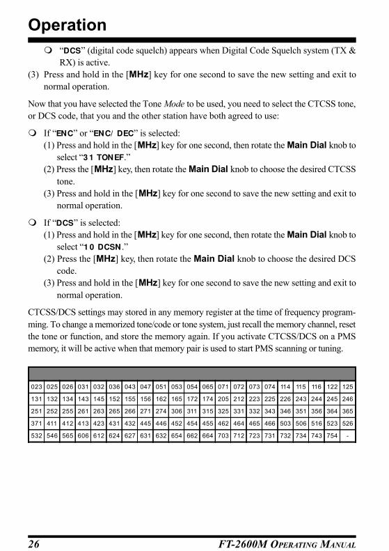
DCS CODES
023 025 026 031 032 036 043 047 051 053 054 065 071 072 073 074 114 115 116 122 125
131 132 134 143 145 152 155 156 162 165 172 174 205 212 223 225 226 243 244 245 246
251 252 255 261 263 265 266 271 274 306 311 315 325 331 332 343 346 351 356 364 365
371 411 412 413 423 431 432 445 446 452 454 455 462 464 465 466 503 506 516 523 526
532 546 565 606 612 624 627 631 632 654 662 664 703 712 723 731 732 734 743 754 -

FT-2600M OPERATING MANUAL 27
CTCSS/DCS SELECTIONS USING PROGRAMMABLE MICROPHONE KEY
One of the microphone’s “Programmable Keys” (P1, P2, or ACC) may be utilized for
comprehensive control over CTCSS and/or DCS operation.
For the discussion below, let us assume that the [P1] key has been assigned the “TONE”
function, per the instructions on page 53.
(1) When you have chosen the desired operating frequency, press the [P1] key momen-
tarily. The display will indicate “OFF” if no CTCSS or DCS code is currently en-
gaged.
(2) Within three seconds, press the [P1] key as many times as required to activate the
desired Tone mode. The available options are:
E (CTCSS Encoder) The current tone will be shown at the right side
of the display.
ED (CTCSS Encoder/Decoder) The current tone will be shown at the right side
of the display, and “CTCSS” will appear at the
top of the display.
DCS (DCS Encoder/Decoder) The current DCS Code # will be shown at the
right side of the display, and “DCS” will ap pear
at the top of the display.
OFF No CTCSS/DCS tone or code is active.
(3) When you have made your selection from the above list, press the microphone’s [UP]
or [DWN] key, as many times as required, to select the desired CTCSS Tone Fre-
quency or DCS Code #.
Note: The above procedure may be performed on a VFO frequency, a Memory Channel,
or the HOME Channel. Any changes you make will be memorized as a “running
change” to the original data, which will be discarded. Therefore, you do not need to
“re-memorize” data if you are modifying CTCSS/DCS information on a memory.
CTCSS TONE SEARCH SCANNING
In operating situations where you don’t know the CTCSS tone being used by another sta-
tion, you can command the radio to listen to the incoming signal and scan in search of the
tone being used.
Before you begin the tone search, please check the (programmable) setting of the microphone’s
[ACC] button (Menu #21); it should be set to “TSRCH” for proper operation.
To scan for the CTCSS tone in use:
(1) Set the radio up for the CTCSS operation.
(2) Press the [ACC] button on the microphone momentarily to start scanning for the in-
coming CTCSS tone.
Operation
FT-2600M OPERATING MANUAL28
(3) When the radio detects the correct tone, it will halt on that tone, and audio will be
allowed to pass.
(4) Press and hold in the [D/MR] key for one second; the CTCSS tone detected will be
stored as the “current” tone, so it may be used for memory storage purposes.
It can be viewed by accessing MENU #31 (TONEF).
(5) Press and hold in the [MHz] key for one second to exit to normaloperaion.
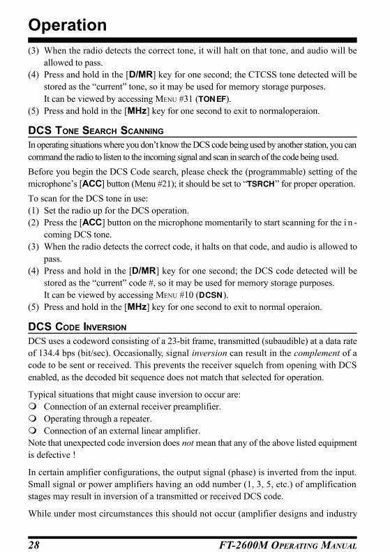
DCS TONE SEARCH SCANNING
In operating situations where you don’t know the DCS code being used by another station, you can
command the radio to listen to the incoming signal and scan in search of the code being used.
Before you begin the DCS Code search, please check the (programmable) setting of the
microphone’s [ACC] button (Menu #21); it should be set to “TSRCH” for proper operation.
To scan for the DCS tone in use:
(1) Set the radio up for the DCS operation.
(2) Press the [ACC] button on the microphone momentarily to start scanning for the i n -
coming DCS tone.
(3) When the radio detects the correct code, it halts on that code, and audio is allowed to
pass.
(4) Press and hold in the [D/MR] key for one second; the DCS code detected will be
stored as the “current” code #, so it may be used for memory storage purposes.
It can be viewed by accessing MENU #10 (DCSN).
(5) Press and hold in the [MHz] key for one second to exit to normal operaion.
DCS CODE INVERSION
DCS uses a codeword consisting of a 23-bit frame, transmitted (subaudible) at a data rate
of 134.4 bps (bit/sec). Occasionally, signal inversion can result in the complement of a
code to be sent or received. This prevents the receiver squelch from opening with DCS
enabled, as the decoded bit sequence does not match that selected for operation.
Typical situations that might cause inversion to occur are:
m Connection of an external receiver preamplifier.
m Operating through a repeater.
m Connection of an external linear amplifier.
Note that unexpected code inversion does not mean that any of the above listed equipment
is defective !
In certain amplifier configurations, the output signal (phase) is inverted from the input.
Small signal or power amplifiers having an odd number (1, 3, 5, etc.) of amplification
stages may result in inversion of a transmitted or received DCS code.
While under most circumstances this should not occur (amplifier designs and industry
Operation

FT-2600M OPERATING MANUAL 29
Operation
standards take this into account), if you find that your receiver squelch does not open when
both you and the other station are using a common DCS code, you or the other station (but
not both) can try the following:
(1) Press and hold in the [MHz] key for one second, then rotate the Main Dial knob to
select “1 1 DCSNR.”
(2) Press the [MHz] key, then rotate the Main Dial knob to select one of the following
modes:
TRX NOR: Encoder: Normal Decoder: Normal
RX REV: Encoder: Normal Decoder: Reverse (Inverted)
TX REV: Encoder: Reverse (Inverted) Decoder: Normal
TRX REV:Encoder: Reverse (Inverted) Decoder: Reverse (Inverted)
(3) Press and hold in the [MHz] key for one second to save the new setting and exit to
normal operation.
Remember to restore the default setting of MENU #11 to “TRX NOR” (Encoder; Normal,
Decoder; Normal) when done.
CTCSS BELL PAGING
CTCSS Bell Paging adds an alert ringer to CTCSS tone squelch operation, for added
convenience. When you receive a call with a matching CTCSS tone, the ringer will sound
to alert you to the presence of the incoming call.
(1) Press and hold in the [MHz] key for one second, then rotate the Main Dial knob to
select “0 5 BELL.”
(2) Press the [MHz] key, then rotate the Main Dial knob to change the display to “ON .”
(3) To de-activate CTCSS Bell operation, select “OFF” in step (2) above.
Calls without a matching CTCSS tone will be ignored during CTCSS Bell operation.
Note that other stations do not need to have the CTCSS Bell function to call you; they can
just use standard CTCSS encoding.
When you reply to a CTCSS Bell call, you may want to turn off the Bell function, or else
the transceiver will ring every time your squelch opens.
You can store the CTCSS Bell Paging function into a memory, along with the CTCSS tone
and encode/decode state.

FT-2600M OPERATING MANUAL30
DTMF AUTODIALER OPERATION
Eight DTMF Autodialer memories are available on the FT-2600M. These DTMF Autodialer
memories can store up to 16 digits of a telephone number for, repeater autopatch or other uses.
To load DTMF Autodialer memories, use following procedure:
(1) Press and hold in the [MHz] key for one second, then rotate the Main Dial knob to
select “1 5 DTM FW .”
(2) Press the [MHz] key, then rotate the Main Dial knob to select the DTMF Autodialer
memory channel number into which you wish store a telephone number (“1 ” to “8 ”).
(3) Press the [D/MR] key momentarily.
(4) Rotate the Main Dial knob to select the first digit of the telephone number you wish
to store.
(5) When you have selected the correct digit, press the [D/MR] key momentarily.
Now rotate the Main Dial knob to select the second of the 16 available numbers in the
current DTMF Autodialer memory register.
(6) Repeat this procedure for each digit in the telephone number.
(7) When entry of all digits is complete, press and hold the the [D/MR] key for one second
to save the new setting. If you wish to store another DTMF string, rotate the Main
Dial knob to select another DTMF Memory register, then repeat steps (3) through (6)
above.
(8) When all required DTMF memories are filled to your satisfaction, press and hold in
the [MHz] key for one second to save the new settings and exit to normal operation.
To transmit the memorized telephone number, use the following procedure:
(1) If you are not working within the MENU system, press and hold in the [MHz] key for
one second, then rotate the Main Dial knob to select “1 5 DTM FW .”
(2) Now press the [MHz] key momentarily to enable selection of the Autodialer Memory.
(3) Rotate the Main Dial knob to select the DTMF Autodialer Memory channel to be
transmitted.
(4) Press and hold in the PTT switch.
(5) While still holding the PTT switch in, press the [MHz] key momentarily to transmit
the tone string.
Once you have pressed the [MHz] button above step, you can release the PTT switch, as
Autodialer transmits the whole DTMF string automatically.
The speed at which the DTMF digits are sent can be changed. Two speed levels are avail-
able: Low (10 digits per second) and High (20 digits per second: default).
To toggle between Low and High speed, use the following procedure:
(1) Press and hold in the [MHz] key for one second, then rotate the Main Dial knob to
select “1 4 DTM FS.”
Operation
FT-2600M OPERATING MANUAL 31
(2) Press the [MHz] key, then rotate the Main Dial knob to select the desired speed: “5 0
ms” (High speed) or “1 0 0 ms” (Low speed).
(3) Press and hold in the [MHz] key for one second to save the new setting and exit to
normal operation.
You can also set a longer delay between the time you press the [MHz] key (with PTT
pressed) and the first DTMF digit is sent.
To set a delay time, use the following procedure:
(1) Press and hold in the [MHz] key for one second, then rotate the Main Dial knob to
select “1 3 DTM FD.”
(2) Press the [MHz] key, then rotate the Main Dial knob to select the desired speed (5 0 /
2 5 0 / 4 5 0 / 7 5 0 / 1 0 0 0 ms).
(3) Press and hold in the [MHz] key for one second to save the new setting and exit to the
normal operation.
Operation

FT-2600M OPERATING MANUAL32
MEMORY STORAGE
To store a frequency into memory:
(1) In the VFO mode, select the desired frequency, repeater shift, CTCSS tone, and TX
power level.
(2) Press and hold in the [D/MR] key for one second. A memory number (or letters and
numbers) will appear (blinking) on the display.
(3) Within five seconds of pressing the [D/MR] key, use the Main Dial knob or the
microphone’s [UP]/[DWN] buttons to select the desired memory for storage (if the
channel is already occupied by data stored previously, the USD notation will appear to
the right of the blinking channel number).
(4) Press the [D/MR] key again, this time momentarily, to store the displayed data into the
selected memory channel slot. The memory label will stop blinking, and the display
will now be blank, except for a blinking digit at the left side of the display. If you wish
to append a name to the just-memorized channel, move quickly to the next step.
Note: If the left digit quits blinking, this indicates that the Alpha-Numeric Storage Timer
has expired. The frequency data will not be lost if this happens, however.
TO APPEND AN ALPHA-NUMERIC LABEL TO A MEMORY
(1) While the right-most digit is still blinking in step (4) above, rotate the Main Dial knob
to select the first character in the name you wish to store, then press the [D/MR] key to
move on to the next character. Letters (both upper and lower case), numbers, and
symbols are available for storage.
(2) Again rotate the Main Dial knob to select the desired number, letter, or symbol, then
press the [D/MR] key to move on to the next character’s slot.
(3) Repeat step (2) as many times as necessary to complete the name tag for the memory,
then press and hold in the [D/MR] key for one second to save the A/N (Alpha-Nu-
meric) name entry and exit to normal operation.
Note: If you wish to append a label to a memory after the Alpha-Numeric Storage Timer
has expired, first recall the memory channel (see below), then press the [MHz] key
for one second to enter the MENU mode. Rotate the Main Dial to select MENU item
#01 (ALPH), then press the [MHz] key momentarily. You will now be ready to begin
with step (1) above.
Memory System Operation

FT-2600M OPERATING MANUAL 33
Memory System Operation
RECALLING MEMORIES
From the VFO mode, momentarily press the [D/MR] key once to activate the “M R” (M emory
Recall) mode.
When more than one memory has been stored, use the Main Dial knob to select a memory
for operation. Alternatively, microphone’s [UP] and [DWN] buttons may be used to step
or scan through the available memories. When using the microphone’s buttons, press and
immediately release the button to move one step up or down; press and hold the [UP] or
[DWN] button for one second to begin memory scanning.
While you are operating in the M R mode, the “M ” notation will appear at the right side of
the display.
MEMORY RECALL FROM MH-36B6J MICROPHONE
While operating in the VFO, HOME Channel (see below), or Memory Recall mode, the
keypad of the MH-36B6J may be used for direct recall of memory channels.
To do this, press the Channel Number you wish to recall, then press the [∗] key. For ex-
ample, to recall Memory Channel 5, press [5]⇒[∗]. To recall Channel number 118, press
[1]⇒[1]⇒[8]⇒[∗].
TO TURN ON THE ALPHA-NUMERIC MEMORY NAME DISPLAY
If you are in the “M R” mode, press the [A/N] key to replace the frequency display with the
Alpha-Numeric Label.
à

FT-2600M OPERATING MANUAL34
HOME CHANNEL MEMORY
A convenient one-touch “HOME” channel memory is available to simplify return to your
most-often-used frequency. This memory does not appear in the regular memory bank, to
simplify operation.
To recall the HOME channel while in the M R mode, just press the [D/MR] key momentarily.
From the VFO mode, press [D/MR] twice. While you are operating on the HOME channel,
an “H ” will appear at the right side of the display.
The factory default frequency for the HOME channel is 146.520 MHz. You can re-program
the HOME channel in a manner identical to that used for the regular memories:
(1) From the VFO mode, tune in the frequency you wish to store, and set all repeater shifts
and other data just the way you do for “normal” memory channel storage.
(2) Press and hold the [D/MR] key for one second, then rotate the Main Dial knob to
select “HOM E.”
(3) Press the [D/MR] key momentarily to store the new HOME channel.
(4) At this point, the right-most digit will be blinking, as a reminder that you can store an
Alpha-Numeric label to the HOME channel. Use the A/N storage procedure described
previously.
MEMORY OFFSET TUNING
Once you have recalled a particular memory channel, you may tune off that channel, as
though you were in the VFO mode.
(1) With the FT-2600M in the “M R” mode, select the desired memory channel.
(2) Press the [MHz] key momentarily.
(3) Now rotate the Main Dial knob, as desired, to tune to a new frequency. This new
frequency may be stored in a new memory register, if you like, using the procedures
described earlier.
(4) If you wish to return to the original memory frequency, press the [D/MR] key momen-
tarily. Any offset tuning will be discarded, and the original memory contents will
appear on the display.
Memory System Operation
à

FT-2600M OPERATING MANUAL 35
MEMORY-ONLY MODE
Once memory channel programming has been completed, you may place the radio in a
“MEMORY-ONLY” mode, whereby VFO and HOME channel operation are impossible. This
may be particularly useful during public-service events where a number of operators may
be using the radio for first time, and ultimate simplicity of channel selection is desired.
To place the radio into the MEMORY-ONLY mode, turn it off. Now press and hold in the [D/
MR] key while turning the radio on. The VFO and HOME channel will now be disabled.
To return to normal operation, repeat the above power-on procedure.
DELETING MEMORIES
With 174 total memories available, there frequently are situations where you may desire to
delete certain memorized frequencies. The procedure for deleting a channel is quite simple:
(1) Press and hold in the [D/MR] key for one second.
(2) Rotate the Main Dial to select the channel to be deleted. Note that Memory Channel
1 may not be deleted, as it is the Priority Channel.
(3) Press the [A/N] button. This will cause the display to shift to Memory Channel 1, and
the previously-selected memory will be deleted.
Important Note: Once deleted, the channel data cannot be recovered.
Memory System Operation
FT-2600M OPERATING MANUAL36
The FT-2600M’s scanning capability provides the operator with many convenient meth-
ods of rapid frequency navigation.
BASIC SCANNER OPERATION
Before activating the scanner, make sure that the Squelch is set to silence the background
noise when no signal is present. If noise is being heard, the scanner will not function (be-
cause the radio will “think” that it is on a “Busy” channel).
Scanning may be started or stopped using the microphone’s [UP] and [DWN] buttons. The
following techniques are used during scanning operation:
(1) Pressing and holding in either the [UP] or [DWN] button for one second in the VFO
mode will cause upward or downward band scanning, respectively, to begin.
(2) Pressing and holding in either the [UP] or [DWN] button for one second in the Memory
Recall mode will cause memory channel scanning toward a higher- or lower-num-
bered memory channel, respectively.
(3) Scanning pauses when a signal opens the squelch, and the decimal point on the display
will blink. You can choose one of two scan-resume modes (described later).
(4) To halt the scan manually, the easiest way is to push the PTT switch on the microphone
momentarily (no transmission will occur while you are scanning).
The scan may also be halted manually by pressing the microphone’s [UP] or [DWN]
button, or the [D/MR] key on the front panel of the radio.
SCAN-RESUME OPTIONS
Two scan-resume modes are available on the FT-2600M:
[1] In the BUSY mode, the scanner will remain halted for as long as there is carrier present
on the channel; after the carrier drops at the end of the other station’s transmission, the
scanner will resume.
[2] In the TIM E mode, the scanner will halt for five seconds only, after which scanning will
resume (whether or not the other station is still transmitting).
To change the scan-resume mode:
(1) Press and hold in the [MHz] key for one second, then rotate the Main Dial knob to
select “2 5 SCAN .”
(2) Press the [MHz] key, then rotate the Main Dial knob to select the desired scan-resume
mode (BUSY or TIM E).
(3) Press and hold in the [MHz] key for one second to save the new setting and exit to
normal operation.
Scanning
FT-2600M OPERATING MANUAL 37
Scanning
MEMORY SKIP SCANNING (MR MODE)When you have some continuously-active channels (like Weather broadcasts) in memo-
ries, you may wish to skip them for scanning, but still have them available for manual
selection.
To select a memory to be skipped during scanning:
(1) Recall the memory channel to be skipped. Note that Memory Channel 1 may not be
skipped, as it is the Priority Channel.
(2) Press and hold in the [MHz] key for one second, then rotate the Main Dial knob to
select “2 7 SKIP.”
(3) Press the [MHz] key, then rotate the Main Dial knob to select “SKIP.”
(4) Press and hold in the [MHz] key for one second to save the new setting and exit to
normal operation.
To re-enable a “skipped” memory channel, select “STOP” in step (3) above.
TEMPORARY MEMORY SKIP
If the scanner repeatedly stops on a channel due to temporary noise or interference, you
can temporarily mark it to be skipped. The channel will be skipped until you manually stop
the scan (by pressing the PTT switch, for example).
To skip a channel temporarily, press the [MHz] key momentarily while the scanner has
stopped on the channel to be skipped. The scanner will instantaneously resume, and that
channel will not be scanned during this scanning session. Note that Memory Channel 1
may not be skipped, as it is the Priority Channel.

FT-2600M OPERATING MANUAL38
PROGRAMMABLE BAND-SCAN LIMITS
Besides band and memory scanning, this radio can be set to tune or scan only the frequen-
cies between user-defined lower and upper limits. For example, you may wish to limit
tuning/scanning to 144.5 ~ 148 MHz, to avoid encroachment on the SSB/CW sub-band
between 144.0 and 144.5 MHz.
These scanning limits are stored in special “Sub-Band Limit Memories,” labeled PM S-
1 L, PM S-1 U, PM S-2 L, and PM S-2 U, with “L” and “U” designations representing the Lower
and Upper limits, respectively.
To utilize this feature, use the following steps:
(1) Store the lower edge of the desired scanning/tuning range in memory “PM S-1 L,” and
the upper edge in memory “PM S-1 U” (or, alternatively, in memories “PM S-2 L” and
“PM S-2 U”).
(2) With any of these memories recalled, press the [MHz] key momentarily to activate the
Programmable Band-Scan Limits. The “P” notation will appear at the right side of the
display, reminding you that you are using the Programmable Band Limits.
The frequencies stored in memories “L” and “U” will now serve as tuning and scanning
limits, thus creating a tuning sub-band.
To cancel the sub-band limits and return to normal memory operation, press the [D/MR]
key momentarily.
Note: If the frequency in memory channel “PM S-xL” is equal to or greater than the fre-
quency stored in memory channel “PM S-xU,” you can not activate the PMS operation.
Scanning

FT-2600M OPERATING MANUAL 39
SMART SEARCH OPERATION
The Smart Search feature may be used to load – automatically with no operator interven-
tion – a special bank of up to 50 memory channels (per band) based on activity. Smart
Search will sweep either the entire band or the portion of the band within the Program-
mable Band-Scan Limits, and will load the special memory bank with the frequency and
repeater shift data pertaining to those channels on which activity is found (if Automatic
Repeater Shift is activated). The channels are loaded in the order in which they are encoun-
tered, not according to signal strength or by ascending frequency.
The Smart Search feature is especially useful when visiting a city for the first time, where
you may be unfamiliar with the repeater frequencies; Smart Search discovers where the
local activity is to be found, and automatically loads those frequencies for you.
Smart Search operation is simple to activate:
(1) Press the [P2] key.*
(2) The Smart Search process will now cause the radio to scan upward on current band,
loading channels on which it encounters a signal strong enough to open the squelch.
(3) When 50 channels are loaded or scanner is reached band edge, the scanner will stop
and the transceiver will revert to the starting frequency.
(4) To recall the Smart Search Memories just stored, rotate the Main Dial knob or press
the microphone’s [UP] or [DWN] key.
(5) If you find particular channels which you wish to store into the “regular” memory
system, follow the memory storage procedures described on page 32.
(6) Press the [D/MR] key momentarily to exit the Smart Search mode.
Note that these memories are so-called “soft” memories; they will be lost if you exit the
Smart Search mode or initiate a new Smart Search sweep.
* The (user-programmable) [P2] key is set at the factory for Smart Search operation.
It may be assigned to one of the other programmable keys, if you like. See page 53.
Scanning

FT-2600M OPERATING MANUAL40
PRIORITY CHANNEL MONITORING
The Priority function allows automatic checking for activity on Memory Channel 001 ev-
ery five seconds while operating on the VFO or a different memory. When the receiver
detects a signal on the “Priority” memory, operation automatically shifts to that channel
while the signal is present (plus a few seconds). If you transmit while “paused” on the
Priority channel, priority monitoring will cease, and the transceiver will “hold” indefi-
nitely on the Priority channel. Only Channel 001 is available as the “Priority” channel.
To set up for priority monitoring:
(1) Preset the SQL control to silence the background noise on a clear channel, then store
the frequency to be the “Priority” channel into Memory Channel 001.
(2) Press the [D/MR] key to operate in the VFO mode. If you are in the memory mode,
select the memory on which you wish to operate (other than the Priority channel).
(3) Press and hold in the [A/N] key for one second to initiate priority monitoring. The
“PRI” (“Priority Channel”) notation will appear at the top of the display.
During priority monitoring, the displayed frequency will shift to the priority memory briefly
about every five seconds, while the receiver checks for the presence of a signal.
While no signal appears on the Priority memory (causing the squelch to open), you can
tune, transmit and receive on the VFO, or select and operate on other memories; however,
you cannot scan (except manually, one step at a time, using the microphone’s [UP] and
[DWN] buttons), as the scanning logic circuits are already dedicated to the priority scan-
ning activities.
If a station you wish to talk with appears on the Priority memory, press the PTT switch
momentarily while receiving their signal (no transmission will occur) to halt priority scan-
ning. At this point, the FT-2600M will be shifted to the M R mode on Channel 001, and the
previous operating status (VFO, M R, or HOM E) will be ignored.
Otherwise, if you elect not to call the station appearing on the Priority channel, priority
monitoring will pause and the decimal on the display will blink. Priority monitoring will
resume based on the setting of the regular scanning-resume mode – either after a 5-second
pause, or after the carrier drops out.
To cancel priority monitoring, press the [D/MR] key momentarily.
The priority function is not disabled by switching the transceiver off. If you were engaged
in priority monitoring at the moment you turned the radio off, it will assume that you will
want to continue priority monitoring during your next operating session, and will come up
still in the priority mode when the transceiver is switched back on.
Scanning

FT-2600M OPERATING MANUAL 41
Scanning
PRIORITY REVERT MODE
During Priority channel operation (Dual Watch), a special feature is available which will
allow you to move to the Priority Channel instantly, without waiting for activity to appear
on the Priority Channel.
When this feature is enabled, and Priority monitoring is engaged, just press the microphone’s
PTT button. Operation will instantly revert to the Priority Channel.
To enable Priority Revert operation:
(1) Press and hold in the [MHz] key for one second, then rotate the Main Dial knob to
select “2 4 RVRT.”
(2) Press the [MHz] key, then rotate the Main Dial knob to select “ON .”
(3) Press and hold in the [MHz] key for one second to save the new setting and exit to
normal operation.
To disable Priority Revert operation, select “OFF” in step (2) above.

FT-2600M OPERATING MANUAL42
This system uses DCS signaling to inform you when you and another ARTS-equipped
station are within communications range. Both stations must first select DCS operation
using the same DCS code.
Whenever you press the PTT, or every 30 seconds after ARTS is activated, your radio
transmits a (subaudible) DCS signal. If the other radio is in range, the beeper (if enabled)
will sound, and “ARTSlogo” will flash on the display.
Whether you talk or not, the radios will continue to poll each other every 30 seconds while
ARTS is activated. You can also have your radio transmit your callsign via CW every nine
minutes, to comply with identification requirements.
If you move out range for more than one minute (two polls), your radio senses that no
signal has been received. The beeper will sound, and the “ARTSlogo” will stop flashing. If
you move back into range, your radio will again beep, and the”ARTSlogo” will again
flash.
During ARTS operation, it is not possible to change the operating frequency or other set-
tings; you must first terminate ARTS to resume normal operation. This is a safety feature to
prevent accidental loss of contact due to channel change, etc.
ARTS BASIC OPERATION
Here is how to activate ARTS:
(1) Press and hold in the [MHz] key for one second, then rotate the Main Dial knob to
select “0 3 ARTS.”
(2) Press the [MHz] key, then rotate the Main Dial knob to select the ARTS operating
mode: “RX (receive-only),” “TX (transmit-only),” “TRX (transceive),” or “OFF.” The
operating descriptions assume both radios are set to “TRX.”
(3) Press and hold in the [MHz] key for one second to save the entry and exit. The “ARTS”
icon will appear in the display. The display will now show “ARTS ” icon. After two
pollings (one minute), if a response is not detected, “ARTS” icon will appear continu-
ously; otherwise, “ARTS” icon will be flashed as long as both stations remain in range.
(4) To cancel ARTS operation, select “OFF” in step (2) above.
ARTS™: Auto Range Transpond System

FT-2600M OPERATING MANUAL 43
ARTS™: Auto Range Transpond System
ARTS MODES
In the previous ARTS description, both transceivers were set to the “TRX” (transceive)
mode. There are two other ARTS modes available from MENU #03, as outlined below:
RX – Use this mode if you only want your radio to listen, and not poll the other station
(in which case their radio should be set to the “TX” mode). Here, your radio will
beep and flash “ARTS” icon to indicate the state of connection.
TX – Likewise, this puts your radio into a transmit-only “beacon” mode where you
won’t hear the polling beeps (but you can still hear when the other station talks).
When activated, you have no display of whether or not the other station is in
range (“ARTS” icon do not appear). You should have your CW IDer enabled
when this mode is activated.
CW ID (MORSE IDENTIFIER) SET UP
The ARTS feature includes a CW identifier, as mentioned previously. The FT-2600M can
be instructed to send “DE (your callsign) K” in Morse code every nine minutes during
ARTS operation. The callsign field may contain up to 7 characters.
Here’s how to program the CW IDer:
(1) Press and hold in the [MHz] key for one second, then rotate the Main Dial knob to
select “0 8 CW IDN .”
(2) Press the [MHz] key. You will notice the first entry’s place blinking. This indicates the
CW ID Entry Mode. In this mode, rotate the Main Dial knob to select the numbers
and letters in the callsign, and press the [D/MR] key to move the character’s entry
place to the right.
(3) Rotate the Main Dial knob to select the first number or letter in the callsign, then press
the [D/MR] key to move the next character’s place.
(4) Repeat step (3) as many times as necessary to complete the callsign entry.
(5) Press and hold in the [MHz] key for one second to save the CW IDer entry and exit to
normal operation.
To activate the CW IDer:
(1) Press and hold in the [MHz] key for one second, then rotate the Main Dial knob to
select “0 7 CW ID.”
(2) Press the [MHz] key, then rotate the Main Dial knob to change the display to “ON .”
(3) Press and hold in the [MHz] key for one second to save the new setting and exit to
normal operation.
To disable the CW IDer, select “OFF” in step (2) above.

FT-2600M OPERATING MANUAL44
Packet Operation
Once you have connected your TNC and computer according to the instructions on page
13, there normally is no other configuration of the FT-2600M required for successful op-
eration. The transceiver will automatically be configured for the proper baud rate (1200
bps or 9600 bps) depending on the signal path of the data passing via the rear panel’s DATA
connector.
Normally, the microphone will be cut off during packet transmission, so as to avoid inter-
ference to the data stream by voice input. However, this protection feature can be disabled,
if you have some reason to want the microphone to be active during packet transmission.
To re-activate the microphone during packet transmission:
(1) Press and hold in the [MHz] key for one second, then rotate the Main Dial knob to
select “1 8 PCKT.”
(2) Press the [MHz] key, then rotate the Main Dial knob to select “M IC ON .”
(3) Press and hold in the [MHz] key for one second to save the new setting and exit to
normal operation.
To disable the microphone during packet transmission (the typical configuration), select
“M IC OFF” in step (2) above.
Packet operating procedures are governed by the software used by your computer and
TNC. Consult the documentation accompanying the software for details on packet opera-
tion.
FT-2600M OPERATING MANUAL 45
Miscellaneous Settings
TIME-OUT TIMER
The “Time-Out Timer” (TOT) feature is designed to force the transceiver into the “re-
ceive” mode after a preset time period of continuous transmission (the default is 6 min-
utes). This feature prevents your transceiver from transmitting a “dead carrier” for a long
period of time in the event that the microphone PTT switch is accidentally locked in the
“TX” condition.
The Time-Out Timer’s “switch-to-receive” time may be adjusted, in one minute incre-
ments, for any period between 1 and 60 minutes.
To change the default (6 minute) time setting as follows:
(1) Press and hold in the [MHz] key for one second, then rotate the Main Dial knob to
select “3 2 TOT.”
(2) Press the [MHz] key, then rotate the Main Dial knob to select the desired time interval
(between 1 and 6 0 minutes, or OFF).
(3) Press and hold in the [MHz] key for one second to save the new setting and exit to
normal operation.
AUTOMATIC POWER-OFF
The “Automatic Power-Off” (APO) feature will turn the radio completely off after a user-
defined period of PTT or key/button inactivity. If you do not press any front panel keys or
buttons, rotate the Main Dial knob, use the microphone’s keys and buttons, or transmit,
and so long as the transceiver is not scanning or engaged in priority monitoring, the radio
will shut itself off after the specified time period. This feature is useful in minimizing
battery drain in a mobile installation if you forget to turn the transceiver off when you leave
your vehicle.
To activate the APO feature as follows:
(1) Press and hold in the [MHz] key for one second, then rotate the Main Dial knob to
select “0 2 APO.”
(2) Press the [MHz] key, then rotate the Main Dial knob to select the desired “switch-off”
time (between 1 and 1 2 hours, or OFF).
(3) Press and hold in the [MHz] key for one second to save the new setting and exit to
normal operation.

FT-2600M OPERATING MANUAL46
Miscellaneous Settings
FM BANDWIDTH & MIC GAIN CONTROL
You can reduce the microphone input level and receiver bandwidth when operating on
tightly-clustered frequencies (channel spacing of 12.5- or 15-kHz). This will reduce the
transmitter and receiver deviation , thus minimizing interference to other users.
To reduce the microphone input level:
(1) Press and hold in the [MHz] key for one second, then rotate the Main Dial knob to
select “3 3 W / N .”
(2) Press the [MHz] key, then rotate the Main Dial knob to change the display to “NARROW .”
(3) Press and hold in the [MHz] key for one second to save the new setting and exit to
normal operation.
To restore the normal (higher) microphone input level and normal (15 kHz) receiver band-
width, select “W IDE” in step (2) above.

FT-2600M OPERATING MANUAL 47
PROGRAMMABLE MICROPHONE KEYS (ACC/P1/P2)Default FT-2600M key functions have been assigned (at the factory) to the microphone’s
[P1], [P2], and [ACC] buttons. These may be changed by the user, if you wish to define
another function for a particular key or keys.
To change the assignment of a key’s function:
(1) Press and hold in the [MHz] key for one second, then rotate the Main Dial knob to the
Menu Item # corresponding to the key to be assigned a function (1 9 PG P1 , 2 0 PG
P2 , or 2 1 PG AC).
(2) Press the [MHz] key momentarily, then rotate the Main Dial knob to select the func-
tion you wish to assign to the key or button you selected in the previous step. The
available choices are:
SQL OFF Opens the Squelch to allow un-muted reception.
SSRCH Initiates Smart Search scanning.
TONE Selects CTCSS or DCS mode and frequency/code.
TSRCH Initiates scanning for (unknown) CTCSS/DCS tone or code.
T. BURST Activates 1750 Hz Tone Burst.
RPTR Selects Repeater Shift direction.
(3) Press the [MHz] key momentarily to lock in the new setting.
(4) Rotate the Main Dial knob to select another programmable key or button to modify, if
desired, from the remaining MENU items. Follow the procedure outlined above.
(5) Press and hold in the [MHz] key for one second to save the new setting and exit to
normal operation.
Note: The function of the [P] key is fixed on the [D/ M R/ HOM E] selection.
Miscellaneous Settings

FT-2600M OPERATING MANUAL48
RESET ALL MENU SETTINGS
To reset all MENU settings to their factory defaults, press the [REV] key and [D/MR] but-
tons while turning the transceiver on.
CPU MASTER RESET FOR ALL MEMORIES AND MENU SETTINGS
To perform a CPU master reset for all memories and MENU settings, press the [A/N],
and [D/MR] keys while turning the transceiver on.
Resetting the CPU

FT-2600M OPERATING MANUAL 49
Transceiver Cloning
You can transfer all data stored in one transceiver to another set by utilizing the handy
“CLONING” feature. This requires a user-constructed cloning cable which connects the MIC
jacks on the two transceivers as shown below.
To clone from one transceiver to another, use the following procedure:
(1) Insert the Clone Cable into the MIC jack of each transceiver.
(2) Turn both transceivers off, then press and hold in the [A/N] key on each radio while
turning the power on again. The “CLN” notation will appear on the display.
(3) On the “destination” radio, press the [D/MR] button.
(4) Now, on the “source” radio, press the [MHz] key.
(5) If there is a problem during the cloning process, “CLN ERR” will be displayed. Check
your cable connections and try again.
(6) If cloning is successful, turn the “destination” radio off. Now turn the “source” radio
off.
Remove the clone cable. Channel and operating data for both radios are now identical.
They both may be turned on now for normal operation.

FT-2600M OPERATING MANUAL50
The FT-2600M’s MENU system allows a number of transceiver operating parameters to be
custom-configured for your operating requirements.
The MENU is easy to activate and set, using the following procedure:
Press and hold in the [MHz] key for one second.
Rotate the Main Dial knob to select the MENU item to be adjusted.
Press the [MHz] key, then rotate the Main Dial knob to adjust the status or value of
the MENU item.
After completing your adjustment, press and hold in the [MHz] key for one second
to save the new setting and exit to normal operation.
MENU items are conveniently arranged in alphabetical order.
MENU SELECTION SUMMARY
Menu System
ltem # Menu ltem Function Available Values Default
01 ALPH Programming an Alpha/Numeric label for a memory − −
02 APO Enable/Disable the Automatic Power Off feature 1 ~ 12 Hours, or OFF OFF
03 ARTS Select the ARTS mode TRX/TX/RX/OFF OFF
04 BEEP Enable/Disable the key/button beeper ON/OFF ON
05 BELL Enable/Disable the CTCSS Bell Paging feature ON/OFF OFF
06CHNUM Enable/Disable the momentary display of the
Memory Channel Number
ON/OFF OFF
07CWID Enable/Disable the CW Identifier during ARTS
operation
ON/OFF OFF
08CWIDN Program the callsign used by the ARTS CW
Identifier
− YAESU
09 DC IN Indicate the DC Supply Voltage − −
10 DCSN Setting of the DCS Code # 104 standard DCS codes 023
11DCSNR Select "Normal" or "Inverted" DCS coding TRX NOR/RX REV/TX
REV/TRX REV
TRX NOR
12 DIMR Setting of the front panel display's illumination level D1/D2/D3/D4/OFF D1
13 DTMFD Setting of the DTMF Autodialer Delay Time 50/250/450/750/1000 ms. 450 ms.
14 DTMFS Setting of the DTMF Autodialer Sending Speed 50/100 ms. 50 ms.
15 DTMFW Loading of the DTMF Autodialer Memories − −
16 LCKTX Enable/Disable the PTT Lock ON/OFF OFF
17 LOCK Enable/Disable the key/button Lock ON/OFF OFF
18PCKT Enable/Disable the Microphone during Packet
transmission
MIC OFF/MIC ON MIC OFF
19PG P1 Programming the function assigned to microphone
key P1
SQL OFF/SSRCH/TONE/
TSRCH / T-BURST/RPTR
SQL OFF
20PG P2 Programming the function assigned to microphone
key P2
SQL OFF/SSRCH/TONE/
TSRCH/T-BURST/RPTR
SSRCH

FT-2600M OPERATING MANUAL 51
Menu System
MENU SELECTION DETAILS
0 1 ALPH
Function: Programming an Alpha/Numeric label for a memory. See page 32.
0 2 APO
Function: Enable/Disable the Automatic Power Off feature.
Available Values: 1 ~ 12 Hours, or OFF
Default Setting: OFF
0 3 ARTS
Function: Select the ARTS mode.
Available Values: TRX/TX/RX/OFF
Default Setting: OFF
0 4 BEEP
Function: Enable/Disable the key/button beeper.
Available Values: ON/OFF
Default Setting: ON
0 5 BELL
Function: Enable/Disable the CTCSS Bell Paging feature.
Available Values: ON/OFF
Default Setting: OFF
ltem # Menu ltem Function Available Values Default
21PG AC Programming the function assigned to microphone
key ACC
SQL OFF/SSRCH/TONE/
TSRCH/T_BURST/RPTR
TSRCH
22 RFSQL Adjust the RF Squelch threshold level OFF/S-3/S-5/S-7/S-9/S-FULL OFF
23 RPTR Setting of the Repeater Shift Direction ARS/Shift -/Shift +/OFF ARS
24 RVRT Enable/Disable the "Priority Channel Revert" feature OFF/ON OFF
25 SCAN Select the Scan Resume mode BUSY/TIME BUSY
26SHIFT Set the magnitude of the Repeater Shift 0.00 ~ 99.95 MHz
(only 4 MHz will work)
600 kHz
27SKIP Enable/Disable Skipping of a channel during
scanning
SKIP/STOP STOP
28 SQL Set the Squelch threshold OFF/1 ~ 15 8
29STEP Setting of the synthesizer steps used in VFO or
Memory Tune operation
5/10/12.5/15/20/25/50 kHz per
step
5 kHz
30 TONE Select the CTCSS or DCS mode OFF, ENC, ENC/DEC, DCS OFF
31 TONEF Setting of the CTCSS Tone Frequency 47 standard CTCSS Tones 100.0 Hz
32 TOT Set the time-out limit for the Time-Out Timer 1 ~ 60 minutes, or OFF 6 minutes
33W/N Reduction of the Microphone Gain/Deviation and
receiver bandwidth
WIDE/NARROW WIDE
±

FT-2600M OPERATING MANUAL52
0 6 CHNUM
Function: Enable/Disable the momentary display of the Memory Channel Num-
ber as the Main Dial knob is rotated.
Available Values: ON/OFF
Default Setting: OFF
0 7 CW ID
Function: Enable/Disable the CW Identifier during ARTS operation.
The callsign also appears briefly when the radio is turned on.
Available Values: ON/OFF
Default Setting: OFF
0 8 CW IDN
Function: Program the callsign used by the ARTS CW Identifier.
Default Setting: YAESU
0 9 DC IN
Function: Indicate the Supply Voltage
1 0 DCSN
Function: Setting of the DCS Code #.
Available Values: 104 standard DCS codes.
Default Setting: 023
1 1 DCSNR
Function: Select “Normal” or “Inverted” DCS coding.
Available Values: TRX NOR (Encoder: Normal Decoder: Normal)
RX REV (Encoder: Normal Decoder: Inverted)
TX REV (Encoder: Inverted Decoder: Normal)
TRX REV (Encoder: Inverted Decoder: Inverted)
Default Setting: TRX NOR (Encoder: Normal Decoder: Normal)
1 2 DIM R
Function: Setting of the front panel display’s illumination level.
Available Values: D1/D2/D3/D4/OFF
Default Setting: D1 (brightest setting)
1 3 DTM FD
Function: Setting of the DTMF Autodialer Delay Time
Available Values: 50/250/450/750/1000 ms.
Default Setting: 450 ms.
Menu System
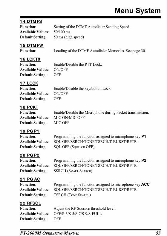
FT-2600M OPERATING MANUAL 53
1 4 DTM FS
Function: Setting of the DTMF Autodialer Sending Speed
Available Values: 50/100 ms.
Default Setting: 50 ms (high speed)
1 5 DTM FW
Function: Loading of the DTMF Autodialer Memories. See page 30.
1 6 LCKTX
Function: Enable/Disable the PTT Lock.
Available Values: ON/OFF
Default Setting: OFF
1 7 LOCK
Function: Enable/Disable the key/button Lock
Available Values: ON/OFF
Default Setting: OFF
1 8 PCKT
Function: Enable/Disable the Microphone during Packet transmission.
Available Values: MIC ON/MIC OFF
Default Setting: MIC OFF
1 9 PG P1
Function: Programming the function assigned to microphone key P1
Available Values: SQL OFF/SSRCH/TONE/TSRCH/T-BURST/RPTR
Default Setting: SQL OFF (SQUELCH OFF)
2 0 PG P2
Function: Programming the function assigned to microphone key P2
Available Values: SQL OFF/SSRCH/TONE/TSRCH/T-BURST/RPTR
Default Setting: SSRCH (SMART SEARCH)
2 1 PG AC
Function: Programming the function assigned to microphone key ACC
Available Values: SQL OFF/SSRCH/TONE/TSRCH/T-BURST/RPTR
Default Setting: TSRCH (TONE SEARCH)
2 2 RFSQL
Function: Adjust the RF SQUELCH threshold level.
Available Values: OFF/S-3/S-5/S-7/S-9/S-FULL
Default Setting: OFF
Menu System
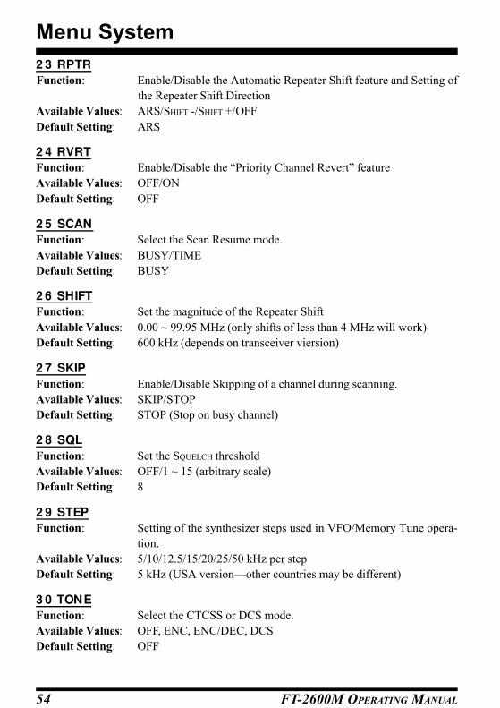
FT-2600M OPERATING MANUAL54
2 3 RPTR
Function: Enable/Disable the Automatic Repeater Shift feature and Setting of
the Repeater Shift Direction
Available Values: ARS/SHIFT -/SHIFT +/OFF
Default Setting: ARS
2 4 RVRT
Function: Enable/Disable the “Priority Channel Revert” feature
Available Values: OFF/ON
Default Setting: OFF
2 5 SCAN
Function: Select the Scan Resume mode.
Available Values: BUSY/TIME
Default Setting: BUSY
2 6 SHIFT
Function: Set the magnitude of the Repeater Shift
Available Values: 0.00 ~ 99.95 MHz (only shifts of less than 4 MHz will work)
Default Setting: 600 kHz (depends on transceiver viersion)
2 7 SKIP
Function: Enable/Disable Skipping of a channel during scanning.
Available Values: SKIP/STOP
Default Setting: STOP (Stop on busy channel)
2 8 SQL
Function: Set the SQUELCH threshold
Available Values: OFF/1 ~ 15 (arbitrary scale)
Default Setting: 8
2 9 STEP
Function: Setting of the synthesizer steps used in VFO/Memory Tune opera-
tion.
Available Values: 5/10/12.5/15/20/25/50 kHz per step
Default Setting: 5 kHz (USA version—other countries may be different)
3 0 TONE
Function: Select the CTCSS or DCS mode.
Available Values: OFF, ENC, ENC/DEC, DCS
Default Setting: OFF
Menu System

FT-2600M OPERATING MANUAL 55
Menu System
3 1 TONEF
Function: Setting of the CTCSS Tone Frequency (use MENU #10 FOR DCS)
Available Values: 47 standard CTCSS Tones
Default Setting: 100.0 Hz
3 2 TOT
Function: Set the time-out limit for the Time-Out Timer
Available Values: 1 ~ 60 minutes, or OFF
Default Setting: 6 minutes
3 3 W / N
Function: Reduction of the Microphone Gain/Deviation and receiver bandwidth
Available Values: WIDE/NARROW
Default Setting: WIDE (±5 kHz Deviation, 15 kHz bandwidth)

FT-2600M OPERATING MANUAL56
Menu System
NOTE


This device complies with Part 15 of the FCC rules.
Operation is subject to the condition that this device
does not cause harmful interference.

E 1 3 1 5 1 0 0 0
Copyright 2001
VERTEX STANDARD CO., LTD.
All rights reserved.
Printed in Japan
No portion of this manual
may be reproduced
without the permission of
VERTEX STANDARD CO., LTD.