1418-1, Capacitors and Capacitive Circuits · PDF fileimportant to the experiment. ......
20
1418-1, Capacitors and Capacitive Circuits Experiment 5: How Frequency Affects Capacitive Reactance
-
Upload
hoanghuong -
Category
Documents
-
view
218 -
download
0
Transcript of 1418-1, Capacitors and Capacitive Circuits · PDF fileimportant to the experiment. ......
1418-1, Capacitors
and Capacitive
Circuits
Experiment 5: How Frequency Affects Capacitive Reactance
Objective of Experiment 5
• To verify that capacitive reactance
(XC) varies inversely with applied
frequency.
• This means that (XC) will increase as
frequency decreases
• This also means that (XC) will decrease
as frequency increases

• f = frequency of applied signal in Hertz
• C = Capacitance of the capacitor in Farads
• 2π = is a constant whose value is
approximately 6.28

Figure 18 of 1418-1

• Be aware that the frequency
calibration of the frequency generator
in your trainer is limited in accuracy.
• We are no-longer using the 30VAC
60Hz as our Input
Suggested Procedure 1. Construct the circuit
I. Connect 0.039µF capacitor between terminals A and B.
2. Apply the 200Hz Signal to terminal A
I. Your goal is to have VC equal to VR
a. Place Common (Black) lead at Terminal B.
b. Place a jumper post at point B
in your circuit.

c. Clip the Black meter probe lead to
post “B” with an alligator clip or lead.
d. Move the Red lead/meter probe
between Terminals A and C.
i. Make small adjustments on the pot.
a. 1st Measure Voltage across capacitor
b. Then the Pot, adjust pot to match
ii. Keep making fine adjustments by
measuring the AC voltage at points A
and C until A = C.
e. Turn off the trainer after the
measurements have been made and
the voltages are the same.
f. Disconnect the leads from the Pot,
measure and record the measurement
in Fig/table 17 of the lab.
3. While we are listing DC voltage (not
AC effective) measurements in our
results, these results are not really
important to the experiment.
What we are really interested in are the
resistance measurements and the trends
they show.
I. This is because the voltage
measurements can vary widely
depending on actual circuit conditions.
II. It is not necessary to look up the
effective values of the voltages.

• Remember the following:
1. The blocking capacitor is only used with
the Analog meter!
2. The voltage doubler is only needed with
the analog meter.
1. The voltage doubler can be used with a
digital meter, but is not required.
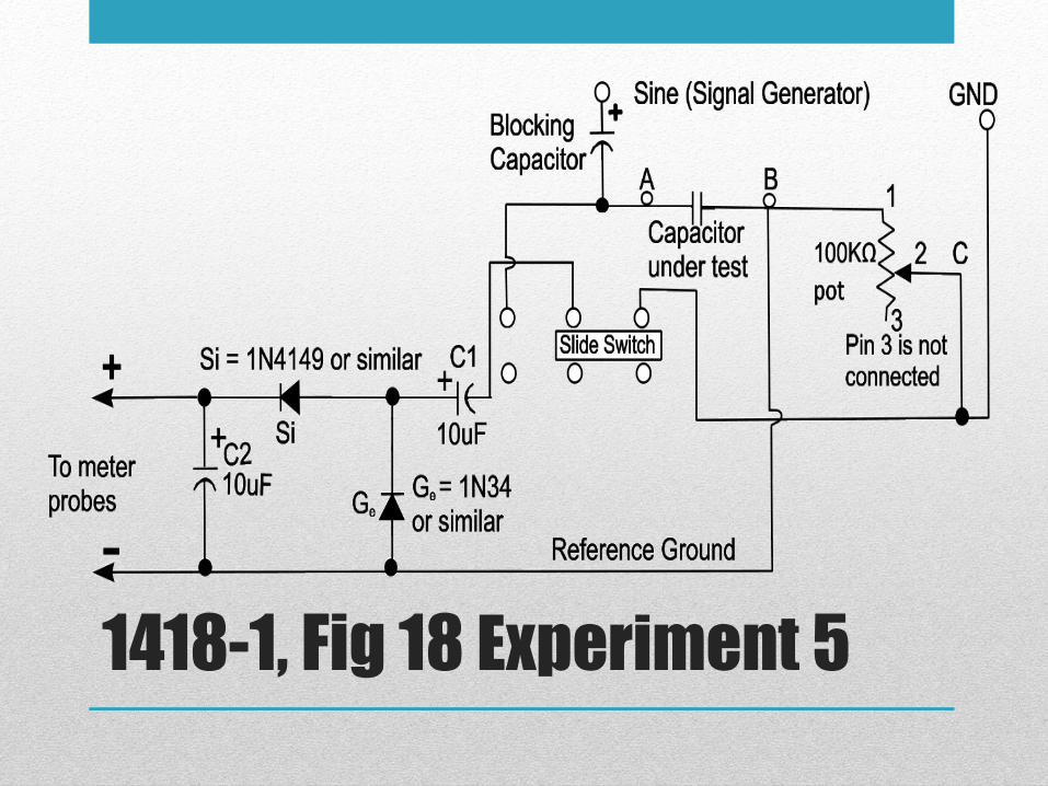
1418-1, Fig 18 Experiment 5

1418-1, Exp. 5, Fig 19 built
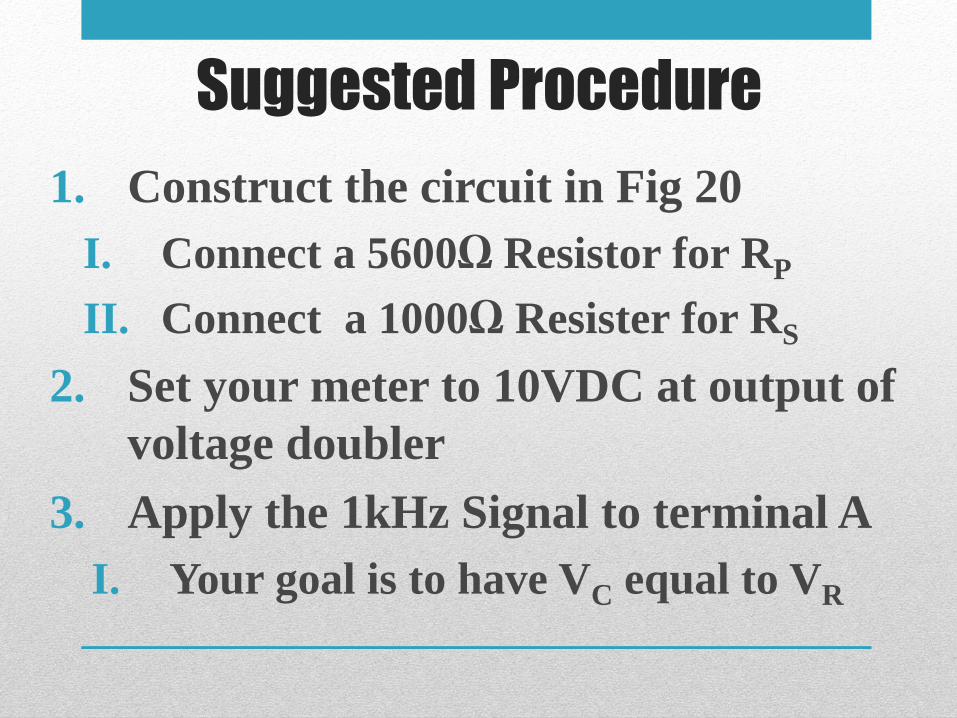
Suggested Procedure
1. Construct the circuit in Fig 20
I. Connect a 5600Ω Resistor for RP
II. Connect a 1000Ω Resister for RS
2. Set your meter to 10VDC at output of
voltage doubler
3. Apply the 1kHz Signal to terminal A
I. Your goal is to have VC equal to VR

4. Use the slide switch and the 100k pot so you have equal voltage readings at both positions of the slide switch.
I. It is normal for the needle of the meter to jump when you change the switch settings, but when the needle settles on the same value for both settings, the circuit is balanced.
5. Record the voltage measurements and Frequency in Figure 17.

6. Continue with the experiment
changing the components and
recording the values as indicated.
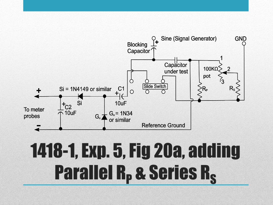
1418-1, Exp. 5, Fig 20a, adding
Parallel RP & Series RS
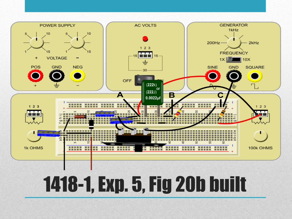
1418-1, Exp. 5, Fig 20b built
CIE Results
• When analyzing the CIE results, we find
that a change in frequency of 10:1
produced a change in capacitance
reactance of approximately 1:6.5.
• Under formal conditions, this data would
not be acceptable; however, with the poor
frequency calibration, we were still able to
verify capacitive reactance does decrease
with an increase in frequency.

Questions?
The End
Developed and Produced by the Instructors in the CIE Instruction
Department.
© Copyright 04/2012
All Rights Reserved / April 2012