
140331 Yonge Subway Storage Facility Noise and Vibration ...
30
Air Quality | Sound, Vibration & EMI/RFI | Sustainable Water | Wind & Climate Novus Environmental Inc. | 150 Research Lane, Suite 105, Guelph, Ontario, Canada N1G 4T2 e-mail [email protected] tel 226.706.8080 fax 226.706.8081 Yonge Street Subway Extension Project Train Storage and Maintenance Facility Environmental Noise and Vibration Assessment Novus Reference No. 12-0111 Version No. 2 (FINAL) March 2014 NOVUS PROJECT TEAM: Scientist: Kevin Carr, P.Phys. Specialist: Brad Pridham, P.Eng., Ph.D. Specialist: R. L. Scott Penton, P.Eng. Project Manager: Scott Shayko, Hon.B.Comm, B.Sc.
Transcript of 140331 Yonge Subway Storage Facility Noise and Vibration ...
Air Quality | Sound, Vibration & EMI/RFI | Sustainable Water | Wind & Climate Novus Environmental Inc. | 150 Research Lane, Suite 105, Guelph, Ontario, Canada N1G 4T2
e-mail [email protected] tel 226.706.8080 fax 226.706.8081
Yonge Street Subway Extension Project Train Storage and Maintenance Facility Environmental Noise and Vibration Assessment Novus Reference No. 12-0111 Version No. 2 (FINAL) March 2014 NOVUS PROJECT TEAM: Scientist: Kevin Carr, P.Phys. Specialist: Brad Pridham, P.Eng., Ph.D. Specialist: R. L. Scott Penton, P.Eng. Project Manager: Scott Shayko, Hon.B.Comm, B.Sc.

This page intentionally left blank for 2-sided printing purposes
Environmental Noise and Vibration Assessment March 2014
Novus Environmental | i
Table of Contents
1.0 Introduction .................................................................................................................................. 1
1.1 Project Background .......................................................................................................... 1 1.1.1 Planning Requirements and Design Considerations ............................................ 1 1.1.2 Facility Operations ............................................................................................... 1
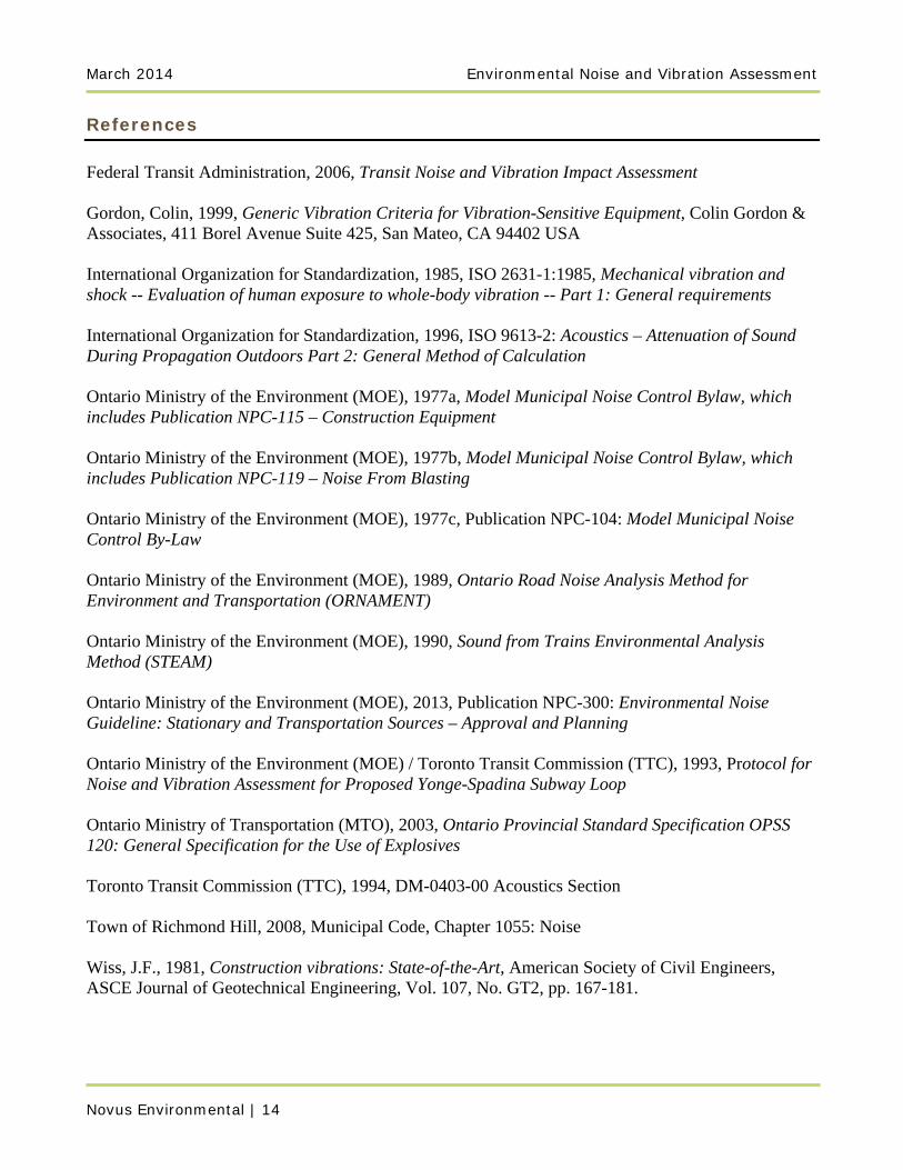
1.2 Key Features within the Study Area ................................................................................. 2
2.0 Noise and Vibration Assessment Criteria .................................................................................... 2
2.1 Noise from Subway Surface Operations .......................................................................... 2 2.2 Noise from “Stationary” Operations ................................................................................ 2 2.3 Vibration from Subway Operations ................................................................................. 4
2.3.1 Residential ............................................................................................................ 4 2.3.2 Vibration-Sensitive Industrial / Commercial Uses ............................................... 4
2.4 Ground-Borne Noise from TSF Operations ..................................................................... 5 2.5 Construction Noise ........................................................................................................... 6
2.5.1 Provincial Policy .................................................................................................. 6 2.5.2 Town of Richmond Hill Noise Bylaw .................................................................. 6
2.6 Construction Vibration ..................................................................................................... 6
3.0 Assessment Procedures ................................................................................................................ 7
3.1 Operational Noise Modelling ........................................................................................... 7 3.1.1 Surface Operations ............................................................................................... 7 3.1.2 “Stationary” Operations ....................................................................................... 7
3.2 Operational Vibration Modelling ..................................................................................... 8 3.3 Construction Noise Modelling ......................................................................................... 9 3.4 Construction Vibration Modelling ................................................................................... 9
4.0 Noise and Vibration Predictions ................................................................................................... 9
4.1 Operational Noise ............................................................................................................. 9 4.1.1 Surface Operations ............................................................................................... 9 4.1.2 “Stationary” Operations ....................................................................................... 9
4.2 Operational Vibration ..................................................................................................... 10 4.3 Construction Noise ......................................................................................................... 10 4.4 Construction Vibration ................................................................................................... 11
5.0 Conclusions ................................................................................................................................ 12
5.1 Operational Noise ........................................................................................................... 12 5.1.1 Surface Operations ............................................................................................. 12 5.1.2 “Stationary” Operations ..................................................................................... 12
5.2 Operational Vibration ..................................................................................................... 12 5.3 Construction Noise ......................................................................................................... 12 5.4 Construction Vibration ................................................................................................... 13
References 14
March 2014 Environmental Noise and Vibration Assessment
Novus Environmental | ii
List of Tables Table 1: Noise Limits for Ancillary Operations (HVAC, Tunnel Ventilation) .................................... 3 Table 2: Vibration Criteria for Vibration Sensitive Uses ..................................................................... 5 Table 3: NPC-115 Maximum Noise Emission Levels for Typical Construction Equipment .............. 6 Table 4: City of Toronto Vibration By-law – Construction Vibration Limits ..................................... 6 Table 5: Generic Sound Power Level for Station Fans (3/4 Speed Operation) .................................... 8 Table 6: Generic Silencer Insertion Losses .......................................................................................... 8 Table 7: “Stationary” Noise Impacts – Predicted Sound Levels ........................................................ 10 Table 8: Distance From Track Centreline to Meet Vibration Criteria ............................................... 10 Table 9: Construction Activity Zone of Influence By Activity .......................................................... 11 List of Figures Figure 1: Study Area, Showing Key Features and Surrounding Area Figure 2: Generic Vibration Criterion (VC) Curves for Vibration-Sensitive Equipment Figure 3: Predicted “Stationary Source” Off-site Noise Levels Figure 4: Construction Vibration Zone of Influence List of Appendices Appendix A: Detailed Drawings of the Proposed Train Storage and Maintenance Facility
Environmental Noise and Vibration Assessment March 2014
Novus Environmental | 1
1.0 Introduction Novus Environmental Inc. (Novus) was retained by McCormick Rankin (MRC), a member of MMM Group, to assess the potential for environment noise and vibration impacts from construction and operation of the proposed Train Storage and Maintenance Facility (TSMF), which is part of the proposed Yonge Street Subway Extension project. 1.1 Project Background In 2009-2010, the TTC undertook a review of the subway rail yard needs for the Yonge Subway to the year 2030. It was determined that the car fleet would grow from 62 trains to a total of 88 trains. The implication for the Yonge Subway Extension is the need for a train storage facility in the area of Richmond Hill Centre.
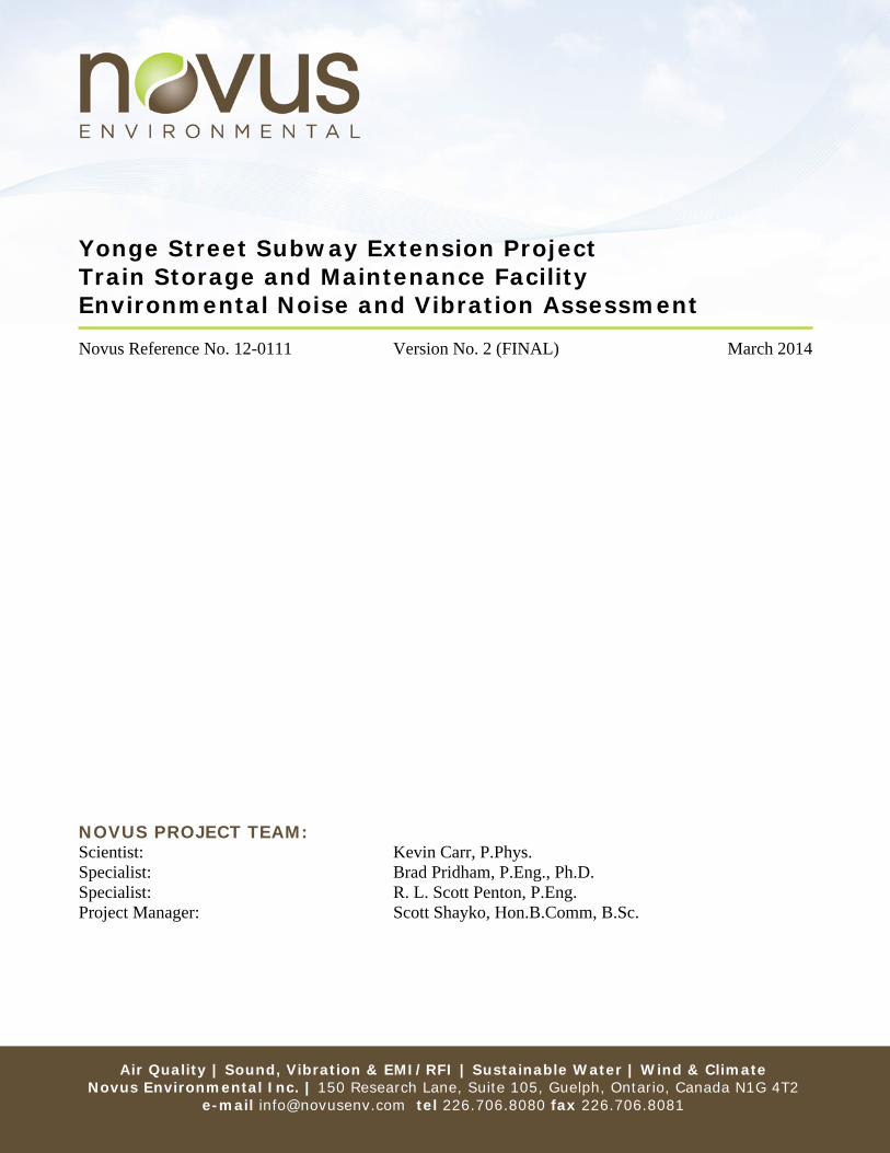
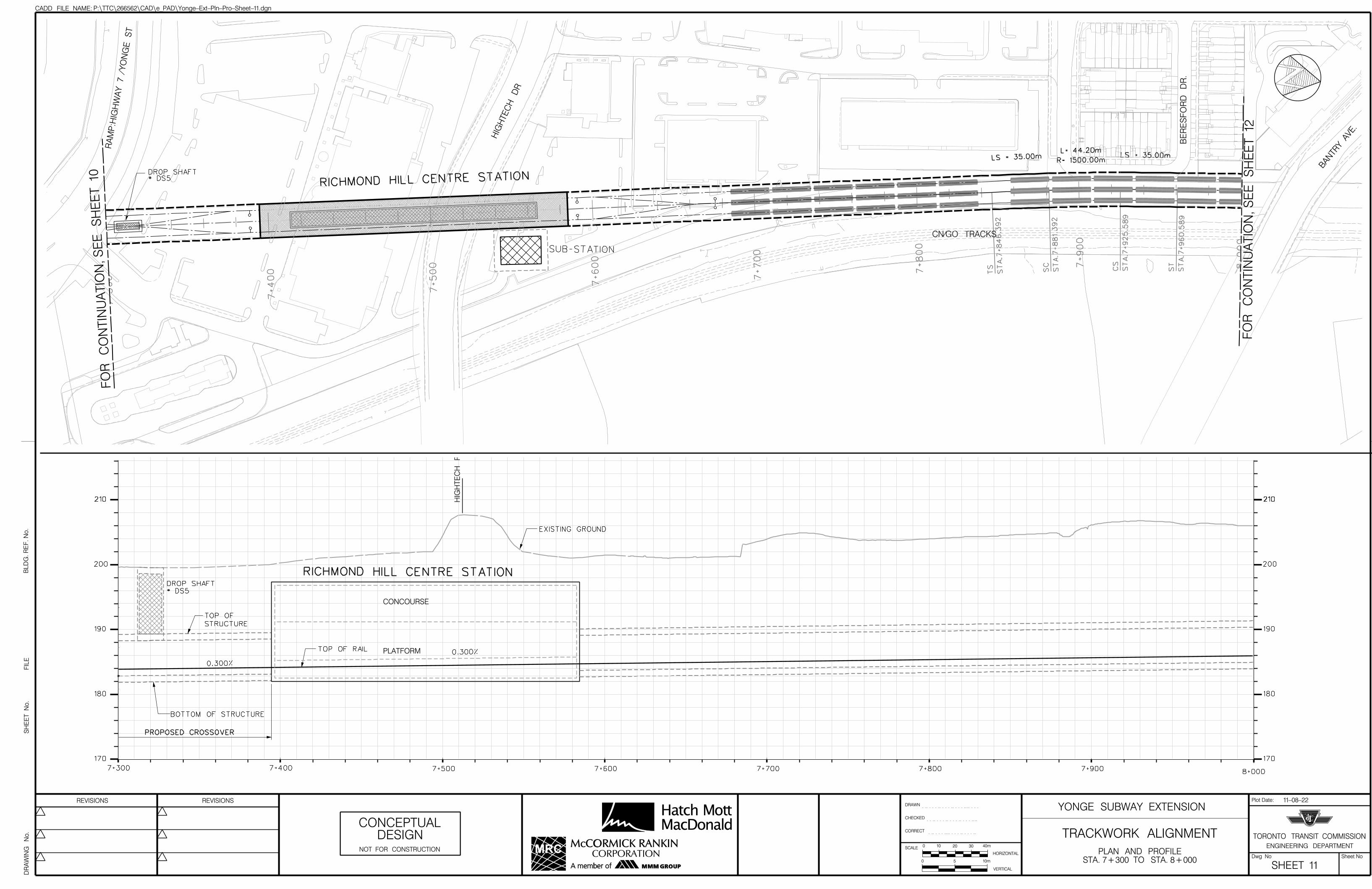
1.1.1 Planning Requirements and Design Considerations Primary maintenance for the Yonge Subway Extension will continue to be at the Wilson Yard located south of Downsview Station. However, overnight train storage will be provided in the area of Richmond Hill Centre Station and within an underground train storage facility where light-duty maintenance and cleaning of the subway vehicles will occur. Several alternatives were developed for the storage facility, including options which extended under Yonge Street north of the Langstaff Station, under the Commuter Parking Lot within the hydro corridor, and extending easterly within the hydro corridor north of Highway 7. Several alternatives were also developed which extended the subway line north of Richmond Hill Centre Station. Based on a high-level screening, a preferred alternative has been selected. The study area, including the preferred alternative footprint is shown in Figure 1. Detailed drawings showing the preferred alternative are included in Appendix A.
1.1.2 Facility Operations The following operational requirements were compiled following several meetings with TTC Subway Operations:
The facility will be below grade/enclosed and will be used for overnight storage and light maintenance interior cleaning and repairs, as well as off-peak storage (i.e. trains are not expected to deadhead to any other yards on YUS during off-peaks);
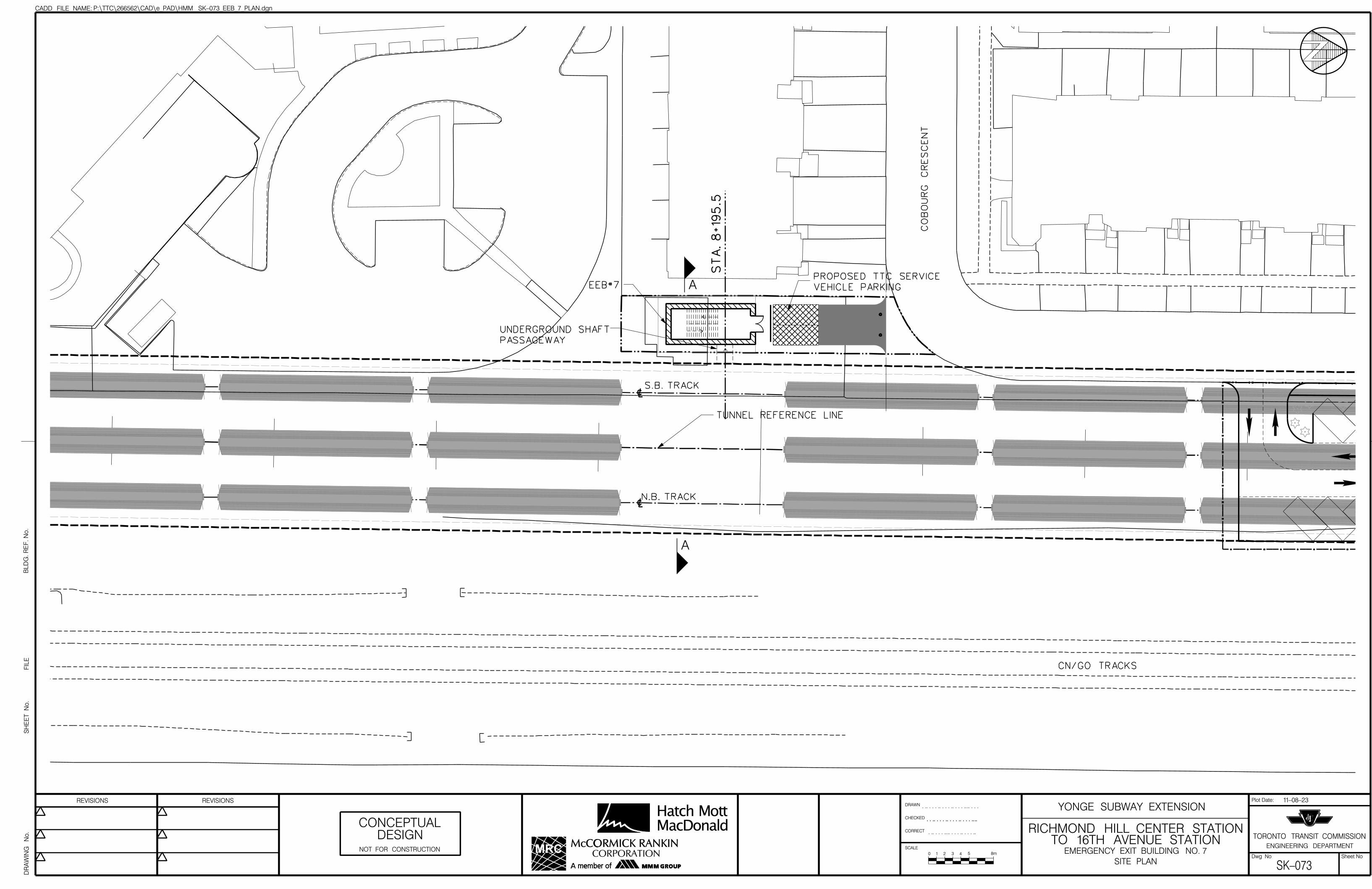
Maintenance crew will access/egress the underground facility from the Richmond Hill Centre Station Platform or from EEB #8 provided at the north end of the train storage facility;
Trains entering revenue service will be delivered by maintenance crew to the south end of the Richmond Hill Centre Station platform to be picked up by the operator, and
The facility will be staffed overnight to perform preventative maintenance diagnostic checks (self-diagnostics) and to provide a permanent presence (overnight security) in the facility.
March 2014 Environmental Noise and Vibration Assessment
Novus Environmental | 2
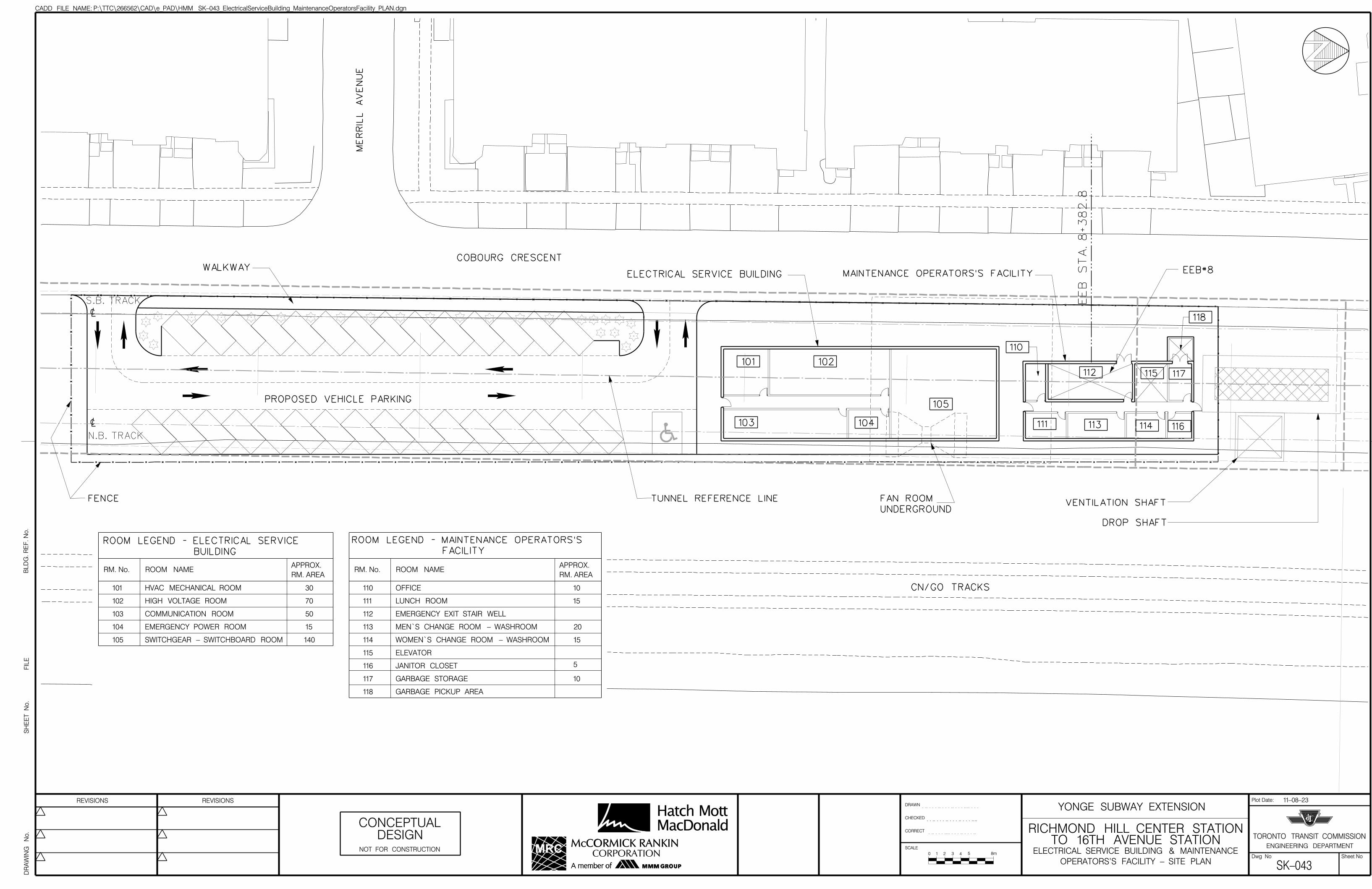
An assessment of the traction power and electrical requirements for the train storage facility has identified the need for an Electrical Service Building including a high voltage room, communication room, emergency power room, HVAC mechanical room and a switchgear-switchboard room. An assessment of the ventilation requirements for the Yonge Subway extension including the train storage facility has identified the need for an emergency ventilation fan, a fan room and a ventilation shaft to be located at the north end of the train storage facility. 1.2 Key Features within the Study Area The proposed subway line and TSMF within the study area will be underground, with two buildings aboveground (EEB8 / Maintenance Operator Facility and the Electrical Service Building). The TSMF will extend approximately 20 m underground, just to the west of the existing CN / GO Richmond Hill rail line. Key features within the study area are shown in Figure 1. 2.0 Noise and Vibration Assessment Criteria The noise and vibration criteria used in this assessment are based on protocols developed by the Ministry of the Environment (MOE) and Toronto Transit Commission (TTC) for previous transit system expansions (MOE/TTC 1993, MOE 1995). Additional criteria for ground-borne noise impacts were developed based on criteria from the U.S. Federal Transit Authority (FTA). Details on the guidelines are provided below. 2.1 Noise from Subway Surface Operations No surface subway operations are anticipated in the study area. Therefore, surface transportation noise has not been considered. 2.2 Noise from “Stationary” Operations The TSMF and associated ventilation shafts / HVAC are considered to be “Ancillary Facilities” under the MOE / TTC guidelines. The TSMF will have an HVAC system for station comfort ventilation, and an emergency fire ventilation system to supply air to the stations and tunnel system. TTC Design Manual DM-0403-00 (TTC 1994) sets out requirements for ancillary equipment in public areas. Noise from “Ancillary Equipment” (excluding emergency ventilation fans) should not exceed 60 dBA at 1 m distance in all public areas. In addition, MOE Publication NPC-300 (MOE 2013) noise guidelines apply for these facilities. These guidelines state that the 1-hour average sound level from the equipment (Leq (1-hr) values measured in dBA), must meet the following limits at all off-site noise sensitive points of reception:
Environmental Noise and Vibration Assessment March 2014
Novus Environmental | 3
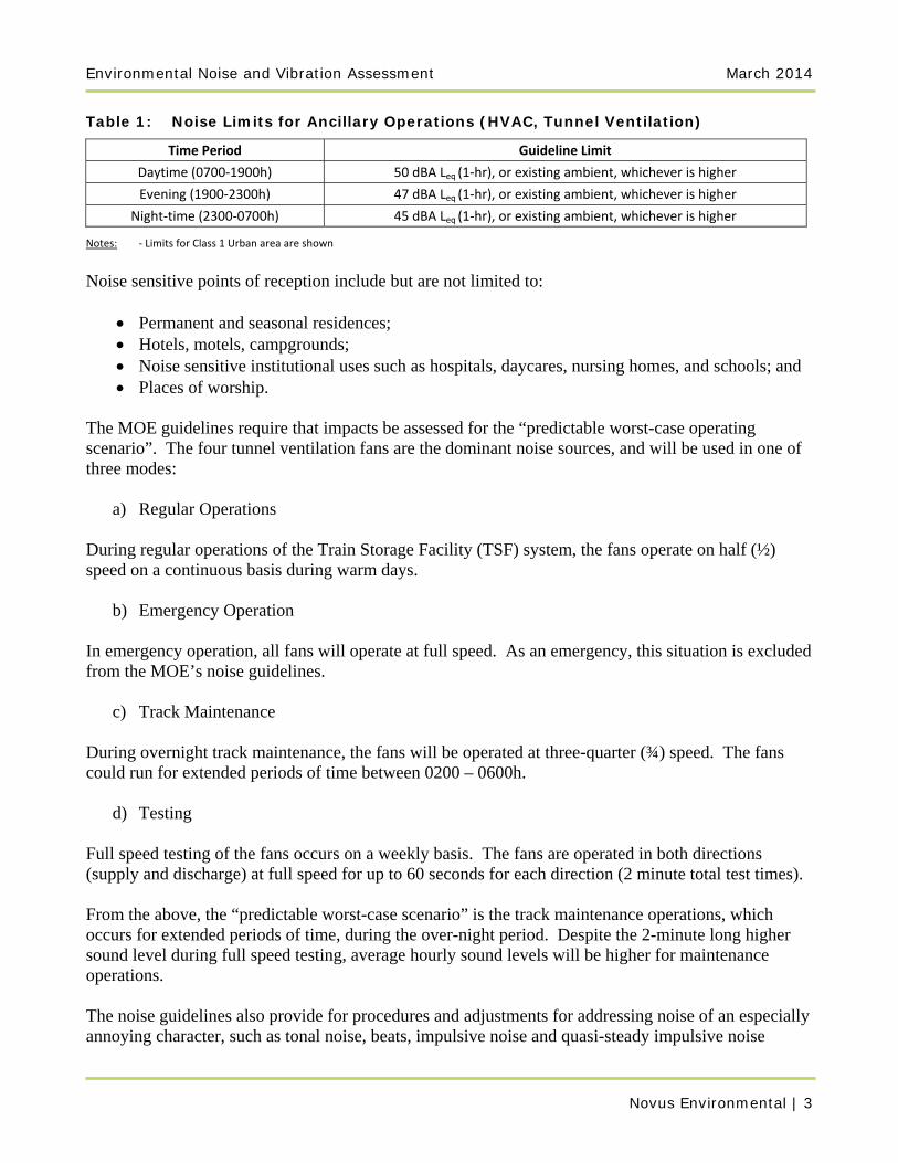
Table 1: Noise Limits for Ancillary Operations (HVAC, Tunnel Ventilation)
Time Period Guideline Limit
Daytime (0700‐1900h) 50 dBA Leq (1‐hr), or existing ambient, whichever is higher
Evening (1900‐2300h) 47 dBA Leq (1‐hr), or existing ambient, whichever is higher
Night‐time (2300‐0700h) 45 dBA Leq (1‐hr), or existing ambient, whichever is higher
Notes: ‐ Limits for Class 1 Urban area are shown
Noise sensitive points of reception include but are not limited to:
Permanent and seasonal residences; Hotels, motels, campgrounds; Noise sensitive institutional uses such as hospitals, daycares, nursing homes, and schools; and Places of worship.
The MOE guidelines require that impacts be assessed for the “predictable worst-case operating scenario”. The four tunnel ventilation fans are the dominant noise sources, and will be used in one of three modes:
a) Regular Operations During regular operations of the Train Storage Facility (TSF) system, the fans operate on half (½) speed on a continuous basis during warm days.
b) Emergency Operation In emergency operation, all fans will operate at full speed. As an emergency, this situation is excluded from the MOE’s noise guidelines.
c) Track Maintenance
During overnight track maintenance, the fans will be operated at three-quarter (¾) speed. The fans could run for extended periods of time between 0200 – 0600h.
d) Testing Full speed testing of the fans occurs on a weekly basis. The fans are operated in both directions (supply and discharge) at full speed for up to 60 seconds for each direction (2 minute total test times). From the above, the “predictable worst-case scenario” is the track maintenance operations, which occurs for extended periods of time, during the over-night period. Despite the 2-minute long higher sound level during full speed testing, average hourly sound levels will be higher for maintenance operations. The noise guidelines also provide for procedures and adjustments for addressing noise of an especially annoying character, such as tonal noise, beats, impulsive noise and quasi-steady impulsive noise
March 2014 Environmental Noise and Vibration Assessment
Novus Environmental | 4
(MOE 1977 a,b). Based on the generic sound data provided for the tunnel ventilation fans, sound from the ventilation fans will likely be tonal in nature. In accordance with Publication NPC-104 guidelines, a + 5 dB penalty has been applied in predicting noise impacts from these sources (MOE 1978). 2.3 Vibration from Subway Operations
2.3.1 Residential Ground-borne vibration from subway operations is addressed under the MOE/ TTC Protocols. Criteria are provided for maximum vibration levels outside of the premises of the receptor (outside of the foundation). Similar to noise, the point of assessment is any outdoor point on the property more than 15 m from the track centreline. Vibration is measured in terms of root-mean-squared (rms) vibration velocity in units of mm/s. Only vertical axis vibration is included in the assessment. For subway systems, this is the dominant direction of vibration excitation. The guideline limit for vibration is 0.10 mm/s rms. When vibration levels are predicted to exceed this threshold, then mitigation measures need to be investigated and implemented if they are technically, economically, and administratively feasible. In terms of human perception, a 0.10 mm/s vibration velocity level is just perceptible for most people.
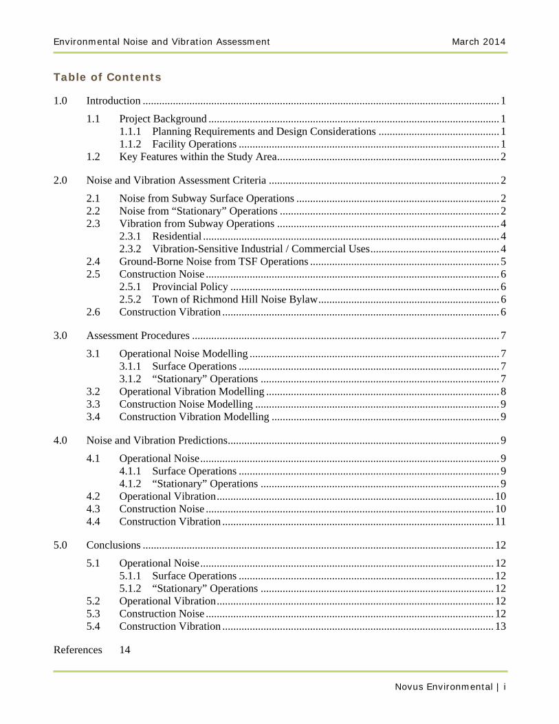
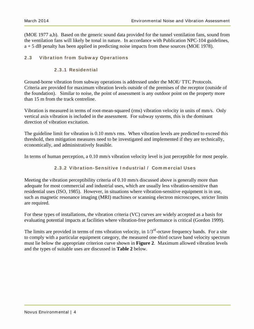
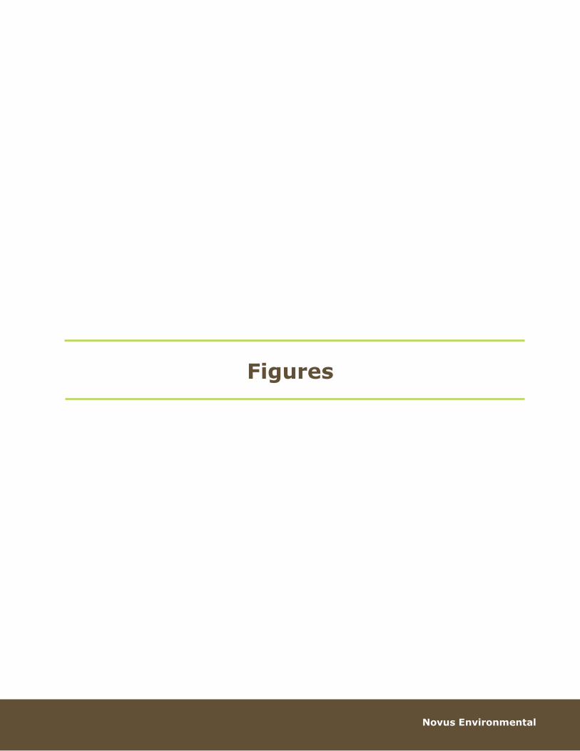
2.3.2 Vibration-Sensitive Industrial / Commercial Uses Meeting the vibration perceptibility criteria of 0.10 mm/s discussed above is generally more than adequate for most commercial and industrial uses, which are usually less vibration-sensitive than residential uses (ISO, 1985). However, in situations where vibration-sensitive equipment is in use, such as magnetic resonance imaging (MRI) machines or scanning electron microscopes, stricter limits are required. For these types of installations, the vibration criteria (VC) curves are widely accepted as a basis for evaluating potential impacts at facilities where vibration-free performance is critical (Gordon 1999). The limits are provided in terms of rms vibration velocity, in 1/3rd-octave frequency bands. For a site to comply with a particular equipment category, the measured one-third octave band velocity spectrum must lie below the appropriate criterion curve shown in Figure 2. Maximum allowed vibration levels and the types of suitable uses are discussed in Table 2 below.
Environmental Noise and Vibration Assessment March 2014
Novus Environmental | 5
Table 2: Vibration Criteria for Vibration Sensitive Uses
Criterion Curve (See Figure 1)
Maximum Allowable Vibration Level Above
8 Hz (mm/s., rms)
Description of Use
Workshop (ISO 2613)
0.800 Distinctly perceptible vibration. Appropriate for general industrial uses.
Office (ISO 2613)
0.400 Perceptible vibration. Appropriate for offices and non‐sensitive areas.
Residence, Day (ISO 2613)
0.200 Barely perceptible vibration. Appropriate to sleep areas in most instances. Probably adequate for computer equipment, probe test equipment and low‐power (to 20X) microscopes.
Operating Theatre/ Limit of Human Perception (ISO 2613)
0.100
Adopted for Residential Uses (overall vibration) in this Assessment (MOE/TTC) Vibration is imperceptible. Suitable for sensitive sleep areas. Suitable in most instances for microscopes to 100X and for other equipment of low sensitivity.
VC‐A 0.051 Adequate in most instances for optical microscopes to 400X, microbalances, optical balances, proximity and projection aligners, etc.
VC‐B 0.025 An appropriate standard for optical microscopes to 1000X, inspection and lithography equipment (including steppers) to 3 micron line widths.
VC‐C 0.013 A good standard for most lithography and inspection equipment to 1 micron detail size.
VC‐D 0.006 Suitable in most instances for the most demanding equipment including electron microscopes (TEMs and SEMs) and E‐Beam systems, operating to the limits of their capability.
VC‐E 0.003 Suitable in most instances for the most demanding equipment including electron microscopes (TEMs and SEMs) and E‐Beam systems, operating to the limits of their capability.
Notes: ‐ Adopted from Gordon, 1999. ‐ Levels are measured in 1/3rd‐octave bands between 8 Hz and 100 Hz.
‐ Maximum allowable vibration levels below 8 Hz increase at 2v per doubling of frequency (where v is the allowed rms velocity), unless the equipment incorporates pneumatic isolation. For example, the limit at 4 Hz for VC‐A equipment is (2 x 50 at 8 Hz) = 100 mm/s rms,
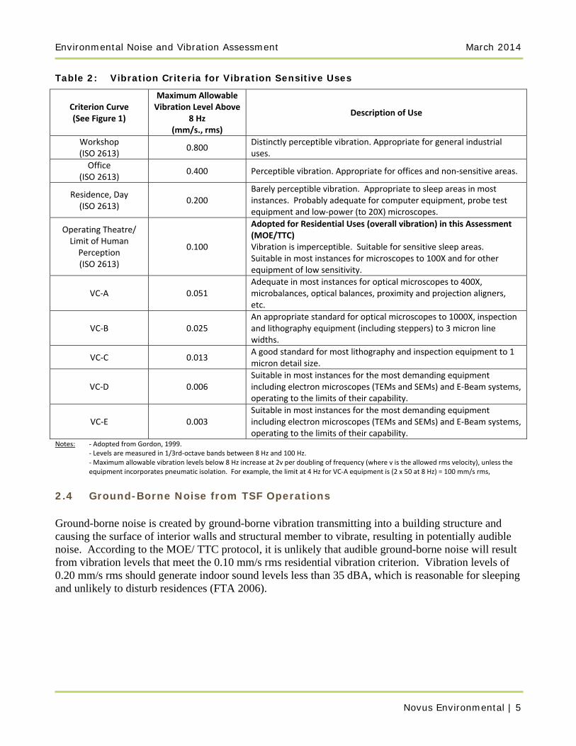
2.4 Ground-Borne Noise from TSF Operations Ground-borne noise is created by ground-borne vibration transmitting into a building structure and causing the surface of interior walls and structural member to vibrate, resulting in potentially audible noise. According to the MOE/ TTC protocol, it is unlikely that audible ground-borne noise will result from vibration levels that meet the 0.10 mm/s rms residential vibration criterion. Vibration levels of 0.20 mm/s rms should generate indoor sound levels less than 35 dBA, which is reasonable for sleeping and unlikely to disturb residences (FTA 2006).
March 2014 Environmental Noise and Vibration Assessment
Novus Environmental | 6
2.5 Construction Noise
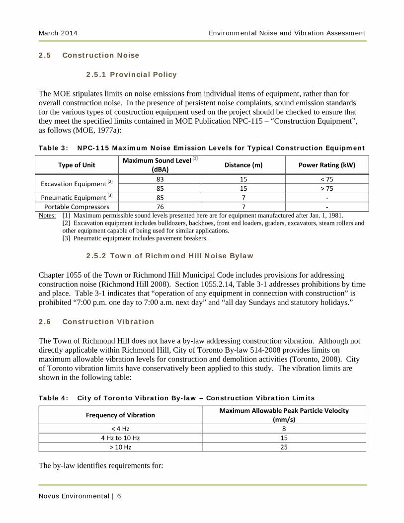
2.5.1 Provincial Policy The MOE stipulates limits on noise emissions from individual items of equipment, rather than for overall construction noise. In the presence of persistent noise complaints, sound emission standards for the various types of construction equipment used on the project should be checked to ensure that they meet the specified limits contained in MOE Publication NPC-115 – “Construction Equipment”, as follows (MOE, 1977a): Table 3: NPC-115 Maximum Noise Emission Levels for Typical Construction Equipment
Type of Unit Maximum Sound Level [1]
(dBA) Distance (m) Power Rating (kW)
Excavation Equipment [2] 83 15 < 75
85 15 > 75
Pneumatic Equipment [3] 85 7 ‐
Portable Compressors 76 7 ‐ Notes: [1] Maximum permissible sound levels presented here are for equipment manufactured after Jan. 1, 1981. [2] Excavation equipment includes bulldozers, backhoes, front end loaders, graders, excavators, steam rollers and
other equipment capable of being used for similar applications. [3] Pneumatic equipment includes pavement breakers.
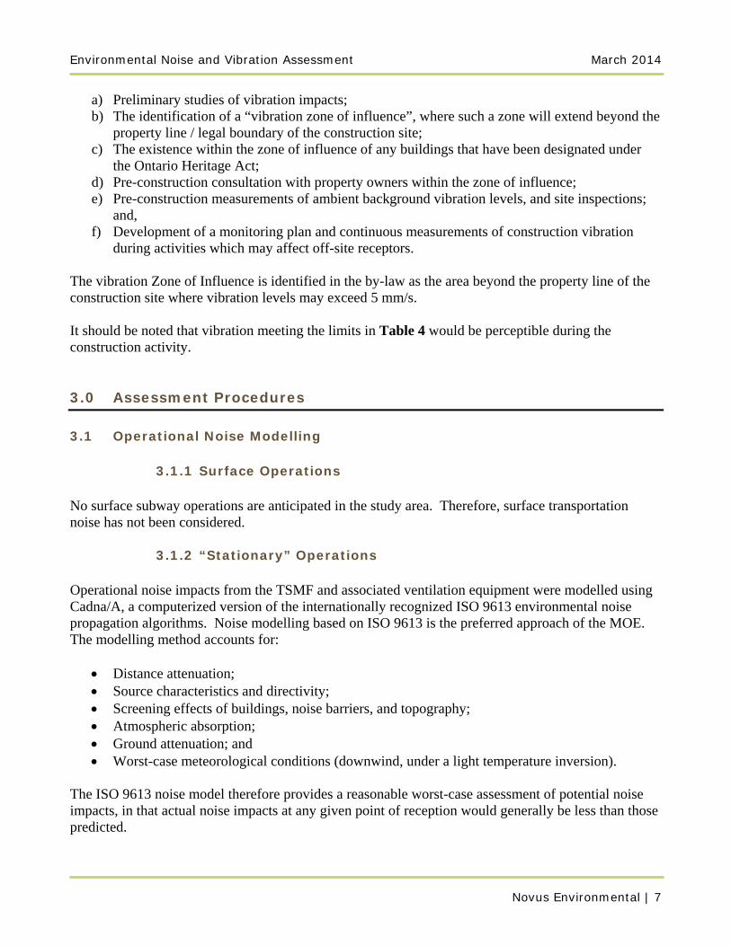
2.5.2 Town of Richmond Hill Noise Bylaw Chapter 1055 of the Town or Richmond Hill Municipal Code includes provisions for addressing construction noise (Richmond Hill 2008). Section 1055.2.14, Table 3-1 addresses prohibitions by time and place. Table 3-1 indicates that “operation of any equipment in connection with construction” is prohibited “7:00 p.m. one day to 7:00 a.m. next day” and “all day Sundays and statutory holidays.” 2.6 Construction Vibration The Town of Richmond Hill does not have a by-law addressing construction vibration. Although not directly applicable within Richmond Hill, City of Toronto By-law 514-2008 provides limits on maximum allowable vibration levels for construction and demolition activities (Toronto, 2008). City of Toronto vibration limits have conservatively been applied to this study. The vibration limits are shown in the following table:
Table 4: City of Toronto Vibration By-law – Construction Vibration Limits
Frequency of Vibration Maximum Allowable Peak Particle Velocity
(mm/s)
< 4 Hz 8
4 Hz to 10 Hz 15
> 10 Hz 25
The by-law identifies requirements for:
Environmental Noise and Vibration Assessment March 2014
Novus Environmental | 7
a) Preliminary studies of vibration impacts; b) The identification of a “vibration zone of influence”, where such a zone will extend beyond the
property line / legal boundary of the construction site; c) The existence within the zone of influence of any buildings that have been designated under
the Ontario Heritage Act; d) Pre-construction consultation with property owners within the zone of influence; e) Pre-construction measurements of ambient background vibration levels, and site inspections;
and, f) Development of a monitoring plan and continuous measurements of construction vibration
during activities which may affect off-site receptors. The vibration Zone of Influence is identified in the by-law as the area beyond the property line of the construction site where vibration levels may exceed 5 mm/s. It should be noted that vibration meeting the limits in Table 4 would be perceptible during the construction activity. 3.0 Assessment Procedures 3.1 Operational Noise Modelling
3.1.1 Surface Operations No surface subway operations are anticipated in the study area. Therefore, surface transportation noise has not been considered.
3.1.2 “Stationary” Operations Operational noise impacts from the TSMF and associated ventilation equipment were modelled using Cadna/A, a computerized version of the internationally recognized ISO 9613 environmental noise propagation algorithms. Noise modelling based on ISO 9613 is the preferred approach of the MOE. The modelling method accounts for:
Distance attenuation; Source characteristics and directivity; Screening effects of buildings, noise barriers, and topography; Atmospheric absorption; Ground attenuation; and Worst-case meteorological conditions (downwind, under a light temperature inversion).
The ISO 9613 noise model therefore provides a reasonable worst-case assessment of potential noise impacts, in that actual noise impacts at any given point of reception would generally be less than those predicted.
March 2014 Environmental Noise and Vibration Assessment
Novus Environmental | 8
As described in ISO 9613-2, ground factor values that represent the effect of ground absorption on sound levels range between 0 and 1. Based on the specific site conditions, the ground factor values used in the modelling were a ground factor value of 0 for acoustically hard surfaces, such as asphalt and concrete, with absorptive areas (grass, trees, etc.) drawn in as local areas of ground absorption equal to 1. A default temperate of 10 ºC and 70 % relative humidity, typical of average Ontario conditions, were also used.
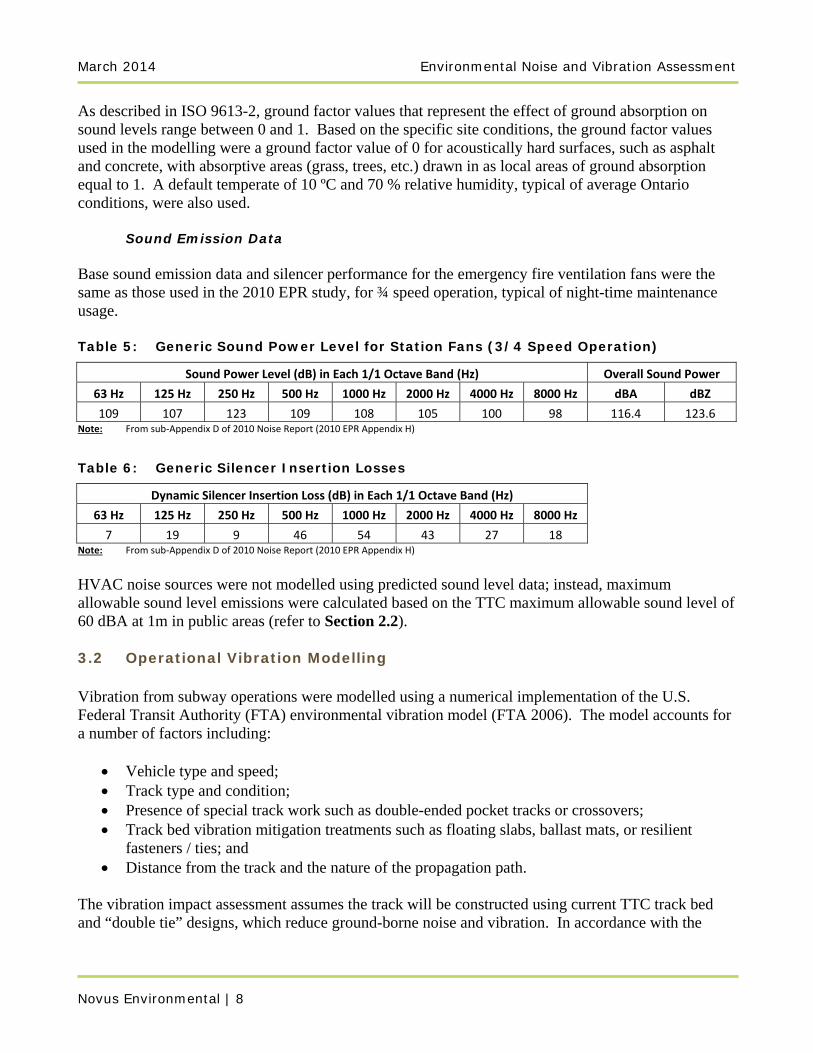
Sound Emission Data Base sound emission data and silencer performance for the emergency fire ventilation fans were the same as those used in the 2010 EPR study, for ¾ speed operation, typical of night-time maintenance usage. Table 5: Generic Sound Power Level for Station Fans (3/4 Speed Operation)
Sound Power Level (dB) in Each 1/1 Octave Band (Hz) Overall Sound Power
63 Hz 125 Hz 250 Hz 500 Hz 1000 Hz 2000 Hz 4000 Hz 8000 Hz dBA dBZ
109 107 123 109 108 105 100 98 116.4 123.6 Note: From sub‐Appendix D of 2010 Noise Report (2010 EPR Appendix H)
Table 6: Generic Silencer Insertion Losses
Dynamic Silencer Insertion Loss (dB) in Each 1/1 Octave Band (Hz)
63 Hz 125 Hz 250 Hz 500 Hz 1000 Hz 2000 Hz 4000 Hz 8000 Hz
7 19 9 46 54 43 27 18 Note: From sub‐Appendix D of 2010 Noise Report (2010 EPR Appendix H)
HVAC noise sources were not modelled using predicted sound level data; instead, maximum allowable sound level emissions were calculated based on the TTC maximum allowable sound level of 60 dBA at 1m in public areas (refer to Section 2.2). 3.2 Operational Vibration Modelling Vibration from subway operations were modelled using a numerical implementation of the U.S. Federal Transit Authority (FTA) environmental vibration model (FTA 2006). The model accounts for a number of factors including:
Vehicle type and speed; Track type and condition; Presence of special track work such as double-ended pocket tracks or crossovers; Track bed vibration mitigation treatments such as floating slabs, ballast mats, or resilient
fasteners / ties; and Distance from the track and the nature of the propagation path.
The vibration impact assessment assumes the track will be constructed using current TTC track bed and “double tie” designs, which reduce ground-borne noise and vibration. In accordance with the
Environmental Noise and Vibration Assessment March 2014
Novus Environmental | 9
MOE/TTC guidelines, the assessment also assumes the vehicles are in good operating condition, with minimal wheel flats, operating on well-maintained rail, with minimal rail corrugation. Operational vibration impacts were estimated assuming no coupling losses related to transmission from ground to building. In practice, vibration levels inside a residence are lower than those measured outside the building at grade due to attenuation from the foundation. However, MOE/TTC guidelines require vibration criteria to be met outside the residence, at grade. Coupling losses for a standard wood-framed house have the potential to lead to vibration impacts approximately 2 times lower than those outside of the structure. 3.3 Construction Noise Modelling Similar to operational noise impacts from the site ventilation equipment, noise impacts from construction activity were modelled using a software implementation of the internationally recognized ISO 9613 environmental noise propagation algorithms. The potential impacts from the generic types of equipment anticipated to be in use were predicted. 3.4 Construction Vibration Modelling Vibration impacts from surface construction equipment were predicted based on levels for generic types of construction equipment measured at various distances from the source, published in the literature (Wiss 1981, FTA 2006). This was used to identify a “zone of influence” per City of Toronto Noise Bylaw requirements. 4.0 Noise and Vibration Predictions 4.1 Operational Noise
4.1.1 Surface Operations No surface subway operations are anticipated in the study area. Therefore, surface transportation noise has not been considered.
4.1.2 “Stationary” Operations Stationary noise sources have been assessed cumulatively. Cumulative noise impacts include ventilation noise and noise from HVAC in the mechanical rooms of the electrical and access buildings. The number, size and location of required HVAC equipment at the MSF is unknown at this time. However, the HVAC is expected to be vented to a public area. As part of the detailed design, the equipment should be selected such that the noise level of the equipment at 1 m from the vent does not exceed 60 dBA.
March 2014 Environmental Noise and Vibration Assessment
Novus Environmental | 10
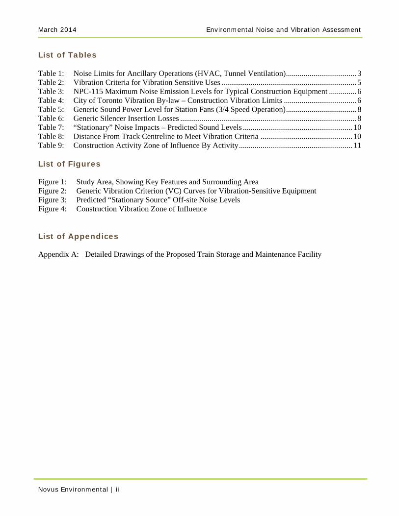
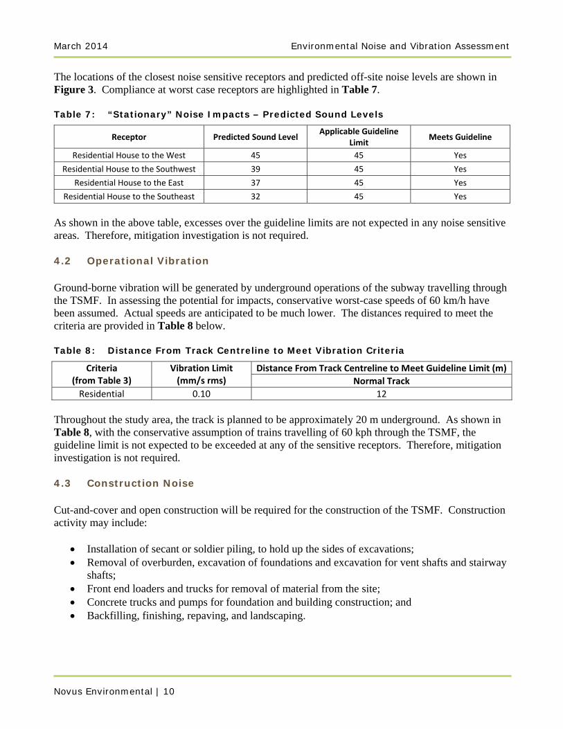
The locations of the closest noise sensitive receptors and predicted off-site noise levels are shown in Figure 3. Compliance at worst case receptors are highlighted in Table 7. Table 7: “Stationary” Noise Impacts – Predicted Sound Levels
Receptor Predicted Sound Level Applicable Guideline
Limit Meets Guideline
Residential House to the West 45 45 Yes
Residential House to the Southwest 39 45 Yes
Residential House to the East 37 45 Yes
Residential House to the Southeast 32 45 Yes
As shown in the above table, excesses over the guideline limits are not expected in any noise sensitive areas. Therefore, mitigation investigation is not required. 4.2 Operational Vibration Ground-borne vibration will be generated by underground operations of the subway travelling through the TSMF. In assessing the potential for impacts, conservative worst-case speeds of 60 km/h have been assumed. Actual speeds are anticipated to be much lower. The distances required to meet the criteria are provided in Table 8 below. Table 8: Distance From Track Centreline to Meet Vibration Criteria
Criteria (from Table 3)
Vibration Limit (mm/s rms)
Distance From Track Centreline to Meet Guideline Limit (m)
Normal Track
Residential 0.10 12
Throughout the study area, the track is planned to be approximately 20 m underground. As shown in Table 8, with the conservative assumption of trains travelling of 60 kph through the TSMF, the guideline limit is not expected to be exceeded at any of the sensitive receptors. Therefore, mitigation investigation is not required. 4.3 Construction Noise Cut-and-cover and open construction will be required for the construction of the TSMF. Construction activity may include:
Installation of secant or soldier piling, to hold up the sides of excavations; Removal of overburden, excavation of foundations and excavation for vent shafts and stairway
shafts; Front end loaders and trucks for removal of material from the site; Concrete trucks and pumps for foundation and building construction; and Backfilling, finishing, repaving, and landscaping.
Environmental Noise and Vibration Assessment March 2014
Novus Environmental | 11
Construction noise levels will vary over time as the activities at the site change. Worst-case sound levels from construction activity, at the closest noise-sensitive receptors, will range from:
75 dBA to 104 dBA, for removal of original surface material (including a +10 dB annoyance penalty applied to the hoe ram / mounted impact hammer).
73 dBA to 96 dBA, for pile driving. 74 dBA to 85 dBA, for general excavation and removal of material.
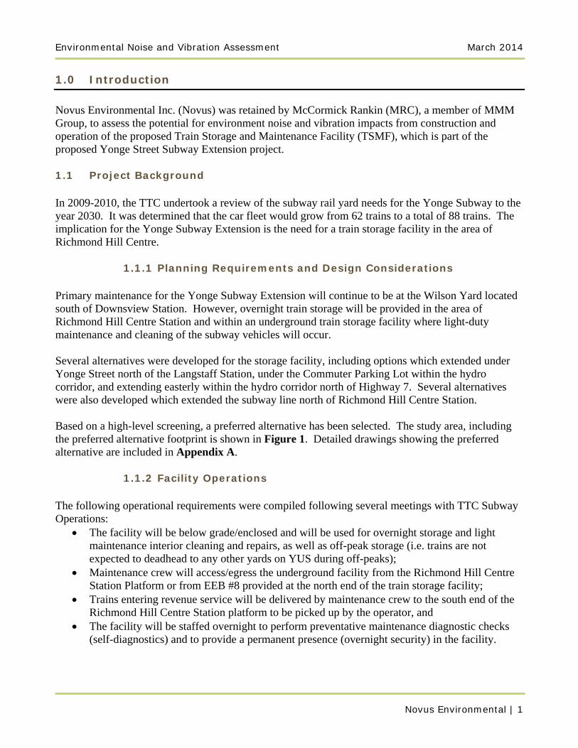
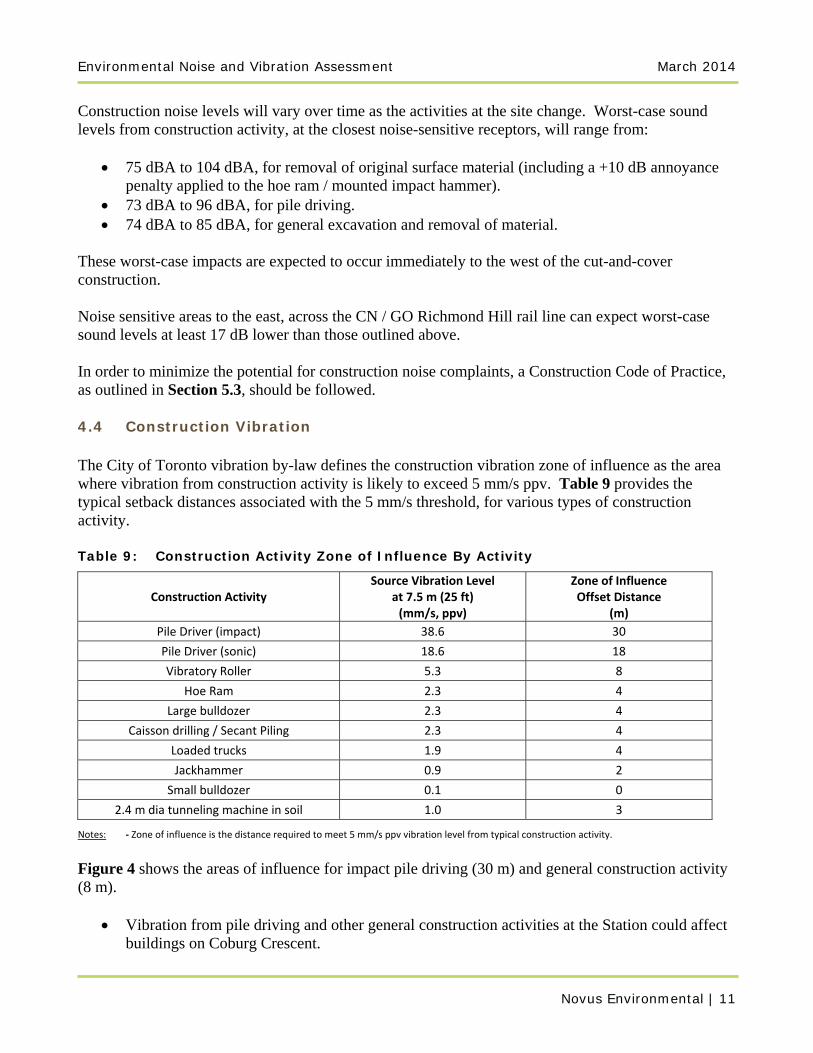
These worst-case impacts are expected to occur immediately to the west of the cut-and-cover construction. Noise sensitive areas to the east, across the CN / GO Richmond Hill rail line can expect worst-case sound levels at least 17 dB lower than those outlined above. In order to minimize the potential for construction noise complaints, a Construction Code of Practice, as outlined in Section 5.3, should be followed. 4.4 Construction Vibration The City of Toronto vibration by-law defines the construction vibration zone of influence as the area where vibration from construction activity is likely to exceed 5 mm/s ppv. Table 9 provides the typical setback distances associated with the 5 mm/s threshold, for various types of construction activity. Table 9: Construction Activity Zone of Influence By Activity
Construction Activity Source Vibration Level
at 7.5 m (25 ft) (mm/s, ppv)
Zone of Influence Offset Distance
(m)
Pile Driver (impact) 38.6 30
Pile Driver (sonic) 18.6 18
Vibratory Roller 5.3 8
Hoe Ram 2.3 4
Large bulldozer 2.3 4
Caisson drilling / Secant Piling 2.3 4
Loaded trucks 1.9 4
Jackhammer 0.9 2
Small bulldozer 0.1 0
2.4 m dia tunneling machine in soil 1.0 3
Notes: ‐ Zone of influence is the distance required to meet 5 mm/s ppv vibration level from typical construction activity.
Figure 4 shows the areas of influence for impact pile driving (30 m) and general construction activity (8 m).
Vibration from pile driving and other general construction activities at the Station could affect buildings on Coburg Crescent.
March 2014 Environmental Noise and Vibration Assessment
Novus Environmental | 12
Under the terms of the City Vibration By-law, pre-construction consultation, vibration monitoring, and site inspections would likely be required, and monitoring will be required during construction. Although not required within the Town of Richmond Hill, construction vibration monitoring is recommended. 5.0 Conclusions 5.1 Operational Noise
5.1.1 Surface Operations No surface subway operations are anticipated in the study area. Therefore, surface transportation noise has not been considered.
5.1.2 “Stationary” Operations Based on the generic sound power emission data and silencer insertion loss data used in this assessment (Section 3.1.2), the emergency fire ventilation fans are expected to meet the applicable MOE NPC-300 guideline limits at all noise sensitive locations. Based on the TTC requirement for all ancillary equipment to meet 60 dBA at 1 m in all public spaces, no adverse impacts are expected from the HVAC equipment to be located at the surface electrical service building. Should noise emissions or operations vary significantly from those outlined above, noise impacts should be reassessed to assure compliance with all relevant legislative requirements. 5.2 Operational Vibration Vibration levels due to operations are expected to be below the MOE/TTC guideline limit of 0.10 mm/s rms at all locations. Therefore, no adverse vibration impacts from normal operations are anticipated. 5.3 Construction Noise Construction noise impacts are temporary in nature, and generally unavoidable. Although for some periods and types of work construction noise will be noticeable, with adequate controls impacts can be minimized. This section of the report provides an evaluation of noise impacts from construction, and recommends a Code of Practice to minimize impacts. To minimize the potential for construction noise impacts, it is recommended that provisions be written into the contract documentation for the contractor, as outlined below:
Construction should be limited to the time periods allowed by the locally applicable by-laws (no operations between 1900h-0700h, on Sundays, or on Statutory Holidays, except in the case
Environmental Noise and Vibration Assessment March 2014
Novus Environmental | 13
of emergencies). If construction activities are required outside of these hours, the Contractor must seek permits / exemptions directly from the Town of Richmond Hill in advance.
There should be explicit indication that Contractors are expected to comply with all applicable requirements of the contract and local noise by-laws. Enforcement of noise control by-laws is the responsibility of the Municipality for all work done by Contractors.
All equipment should be properly maintained to limit noise emissions. As such, all construction equipment should be operated with effective muffling devices that are in good working order.
The Contract documents should contain a provision that any initial noise complaint will trigger verification that the general noise control measures agreed to, are in effect.
In the presence of persistent noise complaints, all construction equipment should be verified to comply with MOE NPC-115 guidelines, as outlined in Section 2.5.1.
In the presence of persistent complaints and subject to the results of a field investigation, alternative noise control measured may be required, where reasonably available. In selecting appropriate noise control and mitigation measures, consideration should be given to the technical, administrative and economic feasibility of the various alternatives.
Any blasting works should be designed to meet any applicable overpressure and vibration limits established by the MOE in Publication NPC-119 and by the MTO in OPSS 120.
Since the sound levels from the construction activity are anticipated to be quite high during some periods, and the site is located adjacent to public space, construction hoarding/temporary fences are recommended where feasible.
5.4 Construction Vibration Under the terms of the City of Toronto Vibration By-law, pre-construction consultation, vibration monitoring, and site inspections would likely be required, and monitoring would be required during construction. Although not required within the Town of Richmond Hill, construction vibration monitoring is recommended. Zones of influence for construction activities (the area where vibration levels may exceed 5 mm/s ppv) are shown in the construction vibration sections of this report. Care should be taken where structures are located within the zone of influence.
March 2014 Environmental Noise and Vibration Assessment
Novus Environmental | 14
References Federal Transit Administration, 2006, Transit Noise and Vibration Impact Assessment Gordon, Colin, 1999, Generic Vibration Criteria for Vibration-Sensitive Equipment, Colin Gordon & Associates, 411 Borel Avenue Suite 425, San Mateo, CA 94402 USA International Organization for Standardization, 1985, ISO 2631-1:1985, Mechanical vibration and shock -- Evaluation of human exposure to whole-body vibration -- Part 1: General requirements International Organization for Standardization, 1996, ISO 9613-2: Acoustics – Attenuation of Sound During Propagation Outdoors Part 2: General Method of Calculation Ontario Ministry of the Environment (MOE), 1977a, Model Municipal Noise Control Bylaw, which includes Publication NPC-115 – Construction Equipment Ontario Ministry of the Environment (MOE), 1977b, Model Municipal Noise Control Bylaw, which includes Publication NPC-119 – Noise From Blasting Ontario Ministry of the Environment (MOE), 1977c, Publication NPC-104: Model Municipal Noise Control By-Law Ontario Ministry of the Environment (MOE), 1989, Ontario Road Noise Analysis Method for Environment and Transportation (ORNAMENT) Ontario Ministry of the Environment (MOE), 1990, Sound from Trains Environmental Analysis Method (STEAM) Ontario Ministry of the Environment (MOE), 2013, Publication NPC-300: Environmental Noise Guideline: Stationary and Transportation Sources – Approval and Planning Ontario Ministry of the Environment (MOE) / Toronto Transit Commission (TTC), 1993, Protocol for Noise and Vibration Assessment for Proposed Yonge-Spadina Subway Loop Ontario Ministry of Transportation (MTO), 2003, Ontario Provincial Standard Specification OPSS 120: General Specification for the Use of Explosives Toronto Transit Commission (TTC), 1994, DM-0403-00 Acoustics Section Town of Richmond Hill, 2008, Municipal Code, Chapter 1055: Noise Wiss, J.F., 1981, Construction vibrations: State-of-the-Art, American Society of Civil Engineers, ASCE Journal of Geotechnical Engineering, Vol. 107, No. GT2, pp. 167-181.
Novus Environmental
Figures

This page intentionally left blank for 2-sided printing purposes
Figure No. 1
TrueNorth
Scale: 1: 5,000
150 Research Lane, Suite 105Guelph, ON, Canada, N1G 4T2
t. 226.706.8080 f.226.706.8081www.novusenv.com
Study Area Showing Key Features and Surrounding Area
Date: 13/05/30
File No.: 12-0111
Yonge Street Subway Extension ProjectTrain Storage and Maintenance Facility Drawn By: KAC
Beyond Scope of Current Study:Future Richmond Hill Subway Station
EEB8 / Maintenance Operator Facility
Electrical Service Building
EEB7
Figure No. 2 Scale: n/a
150 Research Lane, Suite 105Guelph, ON, Canada, N1G 4T2
t. 226.706.8080 f.226.706.8081www.novusenv.com
Generic Vibration Criterion (VC) Curves for Vibration-Sensitive Equipment
Date: 13/05/30
File No.: 12-0111
Yonge Street Subway Extension ProjectTrain Storage and Maintenance Facility Drawn By: KAC
10
1
0.1
0.01
0.001
Vibration Velocity (mm/s, rms)
Workshop (ISO)
Office (ISO)
Residential Day (ISO)
MOE/TTC, Operating Theatre (ISO)
VC‐A, 50 micrometers
VC‐B, 25 micrometers
VC‐C, 12.5 micrometers
VC‐D, 6 micrometers
VC‐B, 3 micrometers
Notes:• Residential criterion adopted for this assessment is MOE / TTC Protocol value of 0.100 mm/s rms for overall vibration (all
frequencies combined). Assuming impacts mainly occur in a narrow frequency range above 8 Hz (as is typical), then the overall limit would be equivalent to the 1/3rd‐octave band frequency limit shown in the chart.
• General office space and industrial workshop spaces can tolerate greater vibration levels than residential spaces (ISO 2631).
• Specific vibration‐sensitive industrial or commercial uses may require stricter limits, depending in the nature of the operation. The Vibration Criteria (VC) curves shown provide generic criteria for a number of vibration sensitive uses (see text).
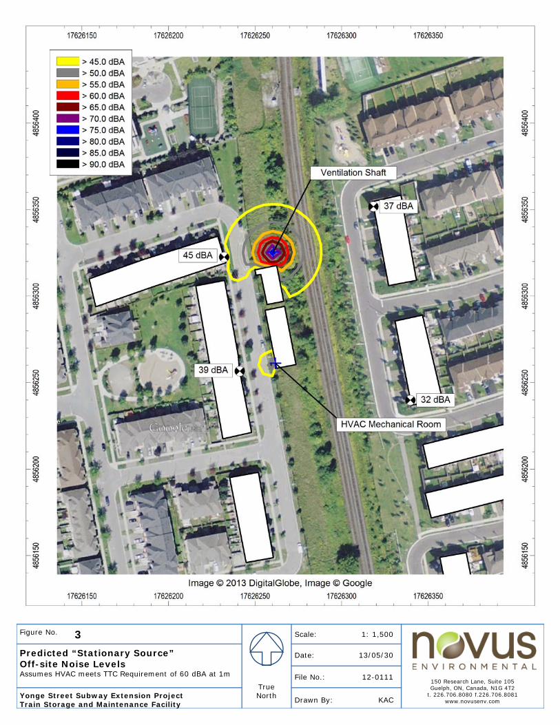
Figure No. 3
TrueNorth
Scale: 1: 1,500
150 Research Lane, Suite 105Guelph, ON, Canada, N1G 4T2
t. 226.706.8080 f.226.706.8081www.novusenv.com
Predicted “Stationary Source” Off-site Noise LevelsAssumes HVAC meets TTC Requirement of 60 dBA at 1m
Date: 13/05/30
File No.: 12-0111
Yonge Street Subway Extension ProjectTrain Storage and Maintenance Facility Drawn By: KAC
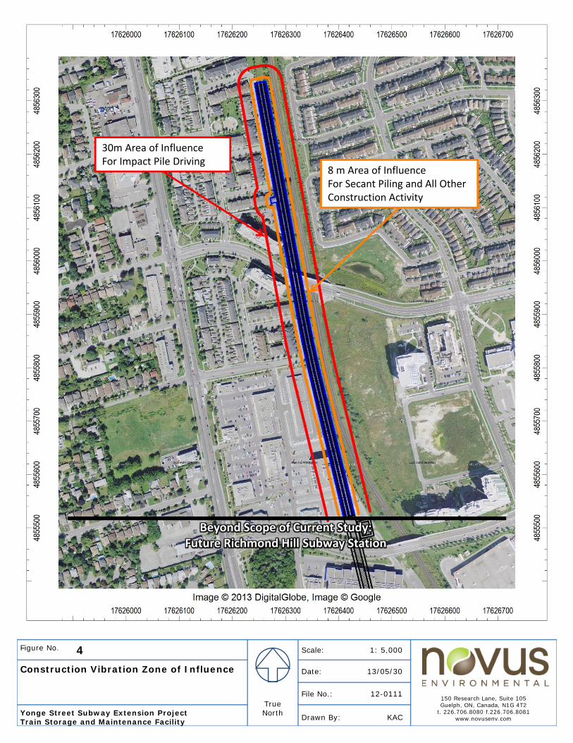
Figure No. 4
TrueNorth
Scale: 1: 5,000
150 Research Lane, Suite 105Guelph, ON, Canada, N1G 4T2
t. 226.706.8080 f.226.706.8081www.novusenv.com
Construction Vibration Zone of Influence Date: 13/05/30
File No.: 12-0111
Yonge Street Subway Extension ProjectTrain Storage and Maintenance Facility Drawn By: KAC
30m Area of InfluenceFor Impact Pile Driving
8 m Area of InfluenceFor Secant Piling and All Other Construction Activity
Beyond Scope of Current Study:Future Richmond Hill Subway Station
Novus Environmental
Appendix A

This page intentionally left blank for 2-sided printing purposes
CONCOURSE
PLATFORM
RICHMOND HILL CENTRE STATION
HIG
HTE
CH
RD
EXISTING GROUND
BOTTOM OF STRUCTURE
TOP OF RAIL0.300%
0.300%
PROPOSED CROSSOVER
DROP SHAFT
# DS5
TOP OF
STRUCTURE
ENGINEERING DEPARTMENT
REVISIONS
FIL
EB
LD
G. R
EF.
No.
DRAWN
CHECKED
CORRECT
SCALE
DR
AWIN
G
No.
SH
EET
No.
TORONTO TRANSIT COMMISSION
Dwg. No.
Plot Date:
P:\TTC\266562\CAD\e_PAD\Yonge-Ext-Pln-Pro-Sheet-11.dgnCADD FILE NAME:
REVISIONS 11-08-22
Sheet No.
NOT FOR CONSTRUCTION
CONCEPTUALDESIGN
YONGE SUBWAY EXTENSION
7+700 7+800 7+9008+000
7+300 7+400 7+500 7+600
170
180
190
200
210210
170
180
190
200
210210210210
7+800
RICHMOND HILL CENTRE STATION
7+300
7+4
00
7+500
7+600
7+7
00SUB-STATION
DROP SHAFT # DS5
LS = 35.00mL= 44.20m
R= 1500.00mLS = 35.00m
7+900
8+000
TS
ST
A.7
+84
6.3
92
SC
ST
A.7
+881.3
92
CS
ST
A.7
+92
5.5
89
ST
ST
A.7
+960.5
89
HIG
HTEC
H
DR
RA
MP:HIG
HW
AY 7 / Y
ON
GE ST
BANTR
Y AVE.
CN/GO TRACKS
BE
RESF
OR
D
DR.
BAFFIN CRT
0 10 20 30 40m
HORIZONTAL
VERTICAL
TRACKWORK ALIGNMENT
FO
R
CO
NTIN
UATIO
N, SEE S
HEET 10
PLAN AND PROFILESTA. 7+300 TO STA. 8+000
SHEET 11
MRC0 5 10m
FO
R
CO
NTIN
UATIO
N, SEE S
HEET 12
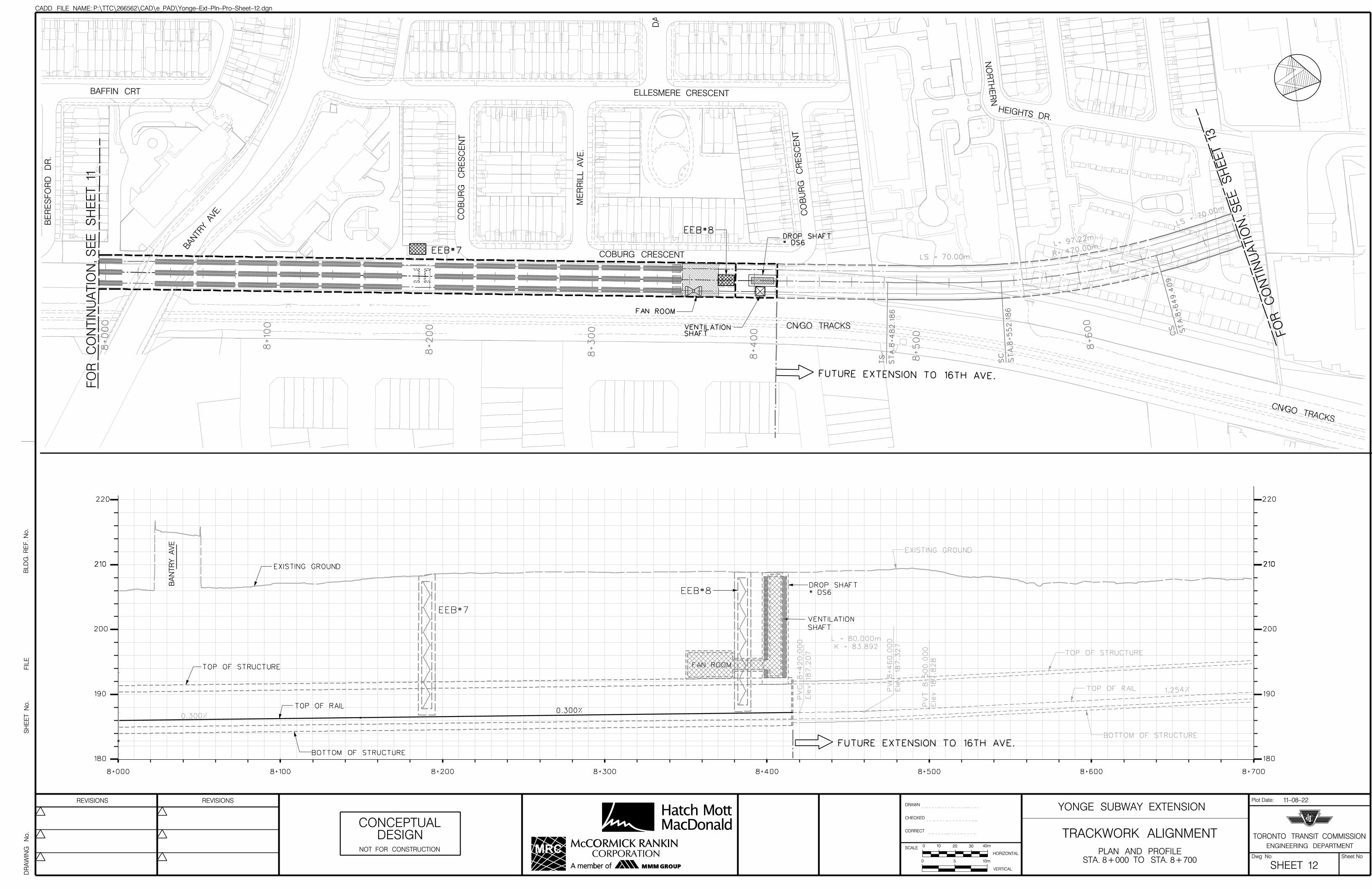
0.300%
1.254%
TOP OF STRUCTURE
BOTTOM OF STRUCTURE
TOP OF RAIL
EXISTING GROUND
BA
NTR
Y
AVE
TOP OF STRUCTURE
BOTTOM OF STRUCTURE
TOP OF RAIL
EXISTING GROUND
0.300%
FAN ROOM
PV
C
8+4
20.0
00
Ele
v 187.2
07
PVI 8
+4
60.0
00
Ele
v 187.3
27
PV
T
8+500.0
00
Ele
v 187.8
28
L = 80.000m
K = 83.892
VENTILATION
SHAFT
EEB#7
EEB#8
FUTURE EXTENSION TO 16TH AVE.
DROP SHAFT
# DS6
ENGINEERING DEPARTMENT
REVISIONS
FIL
EB
LD
G. R
EF.
No.
DRAWN
CHECKED
CORRECT
SCALE
DR
AWIN
G
No.
SH
EET
No.
TORONTO TRANSIT COMMISSION
Dwg. No.
Plot Date:
P:\TTC\266562\CAD\e_PAD\Yonge-Ext-Pln-Pro-Sheet-12.dgnCADD FILE NAME:
REVISIONS 11-08-22
Sheet No.
NOT FOR CONSTRUCTION
CONCEPTUALDESIGN
YONGE SUBWAY EXTENSION
8+000 8+100 8+200 8+300 8+400 8+500 8+600 8+700
180
190
200
210210
220
180
190
200
210210210210
220
8+000
8+100
8+200
8+300
8+4
00
LS = 70.00m
8+500
TS
ST
A.8
+4
82.1
86
L= 97.22
m
R= 470.00
m
8+600
SC
ST
A.8
+552.1
86
LS = 7
0.00m
8+700
CS ST
A.8
+64
9.4
09
FUTURE EXTENSION TO 16TH AVE.
VENTILATION SHAFT
FAN ROOM
EEB#8DROP SHAFT # DS6
EEB#7BANTR
Y AVE.
HEIGHTS DR.
CN/GO TRACKS
CN/GO TRACKS
NO
RTH
ER
N
BE
RESF
OR
D
DR.
BAFFIN CRT
COBURG CRESCENT
ELLESMERE CRESCENT
DALE
MO
UN
T
GATE
CO
BU
RG
CR
ES
CE
NT
CO
BU
RG
CR
ES
CE
NT
ME
RRIL
L A
VE.
0 10 20 30 40m
HORIZONTAL
VERTICAL
TRACKWORK ALIGNMENT
FO
R
CO
NTIN
UATIO
N, SEE S
HEET 11
PLAN AND PROFILESTA. 8+000 TO STA. 8+700
SHEET 12
MRC0 5 10m
FO
R
CO
NTIN
UATIO
N, SEE S
HEET 13
ENGINEERING DEPARTMENT
REVISIONS
FIL
EB
LD
G. R
EF.
No.
DRAWN
CHECKED
CORRECT
SCALE
DR
AWIN
G
No.
SH
EET
No.
TORONTO TRANSIT COMMISSION
Dwg. No.
Plot Date:
P:\TTC\266562\CAD\e_PAD\HMM SK-043_ElectricalServiceBuilding_MaintenanceOperatorsFacility_PLAN.dgnCADD FILE NAME:
REVISIONS 11-08-23
Sheet No.
NOT FOR CONSTRUCTION
CONCEPTUALDESIGN
YONGE SUBWAY EXTENSION
EEB#8
CN/GO TRACKS
COBOURG CRESCENT
VENTILATION SHAFT
0 1 2 3 4 5 8m
ROOM NAMERM. No.RM. AREA
APPROX.
30
15
101 HVAC MECHANICAL ROOM
HIGH VOLTAGE ROOM
COMMUNICATION ROOM
EMERGENCY POWER ROOM
70
50
140
102
103
104
105
ROOM NAMERM. No.RM. AREA
APPROX.
10
20
110
15111
112
113
114
OFFICE
LUNCH ROOM
ELEVATOR115
116
117
JANITOR CLOSET
GARBAGE STORAGE
GARBAGE PICKUP AREA
EMERGENCY EXIT STAIR WELL
15
5
10
118
101 102
103 104
105
111 113 114 116
110
112 115 117
118
ME
RRIL
L
AV
EN
UE
FAN ROOM
UNDERGROUND
DROP SHAFT
WALKWAY
FENCE
ROOM LEGEND - ELECTRICAL SERVICE
BUILDING
ELECTRICAL SERVICE BUILDING
N.B. TRACK
C
C
S.B. TRACK
TUNNEL REFERENCE LINE
WOMEN‘S CHANGE ROOM - WASHROOM
MEN‘S CHANGE ROOM - WASHROOM
SWITCHGEAR - SWITCHBOARD ROOM
MAINTENANCE OPERATORS’S FACILITY
ELECTRICAL SERVICE BUILDING & MAINTENANCE
OPERATORS’S FACILITY - SITE PLAN
ROOM LEGEND - MAINTENANCE OPERATORS’S
FACILITY
SK-043
PROPOSED VEHICLE PARKING
RICHMOND HILL CENTER STATION TO 16TH AVENUE STATION
EE
B
ST
A.
8+3
82.8
MRC
ENGINEERING DEPARTMENT
REVISIONS
FIL
EB
LD
G. R
EF.
No.
DRAWN
CHECKED
CORRECT
SCALE
DR
AWIN
G
No.
SH
EET
No.
TORONTO TRANSIT COMMISSION
Dwg. No.
Plot Date:
P:\TTC\266562\CAD\e_PAD\HMM SK-073_EEB_7_PLAN.dgnCADD FILE NAME:
REVISIONS 11-08-23
Sheet No.
NOT FOR CONSTRUCTION
CONCEPTUALDESIGN
YONGE SUBWAY EXTENSION
EEB#7 PROPOSED TTC SERVICE
VEHICLE PARKING
EMERGENCY EXIT BUILDING NO. 7
SITE PLAN
CN/GO TRACKS
CO
BO
UR
G
CR
ES
CE
NT
0 1 2 3 4 5 8m
A
A
UNDERGROUND SHAFT
PASSAGEWAY
N.B. TRACKC
CS.B. TRACK
TUNNEL REFERENCE LINE
SK-073
RICHMOND HILL CENTER STATION TO 16TH AVENUE STATION
ST
A.
8+195.5
MRC


