139 AMPI Ch4
50
39-A-04-00-00-00A-001H-A 39-A-AMPI-00-P Air vehicle maintenance planning information Chapter 04 Airworthiness limitations E.A.S.A. approved Third issue: 2013-04-05 This issue replaces second issue dated 2006-08-22, change 10 dated 2010-08-09 NOTE TO READERS AW139 and AB139 are two names for the same product. They identify two batches of aircraft manufactured in conformity with a unique Type Certificate Data Sheet. Where not specifically declared, the content of this document is applicable to both AW139 and AB139 helicopters.
-
Upload
brucie-bruce -
Category
Documents
-
view
120 -
download
5
description
Agusta, Maintenance, Manual
Transcript of 139 AMPI Ch4

39-A-04-00-00-00A-001H-A
39-A-AMPI-00-P
Air vehicle maintenance planning information
Chapter 04
Airworthiness limitations
E.A.S.A. approved
Third issue: 2013-04-05
This issue replaces second issue dated 2006-08-22, change 10 dated 2010-08-09
NOTE TO READERS
AW139 and AB139 are two names for the same product.They identify two batches of aircraft manufactured inconformity with a unique Type Certificate Data Sheet.Where not specifically declared, the content of thisdocument is applicable to both AW139 and AB139helicopters.
39-A-04-00-00-00A-001H-A
39-A-AMPI-00-P
THIS PAGE INTENTIONALLY LEFT BLANK

Effectivity: All 04 LOEP
2013-04-05 Page 1
39-A-AMPI-00-P
C = Changed module N = New moduleD = Deleted module R = Revised module
(*) The asterisks identify the modules changed, revised, added or deleted with this change
List of effective pagesDates of issue and changes are:
Third issue 2013-04-05
The Third Issue of this chapter includes the modules that follow:
Document identifier Page Date Effectivity
39-A-04-00-00-00A-000A-A 4 C 2013-04-05 * All
39-A-04-00-00-00A-000H-A 2 C 2013-01-07 * All
39-A-04-10-00-00A-000A-A 14 C 2013-03-19 * All
39-A-04-20-00-00A-000A-A 8 C 2013-01-07 * All
39-A-04-30-00-00A-000A-A 12 C 2013-01-07 * All

Effectivity: All 04 LOEP
2013-04-05 Page 2
39-A-AMPI-00-P
THIS PAGE INTENTIONALLY LEFT BLANK

39-A-AMPI-00-P
04 CRPage 1
2013-04-05
Change record
ChangeNo.
Incorporateddate by (signature)
ChangeNo.
Incorporateddate by (signature)
1 26
2 27
3 28
4 29
5 30
6 31
7 32
8 33
9 34
10 35
11 36
12 37
13 38
14 39
15 40
16 41
17 42
18 43
19 44
20 45
21 46
22 47
23 48
24 49
25 50

THIS PAGE INTENTIONALLY LEFT BLANK
04 CRPage 2
2013-04-05
39-A-AMPI-00-P

39-A-AMPI-00-P
Effectivity: All 04 HI
2013-04-05 Page 1
Highlights
The listed changes are introduced with Third Issue
Document Identifier Reason for update
39-A-04-00-00-00A-000A-A CHANGED - Added approval of Third issue
39-A-04-00-00-00A-000H-A CHANGED - Updated para 1
39-A-04-10-00-00A-000A-A CHANGED - Added Note to para 1, ref. RL15A, RL33B thru RL33F, Note1 thru Note 3 to Table 2. Added ref. RL15A to Table 5 and example toTable 7. Changed the retirement life of ref. RL012 thru RL012B, RL34and Note 1 to Table 4. Deleted ref. RL049 thru RL051 to Table 2 andRL012 thru RL012B to Table 3 and Table 7. Updated para “Guidelines”.
39-A-04-20-00-00A-000A-A CHANGED - Updated para 3.4 and Note 2 to Table 2
39-A-04-30-00-00A-000A-A CHANGED - Updated para 2.4 - Moved ref. CM25-26 to CM32-01 - Added ref. CM30-07 and CM30-08.

39-A-AMPI-00-P
Effectivity: All 04 HI
2013-04-05 Page 2
THIS PAGE INTENTIONALLY LEFT BLANK

Effectivity: All 04 TOC
2013-04-05 Page 1
39-A-AMPI-00-P
Table of contents
Technical Name Information Name Document Identifier Effectivity
Airworthiness Authority approval General 39-A-04-00-00-00A-000A-A All
Airworthiness limitations General 39-A-04-00-00-00A-000H-A All
Retirement lives General 39-A-04-10-00-00A-000A-A All
Mandatory inspections General 39-A-04-20-00-00A-000A-A All
Certification maintenance requirements
General 39-A-04-30-00-00A-000A-A All

Effectivity: All 04 TOC
2013-04-05 Page 2
39-A-AMPI-00-P
THIS PAGE INTENTIONALLY LEFT BLANK

Effectivity: All 39-A-04-00-00-00A-000A-A
2013-04-05 Page 1
39-A-AMPI-00-P
39-A-04-00-00-00A-000A-AAirworthiness Authority approval – General
Originat or:-PB------
Table of contentsReferences ................................................................................................................................... 11 Record of Airworthiness Authority approvals ..................................................................... 1
List of tables1 References ......................................................................................................................... 12 Record of Airworthiness Authority approvals ..................................................................... 1
References
Description
1 Record of Airworthiness Authority approvalsRefer to Table 2.
Note The reported approval references are relevant to the content of Chapter 04 as a whole.The content that has changed is reported in the List of Effective Data Modules.
Table 2 Record of Airworthiness Authority approvals
Table 1 References
Data Module Title
No references
Revision number Subject E.A.S.A. approved
First Issue - - Approval No. 2004-7835
Dated 22 July 2004
Change 1 See Highlights (HI) page Approval No. 2005-2675
Dated 24 March 2005
Change 2 See Highlights (HI) page Approval No. EASA.R.C.01475
Dated 13 January 2006
Change 3 See Highlights (HI) page Approval No. EASA.R.A.01093
Dated 16 February 2006
Change 4 See Highlights (HI) page Approval No. EASA.R.C.01680
Dated 02 May 2006
Change 5 See Highlights (HI) page Approval No. EASA.R.C.01874
Dated 28 July 2006

Effectivity: All 39-A-04-00-00-00A-000A-A
2013-04-05 Page 2
39-A-AMPI-00-P
Second Issue See Highlights (HI) page Approval No. EASA.R.C.01901
Dated 22 August 2006
Change 1 See Highlights (HI) page Approval No. EASA.R.C.02125
Dated 18 June 2007
Approval No. EASA.R.C.02165
Dated 18 June 2007
Change 2 See Highlights (HI) page Approval No. EASA.R.C.02291
Dated 06 December 2007
Approval No. EASA.R.C.02518
Dated 06 December 2007
Approval No. EASA.R.C.02715
Dated 06 December 2007
Change 3 See Highlights (HI) page Approval No. EASA.R.C.02676
Dated 01 February 2008
Approval No. EASA.R.C.02751
Dated 01 February 2008
Change 4 See Highlights (HI) page Approval No. EASA.R.C02913
Dated 21 July 2008
Change 5 See Highlights (HI) page Approval No. EASA.R.C.02399
Dated 14 August 2008
Change 6 See Highlights (HI) page Approval No. EASA.R.C.03161
Dated 02 February 2009
Revision number Subject E.A.S.A. approved

Effectivity: All 39-A-04-00-00-00A-000A-A
2013-04-05 Page 3
39-A-AMPI-00-P
Change 7 See Highlights (HI) page Approval No. EASA.R.C.02159
Dated 24 July 2009
Approval No. EASA.R.C.02272
Dated 24 July 2009
Approval No. EASA.R.C.03183
Dated 24 July 2009
Approval No. EASA.R.C.03345
Dated 24 July 2009
Approval No. EASA.R.C.03346
Dated 24 July 2009
Change 8 See Highlights (HI) page Approval No. P-EASA.R.C.03182
Dated 28 September 2009
Change 9 See Highlights (HI) page Approval No. 10028921
Dated 19 February 2010
Approval No. 10028924
Dated 19 February 2010
Change 10 See Highlights (HI) page Approval No. 10031288
Dated 09 August 2010
Change 11 See Highlights (HI) page Approval No. 10035423
Dated 21 June 2011
Approval No. 10035424
Dated 21 June 2011
Approval No. 10035426
Dated 21 June 2011
Change 12 See Highlights (HI) page Approval No. 10036515
Dated 16 September 2011
Approval No. 10036518
Dated 16 September 2011
Revision number Subject E.A.S.A. approved

Effectivity: All 39-A-04-00-00-00A-000A-A
2013-04-05 Page 4
39-A-AMPI-00-P
End of data module
Change 13 See Highlights (HI) page Approval No. 10040465
Dated 05 July 2012
Approval No. 10040469, REV. 1
Dated 18 July 2012
Change 14 See Highlights (HI) page Approval No. 10041845
Dated 19 October 2012
Approval No. 10041847
Dated 19 October 2012
Third issue See Highlights (HI) page Approval No. 10044321
Dated 05 April 2013
Approval No. 10044323
Dated 05 April 2013
Approval No. 10044325
Dated 05 April 2013
Approval No. 10044326, Rev. 1
Dated 05 April 2013
Approval No. 10044328
Dated 05 April 2013
Revision number Subject E.A.S.A. approved

Effectivity: All 39-A-04-00-00-00A-000H-A
2013-01-07 Page 1
39-A-AMPI-00-P
End of data module
39-A-04-00-00-00A-000H-AAirworthiness limitations – General
Originat or:-PB------
Table of contentsReferences ................................................................................................................................... 11 Airworthiness limitations..................................................................................................... 12 Airworthiness limitations data modules .............................................................................. 13 Engine airworthiness limitations ......................................................................................... 1
List of tables1 References ......................................................................................................................... 1
References
Description
1 Airworthiness limitationsThis chapter identifies the airworthiness limitations for the AW139 helicopter approved byE.A.S.A. The Airworthiness Limitations Section is approved and variations must also be approved.
The airworthiness limitations section cannot be changed without approval.
2 Airworthiness limitations data modulesThe airworthiness limitations include the data modules that follow:
– The retirement lives (39-A-04-10-00-00A-000A-A)– The mandatory inspections (39-A-04-20-00-00A-000A-A)– The certification maintenance requirements (39-A-04-30-00-00A-000A-A).
3 Engine airworthiness limitationsRefer to the latest issue of the engine maintenance manual for the airworthiness limitationsapplicable to the Pratt & Whitney Canada PT6C-67C engine.
Note The Airworthiness Limitations, specified for any Part Number quoted in this Chapter04, apply also to all successive Part Numbers having the same first ten digits anddiffetent last two digits, unless otherwise specified.
Table 1 References
Data Module Title
39-A-04-10-00-00A-000A-A Retirement lives – General
39-A-04-20-00-00A-000A-A Mandatory inspections – General
39-A-04-30-00-00A-000A-A Certification maintenance requirements – General

Effectivity: All 39-A-04-00-00-00A-000H-A
2013-01-07 Page 2
39-A-AMPI-00-P
THIS PAGE INTENTIONALLY LEFT BLANK
Effectivity: All 39-A-04-10-00-00A-000A-A
2013-03-19 Page 1
39-A-AMPI-00-P
39-A-04-10-00-00A-000A-ARetirement lives – General
Originat or:-PB-----E-MAIL AW - CHPT04/21-12-2012 and 15-02-2013 -
Table of contentsReferences ................................................................................................................................... 11 Introduction......................................................................................................................... 12 Retirement lives - Affected parts ........................................................................................ 23 Terms and definitions of Table 2 ........................................................................................ 23.1 Reference (Ref).................................................................................................................. 23.2 Part..................................................................................................................................... 23.3 Part number........................................................................................................................ 23.4 Retirement life .................................................................................................................... 24 External Hoist Operation .................................................................................................... 95 External Load Operation .................................................................................................. 106 Operation above 6400 kg (MTOW) .................................................................................. 117 Guidelines ........................................................................................................................ 12
List of tables1 References ......................................................................................................................... 12 Retirement lives - List of affected parts .............................................................................. 33 CAT. A Training Operations - Life penalty factor................................................................ 84 Rotor Starting or Stopping with wind speed above 27 kts - Life penalty factor .................. 85 External Hoist Lift - Life penalty factor................................................................................ 96 External Load Operation - Life penalty factor................................................................... 107 Operation above 6400 kg (MTOW) - Life penalty factor................................................... 11
References
Description
1 IntroductionThe parts listed in the Table 2 must be mandatorily retired from service when the indicatedretirement life is reached. This also applies to all those non-serialized standard parts whichconnect the identified assembly / component.
All retirement lives are expressed in Flying Hours (FH), unless otherwise specified. Flying hoursare defined as those hours accumulated from take-off to landing.
The retirement lives of some parts are expressed in “landings” because their life is dependentupon the rotor start-stop cycles and the helicopter ground-air-ground cycles.
Note If the number of landings applicable to the component is not known throughout the entireservice life of the component, the number of landings shall be calculated multiplying thecomponent flight hours by a factor of 6.
If not differently specified, the retirement lives are based on the following assumptions:
Table 1 References
Data Module Title
No references

Effectivity: All 39-A-04-10-00-00A-000A-A
2013-03-19 Page 2
39-A-AMPI-00-P
– 800 landings in 100 flying hours, including 400 rotor start-stop cycles.– 20 percent of usage in CAT. A Training Operations, on yearly basis.– For External Load Operations: 6 External Load Cycles and 3 Landings per Flying Hour,
calculated on at least 100 FH basis– For External Hoist Operations: 1.65 Lift per Flying Hour, calculated on at least 100 FH basis.
In the event that the actual usage exceeds these assumptions, the Operator shall contact theManufacturer.
If parts with the same part number have been interchanged between different AW139 variants,the retirement life of the part must be restricted to the lowest value between those variants onwhich the part has been installed.
For the following parts the Operator shall maintain the relevant log card and contact theManufacturer prior to approaching the 40000 FH for confirmation of the applicability of theairworthiness instructions provided in this chapter:
– Fuselage Structure Assembly, part number 3P5300A00132.
2 Retirement lives - Affected partsRefer to Table 2.
3 Terms and definitions of Table 2
3.1 Reference (Ref)This column gives a reference [RL (Retirement Lives) plus a progressive number] which identifiesthe listed components.
3.2 PartThis column gives the part description.
3.3 Part numberThis column gives the part number.
3.4 Retirement lifeThis column gives the retirement life of the part. Unless specified differently, the retirement life itin flight hours.

Effectivity: All 39-A-04-10-00-00A-000A-A
2013-03-19 Page 3
39-A-AMPI-00-P
Table 2 Retirement lives - List of affected parts
Ref Part Part number Retirement life
RL001 Left Main Landing Gear Assembly (Liebherr landing gear installation)
3G3210V00133 21000 landings
Left Main Landing Gear Assembly (Liebherr landing gear installation)
3G3210V00135 50000 landings
Deleted
Right Main Landing Gear Assembly (Liebherr landing gear installation)
3G3210V00233 21000 landings
Right Main Landing Gear Assembly (Liebherr landing gear installation)
3G3210V00235 50000 landings
Deleted
RL002 Nose Landing Gear Assembly (Liebherr landing gear installation)
3G3220V00133 50000 landings
Deleted
RL002A Nose Landing Gear Assembly (Goodrich landing gear installation)
4G3220V00131 12500 landings
RL003 Main Retracting Actuator Assembly (Liebherr landing gear installation)
3G3230V00332 50000 landings
RL003A Main Retracting Actuator Assembly (Goodrich landing gear installation)
4G3230V00233 12500 landings
RL004 Nose Retracting Actuator Assembly (Liebherr landing gear installation)
3G3230V00132 50000 landings
RL004A Nose Retracting Actuator Assembly (Goodrich landing gear installation)
4G3230V00131 12500 landings
RL004B Left MLG Trailing Arm Assembly (Goodrich landing gear installation)
4G3210V00331 12500 landings
RL004C Right MLG Trailing Arm Assembly (Goodrich landing gear installation)
4G3210V00431 12500 landings
RL004D MLG Shock Absorber Assembly (Goodrich landing gear installation)
4G3210V00531 12500 landings
RL004E Forward Arm Assy (Goodrich landing gear installation)
4F3210A00131 12500 landings
RL005 TGB Fitting 3G5351A01151 7200
RL006 Tail Assembly 3G5350A00132 10000 FH or 32000 landings whichever comes first (Para 5)
RL007 Main Landing Gear LH Segment 3P5339A00332 80000 landings
Main Landing Gear RH Segment 3P5339A00432 80000 landings

Effectivity: All 39-A-04-10-00-00A-000A-A
2013-03-19 Page 4
39-A-AMPI-00-P
RL007A Rear Fuselage Assembly 3P5340A00132 32000 landings
RL007B Trailing Arm Pintle Pin (Goodrich landing gear installation)
3G5339A08351 11000 landings
RL008 Tailplane Attachment Fitting on Fin Upper 3G5351A01432 7600
Tailplane Attachment Fitting on Fin Upper 3G5351A01532 7600
RL009 Tailplane Attachment Fitting on Fin Lower 3G5351A07531 10600
RL010 Deleted
RL010A Rod End (Fin End) 3G5510A03931 4600 (Para 6)
RL010B Rod Sleeve 3G5510A04152 10000
RL010C Rod End (Tailplane End) 3G5510A04052 10000 (Para 6)
RL010D Tailplane Assembly 3G5510A00133 65000 (Para 6)
RL011 Main Landing Gear Actuator Bolt on Sponson Bracket
3G3210L00151 160000 landings
RL012 Main Rotor Blade Assembly 3G6210A00131 10000 (Table 4)
RL012A Main Rotor Blade Assembly with Heater Mat
4G6210A00132 6000 (Table 4)
RL012B Main Rotor Blade Assembly 3G6210A00134 20000 FH or 40000 landings or 5 years whichever comes first (Table 4) (Note 1)
RL013 Main Rotor Hub Assembly 3G6220A00332 46000 (Para 5)
RL014 Deleted
RL015 Main Rotor Rotating Swashplate 3G6230A00332 4800 (Para 4)
RL015A Main Rotor Rotating Swashplate Assy reworked
3G6206P01331 4800 (Para 4)
RL016 Main Rotor Scissors Attachment Flange Assembly
3G6220A00632 47450
RL016A Main Rotor Scissors Attachment Flange Assembly
3G6220A00633 Unlimited
RL017 Main Rotor Damper Bolt 3G6220A01251 51700
RL018 Main Rotor Elastomeric Bearing 3G6220V00153 100000 landings
Main Rotor Elastomeric Bearing 3G6220V00154 100000 landings
RL019 Upper Scissor Lever Assembly 3G6230A00832 14300
RL019A Deleted
RL019B Lower Scissor Lever Assembly 3G6230A00931 20100
Ref Part Part number Retirement life

Effectivity: All 39-A-04-10-00-00A-000A-A
2013-03-19 Page 5
39-A-AMPI-00-P
RL019C Upper Scissor Lever Assembly 3G6230A00834 Unlimited
RL019D Lower Scissor Lever Assembly 3G6230A00934 Unlimited
RL020 Deleted
RL021 MGB Case, Top Assembly 3G6320A01033 8800 FH or 23000 landings whichever comes first (Para 6)
MGB Case, Top Assembly 3G6320A01035 17000
RL022 MGB Shaft, Main Rotor 3G6320A01852 15300 FH or 54000 landings whichever comes first (Table 3) and (Para 4) and (Para 5)
RL023 MGB Case, Main Assembly 3G6320A02734 5000 FH or 27000 landings whichever comes first (Para 5)
MGB Case, Main Assembly 3G6320A02736 10000 FH or 77500 landings whichever comes first (Para 5)
RL024 MGB Upper Fitting 3G6330A00232 95800 landings (Para 6)
RL025 MGB Antitorque Beam 3G6330A00532 20000 FH or 63000 landings whichever comes first (Para 5)
RL026 Deleted
RL027 Deleted
RL028 Deleted
RL029 Deleted
RL030 Deleted
RL031 Deleted
RL032 Deleted
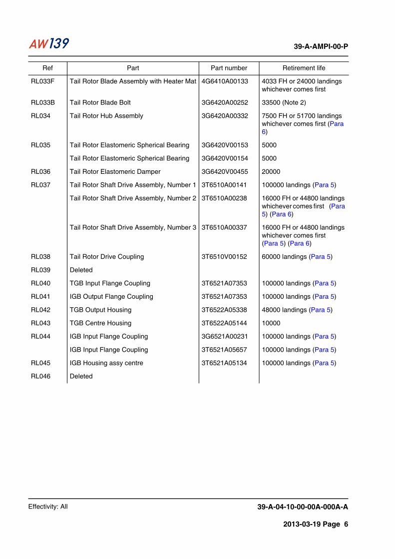
RL033 Tail Rotor Blade Assembly 3G6410A00131 10000
RL033C Tail Rotor Blade Assembly 3G6410A00132 1200 FH or 3200 landings whichever comes first
RL033D Tail Rotor Blade Assembly 3G6410A00133 10000 FH or 24000 landings whichever comes first (Note 3)
RL033A Tail Rotor Blade Assembly with Heater Mat 4G6410A00131 4033
RL033E Tail Rotor Blade Assembly with Heater Mat 4G6410A00132 1200 FH or 3200 landings whichever comes first
Ref Part Part number Retirement life
Effectivity: All 39-A-04-10-00-00A-000A-A
2013-03-19 Page 6
39-A-AMPI-00-P
RL033F Tail Rotor Blade Assembly with Heater Mat 4G6410A00133 4033 FH or 24000 landings whichever comes first
RL033B Tail Rotor Blade Bolt 3G6420A00252 33500 (Note 2)
RL034 Tail Rotor Hub Assembly 3G6420A00332 7500 FH or 51700 landings whichever comes first (Para 6)
RL035 Tail Rotor Elastomeric Spherical Bearing 3G6420V00153 5000
Tail Rotor Elastomeric Spherical Bearing 3G6420V00154 5000
RL036 Tail Rotor Elastomeric Damper 3G6420V00455 20000
RL037 Tail Rotor Shaft Drive Assembly, Number 1 3T6510A00141 100000 landings (Para 5)
Tail Rotor Shaft Drive Assembly, Number 2 3T6510A00238 16000 FH or 44800 landings whichever comes first (Para 5) (Para 6)
Tail Rotor Shaft Drive Assembly, Number 3 3T6510A00337 16000 FH or 44800 landings whichever comes first (Para 5) (Para 6)
RL038 Tail Rotor Drive Coupling 3T6510V00152 60000 landings (Para 5)
RL039 Deleted
RL040 TGB Input Flange Coupling 3T6521A07353 100000 landings (Para 5)
RL041 IGB Output Flange Coupling 3T6521A07353 100000 landings (Para 5)
RL042 TGB Output Housing 3T6522A05338 48000 landings (Para 5)
RL043 TGB Centre Housing 3T6522A05144 10000
RL044 IGB Input Flange Coupling 3G6521A00231 100000 landings (Para 5)
IGB Input Flange Coupling 3T6521A05657 100000 landings (Para 5)
RL045 IGB Housing assy centre 3T6521A05134 100000 landings (Para 5)
RL046 Deleted
Ref Part Part number Retirement life

Effectivity: All 39-A-04-10-00-00A-000A-A
2013-03-19 Page 7
39-A-AMPI-00-P
RL047 External (Rescue) Hoist Cable Assembly BL-6260 1500 external hoist lifts or 4 years, whichever occurs first (see Para 4 for External Hoist Lift definitions)
External (Rescue) Hoist Cable Assembly BL-9149-8 1500 external hoist lifts or 4 years, whichever occurs first (see Para 4 for External Hoist Lift definitions)
External (Rescue) Hoist Cable Assembly 42325-298 1500 external hoist lifts or 4 years, whichever occurs first (see Para 4 for External Hoist Lift definitions)
RL048 Antitorque Beam Bolts 3G6330V00451 3G6330L00351
56000 56000
RL049 Deleted
RL050 Deleted
RL051 Deleted
Note
1 The specified limit is intended since first opening of the sealed bag.
2 In case the Log Card of the Tail Rotor Blade Bolt P/N 3G6420A00252 is not available as of theeffectivity date of Chapter 4 Issue 3, it has to be generated for all bolts including those in stockapplying a forfait accumulated time of 9000 FH.
3 If ice conditions are encountered during the flight, the number of landings for the TR Blade3G6410A00133 must be multiplied by 2.
Ref Part Part number Retirement life

Effectivity: All 39-A-04-10-00-00A-000A-A
2013-03-19 Page 8
39-A-AMPI-00-P
Table 3 CAT. A Training Operations - Life penalty factor
Table 4 Rotor Starting or Stopping with wind speed above 27 kts - Life penalty factor
Ref Part Part number Life penalty factor
RL012 Deleted
RL012A Deleted
RL012B Deleted
RL022 MGB Shaft, Main Rotor 3G6320A01852 1.7
RL031 Deleted
Note
1 CAT. A Training Operations.
– For the parts listed in Table 3 a life penalty must be mandatorily applied whenever CAT. ATraining Operations are performed.
– Flying hours (FH) spent in CAT. A Training must be multiplied by the specified factor. Thepenalty is applicable only to flying hours.
– FH spent in CAT. A Training Operations are defined as the total flying Hours (from take off tolanding) when at least one time the training mode is activated.
– E.g.: MGB Shaft, Main Rotor: Flight time spent during CAT. A Training Operations = 1 FH. Total accumulated FH = 1 x 1.7 = 1.7 FH.
Ref Part Part number Life penalty factor
RL012 Main Rotor Blade Assembly 3G6210A00131 1.75 FH
RL012A Main Rotor Blade Assembly with Heater Mat
4G6210A00132 1.75 FH
RL012B Main Rotor Blade Assembly 3G6210A00134 1.75 FH and 7 landings
Note 1 Rotor Starting or Stopping with wind speed above 27 kts.
– For the parts listed in Table 4 a life penalty must be mandatorily applied. – Increase the flying hours and the landings (if applicable) by the specified value for each Rotor
Start or Stop carried out with wind speed above 27 kts.– E.g.: Main Rotor Blade Assembly part number 3G6210A00131:
Rotor Start with wind speed above 27 kts. Flight Time = 1 FH. Rotor Stop with wind speed above 27 kts. Landings = 1Total accumulated FH = 1.75 + 1 + 1.75 = 4.5 FH.Total consumed landing = 1 landing.
– E.g.: Main Rotor Blade Assembly part number 3G6210A00131: Rotor Start with wind speed above 27 kts. Ground Time = 0.5 h. Flight Time = 0 FH. Rotor Stop with wind speed above 27 kts. Total accumulated FH = 1.75 + 0 + 1.75 = 3.5 h.
– E.g.: Main Rotor Blade Assembly part number 3G6210A00134: Rotor Start with wind speed above 27 kts. Flight Time = 1 FH. Rotor Stop with wind speed above 27 kts. Total accumulated time = (1.75 + 1 + 1.75) = 4.5 FH. Total consumed landings = 7 + 1 + 7 = 15 landings.

Effectivity: All 39-A-04-10-00-00A-000A-A
2013-03-19 Page 9
39-A-AMPI-00-P
4 External Hoist OperationFor the parts listed in Table 5 a life penalty must be mandatorily applied whenever an externalhoist lift is performed.
The external hoist lift is defined as an unreeling and recovery of the cable with a load attached tothe hook, independent of the length of the cable that is deployed/recovered. An unreeling/recoveryof the cable with no load on the hook is not considered to be a lift. Any operation where a load isapplied for half the operation (i.e. unreeling or recovery) must be considered as one lift.
Increase the flying hour by the specified value for each external hoist lift. The penalty is applicableonly to flying hours.
Table 5 External Hoist Lift - Life penalty factor
Ref Part Part number Life penalty factor
RL015 Main Rotor Rotating Swashplate 3G6230A00332 0.5 (Note 1)
RL015A Main Rotor Rotating Swashplate Assy reworked
3G6206P01331 0.5 (Note 1)
RL022 MGB Shaft, Main Rotor 3G6320A01852 Note 2
Note E.g.: Main rotor rotating swashplate: Flight time = 4 FH. Number of rescue hoist lifts = 3.Total accumulated FH = 4 + (0.5 x 3) = 5.5
1 For non zero-time components, whose accumulated life has been counted without thispenalty factor, the total accumulated life must be updated as follows:Updated total accumulated flight hours = present total accumulated flight hours+ 0.5 x accumulated external hoist lifts.
2 The life penalty factor due to external hoist operations has been deleted. For non zero-time components, whose accumulated life has been counted with the previous penaltyfactor, the total accumulated life may be updated as follows:Updated total accumulated life = present total accumulated life - 2.5 x accumulatedexternal hoist lifts.
Present total accumulated life = 25 FH. Accumulated external hoist lifts = 5
Updated total accumulated life = 25 - 2.5 x 5 = 12.5 FH.

Effectivity: All 39-A-04-10-00-00A-000A-A
2013-03-19 Page 10
39-A-AMPI-00-P
5 External Load OperationFor the following parts in Table 6 a life penalty must be mandatorily applied whenever an ExternalLoad Cycle is performed.
An External Load Cycle is every external load lift using the Cargo Hook.
Increase the Flying Hours and/or Landings by the specified value, as applicable, for each ExternalLoad Cycle.
Table 6 External Load Operation - Life penalty factor
Ref Part Part number Life penalty factor
RL006 Tail Assembly 3G5350A00132 0.5 FH
RL013 Main Rotor Hub Assembly 3G6220A00332 1 FH
RL022 MGB Shaft, Main Rotor 3G6320A01852 2 Landings and 1 FH
RL023 Case, Main assembly 3G6320A02734 2 Landings
Case, Main assembly 3G6320A02736 2 Landings
RL025 Antitorque Beam 3G6330A00532 2 Landings and 1 FH
RL037 TR Shaft Drive Assembly - 1 3T6510A00141 2 Landings
TR Shaft Drive Assembly - 2 3T6510A00238 2 Landings
TR Shaft Drive Assembly - 3 3T6510A00337 2 Landings
RL038 TR Drive Couplings (KAMATICS) 3T6510V00152 2 Landings
RL039 Deleted
RL040 TGB Input Flange Coupling 3T6521A07353 2 Landings
RL041 IGB Output Flange Coupling 3T6521A07353 2 Landings
RL042 TGB Output Housing 3T6522A05338 2 Landings
RL044 IGB Input Flange Coupling 3G6521A00231 2 Landings
IGB Input Flange Coupling 3T6521A05657 2 Landings
RL045 IGB Housing assy centre 3T6521A05134 2 Landings
E.g.: For M/R Hub : Flight time = 2 FH. Number of External Load Cycles = 4. Total accumulatedFH = 2 + (1 x 4) = 6 FH.
E.g.: For M/R Shaft : Flight time = 5 FH. Number of Lifts = 3. Number of landings = 6. Totalaccumulated FH = 5 + (1 x 3) = 8 FH. Total accumulated landings = 6 + (2 x 3) = 12 Landings.

Effectivity: All 39-A-04-10-00-00A-000A-A
2013-03-19 Page 11
39-A-AMPI-00-P
6 Operation above 6400 kg (MTOW)For the following parts in Table 7 a life penalty must be mandatorily applied to every flight (fromtake off to landing) in case the total weight exceeds 6400 kg at least one time.
In this case, Multiply the Flying Hours and/or Landings by the specified value, as applicable.
Table 7 Operation above 6400 kg (MTOW) - Life penalty factor
E.g.: For ROD END (Fin End): Total daily flight hours = 10 FH.Daily FH related to operations above 6400 Kg = 3 FH. Total Accumulated FH = (10-3) + (4.5 x 3) = 20.5 FH.
Ref Part Part number Life penalty factor
RL010A Rod End (Fin End) 3G5510A03931 4.5 FH
RL010C Rod End (Tailplane End) 3G5510A04052 4 FH
RL010D Tailplane Assembly 3G5510A00133 4 FH
RL012 Deleted
RL012A Deleted
RL012B Deleted
RL014 Deleted
RL021 MGB Case, Top Assembly (Note 1)
3G6320A01033 1.6 FH
RL024 MGB Upper Fitting 3G6330A00232 2 Landings
RL034 Tail Rotor Hub Assembly 3G6420A00332 1.25 FH
RL037 Tail Rotor Shaft Drive Assembly, Number 2
3T6510A00238 2 Landings
Tail Rotor Shaft Drive Assembly, Number 3
3T6510A00337 2 Landings
Note
1 Life penalty factor is not applicable to P/N 3G6320A01035 and subsequents.

Effectivity: All 39-A-04-10-00-00A-000A-A
2013-03-19 Page 12
39-A-AMPI-00-P
7 GuidelinesDaily recording of the following parameters is recommended:
– Flight Hours– Landings (coincides with the number of flights)– Flight Hours performed during Cat. A training as per Note 1 (ref. Table 3)– Rotor starts above 27 kts wind speed as per Note 1 (ref. Table 4)– Rotor stops above 27 kts wind speed as per Note 1 (ref Table 4)– External hoist lifts as per Para 4– External load cycles as per Para 5– Landings related to operations above 6400 kg as per Para 6– Flight Hours related to operations above 6400 kg as per Para 6.
Eg.: 1
– Total Daily Flight Hours = 7.5 FH– Daily Landings (coincides with the number of flight) = 6– Daily Flight Hours performed during Cat. A training as per Note 1 = 0.5– Daily external load cycles as per Para 5 = 4.
For the main rotor shaft the following applies:
Cat. A operations
Ext. Load operations
(FH)
Consumed Life FH = (7.5 - 0.5) + (1.7 x 0.5) + (1 x 4) = 11.85 FH
Ext. Load operations (Landings)
Consumed landings = 6 + (2 x 4) = 14 landings

Effectivity: All 39-A-04-10-00-00A-000A-A
2013-03-19 Page 13
39-A-AMPI-00-P
End of data module
Eg.: 2
– Total Daily Flight Hours = 7.5 FH– Daily Landings (coincides with the number of flight) = 6– Daily Flight Hours performed during Cat. A training as per Note 1 = 0– Daily rotor starts above 27 kts wind speed as per Note 1 = 2– Daily rotor stops above 27 kts wind speed as per Note 1 = 1– Daily external hoist lifts per Para 4 = 0– Daily external load cycles as per Para 5 = 7– Daily Landings related to operations above 6400 kg as per Para 6 = 3– Daily Flight Hours related to operations above 6400 kg as per Para 6 = 2.6.
For the antitorque beam the following applies:
External Load Cycles(FH)
Consumed Life FH = 7.5 + (1 x 7) = 14.5 FH
Ext. Load operations (Landings)
Consumed landings = 6 + (7 x 2) = 20 landings

Effectivity: All 39-A-04-10-00-00A-000A-A
2013-03-19 Page 14
39-A-AMPI-00-P
THIS PAGE INTENTIONALLY LEFT BLANK

Effectivity: All 39-A-04-20-00-00A-000A-A
2013-01-07 Page 1
39-A-AMPI-00-P
39-A-04-20-00-00A-000A-AMandatory inspections – General
Originat or:-PB-----1. E-MAIL AW - CHPT04/21-12-2012 -
Table of contentsReferences ................................................................................................................................... 11 Introduction......................................................................................................................... 22 Affected parts ..................................................................................................................... 23 Terms and definitions of Table 2 ........................................................................................ 33.1 Reference (Ref).................................................................................................................. 33.2 Part..................................................................................................................................... 33.3 Task.................................................................................................................................... 33.4 Interval................................................................................................................................ 33.5 Reference (DMC) ............................................................................................................... 34 External hoist lift ................................................................................................................. 8
List of tables1 References ......................................................................................................................... 12 Mandatory inspections - List of affected parts.................................................................... 43 Mandatory inspections – Rescue hoist system (Breeze) ................................................... 74 Mandatory inspections – Double rescue hoist system (Goodrich) ..................................... 75 Mandatory inspections – Single rescue hoist system (Goodrich)....................................... 76 Rotor Starting or Stopping with wind speed above 27 kts - Additional inspections............ 7
References
Table 1 References
Data Module Title
39-A-25-91-01-01A-285A-K Hook assembly (rescue hoist) – General visual inspection
39-A-53-40-00-00A-286C-A Tail section - Tail gearbox attachment structure – Detailed inspection
39-A-53-10-00-00A-285A-A Forward section - Sponsons – General visual inspection
39-A-53-40-00-00A-286A-A Tail section - Fin rib attachment – Detailed inspection
39-A-53-40-00-00A-286B-A Tail section – Detailed inspection
39-A-53-10-00-00A-286A-A Forward section - Main gearbox rod attachment structure – Detailed inspection
39-A-53-10-00-00A-286B-A Forward section - Anti-torque beam attachment structure – Detailed inspection
39-A-53-40-00-00A-286G-A Tail section - Tail/rear fuselage attachment fittings – Detailed inspection
39-A-53-40-00-00A-286H-A Tail section - Aft spar to skin joint – Detailed inspection
39-A-53-10-00-00A-286V-A Forward section - Frame STA 5700 – Detailed inspection
39-A-53-10-00-00A-286E-A Forward section - Engine attachment internal backup structure – Detailed inspection

Effectivity: All 39-A-04-20-00-00A-000A-A
2013-01-07 Page 2
39-A-AMPI-00-P
Description
1 IntroductionThe parts listed in the following schedule must be mandatorily inspected when the indicatedinterval is reached.
2 Affected partsRefer to Table 2.
39-A-53-10-00-00A-286W-A Forward section - Rescue hoist external backup structure – Detailed inspection
39-A-53-10-00-00A-286X-A Forward section - Double rescue hoist external backup structure – Detailed inspection
39-A-53-10-00-00A-286Y-A Forward section - Single rescue hoist external backup structure – Detailed inspection
39-B-53-10-00-00A-287A-K Forward section - Main landing gear backup structures – Special detailed inspection
39-B-53-10-00-00A-286B-K Forward section - Frame STA 5700 – Detailed inspection
39-A-62-11-00-00A-285A-A Main rotor blade installation - Blades – General visual inspection
39-A-62-22-00-00A-286C-A Main rotor head - Elastomeric bearings – Detailed inspection
39-A-62-22-00-00A-286F-A Main rotor head - Main rotor hub – Detailed inspection
39-A-62-31-06-00A-286A-A Swashplate - Rotating swashplate and duplex bearing attaching parts – Detailed inspection
39-B-62-11-01-00A-286A-A Main rotor blade – Detailed inspection
39-A-64-11-00-00A-285A-A Tail rotor blade installation - Blades – General visual inspection
39-A-64-11-00-00A-286B-A Tail rotor blade installation - Elastomeric bearings – Detailed inspection
39-A-64-21-00-00A-286D-A Tail rotor head installation - Lag damper elastomer – Detailed inspection
39-A-75-51-00-00A-286A-K Engine inlet particle separator system - Number 1 and Number 2 main panels – Detailed inspection
39-A-25-91-01-00A-285A-K Rescue hoist - Bumper assembly, cable cutter and cable – General visual inspection
39-A-25-94-01-00A-285A-K Double rescue hoist - Bumper assembly, cable cutter and cable – General visual inspection
39-A-25-96-01-00A-285A-K Single rescue hoist - Bumper assembly, cable cutter and cable – General visual inspection
Table 1 References
Data Module Title

Effectivity: All 39-A-04-20-00-00A-000A-A
2013-01-07 Page 3
39-A-AMPI-00-P
3 Terms and definitions of Table 2
3.1 Reference (Ref)This column gives the unique reference [MI (Mandatory Inspections) plus the system numberfollowed by a progressive number] which identifies the part.
3.2 PartThis column gives the part.
3.3 TaskThis column gives the description of the inspection to perform.
3.4 IntervalThis column gives the inspection interval for the part. Unless otherwise specified, the inspectioninterval is in Flying Hours (FH). Flying hours are defined as those hours accumulated from take-off to landing.
The inspection intervals of some parts are expressed in “landings” because their inspectionintervals are dependent upon the rotor start-stop cycles and the helicopter ground-air-groundcycles.
Inspection intervals are mandatory and cannot be increased. Inspection intervals can beanticipated provided that the next inspections intervals do not exceed the values mandated in thischapter.
Example:
– Task interval: 100 FH. If task is performed at 85 FH, next task must be performed within 100FH from the previous compliance.
3.5 Reference (DMC)This column shows the Data Module Code which provides the instructions to perform theinspection.

Effectivity: All 39-A-04-20-00-00A-000A-A
2013-01-07 Page 4
39-A-AMPI-00-P
Table 2 Mandatory inspections - List of affected parts
Ref Part Task Interval Reference (DMC)
MI25-01 D-Lock External Hoist Hook
General visual inspection for damage
Daily 39-A-25-91-01-01A-285A-K
MI53-01 TGB Fitting (fasteners in skin and spar)
Detailed inspection for cracks (both internal and external sides)
300 39-A-53-40-00-00A-286C-A
MI53-02 Main Landing Gear LH Panel
General visual inspection for damage
600 39-A-53-10-00-00A-285A-A
MI53-03 Main Landing Gear RH Panel
General visual inspection for damage
600 39-A-53-10-00-00A-285A-A
MI53-04 Tail Structure Assembly (fin rib attachment area)
Detailed inspection for cracks (both internal and external sides)
100 39-A-53-40-00-00A-286A-A
MI53-05 Tail Structure Assembly (tail cone RH/LH panels upper and lower joint)
Detailed inspection for cracks (both internal and external sides)
300 39-A-53-40-00-00A-286B-A
MI53-06 Tail Structure Assembly (tail cone joint STA 11020)
Detailed inspection for cracks (both internal and external sides)
300 39-A-53-40-00-00A-286B-A
MI53-07 Fuselage Structure Assembly (forward MGB rod backup structure)
Detailed inspection for cracks
300 39-A-53-10-00-00A-286A-A
MI53-08 Fuselage Structure Assembly (aft MGB rod backup structure and fitting part number 3P5330A11251)
Detailed inspection for cracks
300 (Note 8) 39-A-53-10-00-00A-286A-A
MI53-09 Fuselage Structure Assembly (antitorque beam backup structure)
Detailed inspection for cracks
300 39-A-53-10-00-00A-286B-A
MI53-10 Tail Structure Assembly (tail/rear fuselage attachment fittings)
Detailed inspection for cracks
200 39-A-53-40-00-00A-286G-A
MI53-11 Tail Structure Assembly (aft/front spar to skin joint)
Detailed inspection for cracks (both internal and external sides)
100 39-A-53-40-00-00A-286H-A
MI53-12 Fuselage Structure Assembly (frame STA 5700, RH/LH side)
Detailed inspection for cracks
100 (Note 5) (Note 6) (Note 7)
39-A-53-10-00-00A-286V-A
MI53-13 Internal Engine Attachment Backup Structure
Detailed inspection for cracks
1200 39-A-53-10-00-00A-286E-A

Effectivity: All 39-A-04-20-00-00A-000A-A
2013-01-07 Page 5
39-A-AMPI-00-P
MI53-14 Fuselage Structure Assembly (external hoist backup structure) (Note 3)
Detailed inspection for cracks
4000 External Hoist Lifts (see Para 4)
39-A-53-10-00-00A-286W-A
MI53-14 Fuselage Structure Assembly (external hoist backup structure) (Note 4)
Detailed inspection for cracks
4000 External Hoist Lifts (see Para 4)
39-A-53-10-00-00A-286X-A 39-A-53-10-00-00A-286Y-A
MI53-15 Main landing gear backup structure LH/RH side (Goodrich landing gear installation)
Special detailed inspection for cracks (by using eddy corrent inspection method)
1250 Landings
39-B-53-10-00-00A-287A-K
MI53-16 Fuselage Structure Assembly (frame STA 5700, LH/RH side, lower area) (Goodrich landing gear installation)
Detailed inspection for cracks (nut and washer removal required only in the lowest attaching position)
7000 Landings
39-B-53-10-00-00A-286B-K
MI62-01 Main Rotor Blade Assembly
General visual inspection for damage
50 (Note 2) 39-A-62-11-00-00A-285A-A
MI62-02 Main Rotor Elastomeric Bearing (part number 3G6220V00153)
Detailed inspection for cracks in the elastomer
50 39-A-62-22-00-00A-286C-A
MI62-03 Main Rotor Elastomeric Bearing (part number 3G6220V00154)
Detailed inspection for cracks in the elastomer
50 39-A-62-22-00-00A-286C-A
MI62-04 Main Rotor Hub Assembly
Detailed inspection (without removal of blades)
2500 39-A-62-22-00-00A-286F-A
MI62-05 Deleted
MI62-06 Main Rotor Rotating Swashplate
Inspection for integrity and loss of torque of the bolts and ring retaining the duplex bearing
134 39-A-62-31-06-00A-286A-A
MI62-07 Main Rotor Blade Assembly with Heater Mat (part number 4G6210A00132)
Detailed inspection (hammer tapping) of the bonding area between tip cap and blade (from STA 6300 to STA 6400) for debondings and/or delaminations (blade removal not required)
100 39-B-62-11-01-00A-286A-A
MI64-01 Tail Rotor Blade Assembly
General visual inspection for damage
50 (Note 2) 39-A-64-11-00-00A-285A-A
Ref Part Task Interval Reference (DMC)
Effectivity: All 39-A-04-20-00-00A-000A-A
2013-01-07 Page 6
39-A-AMPI-00-P
MI64-02 Tail Rotor Elastomeric Spherical Bearing (part number 3G6420V00153)
Detailed inspection for cracks in the elastomer
100 39-A-64-11-00-00A-286B-A
MI64-03 Tail Rotor Elastomeric Spherical Bearing (part number 3G6420V00154)
Detailed inspection for cracks in the elastomer
25 39-A-64-11-00-00A-286B-A
MI64-04 Tail Rotor Damper Detailed inspection for cracks in the elastomer
100 39-A-64-21-00-00A-286D-A
MI71-00 Engine Air Particle Separator Left and Right Main Panels (part numbers 3G7160V00551 and 3G7160V00651)
Detailed inspection for cracks in the panels
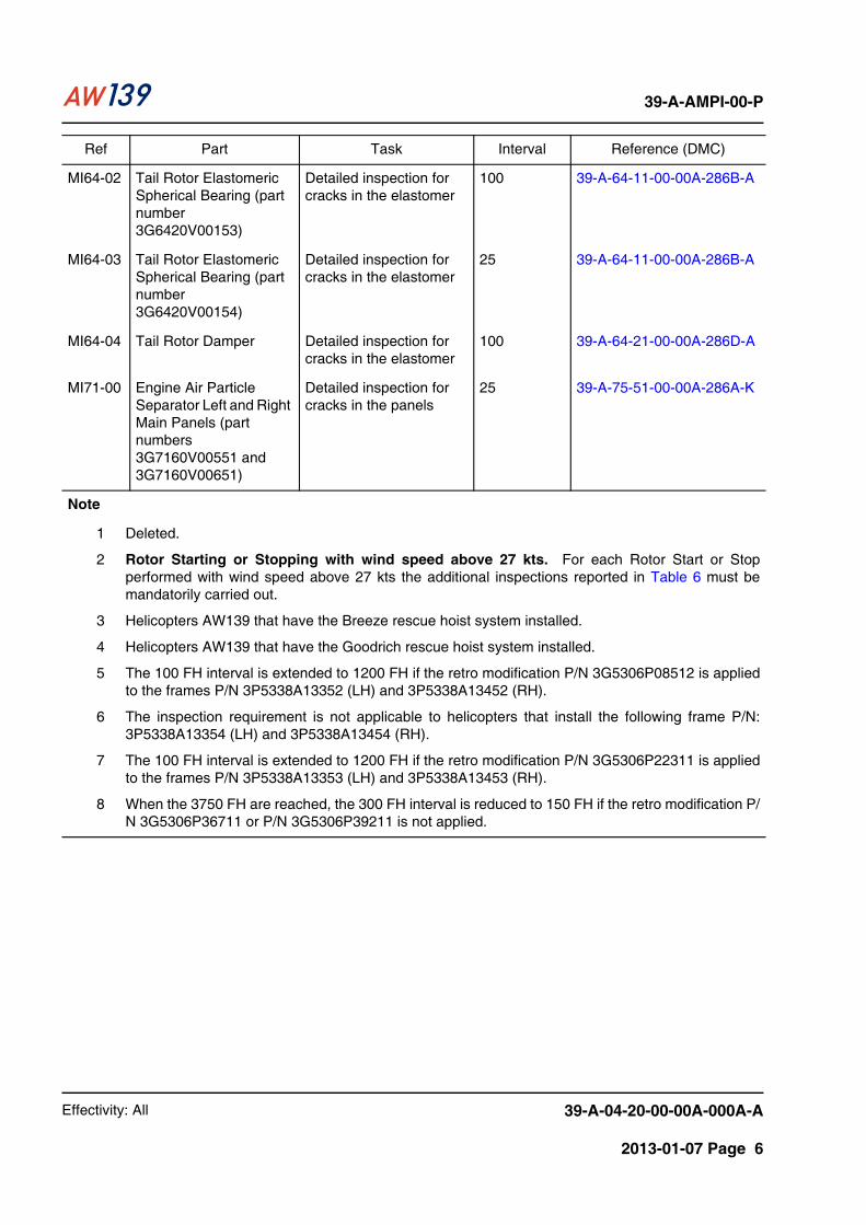
25 39-A-75-51-00-00A-286A-K
Note
1 Deleted.
2 Rotor Starting or Stopping with wind speed above 27 kts. For each Rotor Start or Stopperformed with wind speed above 27 kts the additional inspections reported in Table 6 must bemandatorily carried out.
3 Helicopters AW139 that have the Breeze rescue hoist system installed.
4 Helicopters AW139 that have the Goodrich rescue hoist system installed.
5 The 100 FH interval is extended to 1200 FH if the retro modification P/N 3G5306P08512 is appliedto the frames P/N 3P5338A13352 (LH) and 3P5338A13452 (RH).
6 The inspection requirement is not applicable to helicopters that install the following frame P/N:3P5338A13354 (LH) and 3P5338A13454 (RH).
7 The 100 FH interval is extended to 1200 FH if the retro modification P/N 3G5306P22311 is appliedto the frames P/N 3P5338A13353 (LH) and 3P5338A13453 (RH).
8 When the 3750 FH are reached, the 300 FH interval is reduced to 150 FH if the retro modification P/N 3G5306P36711 or P/N 3G5306P39211 is not applied.
Ref Part Task Interval Reference (DMC)

Effectivity: All 39-A-04-20-00-00A-000A-A
2013-01-07 Page 7
39-A-AMPI-00-P
Table 3 Mandatory inspections – Rescue hoist system (Breeze)
Table 4 Mandatory inspections – Double rescue hoist system (Goodrich)
Table 5 Mandatory inspections – Single rescue hoist system (Goodrich)
Table 6 Rotor Starting or Stopping with wind speed above 27 kts - Additional inspections
Ref Part Task Interval Reference (DMC)
MI25-02 Rescue hoist GVI of entire usable length of the cable for damage and condition
Prior the first use of the day
39-A-25-91-01-00A-285A-K
Ref Part Task Interval Reference (DMC)
MI25-03 Rescue hoist cable Do a GVI of the maximum length of cable used during the day operation for damage and condition
After the last flight of the day or before the first flight of the day if the rescue hoist is used or it is envisaged to be used
39-A-25-94-01-00A-285A-K
Ref Part Task Interval Reference (DMC)
MI25-04 Rescue hoist cable Do a GVI of the maximum length of cable used during the day operation for damage and condition
After the last flight of the day or before the first flight of the day if the rescue hoist is used or it is envisaged to be used
39-A-25-96-01-00A-285A-K
Ref Part Task Interval Reference (DMC)
MI62-01 Main Rotor Blade Assembly
General visual inspection for damage
Within 15 FH from the event
39-A-62-11-00-00A-285A-A
MI64-01 Tail Rotor Blade Assembly
General visual inspection for damage
Within 15 FH from the event
39-A-64-11-00-00A-285A-A

Effectivity: All 39-A-04-20-00-00A-000A-A
2013-01-07 Page 8
39-A-AMPI-00-P
End of data module
4 External hoist liftThe external hoist lift is defined as an unreeling and recovery of the cable with a load attached tothe hook, independent of the length of the cable that is deployed/recovered.
An unreeling/recovery of the cable with no load on the hook is not considered to be a lift.
Any operation where a load is applied for half the operation (i.e. unreeling or recovery) must beconsidered as one lift.

Effectivity: All 39-A-04-30-00-00A-000A-A
2013-01-07 Page 1
39-A-AMPI-00-P
39-A-04-30-00-00A-000A-ACertification maintenance requirements – General
Originat or:-PB-----E-MAIL AW - CHPT04/21-12-2012-
Table of contentsReferences ................................................................................................................................... 11 Certification maintenance requirements............................................................................. 32 Column terms definitions.................................................................................................... 32.1 Reference (Ref).................................................................................................................. 32.2 System ............................................................................................................................... 32.3 Task.................................................................................................................................... 32.4 Interval................................................................................................................................ 32.5 Reference (DMC) ............................................................................................................... 32.6 Initials ................................................................................................................................. 3
List of tables1 References ......................................................................................................................... 12 Certification maintenance requirements............................................................................. 43 Certification maintenance requirements - Rescue hoist system (Breeze).......................... 74 Certification maintenance requirements - Double rescue hoist system (Goodrich) ........... 85 Certification maintenance requirements - Single rescue hoist system (Goodrich)........... 10
References
Table 1 References
Data Module Title
39-A-34-23-00-00A-321A-A Attitude heading reference system – Operational check
39-A-23-10-00-00A-321A-A Speech communications - Backup function – Operational check
39-A-34-61-00-00A-321A-A Flight management system - MCDU backup function – Operational check
39-B-31-61-00-00A-321B-A Central display system - Display controllers – Operational check
39-A-24-61-00-00A-321A-A DC electrical load distribution system - Essential bus feed circuit breakers – Operational check
39-A-24-32-00-00A-321A-A Battery power generation system - Diode modules – Operational check
39-A-24-31-00-00A-321A-A DC main generation system - Generator control units – Operational check
39-B-24-21-00-00A-321B-A AC generation system - Number 2 AC generator control unit – Operational check
39-B-24-21-00-00A-321C-A AC generation system - Number 2 power distribution unit – Operational check
39-B-24-21-00-00A-365A-A AC generation system - Connections between generator control units and IPS/AGB status panel – Continuity check
39-A-25-92-00-00A-344A-K Cargo hook system - Relay K40 – Functional check

Effectivity: All 39-A-04-30-00-00A-000A-A
2013-01-07 Page 2
39-A-AMPI-00-P
39-A-26-10-00-00A-321A-A Detection - Sensing element pressure transducers – Operational check
39-A-30-60-00-00A-344B-K Full ice protection system - Ice detector control box functions – Functional check
39-A-30-64-00-00A-344B-K Ice detection system - Pressure switches and shut off valves – Functional check
39-A-30-71-00-00A-321A-K Ice detection system - Ice detector control boxes – Operational check
39-A-30-71-00-00A-344B-K Ice detection system - LIPS control box – Functional check
39-B-63-20-05-48A-286A-K Freewheel actuator - Freewheel inner race (main gearbox right input shaft module) – Detailed inspection
39-A-64-21-00-00A-286A-A Tail rotor head installation - Lag damper spherical bearings – Detailed inspection
39-A-67-10-00-00A-314A-A Main rotor control - Balance springs – Visual check
39-A-76-10-00-00A-321A-A Power controls - Overspeed limiters – Operational check
39-A-95-61-00-00A-321A-K Emergency flotation system – FLOAT switches - Operational check
39-A-25-91-00-00A-321A-K Rescue hoist system - Limit switches and cable foul assembly – Operational check
39-A-25-91-01-00A-321A-K Rescue hoist - Handwheel assembly bearing – Operational check
39-A-25-91-01-00A-285A-K Rescue hoist - Bumper assembly, cable cutter and cable – General visual inspection
39-A-04-20-00-00A-000A-A Mandatory inspections – General
39-A-25-94-00-00A-321A-K Double rescue hoist system - Limit switches – Operational check
39-A-25-94-00-00A-321B-K Double rescue hoist system - Cable cutter circuit and cable foul assembly – Operational check
39-A-25-94-01-00A-285A-K Double rescue hoist - Bumper assembly, cable cutter and cable – General visual inspection
39-A-25-94-00-00A-321C-K Double rescue hoist system - Deceleration and limit switches – Operational check
39-A-05-51-00-00A-000A-A Out of phase maintenance checks – General
39-A-25-96-00-00A-321A-K Single rescue hoist system - Limit switches and cable foul assembly – Operational check
39-A-25-96-00-00A-321B-K Single rescue hoist system - Cable cutter circuit – Operational check
Table 1 References
Data Module Title

Effectivity: All 39-A-04-30-00-00A-000A-A
2013-01-07 Page 3
39-A-AMPI-00-P
Description
1 Certification maintenance requirementsThe Table 2 thru Table 5 that follows gives the data about the mandatory maintenance checksthat were identified during the certification process.
Parts listed in the following schedule must be mandatorily inspected when the indicated intervalis reached.
2 Column terms definitions
2.1 Reference (Ref)This column gives the unique reference [CM (Certification Maintenance) plus the system numberfollowed by a progressive number] which identifies each listed task.
2.2 SystemThis column gives the technical name of the system.
2.3 TaskThis column gives the description of the work to do.
2.4 IntervalThis column gives the maintenance check interval for the component. Unless specified differently,the interval is in Flying Hours (FH). Flying hours are defined as those hours accumulated fromtake-off to landing.
Inspection intervals are mandatory and cannot be increased. Inspection intervals can beanticipated provided that the next inspections intervals do not exceed the values mandated in thischapter.
Example:
– Task interval: 100 FH. If task is performed at 85 FH, next task must be performed within 100FH from the previous compliance.
2.5 Reference (DMC)This column shows the Data Module Code which gives the instructions to do the check.
2.6 InitialsWhen you use a copy of the data module for maintenance record purposes, this column, gives thespace to write the initials of the person who did the check.
39-A-25-96-01-00A-285A-K Single rescue hoist - Bumper assembly, cable cutter and cable – General visual inspection
39-A-25-96-00-00A-321C-K Single rescue hoist system - Deceleration and limit switches – Operational check
Table 1 References
Data Module Title

Effectivity: All 39-A-04-30-00-00A-000A-A
2013-01-07 Page 4
39-A-AMPI-00-P
Table 2 Certification maintenance requirements
Ref System Task Interval Reference (DMC) Initials
CM22-01 Automatic Flight Control
OC of MAU AHRS input 1500 39-A-34-23-00-00A-321A-A
CM23-01 Communication OC of MCDU and audio panel backup functions (ICS backup relays will be checked when performing this task)
1200 39-A-23-10-00-00A-321A-A
39-A-34-61-00-00A-321A-A
CM23-02 Communication OC of CCDs selection switches
1200 39-B-31-61-00-00A-321B-A
CM24-01 Electrical Power OC of essential bus feed circuit breakers (CB3, CB4, CB47 and CB48)
600 39-A-24-61-00-00A-321A-A
CM24-02 Electrical Power OC of diode modules (CR3, CR23 and CR24)
1200 39-A-24-32-00-00A-321A-A
CM24-03 Electrical Power OC of GCU over-voltage protection function
300 39-A-24-31-00-00A-321A-A
CM24-04 AC Generation System (FIPS)
OC to verify the correct functionality of the number 2 Generator Control Unit (GCU)
300 39-B-24-21-00-00A-321B-A
CM24-05 AC Generation System (FIPS)
OC to verify the correct reconfiguration of the number 2 Power Distribution Panel (PDP) when number 2 Generator is failed
20000 39-B-24-21-00-00A-321C-A
CM24-06 Ice Protection System Cables Interfacing
OC to verify the electrical continuity between GCU’s and IPS-AGB Status Panel (Channel A and Channel B)
20000 39-B-24-21-00-00A-365A-A
CM25-09 Cargo Hook Functional check of relay K40 for dormant open circuit failures
2000 39-A-25-92-00-00A-344A-K
CM25-26 Deleted
CM26-01 Engine Fire Protection
OC of pressure transducer alarm switch contacts
3000 39-A-26-10-00-00A-321A-A
CM30-01 Ice Protection System (FIPS)
OC to verify the correct functionality of the Ice Detector Box 1 (IDB) functions
200 39-A-30-60-00-00A-344B-K
CM30-02 Ice Protection System (FIPS)
OC to verify the correct functionality of the number 1 pressure switch bleed lines
10000 39-A-30-64-00-00A-344B-K

Effectivity: All 39-A-04-30-00-00A-000A-A
2013-01-07 Page 5
39-A-AMPI-00-P
CM30-03 Ice Protection System (FIPS)
OC to verify the correct functionality of the number 1 shut-off valve bleed lines
10000 39-A-30-64-00-00A-344B-K
CM30-04 Ice Protection System (FIPS)
OC to verify the correct functionality of the Ice Detector Box 2 (IDB) functions
200 39-A-30-60-00-00A-344B-K
CM30-05 Ice Protection System (FIPS)
OC to verify the correct functionality of the number 2 pressure switch bleed lines
10000 39-A-30-64-00-00A-344B-K
CM30-06 Ice Protection System (FIPS)
OC to verify the correct functionality of the number 2 shut-off valve bleed lines
10000 39-A-30-64-00-00A-344B-K
CM30-07 Limited Ice Protection System (LIPS)
OC of the Ice Detector Box to verify the correct functionality of the IDB1 and IDB2 function
300 39-A-30-71-00-00A-321A-K
CM30-08 Limited Ice Protection System (LIPS)
FC of the Ice Control Box to verify the correct functionality of the ICB channels, the ability of each channel to communicate with the MAUs and to verify that no internal minor failures of the channel are present
3600 39-A-30-71-00-00A-344B-K
CM32-01 Landing gear control valve (Goodrich landing gear installation)
Do a FC to detect internal leaks
5000 Note 4
CM63-01 Right Input Freewheel Shaft (Main gearbox equipped with AGB system)
DI of the roller bearing inner race (most internal) for damage and condition (freewheel shaft and actuator removal required)
600 39-B-63-20-05-48A-286A-K
CM64-01 Tail Rotor and Rotating Controls
DI of tail rotor damper spherical bearings for condition, damage and play
25 39-A-64-21-00-00A-286A-A
If special tool is available, removal is not required. Axial play check only. Maximum play allowed: 0.1 mm (0.0039 in)
CM67-01 Fixed Flight Control
VC of pitch, roll and yaw anchor spring mechanisms
1200 / 2 years
39-A-67-10-00-00A-314A-A
Ref System Task Interval Reference (DMC) Initials

Effectivity: All 39-A-04-30-00-00A-000A-A
2013-01-07 Page 6
39-A-AMPI-00-P
CM67-02 Main Rotor and Tail Rotor Servoactuators
Check of redundant seal sets 3000 Note 2
CM71-01 Engine Installation
OC of the NF/NPT overspeed limiter in the auto engine control system
3500 39-A-76-10-00-00A-321A-A
CM71-02 Engine Power Available Trend Monitoring (3-Display Helicopter Only)
Perform and record on the suitable provided forms (see PT6C-67C Engine Maintenance Manual) the power assurance check trend of both the engines
100 Note 3
CM71-03 Engine Power Available Trend Monitoring (4-Display Helicopter Only)
Perform and record on the suitable provided forms (see PT6C-67C Engine Maintenance Manual) the power assurance check trend of both the engines
50 Note 3
CM95-01 Flotation System
OC of the guarded late arm switches located on the pilot and co-pilot collective grips for dormant closed circuit failures of the switch guard contacts and the push button contacts
800 39-A-95-61-00-00A-321A-K
Note
1 No tolerance above published intervals is allowed on Certification Maintenance Requirements.
2 Task to be performed by sending the components to the Manufacturer.
3 Task to be performed by following the instructions contained in the last issue of P&W PT6C-67CEngine Maintenance Manual.
4 At the specified limit the component will be replaced and the removed item will be sent to the VendorSupplier for schedule activities.
Ref System Task Interval Reference (DMC) Initials

Effectivity: All 39-A-04-30-00-00A-000A-A
2013-01-07 Page 7
39-A-AMPI-00-P
Table 3 Certification maintenance requirements - Rescue hoist system (Breeze)
Ref System Task Interval Reference (DMC) Initials
CM25-01 Rescue Hoist OC of the full-out and full-in limit switches of the hoist assembly for correct operation
Prior the first use of the day
39-A-25-91-00-00A-321A-K
CM25-02 Rescue Hoist OC of the intermediate speed limit switch of the hoist assembly for correct operation
Prior the first use of the day
39-A-25-91-00-00A-321A-K
CM25-03 Rescue Hoist OC of the handwheel assembly bearing of the hook assembly for freedom of rotation
Prior the first use of the day
39-A-25-91-01-00A-321A-K
CM25-04 Rescue Hoist GVI of the bumper assembly of the hook assembly for damage and condition
Daily 39-A-25-91-01-00A-285A-K
CM25-05 Rescue Hoist GVI of cable cutter of the hoist assembly to make sure that the cotter pin is correctly installed
Prior the first use of the day
39-A-25-91-01-00A-285A-K
CM25-06 Rescue Hoist OC of the cable foul assembly of the hoist assembly for correct operation
Prior the first use of the day
39-A-25-91-00-00A-321A-K
CM25-07 Transferred (Note 3)
CM25-08 Rescue Hoist After use in a salt water environment, clean the cable and the hook assembly with fresh water, then dry with a lint free cloth
After the last use of the day
Note 2
Note
1 No tolerance above published intervals is allowed on Certification Maintenance Requirements.
2 Task to be performed by an Operator qualified by the Equipment Manufacturer, following theinstructions contained in the last issue of the relevant Component Maintenance Manual.
3 Task transferred to AMPI CHAPTER 04 AIRWORTHINESS LIMITATIONS - Mandatory inspections- General (39-A-04-20-00-00A-000A-A).

Effectivity: All 39-A-04-30-00-00A-000A-A
2013-01-07 Page 8
39-A-AMPI-00-P
Table 4 Certification maintenance requirements - Double rescue hoist system (Goodrich)
Ref System Task Interval Reference (DMC) Initials
CM25-10 Rescue Hoist (part number 3G2591V01531)
OC of the rescue hoist assembly full-out limit and full-stop limit switch function to ensure correct operation
20 39-A-25-94-00-00A-321A-K
Rescue Hoist (part number 3G2591V01532)
OC of the rescue hoist assembly full-out limit and full-stop limit switch function to ensure correct operation
450 39-A-25-94-00-00A-321A-K
CM25-11 Rescue Hoist (part number 3G2591V01531)
OC of the rescue hoist assembly cable foul detection circuit to ensure hoisting operations stop and indications are generated
20 39-A-25-94-00-00A-321B-K
Rescue Hoist (part number 3G2591V01532)
OC of the rescue hoist assembly cable foul detection circuit to ensure hoisting operations stop and indications are generated
450 39-A-25-94-00-00A-321B-K
CM25-12 Transferred (Note 2)
CM25-13 Transferred (Note 2)
CM25-14 Rescue Hoist (part number 3G2591V01531)
GVI of the full cable length for damage and condition
20 39-A-25-94-01-00A-285A-K
Rescue Hoist (part number 3G2591V01532)
GVI of the full cable length for damage and condition
450 39-A-25-94-01-00A-285A-K
CM25-15 Transferred (Note 2)

Effectivity: All 39-A-04-30-00-00A-000A-A
2013-01-07 Page 9
39-A-AMPI-00-P
CM25-16 Rescue Hoist OC of the rescue hoist assembly deceleration switches S7 and S8 and caution limit switches S5 and S6 for dormant closed circuit failure of either one of the switches in series
5000 or rescue hoist assembly overhaul (Note 3)
39-A-25-94-00-00A-321C-K
CM25-17 Rescue Hoist OC of the rescue hoist assembly full-out limit switches S3 and S4 and full-stop limit switches S1 and S2 for dormant closed circuit failure of either one of the switches in series
5000 or rescue hoist assembly overhaul (Note 3)
39-A-25-94-00-00A-321C-K
Note
1 No tolerance above published intervals is allowed on Certification Maintenance Requirements.
2 Task transferred to AMPI Chapter 05 - Out of phase maintenance checks - General (39-A-05-51-00-00A-000A-A).
3 Use the limit that occurs first.
Ref System Task Interval Reference (DMC) Initials

Effectivity: All 39-A-04-30-00-00A-000A-A
2013-01-07 Page 10
39-A-AMPI-00-P
Table 5 Certification maintenance requirements - Single rescue hoist system (Goodrich)
Ref System Task Interval Reference (DMC) Initials
CM25-18 Rescue Hoist (part number 3G2591V01531)
OC of the rescue hoist assembly full-out limit and full-stop limit switch function to ensure correct operation
20 39-A-25-96-00-00A-321A-K
Rescue Hoist (part number 3G2591V01532)
OC of the rescue hoist assembly full-out limit and full-stop limit switch function to ensure correct operation
450 39-A-25-96-00-00A-321A-K
CM25-19 Rescue Hoist (part number 3G2591V01531)
OC of the rescue hoist assembly cable foul detection circuit to ensure hoisting operations stop and indications are generated
20 39-A-25-96-00-00A-321B-K
Rescue Hoist (part number 3G2591V01532)
OC of the rescue hoist assembly cable foul detection circuit to ensure hoisting operations stop and indications are generated
450 39-A-25-96-00-00A-321B-K
CM25-20 Transferred (Note 2)
CM25-21 Transferred (Note 2)
CM25-22 Rescue Hoist (part number 3G2591V01531)
GVI of the full cable length for damage and condition
20 39-A-25-96-01-00A-285A-K
Rescue Hoist (part number 3G2591V01532)
GVI of the full cable length for damage and condition
450 39-A-25-96-01-00A-285A-K
CM25-23 Transferred (Note 2)

Effectivity: All 39-A-04-30-00-00A-000A-A
2013-01-07 Page 11
39-A-AMPI-00-P
End of data module
CM25-24 Rescue Hoist OC of the rescue hoist assembly deceleration switches S7 and S8 and caution limit switches S5 and S6 for dormant closed circuit failure of either one of the switches in series
5000 or rescue hoist assembly overhaul (Note 3)
39-A-25-96-00-00A-321C-K
CM25-25 Rescue Hoist OC of the rescue hoist assembly full-out limit switches S3 and S4 and full-stop limit switches S1 and S2 for dormant closed circuit failure of either one of the switches in series
5000 or rescue hoist assembly overhaul (Note 3)
39-A-25-96-00-00A-321C-K
Note
1 No tolerance above published intervals is allowed on Certification Maintenance Requirements.
2 Task transferred to AMPI Chapter 05 - Out of phase maintenance checks - General (39-A-05-51-00-00A-000A-A).
3 Use the limit that occurs first.
Ref System Task Interval Reference (DMC) Initials

Effectivity: All 39-A-04-30-00-00A-000A-A
2013-01-07 Page 12
39-A-AMPI-00-P
THIS PAGE INTENTIONALLY LEFT BLANK