136681563 ABB Handbook Generator Protection 757292 ENa
37
Distribution Automation Handbook Section 8.12 Generator Protection
-
Upload
suresh-k-krishnasamy -
Category
Documents
-
view
256 -
download
4
Transcript of 136681563 ABB Handbook Generator Protection 757292 ENa

7/27/2019 136681563 ABB Handbook Generator Protection 757292 ENa
http://slidepdf.com/reader/full/136681563-abb-handbook-generator-protection-757292-ena 1/36
Distribution Automation HandbookSection 8.12 Generator Protection
7/27/2019 136681563 ABB Handbook Generator Protection 757292 ENa
http://slidepdf.com/reader/full/136681563-abb-handbook-generator-protection-757292-ena 2/36
Distribution Automation Handbook (prototype)
Power System Protection, 8.12 Generator Protection
1MRS757292
2
Contents
8.12 Protection of Synchronous Generators .......................................................................................... 4
8.12.1 Introduction .............................................................................................................................. 4 8.12.1.1 GENERAL DEMANDS ............................................................................................................................................................ 4
8.12.2 Synchronous Machines ............................................................................................................. 4 8.12.2.1 POWER STATION CONFIGURATION ........................................................................................................................................ 4
8.12.3 Earthing of Generators ............................................................................................................. 4
8.12.4 Faults and Abnormalities ......................................................................................................... 5 8.12.4.1 STATOR FAULTS................................................................................................................................................................... 5
8.12.4.2 R OTOR FAULTS .................................................................................................................................................................... 5 8.12.4.3 ABNORMAL OPERATING CONDITIONS ................................................................................................................................... 6 8.12.5 Differential Protection .............................................................................................................. 6
8.12.6 Underimpedance Protection ..................................................................................................... 6
8.12.7 Overcurrent Protection ............................................................................................................. 6
8.12.8 Stator Earth-fault Protection .................................................................................................... 7 8.12.8.1 EARTHING OF GENERATING U NITS ....................................................................................................................................... 7 8.12.8.2 THE EARTH-FAULT PROTECTION SYSTEM ............................................................................................................................. 8 8.12.8.3 LINE E ND EARTH-FAULT PROTECTION.................................................................................................................................. 9
8.12.8.3.1 Unit Generator-Transformer Configuration ..................................... ....................... ....................... ..................... ... 9 8.12.8.3.2 Several Generators Connected to a Common Busbar ...................... ....................... ....................... ....................... 11
8.12.8.4 NEUTRAL-END EARTH-FAULT PROTECTION ........................................................................................................................ 12 8.12.9 Field Earth-fault Protection ................................................................................................... 15
8.12.9.1 OPEN CIRCUITS.................................................................................................................................................................. 15 8.12.9.2 EARTH FAULTS .................................................................................................................................................................. 15 8.12.9.3 SHORT CIRCUITS................................................................................................................................................................ 15 8.12.9.4 EARTH-FAULT DETECTORS FOR U NITS WITH BRUSHES........................................................................................................ 16 8.12.9.5 EARTH-FAULT DETECTORS FOR U NITS WITHOUT BRUSHES ................................................................................................. 16
8.12.10 Underexcitation Protection ................................................................................................ 17 8.12.10.1 U NDEREXCITATION OF SYNCHRONOUS MACHINES ....................................................................................................... 17 8.12.10.2 LOSS OF EXCITATION ................................................................................................................................................... 17 8.12.10.3 U NDEREXCITATION PROTECTION.................................................................................................................................. 17
8.12.11 Overvoltage Protection ...................................................................................................... 18
8.12.12 Reverse Power Protection .................................................................................................. 18
8.12.13 Unbalance Protection ........................................................................................................ 20 8.12.13.1 U NBALANCED LOADING............................................................................................................................................... 20
8.12.13.1.1 Causes of Unbalanced Loading ..................... ....................... ....................... ....................... ....................... ........... 20 8.12.13.1.2 Consequences for the Generators ....................... ....................... ....................... ....................... ...................... ....... 21 8.12.13.1.3 Turbo-Generators ................................................................................................................................................. 21 8.12.13.1.4 Hydro-Generators ................................................................................................................................................. 21
8.12.13.2 CONTINUOUS I2-CAPABILITY ........................................................................................................................................ 22 8.12.13.3 TEMPORARY I2-CAPABILITY ......................................................................................................................................... 23 8.12.13.4 U NBALANCE PROTECTION ............................................................................................................................................ 25
8.12.14 Out-of-Step Protection ....................................................................................................... 25 8.12.14.1 ASYNCHRONOUS OPERATION ....................................................................................................................................... 25
8.12.15 Abnormal Frequency Protection ........................................................................................ 26 8.12.15.1 AIMS OF THE ABNORMAL FREQUENCY PROTECTION ..................................................................................................... 27 8.12.15.2 EFFECTS OF ABNORMAL FREQUENCY ........................................................................................................................... 27 8.12.15.3 COORDINATION WITH LOAD SHEDDING ........................................................................................................................ 27
8.12.15.4 R EALIZATION OF ABNORMAL FREQUENCY PROTECTION ............................................................................................... 28

7/27/2019 136681563 ABB Handbook Generator Protection 757292 ENa
http://slidepdf.com/reader/full/136681563-abb-handbook-generator-protection-757292-ena 3/36
Distribution Automation Handbook (prototype)
Power System Protection, 8.12 Generator Protection
1MRS757292
3
8.12.16 Inadvertent Energizing Protection ..................................................................................... 28
8.12.16.1 I NADVERTENT E NERGIZING.......................................................................................................................................... 28 8.12.16.2 GENERATOR R ESPONSE TO I NADVERTENT E NERGIZING ................................................................................................ 28 8.12.16.3 DAMAGE CAUSED BY I NADVERTENT E NERGIZING ........................................................................................................ 29 8.12.16.4 SYSTEMS TO DETECT I NADVERTENT E NERGIZING......................................................................................................... 29 8.12.16.5 SCHEMES TO DETECT BREAKER HEAD FLASHOVER ...................................................................................................... 29
8.12.17 Breaker Failure Protection ................................................................................................ 30
7/27/2019 136681563 ABB Handbook Generator Protection 757292 ENa
http://slidepdf.com/reader/full/136681563-abb-handbook-generator-protection-757292-ena 4/36
Distribution Automation Handbook (prototype)
Power System Protection, 8.12 Generator Protection
1MRS757292
4
8.12 Protection of Synchronous Generators
Most power systems tolerate the disconnection of one generating unit, one power transformer, one power
line or one busbar section without running into serious problems. A fault on adjacent power system compo-
nent may cause the generator protection system to operate non-selectively.
8.12.1 Introduction
A generator has more failure modes than any other component in the power system. It is very important
that the protection system detect all faults that may hurt humans and damage equipment. The generator
protection system must detect the faults rapidly.
8.12.1.1 General Demands
The general demands on the protection system are based on some risk analysis, experience and tradition.
Commonly, it is required that earth faults, short circuits and other severe faults must be detected by two
independent protections. The fault must be cleared even if one switching device fails to operate. The
generator protection system must also provide adequate backup protection for adjacent components.
8.12.2 Synchronous Machines
A synchronous machine is not a simple device. The armature, or stator, winding is arranged in three sym-
metrical phase belts in slots in the stator surface. The magnetic field intensity can be controlled via the DC-current in the rotor, or field, winding. A synchronous machine can operate as a generator or as a motor.
8.12.2.1 Power Station Con figu ration
Varying power station configurations obstruct the use of a uniform and standardized generator protection
system. The most important factor is the varying power station configuration. Besides the varying power
station configuration, following factors influence the design of the generator protection system:
• generator circuit-breaker or not
• earthing of the generator neutral
• location of the voltage transformers
• location of the current transformers
8.12.3 Earthing of Generators
There are even more methods for earthing of generators than for earthing of networks. In power stations,
there are many combinations of generators, transformers, busbars and outgoing power lines. References
[8.12.11] and [8.12.14] provide information on the earthing of generators. Even if there are many
possibilities, the main focus here is on the resistance earthing, which is the dominating system. A neutral
point resistor controls the potential of the generator windings. The introduction of a neutral-point resistor

7/27/2019 136681563 ABB Handbook Generator Protection 757292 ENa
http://slidepdf.com/reader/full/136681563-abb-handbook-generator-protection-757292-ena 5/36
Distribution Automation Handbook (prototype)
Power System Protection, 8.12 Generator Protection
1MRS757292
5
will result in a small earth-fault current. We can neglect the risk for severe generator damages if the earth-
fault current is less than 15 A.
The neutral-point resistor can also be connected on the secondary side of a distribution transformer. The
rated voltage of the neutral-point transformer must not be less than the rated phase-to-neutral voltage of the
generator. To reduce the inrush current to the neutral-point transformer, it should have a rated voltage equal
to the rated phase-to-phase voltage of the generator.
8.12.4 Faults and Abnormalities
The protection of synchronous generators involves the consideration of more possible faults and abnormal
conditions than the protection of any other power system component. We have to consider (1) stator faults,
(2) rotor faults, (3) abnormal operating conditions and (4) faults in the connected power grid.
8.12.4.1 Stato r Fault s
Damage to the stator winding itself or to its insulation may cause stator short circuits or stator earth faults.
Ageing, overvoltage, overcurrent or loss of cooling may cause stator short circuits. External short circuits,
improper synchronization and loss of synchronism may cause large currents. These currents cause high
forces that may displace the stator winding and cause an internal short circuit.
An external short circuit is accompanied by very large fault currents. The electromechanical forces increase
considerably when the size of the generator increases. The size of the electromechanical forces may amount
to more than 100 N/cm at sudden short circuits. Generally, the utilities require that synchronous generators
shall withstand, without damage, all types of short circuit on the generator terminals.
Short circuits clear of earth are less common faults. They may occur on the end portion of the stator coils.
They may also occur in the slots if there are two coils in the same slot. In the latter case, the fault will
involve earth in a very short time.
Thermal power units commissioned during the last 30 years often have phase-segregated generator bus-
work. This reduces considerably the risk for two- and three-phase short circuits close to the generator
terminals.
Pohl has investigated how the earth-fault current damages the sheets of a synchronous machine. In [8.12.6],he describes the result of tests with three different insulating materials between the stator sheets, two
different values of the earth-fault current and four values of the fault clearance times.
8.12.4.2 Ro tor Fault s
The field circuit of a synchronous generator consists of the rotor winding proper and associated circuits.
These may include the slip rings and brushes, the field circuit-breaker, the armature of a rotating exciter or
the rectifier and the secondary winding of the magnetization transformer in a static exciter. This circuit is
an isolated DC-circuit and it is not necessary to earth it. The field circuit of modern generators is often
7/27/2019 136681563 ABB Handbook Generator Protection 757292 ENa
http://slidepdf.com/reader/full/136681563-abb-handbook-generator-protection-757292-ena 6/36
Distribution Automation Handbook (prototype)
Power System Protection, 8.12 Generator Protection
1MRS757292
6
operated unearthed. Earth faults, interturn faults and open circuits may occur in the field circuit. Over-
excitation or unbalanced loading may overheat the rotor.
8.12.4.3 Ab norm al Operat ing Cond it ions
Here are several situations when abnormal operating conditions can result in damages of the generating
unit. Some of the generator protection functions shall detect such abnormal conditions and initiate trip of
the generator before internal faults occur. Examples of abnormal conditions are: (1) abnormal voltage, (2)
abnormal frequency, (3) loss of synchronism and (4) unbalanced loading.
8.12.5 Differential Protection
A rotating machine provides a classical application of differential protection. The generator differential protection gives a fast and absolutely selective detection of generator stator short circuits. Usually, all
equipment, the CTs and the circuit-breakers are near each other. This minimizes the possible error due to
long cable runs. In addition, there is only one voltage level involved. This means that the CT ratio and
types can be the same.
It is very important that the differential protection does not operate in case of external short circuits. There
is a risk that the generator differential protection misoperates if a CT saturates. Close to power stations, the
time constant of the DC-component of the short circuit current may be very long and in the order of 100 to
150 ms. External short circuits with a fully developed DC-component puts severe demands on CT and
differential protection.
There may be more than one differential protection in a power station. In such cases, one differential
protection is associated with the generator and one with the generator step-up transformer. The sensitivity
of the generator step-up transformer differential may be about 20% of the rated current of the transformer.
This differential protection must not trip when the step-up transformer is energized and a high inrush
current flows from the network to the transformer. The overall differential protection provides backup
protection. The sensitivity of the overall differential protection is equal to the sensitivity of the transformer
differential protection. The overall differential protection may operate non-selectively if its tripping signal
is not delayed.
8.12.6 Underimpedance Protection
The line protections shall detect all shunt faults on the transmission network and trip the associated line
circuit-breakers. The backup protection system must operate when a line protection fails to operate or when
a circuit-breaker fails to interrupt the fault current. Often the generator underimpedance protection is one
part of this backup protection system. Sometimes there is no overall differential protection and another type
of backup protection is needed when the main protection fails to operate.
8.12.7 Overcurrent Protection
Many synchronous generators have rotating exciters. The old generators often have simple overcurrent
protections. The task of this overcurrent protection is to provide backup protection for internal short

7/27/2019 136681563 ABB Handbook Generator Protection 757292 ENa
http://slidepdf.com/reader/full/136681563-abb-handbook-generator-protection-757292-ena 7/36
Distribution Automation Handbook (prototype)
Power System Protection, 8.12 Generator Protection
1MRS757292
7
circuits and external shunt faults. Generally, the setting is n I ×5.1 where n I is the rated current of the
generator. The time delay is set to assure selectivity to other protections.
The introduction of static exciters made it necessary to replace the overcurrent protections by under-
impedance protections or voltage-restrained overcurrent protection.
Persisting overcurrent in the interval [ n I ×0.1 , n I ×4.1 ], where n I is the rated current of the generator, are
not detected by overcurrent protections or by underimpedance protections. Such overload must be detected
by dedicated thermal overload protections or by overtemperature sensors. Modern overload protections
may have an adjustable time constant that can be adjusted to the thermal properties of the generator.
8.12.8 Stator Earth-fault ProtectionThere are many methods for the detection of earth faults in generators. The choice of method depends on
the layout of the power plant. There are units with the generator and the step-up transformer connected as a
unit. The generator may or may not have a generator circuit-breaker. Two or more generators may share a
common step-up transformer. One may connect several generators to a common generator busbar. In such
cases, the number of step-up transformers may be one or more. The method for the detection of earth faults
depends also on the system earthing.
8.12.8.1 Earthin g of Generating Units
Most generators have high-impedance (high-resistance) earthed neutral. One method is to use a high-
voltage resistor and connect it directly to the neutral point of the generator. It is also possible to use a low-
voltage resistor and connect it on the secondary side of a single-phase distribution transformer. The neutral
point of the generator is connected to the primary side of the distribution transformer. The main task of the
neutral-point resistor is to limit the overvoltage on the windings and buswork of the generating units.
Overvoltages on the high-voltage side of the step-up transformer may cause such an overvoltage. The stray
capacitances between the high-voltage winding and the low-voltage winding of the step-up transformer
determine the magnitude of the overvoltage on the generator winding and associated buswork. It is often
necessary to install surge capacitors on the low-voltage side of the step-up transformer if there is a
generator breaker. The highest overvoltage on the buswork occurs when the generator breaker is open.
There is a rule of thumb for the selection of the neutral-point equipment. The effective resistance N
R [Ω]
seen from the neutral point of the generator should be equal to the capacitance to earth as in equation
(8.12.1). All capacitances are zero-sequence capacitances (capacitances to earth with all phase conductors
connected to each other).
)C +C +C +C ( 3
1 = R
t abw
N ⋅⋅ω
(8.12.1)
Here
wC Is the capacitance of the generator winding [F/phase]
7/27/2019 136681563 ABB Handbook Generator Protection 757292 ENa
http://slidepdf.com/reader/full/136681563-abb-handbook-generator-protection-757292-ena 8/36
Distribution Automation Handbook (prototype)
Power System Protection, 8.12 Generator Protection
1MRS757292
8
bC Is the capacitance of the buswork [F/phase]
t C Is the capacitance of the step-up transformer [F/phase]
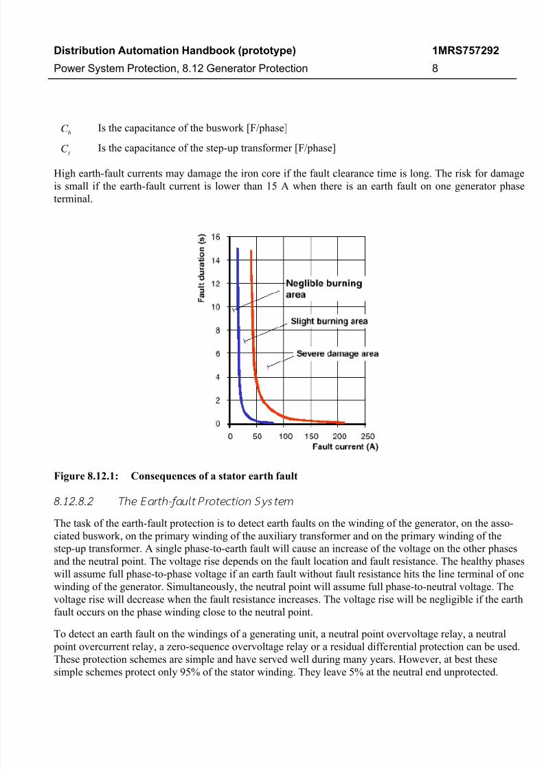
High earth-fault currents may damage the iron core if the fault clearance time is long. The risk for damage
is small if the earth-fault current is lower than 15 A when there is an earth fault on one generator phase
terminal.
Figure 8.12.1: Consequences of a stator earth fault
8.12.8.2 The Earth-fault Protectio n System
The task of the earth-fault protection is to detect earth faults on the winding of the generator, on the asso-
ciated buswork, on the primary winding of the auxiliary transformer and on the primary winding of thestep-up transformer. A single phase-to-earth fault will cause an increase of the voltage on the other phases
and the neutral point. The voltage rise depends on the fault location and fault resistance. The healthy phases
will assume full phase-to-phase voltage if an earth fault without fault resistance hits the line terminal of one
winding of the generator. Simultaneously, the neutral point will assume full phase-to-neutral voltage. The
voltage rise will decrease when the fault resistance increases. The voltage rise will be negligible if the earth
fault occurs on the phase winding close to the neutral point.
To detect an earth fault on the windings of a generating unit, a neutral point overvoltage relay, a neutral
point overcurrent relay, a zero-sequence overvoltage relay or a residual differential protection can be used.
These protection schemes are simple and have served well during many years. However, at best these
simple schemes protect only 95% of the stator winding. They leave 5% at the neutral end unprotected.

7/27/2019 136681563 ABB Handbook Generator Protection 757292 ENa
http://slidepdf.com/reader/full/136681563-abb-handbook-generator-protection-757292-ena 9/36
Distribution Automation Handbook (prototype)
Power System Protection, 8.12 Generator Protection
1MRS757292
9
Under unfavorable conditions, the blind zone may extend to 20% from the neutral. There are several
methods to detect an earth fault close to the neutral point. Figure 8.12.2 illustrates some fundamental properties of some types of earth-fault protections. The intention is to illustrate general methods and define
some classes of earth-fault protections.
TYPES OF EARTH FAULT PROTECTIONS
NA
B
C
Line End EarthFault Protection
Neutral End EarthFault Protection
Combined EarthFault Protection
Total Earth
Fault Protection
Figure 8.12.2: Types of earth-fault protections
The line end earth-fault protection can detect earth faults on almost entire winding but has unfortunately a blind zone close to the neutral point. The size of the blind zone may be 5-20%. The main task of the neutral
end earth-fault protection is to detect an earth fault close to the neutral point. Such protections may cover
20-40% of the winding.
8.12.8.3 Lin e End Earth-fault Protect ion
Neutral-point overvoltage protections, neutral-point overcurrent protections, zero-sequence overvoltage
protection and residual differential protections are line end earth-fault protections.
8.12.8.3.1 Unit Generator-Transformer Configuration
The neutral point overvoltage protection is a common earth-fault protection for unit-connected generators.
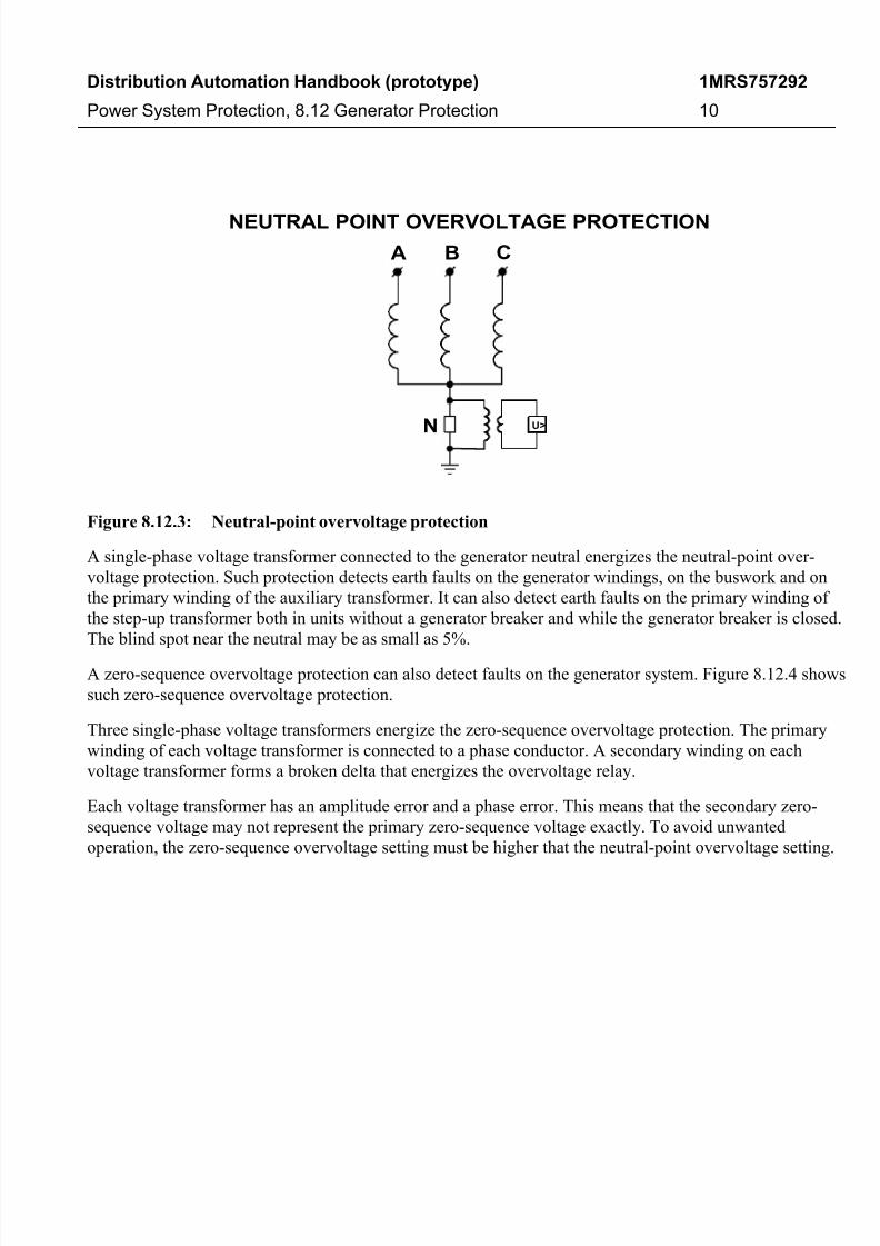
Figure 8.12.3 shows such a protection.
7/27/2019 136681563 ABB Handbook Generator Protection 757292 ENa
http://slidepdf.com/reader/full/136681563-abb-handbook-generator-protection-757292-ena 10/36
Distribution Automation Handbook (prototype)
Power System Protection, 8.12 Generator Protection
1MRS757292
10
NEUTRAL POINT OVERVOLTAGE PROTECTION
A B C
N U>
Figure 8.12.3: Neutral-point overvoltage protection
A single-phase voltage transformer connected to the generator neutral energizes the neutral-point over-
voltage protection. Such protection detects earth faults on the generator windings, on the buswork and on
the primary winding of the auxiliary transformer. It can also detect earth faults on the primary winding of
the step-up transformer both in units without a generator breaker and while the generator breaker is closed.
The blind spot near the neutral may be as small as 5%.
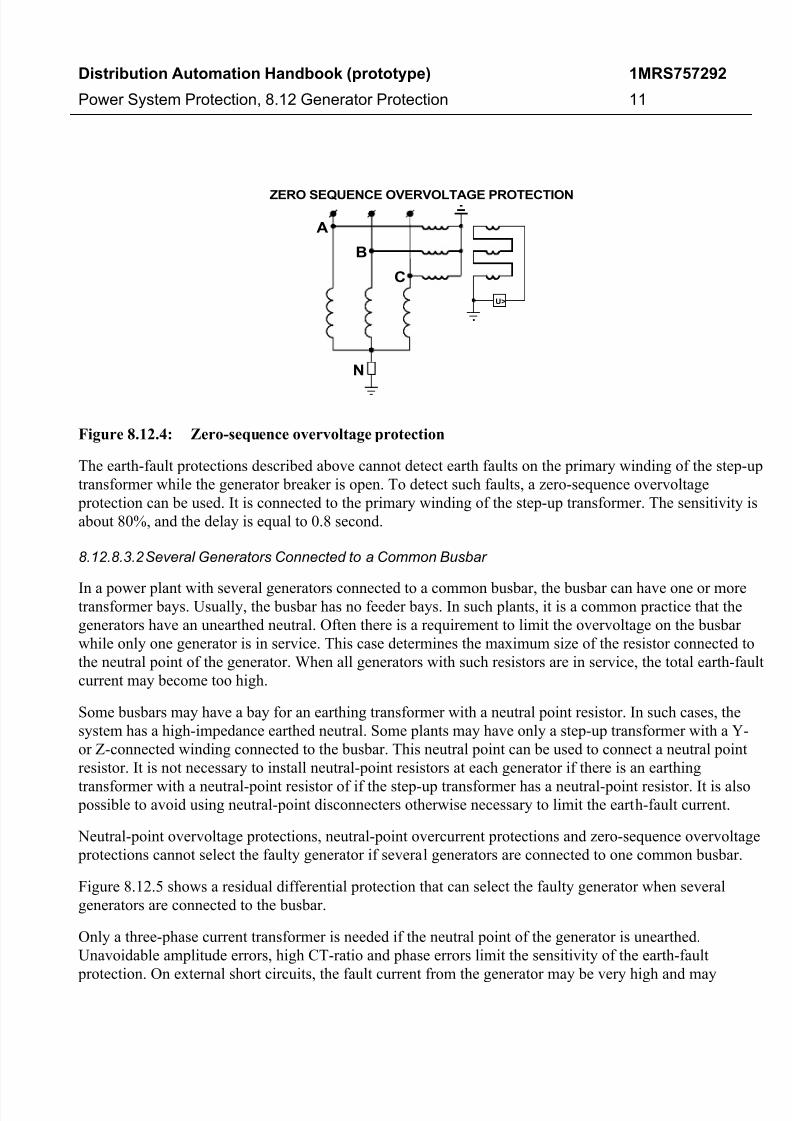
A zero-sequence overvoltage protection can also detect faults on the generator system. Figure 8.12.4 shows
such zero-sequence overvoltage protection.
Three single-phase voltage transformers energize the zero-sequence overvoltage protection. The primary
winding of each voltage transformer is connected to a phase conductor. A secondary winding on each
voltage transformer forms a broken delta that energizes the overvoltage relay.
Each voltage transformer has an amplitude error and a phase error. This means that the secondary zero-
sequence voltage may not represent the primary zero-sequence voltage exactly. To avoid unwanted
operation, the zero-sequence overvoltage setting must be higher that the neutral-point overvoltage setting.
7/27/2019 136681563 ABB Handbook Generator Protection 757292 ENa
http://slidepdf.com/reader/full/136681563-abb-handbook-generator-protection-757292-ena 11/36
Distribution Automation Handbook (prototype)
Power System Protection, 8.12 Generator Protection
1MRS757292
11
ZERO SEQUENCE OVERVOLTAGE PROTECTION
A
B
C
N
U>
Figure 8.12.4: Zero-sequence overvoltage protection
The earth-fault protections described above cannot detect earth faults on the primary winding of the step-up
transformer while the generator breaker is open. To detect such faults, a zero-sequence overvoltage
protection can be used. It is connected to the primary winding of the step-up transformer. The sensitivity is
about 80%, and the delay is equal to 0.8 second.
8.12.8.3.2 Several Generators Connected to a Common Busbar
In a power plant with several generators connected to a common busbar, the busbar can have one or moretransformer bays. Usually, the busbar has no feeder bays. In such plants, it is a common practice that the
generators have an unearthed neutral. Often there is a requirement to limit the overvoltage on the busbar
while only one generator is in service. This case determines the maximum size of the resistor connected to
the neutral point of the generator. When all generators with such resistors are in service, the total earth-fault
current may become too high.
Some busbars may have a bay for an earthing transformer with a neutral point resistor. In such cases, the
system has a high-impedance earthed neutral. Some plants may have only a step-up transformer with a Y-
or Z-connected winding connected to the busbar. This neutral point can be used to connect a neutral point
resistor. It is not necessary to install neutral-point resistors at each generator if there is an earthing
transformer with a neutral-point resistor of if the step-up transformer has a neutral-point resistor. It is also possible to avoid using neutral-point disconnecters otherwise necessary to limit the earth-fault current.
Neutral-point overvoltage protections, neutral-point overcurrent protections and zero-sequence overvoltage
protections cannot select the faulty generator if several generators are connected to one common busbar.
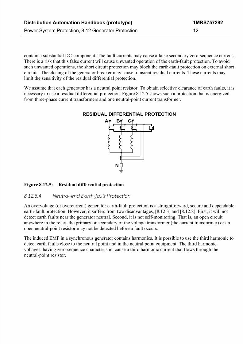
Figure 8.12.5 shows a residual differential protection that can select the faulty generator when several
generators are connected to the busbar.
Only a three-phase current transformer is needed if the neutral point of the generator is unearthed.
Unavoidable amplitude errors, high CT-ratio and phase errors limit the sensitivity of the earth-fault
protection. On external short circuits, the fault current from the generator may be very high and may
7/27/2019 136681563 ABB Handbook Generator Protection 757292 ENa
http://slidepdf.com/reader/full/136681563-abb-handbook-generator-protection-757292-ena 12/36
Distribution Automation Handbook (prototype)
Power System Protection, 8.12 Generator Protection
1MRS757292
12
contain a substantial DC-component. The fault currents may cause a false secondary zero-sequence current.
There is a risk that this false current will cause unwanted operation of the earth-fault protection. To avoidsuch unwanted operations, the short circuit protection may block the earth-fault protection on external short
circuits. The closing of the generator breaker may cause transient residual currents. These currents may
limit the sensitivity of the residual differential protection.
We assume that each generator has a neutral point resistor. To obtain selective clearance of earth faults, it is
necessary to use a residual differential protection. Figure 8.12.5 shows such a protection that is energized
from three-phase current transformers and one neutral-point current transformer.
RESIDUAL DIFFERENTIAL PROTECTION
A B C
N
R
Figure 8.12.5: Residual differential protection
8.12.8.4 Neutral-end Earth-fault Protect ion
An overvoltage (or overcurrent) generator earth-fault protection is a straightforward, secure and dependable
earth-fault protection. However, it suffers from two disadvantages, [8.12.3] and [8.12.8]. First, it will not
detect earth faults near the generator neutral. Second, it is not self-monitoring. That is, an open circuit
anywhere in the relay, the primary or secondary of the voltage transformer (the current transformer) or an
open neutral-point resistor may not be detected before a fault occurs.
The induced EMF in a synchronous generator contains harmonics. It is possible to use the third harmonic to
detect earth faults close to the neutral point and in the neutral point equipment. The third harmonic
voltages, having zero-sequence characteristic, cause a third harmonic current that flows through the
neutral-point resistor.
7/27/2019 136681563 ABB Handbook Generator Protection 757292 ENa
http://slidepdf.com/reader/full/136681563-abb-handbook-generator-protection-757292-ena 13/36
Distribution Automation Handbook (prototype)
Power System Protection, 8.12 Generator Protection
1MRS757292
13
Phase-to-Neutral Voltage Phase A
-15-10
-505
1015
0.00 0.02 0.04 0.06 0.08 0.10
Time [s]
V o l t a g e [ k V ]
Phase-to-Neutral Voltage Phase B
-15-10
-505
1015
0.00 0.02 0.04 0.06 0.08 0.10
Time [s]
V o l t a g e [ k V ]
Phase-to-Neutral Voltage Phase C
-15-10
-505
1015
0.00 0.02 0.04 0.06 0.08 0.10
Time [s]
V o l t a g e [ k V ]
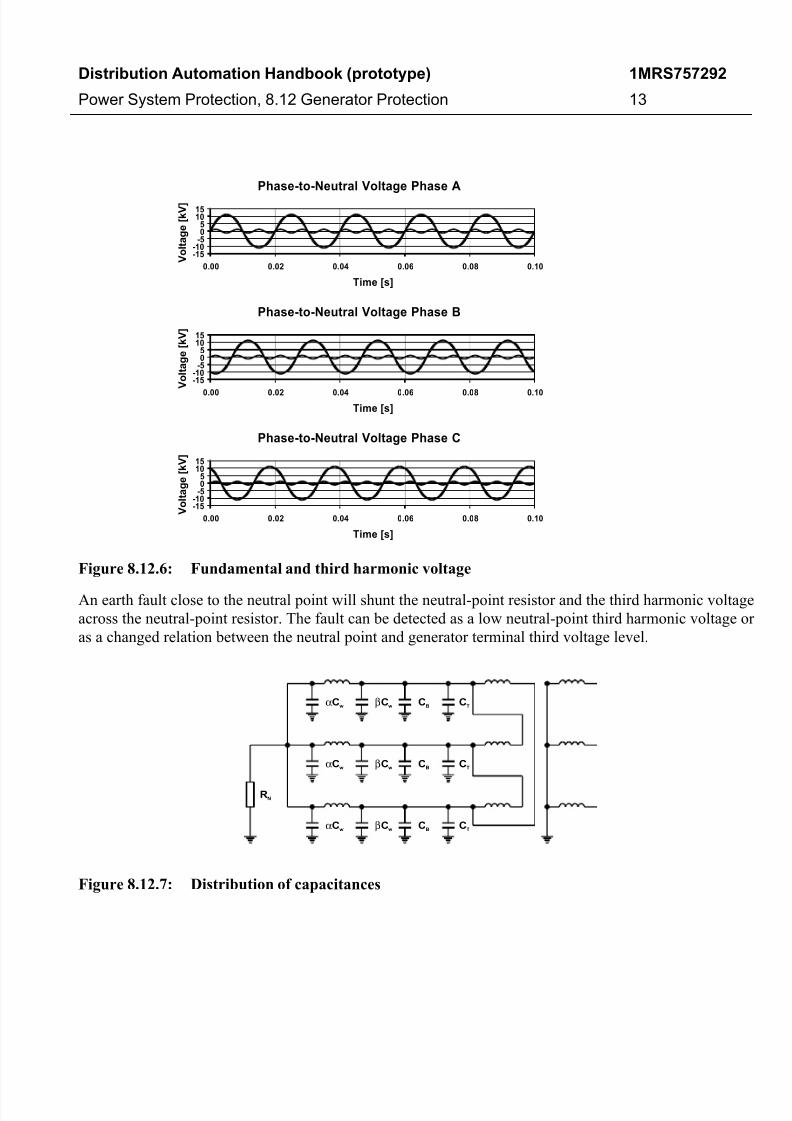
Figure 8.12.6: Fundamental and third harmonic voltage
An earth fault close to the neutral point will shunt the neutral-point resistor and the third harmonic voltage
across the neutral-point resistor. The fault can be detected as a low neutral-point third harmonic voltage or
as a changed relation between the neutral point and generator terminal third voltage level.
αCw
αCw
αCw
βCw
βCw
βCw
CB
CB
CB
CT
CT
CT
RN
Figure 8.12.7: Distribution of capacitances

7/27/2019 136681563 ABB Handbook Generator Protection 757292 ENa
http://slidepdf.com/reader/full/136681563-abb-handbook-generator-protection-757292-ena 14/36
Distribution Automation Handbook (prototype)
Power System Protection, 8.12 Generator Protection
1MRS757292
14
RN 3 Cα W
E3
3 ( C +C +C )β W B T·
Figure 8.12.8: Equivalent circuit for third harmonic
Normal Operation
Neutral
Terminal
E3,max
E3,min
V3,T
V3,N
Earth Fault at Neutral
Neutral
Terminal
E3,max
E3,min
V3,T
V3,N
Earth Fault at Terminal
Neutral
Terminal
E3,max
E3,min V3,T
V3,N
Figure 8.12.9: Third harmonic neutral-end earth-fault protection
7/27/2019 136681563 ABB Handbook Generator Protection 757292 ENa
http://slidepdf.com/reader/full/136681563-abb-handbook-generator-protection-757292-ena 15/36
Distribution Automation Handbook (prototype)
Power System Protection, 8.12 Generator Protection
1MRS757292
15
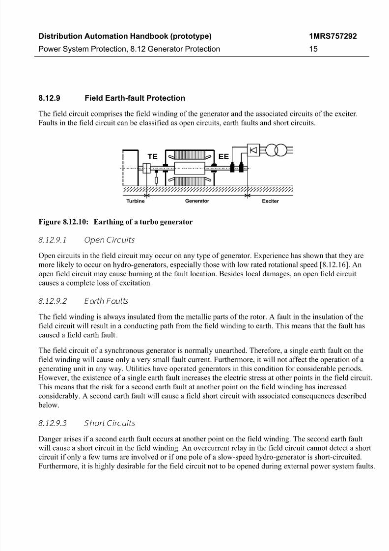
8.12.9 Field Earth-fault Protection
The field circuit comprises the field winding of the generator and the associated circuits of the exciter.
Faults in the field circuit can be classified as open circuits, earth faults and short circuits.
EETE
Turbine Exciter Generator
Figure 8.12.10: Earthing of a turbo generator
8.12.9.1 Open Circu its
Open circuits in the field circuit may occur on any type of generator. Experience has shown that they are
more likely to occur on hydro-generators, especially those with low rated rotational speed [8.12.16]. An
open field circuit may cause burning at the fault location. Besides local damages, an open field circuit
causes a complete loss of excitation.
8.12.9.2 Earth Fault s
The field winding is always insulated from the metallic parts of the rotor. A fault in the insulation of the
field circuit will result in a conducting path from the field winding to earth. This means that the fault has
caused a field earth fault.
The field circuit of a synchronous generator is normally unearthed. Therefore, a single earth fault on the
field winding will cause only a very small fault current. Furthermore, it will not affect the operation of a
generating unit in any way. Utilities have operated generators in this condition for considerable periods.
However, the existence of a single earth fault increases the electric stress at other points in the field circuit.
This means that the risk for a second earth fault at another point on the field winding has increasedconsiderably. A second earth fault will cause a field short circuit with associated consequences described
below.
8.12.9.3 Sho rt Circu its
Danger arises if a second earth fault occurs at another point on the field winding. The second earth fault
will cause a short circuit in the field winding. An overcurrent relay in the field circuit cannot detect a short
circuit if only a few turns are involved or if one pole of a slow-speed hydro-generator is short-circuited.
Furthermore, it is highly desirable for the field circuit not to be opened during external power system faults.
7/27/2019 136681563 ABB Handbook Generator Protection 757292 ENa
http://slidepdf.com/reader/full/136681563-abb-handbook-generator-protection-757292-ena 16/36
Distribution Automation Handbook (prototype)
Power System Protection, 8.12 Generator Protection
1MRS757292
16
Such faults may cause high currents to flow in the field circuit. Therefore, field overcurrent protections are
uncommon [8.12.16].
The normal field current of a large generator is considerable. The fault current caused by the short circuit
may very rapidly cause serious damage at the fault locations.
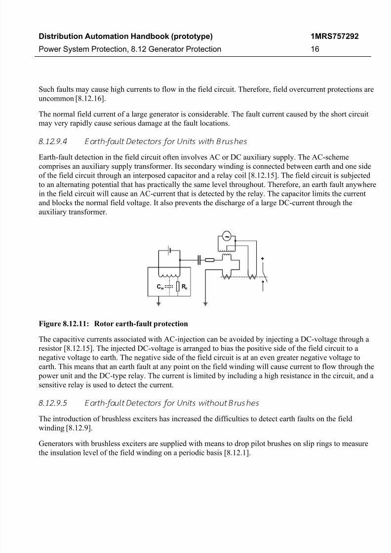
8.12.9.4 Earth-fault Detectors for Units with Bru shes
Earth-fault detection in the field circuit often involves AC or DC auxiliary supply. The AC-scheme
comprises an auxiliary supply transformer. Its secondary winding is connected between earth and one side
of the field circuit through an interposed capacitor and a relay coil [8.12.15]. The field circuit is subjected
to an alternating potential that has practically the same level throughout. Therefore, an earth fault anywhere
in the field circuit will cause an AC-current that is detected by the relay. The capacitor limits the currentand blocks the normal field voltage. It also prevents the discharge of a large DC-current through the
auxiliary transformer.
RECW
+
~
Figure 8.12.11: Rotor earth-fault protection
The capacitive currents associated with AC-injection can be avoided by injecting a DC-voltage through a
resistor [8.12.15]. The injected DC-voltage is arranged to bias the positive side of the field circuit to a
negative voltage to earth. The negative side of the field circuit is at an even greater negative voltage to
earth. This means that an earth fault at any point on the field winding will cause current to flow through the
power unit and the DC-type relay. The current is limited by including a high resistance in the circuit, and a
sensitive relay is used to detect the current.
8.12.9.5 Earth-fault Detectors for Units witho ut Brus hes
The introduction of brushless exciters has increased the difficulties to detect earth faults on the field
winding [8.12.9].
Generators with brushless exciters are supplied with means to drop pilot brushes on slip rings to measure
the insulation level of the field winding on a periodic basis [8.12.1].

7/27/2019 136681563 ABB Handbook Generator Protection 757292 ENa
http://slidepdf.com/reader/full/136681563-abb-handbook-generator-protection-757292-ena 17/36
Distribution Automation Handbook (prototype)
Power System Protection, 8.12 Generator Protection
1MRS757292
17
8.12.10 Underexcitation Protection
The production of reactive power from a synchronous machine can be increased by increasing the
excitation current (the rotor current). The machine acts like a shunt capacitor. A synchronous machine can
consume reactive power if the excitation current is low enough. In this state, the machine acts like a shunt
reactor.
The acceptable limit for overexcitation (reactive production) depends on the prevailing active power
generation (consumption). The acceptable limit for underexcitation (reactive consumption) may or may not
depend on the active generation (consumption).
8.12.10.1 Underexcitat ion of Synchr ono us Machines
There are limits for the underexcitation of a synchronous machine. A reduction of the excitation current
weakens the coupling between the rotor and the external power system. The machine may lose the
synchronism and starts to operate like an induction machine. Then, the reactive consumption will increase.
Even if the machine does not lose synchronism, it may not be acceptable to operate in this state for a long
time. The underexcitation increases the generation of heat in the end region of the synchronous machine.
The local heating may damage the insulation of the stator winding and even the iron core.
8.12.10.2 Lo ss of Excitat io n
A fault in the Automatic Voltage Regulator (AVR) or in the excitation system may cause a total loss of
excitation. A short circuit on the slip rings will reduce the excitation voltage down to zero. This will causea gradual reduction of the excitation current and eventually a loss of excitation. An open circuit in the field
circuit will also cause a total loss of excitation. When the field breaker is open, a high voltage is induced in
field winding and there is a risk for damages to the discharge resistor.
8.12.10.3 Und erexcitat io n Protectio n
Undercurrent relays connected in the field circuit have been used [8.12.5] for underexcitation protection.
Mason [8.12.5] and Sarma [8.12.7] both claim that the most reliable underexcitation protection is either an
MHO-relay or a directional impedance relay with its characteristic in the negative reactance area.
Many generators use a directional overcurrent relay for underexcitation protection. The underexcitationrelay shall trip the generator breaker and start the breaker failure protection. Underexcitation cannot occur
while the terminal voltage is low if the excitation system operates correctly. Therefore, the underexcitation
protection should use an undervoltage criterion. Underexcitation will not cause a low terminal voltage if the
generator is connected to a strong network or if there are several generating units in the power plant. In
such a case, the stator current of the faulty generator will increase. Therefore, the underexcitation
protection should use an overcurrent relay. Two criteria must be fulfilled before the underexcitation
equipment may trip the generator. The first criterion is the directional overcurrent relay has operated. The
second criterion is that either the undervoltage relay has operated or the (non-directional) overcurrent
protection has operated. It must however be mentioned that the undervoltage/overcurrent criteria cannot be
used for generators having a very high synchronous reactance, thus limiting the voltage drop and stator
current at loss of excitation.
7/27/2019 136681563 ABB Handbook Generator Protection 757292 ENa
http://slidepdf.com/reader/full/136681563-abb-handbook-generator-protection-757292-ena 18/36
Distribution Automation Handbook (prototype)
Power System Protection, 8.12 Generator Protection
1MRS757292
18
8.12.11 Overvoltage Protection
Some events can cause a high voltage on the generator both with the generator synchronized to the
network and before synchronization. The overvoltage can cause stress on insulation material and
overexcitation of transformer and generator.
The overvoltage protection system should, according to Sarma [8.12.7], have two steps if the generator
does not have an AVR. In thermal power plants, the first step should pick up if the voltage exceeds 125%.
For hydropower plants, the corresponding figure is 140%. The first step should trip without delay. The
second step should pick up if the voltage is higher than 110% and should have a dependent time
characteristic.
Most generators have two sets of voltage transformers. One set comprises three single-phase transformersand it energizes the protection equipment and the AVR. The second set may comprise only two single-
phase voltage transformers. This set energizes the overvoltage protection system. It is necessary to use two
sets of voltage transformers because otherwise the overvoltage protection system and the AVR do not have
independent input sources. Usually, a phase-to-phase voltage energizes the overvoltage protection system
to avoid unwanted operation at single phase-to-earth faults.
8.12.12 Reverse Power Protection
Sometimes the mechanical power from a prime mover may decrease so much that it does not cover bearing
losses and ventilation losses. Then the synchronous generator becomes a synchronous motor and starts to
take electric power from the rest of the power system. This operating state, where individual synchronousmachines operate as motors, implies no risk for the machine itself.
Often the motoring condition may imply that the turbine is in a very dangerous state. The task of the
reverse power protection is to protect the turbine and not to protect the generator itself. Generally, AC-
current and voltage energize the reverse power protection system and it trips the generator breaker.
Therefore, the reverse power protection is included in the generator protection.
Steam turbines overheat easily if the steam flow becomes too low or if the steam ceases to flow through the
turbine. Therefore, turbo-generators should have reverse power protection. Several contingencies may
cause reverse power. One is a break of the main steam pipe. A second is damage to one or more blades in
the steam turbine. The third is an inadvertent closing of the main stop valves. In the last case, it is highlydesirable to have a reliable reverse power protection. It may prevent damage to an otherwise undamaged
plant.
During the routine shutdown of many thermal power units, the reverse power protection gives the tripping
impulse to the generator breaker (the unit breaker). By doing so, the disconnection of the unit is prevented
before the mechanical power has become zero. Earlier disconnection would cause an acceleration of the
turbine generator at all routine shutdowns. This should have caused overspeed and high centrifugal stresses.
When the steam ceases to flow through a turbine, the cooling of the turbine blades will disappear. The
critical time to overheating of a steam turbine varies, according to Mason [8.12.5], from about 0.5 to
30 minutes, depending on the type of turbine. A high-pressure turbine with small and thin blades will

7/27/2019 136681563 ABB Handbook Generator Protection 757292 ENa
http://slidepdf.com/reader/full/136681563-abb-handbook-generator-protection-757292-ena 19/36
Distribution Automation Handbook (prototype)
Power System Protection, 8.12 Generator Protection
1MRS757292
19
overheat more easily than a low-pressure turbine with long and heavy blades. The conditions vary from
turbine to turbine, and it is necessary to ask the turbine manufacturer in each case. It is also prudent tomeasure the reverse power during the commissioning of new units.
A hydro turbine that rotates in water with closed wicket gates will draw electric power from the rest of the
power system. This power will be about 10% of the rated power. If there is only air in the hydro turbine,
the power demand will fall to about 3%. It is prudent to measure these values during the commissioning.
Diesel engines should, according to Mason [8.12.5], have reverse power protection. The generator will take
about 15% of its rated power or more from the system. According to GEC [8.12.15], a stiff engine may
require perhaps 25% of the rated power to motor it. An engine that is well run in might need no more than
5%. According to Sarma [8.12.7], diesel engine units usually require reverse power protection with a
setting of 15% to 25%. It is necessary to obtain information from the engine manufacturer and to measurethe reverse power during commissioning.
A reverse power relay and a timer can provide adequate reverse power protection. The reverse power relay
can be a directional undercurrent relay that measures the current that flows from the generator to the
network (an underpower relay). It may also be a directional overcurrent relay that measures a current that
flows from the network to the generator (an overpower relay). There are few sensitive current relays that
can also withstand the normal load current continuously. The relay must also temporarily withstand the
fault current that may flow through the relay. The setting range of the timer should be from a few seconds
to some minutes.
Figure 8.12.12 illustrates the properties of reverse power protection with an underpower relay and with anoverpower relay. The underpower relay gives higher margin and provides better dependability. On the
other hand, the risk for unwanted operation immediately after synchronization may be higher. The
underpower relay should be set to trip if the active power from the generator is less than about 2%. The
overpower relay should be set to trip if the power flow from the network to the generator is higher than 1%.
Underpower Relay Overpower Relay
Q Q
P P
Operating pointwithoutturbine torque
Operating pointwithoutturbine torque
Margin Margin
OperateLine
OperateLine
Figure 8.12.12: Characteristics of the reverse power protection
The demands on the reverse power protection are increasing. An AIEE report [8.12.16] says that the
reverse power relays may only give an alarm immediately when power flows from the network to the
generator. The reverse power relay should trip if the power reversal persists long enough to cause damage
7/27/2019 136681563 ABB Handbook Generator Protection 757292 ENa
http://slidepdf.com/reader/full/136681563-abb-handbook-generator-protection-757292-ena 20/36
Distribution Automation Handbook (prototype)
Power System Protection, 8.12 Generator Protection
1MRS757292
20
to the turbine from overheating. A delay of at least one minute will be permissible between the times when
the power reversal starts and tripping should occur.
8.12.13 Unbalance Protection
Single-phase loads, series faults and unsymmetrical faults may cause continuous and temporary unbalance
loading of a synchronous machine. If the unbalanced loading is too high and persists too long, the rotor of
the machine overheats and becomes damaged. Equation (8.12.2) gives the stator phase currents of a three-
phase generator that carries balanced load.
)3
4 - f (2 I = I
)3
2 - f (2 I = I
)3
0 - f (2 I = I
c
b
a
π π
π π
π π
sin
sin
sin
⋅
⋅
⋅
(8.12.2)
Equation (8.12.3) gives the phase-to-earth stator voltages of a three-phase generator that carries balanced
load.
)+3
4 - f (2V =V
)+3
2 - f (2V =V
)+3
0 - f (2V =V
c
b
a
ϕ π
π
ϕ π
π
ϕ π
π
sin
sin
sin
⋅
⋅
⋅
(8.12.3)
8.12.13.1 Unb alanced Lo ading
The generator carries an unbalanced load if equations (8.12.2) and (8.12.3) do not hold true. A well-defined
description of unbalance is the relative amount of negative-sequence current n I I 2 that the generator
carries. Equation (8.12.4) defines the negative sequence current 2 I .
3
I a+ I a+ I = I
cb2
a2
⋅⋅ (8.12.4)
Here n I is the rated stator current of the machine. The relative negative-sequence current is therefore well
defined and it can be measured.
8.12.13.1.1 Causes of Unbalanced Loading
Unbalanced loading may produce more severe heating than balanced three-phase operation. Series faults
close to the generator will cause negative sequence currents. Unsymmetrical faults may produce more
7/27/2019 136681563 ABB Handbook Generator Protection 757292 ENa
http://slidepdf.com/reader/full/136681563-abb-handbook-generator-protection-757292-ena 21/36
Distribution Automation Handbook (prototype)
Power System Protection, 8.12 Generator Protection
1MRS757292
21
severe heating in three-phase synchronous machines than symmetrical faults. Typical conditions and
incidents that can cause unbalanced loading are:
• Single-phase loads close to the power plant
• Untransposed transmission circuits
• Unbalanced step-up transformers
• Series faults in the transmission network
• Series faults on the secondary side of the step-up transformer
• Series faults on the primary side of the step-up transformer
• Pole discrepancy in the generator breaker
• Unbalanced shunt faults close to the power plant
• Unbalanced shunt faults on the generator buswork
8.12.13.1.2 Consequences for the Generators
The rotor of a synchronous machine overheats quite rapidly if the generator carries negative-sequence
currents. The negative-sequence current generates a stator-MMF that rotates with the same speed as the
rotor but in the opposite direction. Seen from the rotor, this MMF has a frequency n f 2 , where n f is the
power frequency (50 or 60 Hz). The MMF induces voltages with a frequency n f 2 in the rotor and itswindings.
These voltages cause currents to flow in the rotor and associated windings. Due to the skin effect, these
currents flow close to the surface of metallic objects in the rotor. The penetration depth in magnetic steel is
less than one millimeter at 50 Hz. These currents will quickly heat: the rotor body, the slot wedges, the
retaining ring and the damper winding if there is one. These components are normally already under great
stress in large turbo-generators. If the negative-sequence current persists, the metal will melt and damage
the rotor structure.
The amount of negative-sequence current that the machine can tolerate depends on the design of the
generator.
8.12.13.1.3 Turbo-Generators
Generators without damper winding do not have well-defined paths for the induced double frequency
currents. The electromagnetic and thermal utilization increases steadily. This is especially true for the
rotors in turbo-generators. This means that the turbo-generators are very sensitive for unbalanced loading.
8.12.13.1.4 Hydro-Generators
Salient pole generators with damper windings (hydro-generators) have well-defined paths for the induced
double frequency currents. The currents flow mainly in the damper windings. Generally, hydro-generators
7/27/2019 136681563 ABB Handbook Generator Protection 757292 ENa
http://slidepdf.com/reader/full/136681563-abb-handbook-generator-protection-757292-ena 22/36
Distribution Automation Handbook (prototype)
Power System Protection, 8.12 Generator Protection
1MRS757292
22
have strong damper windings and they can withstand higher negative-sequence currents than the turbo-
generators can. There are very few hydro-generators without damper windings.
8.12.13.2 Con tinu ou s I 2 -capabil i ty
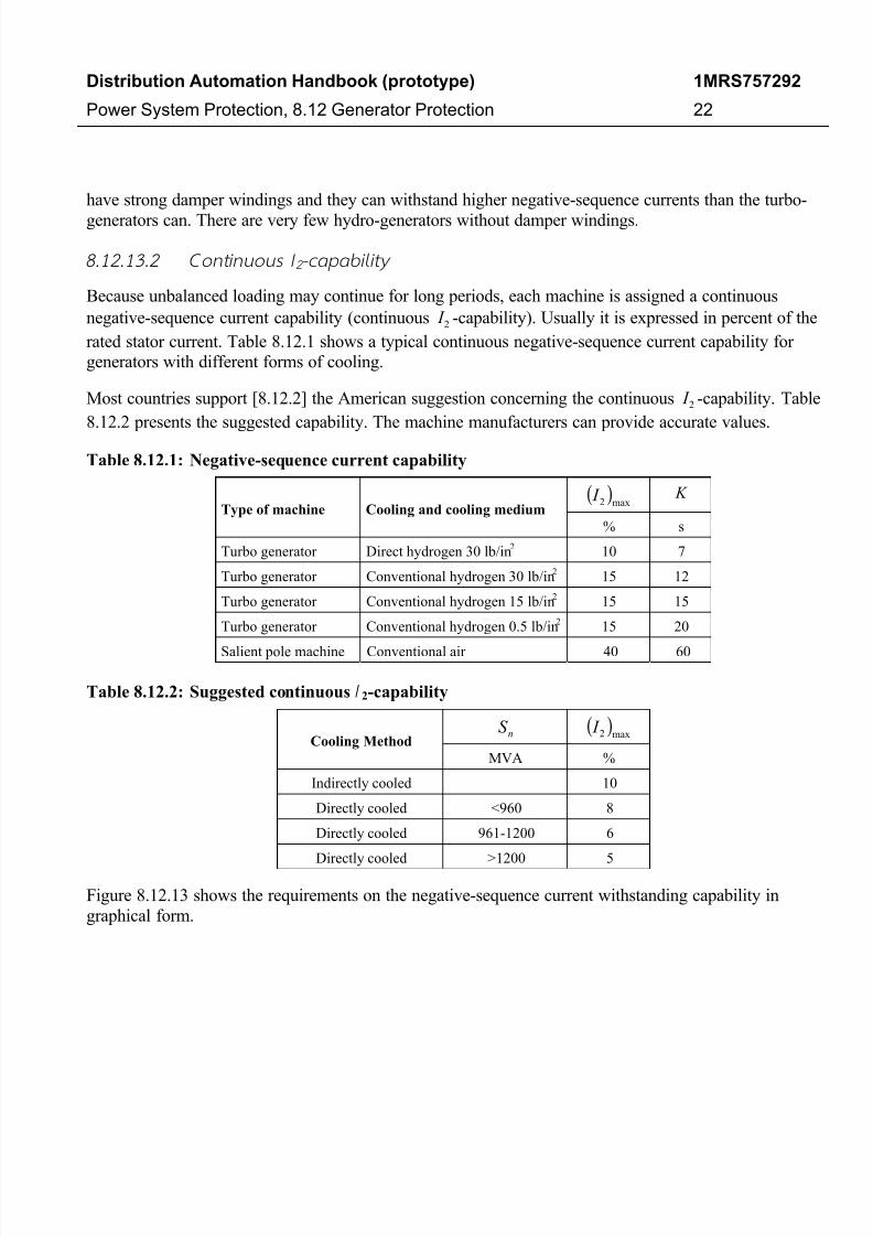
Because unbalanced loading may continue for long periods, each machine is assigned a continuous
negative-sequence current capability (continuous 2 I -capability). Usually it is expressed in percent of the
rated stator current. Table 8.12.1 shows a typical continuous negative-sequence current capability for
generators with different forms of cooling.
Most countries support [8.12.2] the American suggestion concerning the continuous 2 I -capability. Table
8.12.2 presents the suggested capability. The machine manufacturers can provide accurate values.
Table 8.12.1: Negative-sequence current capability
Type of machine Cooling and cooling medium( )
max2 I K
% s
Turbo generator Direct hydrogen 30 lb/in2 10 7
Turbo generator Conventional hydrogen 30 lb/in2 15 12
Turbo generator Conventional hydrogen 15 lb/in2 15 15
Turbo generator Conventional hydrogen 0.5 lb/in2 15 20
Salient pole machine Conventional air 40 60
Table 8.12.2: Suggested continuous I 2-capability
Cooling MethodnS ( )
max2 I
MVA %
Indirectly cooled 10
Directly cooled <960 8
Directly cooled 961-1200 6
Directly cooled >1200 5
Figure 8.12.13 shows the requirements on the negative-sequence current withstanding capability in
graphical form.
7/27/2019 136681563 ABB Handbook Generator Protection 757292 ENa
http://slidepdf.com/reader/full/136681563-abb-handbook-generator-protection-757292-ena 23/36
Distribution Automation Handbook (prototype)
Power System Protection, 8.12 Generator Protection
1MRS757292
23
Negative Sequence Current Capability (I2
,max)
0
2
4
6
8
10
0 500 1000 1500 2000
Rated Apparent Power Sn
[MVA]
P e r c e n t
Figure 8.12.13: Negative-sequence current withstand capability
8.12.13.3 Temporary I 2 -capabil i ty
The synchronous machine may carry large negative-sequence currents during fault conditions. Because
normal fault clearance times are short, the machine loses only little heat while the fault currents are
flowing. In addition, the heating caused by these currents may cause damage and therefore the input energy
must be limited. This means that a temporary negative-sequence current capability (temporary2 I -
capability) has to be defined. The length of time T [s] that a machine can operate with negative-sequence
current without danger of being damaged can be expressed in the form.
( ) =
T
K dt t i0
2
2 (8.12.5)
Here
( )t i2
2 is the negative-sequence current [p.u.] as a function of time
K is a constant
Equation (8.12.6) gives period T [s] that the generator can withstand a constant negative-sequence current
2 I [A].
2
2
=
I
I T n (8.12.6)
Here
n I is the rated current of the generator [A]
K is a constant that is typical for the type of generator [s]

7/27/2019 136681563 ABB Handbook Generator Protection 757292 ENa
http://slidepdf.com/reader/full/136681563-abb-handbook-generator-protection-757292-ena 24/36
Distribution Automation Handbook (prototype)
Power System Protection, 8.12 Generator Protection
1MRS757292
24
The constant K tells how many seconds the machine can withstand a negative-sequence current equal to
the rated current of the generator. The constant K depends on the size of the generator and the method of cooling. For most generators, the value is from 5 to 30 s, but for some hydro-generators it may be as high
as 60 s.
There are industry standards that determine the permissible unbalance for which a generator is designed
[8.12.4]. Equation (8.12.7) defines the requirements for turbo-generators with 800≤nS MVA.
10≥ K (8.12.7)
Equation (8.12.8) defines the requirements for 800>nS MVA.
( )160
80080000625.010 n
n
S S K
−=−×−≥ (8.12.8)
Figure 8.12.14 shows these requirements in a graphical form. A 500 MVA generator should have 10= K s
and a 1 600 MVA generator should have 5= K s. Figure 8.12.15 shows data on the negative-sequence
current capability. The ability of large generators to stand negative-sequence current is progressively
decreasing because their specific rating is still increasing, although their size has almost reached the limit
of the present material.
Negative Sequence Current Capability
0
5
10
15
0 500 1000 1500 2000
Rated Apparent Power Sn [MVA]
K [ s
e c o n d s ]
K=10-(Sn-800)/160
Figure 8.12.14: Continuous and short time unbalanced current capability of generators
7/27/2019 136681563 ABB Handbook Generator Protection 757292 ENa
http://slidepdf.com/reader/full/136681563-abb-handbook-generator-protection-757292-ena 25/36
Distribution Automation Handbook (prototype)
Power System Protection, 8.12 Generator Protection
1MRS757292
25
NEGATIVE SEQUENCE CURRENT CAPABILITY
1
10
100
1000
10000
M i n i m u m T
i m e [ s ]
0.01 0.1 1 10
Negative Sequence Current [pu]
L o w
I 2 m a x
H i g h I 2 m a x
Low K
High K
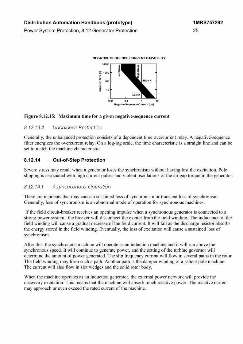
Figure 8.12.15: Maximum time for a given negative-sequence current
8.12.13.4 Unb alance Protecti on
Generally, the unbalanced protection consists of a dependent time overcurrent relay. A negative-sequence
filter energizes the overcurrent relay. On a log-log scale, the time characteristic is a straight line and can be
set to match the machine characteristic.
8.12.14 Out-of-Step Protection
Severe stress may result when a generator loses the synchronism without having lost the excitation. Pole
slipping is associated with high current pulses and violent oscillations of the air gap torque in the generator.
8.12.14.1 As yn ch ron ou s Operatio n
There are incidents that may cause a sustained loss of synchronism or transient loss of synchronism.
Generally, loss of synchronism is an abnormal mode of operation for synchronous machines.
If the field circuit-breaker receives an opening impulse when a synchronous generator is connected to a
strong power system, the breaker will disconnect the exciter from the field winding. The inductance of the
field winding will cause a gradual decrease of the field current. It will fall as the discharge resistor absorbs
the energy stored in the field winding. Eventually, the loss of excitation will cause a sustained loss of
synchronism.
After this, the synchronous machine will operate as an induction machine and it will run above the
synchronous speed. It will continue to generate power, and the setting of the turbine governor will
determine the amount of power generated. The slip frequency current will flow in several paths in the rotor.
The field winding may form such a path. Another path is the damper winding of a salient pole machine.
The current will also flow in slot wedges and the solid rotor body.
When the machine operates as an induction generator, the external power network will provide the
necessary excitation. This means that the machine will absorb much reactive power. The reactive current
may approach or even exceed the rated current of the machine.
7/27/2019 136681563 ABB Handbook Generator Protection 757292 ENa
http://slidepdf.com/reader/full/136681563-abb-handbook-generator-protection-757292-ena 26/36
Distribution Automation Handbook (prototype)
Power System Protection, 8.12 Generator Protection
1MRS757292
26
Synchronism can, according to GEC [8.12.15], be regained if the load is sufficiently reduced, but if this
does not occur within a few seconds, it is necessary to isolate the generator and then re-synchronize.
Out-of-step conditions can also occur as a consequence of a short circuit in the power system where the
fault clearance time is so long that synchronism cannot be maintained. This can be the consequence of a
backup protection function.
Out-of-step conditions can also occur if there are undamped oscillations between different groups of
generators in the power system.
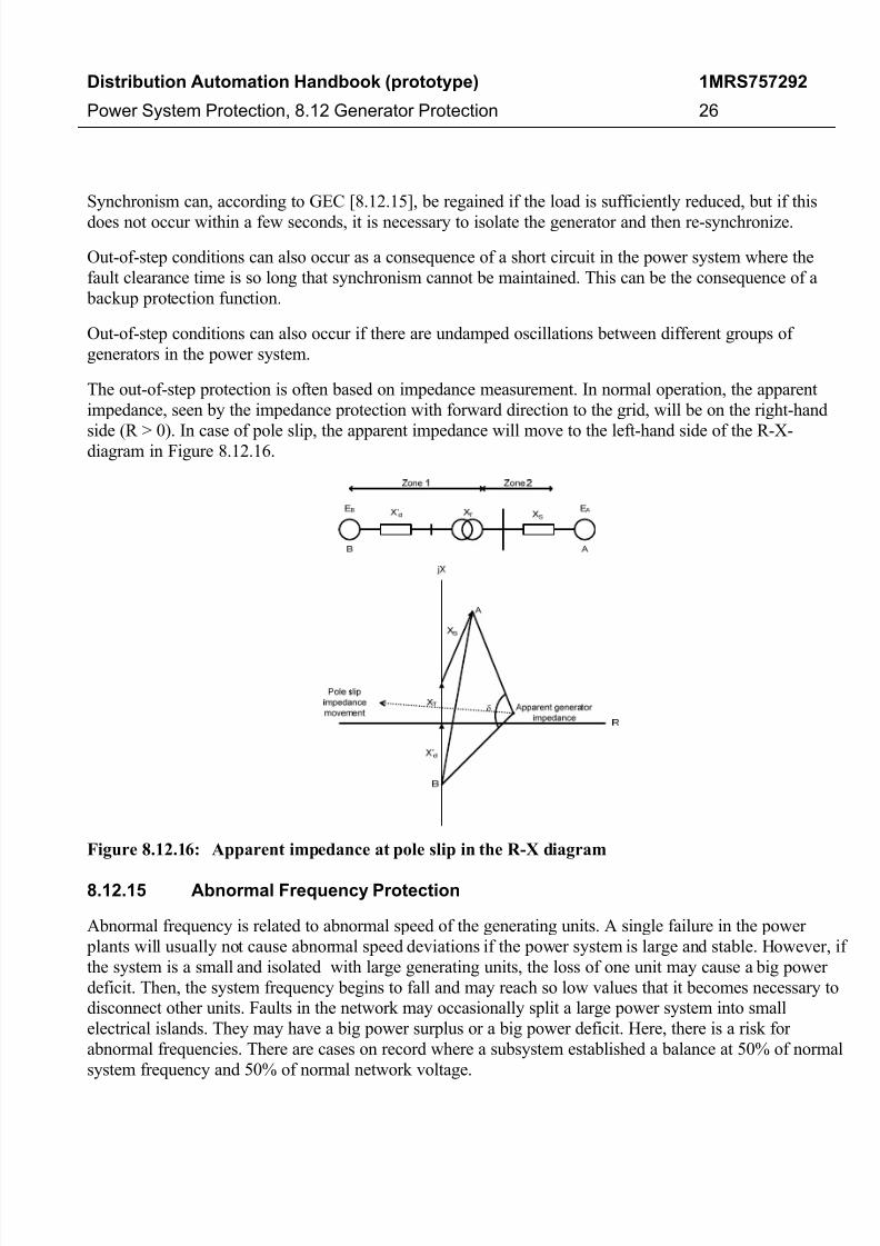
The out-of-step protection is often based on impedance measurement. In normal operation, the apparent
impedance, seen by the impedance protection with forward direction to the grid, will be on the right-hand
side (R > 0). In case of pole slip, the apparent impedance will move to the left-hand side of the R-X-diagram in Figure 8.12.16.
Figure 8.12.16: Apparent impedance at pole slip in the R-X diagram
8.12.15 Abnormal Frequency Protection
Abnormal frequency is related to abnormal speed of the generating units. A single failure in the power
plants will usually not cause abnormal speed deviations if the power system is large and stable. However, if
the system is a small and isolated with large generating units, the loss of one unit may cause a big power
deficit. Then, the system frequency begins to fall and may reach so low values that it becomes necessary to
disconnect other units. Faults in the network may occasionally split a large power system into small
electrical islands. They may have a big power surplus or a big power deficit. Here, there is a risk for
abnormal frequencies. There are cases on record where a subsystem established a balance at 50% of normal
system frequency and 50% of normal network voltage.
7/27/2019 136681563 ABB Handbook Generator Protection 757292 ENa
http://slidepdf.com/reader/full/136681563-abb-handbook-generator-protection-757292-ena 27/36
Distribution Automation Handbook (prototype)
Power System Protection, 8.12 Generator Protection
1MRS757292
27
8.12.15.1 Aim s of the Abn orm al Frequency Protect ion
The frequency control system shall provide the first line of defense against abnormal frequency. A load-
shedding system provides the second line of defense. Then, the abnormal frequency protection provides the
last defense line. One task is to prevent the operation of customer loads at abnormal frequencies. Another
task of the abnormal frequency protection is to prevent damage to power plant equipment.
Some utilities use an underfrequency relay to trip generating units to houseload when a widespread
blackout has occurred. The idea is to have the generating units in a hot standby state and ready for
synchronization. When the network operator has a voltage restored the transmission system, a new
generation will become available with a minimum time delay. Such actions aim at reducing the customer
interruption times instead of preventing loss of voltage.
There are two major considerations associated with operating power plants at abnormal system frequency:
• Protection of equipment from damage
• Prevention of cascading trips that lead to a complete blackout
8.12.15.2 Effects of Ab no rmal Frequen cy
There are no standards for abnormal frequency operation of synchronous generators. Reduced frequency
results in reduced ventilation. Therefore, operation at the reduced frequency should be at a reduced
apparent power. The underfrequency limitations on the generator, however, are usually less restrictive than
the limitations on steam turbines. Overfrequency is usually the result of a sudden load reduction. Therefore,overfrequency is associated with light load or no-load operation of the generator. Operation within the
allowable overfrequency limits of the turbine will not produce generator overheating as long as operation is
within the rated apparent power and 105% of the rated voltage. Abnormal frequency presents hazards to
other parts of the plant such as:
• Steam turbine vibrations and increased stresses on blades
• Reduced capacity of auxiliary equipment
• High temperatures caused by increased excitation current
• Overexcitation of transformers
8.12.15.3 Coord inat ion with Load Shedding
The aim of the frequency-controlled load shedding is to reestablish a balance between available generation
and load by disconnecting the load when the system frequency drops below certain levels. The amount of
load shedding varies from country to country and from region to region. Typical values range from 20% to
60% of system load. The generator underfrequency protection must not interfere with the load-shedding
system (selectivity).

7/27/2019 136681563 ABB Handbook Generator Protection 757292 ENa
http://slidepdf.com/reader/full/136681563-abb-handbook-generator-protection-757292-ena 28/36
Distribution Automation Handbook (prototype)
Power System Protection, 8.12 Generator Protection
1MRS757292
28
8.12.15.4 Real izat ion of Abn orm al Frequency Protect ion
All prime movers should have overspeed protection. The overspeed device may be a mechanical centrifugal
device or an overfrequency relay.
The setting of the overspeed device may be 108% to 115% for turbo-generators and 140% to 160% for
hydro turbines.
The overspeed protection may be a part of the prime mover, speed-governing system or generator
protection. The overspeed element should operate the main stop valve to shut down the prime mover. It
should also trip the generator circuit-breaker and the auxiliary breaker where the auxiliary power comes
from the generator buswork. By doing so, it is possible to prevent overfrequency operation of customer
loads and power plant auxiliaries.
The overspeed element should usually operate at 3% to 5% above the full-load rejection speed. The under-
frequency protections often have two steps. One frequency relay trips the unit breaker without delay if the
system frequency falls below 95%. Another frequency relay trips the unit if the frequency does not recover.
8.12.16 Inadvertent Energizing Protection
Operating errors, breaker head flashovers, control circuit malfunctions or a combination of these have
resulted in inadvertent or accidental energizing of off-line generators [8.12.12]. Many large generators have
been severely damaged, sometimes beyond repair [8.12.13].
8.12.16.1 Inadverten t Energ izing
Operating errors: The use of more complex breaker patterns has resulted in more frequent operating errors.
Even with extensive interlocks between unit breakers and disconnecters, there has been an increase in the
number of documented cases in which off-line units have been inadvertently energized through the high-
voltage switch.
Breaker head flashover: The extreme dielectric stress in breakers and the small contact gap spacing
associated with their high-speed interrupting requirement can lead to contact flashover. The risk of a
flashover is higher just before synchronization or just after the unit is removed from service.
8.12.16.2 Generator Respo nse to Inadvertent Energ izing
Three-phase energizing: When a generator is accidentally energized with a three-phase system voltage
while at low speed, it behaves like an induction motor. If the generator is connected to a strong network,
the stator current will be about 3 to 4 times the rated current.
Single-phase energizing: Single-phase energizing of a generator from the high-voltage system while at low
speed subjects the generator to a significant unbalance current. There will be no significant accelerating
torque if the voltage applied to the generator is single-phase. Breaker head flashover is the most frequent
cause of single-phase inadvertent energizing.
7/27/2019 136681563 ABB Handbook Generator Protection 757292 ENa
http://slidepdf.com/reader/full/136681563-abb-handbook-generator-protection-757292-ena 29/36
Distribution Automation Handbook (prototype)
Power System Protection, 8.12 Generator Protection
1MRS757292
29
8.12.16.3 Damage Caused by Inadvertent Energ izing
Turbo-generator damage: The initial effect of inadvertent energizing of a generator from standstill is rapid
heating in iron parts near the rotor surface. Slot wedges have little clamping load at standstill, resulting in
arcing between them and the rotor iron. The arc heating begins to melt the metals.
Steam turbine damage: During an inadvertent energizing incident, the generator acts as an induction motor
to drive the turbine. The generator starts to accelerate the turbine and the exciter. As it comes up to speed,
the unit passes through its natural torsional frequencies. Vibration, blade distortion and rubbing may cause
turbine damage if the energizing source is not removed soon enough. The blades in the steam turbine may
become overheated if the turbine continues to rotate at high speed without any steam flow. Bearing failure
due to insufficient lubrication can occur.
Hydro unit damage: Heating of the damper windings and the rotor material, combined with the lack of
proper ventilation, will cause damage quickly.
8.12.16.4 System s to Detect Inadverten t Energ izing
Dedicated protection systems are recommended to detect inadvertent energizing. Unlike conventional
protection systems that provide protection when equipment is in service, these schemes provide protection
when equipment is out of service. The most widely used dedicated protection systems are:
Frequency-supervised overcurrent relays: This system uses a frequency relay to supervise the trip output of
sensitively set instantaneous overcurrent relays. The overcurrent relays are automatically armed by the
frequency relay as the unit is taken offline and they remain armed while the unit is shut down.
Voltage-supervised overcurrent relays: This system utilizes undervoltage relays to supervise the trip output
of high-speed instantaneous overcurrent relays. The overcurrent relays are automatically armed by separate
undervoltage relays when the unit's field is de-energized and they remain armed while the unit is shut
down.
Auxiliary contact-enabled overcurrent relays: This system uses a combination of auxiliary contacts on
breakers and switches to enable and disable high-speed instantaneous phase overcurrent relays.
Distance relays: This scheme uses a distance relay located in the high-voltage switchyard that is set to look
into the machine. The relay should be set to detect the sum of the generator step-up transformer andmachine transient reactance with an appropriate margin.
Directional overcurrent relays: This scheme uses three directional phase overcurrent relays with very
inverse time characteristics. Voltage sensing is from the generator such that the overcurrent relays will pick
up on a current into the generator.
8.12.16.5 Schem es to Detect Breaker Head Flasho ver
Some of the dedicated schemes for inadvertent energizing can detect breaker head flashover. However, the
following schemes are widely used to detect breaker head flashover in the generator breaker or in the unit
breaker.
7/27/2019 136681563 ABB Handbook Generator Protection 757292 ENa
http://slidepdf.com/reader/full/136681563-abb-handbook-generator-protection-757292-ena 30/36
Distribution Automation Handbook (prototype)
Power System Protection, 8.12 Generator Protection
1MRS757292
30
Modified breaker failure scheme: An instantaneous overcurrent relay is connected in the neutral of the step-
up transformer. The relay is set to respond to a breaker pole flashover. A breaker auxiliary contact, which isclosed when the breaker is open, provides an additional start to the breaker-failure scheme. When the
breaker is open and one pole of the breaker flashes over (or two poles flash over), the resulting transformer
neutral current is detected by the overcurrent relay and the breaker failure scheme issues a tripping impulse.
Breaker pole disagreement: A current relay augments the conventional breaker pole disagreement scheme.
This relay senses whether any phase is below a certain low threshold level (indicating an open breaker
pole) while the other phase current is above a substantially higher threshold level (indicating a closed or
flashed over pole). Operation of the disagreement circuitry initiates breaker failure tripping.
8.12.17 Breaker Failure Protection
It is prudent to require that frequent faults with serious consequences shall be cleared even if one relay or
one switching device fails to operate when required.
It is sufficient to note that the probability of a failure to open is low but greater than zero. Few protection
engineers are prepared to recommend their companies to neglect the risk of breaker failure.
Sometimes it is possible to rely on remote backup protection. By introducing breaker failure protection for
the generator breaker and the unit breaker, it is possible to reduce the time for backup fault clearance. Often
it is less expensive to install a local backup protection and breaker failure protection than to reinforce the
power system for longer fault clearance times.
It is a common practice to use breaker failure protection with three or four overcurrent relays and a timer.
The breaker failure protection checks if all phase currents, and sometimes also the residual current, fall to
zero within a certain time after the operation of protection system. Usually the timer is set to operate after
150 to 200 milliseconds. If all currents are detected to have dropped out, the circuit-breaker has interrupted
the current and no further action is necessary. If this is not true, the breaker failure protection trips the
adjacent circuit-breakers.
7/27/2019 136681563 ABB Handbook Generator Protection 757292 ENa
http://slidepdf.com/reader/full/136681563-abb-handbook-generator-protection-757292-ena 31/36
Distribution Automation Handbook (prototype)
Power System Protection, 8.12 Generator Protection
1MRS757292
31
References
[8.12.1] Blackburn, J.L.: "Protective Relaying, Principles and Applications", Marcel Dekker, New
York, 1987.
[8.12.2] Glebov, I.A., Danilevich, J.B. & Mamikoniants, L.G.: "Abnormal Operation Conditions of
Large Synchronous Generators and their Influence on Design and Performance in a Power
System", Report 11-07, CIGRE-Session, Paris, 1976.
[8.12.3] Griffin, C.H. & Pope, J. W: "Generator Ground Fault Protection Using Overcurrent,
Overvoltage, and Undervoltage Relays", IEEE Trans. on Power Apparatus and Systems, vol.
PAS-101, no. 12, pp. 4490-4501, December 1982.
[8.12.4] Horowitz, S.H. & Phadke, A.G.: "Power System Relaying", Research Studies Press and John
Wiley & Sons, Taunton and New York, 1992.
[8.12.5] Mason, C.R.: "A New Loss-of-Excitation Relay for Synchronous Generators", AIEE Trans.,
vol. 68, pt. II, pp. 1240-1245, 1949.
[8.12.6] Pohl, R.: "Eisenverbrennung durch Lichtbögen niedriger Stromstärke", AEG Mitteilungen, vol.
20, no. 1, pp. 36-41, January 1930.
[8.12.7] Sarma, M.S.: "Synchronous Machines (Their Theory, Stability, and Excitation Systems)",
Gordon and Breach, New York, 1979.
[8.12.8] Schlake, R.L., Buckley, G.W. & McPherson, G.: "Performance of Third Harmonic GroundFault Protection Schemes for Generator Stator Windings", IEEE Trans. on Power Apparatus
and Systems, vol. PAS-100, no. 7, pp. 3195-3202, July 1981.
[8.12.9] Ungrad, H., Winkler, W. & Wisniewski, A.: "Schutztechnik in Elektroenergisystemen.
Grundlagen, Stand der Technik, Neuentwicklungen", Springer-Verlag, Berlin, 1991.
[8.12.10] Wright, A. & Christopoulos, C.: "Electrical Power System Protection", Chapman & Hall,
London, 1993.
[8.12.11] "Electrical Transmission and Distribution Reference Book", 4th ed., Westinghouse Electric
Corporation, East Pittsburgh, 1959.
[8.12.12] "Impact of HV and EHV Transmission on Generator Protection", IEEE Committee Report,
IEEE Trans. on Power Delivery, vol. 8, no. 3, pp. 962-974, July 1993.
[8.12.13] "Inadvertent Energizing Protection of Synchronous Generators", IEEE Committee Report,
IEEE Trans. on Power Delivery, vol. 4, no. 2, pp. 965-977, April 1989.
[8.12.14] "Power System Protection", vol. 3, 2nd ed. Edited by The Electricity Council, Peter Peregrinus
Ltd., Stevenage, 1981.
[8.12.15] "Protective Relays Application Guide", Second Edition, GEC Measurement, 1975, 5th printing,
October 1983.

7/27/2019 136681563 ABB Handbook Generator Protection 757292 ENa
http://slidepdf.com/reader/full/136681563-abb-handbook-generator-protection-757292-ena 32/36
Distribution Automation Handbook (prototype)
Power System Protection, 8.12 Generator Protection
1MRS757292
32
[8.12.16] "Relay Protection of A-C Generators", AIEE Committee Report, AIEE Trans., vol. 70, pt. I, pp.275-282, 1951.
7/27/2019 136681563 ABB Handbook Generator Protection 757292 ENa
http://slidepdf.com/reader/full/136681563-abb-handbook-generator-protection-757292-ena 33/36
Document revision history
Document revision/date History
A / 07 October 2010 First revision
Disclaimer and Copyrights
The information in this document is subject to change without notice and should not be construed as a commitment by ABB
Oy. ABB Oy assumes no responsibility for any errors that may appear in this document.
In no event shall ABB Oy be liable for direct, indirect, special, incidental or consequential damages of any nature or kind
arising from the use of this document, nor shall ABB Oy be liable for incidental or consequential damages arising from use of
any software or hardware described in this document.
This document and parts thereof must not be reproduced or copied without written permission from ABB Oy, and the contents
thereof must not be imparted to a third party nor used for any unauthorized purpose.
The software or hardware described in this document is furnished under a license and may be used, copied, or disclosed only
in accordance with the terms of such license.
Copyright © 2010 ABB Oy
All rights reserved.
Trademarks
ABB is a registered trademark of ABB Group. All other brand or product names mentioned in this document may be
trademarks or registered trademarks of their respective holders.

7/27/2019 136681563 ABB Handbook Generator Protection 757292 ENa
http://slidepdf.com/reader/full/136681563-abb-handbook-generator-protection-757292-ena 34/36
This page is intentionally left blank.

7/27/2019 136681563 ABB Handbook Generator Protection 757292 ENa
http://slidepdf.com/reader/full/136681563-abb-handbook-generator-protection-757292-ena 35/36

7/27/2019 136681563 ABB Handbook Generator Protection 757292 ENa
http://slidepdf.com/reader/full/136681563-abb-handbook-generator-protection-757292-ena 36/36
©
C o p y r i g h t 2 0 1 1
A B B .
A l l r i g h t s r e s e r v e d .
1 M R S 7 5 7 2 9 2 A
Contact information
ABB Oy, Distribution AutomationP.O.Box 699Visiting address: Muottitie 2AFI-65101 Vaasa, FINLANDPhone: +358 10 22 11Fax: +358 10 22 41094
www.abb.com/substationautomation