136268-4 1-04 xs series op man - Parts Express · Xs1200. Operation Manual Xs Series Power...
24
Operation Manual Obtaining Other Language Versions: To obtain information in another language about the use of this product, please contact your local Crown Distributor. If you need assistance locating your local distributor, please contact Crown at 574-294-8000. This manual does not include all of the details of design, production, or variations of the equipment. Nor does it cover every possible situation which may arise during installation, operation or maintenance. The information provided in this manual was deemed accurate as of the publication date. However, updates to this information may have occurred. To obtain the latest version of this manual, please visit the Crown website at www.crownaudio.com. Trademark Notice: Crown and Amcron are registered trademarks of Crown International. Other trademarks are the property of their respective owners. Some models may be exported under the name Amcron. ® ©2004 by Crown Audio Inc., P.O. Box 1000, Elkhart, Indiana 46515-1000 U.S.A. Telephone: 574-294-8000 Xs Series 136268-4 1/04 Xs900 Xs4300 Xs700 Xs500 Xs1200
Transcript of 136268-4 1-04 xs series op man - Parts Express · Xs1200. Operation Manual Xs Series Power...
Operation Manual
Obtaining Other Language Versions: To obtain information in another language about the use of this product, please contact your local Crown Distributor. If you need assistance locating your local distributor, please contact Crown at 574-294-8000.
This manual does not include all of the details of design, production, or variations of the equipment. Nor does it cover every possible situation which may arise during installation, operation or maintenance.
The information provided in this manual was deemed accurate as of the publication date. However, updates to this information may have occurred. To obtain the latest version of this manual, please visit the Crown website at www.crownaudio.com.
Trademark Notice: Crown and Amcron are registered trademarks of Crown International. Other trademarks are the property of their respective owners.
Some models may be exported under the name Amcron.®
©2004 by Crown Audio Inc., P.O. Box 1000, Elkhart, Indiana 46515-1000 U.S.A. Telephone: 574-294-8000
Xs Series
136268-4 1/04
Xs900
Xs4300
Xs700
Xs500
Xs1200

Operation Manual
Xs Series Power Amplifiers
page 2
1) Read these instructions.2) Keep these instructions.3) Heed all warnings.4) Follow all instructions.5) Do not use this apparatus near water.6) Clean only with a dry cloth.7) Do not block any ventilation openings. Install
in accordance with the manufacturer’s instruc-tions.
8) Do not install near any heat sources such as radiators, heat registers, stoves, or other apparatus that produce heat.
9) Do not defeat the safety purpose of the polar-ized or grounding-type plug. A polarized plug has two blades with one wider than the other. A grounding-type plug has two blades and a third grounding prong. The wide blade or the third prong is provided for your safety. If the provided plug does not fit into your outlet, consult an electrician for replacement of the obsolete outlet.
10) Protect the power cord from being walked on or pinched, particularly at plugs, convenience receptacles, and the point where they exit from the apparatus.
11) Only use attachments/accessories specified by the manufacturer.
12) Use only with a cart, stand, bracket, or table specified by the manufacturer, or sold with the apparatus. When a cart is used, use caution when moving the cart/apparatus combination to avoid injury from tip-over.
13) Unplug this apparatus during lightning storms or when unused for long periods of time.
14) Refer all servicing to qualified service person-nel. Servicing is required when the apparatus has been damaged in any way, such as power-supply cord or plug is damaged, liquid has been spilled or objects have fallen into the apparatus, the apparatus has been exposed to rain or moisture, does not operate normally, or has been dropped.
15) To reduce the risk of fire or electric shock, do not expose this apparatus to rain or moisture.
TO PREVENT ELECTRIC SHOCK DO NOT REMOVE TOP OR BOTTOM COVERS. NO USER SERVICE-ABLE PARTS INSIDE. REFER SERVICING TO QUALIFIED SERVICE PERSONNEL.
À PRÉVENIR LE CHOC ÉLECTRIQUE N’ENLEVEZ PAS LES COUVERCLES. IL N’Y A PAS DES PAR-TIES SERVICEABLE À L’INTÉRIEUR. TOUS REPA-RATIONS DOIT ETRE FAIRE PAR PERSONNEL QUALIFIÉ SEULMENT.
IMPORTANT
Xs Series amplifiers require Class 2 output wiring.
MAGNETIC FIELD
CAUTION! Do not locate sensitive high-gain equip-ment such as preamplifiers or tape decks directly above or below the unit. Because this amplifier has a high power density, it has a strong magnetic field which can induce hum into unshielded devices that are located nearby. The field is strongest just above and below the unit.
If an equipment rack is used, we recommend locat-ing the amplifier(s) in the bottom of the rack and the preamplifier or other sensitive equipment at the top.
WATCH FOR THESE SYMBOLS:
The lightning bolt triangle is used to alert the user to the risk of electric shock.
The exclamation point triangle is used to alert the user to important operating or maintenance instruc-tions.
Important Safety Instructions
FCC COMPLIANCE NOTICEThis device complies with part 15 of the FCC rules. Operation is subject to the following two conditions: (1) This device may not cause harmful interference, and (2) this device must accept any interference received, including interference that may cause undesired operation.
CAUTION: Changes or modifications not expressly approved by the party responsible for compliance could void the user’s authority to operate the equipment.
NOTE: This equipment has been tested and found to comply with the limits for a Class B digital device, pursuant to part 15 of the FCC Rules. These limits are designed to provide reasonable protection against harmful interference in a residential installation. This equip-ment generates, uses, and can radiate radio frequency energy and, if not installed and used in accordance with the operation manual, may cause harmful interference to radio commu-nications. However, there is no guarantee that interference will not occur in a particular installation. If this equipment does cause harmful interference to radio or television recep-tion, which can be determined by turning the equipment off and on, the user is encouraged to try to correct the interference by one or more of the following measures:
• Reorient or relocate the receiving antenna.• Increase the separation between the equipment and receiver.• Connect the equipment into an outlet on a circuit different from that to which the receiver
is connected.• Consult the dealer or an experienced radio/TV technician for help.
page 3
Xs Series Power Amplifiers
Operation Manual
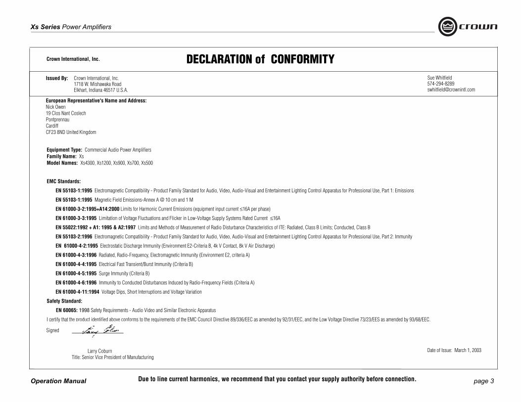
DECLARATION of CONFORMITYCrown International, Inc.
European Representative's Name and Address:Nick Owen19 Clos Nant CoslechPontprennauCardiffCF23 8ND United Kingdom
Equipment Type: Commercial Audio Power AmplifiersFamily Name: XsModel Names: Xs4300, Xs1200, Xs900, Xs700, Xs500
EMC Standards:
EN 55103-1:1995 Electromagnetic Compatibility - Product Family Standard for Audio, Video, Audio-Visual and Entertainment Lighting Control Apparatus for Professional Use, Part 1: Emissions
EN 55103-1:1995 Magnetic Field Emissions-Annex A @ 10 cm and 1 M
EN 61000-3-2:1995+A14:2000 Limits for Harmonic Current Emissions (equipment input current ≤16A per phase)
EN 61000-3-3:1995 Limitation of Voltage Fluctuations and Flicker in Low-Voltage Supply Systems Rated Current ≤16A
EN 55022:1992 + A1: 1995 & A2:1997 Limits and Methods of Measurement of Radio Disturbance Characteristics of ITE: Radiated, Class B Limits; Conducted, Class B
EN 55103-2:1996 Electromagnetic Compatibility - Product Family Standard for Audio, Video, Audio-Visual and Entertainment Lighting Control Apparatus for Professional Use, Part 2: Immunity
EN 61000-4-2:1995 Electrostatic Discharge Immunity (Environment E2-Criteria B, 4k V Contact, 8k V Air Discharge)
EN 61000-4-3:1996 Radiated, Radio-Frequency, Electromagnetic Immunity (Environment E2, criteria A)
EN 61000-4-4:1995 Electrical Fast Transient/Burst Immunity (Criteria B)
EN 61000-4-5:1995 Surge Immunity (Criteria B)
EN 61000-4-6:1996 Immunity to Conducted Disturbances Induced by Radio-Frequency Fields (Criteria A)
EN 61000-4-11:1994 Voltage Dips, Short Interruptions and Voltage Variation
Safety Standard:
EN 60065: 1998 Safety Requirements - Audio Video and Similar Electronic Apparatus
I certify that the product identified above conforms to the requirements of the EMC Council Directive 89/336/EEC as amended by 92/31/EEC, and the Low Voltage Directive 73/23/EES as amended by 93/68/EEC.
Larry Coburn
Signed
Title: Senior Vice President of Manufacturing Date of Issue: March 1, 2003
Issued By: Crown International, Inc. 1718 W. Mishawaka Road Elkhart, Indiana 46517 U.S.A.
Due to line current harmonics, we recommend that you contact your supply authority before connection.
Operation Manual
Xs Series Power Amplifiers
page 4
Important Safety Instructions ........................................................... 2
Declaration of Conformity ................................................................ 3
1 Welcome ....................................................... 5
1.1 Features ............................................................................... 5
1.2 How to Use This Manual ...................................................... 5
2 Setup ............................................................ 6
2.1 Unpack Your Amplifier ........................................................ 6
2.2 Install Your Amplifier .......................................................... 6
2.3 Ensure Proper Cooling ....................................................... 6
2.4 Choose Input Wire and Connectors .................................... 7
2.5 Choose Output Wire and Connectors .................................. 7
2.6 Wire Your System ............................................................... 8
2.6.1 Stereo Mode .............................................................. 8
2.6.2 How to Parallel the Inputs........................................... 8
2.6.3 Bridge-Mono Mode ................................................... 9
2.7 Connect to AC Mains........................................................... 10
2.8 Protecting Your Speakers .................................................... 10
2.9 Startup Procedure............................................................ ... 10
3 Operation ....................................................... 11
3.1 Precautions........................................................................... 11
3.2 Front Panel Controls and Indicators ..................................... 12
3.3 Back Panel Controls and Connectors (2-channel models).....13
3.4 Back Panel Controls and Connectors (Xs4300).....................14
4 Advanced Features and Options ............................. 15
4.1 Protection Systems ...............................................................15
4.1.1 Output Current Limiting ...............................................15
4.1.2 DC Protection ..............................................................15
4.1.3 Circuit Breaker .............................................................15
4.1.4 Thermal Protection ......................................................15
5 Troubleshooting ............................................... 16
6 Specifications ................................................. 17
7 Service . ....................................................... 19
7.1 Worldwide Service .................................................................19
7.2 US and Canada Service ..........................................................19
7.2.1 Service at a US or Canada Service Center ...................19
7.2.2 Factory Service ............................................................19
7.2.3 Factory Service Shipping Instructions .........................19
8 Warranty ....................................................... 20
Crown Factory Service Information Form ..........................................23
Table of Contents
page 5
Xs Series Power Amplifiers
Operation Manual
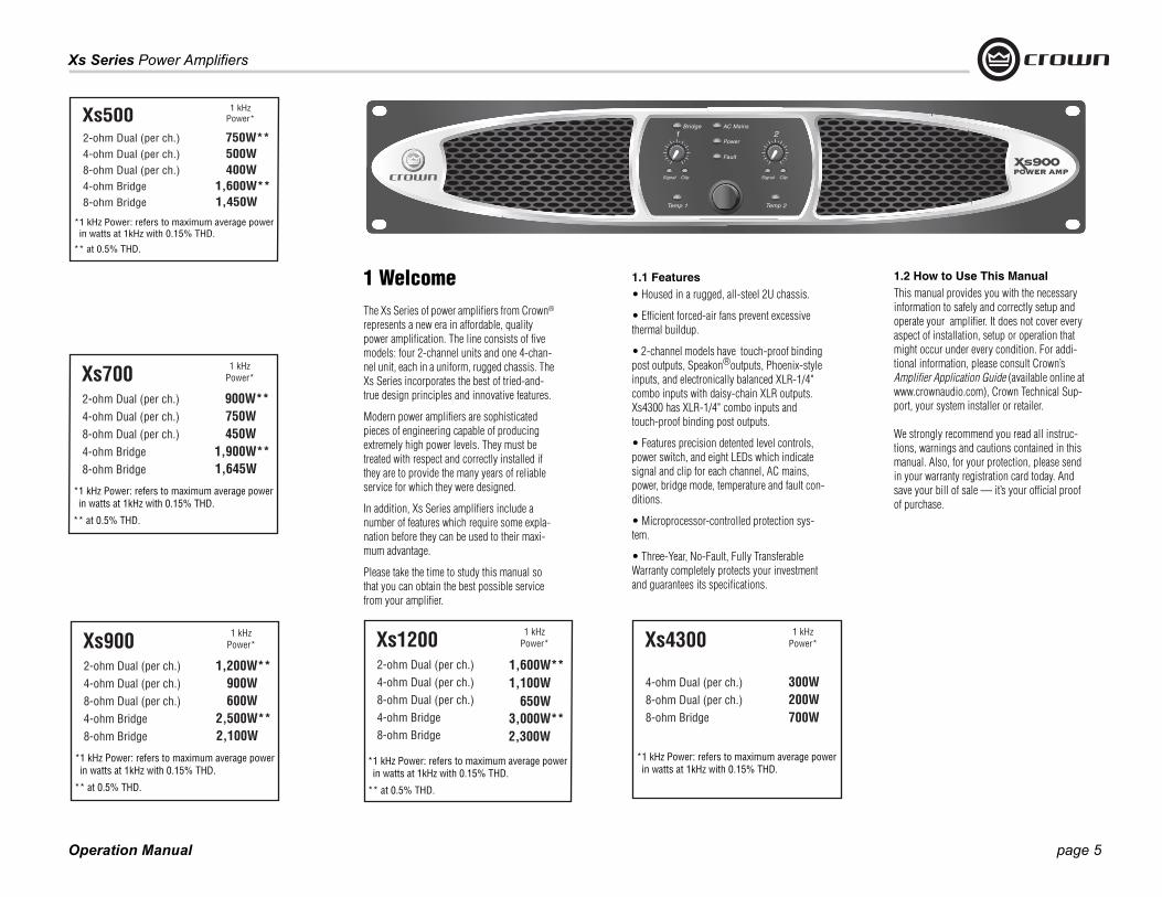
Xs5002-ohm Dual (per ch.) 750W**4-ohm Dual (per ch.) 500W8-ohm Dual (per ch.) 400W4-ohm Bridge 8-ohm Bridge
1 kHzPower*
*1 kHz Power: refers to maximum average power in watts at 1kHz with 0.15% THD.
1,450W1,600W**
** at 0.5% THD.
Xs7002-ohm Dual (per ch.) 900W**4-ohm Dual (per ch.) 750W8-ohm Dual (per ch.) 450W4-ohm Bridge 8-ohm Bridge
1 kHzPower*
*1 kHz Power: refers to maximum average power in watts at 1kHz with 0.15% THD.
1,645W1,900W**
** at 0.5% THD.
1 WelcomeThe Xs Series of power amplifiers from Crown® represents a new era in affordable, quality power amplification. The line consists of five models: four 2-channel units and one 4-chan-nel unit, each in a uniform, rugged chassis. The Xs Series incorporates the best of tried-and-true design principles and innovative features.
Modern power amplifiers are sophisticated pieces of engineering capable of producing extremely high power levels. They must be treated with respect and correctly installed if they are to provide the many years of reliable service for which they were designed.
In addition, Xs Series amplifiers include a number of features which require some expla-nation before they can be used to their maxi-mum advantage.
Please take the time to study this manual so that you can obtain the best possible service from your amplifier.
1.1 Features• Housed in a rugged, all-steel 2U chassis.
• Efficient forced-air fans prevent excessive thermal buildup.
• 2-channel models have touch-proof binding post outputs, Speakon®outputs, Phoenix-style inputs, and electronically balanced XLR-1/4" combo inputs with daisy-chain XLR outputs. Xs4300 has XLR-1/4" combo inputs and touch-proof binding post outputs.
• Features precision detented level controls, power switch, and eight LEDs which indicate signal and clip for each channel, AC mains, power, bridge mode, temperature and fault con-ditions.
• Microprocessor-controlled protection sys-tem.
• Three-Year, No-Fault, Fully Transferable Warranty completely protects your investment and guarantees its specifications.
1.2 How to Use This ManualThis manual provides you with the necessary information to safely and correctly setup and operate your amplifier. It does not cover every aspect of installation, setup or operation that might occur under every condition. For addi-tional information, please consult Crown’s Amplifier Application Guide (available online at www.crownaudio.com), Crown Technical Sup-port, your system installer or retailer.
We strongly recommend you read all instruc-tions, warnings and cautions contained in this manual. Also, for your protection, please send in your warranty registration card today. And save your bill of sale — it’s your official proof of purchase.
Xs9002-ohm Dual (per ch.) 4-ohm Dual (per ch.) 900W8-ohm Dual (per ch.) 600W4-ohm Bridge 8-ohm Bridge
1 kHzPower*
*1 kHz Power: refers to maximum average power in watts at 1kHz with 0.15% THD.
2,100W2,500W**
** at 0.5% THD.
1,200W**
Xs4300
4-ohm Dual (per ch.) 300W8-ohm Dual (per ch.) 200W8-ohm Bridge
1 kHzPower*
*1 kHz Power: refers to maximum average power in watts at 1kHz with 0.15% THD.
700W
Xs12002-ohm Dual (per ch.)4-ohm Dual (per ch.)8-ohm Dual (per ch.) 4-ohm Bridge 8-ohm Bridge
1 kHzPower*
*1 kHz Power: refers to maximum average power in watts at 1kHz with 0.15% THD.
2,300W3,000W**
** at 0.5% THD.
1,600W**
650W1,100W
Operation Manual
Xs Series Power Amplifiers
page 6
2.1 Unpack Your AmplifierPlease unpack and inspect your amplifier for any damage that may have occurred during transit. If damage is found, notify the transpor-tation company immediately. Only you can ini-tiate a claim for shipping damage. Crown will be happy to help as needed. Save the shipping carton as evidence of damage for the shipper’s inspection.
We also recommend that you save all packing materials so you will have them if you ever need to transport the unit. Never ship the unit without the factory pack.
YOU WILL NEED (not supplied):
• Input wiring cables
• Output wiring cables
Rack for mounting amplifier (or a stable surface for stacking)
WARNING: Before you start to set up your amplifier, make sure you read and observe the Important Safety Instruc-tions found at the beginning of thismanual.
2.2 Install Your AmplifierCAUTION: Before you begin, make sure your amplifier is disconnected from the power source, with the power switch in the “off” position and all level controls turned completely down (counterclock-wise).
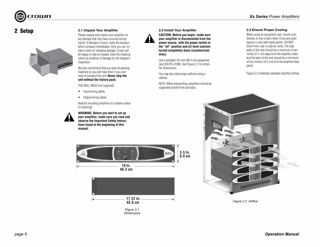
Use a standard 19-inch (48.3 cm) equipment rack (EIA RS-310B). See Figure 2.1 for ampli-fier dimensions.
You may also stack amps without using a cabinet.
NOTE: When transporting, amplifiers should be supported at both front and back.
2.3 Ensure Proper CoolingWhen using an equipment rack, mount units directly on top of each other. Close any open spaces in rack with blank panels. DO NOT block front, rear or side air vents. The side walls of the rack should be a minimum of two inches (5.1 cm) away from the amplifier sides, and the back of the rack should be a minimum of four inches (10.2 cm) from the amplifier back panel.
Figure 2.2 illustrates standard amplifier airflow.
2 Setup
Figure 2.2 Airflow
Figure 2.1 Dimensions

page 7
Xs Series Power Amplifiers
Operation Manual
2.4 Choose Input Wire and ConnectorsCrown recommends using pre-built or professionally wired bal-anced line (two-conductor plus shield), 22-24 gauge cables and connectors. At the amplifier inputs, use either:• 3-pin male XLR cable ends,• TRS or TS 1/4" phone plugs, or • Phoenix-style connectors (2-channel models only).
Unbalanced lines may be used, but may result in noise over long cable runs.
Figure 2.3 Combo Input Connector XLR Wiring, Balanced (Top) and
Unbalanced (Bottom)
Figure 2.5 Phoenix-Style Input Connector Wiring,
Balanced (Top) and Unbalanced (Bottom). Note Jumper Between �S� and ���
2 Setup
Figure 2.3 shows XLR wiring, Figure 2.4 shows 1/4" phone plug wiring, and Figure 2.5 shows Phoenix-style connector wiring.
NOTE: Custom wiring should only be performed by qual-ified personnel.
2.5 Choose Output Wire and ConnectorsCrown recommends using pre-built or professionally wired, high-quality, two- or four-conductor, heavy gauge speaker wire and connectors. You can use banana plugs, spade lugs, or bare wire for your output connectors (Figure 2.6). Also, in the 2-channel models, you can use a 4-pole Speakon® connector (Figure 2.7 and Table 1). To prevent the possibility of short-circuits, wrap or otherwise insulate exposed loudspeaker cable connectors.
Note: Binding post outputs on European models come with safety plugs installed to prevent European power-cord plugs from being inserted. The top & bottom entry positions for these connectors should therefore be used with European models.
Using the guidelines below, select the appropriate size of wire based on the distance from amplifier to speaker.
Distance Wire Size up to 25 ft. 16 AWG
26-40 ft. 14 AWG
41-60 ft. 12 AWG
61-100 ft. 10 AWG
101-150 ft. 8 AWG
151-250 ft. 6 AWG
CAUTION: Never use shielded cable for output wiring. Figure 2.6 Binding Post Output Wiring for 2-Channel Models
Figure 2.7 Left: Speakon®Output Connector on Back Panel
Right: Speakon®Cable Connector
TABLE 1: 2-CH MODELS OUTPUT ASSIGNMENTPIN CH PIN CH
1+ 2 1+ 1
1– 2 1– 1
2+ NC 2+ 2
2– NC 2– 2
CH 2 CH 1
Figure 2.4 Combo Input Connector 1/4"
Phone Wiring, Balanced (Top) and Unbalanced (Bottom)
Operation Manual
Xs Series Power Amplifiers
page 8
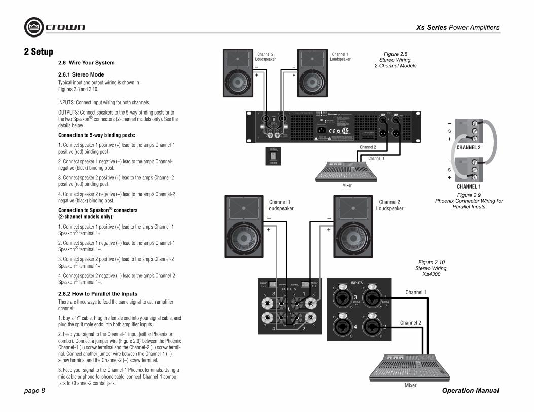
2.6 Wire Your System
2.6.1 Stereo Mode Typical input and output wiring is shown in Figures 2.8 and 2.10.
INPUTS: Connect input wiring for both channels.
OUTPUTS: Connect speakers to the 5-way binding posts or tothe two Speakon® connectors (2-channel models only). See the details below.
Connection to 5-way binding posts:
1. Connect speaker 1 positive (+) lead to the amp’s Channel-1positive (red) binding post.
2. Connect speaker 1 negative (–) lead to the amp’s Channel-1negative (black) binding post.
3. Connect speaker 2 positive (+) lead to the amp’s Channel-2positive (red) binding post.
4. Connect speaker 2 negative (–) lead to the amp’s Channel-2negative (black) binding post.
Connection to Speakon® connectors (2-channel models only):
1. Connect speaker 1 positive (+) lead to the amp’s Channel-1Speakon® terminal 1+.
2. Connect speaker 1 negative (–) lead to the amp’s Channel-1Speakon® terminal 1–.
3. Connect speaker 2 positive (+) lead to the amp’s Channel-2Speakon® terminal 1+.
4. Connect speaker 2 negative (–) lead to the amp’s Channel-2Speakon® terminal 1–.
2.6.2 How to Parallel the InputsThere are three ways to feed the same signal to each amplifier channel:
1. Buy a “Y” cable. Plug the female end into your signal cable, and plug the split male ends into both amplifier inputs.
2. Feed your signal to the Channel-1 input (either Phoenix or combo). Connect a jumper wire (Figure 2.9) between the Phoenix Channel-1 (+) screw terminal and the Channel-2 (+) screw termi-nal. Connect another jumper wire between the Channel-1 (–) screw terminal and the Channel-2 (–) screw terminal.
3. Feed your signal to the Channel-1 Phoenix terminals. Using a mic cable or phone-to-phone cable, connect Channel-1 combo jack to Channel-2 combo jack.
2 Setup
Figure 2.10 Stereo Wiring,
Xs4300
CHANNEL 2
CHANNEL 1
Figure 2.8 Stereo Wiring,
2-Channel Models
Figure 2.9 Phoenix Connector Wiring for
Parallel Inputs
page 9
Xs Series Power Amplifiers
Operation Manual
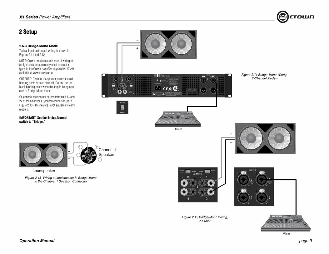
2.6.3 Bridge-Mono ModeTypical input and output wiring is shown in Figures 2.11 and 2.12.
NOTE: Crown provides a reference of wiring pin assignments for commonly used connector types in the Crown Amplifier Application Guide available at www.crownaudio.
OUTPUTS: Connect the speaker across the red binding posts of each channel. Do not use the black binding posts when the amp is being oper-ated in Bridge-Mono mode.
Or, connect the speaker across terminals 1+ and 2+ of the Channel 1 Speakon connector (as in Figure 2.13). This feature is not available in early models.‘
IMPORTANT: Set the Bridge/Normal switch to “Bridge.”
2 Setup
Figure 2.11 Bridge-Mono Wiring, 2-Channel Models
Figure 2.12 Bridge-Mono Wiring,Xs4300
Loudspeaker
Channel 1Speakon
Figure 2.13 Wiring a Loudspeaker in Bridge-Mono to the Channel 1 Speakon Connector

Operation Manual
Xs Series Power Amplifiers
page 10
NOTE: In Bridge-Mono mode, only the Channel 1 Level control is functional.
2.7 Connect to AC Mains Connect your amplifier to the AC mains power source (power outlet) with the supplied AC power cordset. First, connect the IEC end of the cordset to the IEC connector on the amplifier; then, plug the other end of the cordset to the AC mains. The AC Mains indication light on the front panel should be lit.
WARNING: The third prong of this connector (ground) is an important safety feature. Do not attempt to disable this ground connec-tion by using an adapter or other methods.
Amplifiers don’t create energy. The AC mains volt-age and current must be sufficient to deliver the power you expect. You must operate your amplifier from an AC mains power source with not more than a 10% variation above or a 15% variation below the amplifier’s specified line voltage and within the specfied frequency requirements (indicated on the amplifier’s back panel label). If you are unsure of the output voltage of your AC mains, please consult your electrician.
2.8 Protecting Your SpeakersIt’s wise to avoid clipping the amplifier signal. Not only does clipping sound bad, it can damage high-frequency drivers. To prevent clipping, insert a lim-iter between your mixer output and amplifier input. That way, no matter how strong a signal your mixer produces, the amplifier will not clip. Set the limiter threshold so that mixer signals above 0 on the mixer meters do not quite drive the amplifier into clipping.
Also, avoid sending strong subsonic signals to the amplifier. High-level, low-frequency signals from breath pops or dropped microphones can blow out drivers. To prevent subsonic signals, insert a high-pass filter between mixer output and amplifier input (or between mixer and limiter). Alternatively, switch in highpass filters at your mixer. Set the filter to as high a frequency as possible that does not affect your program. For example, try 35 Hz for music and
75 Hz for speech. On each mixer input channel, set the filter frequency just below the lowest fundamen-tal frequency of that channel's instrument.
2.9 Startup ProcedureUse the following procedure when first turning on your amplifier:
1. Turn down the level of your audio source.
2. Turn down the level controls of the amplifier.
3. Turn on the “Power” switch. The Power indica-tor should glow.
4. Turn up the level of your audio source to an optimum level.
5. Turn up the Level controls on the amplifier until the desired loudness or power level is achieved. NOTE: In Bridge-Mono mode, only the Channel 1 Level control is functional.
6. Turn down the level of your audio source to its normal range.
If you ever need to make any wiring or installation changes, don’t forget to disconnect the power cord.
For help with determining your system’s optimum gain structure (signal levels) please refer to the Crown Amplifier Application Guide, available online at www.crownaudio.com.
2 Setup

page 11
Xs Series Power Amplifiers
Operation Manual
3.1 PrecautionsYour amplifier is protected from internal and exter-nal faults, but you should still take the following precautions for optimum performance and safety:
1. Before use, your amplifier first must be config-ured for proper operation, including input and output wiring hookup. Improper wiring can result in serious operating difficulties. For information on wiring and configuration, please consult the Setup section of this manual or, for advanced setup techniques, consult Crown’s Amplifier Application Guide available online at www.crownaudio.com.
2. Use care when making connections, selecting signal sources and controlling the output level. The load you save may be your own!
3. Do not short the ground lead of an output cable to the input signal ground. This may form a ground loop and cause oscillations.
4. WARNING: Never connect the output to a power supply, battery or power main. Electrical shock may result.
3 Operation
5. Tampering with the circuitry, or making unau-thorized circuit changes may be hazardous and invalidates all agency listings.
6. Do not operate the amplifier with the red Clip LEDs constantly flashing.
7. Do not overdrive the mixer, which will cause clipped signal to be sent to the amplifier. Such signals will be reproduced with extreme accu-racy, and loudspeaker damage may result.
8. Do not operate the amplifier with less than the rated load impedance. Due to the amplifier’s output protection, such a configuration may result in premature clipping and speaker dam-age. Operating the Xs4300 with a 2-ohm load is not recommended, as the ampli-fier might shut down. The Xs500, 700 900 and 1200 can be used with a 2-ohm load.
Remember: Crown is not liable for damage that results from overdriving other system compo-nents.

Operation Manual
Xs Series Power Amplifiers
page 12
A B C ED F
G H I J
3 Operation
Figure 3.1 Front Panel Controls and Connectors
3.2 Front Panel Controls and Indicators
A. Cooling Vents
Front-to-rear forced airflow.
B. Gain Controls
Two or four grey rotary level controls, one for each chan-nel.
C. Bridge Indicator
Yellow LED indicates that amplifier is in Bridge-Mono mode (Channels 1 and 2, Channels 3 and 4 in Xs4300).
D. Power Indicator
Yellow LED indicates that amplifier has been turned on and AC power is available.
E. AC Mains Indicator
Red LED indicates that AC power is present at the power cord, even if the amplifier is not turned on.
F. Fault Indicator
Red LED illuminates when amplifier is in protect mode. Also illuminates briefly during normal power-up when amplifier is first switched on.
G. Signal Indicators
Two or four green LEDs, one for each channel, illuminates when the channel’s input signal level is above –40 dBu.
H. Clip Indicators
Two or four red LEDs, one for each channel, illumi-nates when the channel’s output signal is being over-driven.
I. Temp Indicator
Red LED, one for each channel, indicates that chan-nel(s) are in thermal protect mode.
J. Power Switch
Amplifier is on when the switch is depressed in the right-hand position. When the power switch is off and the unit is plugged into AC power, the amplifier is in standby mode; the AC mains are still connected to the unit.
page 13
Xs Series Power Amplifiers
Operation Manual
3 Operation
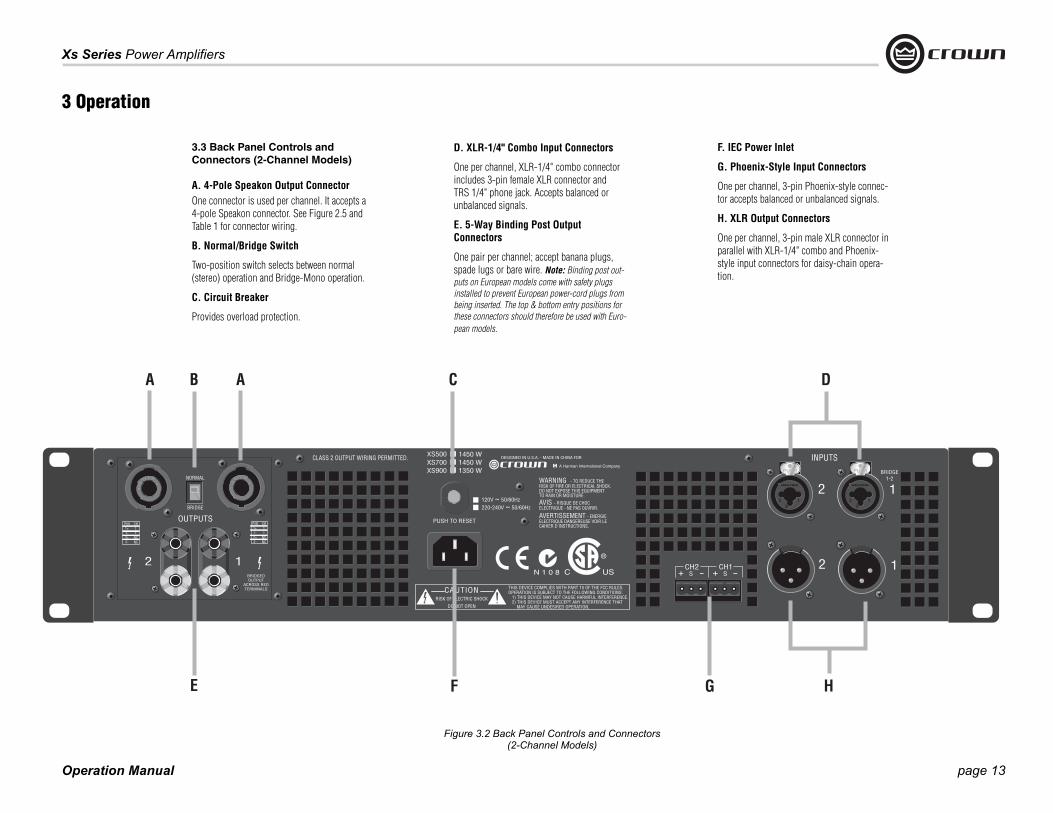
3.3 Back Panel Controls and Connectors (2-Channel Models)
A. 4-Pole Speakon Output ConnectorOne connector is used per channel. It accepts a 4-pole Speakon connector. See Figure 2.5 and Table 1 for connector wiring.
B. Normal/Bridge Switch
Two-position switch selects between normal(stereo) operation and Bridge-Mono operation.
C. Circuit Breaker
Provides overload protection.
D. XLR-1/4" Combo Input Connectors
One per channel, XLR-1/4" combo connector includes 3-pin female XLR connector and TRS 1/4" phone jack. Accepts balanced or unbalanced signals.
E. 5-Way Binding Post Output Connectors
One pair per channel; accept banana plugs, spade lugs or bare wire. Note: Binding post out-puts on European models come with safety plugs installed to prevent European power-cord plugs from being inserted. The top & bottom entry positions for these connectors should therefore be used with Euro-pean models.
Figure 3.2 Back Panel Controls and Connectors(2-Channel Models)
F. IEC Power Inlet
G. Phoenix-Style Input Connectors
One per channel, 3-pin Phoenix-style connec-tor accepts balanced or unbalanced signals.
H. XLR Output Connectors
One per channel, 3-pin male XLR connector in parallel with XLR-1/4" combo and Phoenix-style input connectors for daisy-chain opera-tion.

Operation Manual
Xs Series Power Amplifiers
page 14
3.4 Back Panel Controls andConnectors (Xs4300)
A. Normal/Bridge Switch(one per channel pair)
Two-position switch selects between normal (stereo) operation and Bridge-Mono operation.
B. Circuit Breaker
Provides overload protection.
C. XLR-1/4" Combo Input Connectors
One per channel, XLR-1/4" combo connector includes 3-pin female XLR connector and TRS 1/4" phone jack. Accepts balanced or unbalanced signals.
D. 5-Way Binding Post Output Connectors
One pair per channel; accept banana plugs, spade lugs or bare wire.
Note: Binding post outputs on European mod-els come with safety plugs installed to prevent European power-cord plugs from being inserted. The top & bottom entry positions for these connectors should therefore be used with European models.
E. IEC Power Inlet
3 Operation

page 15
Xs Series Power Amplifiers
Operation Manual
4 Advanced Features and Options
NOTE: For detailed information about these Crown amplifier features, please consult the Crown Amplifier Application Guide, available on the Crown website at www.crownaudio.com.
4.1 Protection SystemsYour Crown amplifier provides extensive pro-tection and diagnostic capabilities, including output current limiting, microprocessor-con-trolled DC protection, circuit breaker, and spe-cial thermal protection for the unit’s transformers.
4.1.1 Output Current LimitingOutput Current Limiting circuitry protects the amplifier output stage from damage caused by short-circuit loads.
4.1.2 DC ProtectionDC Protection disconnects the loudspeaker load in the event of an output DC offset exceed-ing 2V. In such an event the yellow Fault LED will illuminate (see Figure 4.1) and the ampli-fier channel will be muted. In the majority of cases, DC protection is indicative of a faulty amplifier channel, and will be accompanied by an illuminated Clip LED, even with no input connected and level controls set at minimum. If this is the case, contact your dealer or service center.
4.1.3 Circuit Breaker The high-voltage power supplies of your Crown amplifier are protected by a circuit breaker. The breaker rating varies depending on model and supply voltage as follows:
4.1.4 Thermal ProtectionThe Thermal Protection circuit will activate if the internal heatsink temperature exceeds proper operating temperatures (194 °F, 90 °C). When the heatsink temperature has fallen to a safe level, this protection circuit will automati-cally be reset. Principle causes of thermal pro-tection are:
1) Inadequate ventilation of the equipment rack2) Incorrect load impedance3) Output cable short circuit4) Blocked air vent5) Heatsinks in need of cleaning6) Cooling fan failure.
The cause of your amplifier’s thermal protection state should be determined and corrected as soon as possible. Without correction, the Ther-mal Protection circuit will typically reactivate.
Table 2: Circuit-Breaker Amperage Ratings
120V 220V 240V
Xs4300 18A 12A 12A
Xs1200 28A 22A 22A
Xs900 18A 12A 12A
Xs700 18A 12A 12A
Xs500 18A 12A 12A
Figure 4.1 Fault Indicator
Operation Manual
Xs Series Power Amplifiers
page 16
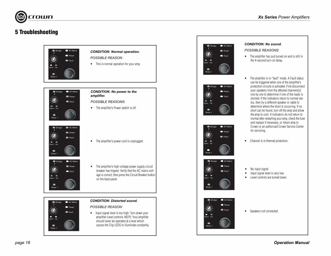
CONDITION: Normal operation.
POSSIBLE REASON:
• This is normal operation for your amp.
CONDITION: No power to the amplifier.
POSSIBLE REASONS:
• The amplifier’s Power switch is off.
CONDITION: Distorted sound.
POSSIBLE REASON:
• Input signal level is too high. Turn down your amplifier Level controls. NOTE: Your amplifier should never be operated at a level which causes the Clip LEDS to illuminate constantly.
5 Troubleshooting
CONDITION: No sound.
POSSIBLE REASONS:
• The amplifier has just turned on and is still in the 4-second turn-on delay.
• The amplifier is in “fault” mode. A Fault status can be triggered when one of the amplifier’s protection circuits is activated. First disconnect your speakers from the affected channels(s) one by one to determine if one of the loads is shorted. If the indicators return to normal sta-tus, then try a different speaker or cable to determine where the short is occurring. If no short can be found, turn off the amp and allow the amp to cool. If indicators do not return to normal after restarting your amp, check the fuse and replace if necessary, or return amp to Crown or an authorized Crown Service Center for servicing.
• Speakers not connected.
• No input signal• Input signal level is very low.• Level controls are turned down.
• The amplifier’s high-voltage power supply circuit breaker has tripped. Verify that the AC mains volt-age is correct, then press the Circuit Breaker button on the back panel.
• The amplifier’s power cord is unplugged. • Channel is in thermal protection.
page 17
Xs Series Power Amplifiers
Operation Manual
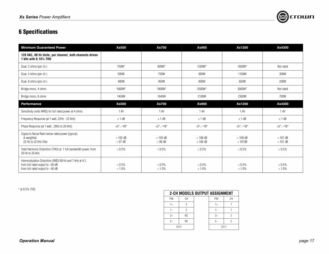
Minimum Guaranteed Power Xs500 Xs700 Xs900 Xs1200 Xs4300
120 VAC, 60 Hz Units, per channel, both channels driven1 kHz with 0.15% THD
Dual, 2 ohms (per ch.) 750W* 900W* 1200W* 1600W* Not rated
Dual, 4 ohms (per ch.) 500W 750W 900W 1100W 300W
Dual, 8 ohms (per ch.) 400W 450W 600W 650W 200W
Bridge mono, 4 ohms 1600W* 1900W* 2500W* 3000W* Not rated
Bridge mono, 8 ohms 1450W 1645W 2100W 2300W 700W
Performance Xs500 Xs700 Xs900 Xs1200 Xs4300
Sensitivity (volts RMS) for full rated power at 4 ohms 1.4V 1.4V 1.4V 1.4V 1.4V
Frequency Response (at 1 watt, 22Hz - 22 kHz) ± 1 dB ± 1 dB ± 1 dB ± 1 dB ± 1 dB
Phase Response (at 1 watt , 20Hz to 20 kHz) +5°, –18° +5°, –18° +5°, –18° +5°, –18° +5°, –18°
Signal to Noise Ratio below rated power (typical) A-weighted 22 Hz to 22 kHz filter
> 102 dB> 97 dB
> 103 dB> 98 dB
> 108 dB> 106 dB
> 109 dB> 107dB
> 107 dB> 101 dB
Total Harmonic Distortion (THD) at 1 full bandwidth power, from 20 Hz to 20 kHz
< 0.5% < 0.5% < 0.5% < 0.5% < 0.5%
Intermodulation Distortion (IMD) 60 Hz and 7 kHz at 4:1,from full rated output to –30 dBfrom full rated output to –40 dB
< 0.5%< 1.0%
< 0.5%< 1.0%
< 0.5%< 1.0%
< 0.5%< 1.0%
< 0.5%< 1.0%
6 Specifications
2-CH MODELS OUTPUT ASSIGNMENTPIN CH PIN CH
1+ 2 1+ 1
1– 2 1– 1
2+ NC 2+ 2
2– NC 2– 2
CH 2 CH 1
* at 0.5% THD.
Operation Manual
Xs Series Power Amplifiers
page 18
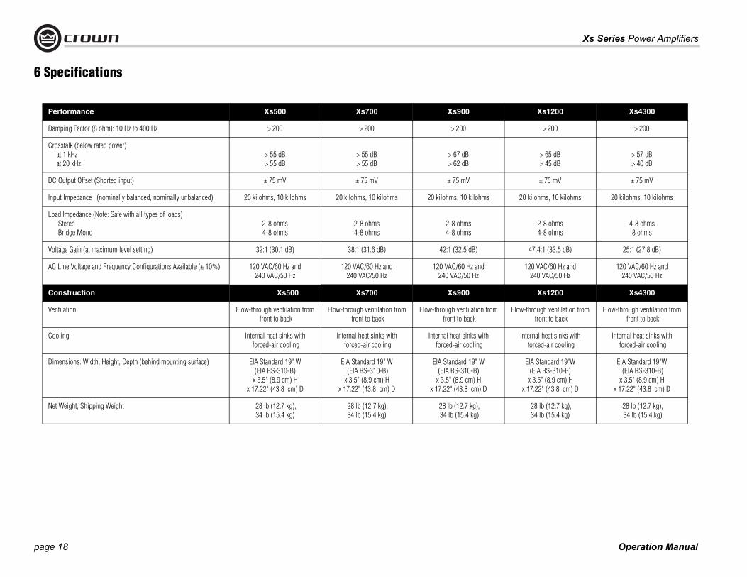
Performance Xs500 Xs700 Xs900 Xs1200 Xs4300
Damping Factor (8 ohm): 10 Hz to 400 Hz > 200 > 200 > 200 > 200 > 200
Crosstalk (below rated power) at 1 kHz at 20 kHz
> 55 dB> 55 dB
> 55 dB> 55 dB
> 67 dB> 62 dB
> 65 dB> 45 dB
> 57 dB> 40 dB
DC Output Offset (Shorted input) ± 75 mV ± 75 mV ± 75 mV ± 75 mV ± 75 mV
Input Impedance (nominally balanced, nominally unbalanced) 20 kilohms, 10 kilohms 20 kilohms, 10 kilohms 20 kilohms, 10 kilohms 20 kilohms, 10 kilohms 20 kilohms, 10 kilohms
Load Impedance (Note: Safe with all types of loads) Stereo Bridge Mono
2-8 ohms4-8 ohms
2-8 ohms4-8 ohms
2-8 ohms4-8 ohms
2-8 ohms4-8 ohms
4-8 ohms8 ohms
Voltage Gain (at maximum level setting) 32:1 (30.1 dB) 38:1 (31.6 dB) 42:1 (32.5 dB) 47.4:1 (33.5 dB) 25:1 (27.8 dB)
AC Line Voltage and Frequency Configurations Available (± 10%) 120 VAC/60 Hz and 240 VAC/50 Hz
120 VAC/60 Hz and 240 VAC/50 Hz
120 VAC/60 Hz and 240 VAC/50 Hz
120 VAC/60 Hz and 240 VAC/50 Hz
120 VAC/60 Hz and 240 VAC/50 Hz
Construction Xs500 Xs700 Xs900 Xs1200 Xs4300
Ventilation Flow-through ventilation from front to back
Flow-through ventilation from front to back
Flow-through ventilation from front to back
Flow-through ventilation from front to back
Flow-through ventilation from front to back
Cooling Internal heat sinks with forced-air cooling
Internal heat sinks with forced-air cooling
Internal heat sinks with forced-air cooling
Internal heat sinks with forced-air cooling
Internal heat sinks with forced-air cooling
Dimensions: Width, Height, Depth (behind mounting surface) EIA Standard 19" W (EIA RS-310-B)
x 3.5" (8.9 cm) H x 17.22" (43.8 cm) D
EIA Standard 19" W (EIA RS-310-B)x 3.5" (8.9 cm) H
x 17.22" (43.8 cm) D
EIA Standard 19" W (EIA RS-310-B)
x 3.5" (8.9 cm) Hx 17.22" (43.8 cm) D
EIA Standard 19"W (EIA RS-310-B)
x 3.5" (8.9 cm) H x 17.22" (43.8 cm) D
EIA Standard 19"W (EIA RS-310-B)x 3.5" (8.9 cm) H
x 17.22" (43.8 cm) D
Net Weight, Shipping Weight 28 lb (12.7 kg), 34 lb (15.4 kg)
28 lb (12.7 kg), 34 lb (15.4 kg)
28 lb (12.7 kg), 34 lb (15.4 kg)
28 lb (12.7 kg), 34 lb (15.4 kg)
28 lb (12.7 kg), 34 lb (15.4 kg)
6 Specifications
page 19
Xs Series Power Amplifiers
Operation Manual
Crown amplifiers are quality units that rarely require servicing. Before returning your unit for servicing, please contact Crown Technical Sup-port to verify the need for servicing.
This unit has very sophisticated circuitry which should only be serviced by a fully trained tech-nician. This is one reason why each unit bears the following label:
CAUTION: To prevent electric shock, do not remove covers. No user serviceable parts inside. Refer servicing to a quali-fied technician.
7.1 Worldwide ServiceService may be obtained from an authorized service center. (Contact your local Crown/Amcron representative or our office for a list of authorized service centers.) To obtain service, simply present the bill of sale as proof of pur-chase along with the defective unit to an autho-rized service center. They will handle the necessary paperwork and repair.
Remember to transport your unit in the original factory pack.
7.2 US and Canada ServiceService may be obtained in one of two ways: from an authorized service center or from the factory. You may choose either. It is important that you have your copy of the bill of sale as your proof of purchase.
7.2.1 Service at a US or Canada Service CenterThis method usually saves the most time and effort. Simply present your bill of sale along with the defective unit to an authorized service center to obtain service. They will handle the necessary paperwork and repair. Remember to transport the unit in the original factory pack. A
list of authorized service centers in your area can be obtained from the Crown website at www.crownaudio.com, or by calling Crown Customer Service.
7.2.2 Factory ServiceTo obtain factory service, fill out the service information page found in the back of this man-ual and send it along with your proof of pur-chase and the defective unit to the Crown factory.
For warranty service, we will pay for ground shipping both ways in the United States. Con-tact Crown Customer Service to obtain pre-paid shipping labels prior to sending the unit. Or, if you prefer, you may prepay the cost of shipping, and Crown will reimburse you. Send copies of the shipping receipts to Crown to receive reimbursement.
Your repaired unit will be returned via UPS ground. Please contact us if other arrange-ments are required.
7.2.3 Factory Service Shipping Instructions:1. Before sending a Crown product to the
factory for service, first call the Crown Ser-vice Department for a return authorization (RA) number.
2. Be sure to fill out the service information form that follows and enclose it with your shipment, either inside the box or in a packing slip envelope securely attached to the outside of the shipping carton. Do not send the service information form sepa-rately. If you are sending the unit from a Shipping Center, we recommend taping the form to the product. We also recom-mend recording the serial number and model before shipping for your reference.
3. To ensure the safe transportation of your unit to the factory, ship it in an original factory packing container. If you don’t have the original carton, you may obtain a prod-uct service foam-in-place shipping pack from the Crown Factory Service Depart-ment at the number listed below. For non-warranty service, you may also provide your own shipping pack, however we still recommend using a Crown Supplied Ship-ping Container. Minimum recommended requirements for materials are as follows: 275 P.S.I. burst test Double-Wall carton that allows for 2-inch solid Styrofoam on all six sides of unit or 3 inches of plastic bubble wrap on all six sides of unit; securely seal the package with an adequate carton sealing tape. Do not use light boxes or “peanuts.” Damage caused by poor packing cannot be covered under warranty.
4. Do not ship the unit in any kind of cabinet (wood or metal). Ignoring this warning may result in extensive damage to the unit and the cabinet. Accessories are not needed—do not send the product docu-mentation, cables and other hardware.
If you have any questions, please contact Crown Factory Service.
Crown Factory Service 1718 W. Mishawaka Rd.,
Elkhart, Indiana 46517 U.S.A.
Telephone: 574-294-8200800-342-6939 (North America,
Puerto Rico, and Virgin Islands only)
Facsimile: 574-294-8301 (Technical Support)574-294-8124 (Factory Service)
Internet: http://www.crownaudio.com
7 Service

Operation Manual
Xs Series Power Amplifiers
page 20
YEAR3SUMMARY OF WARRANTY
Crown International, 1718 West Mishawaka Road, Elkhart, Indiana 46517-4095 U.S.A. warrants to you, the ORIGINAL PURCHASER and ANY SUB-SEQUENT OWNER of each NEW Crown product, for a period of three (3) years from the date of purchase by the original purchaser (the “warranty period”) that the new Crown product is free of defects in materials and workmanship. We further warrant the new Crown product regardless of the reason for failure, except as excluded in this War-ranty.
ITEMS EXCLUDED FROM THIS CROWN WARRANTY
This Crown Warranty is in effect only for failure of a new Crown product which occurred within the Warranty Period. It does not cover any product which has been damaged because of any inten-tional misuse, accident, negligence, or loss which is covered under any of your insurance contracts. This Crown Warranty also does not extend to the new Crown product if the serial number has been defaced, altered, or removed.
WHAT THE WARRANTOR WILL DO
We will remedy any defect, regardless of the rea-son for failure (except as excluded), by repair, replacement, or refund. We may not elect refund unless you agree, or unless we are unable to pro-vide replacement, and repair is not practical or cannot be timely made. If a refund is elected, then you must make the defective or malfunctioning product available to us free and clear of all liens or other encumbrances. The refund will be equal to the actual purchase price, not including inter-
est, insurance, closing costs, and other finance charges less a reasonable depreciation on the product from the date of original purchase. War-ranty work can only be performed at our autho-rized service centers or at the factory. Warranty work for some products can only be performed at our factory. We will remedy the defect and ship the product from the service center or our factory within a reasonable time after receipt of the defec-tive product at our authorized service center or our factory. All expenses in remedying the defect, including surface shipping costs in the United States, will be borne by us. (You must bear the expense of shipping the product between any for-eign country and the port of entry in the United States including the return shipment, and all taxes, duties, and other customs fees for such for-eign shipments.)
HOW TO OBTAIN WARRANTY SERVICE
You must notify us of your need for warranty ser-vice within the warranty period. All components must be shipped in a factory pack, which, if needed, may be obtained from us free of charge. Corrective action will be taken within a reason-able time of the date of receipt of the defective product by us or our authorized service center. If the repairs made by us or our authorized service center are not satisfactory, notify us or our autho-rized service center immediately.
DISCLAIMER OF CONSEQUENTIAL AND INCIDENTAL DAMAGES
YOU ARE NOT ENTITLED TO RECOVER FROM US ANY INCIDENTAL DAMAGES RESULTING
FROM ANY DEFECT IN THE NEW CROWN PRODUCT. THIS INCLUDES ANY DAMAGE TO ANOTHER PRODUCT OR PRODUCTS RESULT-ING FROM SUCH A DEFECT. SOME STATES DO NOT ALLOW THE EXCLUSION OR LIMITATIONS OF INCIDENTAL OR CONSEQUENTIAL DAM-AGES, SO THE ABOVE LIMITATION OR EXCLU-SION MAY NOT APPLY TO YOU.
WARRANTY ALTERATIONS
No person has the authority to enlarge, amend, or modify this Crown Warranty. This Crown War-ranty is not extended by the length of time which you are deprived of the use of the new Crown product. Repairs and replacement parts provided under the terms of this Crown Warranty shall carry only the unexpired portion of this Crown Warranty.
DESIGN CHANGES
We reserve the right to change the design of any product from time to time without notice and with no obligation to make corresponding changes in products previously manufactured.
LEGAL REMEDIES OF PURCHASER
THIS CROWN WARRANTY GIVES YOU SPECIFIC LEGAL RIGHTS, YOU MAY ALSO HAVE OTHER RIGHTS WHICH VARY FROM STATE TO STATE. No action to enforce this Crown Warranty shall be commenced after expiration of the warranty period.
THIS STATEMENT OF WARRANTY SUPERSEDES ANY OTHERS CONTAINED IN THIS MANUAL FOR CROWN PRODUCTS. 12/01
8 WarrantyUNITED STATES & CANADA

page 21
Xs Series Power Amplifiers
Operation Manual
YEAR3
8 WarrantyWORLDWIDE EXCEPT USA & CANADA
SUMMARY OF WARRANTY
Crown International, 1718 West Mishawaka Road, Elkhart, Indiana 46517-4095 U.S.A. warrants to you, the ORIGINAL PURCHASER and ANY SUB-SEQUENT OWNER of each NEW Crown1 product, for a period of three (3) years from the date of pur-chase by the original purchaser (the “warranty period”) that the new Crown product is free of defects in materials and workmanship, and we further warrant the new Crown product regardless of the reason for failure, except as excluded in this Warranty.
1 Note: If your unit bears the name “Amcron,” please substitute it for the name “Crown” in this warranty.
ITEMS EXCLUDED FROM THIS CROWN-WARRANTY
This Crown Warranty is in effect only for failure of a new Crown product which occurred within the Warranty Period. It does not cover any product which has been damaged because of any inten-tional misuse, accident, negligence, or loss which is covered under any of your insurance contracts. This Crown Warranty also does not extend to the new Crown product if the serial number has been defaced, altered, or removed.
WHAT THE WARRANTOR WILL DO
We will remedy any defect, regardless of the rea-son for failure (except as excluded), by repair, replacement, or refund. We may not elect refund unless you agree, or unless we are unable to pro-vide replacement, and repair is not practical or cannot be timely made. If a refund is elected, then you must make the defective or malfunctioning product available to us free and clear of all liens or other encumbrances. The refund will be equal to the actual purchase price, not including inter-est, insurance, closing costs, and other finance charges less a reasonable depreciation on the product from the date of original purchase. War-ranty work can only be performed at our autho-rized service centers. We will remedy the defect and ship the product from the service center within a reasonable time after receipt of the defec-tive product at our authorized service center.
HOW TO OBTAIN WARRANTY SERVICE
You must notify your local Crown importer of your need for warranty service within the warranty period. All components must be shipped in the original box. Corrective action will be taken within a reasonable time of the date of receipt of the defective product by our authorized service center. If the repairs made by our authorized service cen-ter are not satisfactory, notify our authorized ser-vice center immediately.
DISCLAIMER OF CONSEQUENTIAL AND INCIDENTAL DAMAGES
YOU ARE NOT ENTITLED TO RECOVER FROM US ANY INCIDENTAL DAMAGES RESULTING FROM ANY DEFECT IN THE NEW CROWN PRODUCT. THIS INCLUDES ANY DAMAGE TO ANOTHER PRODUCT OR PRODUCTS RESULTING FROM SUCH A DEFECT.
WARRANTY ALTERATIONS
No person has the authority to enlarge, amend, or modify this Crown Warranty. This Crown Warranty is not extended by the length of time which you are deprived of the use of the new Crown product. Repairs and replacement parts provided under the terms of this Crown Warranty shall carry only the unexpired portion of this Crown Warranty.
DESIGN CHANGES
We reserve the right to change the design of any product from time to time without notice and with no obligation to make corresponding changes in products previously manufactured.
LEGAL REMEDIES OF PURCHASER
No action to enforce this Crown Warranty shall be commenced after expiration of the warranty period.
THIS STATEMENT OF WARRANTY SUPERSEDES ANY OTHERS CONTAINED IN THIS MANUAL FOR CROWN PRODUCTS. 7/01

Operation Manual
Xs Series Power Amplifiers
page 22
THIS PAGE INTENTIONALLY LEFT BLANK
page 23
Xs Series Power Amplifiers
Operation Manual
Crown Factory Service InformationShipping Address: Crown Factory Service, 1718 W. Mishawaka Rd., Elkhart, IN 46517
Phone: 1-800-342-6939 or 1-574-294-8200 Fax: 1-574-294-8124
Owner’s Name : _________________________________________________________________________________________________________________________________________________________________
Shipping Address: _______________________________________________________________________________________________________________________________________________________________
Phone Number: ________________________________Fax Number: ________________________________ Email ________________________________________________________________________________
Model: __________________________________________________________________________________ Serial Number: _________________________________________________________________________
Purchase Date : _________________________________________________________________________________________________________________________________________________________________
NATURE OF PROBLEM
(Be sure to describe the conditions that existed when the problem occurred and what attempts were made to correct it.)
_______________________________________________________________________________________________________________________________________________________________________________
_______________________________________________________________________________________________________________________________________________________________________________
_______________________________________________________________________________________________________________________________________________________________________________
_______________________________________________________________________________________________________________________________________________________________________________
_______________________________________________________________________________________________________________________________________________________________________________
_______________________________________________________________________________________________________________________________________________________________________________
_______________________________________________________________________________________________________________________________________________________________________________
_______________________________________________________________________________________________________________________________________________________________________________
Other equipment in system:____________________________________________________________________________________________________________________________________________________________
_______________________________________________________________________________________________________________________________________________________________________________
_______________________________________________________________________________________________________________________________________________________________________________
_______________________________________________________________________________________________________________________________________________________________________________
If warranty has expired, payment will be: ! Cash/Check ! Visa ! Master Card ! C.O.D. ! Purchase Order for Crown Dealer
Card Number:___________________________________ Exp. Date:___________________
Signature:______________________________________________________________________
ENCLOSE THIS PORTION WITH THE UNIT. DO NOT MAIL SEPARATELY.

![S90 XS/S70 XS Editor VST Owner's Manual - Yamaha · Starting the S90 XS/S70 XS Editor VST S90 XS/S70 XS Editor VST Owner’s Manual 6 13. In Quick Set Up, select [1] or [2]. nFor](https://static.fdocuments.us/doc/165x107/5fa5d7be5c20e054d9711161/s90-xss70-xs-editor-vst-owners-manual-yamaha-starting-the-s90-xss70-xs-editor.jpg)
![Data Structures UW CSE 190p Summer 2012. >>> xs = range(3) >>> xs = [1,2,3] >>> xs = [‘a’,’b’,’c’] >>> xs = [1, ‘a’, 3] >>> xs = [[1,2,3], [‘a’,’b’,’c’]]](https://static.fdocuments.us/doc/165x107/56649d925503460f94a78dee/data-structures-uw-cse-190p-summer-2012-xs-range3-xs-123.jpg)