131 - NFPA
166
131 EEM-1 Report of Committee on Electrical Equipment Maintenance Alan Reed, Chairnmn, Daniel Woodhead Company, 3411 Woodhead Dr., Northbrook, IL 60062 (Rep. National Safety Council) George O. Hunt, Vice Chairman, Monsanto Company, 800 N. Lindbergh Blvd., St. Louis, MO 63166 Richard W. Shaul,~ Recording Secretary, Nat'l. Electrical Manufacturers Assn., 155 East 44th St,, New York, NY 10017 C. Bangert, Jr., Equipment Section & Chairman NEMA Delegation C. T. Baxter, NEMA Industrial and Com- mercial Lighting Equipment Section Warren H. Cook, Western Electric Co., Inc. Leonard S. Corey, Eastman Kodak Co. Charles J. Elart, National Electrical Con- tractors Assn. C. Fred Hedlund, Factory Mutual Research Corp. Charles S. Helldoerier, National Electrical Testing Associatton, Inc. Ronald J. Kasper, Factory Insurance Assn. Z. J. Kruzic, NEMA Industrial Control & Systems Section L. E. LaFehr, International Association of Electrical Inspectors Robert J. Lawrle, Electrical Construction & Maintenance Richard L. Lloyd, National Electrical Code Committee Abbott H. Lucas, Electrical Fuse Manu- faeturem Guild Donald W. Lutz, Electrical Maintenance Engineering Association Ed Palkn, Sr., Plant Engineering Magazine J. M. Parker, International Brotherhood of EleetrlcalWorkers R. W. Plummer, Aluminum Company of America Carlton E. Schaad, American Insurance Association El. Dale Sheets, Proctor & Gamble Co. R. L. Schultz, James G. Biddle Co. R. F. Sorenson, St. Regis Paper Co. 13. H. St. OnI~e, Esso Research & Engineer- ing Co. K. W. Swain, NEMA Fuss Section William A. Weddendorf, Western Electric Co., Inc. Alternates. Robert M. Byrne, Electrical Fuss Manufacturers Guild (Alternate to A. H. Luca~) W. L. McKeithan, Westinghouse Electric Corp. (Alternate to C. Bangert, Jr.) tNonvoting. This list represents the membership at the time the Committee was balloted on the text of this edition. Since that time, changes in the membership may have occurred, The Committee on Electrical Equipment Maintenance recom- mends official adoption of NFPA No. 70B-T, Recommended Prac- tice for Electrical Equipment Maintenance. This report has been submitted to letter ballot of the committee which consists of 26 voting members of whom 79 have voted qffirmatively. Messrs. Bangert, Baxter, Cook, Lawrie, Lloyd, Swain and Weddendorf have voted negatively on one or more paragraphs of the report. This committee reports to the Association thro@h the Correlating Com- mittee of the National Electrical Code Committee. The Co~relating Committee • has voted to accept the report of the Electrical Equipment Maintenance Committee.
Transcript of 131 - NFPA

131 EEM-1
Report of Committee on Electrical Equipment Maintenance
Alan Reed, Chairnmn, Daniel Woodhead Company, 3411 Woodhead Dr., Northbrook, IL 60062
(Rep. National Safety Council)
George O. Hun t , Vice Chairman, Monsanto Company, 800 N. Lindbergh Blvd., St. Louis, MO 63166
Richard W. Shaul,~ Recording Secretary, Nat'l. Electrical Manufacturers Assn., 155 East 44th St,, New York, NY 10017
C. Banger t , J r . , Equipment Section & Chairman NEMA Delegation
C. T. Baxter, NEMA Industrial and Com- mercial Lighting Equipment Section
War ren H. Cook, Western Electric Co., Inc. L e o n a r d S. Corey, Eastman Kodak Co. Char les J. Elart, National Electrical Con-
tractors Assn. C. Fred Hed lund , Factory Mutual Research
Corp. Charles S. Helldoerier , National Electrical
Testing Associatton, Inc. Ronald J. Kasper , Factory Insurance Assn. Z. J. Kruzic, NEMA Industrial Control &
Systems Section L. E. LaFehr , International Association of
Electrical Inspectors Rober t J . Lawrle, Electrical Construction
& Maintenance Richard L. Lloyd, National Electrical Code
Committee
Abbott H. Lucas, Electrical Fuse Manu- faeturem Guild
Donald W. Lutz, Electrical Maintenance Engineering Association
Ed Palkn, Sr., Plant Engineering Magazine
J. M. Parker, International Brotherhood of Eleetrlcal Workers
R. W. Plummer, Aluminum Company of America
Car l ton E. Schaad, American Insurance Association
El. Dale Sheets, Proctor & Gamble Co.
R. L. Schultz, James G. Biddle Co.
R. F. Sorenson, St. Regis Paper Co.
13. H. St. OnI~e, Esso Research & Engineer- ing Co.
K. W. Swain, NEMA Fuss Section
William A. Weddendorf, Western Electric Co., Inc.
Alternates .
Rober t M. Byrne, Electrical Fuss Manufacturers Guild (Alternate to A. H. Luca~) W. L. McKei than , Westinghouse Electric Corp. (Alternate to C. Bangert, Jr.)
tNonvoting.
This list represents the membership at the time the Committee was balloted on the text of this edition. Since that time, changes in the membership may have occurred,
The Committee on Electrical Equipment Maintenance recom- mends official adoption of NFPA No. 70B-T, Recommended Prac- tice for Electrical Equipment Maintenance.
This report has been submitted to letter ballot of the committee which consists of 26 voting members of whom 79 have voted qffirmatively. Messrs. Bangert, Baxter, Cook, Lawrie, Lloyd, Swain and Weddendorf have voted negatively on one or more paragraphs of the report.
This committee reports to the Association thro@h the Correlating Com- mittee of the National Electrical Code Committee. The Co~relating Committee
• has voted to accept the report of the Electrical Equipment Maintenance Committee.

132 G E N E R A L 70B-7
Recommended Practice for
Electrical Equipment Maintenance
N F P A N o . 7 0 B - - 1 9 7 5
CHAPTER1--GENERAL.
1-1 Purpose . The purpose of this recommended practice is to reduce hazard to life and property that can result from failure or malfunction of industrial-type electrical systems and equipment. The first three chapters of these recommendations for an effective Elec- trical Preventive Maintenance (EPM) program have been prepared with the intent of providing a better understanding of benefits, both direct and intangible, that can be derived from a well-ad- ministered EPM program. This practice explains the function, requirements, and economic considerations that can be used to establish such a program.
1-2 Scope. This recommended practice is confined to preventive maintenance for industrial-type electrical systems and equipment, and is not intended to duplicate or supersede instructions that elec- trical manufacturers normally provide. Systems and equ ipment covered are those operating at 15 kV and below and are typical of those installed in industrial plants, institutional and commercial buildings, and large multifamily residential complexes. Consumer appliances and equipment intended primarily for use in the home are not included.
1-3 Definitions.
1-3.1 Electrical Preventive Maintenance (EPM) is the prac- tice of conducting routine inspections, tests, and the servicing of electrical equipment so that impending troubles can be detected and reduced, or eliminated.
1-3.2 Electrical equipment is a general term applied to ma- terial, fittings, devices, fixtures, and apparatus that are part of, or are used in connection with, an electrical installation. This includes the electrical power generating system, substations, distribution systems, utilization equipment, and associated control, protective, and monitoring devices.

70B-8 ELECTRICAL EQUIPMENT MAINTENANCE
133
CHAPTER 2 - WHY AN EPM PROGRAM PAYS DIVIDENDS
2-1 Why EPM?
2-1.1 Electrical equipment deterioration is normal, but equip- ment failure is not inevitable. As soon as new equipment is installed, a process of normal deterioration begins. Unchecked, the deteriora- tion process can cause malfunction or an electrical failure. Deterio- ration can be accelerated by factors such as a hostile environment, overload, or severe duty cycle. An effective EPM program identifies and recognizes these factors and provides measures for coping with them.
2-1.2 In addition to normal deterioration, there are other po- tential causes of equipment failure that may be detected and cor- rected through EPM. Among these are load changes or additions, circuit alterations, improperly set or improperly selected protec- tive devices, and changing voltage conditions.
2-1.3 Without an EPM program, management assumes a much greater risk of a serious electrical failure and its consequences.
2-2 Value and Benefits of a Properly Administered EPM Program.
2-2.1 A well-administered program will reduce accidents, save lives, and minimize costly breakdowns and unplanned shutdowns of production equipment. Impending troubles can be identified - - and solutions applied - - before they become major problems re- quiring more expensive, time-consuming solutions.
2-2.2 Benefits of an effective EPM program fall in two general categories. Direct, measurable, economic benefits are derived by reduced cost of repairs and reduced equipment downtime. Less measurable but very real benefits result from improved safety. To understand fully how personnel and equipment safety are served by an EPM program, the mechanics of the program - - inspection, testing and repair procedures m should be understood. Such an understanding explains other intangible benefits such as improved employee morale, better workmanship and increased productivity, less absenteeism, reduced interruption of production, and im- proved insurance considerations. Improved morale will come with employee awareness of a conscious management effort to promote safety by reducing likelihood of electrical injuries or fatalities, elec- trical explosions, and fires. Reduced personal injuries and prop- erty loss claims can help keep insurance premiums at favorable ra tes.
- - 7 - - -_
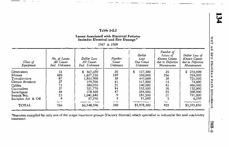
T a b l e 2 - 2 . 2
L o s s e s A s s o c i a t e d with Electrical Failures I n c l u d e s E l e c t r i c a l a n d F i r e D a m a g e *
1967 & 1968
Class of Equipment
3enerators Motors I'ransformers ~ircuit Breakers ~ables 3ontrollers 5witchgear ;witch Bds.
~witches Aii' & Oil
TOTAL
No. of Losses All Causes
Incl. Unknown
51 420
87 27 73 37 44 23
4
766
Dollar Loss All Causes
Incl. Unknown
$ 367,690 1,627,530 1,814,900
199,700 580,010 321,770 578,100
1,041,640 17,250
$6,548,590
Number Cause
Unknown
20 109
38 11 21 14 17
9 1
240
Dollar Loss
Due Cause Unknown
$ 117,300 560,000 445,000 117,000 140,000 152,500 254,000 181,500
11,000
$1,978,300
Number of Losses of
Known Causes due to Defective
Maintenance
25 256
38 14 45 18 23 11
3
433
Dollar Loss of Known Causes due to Defective
Maintenance
$ 233,000 924,000 721,000
74,600 406,000 132,000 308,000 791,000
6,250
$3,595,850
*Statistics compiled by only one of the major insurance groups (Factory Mutual) which specialize in industrial fire and machinery insurance.
5
t ~
o9
[

70B-10 ELECTRICAL EQUIPMENT MAINTENANCE
135
2-2.3 While benefits resulting from improved safety are difficult to measure; direct, measurable, economic benefits can be docu- mented by equipment repair cost and equipment downtime records after an EPM program has been placed in operation.
2-2.4 Dependability can be engineered and built into equip- ment, but effective maintenance is required to keep it that way. -Experience shows that equipment lasts longer and performs better when covered by an EPM program. In many cases, the investment in EPM is small compared to the cost of equipment repair and pro- duction losses associated with an unexpected equipment shutdown.
2-2.5 Careful planning is the key to economic success of an EPM program. With proper planning, maintenance costs will be held to a practical minimum, while production is maintained at a practical maximum.
2-2.6 Electrical preventive maintenance requires the support of top management , because it is top management who must provide funds to initiate ~and :maintain the program. Maintenance of in- dustrial electrical equipment is essentially a matter of business economics. Maintenance costs can be placed in either of two basic categories: (1) preventive maintenance; or (2) breakdown repairs. Money spent for preventive maintenance will be reflected as less money required for breakdown repairs. An effective EPM program holds the sum of these two expenditures to a minimum. Figure 2-3.1 is a typical curve illustrating this principle.
2-2.7 Electrical preventive maintenance is a form of protection against accidents, lost production and loss of profit. EPM enables management to place a dollar value on the..cost of such protection. .An effective EPM program satisfies an important part of manage- ment 's responsibility for .keeping costs down and production up.
2-2.8 Insurance statistics document the high cost of inadequate electrical maintenance (see Table 2-2.2). This table represents re- sults o f a study performed by only one of the major insurance groups (Factory Mutual) which specializes in industrial fire and machinery insurance~ The.table indicates that in a twd-year period (1967-68),
.one-half of the losses associated with .electrical equipment failures might have been prevented by ant-effective EPM program.
2-3 Case Histories: T h e y Gambled and Lost.
2-3.1 A ~total plant shutdown, resulted from the failure of a transformer in an industrial plant. Cause of the failure was con- tamination of the transformer insulating,oil. The "contamination

136 W H Y AN EPM P R O G R A M PAYS D I V I D E N D S 70B-11
z
\ .
' N , ~ ' ~ . L . J .
INTERVAL OF TIME BETWEEN EPM INSPECTIONS
i I COST OF EPM PLUC:.~ EQUIPMENT REPAIR . ' ~ AND REPLACEMENT "%N
i I
Fig. 2-3.1 Effect of EPM Inspection Frequency on Overall Costs
NOTE: As the interval of time between EPM inspections is increased, cost of EPM will diminish and cost of breakdown repairs and replace- ment of failed equipment will increase. The lowest total annual expense is realized by maintaining an inspection frequency that will keep the sum of repair/replacement and EPM costs at a minimuin.
went unde tec ted because the oil had not been tested for several years. Fi re d a m a g e and e q u i p m e n t r ep lacemen t costs a m o u n t e d to $50,000, exclusive of the cost of p lan t downt ime. This a m o u n t would have pa id for the cost of opera t ing an E P M p r o g r a m cov- er ing the ent i re p l an t e lectr ical d is t r ibut ion system for several years.
2-3.2 D a m a g e amoun t ing to $100,000 was a t t r ibu ted to the failure of the main swi tchgear in an indust r ia l plant . T h e failure was caused f rom fouling by dir t , g u m m y deposits, and iron filings. T h e cost of this fai lure would have suppor ted a comprehens ive E P M p r o g r a m cover ing all of the p lan t ' s e lectr ical d i s t r ibu t ion system for several years.
2-3.3 M c C o r m i c k Place, a large exhib i t ion hall in Chicago, was dest royed by a fire bel ieved to have been s tar ted because of a defective extension cord serving a d isp lay booth. Di rec t p rope r ty

70B-12 ELECTRICAL EQUIPMENT MAINTENANCE
137
loss was $60 million, and loss of the facility cost an additional $100 million to the economy in the Chicago area. This fire might have been prevented if a program had been in effect to ensure: that worn cords were replaced; that only heavy-duty cords were used; and that cords and their supply circuits were not overloaded.
2-3.4 Failure of a large motor shut down an entire industrial plant for 12 days. Cause of the failure was overheating resulting from dust-plugged cooling ducts. An EPM inspection would have detected the clogged ducts and averted the failure and accompany- ing plant outage.

138 WHAT IS AN E~'FECTIVE EPM PROGRAM? 70B-13
CHAPTER 3 -
WHAT IS AN EFFECTIVE EPM PROGRAM ?
3-1 General . An effective elcctrical preventive maintenance program is one which enhances safety and also reduces equipment failure to a minimum consistent with good economic judgment. Basic ingredients of such a program are men qualified to carry out the program, and regularly scheduled inspection, testing, and servicing of equipme,at. Equally important to the success of the program are (1) the application of sound judgment in evaluating and i,aterpreting results of inspections and tests, and (2) the keeping of concise, but complete records.
3-2 Planning an EPM Program. The following basic factors should be considered when planning an EPM program:
(a) Personnel Safety. Will an equipment failure endanger or threaten the safety of any personnel? What can be done to ensure personnel safety?
(b) Equipment Loss. Is installed equipment - - both electrical and mechanical - - complex or so unique that required repairs would be unusually expensive?
(c) Production Economics. Will breakdown repairs or replacement of failed equipment require extensive downtime? How many pro- duction dollars will be lost in event of an equipment failure? Which equipment is most vital to production?
3-3 Main Parts of an EPM Program.
3-3.1 Essential ingredients of an EPM program are:
(a) Responsible and qualified personnel.
(b) Survey and analysis of electrical equipment and systems to determine maintenance requirements and priorities.
(c) Programmed routine inspections and suitable tests.
(d) Accurate analysis of it~spection and test reports so that proper corrective measures can be prescribed.
(e) Performance of necessary work.
(f) Complete, but concise records.

70B-14 ELECTRICAL EQUIPMENT MAINTENANCE
139
3-3.2 A well-qualified individual should be in charge of the program. Men assigned to inspection and testing duties should be selected from the best maintenance men in the plant. Where in-plant personnel are not qualified, a maintenance contractor should be engaged.
3-3.3 Survey and analysis should cover equipment and systems that have been previously determined to be essential in accordance with a priority plan. Regardless of the size of the program being contemplated, the EPM supervisor must determine the extent of the work to be done and whe re t o begin. Therefore, all electrical equipment - - motors, trarisformers, circuit breakers, controls and the like - - should receive a thorough inspection and evaluation. Evaluating equipinent condition and the operating environment will permit the EPM supervisor to make a qualified judgment as to how, where, and when each piece of equipment should be fitted into the program.
3-3.4 In addition to determining physical condition, the survey should determine if the equipment is operating within its rating. In the course of the survey, it is imperative that the condition of electrical protective devices be checked. Such devices include fuses, circuit breakers, protective relays, and motor overload relays. These devices are the safety valves of an electrical system. They should be in proper operating condition to ensure safety of personnel, protection of equipment, and reduction of economic loss.
3-3.5 After the survey has been completed, data should be evalua- ated to determine equipment condition. Equipment condition will reveal repair work to be done, as well as the nature and fre- quency of required inspections and tests..
3-3.6 Inspection and testing procedures should be carefully tailored to requirements. In some plants, regularly scheduled tests will call for scheduled outages of production or process equip- ment. In such cases, close coordination is required between mainte- nance and production personnel.
3-3.7 Analysis of inspection and test reports should be followed by implementation of appropriate corrective measures. Follow- through with necessary repairs, replacement, and adjustment is in fact the end purpose of an effective EPM program.
3-3.8 Records should be accurate, and contain all vital informa- tion. Care should be taken to ensure that extraneous information does not become part of the record because excessive record keep- ing may hamper the program.

140 WHAT IS AN EFFECTIVE EPM PROGRAM? 70B-15
3-4 EPM Support Procedures.
3-4.1 Design for Ease of Maintenance. Effective electrical preventive maintenance begins with good design. In design of new facilities, conscious effort is required to ensurc optimum main- tainability. Dual circuits, tic circuits, auxiliary power sources, and drawout protective devices make it easier to schedule mainte- nance and to perform maintenance work with minimum interruption of production. Other effective design techniques include equip- ment rooms to provide environmental protection, grouping of equipment for more convenience and accessibility and standardiza- tion of cquipment and components.
3-4.2 Training for Technical Skills and Safety. Training pro- grams will help ensure continuing availability of qualified man- power. Instruction, both in and out of the plant, will provide a solid foundation in technical fundamentals and safe work procedures that are necessary to work on today's sophisticated equipmcnt.
3-4.3 Outside Service Agencies. Some maintenance and test- ing operations, such as relay and circuit breaker inspection and testing, require specialized skills and special equipment. In small organizations, it may be impractical to develop the skills and ac- quire the equipment needed for this type of work. In such cases, it might be advisable to contract the work to firms that specialize in providing such services.
3-4.4 Tools and Instruments. Proper tools and instxuments are an important part of an EPM program, and safety protective gear is an essential part of the necessary cquipmcnt. Proper tools, instruments, and other equipment will ensure maximum safety and productivity from the maintenance crew. Where specialized instruments and test equipment are needed only occasionally, they can be rented from a variety of sources.

70B-16 EI~ECTRICAL EQUIPMENT MAINTENANCE
141
CHAPTER 4 - PLANNING AND DEVELOPING A N ELECTRICAL PREVENTIVE MAINTENANCE
PROGRAM
4-1 Introduction.
4-1.1 The purpose of an EPM program is to reduce hazard to life and property that can result from failure or malfunction of in- dustrial type electrical systems and cquipment. The first part of these recommendations for an effective electrical preventive mainte- nance (EPM) program has been prepared with the intent of pro- viding a better understanding of benefits - - both direct and in- tangible - - that can be derived from a well-administered EPM program. This chapter explains the function, requirements, and economic considerations that can be used to establish such a program.
4-1.2 There are four basic steps to be taken in the planning and development of an electrical preventive maintenance program. In their simplest form, they are:
(a) Compile a listing of all plant equipment and systems.
(b) Determine what equipment and/or systems are most critical and most important.
(c) Develop a system for keeping up with what needs to be done.
(d) Train people for the work that needs to be done, or contract for the special services that are needed.
4-1.3 Success of an.EP2vL program is dependent on the caliber of personnel responsible for its implementation. Primary responsi- bility for program implementation and its success should lie with a single individual. This individual should be given the authority to-do the job and he should have the cooperation of management, production, and other departments whose operations might affect the EPM program. Ideally, the person designated to head the EPM program should have the following qualifications:
(a) Technical Competence. He should, by education, training and experience, be well-rounded in all aspects of electrical maintenance.
"(b) Administrative and Supervisory Skills. He should be skilled in planning, development of long-range objectives to achieve specific results, and should be able to command respect and solicit the cooperation of all persons involved in the program.

142 P L A N N I N G A N D D E V E L O P I N G A N E P M P R O G R A M 70B-17
4-1.4 The maintenance supervisor should have open lines of communication with design supervision. Frequently an unsafe in- stallation or one requiring excessive maintenance can be traced to improper design or construction methods or misapplication of hardware.
4-1.5 The work center of each maintenance work group, whether it be a zone or total plant, should be conveniently located. This work center should contain all of the inspection and testing procedures for that zone, copies of previous reports, single-line diagrams, schematic diagrams, record of complete nameplate data, vendors' catalogs, plant stores catalogs, and supplies of report forms. There should be adequate storage facilities for the tools and test equipment that are common to the group.
4-1.6 In a continuously operating plant, running inspections (inspections made with equipment operating)play a very vital role in the continuity of service. The development of running inspec- tion procedures varies with the type of operation. However, they should be as thorough as practicable within the limits of safety and the skill of the craftsman. These procedures should be reviewed regularly in order to keep them current. Each failure of electrical equipment, be it an electrical or mechanical failure, should be reviewed against the running inspection procedure to determine if some other inspection technique would have indicated the im- pending failure. I f so, the procedure should be modified to reflect the findings.
4-1.7 Handling the results of running inspections is the area that gives supervisors their best motivational opportunities. When the electrical maintenance supervisor initiates corrective action the craftsman should be so informed; the craftsman who found the condition will then feel that his job was worthwhile and will be motivated to try even harder. However, if nothing is done, indi- vidual motivation may be adversely affected.
4-1.8 Trends in failure rates are hard to change and take a long time to reverse. For this .reason, the inspection should con- tinue and resulting work orders written, even though the work force may have been reduced. Using the backlog of work orders as an indicator, the electrical maintenance supervisor can predict trends before they develop. With the accumulation of a sizable backlog of work orders, an increase of electrical failures and production downtime may be expected.
4-2 Survey of Electrical Installation.

70B-18 :ELECTRICAL EQUIPMENT MAINTENANCE
143
4-2.1 Definition. The survey may be defined as the collection of accurate data on the plant electrical system and the evaluation of this data to obtain the necessary information for developing the EPM program. The systems and equipment covered in specific parts of the survey should be based on logical divisions of the over- all plant, either on an electrical system or plant process basis. In some cases a combination of the two is the most suitable.
4-2.2 Data Collection.
4-2.2.1 The first step in organizing a survey is to take a look at the total "package." Will the available manpower permit the survey of an entire system, process or building, or must it be divided into segments?
4-2.2.2 Next, a priority should be assigned to each segment. Some segments may be found to be sequential, so they should be identified before the actual work commences.
4-2.2.3 The third step is the assembling of all documenta-. tion. This may necessitate a search of desks, cabinets, etc., in the plant area, and may also requirc that malmfacturers bc contacted in order to replace lost documents. All of these documents should be brought to a central location and marked immediately with some form of effective identification.
4-2.3 Diagrams and Data.
4-2.3.1 The availability of up-to-date, accurate, and com- plete diagrams is the foundation of a successful EPM program. No EPM program can operate without them, and their importance cannot be overemphasized. The following diagrams are some of those in common use:
4-2.3.2 Single-line diagrams trace the flow of electrical power. They should show all electrical equipment in the. system and give all pertinent ratings. In making this type of diagram it is basic that voltage, frequency, phase, and normal operating position should be included. No less important, but perhaps less obvious, are items such as transformer impedance, available short- circuit current, and equipment continuous and interrupting ratings. Other items include current and potential transformers and their ratios, surge capacitors, and protective relays. Where one diagram cannot cover all of the equipment involved, additional diagrams, appropriately noted on the main diagram, should be drawn.
4-2.3.3 Short-circuit and coordination study is very im- portant. Many have the misconception that this engineering study is part of the initial plant design, after which the subject can be

144 P L A N N I N G A N D D E V E L O P I N G A N E P M P R O G R A M 70B-19
forgotten. However, a number of factors can affect the available short-circuit current in an electrical system. Among these are changes in the supply capacity of the utility company, changes in size or percent impedance of transformers, changes in conductor size, addition of motors, and system operating conditions.
4-2.3.3.1 In the course of periodic maintenance testing of protective eqmpment" i such as relays and series or shunt-trip devices, their settings should be evaluated. Along with the proper sizing of fuses this is part of the coordination study.
4-2.3.3.2 In a small plant - - one receiving electrical energy at utilization voltage, or from a single step-down transformer - - the short-circuit study is very simple. The available incoming short-circuit current can be obtained from the utility company sales engineer.
4-2.3.3.3 In a larger system, it may be desirable to de- velop a computerized short-circuit study to improve accuracy and reduce engineering time. Should facilities not be available within the plant organization, the short-circuit study can be performed on a contract basis. The short-circuit data are used to determine the required momentary and interrupting ratings of circuit breakers, fuses and other equipment.
4-2.3.3.4 Fuses are rated on the basis of their current- carrying and interrupting capacities. These ratings should be de- termined and recorded. Other protective devices are usually ad- justable as to pickup point and time-current characteristics. Set- tings of such protective devices should be determined, verified by electrical tests, and recorded for future reference.
4-2.3.3.5 Personnel performing the tests should be trained in proper test procedures. Several manufacturers of switchgear or test equipment have set up regularly scheduled seminars where participants are taught the principles of maintenance and testing of electrical protective devices.
4-2.3.4 Circuit routing diagrams, cable maps, or raceway layouts show the physical location of conductor runs. In addition to voltage, such diagrams should also indicate the type of raceway, the number and size of conductors, and type of insulation. Where control conductors or conductors of different systems are contained within the same raceway, the coding appropriate to each con- ductor should be noted. Vertical and horizontal runs, with the location of taps, headers and pull boxes, should be shown. Access points should be noted where raceways pass through tunnels or shafts with limited access.

70B-20 ' E L E C T R I C A L E Q U I P M E N T M A I N T E N A N C E
145
4-2.3.5 Layout diagrams, plot plans, equipment location plans, or plant maps show the physical layout (and in some cases, the elevations) of the plant with all equipment in place. Switching equipment, transformers, control panels, mains, and feeders should be identified. Voltage and current ratings should be shown for each piece of equipment.
4-2.3.6 Schematic diagrams are arranged for simplicity and ease of understanding circuits without regard for the actual physical location of any components. The schematic is always drawn with switches and contacts shown in a de-energized position.
4-2.3.7 Wiring diagrams, like schematics, should show all components in the circuit, but they are arranged in their actual physical location. Electro-mechanical components and strictly me- chanical components interacting with electrical components are shown. Of particular value is the designation of terminals and terminal strips with their appropriate numbers, letters, and/or colors.
4-2.3.8 Diagrams should identify all equipment parts and devices by standard methods, symbols, and markings.
4-2.4 System Diagrams.
4-2.4.1 System diagrams generally are needed to complete the data being assembled. The importance of the system deter- mines the extent of information shown, or for a small plant, whether it is even needed. The information may be shown on the most appropriate type of diagram, but should include the same basic information, source and type of power, conductor and raceway in- formation, and switching and protective devices with their physical locations. It is vital to show where the system may interface with another, such as with emergency power; hydraulic, pneumatic, or mechanical systems; security and fire alarm systems; and monitor- ing and control systems. Some of the more common of these are described in subsections 4-2.4.1 through 4-2.4.5.
4-2.4.2 Lighting system diagrams (normal and emergency) may terminate at the branch-circuit panelboard, listing the num- ber of fixtures, type and lamp size for each area, and the design lighting level. It should show watchman lights and probably an automatic transfer switch to the emergency power system.
4-2.4.3 Ventilation systems normally comprise the heating, cooling, and air-filtering system. Exceptions include furnace, dryer, oven, casting, and similar areas where process heat is ex- cessive and air conditioning is not practical. Numerous fans are used to exhaust the heated and possibly foul air. In.some industries,

146 P L A N N I N G AND D E V E L O P I N G AN EPM PROGRAM 70B-21
such as chemical plants and those using large amounts of flam- mable solvents, large volumes of air are needed to remove the haz- ardous vapors. Basic information, including motor and fan sizes, motor or pneumatically operated dampers, etc., should be shown. Additionally, many safety features may be involved to ensure starting of fans before the process - - airflow switches to shut down an operation on loss of ventilation - - and other interlocks of similar nature. Each of these should be identified with respect to type, function, physical location, and its operating limits.
4-2.4.4 Heating and air conditioning systems are usually manufactured and installed as a unit - - furnished with diagrams, operating and maintenance manuals. This information should be updated as the system may be changed or modified. Because these systems are often critical to plant operation, additional equipment may have been incorporated - - humidity, lint, and dust control for textile, electronic, and similar processes; corrosive and flam- mable vapor control for chemical and related industries, etc. In- variably these interface with other electrical or nonelectrical sys- tems: pneumatic, or electro-mechanical operation of da.mpers, valves, etc.; electric operation for normal and abnormal tempera- ture control; manual control stations for emergency smoke re- moval, are just a few. There may be others, but all should be shown and complete information given for each.
4-2.4.5 Control and monitoring system diagrams are neces- sary to understand how these complicated systems function. They usually are in the form of a schematic diagram and may refer to specific wiring diagrams. Max imum benefit can only be obtained when every switching device is shown, its function indicated, and identified for ease in finding a replacement. These often involve interfaces with other systems, whether electro-mechanical (heating or cooling medium) pumps and valves; electro-pneumatic tempera- ture and damper control; safety and emergency operations. A sequence-of-operation chart and list of safety precautions should be included to promote safety of personnel and equipment. Under- standing these complex circuits is best accomplished by breaking down the circuits into their natural functions, such as heating, cooling, process, or humidity controls. The knowledge of how each function relates to another enables the craftsman to have a better concept of the entire system and thus perform his assignment more efficiently.
4-2.5 Emergency Procedures . Emergency procedures should list, step by step, the action to be taken in case of emergency, or for the safe shutdown or start-up of equipment or systems. Opti- mum use of these pr6cedures is made when they are bound for

70B-22 ELECTRICAL EQUIPMENT MAINTENANCE
147
quick reference and posted in the area of the equipment or systems. Some possible items to consider for inclusion in the emergency procedures are interlock types and locations, interconnections with other systems, and tagging procedures of the equipment or systems. Accurate single-line diagrams posted in strategic places are par- ticularly helpful in emergency situations. The production of such diagrams in anticipation of an emergency is essential to a complete EPM program. Diagrams are a particularly important training tool in developing a state of preparedness. Complete and up-to- date diagrams provide quick review of emergency plan. During an actual emergency they provide a simple, quick-reference guide when time is at a premium.
4-2.6 Test and Maintenance Equipment.
4-2.6.1 All maintenance work requires the use of proper tools and equipment to properly perform the task to be done. In addition to their ordinary tools, each craftsman (such as car- penters, pipe fitters, and machinists) uses some special tools or equipment based on the nature of the work to be performed. The electrician is no exception, but for EPM, additional equipment not found in his toolbox should be readily available. The size of the plant; nature of its operations; extent of its maintenance, repair, and test facilities; are all factors which determine the use-frequency of the equipment. Economics seldom justify purchasing an in- frequently used expensive tool when it can be rented. However, a corporation having a number of plants in the area may well justify common ownership of the same device for joint use, making it quickly available at any time to any plant. Typical examples might be high-current or DC high-potential test equipment, or a ground-fault locator.
4-2.6.2 A certain amount of mechanical maintenance is often a part of the EPM program being conducted on associated equipment. The electrical craftsman should have ready access to such items as assorted lubrication tools and equipment; various types and sizes of wrenches; nonmetallic hammers and blocks to protect against injury to machined sin faces; wheel pullers; feeler gages; inside- and outside-diameter measuring gages; instru- ments for measuring torque, tension, compression, vibration, and speed; standard and special mirrors with light sources for visual inspection; portable blowers and vacuums of industrial type having insulated nozzles for removal of dust and foreign matter; nontoziic, nonflammable cleaning solvents; and clean lint-free wiping cloths.
4-2.6.3 The use of well-maintained safety equipment is essential and should be mandatory when working on or near live electrical equipment. Some of the more important articles needed

148 P L A N N I N G A N D D E V E L O P I N G A N E P M P R O G R A M 70B-23
are heavy leather gloves; insulating gloves, mats, blankets, baskets, boots, jackets and coats; insulated hand tools such as screw drivers and pliers; nonmetallic hard hats with clear insulating face shields for protection against arcs; poles with hooks and hot sticks to safely open isolating switches. A statiscope is desirable to indicate the presence of high voltage on certain types of equipment.
4-2.6.4 Portable electric lighting is often necessary par- ticularly in emergencies involving the plant power supply. Portable electric lighting used for maintenance areas which are normally wet or where personnel will be working within grounded metal structures such as drums, tanks, and vessels should be operated at a maxinmm of 12 volts supplied from an isolating transformer or other isolated source. Ample supply of battery lanterns should be available with extra batteries. Suitable extension cords are usually necessary.
4-2.6.5 Portable meters and instruments are necessary for testing and troubleshooting, especially on circuits of 600 volts or less: These include general-purpose volt meters, volt-ohmmeters, and clip-on-type ammeters with multiscale ranges. In addition to these conventional instruments, recording meters are useful for measuring magnitudes and fluctuations of current, voltage, power factor, watts and volt-amperes versus time values. These are a definite aid in defining specific electrical problems and to determine if equipment malfunction is due to abnormal electrical conditions. Other valuable test equipment includes devices to measure insula- tion resistance of motors and similar equipment in the megohm range and similar instruments in the low range for determining ground resistance, lightning protection systems, and grounding systems. Continuity testers are particularly valuable for checking control circuits and for circuit identification.
4-2.6.6 A ground-loop tester is an important part of the EPM equipment. I t is used to check the continuity of the equip- ment grounding circuit regardless of its location, including the grounding slot of receptacles. I t can also be used to check the equipment grounding circuit of portable electric tools.
4-2.6.7 Insulation-resistance measuring equipment should be used to indicate insulation values at the time equipment is put in service. Later measurements may indicate any deterioration trend of the insulation values of the equipment. High-potential AC and DC testers are used effectively to indicate dielectric strength and insulation resistance of the insulation respectively. I t should be recognized that the possibility of breakdown under test due to concealed weakness is always present. High-potential testing should be performed with caution and only by qualified operators.

70B-24 ELECTRICAL EQUIPMENT MAINTENANCE
149
4-2.6.8 Portable ground-fault locators can be used to test ungrounded power systems. Such devices will indicate ground location while the power system is energized. They are thus a valuable aid for safe operation by indicating where to take cor- rective steps before an insulation breakdown occurs on another phase.
4-3 Identification of Critical Equipment.
4-3.1 Equipment (electrical or otherwise) is considered critical if its failure to operate normally and under complete control will cause a serious threat to people, property, or the product. Electric power, like process steam, water, etc., may be essential to the op- eration of a machine, but unless loss of one or more of these sup- plies causes: the machine to become hazardous to people, property or production, that machine may not be critical. The combined knowledge and experience of several people may be needed to make this determination. In a small plant this can probably be done by the plant engineer or master mechanic working with the operating superintendent. A large operation may need a " team" corot)rising the following qualified people: (1) the electrical fore- man or superintendent; (2) a production man or men thoroughly familiar with the operation capabilities of the equipment and the effect its loss will have on final production; (3) the senior mainte- nance man who is generally familiar with the maintenance and repair history of the equipment or process; (4) a technical man knowledgeable in the theoretical fundaincntals of the process and its hazards (in a chemical plant he should be a chemist, in a mine a geologist, etc); and (5) a safety engineer or one responsible for the overall security of the plant and its people against fire and accidents of all kinds. They should go over the entire plant or each of its operating segments in detail, considering each unit of equipment as related to the entire operation, and the effect of its loss on safety and production.
4-3.2 There are entire systems that may be critical by their very nature. Depending on the size of the plant and the complexity of the operation, it may contain any or all of the examples listed: emergency power, emergency lighting, fire alarm systems, fire pumps, and certain connnunication systems. There should be no problem in establishing whether or not any of these systems is critical, and in having the proper a,nount of emphasis placed on its maintenance.
4-3.3 More difficult to identify are the parts of a system which are critical because of the function of the utilization equip- ment and its associated hardware. Some examples are:

150 PLANNING AND D E V E L O P I N G AN EPM PROGRAM 70B-25
(a) The agitator drive motor for a kettle-type reactor may be extremely critical in that, if it fails to run for some period of time, when the charge materials are added to the reactor the catalyst stratifies. I f the motor is then started, rather than a slow, controlled reaction, a rapid reaction could result that may run away, over- pressurize, and destroy the reactor.
(b) The cooling water source of an exothermic reactor may have associated with it some electrical equipment such as a drive motor, solenoid valves, controls or the like. The failure of this cool- ing water may allow the exothermic reaction to go beyond the stable point and overpressurize and destroy the vessel.
(c) A process furnace recirculating fan drive motor or fan may fail, nullifying the effects of temperature sensing points allow- ing hot spots to develop with serious side reaction.
(d) The failure of gas analysis equipment and interlocks in a drying oven or annealing furnace may allow the a tmosphere in • the drying oven or furnace to become f lammable with the possibility of an explosion.
(e) The failure of any of the safety combust ion controls on a large fire box, such as a boiler or incinerator, may cause a serious explosion.
(f) T w o paralleled p u m p motors may be needed to provide the total requirements of a continuous process. Failure of either of these motors may cause a complete shutdown, rather than simply reduce production.
4-3.4 There are parts of the system that are critical because they reduce the widespread effect of a fault in electrical equipment. The determinat ion of these is primarily the responsibility of the electrical man on the team. Among the things that fall in this category are :
(a) Some overcurrent protective devices, such as circuit breakers or fuses. This includes the relays and control circuits. I t also includes the coordinat ion of trip characteristics of the devices.
(b) Automat ic bus transfer switches or other transfer switches that would supply critical loads with power from the emergency power source if the pr imary source failed. This includes instru- ment power supplies as well as load power supplies.
4-3.5 Parts of the control system are critical because they moni- tor the process and automatical ly shut down equipment or take other action to prevent catastrophe. These items are the interlocks, cut- out devices, or shutdown devices installed throughout the plant or

70B-26 ELECTRICAL EQUIPMENT MAINTENANCE
151
operation. Each of these interlocks or shutdown devices should be carefully considered by the entire team to establish whether or not they are critical shutdowns or whether they are "convenience" shutdowns. I t should be thoroughly understood by the maintenance group which shutdowns are critical and which are convenience. The critical shutdown devices are normally characterized by having a sensing device separate from the normal control device. I t prob- ably has a separate, final, or end device that causes action to take place. Once the critical shutdown systems are recognized, they should be distinctly identified on drawings, on records, and on the hardware itself. Some examples of critical shutdown devices are: overspeed trips, high or low temperature, pressure, flow or level trips, low lube oil pressure trips, pressure relief valves, overcurrent trips, and low-voltage trips.
4-3.6 There are parts of the system that are critical because they alert operating personnel to dangerous or out-of-control conditions. These are normally referred to as alarms. Like shut- down devices, alarms fall into at least three categories: (1) those that signify a true pending catastrophe; (2) those that indicate out-of-control conditions; and (3) those that indicate the end of an operation or similar condition. The entire team should con- sider each alarm in t h e system with the same thoroughness with which they have considered the shutdown circuits. The truly critical alarm should be characterized by having a separate sensing device, a separate readout device, and preferably separate cir- cuitry and power source. The maintenance department should thoroughly understand the critical level of each of the alarms. The critical alarms and the significance should be distinctly marked on drawings, in records, and on the operating unit. For an alarm to be critical does not necessarily mean that it is complex or re- lated to complex action. A simple valve position indicator may be one of the most critical alarms in an operating unit.
4-4 Establishment of a Systematic Program.
4-4.1 The purpose of any inspection and testing program is to establish the condition of equipment to determine what work should be done and to verify that it will continue to function until the next scheduled servicing occurs. Inspection and testing is best done in conjunction with routine maintenance. In this way, many minor items that require no special tools, training, or equip- ment can be corrected as they are found. The inspection and testing program is probably the most important function of a maintenance department in that it establishes what needs to be done to keep the system in service to pe r fo rm the function for which it is required.

152 P L A N N I N G AND D E V E L O P I N G AN EPM PROGRAM 70B-27
4-4.2 Atmosphere or Environment . ,,
4-4.2.1 The atmosphere or environment in which electrical ~ equipment is located has a definite effect on its operating capabilities ~ and the degree of maintenance required. An ideal environment is one in which the air is: (1) clean or filtered to remove dust, harmful vapor, excess moisture, etc.; (2) the temperature is maintained in the range of 60°F to 85°F; and, (3) the humidity in the range of 40-70 percent. Under such conditions the need for maintenance will be minimized. Where these conditions are not maintained, the performance of electrical equipment will be adversely affected. Good housekeeping contributes to a good environment and reduced maintenance.
4-4.2.2 Dust can foul cooling passages and thusreduce the ca- pabilities of motors, transformers, switchgear, etc., by raising their operating temperatures above rated limits, decreasing operating ef- ficiencies, and increasing fire hazard. Similarly, chemicals and vapors can coat and reduce the heat transfer capabilities of heating and cooling equipment. Chemicals, dusts, and vapors can be highly flammable, explosive, or conductive, increasing the hazard of fire, explosion, ground, faults, and short circuits. Chemicals and cor- rosive vapors can cause high contact resistance, which will de- crease contact life and increase contact power losses with possible fire hazard or false overload conditions due to excess heat. Large temperature changes combined with high humidity can cause con- densation problems, malfunction of operating and safety devices, and lubrication problems. High ambient temperatures in areas where thermally sensitive protective equipment is located can cause such protective equipment to operate below its intended op- erating point. Ideally, both the electrical apparatus and its pro- tective equipment should be located within the same ambient. Where the ambient temperature difference between equipment and its protective device is extreme, compensation in the pro- tective equipment should be made.
4-4.3 Load Conditions.
4-4.3.1 Equipment is designed and rated to perform satisfac- torily when subjected to specific operating and load conditions. A motor designed for safe continuous operation at rated load may not be satisfactory for frequent intermittent operation, which can pro- duce excessive winding temperatures or mechanical trouble. The re- sistance grid or transformer of a reduced-voltage starter will over- heat if left in the starting position. So-called "jogging" or "inching" service imposes severe demands on equipment such as motors, starters, and controls. Each type of duty influences the type of

70B-28 ELECTRICAL EQUIPMENT MAINTENANCE
153
equipment used and ~the extent of maintenance required. The five most common types of duty are defined in the National Electrical Code, and they are repeated in subsection 4-4.3.2 below.
4-4.3.2 Duty is defined as:
C O N T I N U O U S : Operation at a substantially constant load for an indefinitely long time.
I N T E R M I T T E N T : Operation for alternate intervals of (1) load and no load; (2) load and rest; (3) load, no load, and rest.
PERIODIC: Intermittent operation in which the load conditions are regularly recurrent.
SHORT-TIME." Operation at a substantially constant load for a short and definitely specified time.
VARYING." Operation at loads, and for intervals of time, both of which may be subject to wide variation.
4-4.3.3 Some devices that may be of use in establishing a proper maintenance period are: running time meters (to measure total "on" or "use" time); counters to measure number of starts, stops or load on, load off and rest periods; and recording ammeters to record graphically load and no-load conditions. These devices can be applied to any system or equipment and will help classify the duty. This will help establish a proper frequency of preventive maintenance.
4-4.3.4 Safety and limit controls are devices whose sole function is to assure that values remain within the safe design level of the system. Each device should be periodically and carefully in- spected, checked, and tested to be certain that it is in reliable op- erating condition because it fun.ctions only during an abnormal situation when an undesirable or unsafe condition is reached.
4-4.4 Wherever practical, a history of each electrical system should be developed for all equipment or parts of a system vital to a plant's operation, production or process. The record should include all pertinent information for proper operation and mainte- nance. This information is useful in developing repair cost trends, items replaced, design changes or modifications, significant trouble or failure patterns, and replacement parts or devices that should be stocked. System and equipment information should include:
(a) Types of electrical equipment - - motors, starters, con- tactors, heaters, relays.
(b) Types of mechanical equipment - - valves, controls, etc., and driven equipment such as pumps, compressors, fans - - and whether they are direct, geared, or belt driven.

.154 P L A N N I N G A N D D E V E L O P I N G A N E P M P R O G R A M 70B-29
(c) Nameplate data.
(d) Equipment use.
(e) Installation date.
(f) Available replacement parts.
(g) Maintenance test and inspection date - - type and fre- quency of lubrication; electrical inspections, test, and repair; me- chanical inspection, test, and repair; replacement parts list with manufacturer 's identification; electrical and mechanical drawings for assembly, repair and operation.
• 4-4.5 I n s p e c t i o n F r e q u e n c y .
4-4.5.I Those pieces of equipment found to be critical should require the most frequent inspections and tests. Depending on the degree of reliability required, other items may be inspected and tested nmch less frequently.
4-4.5.2 Manufacturers ' service manuals should have a recommended frequency of inspection. The frequency given is based on "s tandard" or "usual" operating conditions and environ- ments. I t would be impossible for the manufacturer to list all com- binations of environment and operating conditions. However, this is a good basis from which to begin considering the frequency for inspection and testing.
4-4.5.3 There are several points to consider in establishing the initial frequency of inspections and tests. Electrical equipment located in a separate air-conditioned control room or switch room certainly would not be considered normal, so the inspection in- terval might be extended 30 percent. However, if the equip- ment is located near another unit or operating plant that discharges dust or corrosive vapors, it might reduce this time as much as 50 percent.
4-4-5.4 Continuously operating units with steady loads or with less than the rated full load would tend to operate much longer, and more reliably, than intermittently operated or standby units. For this reason, the interval between inspections might be ex- tended I0 to 20 percent, for continuously operating equipment and possibly reduced by 20 to 40 percent for standby or infre- quently operated equipment.
4-4.5.5 Once the initial frequency for inspection and tests has been established, this frequency should be adhered to for at least four maintenance cycles unless undue failures occur. For equip-
70B-30, ELECTRICAL EQUIPMENT MAINTENANCE 155
ment that has unexpected failures, the interval between inspections should be reduced by 50 percent as soon as the trouble occurs. On the other hand, after four cycles of inspections have been com- pleted, a pattern should have developed. I f equipment consistently goes th rough more than two inspections without requiring service, the inspection period may be extended by 50 percent. Loss of pro- duction due to an emergency shutdown is almost always more ex- pensive than loss of production due to a planned shutdown. Ac- cordingly, the interval between inspections should be planned to avoid the diminishing returns of either too long or too short an interval.
4-4.5.6 This adjustment in the interval between inspections will continue until the opt imum interval is reached. This adjustment time c a n be minimized and the opt imum interval approximated more closely initially by providing the person responsible for establishing the first interval with as nmch pertinent history and technology as possible.
4-4.5.7 The frequency of inspection for similar equipment op- erating under different conditions may need to be widely different.
Typical examples illustrating this are:
(a) In a continuously operating plant having a good load factor and located in a favorable environment, the high-voltage oil circuit breakers may only need an inspection every two years. On the other hand, an electrolytic process plant using similar oil circuit breakers for controlling furnaces may find it necessary to inspect and service them as frequently as every 7 to 10 days.
(b) An emergency generator to provide power for noncritical loads may be tested on a monthly basis. Yet the same generator in another plant having processes sensitive to explosion on loss of power may need to be tested each shift.
4-5 Methods and Procedures .
4-5.1 General .
4-5.1.1 I f a system is to operate without failure, not only should the discrete components of the system be maintained, but the connections between these components should also be covered by a thorough set of methods and procedures. Overlooking this important link in the system causes many companies to suffer high losses every year.
4-5.1.2 Other areas where the maintenance department should develop their own procedures are shutdown safeguards,

156 P L A N N I N G AND D E V E L O P I N G AN EPM PROGRAM .70B-31
interlocks, and alarms. Although the individual pieces of equipment may have testing and calibrating procedures fur- nished by the manufacturer, the application is probably unique, so that the system, per se, should have an inspection and testing pro- cedure developed for it.
4-5.2 Forms.
4-5.2.1 A variety of forms may go along with the inspection, testing, and repair (I T & R) procedure. They should be detailed and direct, yet simple and durable enough to be used in the field. Field notes taken should be legibly transcribed. One copy of re- ports should go in the working file of the piece of equipment and one in the master file maintained by first line supervision. These forms should be used by the electrical maintenance people. They are not for general distribution. If reports to production or engi- neering are needed, they should be separate, and inspection reports should not be used.
4-5.2.2 The I T & R procedure folder for a piece of equip- ment should have listed in it:
(a) All the special tools, materials, and equipment neces- sary to do the job.
(b) The estimated or actual average time to do the job.
(c) Appropriate references to technical manuals.
(d) Previous work done on the equipment.
(e) Points for special attention indicated by previous I T & R. If major work was predicted at the last I T & R, the pro-
cedure folder should contain a copy of the purchase order and re- ceiving reports for the parts to do the work. I t should contain ref- erences to unusual incidents reported by production that may be associated with the equipment.
4-5.2.3 Special precautions relative to operation should be part of the I T & R document. What other equipment is affected and in what way? Who has to be informed that the I T & R i s going to be done? How long will the equipment be out of service if all goes well and also if major problems are uncovered?
4-5.3 Planning.
4-5.3.1 Having developed the I T & K procedures and having the frequency established (even though preliminary) now comes the task of scheduling. Scheduling in a continuous process plant (as opposed to a batch-process plant) is most critically affected by availability of equipment in blocks consistent with maintenance

70B-32 ELECTRICAL EQUIPMENT MAINTENANCE
157
~, manpower capabilities. In general, plants will be shut down on some -'Jregular basis for overall maintenance and repair. Some of the o;electrical maintenance items should be done at this time. I T & R
that could be done while equipment is in service should be done prior to shutdown. Only work that need be done during shutdown should be scheduled at that time - - to level out manpower re- quirements and to limit downtime.
4-5.3.2 The very exercise of scheduling I T & R will point out design weaknesses that require excessive manpower during
'critical shutdown periods or require excessive downtime to do the job with the men available. Once these weaknesses have been un- covered, consideration can be given to rectifying them. For ex- ample, the addition of one circuit breaker and a little cable may change a shutdown from three days to one day.
4-5.3.3 Availability of spare equipment affects scheduling in many ways. Older plants may have installed spares for a major part of the equipment, or the plant may be made up of many parallel lines so that they may be shut down, one at a time, with- out seriously curtailing production. This concept is particularly adaptable to electrical distribution. Use of a circuit breaker and a transfer bus may extend the interval between total shutdown on a main transformer station from once a year to once in 5 years or more.
4-5.3.4 In many continuous process plants, particularly the newer ones, the trend is toward a large single-process line with no installed spares. This method of operation will require running inspections and running tests since there will be a natural desire to extend the time between maintenance shutdowns. Downtime in such plants will be particularly costly, so it is desirable to build as much monitoring into the electrical systems as possible.
4-5.3.5 Planning" running inspections can vary from a simple desk calendar to a computer program. Any program for scheduling should have four facets: (1) a reminder to order parts and equipment with sufficient lead time to have them on the job when needed; (2) the date and man-hours to do the job; (3) a check to see that the job has been completed; and (4) noticing if parts are needed for the next I T & R and when they should be ordered.
4-5.3.6 Planning shutdown I T & R is governed by the time between shutdowns established by the limitations of the process or production units involved. Reliability of electrical equipment can and should be built in to correspond to almost any length of time.

158 P L A N N I N G A N D D E V E L O P I N G A N E P M P R O G R A M 70B-33
4-5.3.7 Small plants will want to utilize, in a much abbrevi- ated form, the following shutdown recommendations of a large p l a n t I T & R:
(a) Know how many man-shifts the work will take.
(b) Know how many men will be available.
(c) Inform production how many shifts the electrical mainte- nance will require.
(d) Have all the tools, materials, and spare parts that will be required assembled on the job site. Overage is better than shortage.
(e) Plan the work so that each man is used to best suit his skills.
(f) Plan what each man will be doing each hour of the shutdown. Allow sufficient off time so that if a job is not finished as scheduled, the men working on that job can be held over with- out overtiring them for the next shift. This will allow the schedule to be kept.
(g) Additional clerical people during shutdown I T & R will make the job go smoother; help prevent missing some impor- tant function, and allow an easier transition back to notarial..
(h) Supply copies of the electrical group plan to the over- all shutdown coordinator so that it can be incorporated into the overall plan. The overall plan should be presented in a form that. is easy to use by all levels of supervision. In a large complex op- eration, a critical path program, or some similar program, should be used.
4-5.3.8 Automatic shutdown systems and alarm systems that have been determined as critical should be so designed and maintained that nuisance tripping does not destroy operator confi- dence. Loss of operator confidence can and will cause these systems to be bypassed and the intended safety lost. Maintenance should prove that each operation was valid and caused by an unsafe con- dition.
4-5.3.9 A good electrical preventive maintenance program should identify the less critical jobs, so it will be clear to first-line supervision which EPM can be delayed, to make men available for emergency breakdown repair.
4-5.4 Analysis of Safety Procedures.
4-5.4.1 I t is beyond the scope of this recommended prac- tice to cover details of safety procedures for each of the I T & R activities. Manufacturers' instructions contain safety procedures required in using their test equipment.

70B-34 ELECTRICAL EQUIPMENT MAINTENANCE
159
4-5.4.2 The test equipment (high voltage, high current, or other uses) should be inspected in accordance with vendor recom- mendations before the job is started. Any unsafe condition should be corrected before proceeding.
4-5.4.3 The people doing the I T & R should be briefed to be sure that all facets of safety before, during, and after the I T & R are understood. I t is important that all protective e q u i p - ment is in good condition and is on the job..
4-5.4.4 Screens, ropes, guards, and signs needed to protect people other than the I T & R team should be provided and used.
4-5.4.5 A procedure should be developed, understood, and used for leaving the test site in a safe condition when unattended. These times may include a smoke break, a lunch break, or even overnight.
4-5.4.6 A procedure should be developed, understood, and used to ensure safety to and from the process before, during, and after the I T & R. The process or other operation should be put in a safe condition for the I T & R by the operating people before the work is started. The procedure should include such checks as are necessary to ensure that the unit is ready for operation after the I T & R is completed and before the operation is restarted.
4-5.5 Records.~
4-5.5.1 Sufficient records should be kept by maintenance management to evaluate results. Analysis of the records should guide the spending level for EPM and breakdown repair.
4-5.5.2 Figures should be kept to show the total cost of each breakdown. This should be the actual cost plus an estimated cost of the business interruption. This figure is a powerful indi- cator for the guidance of expenditures for EPM.
4-5.5.3 Records Kept by First Line Supervisor of EPM. Of the many approaches to this phase of the program, the following is a typical set that fulfills the minimum requirements:
(a) Inspection Schedule. The first line supervisor should main- tain, in some easy to use form, a schedule of inspections so that he can plan manpower requirements.
(b) Work Order Log. An active log should be kept of un- finished work orders. A greater susceptibility to imminent break- down is indicated by a large number of outstanding work orders resulting from the inspection function.

160 P L A N N I N G A N D ' D E V E L O P I N G A N E P M P R O G R A M 70B-35
(c) Unusual Event Log. As the name implies, this lists un- usual events that affect the electrical system in any way. This record is derived from reports of operating and other personnel. This is a good tool for finding likely problems after the supervisor has learned to interpret and evaluate the reports he gets. This is the place where near misses can be recorded and credit given for averting trouble.
4-5.6. E m e r g e n c y Procedures . I t should be recognized that properly trained electrical maintenance personnel have the po- tential to make a very important contribution in emergency situ- ations that are most likely to occur. However, most such situations will also involve other crafts and disciplines, such as operating personnel, pipe-fitters, and mechanics. An overall emergency pro- cedure for each anticipated emergency situation should be co- operatively developed by qualified personnel of each discipline in- volved, detailing s tepsto be followed, sequence of steps, and assign- ment of responsibility. The total procedure should then be run periodically as an emergency drill to assure that all involved per- sonnel are kept thoroughly familiar with the part they must perform.

70B-36 ELECTRICAL EQUIPMENT MAINTENANCE
161
Chapter 5 Fundamentals of Electrical Equipment Maintenance
5-1 Design to Accommodate Maintenance.
5-1.1 Except for limited visual inspection, such as observing operating temperatures, examination for contamination, recording load readings, etc., the apparatus must be taken out of service to perform efficient and effective maintenance. Unless flexibility is built into the electrical system in the way of duplication or alternate transfer schemes, maintenance of vital electrical apparatus must be scheduled with planned production outages.
5-1.2. An example of flexibility is a selective radial distribu- tion system incorporating double-ended low voltage substations. This permits maintenance and testing to be performed on equip- ment such as the primary feeders, transformers, main and tie cir- cuit breakers during periods of light loads.
5-1.3 Larger production equipment, such as air compressors, air conditioning units, pumps, etc., which can be difficult to repair or replace quickly are often installed in multiples to provide re- serve capacity. Duplication of equipment enables maintenance to be performed economically without costly premium time and en- sures continuous production in the event of an accidental break- down.
5-1.4 Selection of quality equipment, adequate for the present and projected load growth, is a prime factor in reducing mainte- nance cost. Overloaded equipment or equipment not suited for the application will have a short service life and will be costly to maintain. Abnormal conditions, such as corrosive atmosphere, excessive temperature, high humidity, abrasive or conducting par- ticles, and frequent starting and stopping require special con- sideration in the selection of the equipment in order to minimize maintenance cost.
5-1.5 Too often, installed cost without sufficient regard for performing efficient and economic maintenance influences system design. Too often, within a few years, the added cost of performing maintenance plus production loss from forced outages due to lack of maintenance, will more than offset the saving in initial cost.
5-1.6 As equipment grows older, and is possibly worked harder, scheduling outages to perform accelerated maintenance could be- come a major problem.

162 F U N D A M E N T A L S O F E P M 70B-37
5-2 Scheduling Maintenance.
5-2.1 In the larger plants, routine maintenance scheduling is often done on a computer. The computer is programmed to print out the work orders for the projects to be accomplished on a weekly or monthly basis. To the opposite extreme, in smaller plants, the maintenance schedule is often carried in the maintenance super- visor's head. It goes without saying, an effective maintenance pro- gram requires a positive mechanism for scheduling and recording of the work accomplished.
5-2.2 A. most thankless task is that of working with production management in attempting to obtain production outages necessary to accommodate maintenance. As yet, most production managers look on maintenance as a necessary evil. Maintenance outages, particularly in plants which operate 24 hours per day, seven days a week, are difficult to come by; however, there are some areas which can be relieved with a nominal investment.
For example, low voltage power circuit breakers should be in- spected on an annual basis and tested under simulated overload and fault conditions every three to five years. An investment in a few spare circuit breakers, one or two of each make and size in use, would allow them to be inspected, overhauled and tested at ahnost any convenient time. The inservice breakers could then be ex- changed with a spare at an opportune time, with negligible pro- duction downtime.
5-2.3 Many plants schedule vacation shut-downs of from one to three weeks duration to perform needed periodic maintenance on vital production apparatus which cannot be taken out of service at any other time. A total plant shutdown resolves the problem of scheduling partial outages around limited production operations. Even so, some difficulty may be encountered in providing power requirements for maintenance operations and yet perform the needed maintenance on the electrical system.
5-2.4 Performing preventive maintenance with overtime labor, such as Saturdays, Sundays, holidays and after regular hours is costly. An expense not kindly accepted by management. The scope of the work must be confined to the limited time and avail- able personnel. Contracting out preventive maintenance to quali- fied electrical contractors can relieve these and other problems as- sociated with preventive maintenance. Electrical contractors who specialize in this type of work have trained mechanics and the proper tools and equipment. Many of them carry inventories of spare electrical equipment.
5-3 Personnel and Equipment Safety.

70B-38 ELECTRICAL EQUIPMENT MAINTENANCE
163
5-3.1 Consideration of personnel safety, in addition to equip- ment safety, must be given prime consideration in system design and in establishing adequate maintenance practice. The principal personnel danger from electricity is that of shock, electrocution and/or severe burn from the electrical arc or its effects, which may be similar to that of an explosion. I t should be of interest to know that the small current drawn by a 7.5 watt, 120 volt lamp, if passed from hand to hand, or hand to foot could be fatal.
5-3.2 Destructive energy, capable of disintegrating an entire switchgear assembly in a matter of a few minutes can be released in a low voltage phase to phase, or phase to enclosure, sustained arcing fault. The fault current, in the order of thousands of am- peres, nmltiplied by the arc voltage drop (approximately 100 volts on a 480Y/277 system) multiplied by the duration of the arc in seconds is a measure of the energy released (watt-seconds).
5-3.3 Personnel safety must be an integral part of maintenance practices. As a general rule, no electrical apparatus should be worked on while it is energized. When it is necessary to work in the vicinity of energized equipment all safety precautions should be followed, such as roping off the dangerous area, use of rubber blankets for isolation, use of rubber gloves and use of tools and equip- ment pro.perly insulated. All insulating tools such as rubber gloves and blankets should be periodically tested.
5-3.4 Switches and/or circuit breakers should be locked in an open position and tagged to provide information as to why the circuit is open and the name of the person having the key for the lock. Where the practice of utilizing a protective ground is fol- lowed, the grounding, device should be of adequate capacity and securely attached to cause the circuit protective device to function before the grounding device burns off, should the circuit be acci- dentally energized.
5-3.5 Equipment safety demands sensitive and effective pro- tection. The protective device must be capable of immediately sensing the abnormali ty and cause it to be isolated with the least destruction and minimum disturbance to the system. The degree of sensitivity and speed of response is most vital to the effective- ness of the protection.
5-3.6 The protective device; fuse, relay and series or static trip on low voltage breakers generally sense overcurrent. Ideally, the device should not be applied or set to respond to normal load excursions yet it should function on a low level fault. This is an impossible situation unless ground fault protection is utilized, since
164 F U N D A M E N T A L S O F E P M 70B-39
the magnitude of a phase to ground fault could be less than normal load current.
5-4 The Protective Scheme.
5-4.1 While the application of circuit protection, as developed in a short circuit and coordination study, is an engineering func- tion and hence recognized as a facet of system design, assurance that this designed protection remains in operation is a maintenance responsibility. Applying the settings and periodic testing of the protective devices, relays and series and static trip elements, is definitely a maintenance function. Similarly, the checking of the proper type and ampere rating of the fuses used in the system is part of the maintenance function.
5-4.2 In the larger plants, the interpretation of the short cir- cuit and coordination study is generally made by plant engineering, and the settings and test points for the adjustable protective de- vices are furnished the maintenance department, as are the type and ampere rating of the fuses. While the maintenance personnel need not be able to make the engineering study, they should be able to interpret the time-current curves in understanding the per- formance of the protective device under test.
5-4.3 An up-to-date short circuit and coordination study is essential for safety of personnel and equipment. It is necessary to analyze the momentary and interrupting rating requirements of the protective devices. Tha t is, will the circuit breaker or fuse safely interrupt the fault or explode in attempting to perform this function?
Another phase of the study is that of developing the application of the protective device to realize minimum equipment damage and the least disturbance to the system, in the event of a fault.
5-5 Acceptance Testing.
5-5.1 The initial acceptance testing of the electrical system is part of design and plant construction and hence not part of mainte- nance. However, the acceptance test data does provide the bench- marks for the subsequent maintenance testing. The acceptance testing should be witnessed by the owner's representative, and a copy of the test reports forwarded to the plant engineer for his maintenance records.

70B-40 ELECTRICAL EQUIPMENT MAINTENANCE
165
Chapter 6 Substations and Switchgear Assemblies
6-1 Substations.
6-1.1 General. 6-1.1.1 Substations in an electrical system perform the func-
tions of voltage transformation, metering and circuit switching and system protection. They are comprised of electrical power products, such as transformers, regulators, air switches, circuit breakers, and lightning arrestors.
6-1.1.2 Maintenance of the substation is of a general nature. Maintenance of the individual power products will be discussed under the appropriate heading.
6-1.1.3 The recommended frequency of maintenance will depend upon the environment in which the substation is operating. In many cases it is an outdoor installation and exposed to the atmospheric contaminations in the neighborhood. In areas of in- dustrial contamination or in coastal areas where ocean vapors are prevalent, inspections may be required at intervals of from six weeks to two months. Less frequent inspections may be required in areas of relatively clean atmosphere.
6-1.2 Insulators. 6-1.2.1 Insulators should be inspected for evidence of con-
taminatcd surfaces or physical damage, such as cracked or broken segments. Contaminated insulator surfaces should be cleaned and damaged insulators replaced.
6-1.2.2 Evidence of violent corona when the substation is energized should be reported. Corona is an electrical discharge phenomena occurring in gaseous substances, such as air. High electrical gradients exceeding the breakdown level of air lead to corona discharges. Mild corona will have a low sizzling sound and may not be audible above ambient noise in the substation. As the corona increases in level the sizzling sound becomes louder and will be accompanied by popping, spitting or crackling as flashovcr level nears. Corona ionizes the air converting the oxygen to ozone which has a distinctive penetrating odor.
6-1.2.3 Mild corona may be normal and will be more pro- nounced when humidity is high.
6-1.3 Conductors. Inspect all exposed conductors for evidence of overheating at bolted joints. Extreme ovcrheating will discolor copper conductors. I f the substation is deencrgized, bolted connec- tions should be checked for tightness. Bolts should be tightcncd where requircd, being careful not to overstress the bolts. Thcrc
166 S U B S T A T I O N S A N D S W I T C H G E A R A S S E M B L I E S 70B-41
are infrared detectors that c a n b e used on energized systems to check for overheating by scanning from a distance. Where aluminum- to-copper joints exist, inspect carefully for evidence of corrosion, overheating or looseness.
6ol.4 Air Disconnecting Switches. 6-1.4.1 Air disconnecting switches are normally operated
infrequently in service and will usually be energized during rou- tine substation maintenance. In this case, maintenance of the switch will be limited to those areas that can be safely approached. The insulators and conducting parts should be examined as de- scribed earlier under these subjects. Interphase linkages and oper- ating rods should be inspected to make sure that the linkage has not been bent or distorted and that all fastenings are secure. The position of the toggle latch of the switch operating linkage should be observed on all closed switches to verify that the switch is me- chanically locked in a closed position.
6-1.4.2 Power operated switches should be operated periodically to ensure that the switches and their mechanism and control features are functioning properly. When the circuit condition will not permit operating the switch energized and the circuit cannot be deenergized for routine maintenance, the.operating mechanism should be disengaged from the linkage to allow the control cir- cuits and mechanism to be checked, provided that this method does not adversely affect the overall adjustment.
The maintenance instructions of the particular manufacturer of each mechanism should be followed. In addition, the following features should be checked; (1) limit switch adjustment; (2) as- sociated relays for poor contacts, burned out coils, ,inadequate supply voltage; (3) any other condition that might prevent proper functioning of the switch assembly.
6-1.4.3 I f the switches cannot be deenergized during routine maintenance a scheduled outage should be planned periodically and thorough maintenance performed as follows:
(1) Operate the switch several times manually and check for approximate simultaneous closing of all blades and for complete contact closing. Check blade lock or latch in the fully closed position.
(2) I f so equipped, the switch should be power operated and checked in accordance with the previously described procedure.
(3) Inspect contacts for alignment, pressure, burns, or cor- rosion. Replace 'pitted or badly burned contacts. I f pitting is of a minor nature, smooth down the surface with clean, fine sandpaper. Inspect arcing horns for signs of excessive burning and replace, if necessary.
70B-42 ELECTRICAL EQUIPMENT MAINTENANCE
167
(4) Inspect insulation for breaks, cracks or burns. Clean insulation where abnormal conditions, such as salt deposits, ce- ment dust, or acid fumes prevail.
(5) Check gear boxes for moisture which could cause cor- rosion or difficulty in the switch due to ice formation.
(6) Inspect flexible braids or slip-ring contacts commonly used for grounding operating handle. Replace braids showing signs of corrosion, wear, or broken strands.
(7) Inspect and check all safety interlocks and test for proper operation.
6-1.4.4 If it known that a switch has carried heavy short circuit current, special effort should be made to inspect it at the earliest possible time, since the ability of the switch to carry rated load current or fault current may be seriously impaired if the con- tacts are not properly maintained.
6-1.5 Grounding Equipment . Inspect and test (where pos- sible) all of the station grounds, enclosure grounds and apparatus grounds. Inspect all grounding connections for tightness and absence of corrosion.
6-1..6 Enclosures. Check the security of fences or other en- closures to assure against entry of animals or unauthorized personnel. Check the gates or doors, especially when equipped with panic hardware, for security and proper operation. The enclosed area should not be used for storage of anything other than the most frequently used ,spare parts directly associated with the enclosed equipment.
6-1.7 Miscellaneous Equipment . Check the availability and condition of rack-out devices, hoisting or handling apparatus, grounding equipment, hot sticks, rubber gloves, statiscopes and other test equipment.
Check for proper operation of floodlights, and other auxiliary apparatus, such as cooling fans on transformers. Report any indi- cation of warning lights or warning flags on temperatu/'e gauges, pressure gauges or liquid level gauges.
6-2 Swltchgear Assemblies.
6-2.1 General .
6-2.1.1 A switchgear assembly is an assembled equipment (indoor or outdoor) including but not limited to one or more of the following: switching, interrupting, control, metering, protec- tive and regulating devices, together with their supporting struc- ture, enclosure, conductors, electric interconnections and ac- cessories.

168 SUBSTATIONS AND S W I T C H G E A R ASSEMBLIES 70B-43
6-2.1.2 A switchgear assembly may be open type as part of a substation assembly or enclosed type. The open type was covered under the section on substations. This section will cover enclosed type assemblies and more specifically metal enclosed assemblies, since other types of enclosures are rarely found.
6-2.1.3 Metal enclosed switchgear assemblies are enclosed on all sides and top with sheet metal. Access into the enclosure is provided by doors or removable cover. The bus and bus connec- tions are bare in all except metal clad type switchgear assemblies. Although the bus and connections are insulated in metal clad switch- gear assemblies, T H E I N S U L A T I O N IS NOT DESIGNED TO P R O T E C T AGAINST E L E C T R I C A L SHOCK. CONTACT W I T H THIS BUS OR ITS C O N N E C T I O N S SHOULD BE AVOID ED W H E N THE S W I T C H G E A R IS ENERGIZED.
6-2.1.4 Low voltage metal enclosed switchgear assemblies have a maximum nominal voltage rating of 600 volts. Medium and high voltage metal enclosed switchgear assemblies have nomi-':. nal voltage ratings from 5,000 to 69,000 volts inclusive.
6-2.1.5 These switchgear assemblies are normally constructed in modules or cubicles each of which contains either one or more interrupting devices (low voltage cubicles usually contain two or more interrupting devices whereas medium and high voltage cubicles contain only one device) or auxiliary equipment, such as metering transformers, auxiliary power transformer, control re- laying, battery chargers, etc. Power is fed throughout the assembly by main power bus.
6-2.1.6 Metal enclosed switchgear assemblies are normally connected to one or more supply transformers, either close con- nected to the transformer throat or remotely connected by cable or metal enclosed bus. They may be found outdoors as a part of a substation or indoors as a power distribution center.
6-2.2 Frequency of Maintenance.
6-2.2.1 Recommended frequency of maintenance will de- pend upon environmental and operating conditions, so that no fixed rules can govern all applications.
An annual inspection of the entire switchgear assembly including withdrawable elements during the first three years of service is usually suggested as a mit~imum when no other criteria can be identified. Inspection frequency can be increased or decreased depending on observations and experience. It is good practice to follow specific manufacturers recomnmndations regarding inspec- tion and maintenance until sufficient knowledge is accunmlated

70B-44 ELECTRICAL EQUIPMENT MAINTENAN'CE 169
which permits modifying these practices based on experience. I t is recommended that frequent inspections be made initially; the in- terval may then be gradually extended as conditions warrant.
6-2.2.2 The following factors will affect the decision on when to inspect.
(1) Scheduled shutdowns.
(2) Emergency shutdowns.
(3) Periods of sustained unusual or abn'ormal operating conditions; e.g., switching or lightning surges, sustained over-loads.
(4) Feeder, bus, or system fault occurrence.
(5) Extremes in atnmspheric conditions; such as heat, cold, heavy dust, high winds, rain, snow, fog, smog, fumes of many kinds, fly ash, salt spray, high humidity, unusual temperature changes, lightning, etc.
(6) Maintenance requirements and schedules for related equipment - - either component parts of the switchgear assembly or items apart from, but connected to the switchgear circuits. Time is the most universal criteria, but other indicators such as number of operations may be used as a guide.
6-2.2.3 Partial inspections may be made even when the entire switchgear assembly cannot be de-energized.
6-2.2.4 Specific circuits may be taken out of service even though the main bus is not de-energized. This permits an insulation inspection of bus risers and supports in the load side or "off" side of the switchgear unit.
6-2.2.5 When operating conditions are such that a full shut- down of an entire switchgear assembly for inspection of insulation is impractical, partial inspections may dictate a decision on whether or not a full shutdown is mandatory to avoid a potential developing failure. Conditions in those areas accessible for partial inspection however cannot be guaranteed to be indicative of conditions in areas not accessible for inspection under energized conditions.
6-2.3 Enclosure. The function of the enclosure is two-fold: (1) prevent exposure of live parts and operating mechanisms, and (2) protect the equipment from exposure to moisture and air con- taminants outside the enclosure. A good maintenance program will assure the continuation of these two functions.
6-2.4 Security. Inspect all doors and access panels to insure that all hardware is in place and in good condition. Lubricate

170 SUBSTATIONS AND SWITCHGEAR ASSEMBLIES 70B-45
hinges, locks, and latches. Check for removal of screens from ventilation openings that may permit entry of rodents or small animals.
6-2.5 Leakage. Oi1 outdoor assemblies, check roof or wall seams for evidence of leakage and caulk any leaking seams. Although leakage may not be prevalent at time of inspection, prior leakage can be identified by rust or water marks on surfaces adjacent to and below leaky seams. Check around the base for openings which could permit water draining into the interior. Caulk or grout any such openings.
6-2.6 Moisture.
6-2.6.1 Moisture accumulation may occur on internal sur- faces of enclosures even though they are weathertight. The source of this moisture is condensation. When the temperature of any surface drops below the dew point of the air with which it is in contact, condensation will occur. Humidity of outside atmosphere is not controllable as it enters the enclosure. However, water vapor can be added to the internal atmosphere if there are pools of water at the base of the enclosure in the vicinity of floor openings or bottom wall ventilation openings. All floor openings, other than those specifically provided for drainage purposes, should be effec- tively sealed. All unused conduits or openings around cables at entrance ducts should be sealed with an electrical grade of caulking compound. Water pools should be eliminated permanently.
6-2.6.2 Conditions causing condensation are intermittent and may not be prevalent at the time of inspection. All internal surfaces should be examined for signs of previous moisture such as:
(1) Droplet depressions or craters on heavily dust-laden surfaces.
(2) Dust patterns, such as occur if an auto is subjected to a light rain shower shortly after it has been driven on a dusty road.
(3) Deposit patterns, such as might occur if a film of dirty water were left to evaporate on a flat surface.
(4) Excessive rust ariywhere on the metal housing.
6-2.6.3 Moisture accunmlation is prevented by heat and aircirculation. I t is very important, therefore, to make sure the heating and ventilating systems are functioning properly.
6-2.7 Heating. Heat losses, in switchgear assemblies carrying not less than 75 percent full load will probably prevent condensation except in those cubicles containing auxiliary equipmeflt. Where space heaters are provided in ea6h cubicle and in outdoor metal en-

70B-46 ELECTRICAL EQUIPMENT MAINTENANCE
171
closed bus runs to supply supplementary heat, they should be checked to insure that they are in good condition and are oper- ating properly. I f they are thermostatically controlled, the thermo- stat should be checked for proper operation and setting. A thermo- stat set too low will not properly control the heaters under all climatic conditions.
6-2.8 Ventilation. Where ventilators are supplied on en- closures including metal-enclosed bus enclosures, check them to insure that they are clear of obstructions and the air filters are clean and in good condition. Examine base foundations to insure that structural members have not blocked floor ventilation.
6-2.9 Lighting and Housekeeping. Check all interior and exterior lighting for proper operation. Check availability of spare equipment and handling devices. They should be stored in such a manner as to be readily available yet not hamper normal manual operation or block ventilation passages.
6-2.10 Insulation.
6-2.10.1 With proper maintenance the insulation of metal enclosed switchgear assemblies is designed and expected to with- stand operating voltages for periods of the order of 20 to 30 years. During this time the insulation will be subject to an accmnulation of deteriorating conditions which detract from its voltage withstand- ing capability.
6-2.10.2 Moisture combined with dirt are the greatest de- teriorating factors for insulation. Perfectly dry dirt is mostly harm- less, but even small amounts of moisture, such as condensation will result in electrical leakage which leads to tracking and eventual flashover if allowed to continue to accumulate. I t is important in the maintenance of switchgear to know the condition of the in- sulation. This is especially true in the older installations in un- favorable locations where deteriorating effects may be reaching significance.
6-2.10.3 The surface of all insulating members should be inspected before any cleaning or dust removal and repeated after cleaning. Moisture droplets often leave little craters or depressions in a heavy dust layer without staining the member under the dust. Conversely, a carbon track starting to form on a bus support some- time prior tO inspection may be completely masked by later de- posits of dust.

172 o
SUBSTATIONS AND S W I T C H G E A R ASSEMBLIES 70B-47
6-2.11 Electrical Distress. The following are specific areas in which electrical distress is more likely to occur and should be given special attention :
1. Boundaries between two adjoining insulators.
2. Boundaries between an insulating member and the grounded metal structure.
3. Taped or compounded splices or junctions.
4. Bridging paths across insulating surfaces; either phase-to- phase or phase-to-ground.
5. Hidden surfaces such as the adjacent edges between the upper and lower member of split type bus supports or, the edges of a slot through which a bus bar protrudes.
6. Edges of insulation surrounding mounting hardware either grounded to the metal structure or, floating within the insulating member.
Damage caused by electrical distress will normally be evident on the surface of insulating members in the form of corona erosion or markings or tracking paths.
6.2.12 Corona.
6-2.12.1 I f corona occurs in switchgear assemblies, it is usually localized in thin air gaps that exist between high voltage bus bar and its adjacent insulation, or between two adjacent in- sulating members. I t may form around bolt heads or other sharp projections if not prope'rly insulated or shielded. Corona in low voltage switchgear is practically non-existent.
6-2.12.2 Organic insulating materials when exposed to corona discharge will initially develop white powdery deposits on the surface. These deposits can be wiped off with solvent. If the surface has not eroded, further maintenance is not required. Pro- longed exposure to corona discharge will result in erosion' of the surface of the insulating material. In some materials, corona de- terioration has the appearance of worm-eaten wood. If thc cor- rosion paths have not progressed to significant depths, surface repair can probably be accomplished. Manufacturer 's recommendations should be followed in this repair.
6-2.13 Tracking.
6-2.13.1 Tracking is an electrical discharge phenomena caused by electrical stress on insulation. This stress can occur phase-to-phase or phase-to-ground. Although tracking can occur internally in certain insulating materials, these materials as a rule

70B-48 ELECTRICAL EQUIPMENT MAINTENANCE
173
are n o t used in medium or high voltage switchgear insulation. ~Tracking when it occurs in switchgear assemblies will normally
be found on insulation surfaces.
6-2.13.2 Tracking develops in the form of streamers or sputter arcs on the surface of insulation usually adjacent to high voltage electrodes. One or more irregular carbon lines in the shape of tree branches is the most common sign of tracking.
6-2.13.3 Surface tracking can occur on the surfaces of organic insulation or on contaminated surfaces of inorganic insula- tion. The signs of tracking on organic materials are eroded surfaces with carbon lines. On track resistant organic materials these erosion patterns will be essentially free of carbon.
Tracking can propagate from either the high voltage or ground terminal. I t will not necessarily progress in a regular pattern or by the shortest possible path.
6-2.13.4 Tracking conditions on surfaces of inorganic ma- terial can be completely removed by cleaning its surfaces since no actual damage to the material occurs. In the case of organic material the surface is damaged in varying degrees depending upon the intensity of the electric discharge and the duration of exposure. I f the damage is not too severe it can be repaired by sanding and application of track resistant varnish in accordance with the manu- facturers' instructions.
6-2.14 Thermal Damage.
6-2.14.1 Temperatures, even slightly over design levels for prolonged periods, can significantly shorten the electrical life of organic insulating materials. Prolonged exposure to higher than rated temperatures can cause physical deterioration of these ma- terials resulting in lower mechanical strength.
6-2.14.2 Localized heating (hot spots) can sometimes occur but be masked because the overall temperature of the surroundings is not raised appreciably. Loosely bolted connections in a bus bar spliec or void spaces (dead air) in a taped assembly are examples of this.
6-2.14.3 Since power should be removed prior to inspection, it is relatively unlikely that temperature itself can be relied upon to signal potentially damaging heat. Other external conditions therefore form the basis for detecting heat damage:
(a) Discoloration - - usually a darkening - - of naaterials or finishes.

174 S~JBSTATIONS AND SWITCHGEAR ASSEMBLIES 70B-49
(b) Crazing, cracking, flaking of varnish coatings.
(c) Embri t t lement of tapes and cable insulation.
(d) Delamination.
(e) Generalized carbonization of materials or finishes.
(f) Melting, oozing, or exuding of substances from within an insulating assembly.
Insulating materials that have been physically damaged should be replaced. Mild discoloration is permissible if the cause of over- heating is corrected. In summary, there are two important things to remember in maintenance of insulation. KEEP I T C L E A N AND K E E P I T DRY.
6-3 Circuit In te r rup te r s . Circuit Interrupters in switchgear assemblies are either circuit breakers or interrupter switches. Fuses are technically interrupters but they will be covered as an item of auxiliary equipment.
6-4 Air Circuit Breakers.
6-4.1 General.
6-4.1.1 Before any maintenance work is performed, manu- facturer's instruction manuals should be obtained and read care- fully. I f it is a drawout type breaker, it should be removed from its cubicle and placed in a secure convenient location for maintenance. A stored energy type circuit breaker or its mechanism should never be worked on while its closing spring is charged.
6-4.1.2 Maintenance on fixed or bolted type circuit breakers is normally performed with the breaker in place inside its cubicle. Special precaution nmst therefore be exercised to assure that the equipment is de-energized and the circuit in which it is connected is properly secured from a safety standpoint. All control circuits should be de-energized. Stored energy closing mechanisms should be discharged.
Maintenance operations on air circuit breakers can be broken down into five categories as follows:
6-4.2 Insulat ion. Remove interphase barriers and clean them and all other insulating surfaces with dry compressed air - - a vacuum cleaner, or clean lint free rags and solvents as recom- mended by the manufacturer if needed to remove hardened or encrusted contamination. Inspect for signs of corona, tracking or thermal damage as described in 6-2.10. The maintenance theme here again is K E E P I T CLEAN AND K E E P I T DRY.

70B-50 ELECTRICAL EQUIPMENT MAINTENANCE
175
6-4.3 Contacts.
6-4.3.1 General . The major function of the-air circuit breaker depends among other things upon correct operation of its contacts. These circuit breakers normally have at least two distinct sets of contacts on each pole, main and arcing. Some have an in- termediate pair of contacts which open after the main current carrying contacts and before the arci.ng contacts. When closed, practically the entire load current passes through the main contacts. Also, high overload or short circuit current must pass through them during opening or closing faulted lines. If the resistance of these contacts becomes high they will overheat. Increased contact resistance can be caused by pitted contact surfaces, foreign material embedded on contact surfaces, or weakened contact spring pressure. This will cause excessive current to be diverted through the arcing contacts, with consequent overheating and burning.
Keep the pressure "normal" which is usually described in the manufacturer's instructions.
6-4.3.2 Arcing contacts are the last to open; any arcing normally originates on them. In circuit interruption, they carry current only momentarily but, that current may be equal to the interrupting rating of the breaker. In closing against a short circuit, they may momentarily carry considerably more than the short circuit interrupting rating. Therefore, they must make positive contact when they are touching. If not, the main contacts can be badly burned interrupting heavy faults; failure to interrupt may also result.
On magnetic blow-out air breakers, the arc is quickly removed from the arcing contacts by a magnetic "blow-out" field and travels to arcing horns or, "runners", in the arc interrupter. The arcing contacts are expendable and will eventually burn enough to re- quire replacement.
6-4.3.3 The general rules for maintaining contacts on all types of breakers are:
(1) Keep them clean, smooth and in good alignment.
(2) Keep the pressure normal as prescribed in manufac- turer's literature.
6-4.3.4 The main contact surfaces should be clean and bright. However, discoloration of the silvered surfaces is not usually harmful unless caused by sulfide (insulating) deposits. These should be re- moved with alcohol or a silver cleaner. Slight impressions on the stationary contacts will be caused by the pressure and wiping

176 SUBSTATIONS AND SWITCHGEAR ASSEMBLIES 70B-51
action of the movable contacts. Minor burrs or pitting can be al- lowed an~l projecting burrs may be removed by dressing. Nothing more abr'asive than crocus cloth should be used on the silvered contact surfaces. Where serious overheating is indicated by dis- coloration of metal and surrounding insulation, the contacts and
.spring assemblies should be replaced in line with manufacturer 's instructions.
6-4.3.5 Manually close the circuit breaker to check for proper wipe, pressure, contact alignment and to assure that a l l contacts make at approximately the same time. Check the spacing between stationary and movable contacts in the fully open position. Make adjustments in 'accordance with manufacturer 's recom- mendations.
:6-4.3.6 Laminated copper or brush style contacts found on older circuit breakers, should be replaced when badly burned. Repairs are not practical because the laminations tend to weld together when burning occurs, and contact pressure and wipe are greatly reduced. They may be dressed with a file to remove burrs or to restore their original shape. They should be replaced when they are burned sufficiently to prevent adequate circuit breake~ 2 operation or when 1/6 of the contact surface is burned away. Cai~-I
b o n contacts, used on older circuit breakers, require very littl~ maintenance. However, inadequate contact pressure caused by erosion or repeated dressing may cause overheating or interfere with their function as arcing contacts.
6-t.3.7 The drawout contacts on the circuit breaker and the stationary contacts in the cubicle should be cleaned and in- spected for overheating, ,proper alignment and broken or weak springs. The contact surfaces should be lightly coated with a con- tact lubricant to facilitate ease of the mating operation.
6-4.4 Arc Interrupters.
6-4.4.1 General . Modern arc interrupters of medium voltage magnetic blow-out air circuit breakers are built with only inorganic materials exposed to the arc. Such materials line the throats of the interrupter and constitute the interrupter plates or fins which act to cool and disperse the arc. The insulation parts of the interrupter remain in the circuit across contacts at all times. During the time that the contacts are open, these insulating parts are subject to full potential across the breaker. Ability to with- stand this potential depends upon the care given the insulation.
6-4.4.2 Particular care should be made at all times to keep the interrupter assembly dry. The materials are not much affected by humidity but the ceramic material, especially will absorb water.

70B-52 ELECTRICAL EQUIPMENT MAINTENANCE
177
6-4.4.3 O n general inspections, blow out the interrupters with dry compressed air by directing the air upward from the con- tact area and out through each of the slots between the arc splitter plates. Also direct the dry air stream thoroughly over the arc shields. These are the ceramic liners in the lower end of the in- terrupter where the arc is drawn.
6-4.4.4 The interrupters should be inspected each time the contacts are inspected. Remove any residue, dirt, or arc products with a cloth or by a light sanding. Do not use a wire brush or emery cloth for this purpose because of the possibility of embedding conduct ing particles in the ceramic material.
6-4.4.5 - W h e n inspecting an interrupter, look for the foi- lowing:
(1) Broken or Cracked Ceramic Parts. Small pieces broken from the ceramics, or small cracks are not important . But large breaks or expansive cracks may interfere with top per- formance of the interrupter. Hence if more than one or two broken or badly cracked plates are apparent , renewal of the ceramic stack is indicated.
(2) Erosion of Ceramics. When an arc strikes a ceramic par t in the interrupter, the surface of the ceramic will be melted slightly. When solidified again, the surface will have a glazed whitish appearance. At low and medium current, this effect is very slight. However, large current arcs repeated m a n y times may boil away appreciable amounts of the ceramic. When this happens, the ceramic stack assembly should be r e p l a c e d ~
(3) Dirt in Interrupter . In service the arc chute assembly will become dirty f rom three causes. First, dust deposited from the air which can readily be blown out of the chute with a d ry com- pressed air stream. Second, loose soot deposited on the inside sur- faces of the arc chute in the lower portions near the contacts which may be removed by wiping with cloths free of grease or metallic particles. Third, very tightly adhering deposits from the arc gases on the ceramic arc shields near the contacts. These deposits from the metal vapors boiled out of the contacts and arc horns, may accumu- late to a harmful amoun t in breakers which receive many opera- tions at low or medium interrupting currents. Part icular at tention should be paid to any dirt on the plastic surfaces below the ceramic arc shield. Wipe clean if possible. I f wiping will not remove the dirt, clean with sandpaper to remove all traces of carbon or me- tallic deposit. O n breakers which operate thousands of times at low and medium currents, tightly adhering dirt may accumulate

178 S U B S T A T I O N S A N D S W I T C H G E A R A S S E M B L I E S 70B-53
on )the ceramic arc shields sufficiently to impair proper inter- rupting performance. These arc shields are of a very hard material and a hard non-conducting abrasive is necessary for cleaning. The best and easiest way to clean them is by nonconductive sand blasting, N O T S H O T BLASTING. Next best is a flexible abrasive disc on an electric drill with medium grain aluminum oxide discs.
The ceramic arc shields may appear dirty and yet have sufficient dielectric strength. The following insulation test may be used as a guide in determining when this complete or major cleaning oper- ation is required. The arc chutes should withstand 15 kV, 60 cycle for one minute between the front and rear arc horns. Also the dirty surface of the ceramic near the contacts should withstand in the order of 5 to 10 kV per inch when test prods are placed directly on the ceramic surface. When test voltage is applied, there should be no luminous display.
6-4.4.6 Air puffer devices used to blow the arc up into tl~e interrupter should be checked for proper operation. One accepted method is with the interrupter mounted on the breaker in its normal position. Place a piece of tissue paper over the discharge area of the interrupter and observe for movement when the breaker is opened. Any perceptible movement of the paper indicates that the puffer is functioning properly.
6-4.4.7 Low voltage air circuit breaker arc chutes are of relatively simple construction, consisting primarily of a wedge shape vertical stack of " S P L I T T E R " plates enclosed in an in- sulating jacket. An arc chute is mounted o,a each pole unit directly above the main contacts. Arc interruptions produce erosion of the "splitter" plates. The lower inside surfaces of the insulating jackets will also experience some erosion and sooty discoloration.
The arc chutes should be removed and examined as a part of routine maintenance. If the "splitter" plates are seriously eroded, they should be replaced. If the interior surface of the enclosing jackets are discolored or contaminated with arc products, they should be sanded with sandpaper or replaced. Occasionally the whole arc chute may need replacing depending upon the severity of the duty.
6-4.5 Operating Mechanism.
6-4.5.1 General. The purpose of the operating mechanism is to open and close the contacts. This usually is done by linkages connected, for most power breakers, to a power operating device such as a solenoid or closing spring for closing, and which contains one or more small solenoids or other types of electro magnets for tripping. Tripping is accomplished mechanically independently

70B-54 ELECTRICAL EQUIPMENT MAINTENANCE
179
from the closing device, so that the breaker contacts will open even though the closing device still may be in the closed position. This combination is called a mechanically trip-free mechanism. After closing, the primary function of the operating mechanism is to open the breaker when it is desired, which is whenever the tripping coil is energized at above its rated minimum operating voltage.
6-4.5.2 The operating mechanism should be inspected for loose or broken parts; missing cotter pins or retaining keepers; missing nuts and bolts and for binding or excessive wear. All moving parts are subject to wear. Long-wearing and corrosion resistant materials are used by manufacturers and some wear can be tolerated before improper operation occurs.
Excessive wear usually results in loss of travel of the breaker contacts. I t can affect operation of latches; they may stick or slip off and prematurely trip the breaker. Adjustment s for wear are provided in certain parts. In others replacement is required.
The closing and tripping action should be quick and positive. Any binding, slow action, delay in operation, or failure to trip or latch must be corrected prior to returning to service.
6-4.5.3 The two keepers to apply in maintenance of the operating mechanism are KEEP I T SNUG and KEEP I T FRIC- T I O N FREE.
6-4.6 Breaker Auxiliary Devices.
6-4.6.1 Inspect the closing motor or solenoid, shunt trip, auxiliary switches and bell a larm switch for correct operation, in- sulation condition and tightness of connections.
6-4.6.2 Check on-off indicators, spring-charge indicators, mechanical and electrical interlocks, key interlocks and padlocking fixtures for proper operation and lubricate where required. In particular, test the positive interlock feature which prevents the insertion and withdrawal of the circuit breaker while it is in the closed position.
6-4.6.3 The protective relay circuits should be checked by dosing the breaker in the test position and manually closing the contacts of each protective relay to trip the circuit breaker. Test procedures are given in Section 15-4.
6-4.6.4 Trip devices on low voltage breakers may be the electro-mechanical series overcurrent type with an air or fluid dash pot for time delay. These devices should be periodically tested for proper calibration and operation with low voltage u high current test devices. Calibration tests should be made to verify

180 S U B S T A T I O N S A N D S W I T C H G E A R A S S E M B L I E S 70B-55
that the performance of tile breaker is within the manufacturer 's published curves. I t is very important that manufacturer 's cali- bration curves for each specific breaker rating be used and take into account that current-time curves are plotted as a band of values rather than a single line curve. I t should be realized that short time calibration cannot be checked accurately because factory calibra- tion equipment has synchronized timing devices to insure sym- metrical currents whereas field test equipment features random closing and may produce asymmetrical currents resulting in faulty readings. I f the trip devices do not operate properly, the cali- bration and timing components should be repaired or replaced in line with the manufacturer 's recommendations.
6-4.6.5 I f the breakers are equipped with static tripping devices, they should be checked for proper operation and timing in line with the manufacturer 's recommendations. Some manufac- turer's recommend replacement of electro-magnetic devices with static devices in the interest of realizing more precision and a higher degree of reliability with the latter devices.
6-5 V a c u u m Circuit Breakers.
6-5.1 The principal difference between vacuum circuit breakers and air circuit breakers is in the main contact and interrupter equipment. In the vacuum circuit breaker these components are in the vacuum bottle and are not available for cleaning, repair or adjustment. Contact wear indicators are available for measuring contact wear.
6-5.2 Vacuum integrity is checked by application of test voltage across the open contacts of the bottle. This test nmst be performed strictly in accordance with the manufacturer 's instruc- tions. A P P L I C A T I O N OF H I G H V O L T A G E ACROSS AN OPEN GAP IN V A C U U M MAY P R O D U C E X-RAY EMIS- SION.
The level of X-ray emission from a vacuum breaker with proper contact spacing and subjected to standard test voltages is extremely small and well below maxinmm level permitted by standards. In view of the possibility that the contacts are out of adjustment or that the applied voltage is greater than prescribed, it is advisable that during over voltage test, all personnel stand behind the front steel barrier and remain further from the breaker than would otherwise be necessary for reasons of electrical safety. During this high voltage test the vapor shield inside the interrupter can acquire an electrostatic charge. This charge should be bled off immediately after the test.

70B-56 ELECTRICAL EQUIPMENT MAINTENANCE
181
6-5.3 All other maintenance on vacuum circuit breakers should be performed in accordance with that recommended on a i r circuit breakers.
6-6 Oil Circuit Breakers.
6-6.1 General .
6-6.1.1 Oil circuit breakers are seldom found in modern metal enclosed switchgear assemblies. They are prevalent in older metal enclosed switchgear assemblies and in open type outdoor sub- stations.
6-6.1.2 Although'oil circuit breakers perform the same4unc~ tions in switchgear assemblies as air circuit breakers they are quite different in appearance and mechanical construction. The principal insulating medium is oil rather than air.
6-6.2 Insulat ion.
6-6.2.1 External insulation is provided by insulating brush- ings. Outdoor oil circuit breakers have porcelain bushings, whereas indoor breakers may have either porcelain bushings or organic tubing. The bushings should be examined for evidence of damage or surface contamination. I f they are damaged to the extent that the electrical creepage path has been reduced or the glazed surface on porcelain bushings damaged, they should be replaced. Otherwise they should be cleaned thoroughly as required to remove all surface contamination.
6-6.2.2 The oil, in addkion to providing insulation, also acts as an arc-extinguishing medium in current interrupters. In this process it absorbs arc pro.ducts and experiences some decomposi- tion in the process. Thus, maintenance of the oil is of great im- portance. I t involves detection and correction of any condition of the oil that would lower its quality. The principal contaminants are moisture, carbon and sludge. Moisture will a p p e a r as drop- lets on horizontal members, while free water will accunmlate in the bottom of the tank. Sludge caused by oxidation, will appear as a milky translucent substance. Carbon initially appears as a black trace. I t eventually will disperse~ and go into suspension causing the oil to darken.
6-6.2.3 Dielectric breakdown test is a positive method of determining the insulating value of the oil. Samples.may be taken and tested as covered in ASTM D-877 and as outlined in sections 7-2.8.2 and 7-2.8.6. Oil that tests too low should be immediately reconditioned and retested or replaced with new oil. Oil should be tested periodically or following a fault interruption.

182 l SUBSTATIONS AND SWITCHGEAR ASSEMBLIES 70B-57
6-6.2.4 In replacing the oil use only the oil recommended by the manufacturer, and which has been stored in sealed con- tainers. In addition, the oil should be given a. dielectric breakdown test immediately prior to use. Avoid air entrapment when adding oil by using an oil pump or other means to avoid aeration. In the event entrapinent of air cannot be avoided, the entrapped air should be removed by application of vacuum or the.equipment should be allowed to stand for 8 to 12 hours prior to being energized.
6-6.3 Contacts. The main contacts of an oil circuit breaker are not readily accessible for routine inspection. Contact resistance should be measured. Contact engagement can be measured by measuring travel of lift rod .from start of contact opening to the point where contacts separate as indicated by an ohlmneter.
More extensive maintenance on main contacts will require re- moval of the oil and lowering the tank, and will therefore be per- formed less frequently than routine maintenance. The frequency will be determined by severity of the breaker duty such as number of operations and operating current levels. Any .time the breaker has interrupted a fault curreut at or near its maximum rating, this type of maintenance should be performed. The contacts should be in- spected for erosion or pitting. Contact "pressures and alignment should be checked. All bolted connections and contact springs should be inspected for looseness.
6-6.4 Arc-Quenching Assemblies. Arc-Quenching as- semblies should be inspected for carbon deposits or other surface contamination in the areas of arc interruption. If cleaning of these surfaces is necessary, manufacturer's instructions should be followed.
6-6.5 Operating Mechanism. Maintenance of the operating mechanism should follow ~the same procedure as recommended for air circuit breakers (see 6-4.5).
6-6,6 Breaker Auxiliary -Devices. Breaker auxiliary devices r'mainten:ance should follow-the same.procedure as recommended
for air circuit breakers (see 6-4.6) when applicable. Inspect other accessories such as oil level gauges, sight glasses, valves, gaskets, breathers, - oil lines and tank lifters. The breaker should be taken out of service immediately if the oil level is below the level gauge or sight glass.
6-7 Interrupter Switches.
6-7.1 A medium voltage interrupter switch is an air switch equipped with an interrupter for making or .breaking specified currents or both. I t may be either the-fixed mounted or drawout

70B-58 ELECTRICAL EQUIPMENT MAINTENANCE
183
type and may be either manually or electrically operated. If fixed mounted they will be interlocked with access doors or panels to prevent access to closed switches.
6-7.2 Maintenance proccdures should correspond to those recommended for air circuit breakers except as regards the inter- rupter device. This device on most interrupter switches is of very simple open type construction, and can be easily inspected and cleaned without removal from the switch. Enclosed interrupters must be removed from the switch and disassembled for mainte- nance in accordance with the manufacturer's recommendation. Dielectric tests are not required as a part of maintenance. Air puffers are not employed in this type of interrupter.
6-8 Auxiliary Equipment .
6-8.1 Fuses. Fuse maintenance is covered as a separate cate- gory of electrical equipment in Chapter 11.
6-8.2 Surge Arrestors.
6.8.2.1 Surge .arrestors should be inspected periodically for evidence of damage to the porcelain housing or surface contamina- tion. If the porcelain is damaged to the extent that the creepage path over its surface is reduced or the porcelain glazed surface is seriously damaged, the arrestor should be replaced. Otherwise, the porcelain surface should be cleaned thoroughly as required to re- move all surface contamination.
6-8.2.2 There are no simple practical field tests that will determine the complete protective characteristics of lightning ar- .restors. There are, however, certain tests that can be made with apparatus usually available, which will give sufficient information to determine whether the arrestor can be relied upon to be an insula- tor under normal conditions. These tests are: 60 cycle spark over and hold tests, watts loss and leakage current tests, insulation re- sistance, and grounding electrode circuit resistance tests. These tests must be made strictly in accordance with manufacturer's recommendations and the results interpreted in line .with manu- facturer's criteria.
6-8.3 Capacitors.

184 SUBSTATIONS AND S W I T C H G E A R ASSEMBLIES 70B-59
6-8.3.1 Always discharge capacitors before handling or making connections by closing the ground devices which are usually installed with large capacitor banks. An insulated short circuit jumper may be used for dissipating the charge; however, it should only be applied with full knowledge of the circuit, and with the use of appropriate protective equipment.
6-8.3.2 Caution: Capacitors, even though having discharge resistors, may possess a stored charge capable of injuring a person coming into contact with the terminals.
6-8.3.3 Clean the case of the capacitor, the insulating bush- ings, and any connections that are dirty or corroded. Inspect the case of each capacitor for leaks, bulges, or discoloration. Replace any liquid filled capacitor found to be bulged or leaking. (Refer to section on liquid filled transformers, 7-2.)
6-8.3.4 Power capacitors are generally provided with indi- vidual fuses to protect the system in case of a short circuit within the capacitor. In addition to a faulty capaditor, a fuse can also be blown by an abnormal voltage surge. Check for blown fuses and replace with the type recommended by the manufacturer. Do not remove fuses by hand until the capacitor has been completely discharged.
6-8.3.5 Adequate ventilation is necessary to remove the heat generated by continuous full load duty. Remove any obstructions at ventilation openings in capacitor housings, and insure that ade- quate ventilation is provided and maintained.
6-8.4 Lead Acid Storage Batteries and Battery Chargers.
6-8.4.1 General . The control battery is such an important item in switchgear operation that it must be given strict attention in the maintenance program. The battery charger plays a critical role since it supplies normal D.C. requirements to the station and maintains the batteries at a high level of charge. The batteries in addition to supplying temporary heavy demands in excess of the charger capacity, serve as a standby source to trip breakers upon loss of A.C. power. Failure of the charger or its A.C. supply transfers all D.C. load to the batteries.
6-8.4.2 Batteries should be inspected for proper level and proper specific gravity of the electrolyte. Low specific gravity readings indicate a low state of charge. If the readings between cells vary more than fifty points on the hydrometer scale, the battery probably has a bad cell and should be replaced. If all cells read con- sistently low (within 50 points), the battery should be fully charged

70B-60 ELECTRICAL EQUIPMENT MAINTENANCE
185
and the battery charger checked for proper operation. Low electro- lyte level may indicate too high a charging rate. In this case the "float-voltage" setting of the charger should be checked against the battery manufacturer 's recommendations for the specific battery.
6-8.4.3 The battery top surface should be clean. Surface contamination can produce leakage currents that present a drain on the charger and the battery. Battery terminal connectors should be tight and free of corrosion. If the terminal connectors are cor- roded they should be removed and cleaned thoroughly with bi- carbonate of soda. Battery studs and cable ends should be cleaned thoroughly. If stranded cable is used it is advisable to cut off the corroded end. If this is not possible the strands should be separated and cleaned internally.
6-8.4.4 Any dust accumulation on the battery charger should be blown off or wiped clean. Ventilation openings should be clear of obstruction. Terminal connections should be checked for tight- ness. All r~lays, lights, or horns for indicating such abnormal con- ditions as: grounds, loss of A.C. power supply, and high or low volt- age, should be checked to insure that they are operating properly.
6-8.4.5 During maintenance outages of the A.C. supply, there may be times when it is necessary to provide a temporary supply to the charger.
6-8.4.6 Safety. While being charged, a battery produces and emits a mixture of hydrogen and oxygen gases which is very explosive. Open flames or sparks must not be permitted in close proximity to the batteries. The room or compar tment in which op- erating batteries are located should be well ventilated. Smoking should be prohibited in these rooms or compartments.
6-8.5 Instrument Transformers and Auxiliary Transformers.
6-8.5.1 Instrument transformers and auxiliary transformers may be the outdoor type, although in some cases they may be mounted inside metal enclosed switchgear assemblies. These trans- formers are similar to other outdoor transformers in that they are liquid filled and equipped with outdoor bushings. All recom- mendations for maintenance of outdoor transformers, therefore, apply.
6-8.5.2 Indoor type instrument and auxiliary transformers are normally dry type, except that potential transformers may be enclosed in compound-filled metal cases. Common construction for all of these transformers have the complete transformer except its terminals molded into one solid mass. with only the terminals

186 S U B S T A T I O N S A N D S W I T C H G E A R A S S E M B L I E S 70B-61
exposed. Maintenance recommendations for these indoor trans- former types are the same as those for metal enclosed switchgear assemblies insulation (see 6-2.10). The same conditions of environ- ment and electrical and thermal distress prevail. In other words KEEP T H E M CLEAN and KEEP T H E M DRY.
6-8.6 Alarms and Indicators.
6-8.6.1 Alarms. Alarms associated with transformer over- temperature, high or low pressure, circuit breaker trip, accidental ground on an ungrounded systetn, cooling water flow or overtemper- ature, or other system conditions should be tested periodically to assure proper operation.
6-8.6.2 Indicators. Circuit breaker "open-close" indicators can be checked during their regular inaintenance. Ground indi- cator lamps for ungrounded electric systems should be checked daily or weekly for proper operation. Other miscellaneous indi- cators such as flow, overtcmperature, excess pressure andetc., should be checked or operated periodically to assure proper operation.
6-8.7 Protective Relays, Meters and Instruments.
6-8.7.1 Caution. The current elements of these devices are usually connected in the secondary circuit of current transformers. Opening the secondary circuit of an energized current transformer will produce a very high voltage which can be fatal. Therefore, the secondary terminals of an energized current transformer must be short-circuited before opening the secondary circuit. Some re- lays and instruments have special test terminals or test switches that make a closed circuit in the C.T. secondaries during test. Upon completion of tests, it is necessary to remove the short circuit jumper to permit the C.T. to function.
6-8.7.2 Since protective relays and instrmnents play such an important role in the prevention of hazard to personnel and plant equipment, they should be given first line maintenance attention. Furthermore, since the only time they operate is during an ab- normal electric power system condition, the only way to assure cor- rect operation is by a comprehensive inspection, maintenance and testing program.
6-8.7.3 Examine meters, instruments and relays to ensure that all moving parts are free of friction or binding. Check wiring for loose connections. Inspect contacts for pitting or erosion. Look for evidence of overheating in solenoid coils or armatures. Replace cracked glass or damaged covers or cases. See Section 15-10.3 for testing recommendations.
70B-62 ELECTRICAL EQUIPMENT MAINTENANCE
187
6-8.8 Interlocks and Safety Devices. Interlocks and safety devices are employed for the protection of personnel and equipment and should therefore, never be made inoperative or bypassed. Proper functions of these devices should be ensured by the following procedures:
(1) These devices are designed for protection of personnel and equipment. They should never be disconnected or bypassed.
(2) Check the adjustments and operation of the devices as follows:
(a) Mechanical interlocks on drawout mechanisms must prevent withdrawal or insertion of circuit breakers in the closed position.
(b) Safety shutters, where provided, should automatically cover the "stab-in" ports.
(c) Limit switches should prevent: overtravel of motorized lifting devices.
(3) Operate key interlock systems in proper sequence, and check for suitable operation. Make adjustments and/or lubricate as necessary. Instructions should be posted on complicated systems; especially where the interlocks may be only operated annually or in emergencies.
(4) Spare keys should be identified and stored in the custody of the supervisor.
(5) Grounding switches used in medium voltage switchgear should be maintained to the same degree as the circuit breaker itself. If they are stored indoors, they should be covered to prevent dust accumulation. If stored outdoors they should be stored in a weather- proof covering.
6-8.9 Equipment Grounding.
6-8.9.1 Equipment grounding circuits are not inherently self-monitoring as are circuits which normally carry current. To ensure that the equipment grounding circuit continues to be effec- tive when called upon to carry ground fault current, it should be checked periodically.
6-8.9.2 Checking a system to determine the adequacy of the equipment ground involves two requirements, visual inspection of connections and an impedance check of the equipment grounding circuit.
6-8.9.3 Terminal connections of all grounding conductors and bonding jumpers should be checked to see that they are tight and free of corrosion. Bonding jumpers should also be examined

188 S U B S T A T I O N S A N D S W I T C H G E A R A S S E M B L I E S 70B-63
for physical abuse, and those with broken strands should be re- placed. Where metal raceway is used as the equipment grounding path, couplings, bushings, setscrews and locknuts should be checked to see that they are tight and properly seated. Any metal raceway used as the equipment grounding path should be examined carefully for rigid mounting and secure joints; screws and bolts should be retightened.
6-8.9.4 A simple ground impedance test of machinery en- closures, cabinets, building structure and other items intended to be grounded, can be peformed with a ground loop impedance tester. Such an instrument also permits impedance checks of the grounded pole of any receptacle to be made. Such devices operate by placing a controlled, shorttime fault on the grounding path and displaying the voltage drop across a reference resistor on a meter calibrated directly in ohms.
6-8.10 Ground Detectors.
6-8.10.1 Ground detectors may be installed on all un- grounded or resistance-grounded low voltage systems. The detector may consist of a simple set of lamps wired phase-to-ground. A ground on one phase will cause the lamp on that phase to be dark, while the other two lamps will have increased brilliancy.
6-8.10.2 A more elaborate system provides audible as well as visual indication so the ground is more readily detected.
6-8.10.3 Once a ground has been detected, p rompt loca- tion and correction are important since the system is now highly vulnerable in the event of a ground on another phase. The isola- tion method of searching for the ground requires circuit or system outages until the ground is located and eliminated. The use of an instrument which permits location of such grounds without power outages is recommended.
6-8.10.4 Maintenace of ground detectors should include a complete inspection of the signal elements such as lamps, horns, or buzzers. Audible devices should be operated to ensure that they are in operable condition. Wiring should be checked for loose connections or damaged wiring.
Summary: A complete effective maintenance program for sub- stations and assembled switchgear will result if the four KEEPERS are observed :
If it's insulation: K E E P I T CLEAN AND KEEP I T DRY If it's mechanical: KEEP I T SNUG AND K E E P I T FRIC-
T I O N FREE
6-8.11 Network Protectors.

70B-64 ELECTRICAL EQUIPMENT MAINTENANCE
189
6-8.11.1 A network protector is an air circuit breaker equipped with specialized relays that sense network circuit con- ditions and commands the circuit breaker to either open or close. There is no separate power source for control. All control power is taken from the system.
A routine maintenance schedule for network protectors should be observed. Frequency of inspection will vary to a great extent On location and environment in which protector is installed.
Maintenance should include cleaning any accumulation of dust from unit, a thorough visual inspection and overall operational test. Should any part look suspicious refer to manufacturer 's in- structions describing operation, adjustment and replacement of these parts. I f relays are out of calibration, they should be recali- brated by competent personnel.
6-8.11.2 Safety. Network protectors are used where a large=amount of power is distributed to high load density areas. As a result any short circuit at any point in the system involves very high fault currents. Due to the nature of a secondary network some maintenance must be performed while the system is ener- gized. In this work ALWAYS USE I N S U L A T E D T O O L S AND WEAR SAFETY GLOVES. R I G I D CLEARANCE PROCE- DURES M U S T BE OBSERVED. Extensive use of barriers has been a salient feature in the design of this equipment. Keep these barriers in place and immediately replace any that have been broken. Only skilled maintenance personnel thoroughly familiar with the construction and operation of network protectors should be permitted to perform any maintenance on an energized unit. The first procedure in ,performing maintenance is T R I P T H E P R O T E C T O R T O T H E O P E N P O S I T I O N .
6-8.11.3 Maintenance . The circuit breaker mechanism a n d relay panel assembly are usually constructed as an integral drawout unit, which should be withdrawn from the housing for maintenance. Removal of the fuses at the top and the disconnecting links at the bottom (some modern protectors have bolt-actuated disconnecting fingers at the bottom) isolates the unit electrically from the system. Although this provides comparative safety, work should,be done cautiously since it may be assumed that normally there is voltage on the transformer and the network leads. With the drawout unit outside the enclosure on the extension rails, perform the following inspection and maintenance operations on the.drawout unit: (I tem (k) applies only tp the containing structure
- - not the drawout unit.)
(a) Clean complete unit. Use of a vacuum type cleaner is preferred. Use cloth rags free of oil or greases for removing clinging dirt.

190 SUBSTATIONS AND SW I TCH G EA R ASSEMBLIES 70B-65
(b) Remove arc chutes. Replace any broken splitter plates.
(c) Inspect main contacts. Smooth any heavily frosted area with a fine file, stone, crocus cloth or other suitable abrasive which does not shed abrasive particles. Protect hinge joint from falling particles during dressing.
(d) During normal operation, arcing contacts become rough due to arcing. Any specially high projections of metal should be filed smooth.
(e) See that all electrical connections are tight.
(f) Look for any abrasion of wire insulation.
(g) Check for overheating of control wire and current carrying parts.
(h) See that all springs are in place and not broken.
(i) See that all nuts, pins, snap rings, and screws are in place and tight.
(j) Replace any broken barriers.
(k) With the rollout unit removed, perform the following maintenance operations inside the enclosure :
AS M E N T I O N E D ABOVE, B O T H N E T W O R K AND T R A N S F O R M E R CONNECTIONS S H O U L D BE T R E A T E D AS T H O U G H T H E Y ARE ENERGIZED. WHE N W O R K I N G IN H O U S I N G OR ON FRAME USE ONLY INSULATED T O O L S AND WEAR SAFETY P R O T E C T I V E E Q U I P M E N T . DO N O T R E M O V E ANY BARRIERS F R O M ENCLOSURE.
1) Look for loose hardware on floor or beneath frame. If any is found, trace to source.
2) Clean stand-off.bus insulators.
3) Remove oxide film from terminal contacts if necessary.
(1) Manually close protector in accordance with manufac- turer's instructions. It should close with a definite snap action. Sluggish closing indicates excessive friction. Move trip level to " t r ipped" position. Breaker should snap open.
(m) An operational test is best performed using a network protector test kit.
(n) Make insulation resistance test, dielectric test and elec- trical operating tests strictly in accordance with the manufac- turer's recommendations.

70B-66 ELECTRICAL EQUIPMENT MAINTENANCE
191
Chapter 7 Power Transformers
7-1 General.
7-1.1 A transformer is a device for transforming energy in an A.C. system from one voltage to another. I t is usually two (2) or more insulated coils on a common iron core.
7-1.2 In industrial type installations, transformers are usually used to transform or step down a higher distribution level voltage to a lower utilization level. They are vital links in industrial type electric power systems and are among the most reliable com- ponents in the system. If they are not overloaded or otherwise abused, they will provide long, trouble-free service. Established records of reliability coupled with the lack of movement, noise, or other sign of action, often results in general disregard a n d neglect. However, because a transformer failure is usually of a very serious nature, requiring extensive repair and long downtime, regular maintenance procedures are the best assurance of continued high reliability.
7-1.3 For maintenance purposes, transformers may be divided into two general categories in accordance with their insulating medium and construction. The categories are the liquid-filled type and the dry type. Each has several variations that will be listed and covered under the specific maintenance recommendations. Each also requires slightly different maintenance techniques but, in general, measurement of the die'lectric value and /o r resistance of the insulation are the major maintenance tests for all trans- formers.
7-2 L/quid-Fi l led Transformers.
7-2.1 General.
7-2.1.1 In a liquid-filled transformer, the core and coils are immersed in the liquid. The liquid serves two purposes: first, it is an important part of the insulating medium; and second, it serves to transfer heat away from the windings out to where it is dissipated to the air by the cooling fins, tank surface, or radiator.
7-2.1.2 The two types of insulating liquid in common use are mineral insulating oil and askarel. The latter is a nonflam- mable synthetic insulating liquid. Each has definite character- istics, and they should not be mixed or interchanged. Askarel is subject to strict environmental, controls, and manufacturer 's instructions should be carefully followed.

192 POWER TRANSFORMERS 70B-67
7-2.1.3 There are several types of transformer construction regarding the preservation of the liquid. By preservation is meant minimizing exposure of the insulating liquid to the atmosphere. The types are:
(a) Free breathing (open to the atmosphere).
(b) Restricted breathing (open to the atmosphere through dehydrating compounds).
(c) Conservator or expansion tank (exposure to air limited to the liquid in the conservator tank).
(d) Sealed tanks (a gas space above the liquid serves as a cushion for internal pressure).
(e) Gas-Oil Seal (exposure to air limited to the oil in the auxiliary tank).
(f) Inert gas (gas space above liquid maintained under positive pressure by gas supplied from a nitrogen cylinder).
7-2.1.4 In addition to oil preservation, the various cooling methods are :
(a) Self-cooled (heat is dissipated by the tank surface and cooling fins or tubes).
(b) Forced-air-cooled (fans are employed to force air over the cooling surfaces to supplement the self-cooled rating).
(c) Forced-air-cooled/forced-oil-cooled (an oil pump circu- lates oil through a fan blown oil-to-air-heat exchanger).
(d) Water-cooled (heat exchange by means of water pumped through a pipe coil installed inside or outside the trans- former tank).
7-2.2 Routine Inspections.
7-2.2.1 Routine inspections of power transformers should include observations of the operating conditions on a periodic basis. The period may be once a shift, once a day, once a week, or less frequent, as may be judged necessary by .the importance of the transformer, the severity of the operating environment and/or the severity of the loading conditions. Typical routine inspection intervals are as follows:
Load Current . . . . . . . . . . . Daily
Voltage . . . . . . . . . . . . . Weekly
Liquid Level . . . . . . . . . . . Weekly
Liquid Temperature . . . . . . . Daily

70B-68 ELECTRICAL EQUIPMENT MAINTENANCE
193
7-2.2.2 The current, voltage and teinperature readings should be taken at the time of peak load and the level reading at the end of a low load period. Permanent records should be kept of the observations. Keeping such records assures that the obser- vations will be made, and provides a means of ready comparison
• with previous conditions. Further explanation of the observations are covered in the following sections.
7-2.3 Current and Voltage Readings. 7-2.1.3 Load currents and voltage observations are a very
important part of the recommended routine .inspections. If the observed current exceeds the rated full load current of the trans- former, steps should be taken to reduce the load.
7-2.3.2 Over voltages can be detrimental to the transformer "and the load it serves. Under voltage can be detrimental to the load served. The cause should be investigated immediately and cor- rective action taken to bring them within nominal name plate values.
7-2.4 Temperature Readings. 7-2.4.1 Transforlners are rated to carry their name plate
load in kVa with a given heat rise when the ambient temperature is at a standard level. Exact values are stated on the name plate. For instance, a liquid-filled transformer with Class A insulation may be rated to deliver name plate capacity with a 55 ° C. tempera- ture rise above a 30 ° C. (86 ° F.) ambient temperature. (24 hour average).
7-2.4.2 Temperature readings should be regularly taken and recorded. They provide an indication of transformer performance and load. Excessive temperatures indicate an overload, or perhaps that there is some interference with the normal ineans of cooling. Prolonged operation at over-temperatures will accelerate the de- terioration of the liquid and result in reduced life expectancy of the solid insulation. Either will greatly increase the risk of failure. In some installations, constant inonitoring against over-tempera- ture is provided by special alarm contacts on the thermometer.
7-2.5 Liquid Level Indicator and Pressure/Vacuum Gauges.
7-2.5.1 The liquid level should be checked regularly, espe- cially after a long period of low load at low ambient temperature when the level should be at its lowest point. I t is more important that liquid be added before the level falls below the sight glass or bottom reading of the indicator. See Section 7-2.7 for the recom- mended procedures for adding liquid.

194 POWER TRANSFORMERS 70B-69
7-2.5.2 Pressure/vacuum gauges as,are commonly found on sealed type transformers, are valuable indicators of the integrity of the sealed construction. The readings should be compared to the recommendations of the manufacturer as to the normal op- erating pressure range. I f the pressure does not change with changes in liquid temperatures, leaks above the liquid are indicated.
7-2.5.3 High pressures indicate an overload or internal trouble and should be investigated immediately. An excessive pressure can result in distortion or rupture of the tank relief device.
7-2.6 Miscellaneous. The features of special types of trans- former construction that should be included in the routine mainte- nance include the following:
(a) The water-in and the water-out temperatures of water- cooled transformers.
(b) The oil-in and the oil-out temperatures of forced-oil- cooled transformers with oil-to-air or oil-to-water heat exchangers.
(c) The pressure in the nitrogen cylinder for an automatic gas type transformer. I f the pressure drops below the manufac- turer's recommended value (usually about 150 psi), the cylinder should be replaced.
(d) Dehydrating breathers should be checked to assure that they are free from restriction and have not absorbed excessive moisture.
(e) The ambient or room temperature for vault-enclosed transformers.
7-2.7 Special Inspections and Repairs. 7-2.7.1 Because of the wide variety of liquid-filled trans-
former types, sizes, and uses, as previously listed, the special in- spection and repair recommendations will be general in nature. For specific direction, the manufacturer 's recommendations should be followed.
7-2.7.2 T h e first precaution that should always be observed is to de-energize the transformer prior to any work more extensive than an external visual examination. De-energization should be accompanied by approved positive lock-out provisions to assure against an unplanned re-energization and the resulting hazard to personnel and equipment. De-energization should also be im- mediately followed by test to assure that the equipment is de- energized. The test should be made prior to the start of any work on the equipment.
70B-70 ELECTRICAL EQUIPMENT MAINTENANCE
195
7-2.7.3 When the transformer has been safely de-energized and locked out, both pr imary and secondary connections should be inspected (in those installations where they are accessible) for signs of overheating and corrosion. The insulating surfaces of bushings should be inspected for cracks or chipped skirts and the gasketed bases for leaks. The insulating surfaces should be cleaned of any surface contamination, and any leaks should be corrected. Pressure relief devices should be inspected to insure that there are no leaks or corrosion and that the diaphragm or other pressure relief device is intact and ready to function. A cracked or leaking diaphragm should be replaced at once.
7-2.7.4 The tap changer, tank, cooling fins, tubes, radiators, and all gasketed or other openings should be inspected for leaks, deposits of dirt, or corrosion. Leak repair, cleaning, and painting should be done as required.
7-2.7.5 The tank ground connection should be inspected for corrosion or looseness and a grounding electrode resistance test made, as covered in Section 15-13.
7-2.7.6 The conservator tank, inert gas atmosphere, and de- hydrating breather equipment should be inspected and tested, as covered in the manufacturer 's instructions. Since most modern liquid-filled transformers have features to minimize exposure of the liquid to air, opening of the transformer for internal inspection is recommended only when the need is positively indicated, and then the manufacturer 's instructions should be carefully followed or technical assistance employed. Contamination or impairment of the insulating liquid should be carefully avoided. In particular, because of their affinity for water and moisture, askarels should not be exposed to air for any longer period than necessary. I f the humidity is high; exposure should be avoided entirely unless the work is absolutely necessary and cannot be postponed. In which case special humidity control steps should be taken.
7-2.7.7 I f liquid is to be added, it should be at least as warm as thc surrounding air. To prevent aeration, it should be added at the bottom of the tank, preferably by means of a filter press pump. However, it may be added at the top by passing the liquid through two or more thicknesses of clean, unsized muslin. I f a large amount of oil is added, the transformer should remain de-energized for up to twelve hours or more to permit the escape of entrained air bubbles. A desirable method is to add the liquid with the transformer tank under a vacuum. (Check the manufacturer 's instructions and ANSI C57.93 for further information.)

196 POWER TRANSFORMERS 70B-71
7-2.7.8 Prior to adding liquid, a dielectric test should be done on the new liquid to assure that it is safe to use. Minimum acceptable test values are 26kV for oil and 30kV for askarel. Do not use liquids testing below these values.
7-2.8 Liquid Maintenance and Analysis.
7-2.8.1 General.
7-2.8.1.1 The dielectric strength of the liquid is of primary concern. Thus, a major part of the maintenance effort is directed at detecting any variance from established levels or any indication of deterioration that would result in a reduction of the dielectric strength.
7-2.8.1.2 The two types of insulating liquid in general use are mineral oil and askarel (a nonflammable synthetic fluid). Both are subject to deterioration and contamination that can ef- fectively reduce their insulating qualities. Air and moisture are the major enemies of insulating liquids. Consequently, the trans- former tanks, as well as all of the accessories, are designed to pre- serve the insulating qualities of the liquid by minimizing exposure to air and moisture.
7-2.8.1.3 The oxygen in air, combined with the heat de- veloped during normal operation, will result in the formation of acids and sludge in oil. The sludge settles on the horizontal parts of the windings and at the bottom of the tank and interferes with the normal circulation of the liquid - - and thus its ability to dissipate heat. The sludge can also reduce the "flashover" value of the in- sulating surfaces.
7-2.8.1.4 Moisture is a most dangerous contaminant of insulating liquids. As small an amount as ten parts per million by volume can reduce the dielectric strength of insulating oil below its minimum acceptable value. It may also be absorbed by the solid insulation and reduce its dielectric value.
7-2.8.1.5 Of the many tests that have been developed to determine the condition of insulating liquids, the following three are considered sufficient for average maintenance requirements. They are: the dielectric breakdown voltage test, the acidity test, and the color test. With the proper equipment, all may be per- formed in the field. Semiannual or annual test intervals are recom- mended. See Chapter 75 for a complete coverage of testing methods.

70B-72 E L E C T R I C A L E Q U I P M E N T M A I N T E N A N C E
197
7-2.8.2 Dielectric B r e a k d o w n Test.
7-2.8.2.1 The dielectric breakdown voltage test measures the ability of an insulating liquid to withstand electrical stress up to the point of failure. It reveals the voltage at which the breakdown occurs. The presence of contaminants such as water, dirt, or con- ducting particles, may cause breakdown at a voltage below ac- ceptable levels.
7-2.8.2.2 The dielectric breakdown voltage test, as cov- ered in ASTM D-877, "and Section 15-17, requires that a sample of the liquid be placed in a clean "standard" cup so that it covers the two vertical disc-shaped electrodes that are one inch in diameter and have their faces one tenth of an inch apart. A 60-hertz voltage is applied across the electrodes and increased gradually until a flashover through the liquid occurs. This is repeated on at least three samples, and the average breakdown is the dielectric strength of the liquid. The minimum acceptable breakdown values are 22kV for transformer oil and 25kV for askarel. I f any sample tests below these values, the transformer should be de-energized.
7-2.8.3 Acid Test. /
7-2.8.3.1 The acidity of oil is a measure of how much it has oxidized and thus deteriorated and how great is the propensity to form sludge. Acidity is measured by a neutralization number as covered in ASTM D-1534. This number represents the milli- grams of potassium hydroxide (KOH) required to neutralize the acid in one gram of oil. A maximum permissible neutralization number for oil is 0.4.
7-2.8.3.2 Acidity in askarel does not indicate deterioration but does indicate a possible chemical reaction with organic insula- tion. A maximum permissible neutralization number for askarel is 0.10.
7-2.8.4 Color Test. The color t e s t is performed by Visually comparing the light transmitted through a sample of insulating liquid with a standard color scale. The scale ranges from 0.5 to 8.0, with new oil having a "color number" of 1.0 or less. New oil is clear, while a dark oil indicates sludge or other contamination. The maximum acceptable "color number" for oil is 4, and the maximum for askarel is 2. The color test is covered in ASTM 1524.
7-2.8.5 Other Tests. If the results of any of the three recom- mended field tests are close to the established acceptable limits, other more complicated laboratory tests may be performed. Among these other tests are the pour point, flash point, viscosity, specific

198 POWER TRANSFORMERS 70B-73
gravity, interfacial tension, free ions, power factor, water content sulphur compound test, and others as listed in ASTM Dl17. For the most part, they are all laboratory tests and are usually em- ployed when particular characteristics of the oil are desired or when the simpler field tests indicate that further investigation is necessary.
7-2.8.6 Sampling.
7-2.8.6.1 The methods of obtaining liquid samples for the tests are covered in ASTM D-923, "Sampling Insulating Liquids" and D-1809, "Sampling Askarels." In general, the following are typical procedures. Oil samples should be taken from the bottom of the transformer, while askarel samples should be taken from the top. The samples should be taken in clean, dry bottles, tightly sealed - - and either of amber glass, or kept shielded from the light. The stoppers may be of glass, cork, metal screw type with paper board liner, or oil resistant plastic. Rubber stoppers should not be used. Because insulating liquids are susceptible to contamination of even a minute nature, the cleanliness of the containers is very important. They should be rinsed with a Stoddard-type solvent, washed with soap and water,'rinsed with distilled water, and then thoroughly dried, preferably in an oven at l l0°C, for one hour or more. If the containers are to be stored,' they should be tightly stoppered and stored in a warm, dry location i n s u c h a manner that the possibility of contamination is eliminated.
7-2.8.6.2 The samples should be taken on a dry day and at a time when the liquid is at a higher tempera,ture than that of the surrounding air. The.samples should be allowed to stand in tightly scaled containers for 24 hours prior to test.
7-2.8.6.3 I f :any of the tests'indicate that an insulati~{g ,liquid.is not in satisfactory condition it may be restored by re- conditioning, reclaiming or it can be completely replaced. Re- conditioning is the removal of moisture and solid materials by me- chanical means such as filter presses, centrifuges, or vacuum de- hydrators. Reclaiming is the removal of acidic and colloidal con- taminants and products of oxidation by chemical and absorbent
m e a n s such as processes involving fuller's earth-alone or in combina- ~,.tion with other chemicals. (See IEEE No. 64.)
7-2.9 Insulation Tests . . In addition to the tests.of the insulating liquid, tests should also be made of,the dielectric properties of the solid insulation. Several commonly used tests are the insulation resistance test, the dielectric-absorption test, and the power factor test. These are non-destructive tests, which means that they may beperformed without the risk of damage to the insulation. The

70B-74 ELECTRICAL EQUIPMENT MAINTENANCE
199
high potential, or as it is often called, thd over-potential test and the induced potential test, can cause damage to the insulation. How- ever, it should be explained that incipient insulation failures are one of the results that these tests are intended to discover. Further, the damage caused by test voltage should be considerably less than that which would be caused by an in-service failure.
7-2.9.1 Insulation Resistance Test. (See Section 15-9.2.7.).
7-2.9.1.1 The insulation resistance test is probably the best known and most often used electrical test for insulation. While it will not indicate the quality or condition of the insulation, it is of value in detecting low resistance paths, to ground or between windings, that result from carbonization or deterioration of the in- sulation from moisture or dirt.
7-2.9.1.2 Insulation resistance values for oil-filled trans- formers will vary with temperature in accordance with the fol- lowing table: (Factory Mutual - - B M Elcc. 14-8).
°C. Correction Factor 0 0.06 5 0.09
10 0.13 15 0.18 20 0.25 30 0.5 40 1 50 2 60 4 70 8
To obtain the equivalent insulation resistance at 40 ° C., multiply the insulation resistance reading in megohms by the correction factor.
7-2.9.1.3 The readings will also depend on other variables such as the humidity, the size and type of transformers, and the value of the test voltage and how long it is applied. Thus, it is important to record the temperature, humidity, and other variables at the time of test so that a comparison may be made with past and/or future test results and to reveal any trends.
7-2.9.1.4 An old rule of thumb for minimum acceptable values of insulation resistance is simply "one megohm per thousand volts," with one megohm minimum. Tests should be made from each winding to ground and between windings.
7-2;9.2 Dielectric -AbsorptionTests. (See Section 75-9.2 1.) The dielectric absorption test is a continuation of the standard in- sulation resistance test for a longer fixed period of time, usually ten

200 POWER TRANSFORMERS 70B-75
minutes. Readings are tal<en at one-minute intervals during the test. The readings should be plotted on the log-log graph paper with time as the abscissa and the insulation resistance as:the ordi- nate. Good insulation will have a straight line characteristic with the insulation resistance increasing with time. Insulation that is contaminated, deteriorated, or moisture-soaked will exhibit a line that flattens out with time.
7-2.9.3 Polarization Index. (See Section 15-9.2.3).. The polarization index is the ratio of the ten-minute to the one-minute insulation resistance readings. An index of 2.0 or higher indicates that the insulation is in good condition, while a reading between 1 and 2 indicates that the insulation is in questionable condition, and below 1 that it is in very poor condition.
7-2.9.4 Over-Potential Test (See Section 15-9.2.4.).
7-2.9.4.1 The use of direct voltage in place of alternating voltage for over-potential testing has gained wide acceptance. D.C. test sets have been developed that are capable of providing test voltages to 300kV. Many of these sets have portable features, require much less power, and are much more convenient to use than A.C. over-potential test sets. Another advantage D.C. has over A.C. testing is that if an insulation failure does occur during the test, the very low kVa capacity of the D.C. test set limits the damage at the point of failure.
7-2.9.4.2 A transformer insulation failure during an over- potential test is very difficult to explain to management. Conse- quently, many engineers approach the problem of establishing the maximmn test voltage with justifiable caution. This is true despite the knowledge that less damage will occur during a test failure than an in-service failure.
7-2.9.4.3 The maxinmm D.C. test voltage for periodic testing between windings and from winding to ground should not exceed the original factory R.M.S.A.C. test voltage. For instance, if the factory test voltage of a 15,000 volt transformer was 26 kV rms, then the periodic D.C. test voltage should not exceed 26 kV. Refer to ANSI Standard C57.12.90.
7-2.9.4.4 A test at this magnitude is not considered to be hazardous to good transformer insulation. The test voltage is ap- plied between one winding and ground with all other windings grounded. Thus the ground insulation, as well as the phase-to- phase insulation, is stressed.
7-2.9.4.5 The voltage may be applied in steps or gradually, in accordance with the type of control of the test set. At preselected

70B-76 ELECTRICAL EQUIPMENT MAINTENANCE
201
voltage levels, the leakage current (in milliamperes) is noted and may be plotted later on graph paper. Good insulation will exhibit a gradually rising leakage current with an increase in test voltage. I f the leakage current increases rapidly, the test should be halted because a breakdown of the insulation is indicated.
7-2.9.5 Induced Potential Test.
7-2.9.5.1 The induced potential test is covered in ANSI Standard C57.12.92. I t is a proof test, which means it stresses the insulation at voltage levels above those which will be experi- enced at normal operation. The phase-to-phase and turn-to-turn insulation will be stressed.
7-2.9.5.2 The test set is used to apply a high frequency (200 to 300 hertz) at 65 percent of the factory test voltage on one winding. This will then induce a test voltage (in accordance with the transformer ratio) in the other windings.
7-3 Dry Type Transformers.
7-3.1 General .
7-3.1.1 Dry type transformers operate in air or gas rather than being liquid-filled. The two general types of construction are the open or ventilated dry type transformer and the sealed or closed tank type. The sealed transformer is cooled and insulated by an inert-high-dielectric gas such as nitrogen, sulphur hexafluoride, or perfluoropropane.
7-3.1.2 The air or gas serves as an insulating medium and also to dissipate heat from the windings. The standard insulation classes are Class B (80 ° C. rise) and Class H (150 ° C. rise).
7-3.2 Routine Inspections. The comments in Section 7-2.2 regarding routine inspections of liquid-filled transformers also apply to dry type transformers, with the exception of those that obvi- ously pertain strictly to liquid-filled construction.
7-3.3 Cur ren t and Voltage Readings . The comments in Section 7-2.3 regarding current and voltage readings also apply to dry type transformers.
7-3.4 T e m p e r a t u r e Readings. The comments in Section 7-2.d regarding temperature readings also apply to dry type transformers. However, dry type transformers usually have either Class B (80 ° C. rise) or Class H (150 ° C. rise) insulation. Thus, the observed temper- ature readings will be correspondingly higher.

202 P O W E R T R A N S F O R M E R S 70B-77
7-3.5 P re s su re /Vacuum Gauge.
7-3.5.1 Sealed-type dry transformers are usually equipped ! with pressure/vacuum gauges. The gauge should be read peri- , odically and the readings recorded. The readings should be com-
pared to the manufacturer's recommendations as to the normal operating range. Lower than normal or zero readings are an indi- cation of a leak in the tank. If the leak is not severe, it may be de- sirable to periodically replace the gas or recharge the transformer
! instead of locating and sealing the leak. The replacement gas must be the same as the original, or an approved substitute. See Section 7-3.7 for the recommendations covering severe leaks.
7-3.5.2 High pressures are an indication of electrical over- load or internal trouble. They should be immediately investigated and corrective action taken. An excessive pressure can result in distortion or even rupture of the tank.
7-3.6 Miscellaneous. The louvers in the enclosures of venti- lated dry type transformers should be inspected to see that they are not clogged with dirt or otherwise obstructed. Also, the operation of internal ventilating fans should be checked. Dry type trans- formers are usually installed indoors and often in a vault. The temperature of the vault or room should be measured regularly and recorded. In any event, adequate ventilation is essential to the operation of the transformer at its full rating. Any material or obstruction that might prevent the free circulation of air around the transformer should be relocated. If the room or vault has power- driven ventilating fans, their correct operation should be de- termined and over temperature alarms (where provided) should be tested. Corrosion of the transformer enclosure, the intrusion of dirt, as well as evidence of water leaks into the room or vault, should also be carefully checked and corrective measures taken as required.
7-3.7 Special Inspections and Repairs. 7-3.7.1 The first precaution that should always be ob-
served is to de-energize the transformer prior to any work more extensive than a remote visual examination. De-energization should be accompanied by approved positive "lock-out" provisions to insure against an unplanned re-energization and the associated hazard to personnel and/or equipment. De-energization should also be immediately followed by a test to assure that the equipment is de-energized. The test should be made prior to the start of any work on the equipment.

70B-78 ELECTRICAL EQUIPMENT MAINTENANC]~
203
7-3.7.2 Following the above steps, covers over openings of the enclosure of ventilated dry type transformers should be re- moved. An inspection should be made for accumulations of dirt on the windings, insulators, and other insulating surfaces or where cooling air flow might bc restricted. A close inspection should be made for signs of overheating and of voltage creepage over insulating surfaces as evidenced by tracking or carbonization. An inspection should be made for loose o," cracked insulators or coil spacers and to determine if the coil clamps require tightening. The turn insula- tion, as well as the barrier cylinders separating the pr imary and secondary windings and the windings from the iron core, should be inspected for deterioration. The primary and secondary connec- tions, as well as the tap connections, should be inspected for corro- sion, overheating, and tightness. The surfaces of porcelain in- sulators and bushings should be inspected for chips and cracks. Both the system and equipment ground connections should be in- spected for corrosion and tightness, and a grounding electrode resistance test made as covered in Section 15-73.
7-3.7.3 The windings may be cleaned of dirt and dust with a vacuum cleaner, blower, or compressed air. I f compressed air is used; it should be clean and dry and applied at a pressure not over 30 psi. In particular, ventilating ducts and the top and bottom of the windings should be cleaned. The use of liquid cleaners should be employed only when it is known that they will not have a de- teriorating effect on the insulation.
7-3.7.4 As long as a ventilated dry type transformer is energized, humidity conditions are unimportant. However, if the transformer is to be de-energized for a period of 24 hours or more, or long enough for it to cool to the ambient temperature level, special drying procedures may be required before the transformer is re-energized. Refer to the manufacturer 's recommendations for drying procedures to be followed.
7-3.7.5 Sealing severe leaks or opening and resealing the tank of a sealed dry type transformer requires procedures and equip- ment not normally available in even fairly large industrial plants. The manufacturer of the transformer or an experienced local repair shop should be contacted for the work. In addition, special pro- cedures covering drying out the windings, plus purging and refilling the tank, may be required.
7-3.7.6 I f a minor leak is to be repaired by welding, the tank should be vented to prevent a buildup of excessive pressure.
204 POWER TRANSFORMERS 70B-79
7-3.8 Insulation Tests. The insulation tests covered in Sections 7-2.9, 7-2.9. 7 through 7-2.9.,7 may also be applied to dry type transformers with the precaution that the voltage impulse level values for dry type transformers are usually lower than for liquid- filled transformers.

70B-80 ELECTRICAL EQUIPMENT MAINTENANCE
205
Chapter 8 Power Cables
8-1 General. Preventive maintenance is the best way to assure continued reliable service from electrical cable installations. Visual inspection and electrical test of the insulation are the major mainte- nance procedures. However, it must be stressed that no amount of maintenance can correct improper application or physical dam- age done during installation.
8-2 Visual Inspection.
8-2.1 If in addition to the visual inspection, cables are to be touched or moved they should be de-energized.
• , "3-2.3 Cables in manholes should be inspected for sharp bends, physical damage, excessive tension, oil leaks, pits, cable movement, insulation swelling, soft spots, cracked jackets in nonlead cables,
.damaged fireproofing~ poor ground connections, deterioration of metallic sheath .bonding as well as corroded and weakened cable supports, and the continuity of any main grounding system. Ter-
• minations and splices of non-lead cables should be squeezed in search of soft spots and inspected for tracking of signs or corona. The ground braid should be inspected for corrosion and tight con- nections. Inspect the bottom surface of the cable for wear or scrap- ing, due to movement, at the point of entrance into the manhole and also where it rests on the cable supports.
8°2.4 Inspect the manhole itself for spalling concrete or de- terioration of the above ground portion. In some instances, the
:manhole may be equipped with drains, and these may require cleaning; in some instances, it may be necessary to pump water from the manhole prior to entrance. Do .not enter :a manhole unless a test for dangerous gas has been made and adequate ventila- tion is provided. The inspection crew should always consist of two or more workmen with at least one remaining outside of the manhole.
• 8-2.5 Potheads should be inspected for oil or compound leaks and cracked or chipped porcelains. The porcelain surfaces should be cleaned and if the connections are exposed, their tightness should be checked.
8-2.6 Cable identification tags or marking should be checked.

206 POWER CABLES 70B-81
8-2.7 Since inspection intervals are normally one year or more, comprehensive records are an important part of any maintenance program. They should be arranged so as to facilitate comparison from year to year.
8-3 Aerial Installations. Aerial cable installations should be inspected for mechanical damage due to vibration, deteriorating supports, or suspension systems. Special attention should be given to the dead-end supports to assure that the cable insulation is not abraded, pinched, or bent too sharply. Terminations should be in- spected as covered in 8-2.3.
8-4 Raceway Installations. Since the raceway is the primary mechanical support for the cable, it should be inspected for signs of deterioration or mechanical damage - - or if the cable jacket is being abraded or mechanically damaged. In many installations the raceway serves as a part of the ground fault current circuit. Joints should be inspected for signs of looseness or corrosion which could result in a high resistance. The other recommendations for splices and terminations covered in 8-2.3 should also apply in this section.
8-5 Testing. (See Chapter 15) The two most commonly used tests for cable insulation are insulation .resistance testing, and D.C. overpotential testing. Other tests are listed in IEEE No. 62, "Making Dielectric Measurements in the Field." The cable must be de- energized prior to the application of any test.
70B-82 ELECTRICAL EQUIPMENT MAINTENANCE
207
Chapter 9 Motor Control Centers
9-1 General. The_re are many varieties of Motor Control Centers and Molded Case Circuit Breaker Power Panels. These maintenance recommendations are general in nature and can be adapted to a wide variety of product types.
9-2 Enclosures. Enclosures do not normally require any mainte- nance in a clean, dry and noncorrosive atmosphere. Enclosures in a marginal atmosphere should be inspected periodically for excessive dust and dirt accumulation as well as corrosive conditions. The more contaminated the atmosphere, the more frequent the inspec- tions should be conducted. Any accumulation should be removed with a vacuum cleaner or manually cleaned during maintenance shutdown periods for the equipment. Badly corroded enclosures should be properly cleaned and refinished as required for extended service.
9-3 Bus Bar and Terminal Connect ions.
9-3.1 Warning. Any loose bus bar or terminal connection will cause overheating that will lead to equipment malfunction or failure. Overheating in a bus or terminal connection will cause a discoloration in the bus bar which can easily be spotted where connections are visible - - often times too late to avoid replacement. An overheating bus bar condition will feed on itself and eventually lead to deterioration of the bus system as well as to the equipment connected to the bus such as: protective devices, bus stabs, in- sulated leads, etc. Aluminum lug connectors are usually plated and should not be cleaned with abrasives.
9-3.2 Loose Connect ions. Bus bar and terminal connections should be inspected periodically to insure that all joints are prop- erly tightened. Proper torque tightness is a factor of bolt size, bolt type, and type bus bar and/or terminal material. Proper bolt tightness torque values for all types of joints involved should be available in manufacturer's maintenance and/or instruction litera- ture. Do not assume that bus bar and/or terminal hardware once tightened to proper torque values remains tight indefinitely.

208 MOTOR C O N T R O L C E N T E R S 70B-83
9-3.3 Special Opera t ing Envi ronments . Special attention should be given to bus bars and terminal connections in equipment rooms where excessive vibration and /or heating/cooling cycles may cause more than normal loosening of bolted bus and terminal connections.
9-3.4 Bus Bar Support Insulators. Bus bar support in- sulators and /or barriers should be inspected to insure that they are free of contamination. Insulators should be periodically checked for cracks and /or signs of arc tracking. Defective units should be replaced. Loose mounting hardware should be tightened.
9-4 Disconnects.
9-4,1" Warning . Disconnects should be examined on both the line and load side for proper maintenance evaluation. Prior to initiating such an evaluation, the source side disconnect device should be opened and padlocked and/or tagged to avoid accidental energization by other personnel during maintenance operations. Switches used in drawout units normally supplied in motor control centers can be opened and safely withdrawn and examined on a workbench thus avoiding this potential hazard.
9-4.2 Safety. Never assume that a disconnect is in the open position because the handle mechanism is in the open position. Always double check Jot safety.
9-4.3 Inspect ion and Cleaning. Disconnect switches gen- erally have visible blade contacts and open type mechanisms which can be susceptible to contamination when not enclosed in a proper enclosure. Therefore, routine maintenance should include a procedure for inspecting and removing excessive dust accumula- tions. Non-automatic molded case circuit interrupters are often used in motor control circuits in lieu of an open type disconnect. For this type of application, the internal mechanism will be better protected against contamination. The exterior should be examined and cleaned as outlined in Section 10-7.
9-4.4 Loose Connections. Excessive heat in a disconnect switch can lead to deterioration of the insulation and eventual failure of the device. Loose connections are the major source of excessive heat. Terminal and bus bar connections as well as cable connections should be examined and tightened as required using the manufacturer 's torque recommendations. Any device having evidence of overheated conductors and carbonized insulation which could also be caused by arcing should be replaced. Contacts should be examined for evidence of welding and/or excessive pitting. Damaged disconnects with any evidence of these failure signs should be replaced.

70B-84 ELECTRICAL EQUIPMENT MAINTENANCE
209
9-4.5 Mechanical Operation. Mechanisms should be manu- ally operated to insure proper working condition. Factory lubri- cated mechanisms will sometimes dry out after a period of time in dry, heated atmospheres as in nmtor control center enclosures. Manufacturers' maintenance literature should be followed for proper lubrication instructions.
9-5 Fuses - - Warning. Fuses are normally used in conjunction with disconnect switches. In no case should a dummy fuse, copper slug, or length of wire ever be used as a proper fuse substitute even on a temporary basis. Proper fuse and fuse holder maintenance is covered in Chapter 11.
9-6 Contactors.
9-6.1 General. Since contactors are the working portion of a motor controller, normal wear can be expected.
9-6.2 Inspection and Replacement. Periodic inspection should be made to insure that all moving parts are functioning properly. Badly worn or pitted contacts should be replaced in sets to avoid possible misalignment. Dressing contacts should not be performed simply as a cleaning operation; rather, it should be done only to the degree necessary to restore proper contour. Silver alloy or other noble metal contacts should be dressed with a fine file, stone, crocus cloth or other suitable abrasive which does not shed abrasive particles. Routine inspection should always include checks for tightness of terminal and cable connections as well as for signs of overheating. Replacements should be made as conditions dic- tate. Contactors installed in corrosive and/or lint filled atmospheres require more frequent inspection even when enclosed in special gasketed enclosures. Manufacturers' recommendations should be followed closely for maintenance and replacement of parts.
9-7 Motor Overload Relays.
9-7.1 General. Motor Overload Relays perform the vital supervisory function of monitoring the overload current conditions of the associated motor. Overload Relays employ a thermal ele- ment designed to interpret the overheating condition in the motor windings by converting the current in the motor leads to heat in the overload relay element. As the heat in the thermal element reaches a predetermined amount, the cbntrol circuit to the mag- netic eontactor holding coil is interrupted and the motor branch circuit is opened. The two most common types of thermal ele- ments in overload relays employ either a bi-metal or a melting

210 MOTOR CONTROL CENTERS 70B-85
solder joint to initiate the opening action of the contactor. Heater elements are usually replaceable; however, if a trip or burnout of the element occurs, the cause of this trip or burnout should be identified and corrected. Replacement of the heater element with one of a higher rating should not be done without full consideration of the ambient temperature in which the motor operates, as well as all of the factors in the following paragraph.
9-7.2 Motor Data. Overload thermal elements are applied on the basis of motor full load current and locked rotor data found on the motor rating nameplate. Complete records on all motors in- cluding motor full load amps together with proper manufacturer 's heater selection and application charts should be included as a part of any maintenance file on motor starters. General heater application charts for the size of contactor involved are usually se- cured inside the starter enclosure.
9-7.3 Inspect ion and Replacement . Routine maintenance should include a check for loose terminal and/or heater connec- tions and signs of overheating. Overheating can cause carboniza- tion of the molding material creating potential dielectric break- downs as well as possibly altering the calibration of the overload relay. Relays showing signs of excessive heating should be replaced.
9-8 Pilot and Misce l laneous Control Devices .
9-8.1 Genera l . Pilot and other control devices consist of the control accessories normally employed in motor starters and include : pushbuttons, selector switches, indicating lights, timers, auxiliary relays, etc.
9-8.2 Inspect ion. Routine maintenance checks on these types of devices generally include the following:
(a) Check for loose wiring.
(b) Check for proper mechanical operation of pushbuttons and contact blocks.
(c) Inspection of contacts (when exposed).
(d) Check for signs of overheating.
(e) Replacement of pilot lamps.
9-9 Interlocks.
9-9.1 Electrical Interlocks. A contactor or starter may be provided with auxiliary contacts which permit interlocking with other devices as well as serve other position indicating functions.

70B-86 ELECTRICAL EQUIPMENT MAINTENANCE
211
9-9.2 Inspect ion. Proper maintenance of these electrical aux- iliary contacts includes the following:
(a) Check for loose wiring. (b) Check for proper mechanical operation and alignment
with the contactor. (c) Inspection of contacts (when exposed).
9-9.3 Mechanical Interlocks. Mechanical interlocks can be classified in two categories according to their application: Safety and Functional Performance. Safety interlocks are designed to protect opcrating personnel by preventing accidental contact with energized conductors and the hazards of electrical shock. Func- tional interlocks, such as found on reversing contactors, are de- signed to prevent inadvertently closing of parallel contactors wired to provide alternate motor operating conditions. Motor control centers are provided with plug-in starters for ease of inspection and interchangeability. Mechanical interlocks should be examined to insure t ha t the interlock is free to operate and that bearing surfaces are free to perform their intended function. Interlocks showing signs of excessive wear and deformation should be replaced. Sev- eral types of locking and /o r interlocking features are used including the following.
9-9.4 P r i m a r y Disconnect Mechanism. This device is usually mounted directly on the disconnect device in the plug-in unit. I t is mechanically interlocked with the door to insure that the door is held closed with the pr imary disconnect in the " O N " position. A maintenance check should be made to insure that the adjustment is correct and that the interlock is providing proper safety.
9-9.5 Padlock Mechanism. Disconnect operating mechanisms are usually provided with padlocking means whereby the mech- anism can be padlocked " O F F " with multiple padlocks while the door is closed and /or after it is opened. During maintenance checks in the unit as well as downstream at the motor, these mech- anisms should be padlocked in the " O F F " position for personnel safety.
9-9.6 Defeat Mechanisms. Most starters are equipped with defeater mechanisms that can be operated to release door interlock mechanisms with the disconnect device in the " O N " position. The use of this release mechanism should be limited to qualified maintenance and operating personnel.
9-9.7 Uni t Lock, Plug-in motor starter units are normally held locked in their connected cell positions by a unit latch as- sembly. Maintenance on this assembly is not normally required but 'should be understood by maintenance personnel.

212 MOLDED CASE CIRCUIT B R E A K E R P O W E R PANELS 70B-87
Chap te r 10
Molded Case Circui t Breaker Power Panels
10-1 General . Molded case circuit breakers undergo extensive production testing and calibration at the manufacturers' plants. These tests are based on Underwriters' Laboratories, Inc. "Safety Standard for Branch Circuit and Service Circuit Breakers" No. 489. Circuit breakers carrying the UL label have factory sealed cali- brated elements; an unbroken seal assures that the mechanism has not been subjected to alteration or tampering, and that the breaker may be expected to perform according to the UL specifi- cations. A broken seal voids the UL label and jeopardizes the manufacturers ' warranty.
10-2 Application Considerations. Molded case circuit breakers will trip from exposure to continuous currents beyond their ratings, and may trip from unduly high ambient temperatures, from poor or improper connections, from damaged plug-in members, and from other conditions which transfer undue heat to the breaker mechanism. Some of these conditions violate application specifi- cations. A molded case circuit breaker applied in a panelboard should not be loaded in excess of 80 percent of its continuous current rating where in normal operation, the load will continue for three hours or more.
10-3 Phase Fault C u r r en t Conditions. A typical molded case circuit breaker is equipped with both time-delay and instantaneous tripping devices. Time-delay tripping has inverse time character- istics that provides a shorter tripping time for higher overloads. Under moderate, short-duration overloads, the circuit breaker allows sufficient time for such applications as motor starting. Under severe overloads the circuit breaker will trip quickly, providing adequate protection for conductors and insulation. For high fault currents, the magnetic tripping device responds to open the circuit breaker immediately.

70B-88 ELECTRICAL EQUIPMENT MAINTENANCE
213
10-4 Ground Fault Tr ipping. It should be recognized that standard molded case circuit breakers are not generally equipped with ground fault sensing and protection devices and therefore, will not normally trip and clear low level ground faults which can do immense damage. Special ground fault sensing and protective devices should be specified to achieve this type of protection where required.
10-5 Types of Molded Case Circuit Breakers. Molded case circuit breakers can generally be divided into three major cate- gories depending upon the type of trip unit employed:
(a) Factory Sealed, Noninterchangeable Trip
(b) Interchangeable Trip
(c) Solid State
The most common type of trip unit under (a) and (b) is the stand- ard Time-Limit or Thermal Magnetic Trip. This type trip unit em- ploys a thermal element to provide inverse characteristics giving overload protection and a magnetic circuit to provide short circuit protection. Another common type of trip under type (a) is the hydraulic magnetic trip where a dash pot is used to achieve the inverse time delay. These functions are accomplished with the use of solid state circuitry in Type (c), as well as other functions in- cluding ground fault protection not normally available as an in- tegral part of breakers under Types (a) and (b).
10-6 Special Purpose Breakers. A special design of an In- stantaneous Only circuit breaker having an adjustable instantaneous pickup is utilized in motor circuit protection schemes.
10-7 Types of Maintenance. Maintenance of molded case cir- cuit breakers can generally be divided into two categories: me- chanical and electrical. Mechanical maintenance consists of in- spection involving good housekeeping, maintenance of proper me- chanical mounting and electrical connections, and manual opera- tion as outlined in the following paragraphs. Electrical testing under field test conditions is covered in Section 75-10.2.
10-8 Inspection and Cleaning. Molded case circuit breakers should be kept clean of external contamination so that internal heat can be dissipated normally. Further, a clean case will reduce potential arcing conditions between live conductors and between live conductors and ground. The structural strength of the case is important in withstanding the stresses imposed during fault current interruptions. Therefore, an inspection should be made for cracks in the case and replacements made where required.

214 MOLDED CASE CIRCUIT BREAKER POWER PANELS 70B-89
10-9 Loose Connections. Excessive heat in a circuit breaker can cause a malfunction in the form of nuisance tripping and pos- sibly an eventual failure. The most common cause of excessive heat is loose connections. Periodic maintenance checks should in- volve a routine tightening of the circuit breaker terminals and bus bar connections. Molded case circuit breakers having noninter- changeable trip units are properly adjusted, tightened and sealed at the factory. Those having interchangeable trip units installed away from the factory could overheat if not t ightened properly during installation. All connections should be maintained in ac- cordance with manufacturers' recommendations.
10-10 Components of a Circuit Breaker. A molded case circuit breaker consists of two basic parts. One part consists of the current carrying conductors, contacts and appropriate operating mech- anism necessary to perform the circuit switching functions. The second part consists of the protective element including the tripping mechanism associated therewith.
10-11 Mechanical Mechanism Exercise. There is adequate ex- .perience to indicate that where electrical testing is not practical, or cannot be justified, the manual mechanical exercising of the cir- cuit breaker is usually effective in assuring the probable electrical operation. All devices with moving parts require periodic check-ups. A molded case circuit breaker is no exception. I t is not unusual for a molded case circuit breaker to be i'n service for extended periods and never be called upon to perform its overload or short circuit tripping functions. Therefore, a few manual operations of the handle performed periodically will keep the mechanism free while wiping action by the contacts tends to avoid resistance build-up and also minimizes heating. Circuit breakers used for frequent switching need no further exercising. Although manual operations will exercise the breaker mechanism, none of the mechanical link- ages in the tripping mechanisms will be moved with this manual exercise. Some circuit breakers have push-to-trip buttons which should be operated at the time of manual exercising in order to move the tripping mechanism linkages.
70B-90 ELECTRICAL EQUIPMENT MAINTENANCE
215
Chapter 11 Fuses
11-1 Low Voltage Fuses.
11-1.1 Instal l ing a n d Removing Fuses. Whenever possible, de-energize fuseholders before installing or removing fuses.
11-1.2 Inspect ion and Cleaning. Be sure that the fuse is dis- connected from all power sources before servicing. Examine fuse terminals and fuseholder clips for discoloration caused by heat from poor contact and /or corrosion. Tighten all fuseholder connections. Fuse clips should exert sufficient pressure to maintain good contact, which is essential for proper fuse performance. Clips which make poor contact should be replaced. Clip clamps are recommended when unsatisfactory clips'cannot be replaced. Contact surfaces of clips and fuse terminals which~are oxidized or corroded should be cleaned and polished. Silver-plated surfaces should not be abraded. Wiping contact, surfaces wi th a non-corrosive cleaning agent is recommended. Replace fuses showing signs of.deterioration such as discolored or damaged casings and loose terminals caused by heat from poor contact. Causes of overheating should be determined and corrected.
11-1.3 Replacement . There are many types of fuses with various characteristics, some of which are physically interchange- able. Make certain that fuses whether new or replacements are of the proper type and-rating. Never replace one type of fuse arbi- trarily with another type fuse of the same physical size simply be- cause it fits the fuseholder. Fuses should have correct current and voltage ratings, proper time-delay and current limiting character- istics and an adequate interrupting rating to protect the circuit and its components. UL presently lists fuses for A.C. applications only. Fuses for D.C. applications are available in different types and ratings. Contact fuse manufacturers for application date. Voltage ratings of fuses must equal or exceed their circuit voltage. Time- delay fuses are advantageous for motor and transformer circuits having inrush current requirements. They allow these circuits to be fused at or near full load current. All fuses should have inter- rupting ratings at least equal to the available fault current at the fuseholder as required by the 1975 National Electrical Code, Sec- tion 110-9. U L listed fuses without marked interrupting ratings are

216 FUSES 70B-91
satisfactory on circuits where fault currents do not exceed 10,000 amperes. U L listed fuses are marked with their interrupting rating if it is above 10,000 amperes. Non-current-limiting fuses should not replace current-limiting fuses. Fuses which are listed by UL as current limiting fuses are marked "Current Limiting". The dimen- sions of these fuses, in ratings up to and including 600 amperes are different than non-current-limiting fuses. U.L. listed class L fuses having ratings of 601 through 6000 amperes are marked current- limiting. Fuseholders for UL listed current-limiting fuses are de- signed to reject fuses which are not current limiting. Fuseholders and rejection clips should never be altered or forced to accept fuses which do not readily fit. An adequate supply of fuses with proper ratings, especially those which are uncommon, will minimize im- proper replacement. (For capacitor fusing. See 6-8.3.4.)
11-2 High Voltage Power Fuses.
11-2.1 Genera l . High voltage power fuses consist of many. parts, some current carrying and some non-current carrying, all subject to atmospheric conditions. These fuses may be current limiting or non-current limiting, sand or liquid filled or vented expulsion type. The frequency of inspection will necessarily be a function of the conditions at a given fuse location and must be de- termined by the user.
11-2.2 Installing and Removing Fuses. Whenever possible, de-energize fuseholders before installing or removing fuses.
11-2.3 Inspection and Cleaning.
11-2.3.1 Be sure that the fuse is disconnected from all power sources before servicing. Inspect insulators for breaks, cracks or burns. Clean the insulators, particularly where abnormal conditions such as salt deposits, cement dust or acid fumes prevail, to avoid flashover as a result of the accumulation of foreign sub- stances on their surfaces.
11-2.3.2 Inspect contact surfaces for pitting, burning, align- ment and pressure. Badly pitted or burned contacts should be re- placed.
Examine the fuse unit or fuse tube and renewable element for corrosion of the fuse element or connecting conductors, excessive erosion of the inside of the fuse tubes, discharge (tracking) and dirt on the outside of the fuse tube, and improper assembly that may pre- vent proper operation. Replace fuse tubes or units showing signs of deterioration.

70B-92 ' 2 1 7
ELECTRICAL EQUIPMENT MAINTENANCE
11-2.3.3 See that bolts, nuts, washers, pins and terminal connectors are in place and in good condition. Check lock or latch.
Refinish fuse tubes made of organic (Class A) material as re- quired and specified by the manufacturer.
11-2.3.4 Vented expulsion fuses may be equipped with con- densers or mufflers to restrict expulsion of gases during operation. They may have a dropout feature that automatically disengages the fuse when it operates. The lower or discharge end of the expul- sion fuse may have a sealing disc over the expulsion chamber to prevent entrance of moisture if the fuse is left in an inverted dis- connected position in service. These seals should be inspected to assure that moisture has not entered the interrupting chamber. I f the seals are damaged or show evidence of leakage, the fuses should be dried out and resealed in accordance with manufacturer 's recom- mendation.

218 ROTATING EQUIPMENT 70B-93
Chapter 12 Rotating Equipment
12-1 General .
12-1.1 The various classes of rotating equipment have many common features in routine maintenance, both electrical and me- chanical. The recommendations that follow are of a general na- ture, and are not intended to cover in detail large or special appli- cations, such as gear pump motors, or those designed for hazardous locations.
12-1.2 A complete list of the machines in operation, the func- tions they perform, the past history of operation form the basis for a schedule of routine maintenance. Frequency of inspection de- pends on the nature of the service, the hours of operation, and the environment under which the equipment operates. Periodic in- spection and appropriate maintenance will assist in making con- tinuous operation of the equipment possible. In some instances, disassembly is required for a complete inspection and necessary repairs.
12-2 Safety. The following safety precautions should be observed:
(a) Make sure a machine is dead mechanically and electrically before starting work and properly protected against unintentional re-energization.
(b) Personal protective equipment such as goggles, gloves, aprons, and respirators should be worn when working with solvents.
(c) Great care should be exercised in selecting solvents for any particular task.
(d) Adequate ventilation must be provided to avoid fire, ex- plosion, and health hazards where cleaning solvents are used.
(e) A metal nozzle used for spraying flammable solvents should be bonded to the supply drum, and to the equipment being sprayed.
(f) Rubber insulating gloves should be used in connecting and operating high voltage test instruments.
(g) After tests have been made, discharge stored energy from windings before handling test leads.
12-3 Stator and Rotor Windings. The life of a winding depends upon keeping it as near to its original condition as long as possible.

70B-94 ELECTRICAL EQUIPMENT MAINTENANCE
219
Insulation failure causes immediate outage time. The following points should be carefully examined and corrective action taken during scheduled inspections to prevent operation failures.
12-3.1 Dust and dirt are almost always present in windings that have been in operation under average conditions. Some forms of dust are highly conductive and contribute materially to insula- tion breakdown as well as restricting ventilation. (See 72-6.2 on Cleaning.)
12-3.2 Note evidence of moisture, oil, or grease on the winding and if necessary, clean the winding thoroughly with a solvent solution. (See 72-6.2.4Jor Solvent Cleaning.) Generally, after a major cleaning, a drying process is required to restore the insulation to a safe level for operation. (See 12-6.3 on Drying.)
12-3.3 Check winding tightness in the slots or on the pole pieces. One condition which hastens winding failure is movement of the coils due to vibration during operation. The effects of varnish and oven treatments so as to fill all air spaces caused by drying and shrinkage of the insulation will maintain a solid winding.
12-3.4 Check insulation sulfaces for cracks, crazing, flaking, powdering, or other evidence of need to renew insulation. Usually under these conditions, when the winding is still tight in the slots, a coat or two of air drying varnish may restore the insulation to a safe value.
12-3.5 Check the winding mechanical supports for insulation quality and tightness; the ring binding on stator windings and the glass or wire wound bands on rotating windings.
12-3.6 Examine squirrel cage rotors for excessive heating or discolored rotor bars which may indicate open circuits or high re- sistance points between the end rings and rotol bars. The symptoms of such conditions are slowing down under load and reduced starting torque. Brazing broken bars or replacing bars should be done only by a competent person or repair shop.
12-4. Brushes, Collector Rings, and Commutators . In general, observe the machine in operation if possible and note any evidence of maloperation such as sparking, chatter of brushes in the holder, cleanliness, etc., as an aid to inspection repairs later.
12-4.1 Successful brush operation depends upon the proper selection of the brush most suitable for the service requirements.
12-4.1.1 Check brushes in holders for fit and free play and replace those that are worn down almost to the brush rivet.

220 ROTATING EQUIPMENT 70B-95
12-4.1.2 Tighten brush studs that may have become loose from the drying and shrinking of insulating washers.
12-4.1.3 Examine brush faces for chipped toes or heels, and for heat cracks. Replace any that are damaged.
12-4.1.4 Make a check of brush spring pressure using the spring balance method. Readjust the spring pressure in accordance with the manufacturer 's instructions.
12-4.1.5 Make sure the brush shunts are properly secured to the brushes and holders.
12-4.1.6 In some instances, if changes have occurred in the operation of equipment since installation, it may be necessary to check the following points which would not ordinarily be disturbed.
(a) Reset brushes at the correct angle. (b) Reset brushes in the neutral plane. (c) Properly space brushes on the commutator. (d) Correctly stagger the brush holders. (e) Properly space brush holders from the commutator. (f) Check to insure that the correct grade of brush as recom-
mended by the manufacturer is being used.
12-4.2 Collector rings - - the surest means of securing satis- factory operation is maintaining the slip ring surface in a smooth and concentric condition.
12-4.2.1 Check insulation resistance between ring and shaft to detect cracked or defective bushings and collars.
12-4.2.2 A thorough cleaning is usually required, using a solvent cleaner and stiff brush.
12-4.2.3 Check brush holder end play and staggering to prevent grooving the rings during operation.
12-4.2.4 When the rings have worn eccentric with the shaft, the ring face should be machined.
12-4.3 Commutators . In general, sources of unsatisfactory commutat ion are due to either improper assembly of current col- lecting parts or faulty operating conditions.
12-4.3.1 Check commutator concentricity with a dial guage, if sufficient evidence indicates that the commutator is out of round. A dial indicator reading of .001" on high speed machines to several thousandths on low speed machines can be considered normal.

70B-96 ELECTRICAL EQUIPMENT MAINTENANCE
221
12-4.3.2 Examine commutator surface for high bars, groov- ing, evidence of scratches or roughness. In light cases, the com- mutator may be hand stoned, but for extreme roughness, turning of the commutator in the lathe is recommended.
12-4.3.3 Check for high or pitted mica and undercut where deemed advisable.
12-4.3.4 After conditioning a con~nutator m a k e sure that it is completely clean with every trace of copper, carbon, or other dust removed.
See bibliography references, "Inspection and Test of Electrical Equipment" and "Maintenance Hints".
12-5 Bearings and Lubrication.
12-5.1 General . The bearings of all electrical equipment should be subjected to careful inspection at scheduled periodic intervals to assure maximum life. The frequency of inspection is best determined by a study of the particular operating conditions.
12-5.2 Sleeve bearings:
12-5.2.1 In the older types, the oil should be drained, the bearing flushed, and new oil added at least every year.
12-5.2.2 The new type of sealed sleeve bearings require very little attention since oil level is frequently the only check needed for years of service.
12-5.2.3 Waste packed bearings should be re-oiled every 1000 hours of operation.
12-5.2.4 Check the air gap with a feeler gauge to insure against a worn bearing that might permit the rotor to rub the laminations.
12-5.2.5 On larger machines keep a record of these checks. Take four measurements 90 ° apar t with one of these points being the load side and a comparison with readings previously recorded to permit early detection of bearing wear.
12-5.2.6 Bearing currents on larger machines are usually eliminated by installing insulation under the pedestals or brackets. Elimination of this circulating current prevents pitting the bearing and shaft. From a maintenance standpoint, make sure that the pedestal insulation is not short circuited by metal thermostat or thermometer leads, or by piping."

222 ROTATING EQUIPMENT 70B-97
12-5.3 Ball and Roller Bearings.
12-5.3.1 External inspection at the tin3e of greasing will determine whether the bearings are operating quietly and with- out undue heating.
12-5.3. 2 The bearing housings may be opened to check the conditionJof the bearings and grease. The bearing and housing parts should be thoroughly cleaned and new grease added.
12-5.3.3 Where special instructions regarding the type or quantity of lubricant are recommended by the manufacturer, they should be followed. In all cases standard greasing practices should be strictly adhered to.
12-5.4 Kingsbury thrust bearings - - established lubrication practice for sleeve bearings applies in general for thrust bearings.
12-6 Cleaning and Drying Insulation Structures.
12-6.1 General. Various methods for cleaning are available and the method used will depend o11 the kind of dirt to be removed and on whether the apparatus is to be returned to use immediately. Drying after a solvent or water cleaning is necessary. Insulating testing is also necessary to determine whether the insulation has been properly reconditioned.
12-6.2 Cleaning - - the methods of cleaning electrical insula- tion include :
12-6.2.1 Wiping off the dirt with a clean, dry cloth is usually satisfactory if the apparatus is small, the surfaces to be cleaned accessible and dry dirt only is to be removed. Waste should not be used as lint will adhere to the insulation and act as a further dirt collecting agency.
12-6.2.2 For removal of loose dust, dirt, and particles, the use of suction is preferable to blowing out with compressed air since there is less possibility of damage to the insulation and less chance of getting conducting or other harmful particles into areas that may later result in damage during operation.
12-6.2.3 Compressed air blowing may be required where dirt cannot be vacuumed. Care should be taken that the dirt is not blown out of one machine into another. Air pressure should not be greater than 30 lbs. It should be dry, and directed in such a manner as to avoid further closing ventilation ducts and recesses in insulation.

70B-98 E L E C T R I C A L E Q U I P M E N T M A I N T E N A N C E
223
12-6.2.4 Accumulated dirt containing oil or grease requires a solvent to remove it. A rag barely moistened (not wet) with a nonflammable solvent may be used for wiping. Avoid liquid solvent spraying which can carry conducting contaminants into critical areas to produce shorts and grounds.
12-6.2.5 Apparatus which has been clogged with mud," from dust storms, floods or other unusual conditions will require a thorough water washing usually with a hose with pressure not ex- ceeding 25 pounds per square inch. After cleaning, the surface moisture should be removed promptly to keep the amount of water soaked up by the insulation to a minimum.
12-6.2.6 Silicone treated windings require special treatment and the manufacturer should be contacted for advice.
?
:
12-6.3 After .cleaning, storing, or shipping, apparatus should be dried before being placed in operation if tests indicate that the insulation resistance, is below a safe minimum level. Two general methods are COlnmonly used (external o r internal heat); external heat is preferred since it is the safer application.
12-6.3.1 Where available, low pressure steam may be used through radiators or steam pipes placed below the end windings with a temporary built-in enclosure to hold the heat.
12-6.3.2 Forced hot air may be heated electrically, by steam, or by open fire. This method is usually inefficient and costly unless built into the original installation.
12-6.3.3 Use of electrical space heaters or infrared lamps may be used. They should be distributed so as not to overheat the insulation.
12-6.3.4 Coil insulation may be dried by circulating current through the winding. There is some hazard since the heat gener- ated in the inner parts is not readily dissipated. This method should be followed only under competent supervision.
12-6.3.5 For synchronous motors; the short circuit method is sometimes used by shorting the armature windings and driving the rotor, applying sufficient field excitation to give somewhat less than full load armature current.
224 ROTATING EQUIPMENT 70B-99
12-7 General Overhaul. When indicated by visual inspection and/or tests, the equipment should be disassembled, have the windings cleaned, dried and reinsulated or dipped and baked and the bearings checked and relubricated. Rewinding or other repair decisions should be made at this time.
12-8 Testing. (See Chapter 75 for Recommended Tests.)
12-9 Records. Sample record forms are shown in Appendix F.

70B-100 ELECTRICAL EQUIPMENT MAINTENANCE
225
Chapter 13 Lighting
13-1 Genera l . A planned maintenance program is an essential part of any initial lighting design and recommendation. The mainte- nance of lighting systems is aimed at preserving the light producing capability at the original design level. Dirt and lamp aging are the two major factors which reduce the light output.
13.-2 Cleaning. 13-2.1 Lighting equipment - - lamps, reflectors and lens - -
should be cleaned periodically. The cleaning interval depends on the amount and type of dirt in the air, although the design of the luminaire will affect the rate at which dust collects. Periodic light meter readings may b'e taken and cleaaing intervals established when the lighting level fails 15 to 20 percent.
13-2.2 Washing is better than wiping and the washing solution should be in accordance with the instructions of the luminaire manufacturer. Strong alkaline or abrasive cleaners should be avoided.
13-3 Relamping. 13-3.1 The longer a lamp remains in service the less light it
produces. The different types of lamps - - filament, fluorescent or high intensity discharge - - depreciate at different rates. Since their life expectancy is also different, replacement intervals will vary.
13.3.2 The two general relamping procedures are spot re- lamping and group relamping. Spot relamping is the replacement of individual lamps as they fail. Group relamping is the replace- ment of all the lamps at a time interval varying from 50 to 80 percent of rated average life, or when the light output falls below the desired level. I t is economical to wash the fixtures at the time of replacement. I t is also advantageous to inspect the sockets, hangers, reflectors and lens at the time of lamp replacement. Gen- eral replacement recommendations and study results are available from the major lamp manufacturers.
13-3.3 Replacement lamps should be of the same type, color, wattage and voltage as those being replaced.

226 LIGHTING 70B-101
13-4 Voltage.
13-4.1 Lamps are designed to provide rated average life expectancy and light output at the rated operating voltage and wattage.
13-4.2 A filament lamp operating at 5 percent overvohage will have its life expectancy reduced almost 50 percent, while the light output will be increased by about 18 percent. Five percent under- voltage operation will increase lamp life to about 195 percent and light output will be reduced to about 84 percent.
13-4.3 Fluorescent lamp ballasts are designed for operation at 118, 208, 236, 277 or 460 volts. The range of permissible varia- tions are 110-125, 199-216, 220-250, 260-290 and 440-480 volts. Higher voltages will shorten lamp and ballast life; while lower voltage will also shorten lamp life and may cause uncertain starting. Frequent starting will shorten lamp life.
13-4.4 With the commonly encountered lamps and circuits continuous flashing or blinking will destroy the starter, shorten lamp life and naay damage the ballast. Whenever possible replace- ment ballasts should be of the "P" rated type that have internal temperature sensitive overload protection. This is not always pos- sible as "P " ballasts may not operate satisfactorily in equipment which is otherwise satisfactory. Original type ballasts should be used if available. Replacement starters should be of the type having an overload circuit opening device.
13-4.5 Some high intensity discharge lamp ballasts are pro- vided with taps to accommodate variations from rated voltage. Line voltage higher than the rated voltage will shorten ballast and lamp life, while lower voltages will reduce light output and may cause uncertain starting.

70B-102 ELECTRICAL EQUIPMENT MAINTENANCE
227
Chapter 14 Portable Electrical Tools and Equipment
14-1 General.
14-1.1 Dependable performance and long service life of power tools is becoming more important as the need for mechanization and the use of these tools increases. A plant's entire inventory of portable tools can be kept in top operating condition for maximum production quality and cost efficiency with a planned routine and periodic inspection.
14-1.2 There are many and varied types of portable power tools and many and varied causes of power tool failure. Because of this, the procedures can be general recommendations only. Variations will exist and will depend upon the type of tool and the particular conditions of use. I t is strongly recommended that the information on proper use and maintenance given in the tool manu- facturer's use and care manual, supplied with each tool, be care- fully followed.
14-1.3 Periodic electrical testing will uncover many operating defects and their immediate qorrection will insure safe operation and prevent breakdown and more costly repairs. This testing and the related maintenance should be systematic. A visual inspection before and after each use when issued and when returned to the tool crib should be required.
14-2 Employee Tra in ing .
14-2.1 An important part of preventive maintenance is em- ployee training in the proper care and use of portable power tools. Employees should be given instructions in selecting the proper too! for the job and the limitations of the tool. Overloading may be caused by using an under-powered tool for the work load.
14-2.2 Employees should be trained to recognize obvious de- fects such as cut, frayed, spliced or broken cords, cracked or broken at tachment plugs and missing or deformed grounding prongs. Such defects should be reported immediately.
228 P O R T A B L E E L E C T R I C A L T O O L S AND E Q U I P M E N T 70B-103
14-2.3 Employees should be instructed to report all shocks no matter how minor immediately and to cease using the tool. Tools causing shocks should be examined and repaired before further use.
14-3 Maintenance. The following are general recommendations. The best source for maintenance information is the original manu- facturer.
14-3.1 Periodic inspection of crucial wear points. Brushes and commutators should be inspected periodically. This is easily accomplished by removal of brush holder plugs or inspection plates depending on the construction of the tool. Brushes worn down to 50% of their original size should be replaced. When making brush replacement, always be sure to use manufacturer's original equip- ment.
14-3.2 Excessive dirt accumulat ion. All universal motors are fan ventilated to prevent excessive heat. Even though many tools have filters and deflectors to prevent destructive material from damaging the motor, a small amount of it will pass through. Excessive build-up affects the brush operation and reduces air vol- ume necessary to cool the motor. When required, the tool should be blown out with low pressure, dry compressed air when used in a normal environment. More frequent specialized maintenance may be required if the atmosphere is heavy in abrasives or conduct- ing dusts.
14-3.3 Insufficient or improper lubrication. Lubricant in- spection is needed at frequent intervals to insure sufficient lubricans to prevent wear to mechanical parts., Dirty lubricants should be re- moved and replaced. Since lubricant varies from tool to tool, it it recommended that proper lubricant be obtained from the manu- facturer or his distribution outlet.
Manufacturers carefully match lubricants to be compatible with speeds, heat, seals, bearings and pressure to insure long gear and mechanism life. Substitutions may damage the tool and invalidate the warranty.
The wrong amount of lubricant can cause serious problems. Too little, of course, means that surfaces a~e not adequately covered and excess wear will result. Too much lubricant can cause excess pressure in the gear case and eventually ruin seals.
14-4 Cord and Attachment Plug Care.
14-4.1 The cord of an electric power tool is the life line. It should be kept free of oil, grease and other material that may ruin

70B-104 ELECTRICAL E Q U I P M E N T M A I N T E N A N C E
229
the rubber cover. Avoid tangling knots or dragging across sharp surfaces. Do not use it as a tow line to carry or drag the tool.
14-4.2 All power tools, unless they are double insulated and so marked, are required to be grounded through an additional grounding conductor in the cord and the grounding prong of the at tachment plug. T h e integrity of this grounding circuit is necessary for the protection of life and should be visually inspected before each use. Experience has shown that the grounding prongs of at tachment caps are frequently cut off for use in ungrounded re- ceptacles. This practice should not be permitted.
14-4.3 I f a cord is cut, broken, spliced or frayed, or the attach- ment plug is damaged or the grounding prong removed, it should be immediately withdrawn from service until it can be repaired. Cords may be replaced in their entirety, or a damaged cord can be repaired by cutting out the damaged portion and applying a plug and connector to rejoin the two sections. Replacement cords should be of the same type and conductor size and suitable for the u s e .
14-4.4 To avoid accidents the green conductor must always, and only, be used to connect the frame of the tool to the grounding prong of the at tachment plug. I t should not be used for any other purpose. !
14-5 Extension Cords. Before placing extension cords in service, the plug and connector should be checked for proper polarity. Extension cords of the proper conductor size should be used to avoid excessive voltage drop which may result in poor operation and possible damage to the tool. (See Table 7d-5 recommended sizes.)
14-6 Major Overhauls . Major overhauls and repairs should be performed by the manufacturer, however, large power tool users who prefer to do their own repairs and overhaul should obtain necessary parts, schematics, connection diagrams, lubricant charts and other technical information from the manufacturer.

Table 14-5 Size of Extension Cords for Portable Electric Tools
Based on current equivalent to 150 percent of full load of tool and a loss in voltage of not over 5 volts
Extension Nameplate Ampere "Rating
C o r d L e n g t h 0-2.0 2.1-3.4 3.5-5.0 5.1-7.0 7.1-12.0 12.1-16.0 (Ft.) l l S V 230V l 15V 230V l l S V 230V l 1 5 V 230V l l S V 230V 115V 230V
25 18 18 18 18 18 18 18 18 16 18 14 16
50 18 18 18 18 18 18 16 18 14 16 12 14
75 18 18 18 18 16 18 14 16 12 14 10 12
100 18 18 16 18 14 16 12 14 10 12 8 10
200 16 18 14 16 12 14 10 12 8 10 6 8
300 14 16 12 14 10 14 8 12 6 10 4 6
400 12 16 10 14 8 12 6 10 4 8 4 6
500 12 14 10 12 8 12 6 10 4 6 2 4
600 10 14 8 12 6 10 4 8 2 6 2 4
800 10 12 8 10 6 8 4 6 2 4 1 2
1000 8 12 6 10 4 8 2 6 1 4 0 2
NoTe - - If voltage is already low at the source (outlet), have vol tage increased to s t andard , or use a larger cord t han listed in order to min imize the total voltage drop.
X
I

70B-106 E L E C T R I C A L E Q U I P M E N T M A I N T E N A N C E
231
Chapter 15 Testing and Test Methods
I
15-1 General. This chapter covers the tests ordinarily used in the field to.determine the condition of various elements of an elec-
• trical power distribution system. The data obtained in these tests provide information which is used to:
(a) Determine whether any corrective maintenance or replace- ment is necessary or desirable.
(b) Ascertain the ability of the clement to continue to perform its design function adequately.
(c) Chart the gradual deterioration of the equipment over its service life.
15-2 Acceptance Tests and Maintenance Tests.
15-2.1 Acceptance Tests. Acceptance tests are tests which are performed on new equipment, usually after installation, prior to energization. These tests are performed to determine whether a piece of equipment is in compliance with the purchase specifica- tion and design intent and also to establish test bench marks which can be used as reference during future tests. Acceptaace tests are also valuable in assuring that the equipment has not been subjected to damage during shipment or installation. In addition to the tests that are performed, an acceptance program should in- clude a comprehensive visual inspection and an operational check of all circuitry and accessory devices.
15-2.2 Routine Maintenance Tests. Routine maintenance tests are tests which are performed at regular intervals over the service life of equipment. These tests are normally performed con- currently with preventive maintenance on the equipment.
15-2.3 Special Maintenance Tests, Special maintenance tests are tests performed on equipment which is thought or known to be defective, or equipment which has been subjected to conditions which could possibly adversely affect its condition or operating characteristics. Examples of this would be cable fault locating tests or tests performed on a circuit breaker which has interrupted a high level of fault current.
15-3 As-Found and As-Left Tests.

232 T E S T I N G A N D T E S T M E T H O D S 70B-107
15-3.1 As-Found Tests. As-Found tests are tests performed on equipment on receipt or after it has been taken out of service for maintenance, but before any maintenance work is performed.
15-3.2 As-Left Tests. As-Left tests are tests performed on equipment after preventive or corrective maintenance, immediately prior to placing the equipment back in service.
15-3.3 Correlat ion of As-Found and As-Left Tests. When equipment is taken out of service for maintenance, it is often useful to perform both As-Found and As-Left Tests. The As-Found tests will show any deterioration or defects in the equipment since the last maintenance period and, in addition will indicate whether cor- rective maintenance or special procedures should be taken during the maintenance process. The As-Left tests will indicate the degree of improvement in the equipment during the maintenance process and will also serve as a bench mark for comparison with the As- Found tests during the next maintenance cycle.
15-4 F r e q u e n c y of Tests. Most routine testing can best be per- formed concurrently with routine preventive maintenance, since a single outage will serve to allow both procedures. For this reason, the frequency of testing will generally coincide with the frequency of maintenance. The opt imum cycle depends on the use to which the equipment is put and the operating and environmental condi- tions of the equipment. In general, this cycle can range from six months to three years, depending on the above criteria. The diffi- culty of obtaining an outage should never be a factor in determin- ing the frequency of testing and maintenance. Equipment for which an outage is difficult to obtain is usually the equipment which is most vital in the operation of the electrical system. Conse- quently, a failure on this equipment would most likely create the most problems relative to the continued successful operation of the system. In addition to routine testing, tests should be performed any time equipment has been subjected to conditions which could possibly have caused it to be unable to continue to perform its de- sign function properly.
15-5 Special Precuations and Safety.
15-5.1 Many tests on electrical equipment involve the use of high voltages and currents which are dangerous, both from the standpoint of being life-hazards to personnel and also because they are capable of damaging or destroying the equipment under test. Adequate safety rules must be instituted and practiced to prevent

70B-108 ELECTRICAL EQUIPMENT MAINTENANCE
233
injury to personnel, both test personnel and others who might be exposed to the hazard. Also, the test procedures used should be de- signed to assure that no intentional damage to equipment will result from the testing process.
15-5.2 I t must be recognized, as the name implies, "over- potential" or "highpotential" testing is intended to stress the insula- tion structure above that of normal system voltage. The purpose of the test is to establish the integrity of the insulation to withstand voltage transients associated with switching and lightning surges, and hence reduce the probability of inservice equipment failures. Direct voltage overpotential testing is generally considered a con- trolled nondestructive test in that an experienced operator, utilizing a suitable test set, can often detect marginal insulation from the be- havior of measured current. I t is therefore possible, in many cases, to detect questionable insulation and plan for replacement without actually breaking it down under test.
15-5.3 Low-voltage insulation testing may generally be done at the beginning of the planned maintenance shutdown. In the event of an insulation failure under test, maximum time would be available for repair prior to the scheduled plant start-up. Equip- ment found in wet and/or dirty condition should be cleaned and dried before high potential testing is done or a breakdown may damage the equipment.
15-5.4 Low voltage circuit breakers, which require very high interrupting ratings, are available with integral current-limiting fuses. Although the fuse size is selected to override without damage the timecurrent operating characteristic of the series trip device, it is desirable to bypass or remove the fuse prior to applying simu- lated overload and fault current.
15-6 Qualifications of Test Operators . If a testing program is to provide meaningful information relative to the condition of the equipment under test, then the person evaluating the test data must be assured that the test was conducted in a proper manner, and that all of the conditions which could affect the evaluation of the tests were considered and any pertinent factors reported. The test operator therefore must be thoroughly familiar with the test equipment used in the type of test to be performed, and also suf- ficiently experienced to be able to detect any equipment abnor- malities or questionable data during the performance of the tests.
15-7 Test Equ ipment . I t is important in any test program to have the proper equipment to perform the required tests. In gen- eral, any test equipment used for the calibration of nther equipment

2 3 4 "
T E S T I N G AND T E S T M E T H O D S 70B-109
should have an accuracy at least twice the accuracy of the equip- ment under test. The test equipment should be maintained in good condition and should be used only by qualified test operators. All test equipment should be calibrated at regular intervals to assure the validity of the data obtained.
15-8 Use of Forms. I f a testing and mafntenance program is to provide op t imum bencfits, it will be found to be useful to record all testing data and maintenance actions on test circuit diagrams and forms which are complete and comprehensive. I t is often useful to record both test data and maintenance information on the same form. A storage and filing system should be set up for these forms which will provide efficient and rapid retrieval of information re- garding previous testing and maintenance on a piece of equipment. A well-designed form will also serve as a guide or a check list of inspection requirements. Samples of typical forms which can be used are included in Appendix F.
15-9 Insulation Testing.
15-9.1 General.
15-9.1.1 Insulation is the material between points of different potential in an electrical system which prevents the flow of elec- tricity between those points. Insulation materials can be in the gaseous, liquid or solid form. A vacumn is also a commonly used insulation medium. The failure of the insulation system is the most common cause of problems in electrical equipment. This is true on both high voltage and low voltage systems. Insulation tests are tests which are used to determine the quali ty or condition of the insulation systems of electrical equipment. Both alternating cur- rent and direct current are used in insulation testing.
15-9.1.2 Reasons for Insulation Failure. Liquid and solid insulating materials with organic content are subject to natural de- terioration due to aging. This natural deterioration is accelerated by excessive heat and moisture. Heat, moisture, and dirt are the principal causes of all insulation failures. Insulat ion can also fail due to chemical attack, mechanical damage, sunlight, and excessive voltage stresses.
15-9.2 D.C. Testing. Components of Test Current. When a DC potential is applied across an insulation, the resultant current flow is composed of several components as follows:
(a) Capaci tance Charging Current.
(b) Dielectric Absorption Current

70B-110 ELECTRICAL EQUIPMENT MAINTENANCE
235
(c) Surface Leakage Current
(d) Partial Discharge (Corona current)
(e) Volumetric Leakage Current.
The Capacitance charging current and the Dielectric Absorption current decrease as the time of application of the voltage increases. The test readings of resistance or current should n o t be taken until these two currents have decreased to a low value and will not sig- nificantly affect the reading. The time lapse between the applica- tion of voltage and the taking of the reading should be reported as part of the test data. The surface leakage current is caused by conduction on the surface of the insulation between the points where the conductor emerges from the insulation and points of ground po- tential. This current is not desired in the test results (except for As-Found tests) and can be eliminated by carefully cleaning the leakage paths described. Corona current occurs only at high values of test voltage. This current is caused by the overstressing of air at sharp corners or points on the conductor. This current is not de- sired in the test results and can be eliminated by installing stress control shielding at such points during the test. Volumetric leakage current is the curr.ent which flows through the volume insulation itself. I t is the current which is of primary interest in the evaluation of the condition of the insulation.
15-9.2.1 Insulation Resistance Testing.
15-9.2.1.1 In an insulation resistance test an applied volt- age, from 100 to 5,000 volts, supplied from a source of constant potential, is applied across the insulation. The usual potential source is a megohmmeter, either hand or power operated, which in- dicates the insulation resistance directly on a scale calibrated in megohmns. The quality of the insulation is evaluated based on the level of the insulation resistance.
15-9.2.1.2 The insulation resistance of max~y types of in- sulation is quite variable with temperature, so the data obtained should be corrected to the standard temperature for the class of equipment under test. Some published charts are available for this purpose.
15-9.2.1.3 The megohm value of insulation resistance ob- tained will be inversely proportional to the volume of insulation being tested. As an example a cable 1,000 feet long would be ex- pected to have one-tenth the insulation resistance of a cable 100 feet long if all other conditions were identical.
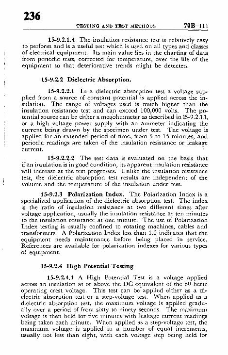
236 T E S T I N G AND T E S T M E T H O D S 70B-111
15-9.2.1.4 The insulation resistance test is relatively easy to perform and is a useful test which is used on all types and classes of electrical equipment. Its main value lies in the charting of data from periodic tests, corrected for temperature, over the life of the equipment so that deteriorative trends might be detected.
15-9.2.2 Dielectric Absorption.
15-9.2.2.1 In a dielectric absorption test a voltage sup- plied from a source of constant potential is applied across the in- sulation. The range of voltages used is much higher than the insulation resistance test and can exceed 100,000 volts. The po- tential source can be either a meg'ohmmeter as described in 15-9.2.1.1, or a high voltage power supply with an anameter indicating the current being drawn by the specimen under test. The voltage is applied for an extended period of time, from 5 to 15 minutes, and periodic readings are taken of the insulation resistance or leakage current.
15-9.2.2.2 The test data is evaluated on the basis that if an insulation is in good condition, its apparent insulation resistance will increase as the test progresses. Unlike the insulation resistance test, the dielectric absorption test results are independent of the volume and the temperature of the insulation under test.
15-9.2.3 Polarization Index. The Polarization Index is a specialized application of the dielectric absorption test. The index is the ratio of insulation resistance at two different times after voltage application, usually the insulation resistance at ten minutes to the insulation resistance at one minute. The use of Polarization Index testing is usually confined to rotating machines, cables and transformers. A Polarization Index less than 1.0 indicates that the equipment needs maintenance before being placed in service. References are available for polarization indexes for various types of equipment.
15-9.2.4 High Potential Testing
15-9.2.4.1 A High Potential Test is a voltage applied across an insulation at or above the DC equivalent of the 60 hertz operating crest voltage. This test can be applied either as a di- electric absorption test or a step-voltage test. When applied as a dielectric absorption test, the maximum voltage is applied gradu- ally over a period of from sixty to ninety seconds. The maximum voltage is then held for five minutes with leakage current readings being taken each minute. When applied as a step-voltage test, the maxinmm voltage is applied in a number of equal increments, usually not less than eight, with each voltage step being held for

' 237 70B-112 ELECTRICAL EQUIPMENT MAINTENANCE
an equal interval of time. The time interval between steps should be long enough to allow the leakage current to reach approximate stability, usually one or two minutes. A leakage current reading is taken at the end of each interval before the voltage is raised to the next level. A plot of test voltage versus insulation resistance is drawn as the test progresses. After the maximum test voltage is reached, a dielectric absorption test may be performed at. that voltage, usually for a five minute period.
15-9.2.4.2 The maximum permissible test voltages for acceptance tests performed on cables are listed in the Insulated Power Cable Engineers' Association (IPCEA) Standards for rubber, thermoplastic, and varnished cloth insulations, and in the Asso- ciation of Edison Illuminating Companies (AEIC) Standards for solid type impregnated paper insulation. Ordinarily, routine maintenance tests are conducted with a maximum test voltage at or below 75 percent of the maximum test voltage permitted for ac- ceptance testing.
15-9.2.4.3 Care should be taken in choosing the appropri- ate test voltage for routine maintenance tests on cables which have been in service for longer periods. If the level selected is too low, marginal weak spots may not be revealed; if the level is too high, damage to the insulation may result. Further, if it is inconvenient or impossible to disconnect switchgear, instrument transformers, or cutouts from the test circuit, it may be necessary to reduce the maximum test voltage to the level that this equipment can with- stand without damage.
Prior to testing, lightning arresters must be removed from the test circuit and wherever practical, all instrument transformers, switches, cutouts, and switchgear, so that if significant leakage currents are encountered during the test it will be known that these currents represent losses in the cable, not associated equipment. The test voltage should be applied from phase to ground on each conductor with the other conductors, the shields, and metallic jackets also connected to ground. The DC to AC (R.M.S.) test voltage ratios ordinarily used are as follows:
CABLE INSULATION RATIO
Rubber or Rubber-like, Ozone Resisting 3.0 to 1 Rubber or Rubber-like, other than Ozone Resisting 2.2 to 1 Impregnated Paper, Solid Type 2.4 to 1 Varnished Cloth 2.0 to 1 Polyethylene 3.0 to 1

238 T E S T I N G AND T E S T M E T H O I ) S 70B-113
15-9.2.4.3 When the step-voltage type of test is used, the condition of the cable is evaluated on the basis of 1) the absolute values of insulation resistance, 2) the slope of the curve of voltage versus insulation resistance, and 3) whether or not a significant downward "knee" appears in the curve at the higher levels of test voltage.
15-9.3 AC Testing.
15-9.3.1 High Potential Testing. AC High Potential Tests are made at voltages above the normal system voltage for a short time, such as one minute. The test voltage used for this test will ordinarily be twice the normal operating voltage plus 1,000 volts:
15-9.3.2 Insulation Power Factor Testing.
15-9.3.2.1 The power factor of an insulation is the cosine of the angle between the charging current vector and the impressed voltage vector when the insulation system is energized with an AC voltage. In other words, it is a measure of the energy component of the charging current. The term "Power Factor Testing" means any testing performed in order to determine the power factor of an insulation system. For low values of power factor, the dissipa- tion factor can be assumed to be the same as power factor. Power factor testing is a useful tool in evaluating the quality of insulation in Power, Distribution and Instrument Transformers, Circuit Break- ers, Rotating Machines, Cables, Regulators, and Insulating Liquids. The equipment to be tested should be isolated from the rest of the system, if practical, and all bushings or terminations should be cleaned and dried. The test should be conducted when the relative humidity is below 70 percent and when the insulation system is at a temperature above 32 ° F. Data obtained at relative humidity above 70 percent umst be interpreted to recognize the higher humidity.
15-9.3.2.2 The test equipment used should be sucti that the power factor or dissipation factor may be read directly or such that the charging volt-amperes and the dielectric losses may be read separately so that a ratio might be computed. The test equip- ment should also have suffmient electro-magnetic interference can- cellation devices and/or shielding to give meaningful test results even when used in an area of strong interference, such as an ener- gized substation. The test equipment should be able to produce and maintain a sinusoidal wave shape while performing the test at 60 hertz, and of sufficient capacity and voltage range to per- form the test at a minimum voltage of 2,500 volts or the operating voltage of the equipment under test, whichever is lower, but in no case less than 500 volts.

70B-114 ELECTRICAL EQUIPMENT MAINTENANCE
239
15-9.3.2.2 On transformer tests, the power factor of (1) each winding with respect to ground and (2) each winding with respect to each other winding, should be obtained. In addition, tests should be made of each bushing with a rated voltage above 600 volts, either using the power factor or capacitance tap if the bushing is so equipped or by use of a "Hot-Collar" test using a test electrode around the outside shell of the bushing.
15-9.3.2.3 On circuit breakers, the power factor of (1) each line-side and load-side bushing assembly complete with stationary contacts and interrupters, with the circuit breaker open, and (2) each pole of the circuit breaker with the breaker closed, should be obtained. In addition, tests should be made of each bush- ing as described above. Air magnetic circuit breakers should be tested both with and without arc chutes.
15-9.3.2.4 On AC rotating machines, the netural con- nection on the stator should be removed and a test of each winding with respect to the other two windings and ground should be ob- tained.
15-9.3.2.5 For cables, the power factor of each conductor with respect to ground should be obtained and a hot-collar test should be made of each pothead or termination. Power factor testing of insulating oil should be performed in accordance with ASTM D-924.
15-9.3.2.6 Evaluation of the data obtained should be based on (1) industry standards for the particular type of equipment tested, (2) correlation of data obtained with test data from other similar units tested, and (3) comparison of data with prev!ous test data on the same equipment (if available).
15-10 Protective Device Testing.
15-10.1 Fuses. There is no way to test the operation of fuses on a system since this type of device destroys itself while performing its protective function. The only test that can be performed on a fuse in the field is a continuity test to determine whether or not the fuse has "blown." A partial operational test may be performed if desired by passing a current through the fuse equal to or slightly less than its rated current to assure that the fuse will carry rated current without operating. If this is done, care should be taken not to exceed the "damage curve" of the fuse as published by the manu- facturer.
15-10.2 Circuit Breakers, General. Circuit Breakers can gen- erally be divided into two categories depending upon the applicable industry design standards:

240 T E S T I N G A N D T E S T M E T H O D S 70B-115
1. Molded Case Circuit Breakers. Designed, tested and evaluated in accordance with. NEMA AB-1 and Underwriters' Laboratories, Inc. Standards for Safety No. UL 489.
2. Low Voltage Power Circuit Breakers. Designed, tested and evaluated in accordance with NEMA SG-3 and ANSI C37.13.
15-10.2.1.1 Molded ease Circuit Breakers, General. Molded case circuit breakers are available in a wide variety of sizes, shapes and ratings. Voltage ratings - - by standard definitions - - are limited to 600 volts although special applications have been made to 1,000 volts. Current ratings are available from 10 through 4,000 amps. Molded case circuit breakers can be categorized gen- erally by the types of trip units employed as described in Sec- tion 10-5. Electrical testing should be performed in a manner and with the type of equipment required by the type of trip unit em- ployed.
15-10.2.1.2 Testing Thermal Magnetic Circuit Break- ers. The electrical testing of Thermal Magnetic Circuit Breakers can be divided into three steps:
1. Overload of individual poles at .300 percent of trip rating.
2. Verification Test Procedures
3. Verification of Manufacturer 's Published Data
Complete and detailed instructions for testing molded case cir- cuit breakers in accordance with the above steps is outlined in detail in the NEMA publication entitled: Procedures for Verifying Performance of Molded Case Breakers. Individual manufacturers also publish recommended testing procedures as well as time-current characteristic tripping curves.
15-10.2.1.3 Field Test ing in General . The procedures outlined in the above NEMA publication in Sections 2 and 3 are in- tended for checking the condition and basic electrical operation of circuit breakers, but they cannot be considered as Calibration Tests or comparisons to Laboratory Tests. Section 3 outlines fac- tors to be considered if laboratory accuracy is to be approached. I f checking indicates maloperation, the circuit breaker should be removed and sent to the manufacturer for investigation and test. It is not advisable to attempt repairs in the field. I f field testing under categories (2) and/or (3) above is required, then it is recommended that a competent field service team be employed and that instruc- tions be followed as recommended by the above NEMA publication.
15-10.2.1.4 Assistance. Manufacturers, electrical con- tractors and other competent service organizations will generally provide field-test services; some are equipped t o perform field

70B-116 ELECTRICAL EQUIPMENT MAINTENANCE
/,41
tests on any make unit. Such service will be found more practicable where accurate tests are required, and for all tests on circuit break- ers of 600 ampere capacity and above. This is in part due to the need for special heavy loading 'equipment, and also due to the difficulty of making suitable testing connections.
15-10.2.1.5 Over load Tes t ing Considerations. When testing circuit breaker tripping characteristics, it is recommended that the overcurrent tests be performed on individual poles at 300 percent of rated current. The reaction of the circuit breaker to this overload is in- dicative of its reaction throughout its entire overcurrent tripping range. This load is chosen as the test point because it is relatively easy to generate the required current in the field and the wattage per pole from line to load is large enough, so the dissipation of heat in the nonactive pole spaces is minor and does not affect the test results appreciably.
1 5 - 1 0 . 2 . 1 . 6 0 v e r c u r r e n t Tr ip Data. Table 15:-10.2.1.6 outlines the current and trip time values as recommended by NEMA. The min imum/max imum range of values in Table 15-10. 2.1.6 was developed to encompass most brands. For more specific values, refer to the manufacturer 's data for the circuit breaker being tested.
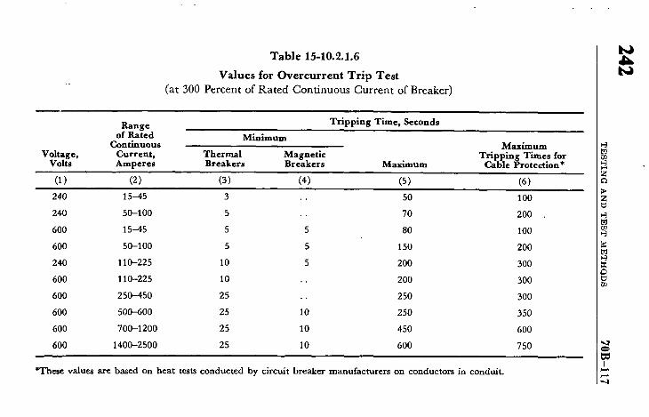
T a b l e 15-10.2.1.6
V a l u e s f o r O v e r c u r r e n t T r i p T e s t
(a t 300 P e r c e n t o f R a t e d C o n t i n u o u s C u r r e n t o f Breaker)
Range Tripping Time, Seconds of Rated Minimum
Continuous Maximum Voltage, Current, Thermal Magnetic Tripping Times for
Volts Amperes Breakers Breakers Maximum Cable Protection*
(1) (2) (3) (4) (5) (6)
240 15-45 3 . • 50 1 O0
240 50-100 5 .. 70 200
600 15-45 5 5 80 1 O0
600 50-100 5 5 150 200
240 110-225 10 5 200 300
600 110-225 10 .. 200 300
600 250-450 25 .. 250 300
600 500-600 25 10 250 350
600 700-1200 25 10 450 600
600 1400---2500 25 10 600 750
t,J
t,J
*These values are based on heat tests conducted by circuit breaker manufacturers on conductors in conduit.

70B-118 ELECTRICAL EQUIPMENT MAINTENANCE
243
15-10.2.1.7 Evaluation of Results. 1. Minimum Trip Times (Col. 3 and 4). Values shown
in Table 15-10.2.1.6 should not be considered significant in field testing unless nuisance tripping has been experienced. The values shown are provided as a guideline only. If minimum tripping times are lower than those shown in 15-10.2.1.6, the breaker should be re- tested after being de-energized and cooled for the required time.
2. Max imum Trip Times (Col. 5). Under normal test conditions, the circuit breaker will trip in less than the maximum values shown in 15-10.2.1.6, Column 5. Under improper test con- ditions the maximum values may exceed those given in 15-10.2.1.6.
3. Max imum Tripping Times for Cable Protection (Col. 6). I f the test value exceeds the maximum tripping time shown in Col. 5 but fails below the maximum tripping times for cable dam- age, the circuit breaker is providing an acceptable level of pro- tection. Coordination with other protective devices should be con- sidered before replacing a circuit breaker which trips beyond the time-current curve.
15-10.2.2 Testing Instantaneous Only Circuit Breakers. The testing of instantaneous only circuit breakers requires the use of elaborate constant rate of rise test equipment coupled with ac- curate current monitoring instrumentation - - preferably digital read-out - - for accurate confirmation of manufacturers test results. Unless this type of equipment is available, it is recommended that these breakers be referred to the manufacturer, electrical contractor or other competent service organization when calibration is re- quired.
15-10.2.3 Field Tes t ing of Circuit Breakers Employing Solid State Trips. Breakers employing solid state trip units offer testing opportunities not readily available in standard thermal magnetic and/or instantaneous only circuit breakers. Since solid state trip units are designed to operate on low level currents ob- tained via the secondaries of current transformers mounted on the phase conductors, small compact test kits can be utilized in per- forming field tests with a high degree of accuracy. Since these breakers have unique design characteristics, the manufacturers should be consulted for available test kits and testing instructions. Attempted field repair oJ the solid state trip units should be avoided. Any suspected malfunction should be referred to a competent service group.
15-10.2.4 Low Voltage Power Circuit Breaker Testing.
15-10.2.4.1 Series Overcurrent Device Testing. Most low voltage power circuit breakers are equipped with series over-
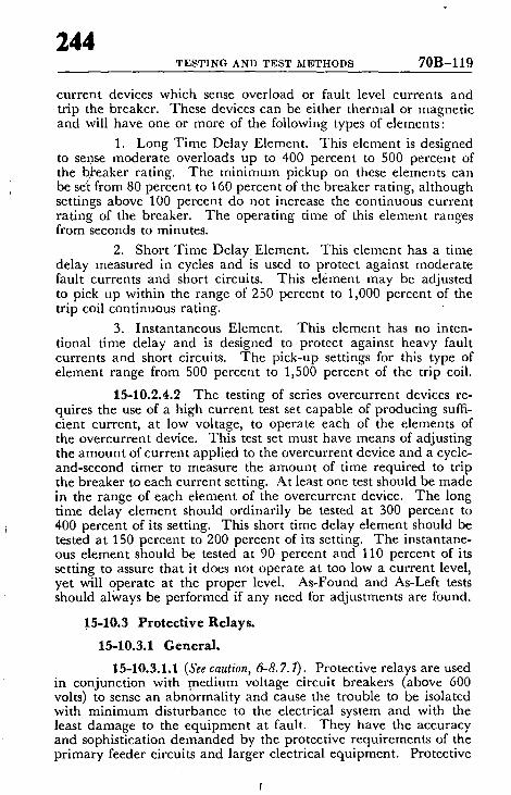
244 T E S T I N G AND T E S T M E T H O D S 70B-119
current devices which sense overload or fault level currents and trip the breaker. These devices can be either thermal or magnetic and will have one or more of the following types of elements:
1. Long Time Delay Element. This element is designed to sense moderate overloads up to 400 percent to 500 percent of the b)~eaker rating. The minimum pickup on these elements can be set from 80 percent to 160 percent of the breaker rating, although settings above 100 percent do not increase the continuous current rating of the breaker. The operating time of this element ranges from seconds to minutes.
2. Short Time Delay Element. This element has a time delay measured in cycles and is used to protect against moderate fault currents and short circuits. This element may be adjusted to pick up within the range of 250 percent to 1,000 percent of the trip coil continuous rating.
3. Instantaneous Element. This element has no inten- tional time delay and is designed to protect against heavy fault currents and short circuits. The pick-up settings for this type of element range from 500 percent to 1,500 percent of the trip coil.
15-10.2.4.2 The testing of series overcurrent devices re- quires the use of a high current test set capable of producing suffi- cient current, at low voltage, to operate each of the elements of the overcurrent device. This test set must have means of adjusting the amount of current applied to the overcurrent device and a cycle- and-second timer to measure the amount of time required to trip the breaker to each current setting. At least one test should be made in the range of each element of the overcurrent device. The long time delay element should ordinarily be tested at 300 percent to 400 percent of its setting. This short time delay element should be tested at 150 percent to 200 percent of its setting. The instantane- ous element should be tested at 90 percent and 110 percent of its setting to assure that it does not operate at too low a current level, yet will operate at the proper level. As-Found and As-Left tests should always be performed if any need for adjustments are found.
15-10.3 Protective Relays.
15-10.3.1 General.
15-10.3.1.1 (See caution, 6-8.7. I). Protective relays are used in conjunction with medium voltage circuit breakers (above 600 volts) to sense an abnormality and cause the trouble to be isolated with minimum disturbance to the electrical system and with the least damage to the equipment at fault. They have the accuracy and sophistication demanded by the protective requirements of the primary feeder circuits and larger electrical equipment. Protective

70B-120 ELECTRICAL EQUIPMENT MAINTENANCE
245
relays designed to be responsive to an abnormal excursion in cur- rent, voltage, frequency, phase-angle, direction of current or power flow, etc., and with varying operating characteristics are com- mercially available. Each relay application requires custom engi- neering to satisfy the parameters of its particular intended function in the system.
15-10.3.1.2 The more common protective relay is of the electromechanical type. Tha t is, some mechanical element such as an induction-disk, an induction cylinder or magnetic plunger is caused to move in response to an abnormal change in a parameter of the electrical system. The movement can cause a contact in the control circuit to operate, tripping the related circuit breaker. Protective relays should be acceptance tested prior to being placed in service, and periodically thereafter to insure reliable performance. In a normal industrial application, periodic testing should be. done at least every two years.
15-10.3.1.3 The various facets involved in testing protec- tive relays can be listed as follows:
1. The technician must understand the construction, op- eration and testing of the particular relay.
2. The manufacturer 's instruction bulletin, as indentified on the name plate of the relay, should be available to him.
3. The technician should be given the settings to be ap- plied to each particular relay, and the test points. This data is often furnished on a time-current curve of the coordination study dis- playing the characteristic of the relay.
4. A test instrument, suitable to accurately accommodate the various acceptance and periodic maintenance tests described in the manufacturer 's instruction manual, should be available.
5. Most protective relays can 'be isolated for testing while the electrical system is in normal operation. However, an opera- tion of the breaker is required to ascertain that the operation of the relay con'tacts will trigger the intended reaction, such as to trip the associated circuit breaker.
15-10.3.2 Testing Procedure.
15-10.3.2.1 Inspect ion. I f required or desirable, each relay should be removed from its case for a thorough inspection and cleaning. If the circuit is in service, remove one relay at a time so as not to totally disable the protection. The areas of inspection are detailed in the manufacturer 's instruction ma/iual. These generall), consist of inspection for loose screws, friction in moving
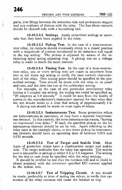
246 T E S T I N G AND T E S T M E T H O D S 70B-121
parts, iron filings between the induction disk and permanent magnet and any evidence of distress with the relay. The fine silver contacts should be cleaned only with a burnishing tool.
15-10.3.2.2 Settings. Apply prescribed settings or ascer- tain that they have been applied to the relay.
15-10.3.2.3 Pickup Test. In the case of a time-overcur- rent relay, its contacts should eventually creep to a closed position with a magnitude of current introduced in its induction coil equal to the tap setting. The pickup is adjusted by means of the re- straining spiral spring adjusting ring. A pickup test on a voltage relay is made in much the same manner.
15-10.3.2.4. Timing Test. [n the case of a time-overcur- rent relay, one or more timing tests are made at anywhere from two to ten times tap setting to verify the time current character- istic of the relay. One timing point should be specified in the .pre- scribed settings. Tests should be made With the relay in its panel and case, and the time test run at the calibration setting.
For example, in the case of one particular overcurrent relay having a 5 ampere tap setting, the timing test could be specified as, "25 amperes at 0.4 seconds." It could be seen from the family of curves in the manufacturer's instruction manual for that relay that the test should result in a time dial setting of approximately 1.6.
A timing test should be made on most types of relays.
15-10.3.2.5 Instantaneous Test. Some protective relays are instantaneous in operation, or may have a separate instantane- ous element. In this context, the term instantaneous means, "having no intentional time delay." If used, the specified pickup on the in- stantaneous element should be set by test. Again referring to the relay used in the example above, at two times pickup its instantane- ous element should have an operating time of between 0.016 and 0.030 seconds.
15-10.3.2.6 Test of Targe t and Seal-In Unit. Most types of protective relays have a combination target and seal-in unit. The target indicates that the relay has operated. The seal-in unit is adjustable to pickup at either 0.2 or 2.0 amperes. The setting for the seal-in unit must be specified with the relay settings.
It should be verified by test that the contacts will seal in (hold in closed ~position) with the minimum specified DC current applied in the seal-in unit.
15-10.3.2.7 Test of Tr ipp ing Circuit. A test should be made, preferably at time of testing the relays, to verify that op- eration of the relay contacts will cause the breaker to trip.
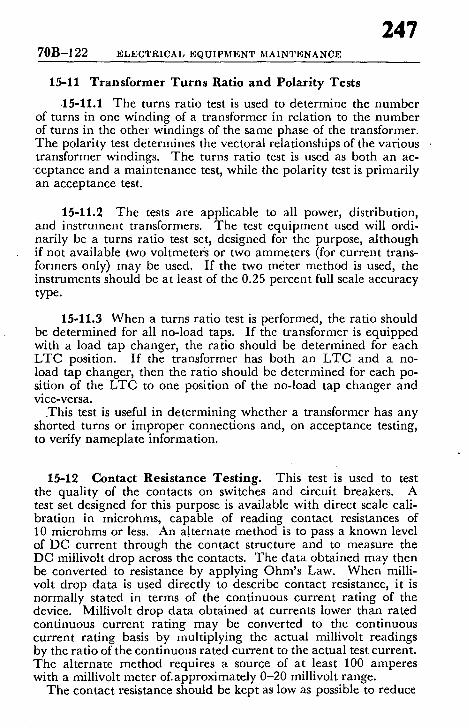
70B-122 ELECTRICAL EQUIPMENT MAINTENANCE
247
15-11 Transformer Turns Ratio and Polarity Tests
.15-11.1 The turns ratio test is used to determine the number of turns in one winding of a transformer in relation to the number of turns in the other windings of the same phase of the transformer. The polarity test determines the vectoral relationships of the various transformer windings. T he turns ratio test is used as both an ac-
cep tance and a maintenance test, while the polarity test is primari ly an acceptance test.
15-11.2 The tests are applicable to all power, distribution, and instrument transformers. T he test equ ipment used will ordi- narily be a turns ratio test set, designed for the purpose, a l though if not available two voltmeters or two ammeters (for current trans- formers only) may be used. I f the two meter method is used, the instruments should be at least of the 0.25 percent full scale accuracy type.
15-11.3 When a turns ratio test is performed, the ratio should be determined for all no-load taps. I f the transformer is equipped with a load tap changer, the ratio should be determined for each L T C position. I f the transformer has both an L T C and a no- load tap changer, then the ratio should be determined for each po- sition of the L T C to one position of the no-load tap changer and vice-versa.
.This test is useful in determining whether a transformer has any shorted turns or improper connections and, on acceptance testing, to verify nameplate information.
15-12 Contact Resistance Testing. This test is used to test the quali ty of the contacts on switches and circuit breakers. A test set designed for this purpose is available with direct scale cali- bration in microhms, capable of reading contact resistances of 10 microhms or less. An alternate method is to pass a known level of DC current through the contact structure and to measure the DC millivolt drop across the contacts. The da ta obtained may then be converted to resistance by applying O h m ' s Law. W h e n milli- volt drop data is used directly to describe contact resistance, it is normally stated in terms of the continuous current rat ing of the device. Millivolt drop da ta obtained at currents lower than rated continuous current rat ing may be converted to the continuous current rating basis by mult iplying the actual millivolt readings by the ratio of the continuous rated current to the actual test current. The alternate method requires a source of at least 100 amperes with a millivo|t meter of .approximately 0-20 millivolt range.
The contact resistance should be kept as low as possible to reduce
248 T E S T I N G AND T E S T M E T H O D S 70B-123
power losses at the contacts with the resultant localized heating; which will shorten the life of both the contacts and nearby insula- tion.
15-13 Grounding Electrode Resistance Testing. Grounding electrode resistance testing is used to determine the effectiveness and integrity of the grounding system. An adequate grounding system is necessary to (1) provide a discharge path for lightning, (2) prevent induced voltages caused by surges on power lines from damaging equipment connected to the power line, and (3) main- tain a reference point of potential for instrumentation safety. Peri- odic testing is necessary because variations in soil resistivity are caused by changes of soil temperature, soil moisture, conductive salts in the soil, and corrosion of the ground connectors. The test set used will ordinarily be a ground resistance test set, designed for the purpose, using the principle of the fall of potential of AC circu- lated current from a test spot to the ground connection under test. This instrument is direct reading with a scale calibrated in ohms of ground resistance.
15-14 Circuit Breaker Time-Travel Analysis 15-14.1 This test, used on medium and high voltage circuit
breakers, provides information as to whether the operating mech- anism of the circuit breaker is operating properly. -It presents in graphical form the position of the breaker contacts versus time. From this test can be determined the opening and closing speeds of the breaker, the interval time for closing and tripping and the con- tact bounce. The test provides information which can be used to detect problems such as weak accelerating springs, defective shock absorbers, dashpots, buffers, and closing mechanisms.
15-14.2 The test is performed by a mechanical device which is attached to the breaker. There are several types of devices avail- able to perform this function. With one device, a rotating drum, with chart attached, is temporarily connected to the chassis or tank of the breaker. A movable rod with marking device attached, is installed on the lift rod portion of the breaker. As the breaker is opened or closed, the marking device indicates the amount of contact travel on the chart as the drum rotates at a known speed. With another available device, a transducer is attached to the movable rod and the breaker operation is recorded on an oscillo- graph.

70B-124 ELECTRICAL EQUIPMENT MAINTENANCE
249
15-15 I n f r a r e d Inspec t ion . Infrared sensors of various types can be used to detect the presence of abnormal heat on an elec- trical system. These devices are able to detect hot spots at a dis- tance, with the system energized. They are very useful in routine maintenance inspection in locating bad joints, switch parts, ter- minals, and overloaded lines. Some of the devices available present the temperature information on a scale calibrated in degrees; others present television pictures with the hotspots showing as very bright images on the screen.
15-16 Faul t -Gas Analysis. The analysis of the percentage of combustible gases present in the nitrogen cap of sealed, pressurized oil filled transformers can provide information as to the likelihood of incipient faults in the transformer. When arcing or excessive heating occurs below the top surface of the oil, some oil decomposes. Some of the products of the decomposition are combustible gases which rise to the top of the oil and mix with the nitrogen above the oil.
The test set used for this test is designed for the purpose. A small sample of nitrogen is removed from the tr/msformer and analyzed. The set has a direct reading scale calibrated in percent of combustible gas. Ordinarily, the nitrogen cap in a transformer will have less than one-half percent combustible content. As a problem develops over a period of time the combustible content can rise to ten or fifteen percent.
A suggested evaluation of the test results is as follows :
PERCENTAGE OF COMBUSTIBLE GAS
0.0tol .0
1.0to2.0
2 . 0 t o 5 . 0
Over 5.0
EVALUATION
No reason for concern. Make tests at regularly scheduled intervals.
Indication of contamination or slight incipient fault. Make more frequent readings and watch trend.
Begin more frequent readings immedi- ately. Prepare to investigate cause by internal inspection.
Remove transformer from service and m a k e internal inspection.
15-17 Insu l a t i ng L i q u i d Analysis. Regular tests, on a semi- ammal basis, should be made on insulating oils and Askarels. Samples should be taken from the equipment in accordance with A S T M Method D923-70. The most commonly performed mainte-

250 T E S T I N G A N D T E S T M E T H O D S 70B-125
nance tests performed on used insulating liquids, together with the appropria te A S T M test methods are shown in Table 15-17. Also included in this table are suggested limits to be used to determine whether the liquid is in need of recondit ioning or reclamation. For comparison, typical test values for new oil are also included in the table.

Test For:
Table 15-17
Summary of Maintenance Tests for Insulating Liquids
ASTM Method of Test Test Limits for Maintenance Typical N e w Liquid Valve
Z I °
Acidity, Approximate
Color, ASTM
Dielectric Breakdown Voltage
Examination, Visual, Field
Interfacial Tension (Oil Only)
D1534-64 or D1902-64
D1500-64 (1968) (Petroleum Oils) (Use also for maintenance testing
of Askarel.)
D877-67 (Disk Electrodes) or D1816-67 (VDE Electrodes)
D1524-69 (Petroleum Oils) or D1702-65 (Askarels)
D971-50 (1968) (Ring Method) or D2285-68 (Drop Weight)
Neutralization Number D974-54 (1968) or D664-58
Power Factor D924-65 (1969)
*Replace for any value greater than 0.014
Same as Neutralization Number
4.0 Max. (Oil) 2.0 Max. (Askarel)
22 KV Min. (Oil) 25 KV Min. (Askarel)
Cloudy, dirty, or visible water
18 Dynes/Cm. Min.
0.40 Max. (Oil) *(Askarel)
1.8% Max. (Oil) .5-2.0% (Askarel)
Below
1.0 Max. (Oil and Askarel)
26 KV (Oil) 30 KV (Askarel)
Clear
35 Dynes/Cm. Min.
0.04 Max. (Oil) 0.014 Max. (Askarel)
0.1% Max. (25°C) (Oil) .2-.5% Max. (25°C) Askarel

252 TESTING AND TEST METHODS 70B-127
15-18 Rotating Mach ine Test ing
15-18.1 Insulat ion Resistance Testing.
15-18.1.1 This testing procedure applies to armature and rotating or stationary field windings. A hand crank, rectifier or bat tery-operated instrument is suitable for testing equipment rated to 600 volts. For equipment rated over 600 volts, a 1000 volt or 2500 volt motor driven or rectifier operated instrument is recom- mended for op t imum test results. Opera t ing machines should be tested immediately following shutdown when the windings are hot and dry. On large machines the temperature should be re- corded and converted to a base temperature in accordance with I E E E 43 to provide continuity for comparat ive purposes. Always disconnect all voltage sources, l ightning arrestors, and capacitors or other potential low insulation sources before making insulation measurements. Lead-in cables or busses and line side of circuit breakers or starters can be tested as a par t of the circuit provided a satisfactory reading is obtained. I f the insulation resistance is below the established minimum, the circuit components should be tested separately until the low insulation reading is located. In- sulation resistance history based on tests conducted on new motors or after rewind, cleaning or from recorded data made under uni- form conditions form a very useful basis for interpretation of a ma- chine winding condition. When compar ing records of periodic tests any persistent downward trend is an indication of insulation trouble even though the values may be higher than the recommended min imum safe values listed below.
15-18.1.2 Insulat ion resistance readings taken for purposes of correlation should be made at the end of a definite interval following the application of a definite test voltage. For purposes of standardization, 60 seconds application is recommended where short time single readings are to be made on windings and where comparisons with earlier and later da ta are to be made. Recom- mended min imum acceptable insulation values without further in- vestigation are as follows:
AC and DC motors ~ 500,000 Ohms 250 volts and less J
AC and DC motors ~ 1 megohm 1000 volta or less J
AC and DC motors \ 1 megohm per Over 1000 volta J" 1000 volts

70B-128 ELECTRICAL EQUIPMENT MAINTENANCE
253
15-18.2 Dielectric Absorption Test ing. A more complete and preferred test applies the voltage for ten minutes or more to develop the dielectric absorption characteristic. The curve ob- tained by plotting insulation resistance against time gives a good indication of moist or dirty windings. A steady rising curve is in- dicative of a clean, dry winding. A quick flattening curve is the result of leakage current through or over the surface of the winding and is indicative of a moist or dirty winding. I f facilities are not available for a ten minute test, readings may be taken at 30 and 60 seconds. The ratio of the 60 to 30 second or the 10 to 1 minute ratio will serve as an indication of the winding condition. The following table should serve as a guide in interpreting these ratios.
CONDITION 60:30 SECOND RATIO 10:I MINUTE RATIO Dangerous - - Less than'o 1 Poor Less than 1.1 Less than 1.5 Questionable 1.1 to 1.25 1.5 to 2 Fair 1.25 to 1.4 2 to 3 Good 1.4 to 1.6 3 to 4 ,Excellent Above 1.6 Above 4
15-18.30verpotential Testing. 15-18.3.1 Overvoltage tests are performed dur ing normal
maintenance operations or after servicing or repair of impor tan t machines. Such tests, made on all or parts of the circuit to ground insure that the insulation level is sufficiently high for continued safe operation. Both AC and DC test equipment is available. There is no conclusive evidence that one method is preferred over the other. However, where equipment using several insulating materials is tested, AC stresses the insulation more nearly to actual operat ing conditions than DC. Also, more comparable data have been accumulated since AC testing has had a head start. However, the use of D3 has several advantages and is rapidly gaining favor with increased usage. The test equipment is much smaller, lighter in weight and lower in price. There is far less possibility of damage to equipment under test and DC tests will give more information than is obtainable with AC testing.
15-18.3.2 The test overvoltages which should be applied will depend on the type of machine involved and level of reliability required from the machines. However, it should be of sufficient magni tude to search out weaknesses in the insulation which might cause failure. S tandard overpotential test voltage when new is

254 TESTING AND TEST METHODS 70B-129
twice rated voltage plus 1000 volts AC. On older or repaired ap- paratus, tests are reduced to approximately 50 to 60 percent o f the factory (new) test voltage. (Reference IEEE No. 4.) For DC tests the AC test voltage is multiplied by a factor (1.7) to represent the ratio between the direct test voltage and alternating rms voltage. (Reference IEEE No. 95.)
15-18.3.3 A high potential test made to determine the con- dition of the insulation up to a predetermined voltage level is diffi- cult to interpret. I t is common practice to compare known good results against test specimens to determine what is acceptable or fails the'test. For a DC high potential test the shape of the leakage current plotted against voltage rise is an additional used criteria. As long as the knee of the curve (which indicates impending break- down; point C below) does not occur below the maximum required test voltage and as long as the shape of the curve is not too steep compared with that of similar equipment or prior test of the same equipment, the results may be considered satisfactory. It should be recognized that if the windings are clean and dry, overvohage tests will not detect any defects which are in the end turns or in lead-in wire located away from the stator iron.
Figure 15-18.3.3
100
,.',- dl /BREAKDOWN
~ 60 ,, o -- MAX. n- TEST U
40 VOLTAGE.
20 ~
,5 10 15 20 25 30 3.5 KILOVOLTS

70B-130 ELECTRICAL EQUIPMENT MAINTENANCE
255
15-18.4 Other Insulat ion Tests. There are several other types of insulation tests, depending on the need and desired results. These are listed below; however, these more complex tests are not employed unless apparatus performance indicates these tests must be made and experienced testers are available with the test equipment.
Turn to Turn Insulation Slot Discharge and Corona Winding Impedance Test Power Factor Value Stator Core Flux Test

256 BIBLIOGRAPHY 70B-131
APPENDIX A BIBLIOGRAPHY
A-1 Introduction
A-I.1 This bibliography lists some of the more widely recog- nized sources of maintenance and testing information. There are many excellent text books by individual authors that are not listed because they are too numerous and information on them is avail- able from the various publishers.
A-1.2 For those who are interested in implementing an effective EPM program or improving an existing one, a suitable reference library should be readily available. Size of the plant and the extent of its maintenance and servicing operations will determine the desired publications for the reference library.
A-1.3 The need to use manufacturers' service manuals and in- structions furnished with specific equipment or apparatus has been previously mentioned and cannot be overemphasized. Additionally, there are many sources of helpful information on general and specific maintenance, troubleshooting, test methods, test instru- ments and their use. Some of these are available without cost, but most entail a nominal charge. Publishers of technical and trade magazines are another important source of pertinent litera- ture. Some can provide, without charge, reprints of specific arti- cles, or for a nominal fee, a compilation of reprints of articles on a particular subject.
American National Standards Institute
Guide for Installation and Maintenance of Oil-Immersed Trans- formers - - ANSI C57.93-1958, NEMA TR5-1956.
Guide for Installation and Maintenance of Dry-Type Transformers ANSI C57.94-1958.
Guide for Application, Operation, and Maintenance of Distribution Cutouts and Fuse Links, Secondary Fuses, Distribution Enclosed Single-Pole Air Switches, Power Fuses, Fuse Disconnecting Switches, and Accessories i ANSI C37.47-1969.
70B-132 ELECTRICAL EQUIPMENT MAINTENANCE
257
Part I of the National Electrical Safety Code entitled Rules for the Installation and Maintenance of Electric Supply Stations and Equipment, ANSI C2.1-1971.
American Petroleum Institute
Guide for Inspection of Refinery Equipment, Chapter X I V Electrical Systems.
American Society for Testing and Materials
Low-Voltage Rubber Insulating Gloves - - ASTM 1700.
Rubber Insulating Gloves - - ASTM D 120-70, ANSI J6.6-1970.
Rubber Insulating Blankets - - ASTM D 1048-70, ANSI J6.4-1971.
Rubber Insulating Hoods - - ASTM D 1049-59 (1970), ANSI J6.2-1951 (R1971).
Rubber Insulating Line Hose - - ASTM D1050-59 (1970), ANSI J6.1-1950 (R1971).
Rubber Insulating Sleeves - - ASTM D1051-70, ANSI J6.5-1971.
Factory Mutual Engineering Corporation
Handbook of Industrial Loss Prevention, Chapter 32.
Institute of Electrical and Electronics: Engineers
Electrical Power Distribution for Industrial Plants - - IEEE No. 141.
Electric Systems for Commercial Buildings - - IEEE No. 241.
Graphic Symbols for Electrical and Electronics Diagrams IEEE No. 315-1970, ANSI Y32.2-1970.
Guide for Making Dielectric Measurements in the Field - - IEEE No. 62.
Guide for Acceptance & Maintenance of Insulating Oil in Equip- ment - - IEEE No. 64.
Guide for Insulation Maintenance for Large AC Rotating Ma- chinery - - IEEE No. 56.
Guide for Operat ion and Maintenance of Turbine-Generators - - IEEE No. 67.

258 BIBLIOGRAPHY 70B-133
Guide for Maintenance of Transformer Askarel - - IEEE No. 76.
Guide for Safety in AC Substation G r o u n d i n g - IEEE No. 80.
Guiding Principles for Dielectric Tests - - IEEE No. 51.
Insulation Testing of Large AC Rotating Machinery - - IEEE No. 95.
Measurement of Voltage in Dielectric Tests - - IEEE No. 4-1968, ANSI C68.1-1968.
Test Code for Power Factor Testing of Mineral-Oil Insulated Power Transformers - - IEEE No. 75.
Recommended Practice for Maintenance. Testing, and Replace- ment - - Large Stationary Type Power Plant and Substation Lead Storage Batteries - - IEEE 450-72.
McGraw-Hill Publishing Co.
Industrial Power Systems Handbook, D. Beckman.
Preventive Maintenance of Electrical Equipment, C. I. Hubert.
National Electrical Manufacturers Association
AC High-Voltage Circuit Breakers - - NEMA No. SG-4-1968, see part 6 of Instructions for the Installation, Operation and Care of.
Maintenance Motors and Generators - - NEMA No. RPI-1968.
Procedures for Verifying Performance of Molded Case Circuit Breakers - - 1971.
National Fire Protection Association
National Electrical Code NFPA-70, ANSI C1-1975.
National Safety Council
Cleaning Machinery and Electric Motors - - No. 285.
Industrial Electric Substations - - No. 559.
Lead-Acid Storage Batteries - - No. 246.
Methods of Locking Out Electrical Switches - - No. 237.
Westinghouse Electric Corp.
Inspection and Test of Electrical Equipment - - MB-3051. Maintenance Hints - - HB-6001-P.

70B-134 ELECTRICAL EQUIPMENT MAINTENANCE
259
ADDRESSES (FOR BIBLIOGRAPHY)
American National Standards Institute, Inc. (ANSI), 1430 Broad- way, New York, NY 10018
American Petroleum Institute (API), 1801 K Street NW, Wash- ington, DC 20006.
American Society for Testing and Materials (ASTM), 1916 Race St., Philadelphia, PA 19103.
Chemical Rubber Co., 18901 Cranwood Parkway, Cleveland, OH 44128.
E. P. Dutton & Co., 201 Park Avenue So., New York, NY 10003.
Factory Mutual Engineering Corp., 1151 Boston-Providence Turn- pike, Norwood, MA 02062.
Gale Research Co., 1400 Book Tower, Detroit, MI 48226.
Hayden Book Co., Inc., 116 W. 14th St., New York, NY 10011.
Howard W. Sams Co., Inc., 4300 W. 62nd St., Indianapolis, IN 46206.
Institute of Electrical & Electronics Engineers, (IEEI~) 345 E. 47th St., New York, NY 10017.
John Wiley & Sons, Inc., 605 Third Ave., New York, NY 10016.
McGraw-Hill, Inc., 1221 Avenue of the Americas, New York, NY 10020.
National Electrical Manufacturers Association (NEMA), 155 E. 44th St., New York, NY 10017.
National Fire Protection Association (NFPA), 470 Atlantic Ave., Boston, MA 02210.
National Safety Council (NSC), 425 N. Michigan Ave., Chicago, IL 60611.
Prentice-Hall, Inc., Inglewood Cliffs, NJ 07632.
Reinhold Publishing Co., 430 Park Ave., New York, NY 10022.
TAB Books, Blue Ridge Summit, PA 17214.
Technical Publishing Co., 1301 South Grove Ave., Barrington, IL 60010.
Westinghouse Electric Corp., Apparatus Repair Division, Pitts- burgh, PA.

260 .INSPECTIONS 70B-135
Appendix B
Suggestions for Inclusion in
A Walk-Through Inspection Check List
These suggested items are directed toward minimizing the day- to-day electrical hazards. The list is not complete, nor do the items necessarily appear in order of importance. It is presented as a guide for the preparation of a check list that should be developed for each plant. Because of the similarity to the plant fire prevention inspection, both inspections may be carried out by the same per- sonnel.
Flexible Cords (Including Those on Appliances). Heater-type cords are required for portable heating appliances, such as toasters, grills, and coffee makers. Check condition for badly worn or frayed spots, splices (not permitted), improper type, current-carrying ca- pacity too small.
Plugs and Connectors. Check for stray' strands and loose terminals. Are they grounding type where required for specific appliances? Green conductor must be connected to grounding pin.
Extension Cords. Are they used in place of permanent wiring, of excessive length, of proper type? They should not pass through walls, partitions, or doors.
Mult iple Current-Taps . Are they used because of too few recep- tacles? Note particularly suchareas as canteens, lunchrooms, and offices.
Appliances: Grills, toasters, and similar equipment should be permanently spaced from combustible material.
Heat ing Appliances: Where used with combustible material such appliances generally require a signal light to indicate when "O n . "
Hot Water Heaters. ~Check for proper electrical protection. Manually operate the combina t ion temperature and pressure relief valve to be sure it is free and the drainline is clear. Visually check setting,
Office Equipment . Check condition of flexible cords, plugs, and connectors. Look for excessive use of extension cords and multiple current taps.

70B-136 ELECTRICAL EQUIPMENT MAINTENANCE
261
Receptacle Outlets. Three-pole grounding-type receptacles are generally required. Check each receptacle for continuity of ground- ing connection, using suitable test instrument. Are special receptacle configurations used for those supplying unusual voltages, frequencies, etc. Are they well-marked or identified? Note particularly missing faceplates, receptacles showing signs of severe arcing, loose mount- ing, etc. "
Portable Equipment (Tools, Extension Lamps and Extension Cords)( In shop or tool room after each use, check for isolation be- tween live parts and frame. Note condition of cord and plug. Is continuity maintained between frame and grounding pin of plug? The green conductor should connect only to the plug grounding pin. On lamps check condition of guards~ shields, etc. See the National Electrical Code, NFPA No. 70, for portable hand lamps; metal- shell, paper-lined lampholders for hand lamps are not permitted.
Light ing Fixtures. All lighting fixturcs should be labeled and grounded. See the National Electrical Code, NFPA No. 70, for connection of electric-discharge lighting fixtures. These may be connected by suitable, 3-conductor flexible cord where visible for its entire length and terminated at outer end in a grounding- type attachment plug or busway plug. No fixtures should be lo- cated close to highly combustible material. Note location of fix- tures having burned out bulbs or tubes; where fixtures are heavily coated with dust, dirt, or other material; and where the reflectors are in need of cleaning.
Equipment Grounding: Where machinery and/or wiring en- closures are grounded through the conduit system, look for broken or loose connections at boxes and fittings, flexible connections, and exposed ground straps. Multiple bonding of conduit and other metallic enclosures to interior water piping systems including sprin- kler systems, is sometimes used as a precaution where building vibration is severe, even though a separate equipment grounding conductor is run with the circuit conductors inside of the conduit.
Yard Transformer Stations. Note condition of transformers, fence, gates, and locks. Yard and equipment should be free of storage of combustible material, weeds, grass, vines, birds' nests, etc. Watch for indication of localized overheating indicated by conductor dis- coloration. Indication of excessive transformer temperature, pres- sure or oil leakage should be noted.
Services. ~v'isually check condition of weatherheads and weather- hoods to determine that they remain in good condition. Eliminate birds' and rats' nests, etc. At the same time determine the ap- parent condition of lightning arresters, surge capacitors, grounding conductors, and grounds. Are switches safely and readily ac- cessible?

262 INSPECTIONS 70B-137
Switchrooms and Motor Control Centers. Check to see that they are clean and used for no other purpose. They should be free of storage of any kind, especially combustible material. Ventila- tion equipment should be in working condition and unobstructed. Notice and promptly report any unusual noises or odors. Metering equipment should be checked for high or low voltage and current, and anyAndication of accidental grounding (ungrounded systems). Are switches'and motor controllers properly identified as to func- tion; are fire extinguishers in place, of suitable type and charged?
~Grouped Electrical Control Equipment (Such As May Be Mounted on Walls, Etc.). Are they protected from physical dam- age" and readily accessible? Are any equipment enclosures damaged or have missing or open covers? Are any live parts exposed? Re- port any condition preventing quick or ready access.
Enclosures of Electrical Parts (Motor Control Equipment, Junction Boxes, Switches, Etc.). Are covers secured in place? Report location of broken or loose conduit, wiring gutters, etc.
Missing dust caps should be replaced.
Hazardous Location Equipment. All cover bolts should be in place and tight. Permanent markings should not be obstructed by paint. Examine joints between cover and case for signs of having been pried open in removing cover. This may have damaged the mating surfaces of the joints. Excessive accumulations of dust and dirt should be noted for removal from all enclosures, including motors, which also should be examined for obstructed ventilation. Note and report the use of nonexplosion-proof electric equipment, including lighting, which may have been installed in the haz- ardous location area.
Emergency Equipment.
(1) Exit lights should all be functioning properly.
(2) Emergency lights should all be in working condition. Periodic tests are recommended to be sure that they function when normal lighting is lost.
(3) Emergency power supplies such as batteries, engine driven generators, etc., normally receive scheduled tests. Check records of periodic tests. Are fuel and cooling supplies for engine drives adequate? Are fire extinguishers in place, of proper type and charged?
(4) Alarm systems, such as for fire, intrusion, smoke detection, sprinkler waterflow and fire pumps, also receive periodic tests. Check records of these tests to be sure that all signals are properly transmitted and equipment is in good working condition.

70B-138 ELECTRICAL EQUIPMENT MAINTENANCE
263
Appendix C How to Instruct
C-1 Introduction. Training is basically a process for changing behavior. These behavioral changes are the product of new knowl- edge, reshaped attitudes, replaced skills, and newly acquired skills that express themselves, or become obscrvable, as improved work techniques of the learner.
The trainer's function is to structure the instruction process in a manner that will make learning take place more effectively and in the shortest period of time.
C,-2 Shortcomings of Learning by Trial and Error. Trial and error learning is learning at random. It is slow; it is costly in terms of time and in mistakes. It also is costly because it involves so much "unlearning" of incorrect practices and "relearning" after the mistakes have been made.
Trial and error is the instructional process that continues to dominate industry. Its inefficiency can be illustrated by examining the case of the newly hired maintenance electrician assigned to instrument circuit repair work until "he gets the feel of the plant and 'learns' his way around."
Assmne that the assignment is to disconnect an instrmnent from the power source so that an instrument technician can change out a defective chart drive motor.
Consistent with apparent good safety practice, and without consulting anyone, the electrician opened the switch that fed power to the entire instrument panel.
Loss of control of the process resulted in major product spoilage.
This example illustrates what may happen any time people are put on jobs, simple or complex, without giving them organized instruction, either personally on the job or in groups off the job.
An even clearer illustration of the inefficiency of trial and error learning is the example of an inexperienced maintenance elec- trician who is charged with responsibility for motor trip-out trouble- shooting, but who receives no formal instruction on this subject, which to him is unfamiliar.
His first attempts will include many blind alleys, such as going to the job location without the proper tools, a random inspection of the motor starter, the motor and the driven load or a random replacement of heater elements. As the number of his attempts to correct motor trip-outs increases he may learn to avoid many

264 HOW TO INSTRUCT 70B-139
of the blind alleys, and eventually he may come up with a logical (to him) sequence in steps that will shorten his job time.
If, on the other hand, he had been properly trained initially, the job could have been pdrforined correctly, in the minimum of time because the maintenance electrician would have had full knowledge of the task and confidence in his own abilities to perform it. The further benefits of such training would have been less down- time, less material waste, and less chance of injury to himself and to other employees.
The justification for planned on- and off-the-job-training, there- fore, is to get better results in the form of greater job knowledge, greater skills and better job attitudes towards such factors as quality, cost and productivity and in the shortest amount of time.
The job of the instructor, therefore, is to direct learning activities of trainees to avoid the blind alleys and mislearning which are in- evitable with trial and error. This requires organized presentation.
C-3 Philosophy of Training
In organizing a training program for a new learning situation, the major tasks involved are:
1. Selection of the experiences that will help the trainee learn what he needs to do.
2. Guiding of the trainee's ~efforts toward the proper learning objectives.
3. Applying the trainee's past experience.
4. Avoiding failures, frustrations and loss of interest because the trainee does not perceive the relationships between what is presently being taught and future activity.
In discussing how the instructor can organize the presentation of subject material, assume, for the time being, that motivation has been provided and that the trainee recognizes the need for the training and has a desire to learn.
Whenever a skill is being taught, the instructor is not only pre- senting facts, he is also forming attitudes. For example, in learning how to make a relay adjustment, new information is being acquired. In addition, the trainee is forming attitudes and "mind sets" con- cerning the information presented as well as performance, pre- cision standards, quality, safety and equipment design. I t is these
-attitudes and "mind sets" that will determine how the employee will approach or handle his job.
C-4 The Four Step Method of Instruction

70B-140 ELECTRICAL EQUIPMENT MAINTENANCE
265
A proven method of instruction is the "Four Step Method". These four steps are:
Step O n e . - - Preparation
Step Two - - Presentation
Step Three - - Application
Step Four - - Observation
G-4.1 Step One: Preparation
Preparation of Subject Matter A carefully laid out plan of action is a necessary operation for
the presentation of new information and skills. Any mistakes made in presenting new material early in the teaching process will permanently confuse the trainee. To avoid teaching mistakes, the instructor should use a clearly worked out subject content out- line and a step by step breakdown of the operations to be covered during instructions.
Subject Content Outline A carefully worked out subject content outline is important to
both the beginning instructor and the expert. The new instructor may not deal fully with all the steps of the explanation. The expert may overlook steps that seem to be obvious. Therefore, both the new instructor and the expert should plan their presentations from the viewpoint of the trainee in order to instruct effectively.
Breakdown of the Subject Matter Instruction proceeds from the known to the unknown. It begins
with the simple and proceeds to the complex. Use of a step by step breakdown will .insure that the instruction
will move progressively through a job, presenting it as it should be done from start to completion.
Instruction is accomplished by making certain that each new step is thoroughly explained and demonstrated in proper order and by making sure that the trainee understands what has been covered after each step.
The process of instruction is a natural process, with each step falling logically into place.
The problems encountered in instruction are generally due to the instructor's failure to take the time beforehand to carefully de- velop each explanation so that the entire topic makes sense.
When the presentation has been carefully broken down so that each unit being taught is clear and logical, the major obstacle to successful training has been overcome.

266 H O W TO I N S T R U C T 70B-141
Preparat ion of Tra inee Put the Tra inee at Ease The trainee needs to be receptive. Tensions need to be minimized.
This can be achieved by creating an atmosphere of personal se- curity. Introduce the trainees, demonstrate a friendly manner, get down to the business at hand promptly by explaining "what it's all about." Relieve the situation by anticipating the questions that normally are raised by the trainees, by clearly describing the ob- jectives, by making the trainee aware of the advantages and letting him know how the program will affect him personally.
Deve lop Favorable Attitudes Attitude is a by-product of everything that occurs. The instruc-
tors will influence the shaping of the trainee's attitudes. Because attitude is a by-product, the development of a favorable attitude or outlook toward this program cannot be obtained by the simple process of talking about attitude directly. Instead, the instructor's responsibility is to do a good job of presenting the course, point out what is going to be covered and how the program seiwes both the trainees and the company's interest.
Find Out What the Tra inees Already K n o w Individual interest and receptivity of trainees to the subject ma-
terial can be determined by briefly reviewing the backgrounds of members of the training group. This will avoid duplication and provide the instructor with information that will reveal the gap be- tween what members of the group already know and the material to be presented.
P rev i ew Material to be Covered Having determined background knowledge already known to the
group, the instructor should brief the trainees on the ground to be covered. This briefing need not necessarily come in the same order as outlined here. The important consideration is that at some point before getting into the body of the lesson the instructor should tell the trainee what is going to be covered during the period.
Preliminary ground work is frequently looked upon as a "waste of time." But in training, it must be remembered that part of getting the job done is to deal first with intangible assignment of psychologically preparing the trainee. Step One failure is the most common among new instructors. No lesson should be considered ready for presentation until specific measures to prepare the trainees have been developed.
C.-42 Step Two: Presentat ion - - Show and Tell The main points in "showing and telling" are:

70B-142 ELECTRICAL EQUIPMENT MAINTENANCE
267
Show How to Do the Job The instructor should demonstrate the operation carefully and
accurately. I f the operation is difficult, two or three demonstra- tions of the operation should be made. The instructor must not lose sight of the fact the "showing" is very important in teaching. The instructor must demonstrate, or "show how" before the trainee tries to do the job.
Tell and Explain the Operation After the class has seen the job demonstrated, the instructor
should "tell how" the job is performed. I t is important that the in- structor let the class "learn by doing" only after they have had the necessary instruction. The individual or class must never be put in the po- sition of having to learn only by trial and error, or by simple observance. In other words, the trainee must be shown and told exactly what is expected and how to do it. The details he should remember are pointed out to him.
Present Any Related Theory An electrical maintenance man may actually carry out the se-
quence of actions required to do a job without knowing the basic principles which underlie the action. He may not understand why he does what he does; however, he will be a better technician if he does know why. This makes the difference between mechanical, machine like, unmotivated performance and purposeful, partici- pating workmanship.
Direct Attention of the Learner Showing and telling requires that the instructor direct the atten-
tion of the trainees to the job. Describing an operation, showing a picture, or demonstrating an action is not enough. The important details must be pointed out and emphasized by directing the atten- tion of the trainees to them. Attention may be directed in a num- ber of ways.
One method of directing attention is to point out the item. Such emphasis will usually be coupled with "telling," with a question, or with a demonstration. Attention may also be directed by use of graphic devices, sketches, diagrams or board drawings, mobiles and by the use of colors in printed material and on charts.
Board work can be emphasized by use of colored chalks. Chang- ing the voice, slowing down the rate of talking, pausing, and the hundreds of devices of showmanship that dramatize a point are all effective means for directing attention of the learner.
C-4.3 Step Three: Application (Try-Out Performance)

268 H O W T O I N S T R U C T 70B-143
Application provides a check point on what has been learned. I t is accomplished by having the class members "carry out" or "show back" how the job or operation is done. There are four major reasons for Step Three.
First, to repeat instructions; second, to show the trainees that the job can be done by following the instructions as given; third, to point out and to learn at which points the trainee may be ex- periencing difficulty; fourth, to indicate to the instructor whether or not the instructions given in Steps One and Two have been effective.
Performing the physical steps required to actually do a job will not test all the learning that should have been acquired. The instructor should check the trainees by additional means such as questioning, having them identify parts, asking them to summarize the steps verbally, and by stating reasons for functions.
1. Have the Trainee Explain and Perform Each Step. To keep mistakes at a minimum, the instructor should have the
trainee: first, tell what he is going to do; second, tell how he is going to do it; third, do the job. Telling "wha t" and "how" should come in advance of doing it. Have him carry out the necessary physical movements, after, not before the instructor is satisfied the trainee knows how to do it.
The instructor should have the trainee show how to do the job by the same method the instructor used in performing the oper- ations. Because Step Three is the trainee's first opportunity to ac- tually apply what has been taught, it is important to avoid incor- rect practices from the start.
2. Have the Trainee Do Simpler Parts of the Operation First. At this point, encouragement and success are important con-
ditioners. Remember : Early successes are beneficial to learning, to remembering, and to building interest in future learning.
Get the trainee into the job with as f ew errors as possible. As the most expert member of the group it may be necessary for the instructor to assist the trainee by handling the more difficult parts the first time through.
3. Question the Trainee on Key Points One of the training hazards encountered in Step Three is the
instructor's tendency to overlook slight omissions and details of the job that require explanation. The instructor should never assume that the trainee understands what has been taught, he should verify it by questions. I f there are omissions of details in the trainee's demon- stration and explanations, the instructor should raise questions to cover the details and have complete discussion of the points involved.

70B-144 ELECTRICAL EQUIPMENT MAINTENANCE
269
4. Make Corrections in a Positive•and Impersonal Manner It should be remembered that the trainee is in the psychological
position of trying to do what the instructor wants. The instructor should not lose sight of this and should not attempt to rush the learning or become impatient. In particular, the instructor must
• carefully consider each corrective step taken. He should praise the . good work, even if it is very minor. Then he should tell how some operations might .have been performed more effectively. During the trainee's demonstration it will sometimes be better to permit minor mistakes to pass until the trainee has completed his explanation. Questions raised after the demonstration cause less interference and can be effectively used to "get across" the correct knowledge, methods and points of view. When trainee mistakes are too fre- quent, the instructor will usually find the cause by going back to the instructioil provided in Steps One and Two. In other words, rather than attempt to explain mistakes made in Step Three presentations by trainees as being due to their .failure to learn, the instructor should re- examine his own handling of the trainees up to Step Three. Usually when the"frequeney of errors in the presentation step is high, or when the same errors are being made by several trainees in the group, the cause can be traced to ineffective Step One or Step Two in- struction.
In sunnnary, the instructor should observe these basic rules to obtain"better results and build more favorable work related atti- tudes:
Make corrections in a positive manner.
Make corrections in an impersonal manner.
Focus attention on the causes of mistakes.
Help the trainee to detect his own mistakes and make his own critique.
Correct with leading questions.
Get every trainee into the a c t . . , provide as much practice under direct observation as possible in the time allotted.
After members of the training group have shown they understand and can perform the operation, and after the instructor has been satisfied, that a solid foundation of basic learning has been acquired, the group is ready to move to the final phase of instruction.
C-4.4 Step Four: Observation (Follow Up and Performance Testing)
Before considering the final step in the cycle of instruction let us briefly summarize the instruction process thus far:

270 H O W TO I N S T R U C T 70B-145
Step One: Preparation Two: Presentation Three : Application
Purpose Organize Motivate, show, and tell Trainee demonstration
The purpose of Step Four is to prove that the trainee has learned by putting him in a work situation as nearly typical of the normal maintenance envir(mment operations as possible.
Step Four provides an opportunity for the trainee to practice and gain experience in phases of the job which the instructor has covered. Job knowledge is reinforced and job skills are acquired only by doing. Without practice skill cannot be developed.
These guidance factors are critical in Step Four:
Provide Close Follow-up on the Job When training is being provided simultaneously to a group it
becomes practically impossible for the instructor to do an adequate job of follow-up on each trainee. Despite this, prompt follow-Up is the most important aspect of Step Four. Unless the trainees put the techniques they have been taught into practice, instruction has' no purpose.
It takes application to learn techniques. I t takes correct applica- tion to learn correct techniques. The trainee put on his own will often develop incorrect ways of doing his job. Follow-up is the only means to prevent this. Responsibility for providing follow-up should definitely be assigned. Although it is common practice for the instructor to provide Step Four follow-up, there are definite advantages in sharing follow-up responsibilities with the supervisors of employees in training.
The training of maintenance electricians finds greater acceptance when there has been active line supervision involvement. One way that this can be achieved is by using engineering and maintenance supervision as a pilot group before the program is presented to the trainees. Another common practice is to use engineers or mainte- nance supervisors as instructors. Their use provides a variety of benefits. The most important benefit is the bond that is built between the classroom and on-the-job performance. Also, inade- quacies in training show up quickly, and on-the-job follow-up is efficiently implemented.
Provide Immediate Follow-Up on the Job Heavy emphasis has been placed on follow-up. The timing of
follow-up is crucial. Unfortunately, the trainee sometimes views training as being
ended when the presentation phase has been completed.

70B-146 ELECTRICAL EQUIPMENT MAINTENANCE
271
Follow-up is a function that is easy to put off. Its benefits are intangible, while daily maintenance demands are not. I t is some- thing, the supervisor is not accustomed to, and other demands on his time get priority. Meanwhile "wrong learning" multiplies. Learning is learning, right or wrong. Each error repeated is just that. much more firmly instilled in the memory. This fact makes timing important. On the job follow-up should be phased out as perform- ance demonstrates that correct methods and procedures have been learned and are being applied.
Maintain Performance Standards Performance expectations must aim high. There is no room for
exceptions. I f a quality standard is right, it must be observed when appraising trainee performance. I f the standard is not right, it should be changed, not ignored.
Fault-free performance should be the training standard. Uni- form results depend upon uniform methods. High standards of equipment performance depend equally upon high standards of equipment installation, operation and maintenance.
Performance observation is the final filter in this developmental process. I f the mesh is coarse the product will .be irregular. The trainee should not be "graduated" until he demonstrates capability using prescribed methods to obtain prescribed quality standards.
There may be times when many in a training group exhibit inade- quate understanding of maintenance practices or quality require- ments. Reinstruction of the entire group may be the most eco- nomical means for bringing about the improvement desired in these instances. Two items of correction technique have such important bearing on the success of retraining that we should repeat them at this time.
First, stress "wha t to do" instead of concentrating on "wha t was done wrong." Commend each correct detail. Focus on the step that is right. Pick up the operation at that point and supply the next "r ight" step. Then x'epeat each phase of the operation as it should be done. This is "positive reinforcement."
Second, use questions in preference to making statements. Draw out correct information instead of supplying it again. The purpose should be to. establish a learning situation in which the trainee is an active participant. Encourage trainees to analyze their own per- formance. The goal is maximum trainee involvement.
C.-5 Summary: The Instruction Process in Brief
1. Instruction is the process of teaching employees the knowledge, skills, and attitudes they need to do the jobs they are expected to do.
272 HOW TO INSTRUCT 70B-147
2. Instruction involves a variety of.methods and techniques. The acquisition of knowledge, skills, and attitudes is the objective. How effectively instruction is organized and carried out determines the amount, rate and permanence of new learning.
The industrial instructor's challenge is to develop ways to involve the trainee, and to discard the passive, lecture-based, non-partici- pative methods inherited from the old-line techniques of academic institutions. Involvement is required if the trainee is to acquire new information and practical skills more effectively in the least amount of ti,ne. Equally important is the interest and desire to apply the new learning in the work situation.
3. Organized instruction is only effective when based upon use of training methods that motivate the trainee.
a. Instruction should be presented so that it has practical meaning. The instructor should:
1) Present practical applications. 2) Use familiar experiences and words. 3) Get the trainee to participate in the instruction. 4) Use problem solving discussions. 5) Relate class work to on-the-job situations.
b. Instruction should be purposeful; it should have a goal. To give purpose to training, the instructor should:
1) Make certain the reasons for the training are clear. 2) Emphasize the benefits to the individual. 3) Point out the practical applications of what is being
taught. 4) Let the trainee know how he is doing.
4. Organize insuuctions to get active trainee participation. Participation can be increased by such methods as the following:
a. Use of models, mock-ups, graphs, charts, exhibits and in- spection tours of actual operations.
b. Use of discussion, use of questions, use of trainees to pre- pare class materials, and encouragement of trainee solutions of problems brought up in class.
c. Making specific assignment to trainees, providing for in- dividual practice, and having trainees research for information.
5. The instruction process may be broken into four steps:
Step One: Prepare the Trainee a. Develop motivation, reasons, advantages and objectives.

70B-148 ELECTRICAL EQUIPMENT .MAINTENANCE
273
b. Get him interested in the training project. c. Become familiar with what trainees already know about
the operation. d. State the job to be done; cover the whole job briefly.
Step Two: Presentation (Present the Operation) a. Tell, explain, show and illustrate one step at a time,
going from simple to complex. b. Stress each key point. c. Instruct clearly, completely and patiently.
Step Three: Application (Try-Out Performance) a. Have trainees perform operations step by step. b. Make certain that errors are corrected. c. Have each trainee perform operation again while he
explains each key point.
Step Four: Observation (Follow-Up) a. Put trainee on his own. b. Designate to whom he should go for help. c. Establish definite arrangements for frequent checks. d. Encourage discussions and questions. e. Taper off follow-up.

274 S Y M B O L S 7 0 B - 1 4 9
A P P E N D I X D
Appendix D-I Some Typical Electrical Symbols - - A N S I Y32 .2 - - 1970
: SWITCHES
L I Q U I D L E V E L DISCONNECT
p-p-? CIRCUIT
BREAKER
I).1 I
CIRCUIT BREAKER W/
T H E R M A L TRIP NORMALLY
OPEN
o~
NORMALLY CLOSED
o~
PRESSURE OR VACUUM
NORMALLY OPEN
o.~
NORMALLY CLOSED
o~
FOOT,t CO N'T.
NORMALLY CLOSED
TEMPERATURE
NORMALLY OPEN
NORMALLY CLOSED
FLOW
NORMALLY OPEN
o. E
NORMALLY CLOSED
o~
FOOT
NORMALLY OPEN
L I M I T
NORMALLY OPEN
NORMALLY CLOSED
TOGGLE ROTARY "$ELECTOR
N O N - B R I D G I N G CONTACTS BRIDGING CONTACTS
O ' ~ o O o OR o O o OR o ~ o c~..o o o ~ , o 0
v C 0
PUSHBUTTON$
NORMALLY OPEN
_ !
O O
NORMALLY TWO CLOSED CtRCUIT
O O
MUSHROOM MAINTAINED HEADj SAFETY CONTACT
FEATURE
.o_T_= olu

70B-150 ELECTRICAL EQUIPMENT-MAINTENANCE
275
Appendix D-2 Some Typical Electrical Symbols
m
CONTACTS
NORMALLY NORMALLY OPEN-TIMED CLOSED'TIMED
CLOSED CLOSED
RELAY s TIMER, CONTACTOR~ ETC.
-0-
NORMALLY NORMALLY CLOSED*TIMED OPEN-TIMED
OPEN OPEN
COILS
THERMALLY SOLENOID OPERATED
RELAY
CONNECTIONS ~ CON'T.
WIRES NOT PLUG AND CONNECTED RECEPTACLE
MOTORS~ CON'T.
DIRECT CURRENT SHUNT MOTOR
o~
NORMALLY NORMALLY OPEN CLOSED
CONNECTIONS
MAGNETIC CORE WIRES CONNECTED
TRANSFORMER
GROUND TO EARTH
_L
CONNECTION TO CHASSIS, NOT
NECESSARILY TO EARTH
MOTORS
3 PHASE INDUCTION
MOTOR
RESISTORS, CAPACITORSt ETC.
RESISTOR CAPACITOR FUSE
.1_ ~ T -4r"n-
RESISTORS, CAPACITORS, ETC.j CON'T.
AMMETER
® VOLTMETER
®
P I L O T L IGHT HORN D E L L MULTICELL (RED LENS) BATTERY
@ :Do T
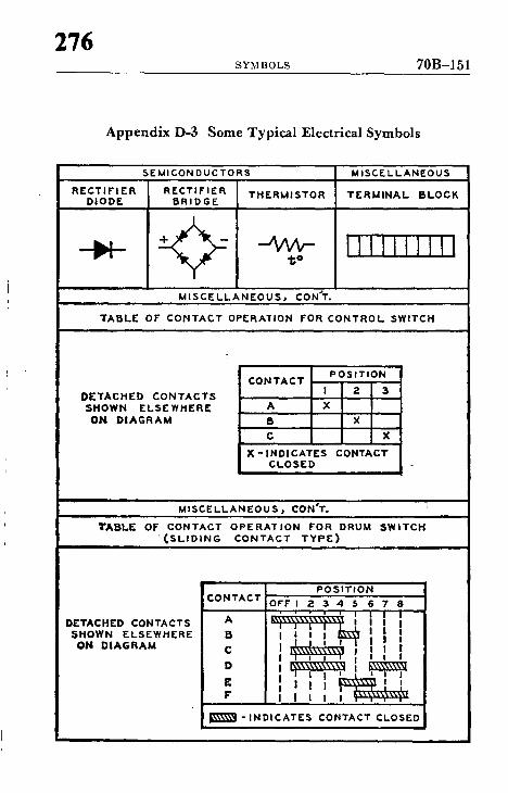
276 SYM BOLS 70B-151
Appendix D-3 Some Typical Electrical Symbols
SEMICONDUCTORS M I S C E L L A N E O U S
R E C T I F I E R R E C T I F I E R T H E R M I S T O R T E R M I N A L B L O C K DIODE B R I D G E
1; ° I I I I I I I I I I
M I S C E L L A N E O U S , CON'T.
T A B L E OF CONTACT OPERATION FOR CONTROL SWITCH
DETACHED CONTACTS SHOWN ELSEWHERE
ON D I A G R A M
POSIT ION CONTACT
I 2 3
A X
B X
C X
X - I N D I C A T E S CONTACT CLOSED
M I S C E L L A N E O U S ~ CON'T.
T A B L E OF CONTACT O P E R A T I O N FOR DRUM SWITCH ( S L I D I N G CONTACT T Y P E )
DETACHED CONTACTS SHOWN ELSEWHERE
ON D I A G R A M
CONTACT
A
B C
D
E F"
P O S I T I O N OFF I E 3 4 5 6 7 8
. , I I J i I I I i i i !
I ! i I ~ i i i . I I I T i i . . i ~ II I I I I ~ I I I I I ~ i ~ I i 1 I ' L ~ i 1 i I ! i Ipzsi i~q~l I
I~\\\\~l - I N D I C A T E S CONTACT CLOSED

70B-152 ELECTRICAL EQUIPMENT MAINTENANCE
277
Appendix E-1 Typical Use of Symbols in a Single-Line Power
Distribhtion Diagram
NOTE: This is presented to show use of symbols and not to be construed to indicate recommendations .
~ I T,'! AN$ FOAM[R KVA
• -~ ~e IMP£ IOAHcar ..L..
HEUTRAL TO GROUNDIHG rL.[CTROD r
m AuPs CONTINUOUS , AMPS MOI, I [ NTARy
rU~S[D DI$CONN[CT SWII'¢H ~ AMPS ~INT[RP.UPTING RATING ~|R)
3 OR 4 W l R r - . ~ ~¢ t .AS :S DISTRIDUTIO
,) ~ T R I P CIRCUIT OR[AKrR. ) ~ ZR ~ - - ] [ R __TRIP
- -FRAM[ $lZl~ - - X R ~ tRAM[ SIZ F
..... • ttt , . . . . .
480V D[LTA TO 61Zl[ J / 208Y/ IZO CONTINUOUS
~II[UTRAL TO 1 KVA CON'rACTOR MOM[NTARY GROUNDING __ ~ eMP[,OANC[ ~ ~ AMP5 [L[CTRODI[ ~ I ~
_ _ CLASS I) I) I - - T R I P
• I 1 1 ) - * " ' " ' * , . , - ° * ' J "LOAD CI[NT[R 20BY/J20 FUS*'I) 5WlTCrl TYP t
LOAD CENT[n CIRCUIT ~RI~AKf.W[ TTP c

Appendix E-2 Typical Wiring Diagram TO 8 U P P L T
r W D ~ I L l A i,,~ I L S L 8 1,8
r 1 ~ ' - - ' ~ : -9~.*FOR L I M I T • II SWITCH £S
' J ' + ° + 1 1 WHEN LIMIT SWITCHES ARC USED - REMOVE JUMPERS BETWC[N Ill I S ~ l l [
TO.ANOT~,ONS"~T~ l a J ~ . . T I -T ~TITp~-I I.~ +3" ,3" +.i" J I , . 0 r ~ - ~ n s .... c I [ / I I / / 1 / + I . . . . . . . . *+ / -J : L ', ,,E,, , L ~ " + ~ ~ . . . . . CT,ON I I I " '
' - - - - ' i I
I z CONNECTIONS
+TOP I S :STATION , ]
TRANSPORU[R LH I o ~ J l l ~ X l
- - - 1 . . . . .
CONNEgTIONS ~ c v I J ~ , t - - ~ u - - , ~ I I | C O N N E C T I O N S 2 - P . . . . . . . E . . . . . . . . . .
L I L2 L~ I [~ . I I ~ . i I ~ I~LL~., t~" FOR MULTIPLI[ LINES ARE FOR LOWER
STOP I i LI LZ L3 3 TRANSFORMER IlIFI I f l SEO CONNECTIONS LJ _ . J t.. __.. .J L - - - - --I ~ TI T2 T3 H2" FOR HIGHER
"]rI[RMINAL~ H | x
T I 1"2 T3 T4
Diagram shows wiring for reversing starter with control transformer.
It,.) - ,4 QO
" , 4
~o I

70B-154 E L E C T R I C A L E Q U I P M E N T M A I N T E N A N C E
279
A p p e n d i x E-3 Typ ica l Schemat ic D i a g r a m
L I
T I
L2 L3
~ I . . . . T
TZ "i"3
RI HI ~ H 4
P FWD R OL. O L
Power and control schematic for reversing starter with low-voltage remote pushbuttons. Forward, reverse, stop connections are shown.


Append ix F-1
T y p i c a l W o r k O r d e r Request Form Work Order WORK O R D E R NO. C R A F T
Request J i l l - - I PLANT DEPARTMENT
DIRECTIONS TO REQUESTER: Complete Section I ONLY. Submit four copies to the Plant Department. Maintain last copy for your files. Prepare a separate request for each job. This request will be returned to you and becomes a work order only when approved and assigned a work order number by the Plant Department. Allow sufficient time for completion. Please T Y P E your request.
I. TO BE COMPLETED BY REQUESTER: Date ........................ / .......... / ............ Summary of work request .................................................................................................................................................................... Location of work: Room(s) .................................................................................................... Building ............................................ Details of work request ........................................................................................................................................................................
Typical work order request form cofisists of five parts - - includes copies for plant ............................................................ department (or plant engineer), data processing, receiving stores, requester, and ............................................................ requester's department. Work to be done is spelled out in detail.
Special time requirement - - Date needed ............ / ............ / ............ Indicate reason ........................................................................ Department .................................................................... Tel. Ext ......................... [ ] Plan attached [ ] Info. attached Authorized signature .................................................................... Title ................................ Approval if required ................................
II. FOR PLANT DEPARTMENT USE ONLY: Date Received ............ / ........ / ............ A. Your request has been [] Approved [ ] Disapproved [ ] Forwarded to ............................................................
for action. Use the assigned work order number when referring to this request.
I

B. Ins t ruc t lons : ....................................................................................................................................................................................
Total Hours Total Labor Material Grand Total Craft
JOB ESTIMATES
Hours $ $ $
Assigned to ......................................... C ra f t ...................................................... [ ] D a y [ ] N i g h t
F o r e m a n - - R e q u e s t e r - -
C . Comple ted per P l a n t ins t ruc t ions? [ ] Yes [ ] No Comple t ed per your reques t? [ ] Yes [ ] No
Can recurrence be p reven ted? [ ] Yes [ ] No P l a n t and Reques t e r note va r i a t i ons ....................................
If yes, indica te ....................................................................
ACTUAL Tot. Reg. Tot. O/T Tot. Equiv. Hrs ....................................................................................................... HOURS USED
D a t e ........................................ Fo reman ' s S igna tu re ............................................ Reques t e r ' s S igna tu re ....................................
I I I . F O R D A T A P R O C E S S I N G U SE O N L Y
Dept. Bldg. Class Category Cause Pay O/T $
I I I I I I I I I I 1
Total Labor S + Total Material $ = Total $
I I I I I I I I I I I I
Work Doseription ~p~uotio, I I I I I I I I I I I I I I I
- - 0
- - 0
0
I o
I
00
P L A N T D E P A R T M E N T

70B-158 E L E C T R I C A L E Q U I P M E N T M A I N T E N A N C E
.283
,|-
Appendix F-2
Ai r Circuit Breaker - - Inspection Record
I~ant Date
Location Serial No.
MFR. Type or Model
Draw ou t C ] Non -d raw o u t ( ~ Sw i t ch board
Rating: V o l t s . _ _ Amps Interrupting Amps
Operation: Manual 17 Electrical ["1 Remote Coutrol [ ]
Volts close ~ AC C~ DC [--] Volts trip
Protective Devices: I n d u c t i o n Relays r"] Direct Tripe [ ]
DATE IN~ECTOtq'$ INITIALS
COqTACr COqDrnON G~d - Surfm Sm~m F W ~ Bum*
O 0 ~ A C T O I B X pmm~m COo~. w ~
D~kWOUT 0 0 ~
Nq;nmm~ (Goad, h d l Lamrksta {kkm Do
~ke A No-Ox~
ARCING ~ I M Jl=.~ C~m md C~mk me
Arc S ~ n o meum
su~em Cond;t~ms
9USItINGS C~en em~ Om~k S ~ Co,~mm
Met~cled r"]
^c~ Dci-I
CL Fuses [ ] TD Setting ~ INST• Setting
ANNUAL INSPECTION DATE INSPECTOR'S INITIALS
POU t tW C ~ & Trip
Lutr ~ ~ ~ ; n .
Lzo~ Conractiom I~gz4orm Coecma T~c~nq
INSULA'nON TES~
11~'T ORERAllON ~ & Tr~p
(No, of Ore,)
EI I~ ' rmCAL LOAD P~k me~,~m Atom
Remarks: (Reco rd ac t i on taken w h e n ind ica ted by Inspec t ion or Tests)
Other Repaint Recommended:
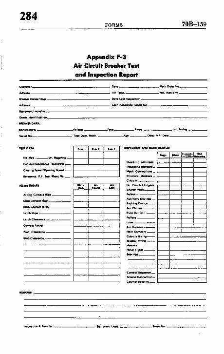
284 FORMS 70B-159
Appendix F-3 Air Circuit Breaker Test and Inspection Report
C u m ~
A d U r ~
Oets I ~ Ordlr No
Air Tlmp RII. Humid:IV
De141 I,Isl trlm0ectmn
I , I l l I n l l ~ i G i 1 ~ No,
Idlflt i I i¢II lon
DATA:
MIP,+fIctWI+
SWill No.
' IIEIT DATA:
I ~ , l~s . , kv. ~ - -
Corltlct R l l i l W l ~ J * i l c r~ l lm _ _
Rlf l r l r ,¢ l , P.F. T i t ~ NO. _ _
AOJUI1MINlI:
Arcing + ¢ t Wipl
Mlm C o . m c l 011=
Mlm Contract W i r e _ _
IJ+ch Wilm
IJtC~ C l l l ~ I m a l - -
Comic+ +rR~ll
C i u r a ~ - -
S t ~ C k ~ t n c e
VOIIIoI Type
l i l t .
A l ~ + II11. h t i l ~ _ _
Otltlt N.P. DItll
I I I IP lCl r l l~ l ANO I&klNI"ENANCI:
Ovi t l l l C l l l l l i l l l l
I r tUl l t inl} M I I t l t l _
1#4¢h. Co~lc t ion l _
Structural Members --
CUbicle
PrL C ~ u ~ l F ,np r l
Shutter Rtl¢l~
RIIIW . . . .
A I ~ + I lllf" V D ¢ ~ t i ¢4141 - -
Rlcking ~ i m - -
~C C~m
81o.+ Out Coil - -
I%+tCN
Linl+ - -
Arc RU~I
Mlin Cemic~l - -
C u b * c l l l W i t i n g - -
l l l l l lkl+ Wit Inll - -
H l l t l r l
l ~ w l l . i g l ~
Imlr lno l
Conwct Sq~,u~rce_
G+OLm,~ Cache*floe_
Counter Ri~ling __
i ~ i o n • Tell I~: EllUil:iTelnt Ul4d: Emheet No,

70B-160 ELECTRICAL EQUIPMENT MAINTENANCE
285
Appendix F-4 Low Voltage Circuit Breaker
Five Year Tests Form
Plant Oate
S.bst~tlon Feeder ~wld Rnodin~
DATA
~fr. ~ Serial No.
Trip Col) Rat£ng - - amps Characteristic Y.~r's. T~me Curve _ _
'Tr1~ Pevico3: Long T£me Delay [] Short Time De)ay [ ] Instanta~-,eou~ Trip r~
?ir~e r~.iay ~pe': 011 Sucker l~shl~t ~'~ Air Bellows [~ Air Orifice ~ Oil OZ'~."£ce [ ]
Sett~ ng~: Other ~ l
LT Delay - A m p s Adjustable Range - - Time Adjustable? Yes ~ No []
ST Delay - Amps Adjustable Range - - Time Adjustable? Yes ~ Ho []
Instantaneous Trip - Amps Adjustable? Yes [] No 0
DATA
~te of Test I:ispectnr' s Inlt£a)s
*~S FOU:~D TEST (Trip Time in S~conds)
Pickup Amps
~HE I)EIAY (As Found.Amp ~-)
~T ?fTMUt) PICKUP (Ad justod.Amps) (~t t IFY Tl~141~ OI[LAy|
TIKE O~t¥ ~ (?r ip ?1me £n $eeonds)
Pickup Amps tzm 8 Ttwe
Short Time
RESETTABLE DELAY (Satisfactory)
• ( . ~ ; rot - - s o c ) . ('rrtpr~d)
7 ~STANTAt~/XfS T~OP
R ~ rks :
LEFT POLE
CENTER RIGHT TIME ~N~E POLE POLF, ~ CURVE
iiUii!iii!!i!i
I"
[!!iiii i!iiiSiiiiiiii ii! !iiiii Recor~ unusual condit, lons, corrections, needed r~pairs, et~. se JTC For~ #219 to record annual br~ker Inspection dotails./

286 FORMS 70B-161
Plant
Locat ion
MFR.
Rating: Vo l ts
Type: Switchboard
Appendix F-5 Electrical Switchgear - - Associated Equipment
Inspection Record Date
Serial No. P&.G No. - -
Y©az Installed
Bus Capacity Amps
1 7 Indoor Metalclad [ ] Outdoor Metalclad
ANNUAL INSPECTION (Disregard items which do not apply)
I-1
DAIE DA]IE INSPECTOR's INITIALS IN~PSCTOR'S INITIALS
1190(]e~ECT SW[TCIE9 O~n ~ Con~-I ~ u r ~ C~ck W~mg C ~ k I n ~ n Cor~t ;~ I n~ l Pa~ l InaCt ion
LuUe ~m* ~ Ml~s. InStructions
E ~ B ~ "15 TUt (~o41tm O 0 ~ E ~ O N S
Oe~ ~ Check I%+c~em ~ A ~
Ir,~u~cet for Crmks or Check Conu,ct S . r e ~
ch~= F ~ , ~ , ' , . CheCk & T~g~ten C o . ~ c t ~ i 1 ~ Pothaa~ For t.AmkJ CheCk f~' E~ror¢lmud ~ A ~ r ~ r ~
H,z~e~ Check Op~|clon
Tim I~lm;on oalga~nl) T~I Mm~, pe~
Ti l l PmsV* METkl£L./~ ~ICIOSUR.ES E,g. S~d.
CkNm CheCk e~ Ol~ningj ~tlmh ~ A Per erae C~rt, M o ~ t ~ & P~a~ent Entnm~ -- R ~ i r O~¢k H~d~ww to* Rust Check fo* ~ O p * , ~
Corro~m Check t.Jghming Arrmtm P~int C, on~ t i~ Check G ~ n d Detllctarl
CheCk Hlla tm's ~1 V ~ t i l I ~ I C~eck Eqpt. O r ~ n d ~ +
METALCLAD BUS & STATION BAI"ff.RY [~I[~slECTI(~S InWect to Com~rm thl~
I nll*Ll~ Q q ~ S+~2~or~l Per k:dic moullrm
CheCk & T ~ m Co~r,*c~,~ ~ n ~ n c ~ +i Pwlo.nl~ f~ ~ TriCk+rig
Tilt Inlulm;on iMegohms)
Remarks: (Rccord act ion when indicatcd by Inspect ion o r Tests)
Recommendations:

70B-162 E L E C T R I C A L E Q U I P M E N T M A I N T E N A N C E
287
Appendix F-6 Transformer Dry Type - - Inspection Record
Plant Date
Location S¢ rial No.
Year Purchased Year Installed Mfr.
kVa Voltage ~ Impedance
Phase Taps
Cooling system: Room Trans. Vent Fan ['----~ Fans
A N N U A L INSPECTION
~A~E NSPECTOfl'S INITIALS
-1ECZ]~IOL LO/~
VOLTAI?~E
Full LOad Volts
DUST ON W I ~ G S M i ~ CoA klct k>n Real~ ccd~ctlo~ C ~
Check.d
Fan O¢~rl~;on
,,, DAlE IN,~PECTOWS i NIT1 AI+S
CrKkl or Ch~ C~sn.rm~
B~URV~T GROU~
¢'h~k Conee~om ~ r c d V Re~seanc~
I~]~PEP.A'n.~E ALARM5 AND "~ICA~ORS
Ope~t~n ~ r ~ ' v
CASE EX~JOR C~rs intact Point Condid~
UQl*I1NG ARREb'lZ~ Check Coenl¢1 k ~ Check SUndeW
Gravity
COMPLETE INTERNAL INSPECTION
Report of Conditions Found:
Cooling System Coil Insulation Other
Description of Work Performed:.
Other Repai~ Recommended:
Shop or Contractor: COSt:

288 F O R M S 7 0 B - 1 6 3
Appendix F-7 Transformer - - Liquid Filled - - Inspection Record
Plant Date
Location Serial NO.
Year Purchased Year Installed. Mfr.
k V s Voltage Taps
Check Type Free Breathing [ ] Conservator [ ] Sealed F " ] Fan Cooled
Phase Wei~t Impedance
Insu la t ing F lu id : T y p e Gal lons
A N N U A L I N S P E C T I O N
DATE DA'F~ INSPECTOR'S INITI AL.~ I NS:PE CTOFCS INITIALS
T ~ - LK~D ~ ~ - LEVEL CrEks e* Chim
N~ml~ Clqenlimm 8 ~ o w
I ~ ' I ; U ~ [ E O 3 M P ~ C, eed - U(~ID LEVEL O~tidn~e
T~md Nerrea, ~ l o w
IEMP' ~U~1UR Addod Fluid H~tMl~l[ nlodln1~
Ft~wt P~nter ELECTRICAL I,O,q)
A, ,m ~ V A O J U M
Sl~Ohn~tRY VOLTAGE I~01CATOR Full L~d Prluum
Loed V ~ u m
GASKEI~ & CASE EX'TERIOR VIEI~m..A'IUI~X DI~d~RS. t.~id LUkl GAUGES. FIL11~S & P*int: Condition l ~ A ~ IJ)[t, RJ F~'
~ t . RIq'd.
Remarks: (Record ac t ion when Inspect ion data or "tests e re out of l i m i t s , e t c . )
[]
Repor t o f Conditions Found:
Description o f Work Performed:
Other Repair Recummended:
Shop or Contractor: Cost:

70B-164 E L E C T R I C A L E Q U I P M E N T M A I N T E N A N C E
289
PLANT
Appendix F-8
Transformer Fluid Test - - Oil
DATE
MANUFACTURER'S S/N
~m
SQq4
Im
a NOTE :
D i e l e c t r l c S t r e n g t h In k¥ ( I n d i c a t e i n Blue)
N e u t r a l i z a t i o n as m$ KOH/Em ( I n d i c a t e in Red)
Readings which p l o t Ln the shaded zone must be r e p o r t e d immedia t e ly to the Eng lnee r l n 8 D iv l s lonp E l e c t r i c a l S e c t i o n .

290 F O R M S 7 0 B - 1 6 5
Appendix F-9 Transformer Fluid Test - - Askarel
PLANT DATE
t4AH~ACTUREP, ' S SIN
NOTE:
D i e l e c t r i c S t r e n g t h i n kV ( I n d i c a t e i n Blue)
Neuttalization as g KOH/~ (Indicate in Red) ~
i i '
¢ : i i
Readings which p l o t i n t h e shaded zone must be r e p o r t e d immedia t e ly to the E n g i n e e r i n g D i v i s i o n , E l e c t r l c a l S e c t i o n .

7 0 B - 1 6 6 E L E C T R I C A L E Q U I P M E N T M A I N T E N A N C E
291
Appendix F-10
Transformer Insulation Resistance Record
P ~ m n t r ~ m
3oo1~: P~mr t ~ s ~ o m s r s o t ~ 0 kVa ~ d t r N t 3 r ~sp~o~t~ vLt~ p r ~ s ~ ~o)+44e o f 2)00 ~o21~ or I ~ h s r . ~ r m d L n ~ , r ~ c r d e d m~d p2olted.
? r I s ~ o r s m r Ser~s2 No. Phase
LooaL~on Z J ~ m ~ ~secl
• patlmmt I ~ l ~ t. ~ s
eZnspee~r ' s ' r ~ - ~ e
,i i~-,7 n . - ~ .
, ",:~, k , , , ',', Jooo l eeo i , ,
' 'N i ' :
-i I .~1
eo 1 ee !
I o i i ,-k
m m m n l u m I l I B I I l l Immmmu i m a m a i l l l l l l i i n d s l ~ - ' l l ' - ' l l m - ' . " j ~ a m i m m i m i i m i m m e l | • i l m H i l U l a l a m l I ~ mm~um i n n a i mmmmmm um
l | ' - - . ' |EG' -B ' - ' - ' - ' - I ~ R m i I I m N m i m m i ~mmmmmmiommmm ~ m m m m m N m m m i Imommmmmmmmmm immnmmimmmmm mml ~ m o m m m m m m m m m l a n u u m m i m m m m m ~ n m m m m m m m m n m m ~ m m m m u n m i m m m i 1~ mum imalmmlmi imll
mmmmmmmmmmmmmmm imm m n Imo mum l N i l N a i m •
J N i t I J i l l l e l i Im i i i i i i l l Jl ~ a n n i m m m m m n m m m l n i i m e • lmmlmi mmm wi me
immmlimummmmamn iimmmimmmmmumml Imummmmmmmmmmmmm
m imimm~mm mini • m m u • i nn nm l im i n I i J i J I I i i I m I i l i I I =
I I , ," ! I 'J • , i F mm
) I • i i : i _ I I I I I
- - i i
l ~ i i m l I I ' " I N
' i l i i l i lm I 1 1 I I I
i l . . . . , , i i l I I I i I I n r J ~ , , i ] nm
• l inl l I I l ; l
n u m m m l i n J i l U i I i ~ l i N i i I a m | mmmmmmmmi lmn mmn mm i l n u m m n i m w
| i i i i i E G i l I i U i I n m l m u m m m e u H m m l n m J m l l n m m m
I N E N - ' I B I I i l l l J l i i l I l m m m I u n J m l I I m / n l l ~ m m l l -_.-.-_.m_.um
| l i I l I i l i l l i mmmmmmmmmmn mlnp
noi e m i l i o i m i m mmai I m g g i H g g l i g i g i m g i g l
18- '- ' - ' - ' - ' - ' - ' I l a i m o l o m m o
i m i m m i n i m n ~ i l m l l i n i l m

292 FORMS 70B-167
Appendix F-11 Battery Record
~lGt Gill P, lot
S~. G,. Cell T*mu. VOI .
Vmt~ Ch~k ~ec*f~ SmofPc
Ckum ~ C~l C,,~IV v~ . C~ Grf,~w
1 31
2 :D
3 33
4 :~
5 36
e 38
; 37
8 38
g 3O
sO
s~ 42
13 ,43
14 44
16 44
17 47
10 44
19 ,IO
2O SO
21 51
S3
~4 54
27 87
3O 6O
211 '6O
3O 3O
vo*~ ~urreAI
e*Tuwv Room Con~t~on
QlJl Tm '~ : I 16
3O 46 eo

70B-168 ELECTRICAL EQUIPMENT MAINTENANCE 293
Appendix F-12 Insulation Resistance - - Dielectric Absorption Test Sheet
Power Cable No,
l~-, ~- [] ,~,D ,,-O I~ ~]., n,..,, []
~ ~ N a , u e ~
I-
B ~
~ m J
CONNKTO~
0 "
I~1 urn.
D A T A - M [ O O H M S
UNR
DA~ S N U t ~ W ~
,/.% ~ N ~
ro Jzlou,lw
Now o m ~
~ re, iT
~¢~TAG4

294 F O R M S 70B-169
Appendix F-13 Cable Test Sheet
CONPkO 1B1 t~.&nog I~E IB'T:AGI~TNICE D . ~ 0,~0
B ~ o k y ( ~ , ter=o.3 oR~. kV l ee . mm.]
Ar~
I IlO. (:Olll.
L~
nw_l~
i1~1~ t I~l IN ~k'tO~f TIS"I kV
14AX. 115IKV vmn4L'nl LY
~ I . O d ) Z . A ~ l - m
a l o f t
0NE Nl1~1~ @ Z.S kV 1000 HKOH~ ~mee,
A U 1 1 ~ T m 0F K~L I~kYJUlD Vg~YmS ~ 1 1 q ~ kV
DA1T m NO. ~ t 1 1 ~ . . . . °C "/.HUN
10. Vlff~IHEII
1~ m m
, I ~ ~ I 1 0 . _ _ IIEIIED I~ SI'T I L

70B-170 E L E C T R I C A L E Q U I P M E N T M A I N T E N A N C E
295
Appendix F-14 Insulation Resistance Test Record
Date
Scope: Dle lec t r l c Absorptic~ vlthc~._._...~£ Temperature Correc¢lon
Apparacum
I n e t ~ , n c Used
Cond i t i on 10:1 H in . P a t i o
Dlmseroue . . . . Less than 1
Poor Less than 1.5
Quest ionab le - - - - 1 . 5 to 2
Equipment Temp. Ambient Temp.
P o l a r i z a t i o n Index No.
F a i r . . . . . 2 co 3
Good . . . . . . 3 to 4
E x c e l l e n t - - -Above 4
T t ~ e In Hlnutes .25
Phase I
~ P h i 2
o Ph~ 3
Phase I - 2
~ Phase 3 -1
.50 1 2 3
- P l o t the l o v e s t group read ing on graph
4 5 6 7 8 9 10
o o
Tested by

296 F O R M S 70B-171
Re~e~ces
I E E E l~bl~cat~em ~Io. ~3
Date
Apparatus
Te~t ~nd~t~ nns:
EAet A s s o c i a ~ F.~lp,~nt Xnclu~ed in Test
Appendix F-15 Insulation Resistance Test Record
Rotating Machinery .~co~e
Dielectric Absorption,- Tesa~rlture Correcl:ed
I C ~'mc~nes 1 ~ KVA or ~orm l DC ~ a e ~ s 1~0 ~4 or ~oro
V o l t ~ Rat~u~
1~.'~.ndLnl: Gzou~dL~g ~ Test 14ade - - Hours L ~ r b ' ~ u ~
L~b~.ent Temperature °F R e l ~ v ~ I~mid~t.y ~ ~ ~e~t}~er
~Lpmen~. Temper~ur~ l l ~ C b ~ a ~ .
Instrument Ran~ Vol~al[~
T ~ t B a ' l ~ :
oo,,o,,oJ ! I ! i ! ! !.i I I ".,.,~,.. I' ~ " i I ~ I t ~ I ' I I
I ,ooo | l IIiO
|oQo i
ete .
" " ~ ~ *~i • ee i i
. I . I I i
"'iiT.. il ~ i i l l : : i i l i i i 11,,
. . . . ! ~ I I I
i ! i ii i ,. I ' ! I I I I I I • ili !} ~I;:
;i , ; i ! i i , I ; ! i I i L
• ' ! i t t I I I
p O l ~ . t , ~ t J . O I r ~ g o . ( 1 0 / 1 ~ . n , k t l o )
l i l ~ L I 1 ' ' ! 1 1 1 ! ~ 'i I
!! !!If'''' ' ili ~i i i i i i i i l , ! ! ! ~ i ! i I , , , f I l l , , i i
I ' ! ! : i i I i I I l l ' l i l i l l i ' ' I I I
' , 1 1
i i i . , * ' i l l , i , i ,
T e s t ~
I I ~ m r k ~ i s