130-01 Operations - University of...
114
Refraction Technology Refraction Technology, Inc. 130-01 Operations Startup 10/30/2008 CPU 2.9.1 This REF TEK manual provides startup and basic operating procedures for the 130‐01 and its related family of products. Internal cable drawings are also provided along with guidelines for initial communication and installation.
Transcript of 130-01 Operations - University of...

Refraction Technology
Refraction Technology, Inc.
130-01 Operations Startup
10/30/2008
CPU 2.9.1
This REF TEK manual provides startup and basic operating procedures for the 130‐01 and its related family of products. Internal cable drawings are also provided along with guidelines for initial communication and installation.

Refraction Technology
Refraction Technology, Inc. ii
Copyright© 2008 Refraction Technology, Inc.
All rights are reserved. No part of this manual may be reproduced, copied or transmitted in any form outside the approved recipient’s organization without written permission from Refraction Technology Inc.
Printed in USA. Refraction Technology 1600 Tenth Street Suite A Plano, Texas 75074 Tel: 214-440-1265 Fax: 972-578-0045 www.reftek.com

Doc-1301-Ops Rev 2.9.1 10/30/08
Refraction Technology, Inc. iii
About this manual:
This 130-01 Startup manual provides a detailed overview of the command line operations and setup of the 130-01. It covers the following broad operational topics:
Overview
Connections
Operation with PFC
Port Settings and Power Considerations
Modem Setup
Periodic Maintenance
Logfile Example

130-01 Operations
Refraction Technology, Inc. iv
Revision History:
Revision Date Reason for change Pages
0.1 03/14/08 Initial release All A 10/26/04 Update to new format All B 03/01/05 Update to new A/D and Case All C 06/30/06 Update SM sections All D 01/09/07 Updated for new PFC version All E 04/08/08 Converted to WORD templates All
CF Card Replacement:
Due to the large variability of CF cards available on the world market and the resulting problems with compatibility due to memory layout, signal structuring and power requirements, Refraction Technology cannot guarantee a CF card will work in a REFTEK data recorder unless it is sold through REFTEK itself. REFTEK ensures compatibility through communications with CF manufacturers and rigorous in-house testing. Some CF manufacturers refuse to provide adequate information or factory controls to ensure that the product being sold today is the same as the product sold earlier under the same part number. CF cards not purchased from REFTEK may work at one temperature but not at another, or may fail all together.

Doc-1301-Ops Rev 2.9.1 10/30/08
Refraction Technology, Inc. v
Software Version:
Current software and documentation is available on our web site. Some early units may require hardware modifications to use the latest software. Contact REF TEK if you have any queries on the compatibility of your unit(s) and the current software release.
Firmware Update:
To update firmware from the FTP site
1. Login to our FTP site at: ftp.reftek.com/pub as: User name: Anonymous Password: Your E-mail address
2. Find the 130 firmware at ftp.reftek.com/pub/130/cpu/prom.
3. Download the zip file of the most recently released firmware version. Update firmware:
Updating firmware in a 130 DAS requires the presence of a firmware file on an installed Compact Flash device.
1. On power-up, the 130 checks the Compact Flash for the presence of ‘main.s3’ in the root directory.
2. If the ‘main.s3’ file is present on the Compact Flash, the 130:
a. Reads the file.
b. DELETES the file.
c. Re-programs the internal flash memory.
Note: DO NOT DISTURB THE UNIT DURING THIS PROCESS. Follow these steps to update the firmware of a 130 DAS:
1. Unzip the ‘main.s3’ file from the downloaded zip file of the most recently released firmware.
2. Copy the desired firmware image to the root of the Compact Flash as ‘main.s3’ using a PC with a Compact Flash reader or ftp into the 130 DAS, with a Compact Flash installed, in binary mode.
3. With the Compact Flash with the main.s3 image installed in the 130 DAS, issue a reset command.
130-01 Operations
Refraction Technology, Inc. vi
(a) If you are at the 130 DAS:
1. Issue a Reset command from a PDA running PFC_130 or Physically disconnect and reconnect power to the unit.
2. Observe the LCD for the following messages: READING DISK DO NOT DISTURB WRITING FLASH DO NOT DISTURB
3. The 130 DAS resets and returns to normal messaging. (b) If you are remotely connected to a 130 DAS via telemetry mode:
1. If you are connecting remotely by a TCP connection: a. First connect b. Discover the unit c. Acquire status
2. Issue a reset command from the Status screen.
3. Delete the unit from the Station List screen.
4. Wait at least 5 minutes. 5. At the Connections screen (reconnect id using a TCP connection) issue a Station
Discovery again to discover the 130 DAS station. Note: DO NOT DISTURB THE UNIT until the start-up LCD message reappears.

Doc-1301-Ops Rev 2.9.1 10/30/08
Refraction Technology, Inc. vii
Notation Conventions
The following notation conventions are used throughout REF TEK documentation:
Notation Description
ASCII Indicates the entry conforms to the American Standard Code for Information Interchange definition of character (text) information.
Binary Indicates the entry is a raw, numeric value. Hex Indicates hexadecimal notation. This is used with both ASCII characters
(0 – 9, A – F) and numeric values. BCD Indicates the entry is a numeric value where each four bits represents a
decimal digit. FPn Indicates the entry is the ASCII representation of a floating-point
number with n places following the decimal point. <n> Indicates a single 8-bit byte. When the contents are numeric, it
indicates a hexadecimal numeric value; i.e. <84> represents hexadecimal 84 (132 decimal). When the contents are capital letters, it represents a named ASCII control character; i.e. <SP> represents a space character, <CR> represents a carriage return character and <LF> represents a line feed character.
MSB Most Significant Byte of a multi-byte value. MSbit Most Significant Bit of a binary number. LSB Least Significant Byte of a multi-byte value. LSbit Least Significant Bit (bit 0) of a binary number. YYYY Year as a 4-digit number DDD Day of year HH Hour of day in 24-hour format MM Minutes of hour SS Seconds of minute TTT Thousandths of a second (milliseconds) IIII Unit ID number n, nS nano, nanoSecond; 10-9 = 0.000000001 u, uS micro, microSecond; 10-6 = 0.000001 m, mS milli, milliSecond; 10-3 = 0.001 K, KHz Kilo, KiloHertz; 103 = 1,000 M, MHz Mega, MegaHertz; 106 = 1,000,000 G, GHz Giga, GigaHertz; 109 = 1,000,000,000 Kb, KB Kilobit, KiloByte; 210 = 1,024 Mb, MB Megabit, MegaByte; 220 = 1,048,576 Gb, GB Gigabit, GigaByte; 230 = 1,073,741,824

130-01 Operations
Refraction Technology, Inc. viii
Related Manuals:
130-01/3 System Documents Number PDF file
130-01 System Startup Doc-130-Ops 130_startup_01.pdf PFC_130 Users Guide Doc-130-PFC Pfc_130.pdf Data Utilities Users Guide Doc-DataUtils 130_utilities.pdf Archive Utilities Doc-ArcUti ls arcutil.pdf 130 Theory of Operations Doc-130-Theory 130_theory. pdf 130 PFC Release Notes Doc-130-PFCRel 130_PFCRN.pdf 130 CPU Release Notes Doc-130-CPURel 130_CPURN.pdf 130 Command Reference Doc- 130-Cmd 130_command.pdf 130 Recording Format Doc-130-Record 130_record.pdf 130-GPS Manual Doc-GPS-Ops 130_gps. pdf 130-01 Board Documents Number PDF file
RT505 - A/D Board Doc-130-RT505 RT505r.pdf1 RT506 - CPU Board Doc-130-RT506 RT506r.pdf RT520 - Lid Interconnect Board Doc-130-RT520 RT520r.pdf RT526 – Micro Drive/Flash Board Doc-130-RT526 RT526rB01.pdf RT527 - Sensor Control Board (Optional) Doc-130-RT527 RT527rB01.pdf RT535 - Mass Memory Board (Optional) Doc-130-RT535 RT535rB01.pdf Optional Manuals Number PDF file
SNDP Reference Guide Doc-SNDP-Ref SNDPRef.pdf SNDP Installation and Users Guide Doc-SNDP-Install SNDPUser.pdf RTPD Installation and Users Guide Doc-RTPD RTPD.pdf RTP Protocol Doc-RTP RTP.pdf RT_View Users Guide (Part of Data Utilities)2 Doc-RTView RTView.pdf
RTCC Command and Control Users Doc-RTCC RTCC.pdf 130 RTCC Release Notes* Doc-RTCCRel 130_RTCCRN.pdf RT_Display Users Guide* Doc-RTDis RTDisplay.pdf RTPMonitor Installation and Users Guide Doc-RTPMon RTPM.pdf
131A-02/3 3G Triaxial Accelerometer Doc-131A-02/3 131A023.pdf
131A-02/2 3G Biaxial Accelerometer Doc-131A-02/2 131A022.pdf 131A-01/3 4G Triaxial Accelerometer
Doc-131A-01/3
131A013.pdf
131B-01/1 4G Unixial Accelerometer Doc-131B-01/1 131B011.pdf
1 R = Revision level of 130 Board 2 * = Programs are included in the optional REF TEK Command and Control Interface (RTI)

Doc-1301-Ops Rev 2.9.1 10/30/08
Refraction Technology, Inc. ix
REF TEK Support and update notifications
As a valued user of REF TEK equipment we would like to provide the best support possible by keeping you up to date with our product updates.
If you would like to be notified of any REF TEK product updates please spend a couple of minutes to register with the REF TEK customer support team.
To register, either email to [email protected] giving us your name and REF TEK product you currently have or fill out our online registration form at www.reftek.com/registration
Once we register your contact we will only send necessary notifications via email. The same notifications will be shown on our website’s www.reftek.com/support page
Thanks,
Your REF TEK support team

130-01 Operations
Refraction Technology, Inc. x
Contents
1 Overview ................................................................................................ 1 1.1 Introduction ............................................................................................... 1 1.2 Specifications ............................................................................................. 3 1.3 Mating Connectors ...................................................................................... 4 1.4 Purpose of the 130 Broadband Seismic Recorder ............................................. 5 1.5 Standard Faceplate Connections.................................................................... 6
1.5.1 Power connector .................................................................................... 6
1.5.2 Control Connector (Serial) ....................................................................... 7
1.5.3 GPS Connector ...................................................................................... 7
1.5.4 Net Connector ....................................................................................... 8
1.5.5 Channel Input Connectors ..................................................................... 10
1.5.6 Channels 1-3 connector signals .............................................................. 11
1.5.7 Channels 4-6 connector signals .............................................................. 12
1.6 General Recorder Control Considerations ....................................................... 13
1.6.1 General Recorder operation ................................................................... 13
1.6.2 Power Considerations ........................................................................... 15
1.7 Port Settings & Modem Communications ....................................................... 16
1.7.1 Control (Serial) Port ............................................................................. 16
1.7.2 Serial PPP Port ..................................................................................... 17
1.7.3 NET Port ............................................................................................. 17
1.8 Hardware Modularity .................................................................................. 18 1.9 Frequently Asked Questions ........................................................................ 20 1.10 Warranty Statement ................................................................................... 22 1.11 Warranty/Non-Warranty Service .................................................................. 23 1.12 Static sensitive device protection ................................................................. 24
2 Startup ................................................................................................. 25 2.1 Getting started with your 130-01 DAS .......................................................... 25 2.2 Establishing Minimal Hardware Connections ................................................... 26
2.2.1 Install the Compact Flash ...................................................................... 27
2.2.2 Power up the 130-01 DAS ..................................................................... 28
2.3 General GPS Operations .............................................................................. 29 2.4 Using a PDA for configuration ...................................................................... 30 2.5 Check the GPS Status: ............................................................................... 31 2.6 Example configuration Steps ....................................................................... 33
2.6.1 Create a configuration with PFC ............................................................. 33
2.6.2 Format the Compact Flash ..................................................................... 35

Doc-1301-Ops Rev 2.9.1 10/30/08
Refraction Technology, Inc. xi
2.6.3 Start Acquisition .................................................................................. 36
2.6.4 Write Parameters to disk (WP) ............................................................... 37
2.6.5 Load Parameters from DAS Disk ............................................................. 38
2.7 Examples of 130 LCD Displays ..................................................................... 39
3 Serial PPP Communication .................................................................... 41 3.1 Overview .................................................................................................. 41 3.2 Direct PPP Connection ................................................................................ 42
3.2.1 PC Setup ............................................................................................ 42
3.2.2 Adding Remote Access Services (RAS) .................................................... 46
3.2.3 Start Remote Access Service (RAS) ........................................................ 51
3.3 Modem PPP Connection ............................................................................... 53
3.3.1 130-Modem ........................................................................................ 53
3.3.2 DAS Setup .......................................................................................... 53
3.3.3 Setting up the 130 to use the 130-Modem ............................................... 54
3.4 SLM Modem module ................................................................................... 55
3.4.1 Modem features ................................................................................... 55
3.5 Modem configuration .................................................................................. 56
3.5.1 PFC_130 Serial PPP .............................................................................. 56
3.5.2 Data transfer through PPP real-time ....................................................... 58
3.6 PC Communication Setup ............................................................................ 59
3.6.1 130 DAS modem communication ............................................................ 59
3.6.2 Install modem ..................................................................................... 60
4 Periodic Maintenance Operations ......................................................... 63 4.1 Introduction .............................................................................................. 63 4.2 Replacing the Compact Flash ....................................................................... 64 4.3 Connector Assembly & Maintenance .............................................................. 67 4.4 Periodic Maintenance checks ........................................................................ 69 4.5 Replace CPU Battery (130-01/3 and 130-01/6) .............................................. 70 4.6 Disassembly of the 130 for service ............................................................... 71
4.6.1 130-01 Bill of Materials ......................................................................... 72
4.7 Assembly of the 130................................................................................... 76 4.8 Sealing and pressure testing a 130-01 DAS ................................................... 77 4.9 Firmware update options............................................................................. 78
4.9.1 Download firmware from the FTP site ...................................................... 78
4.9.2 Firmware update process ...................................................................... 78
4.9.3 Updating firmware from a Compact Flash™ .............................................. 78
4.9.4 Updating firmware using ftp .................................................................. 79
4.9.5 Updating firmware at the 130-01 ........................................................... 79
4.9.6 Updating firmware via telemetry mode .................................................... 80
130-01 Operations
Refraction Technology, Inc. xii
4.10 To Test the 130 DAS Memory ...................................................................... 81
4.10.1 Overview ............................................................................................ 81
4.10.2 Memory test process ............................................................................ 81
5 Adding or replacing an RT527 .............................................................. 83 5.1 Overview .................................................................................................. 83 5.2 Installation ............................................................................................... 84
5.2.1 Upgrade ............................................................................................. 86
5.2.2 For a new installation: .......................................................................... 86
5.3 RT527 Scope ............................................................................................. 88
5.3.1 Channel Connector Signals .................................................................... 88
5.3.2 Sensor Test Signals .............................................................................. 89
5.3.3 Auxiliary Channels ............................................................................... 89
6 Logfile Example .................................................................................... 91 6.1 Timing examples ....................................................................................... 91 6.2 System information .................................................................................... 95 6.3 Acquisition Information ............................................................................... 98 6.4 Disk Access Information ............................................................................ 100

Doc-1301-Ops Rev 2.9.1 10/30/08
Refraction Technology, Inc. xiii
Figure 1 130 Connectors ........................................................................................... 6
Figure 2 Compact Flash .......................................................................................... 27
Figure 3 LCD Display .............................................................................................. 28
Figure 4 PFC_130 Start ........................................................................................... 30
Figure 5 PFC Control ............................................................................................... 30
Figure 6 PFC Status ................................................................................................ 30
Figure 7 PFC Load Status ........................................................................................ 30
Figure 8 GPS Mode ................................................................................................. 32
Figure 9 PFC New Configuration ............................................................................... 33
Figure 10 New Configuration .................................................................................... 33
Figure 11 PFC Channels .......................................................................................... 34
Figure 12 Channel Details ....................................................................................... 34
Figure 13 Stream Details ......................................................................................... 34
Figure 14 Format Disk ............................................................................................ 35
Figure 15 Set Acq Delay .......................................................................................... 36
Figure 16 Write (WP) .............................................................................................. 37
Figure 17 Load (LP) ................................................................................................ 38
Figure 18 Add Modem ............................................................................................. 42
Figure 19 Have Disk - Modem .................................................................................. 43
Figure 20 Select Generic ......................................................................................... 43
Figure 21 Select Port .............................................................................................. 44
Figure 22 Modem Success ....................................................................................... 44
Figure 23 Phone and Modem Options ........................................................................ 44
Figure 24 Modem Properties .................................................................................... 45
Figure 25 Control Panel ........................................................................................... 46
Figure 26 Make New ............................................................................................... 46
Figure 27 Incoming Connect .................................................................................... 47
Figure 28 Allow Incoming Virtual .............................................................................. 48
Figure 29 Add DAS User .......................................................................................... 48
Figure 30 Add User ................................................................................................ 49
Figure 31 Networking ............................................................................................. 50
Figure 32 Remote Access ........................................................................................ 50
Figure 33 Services ................................................................................................. 52
Figure 34 RAS started ............................................................................................. 52
Figure 35 130 Modem ............................................................................................. 53
Figure 36 PFC Control ............................................................................................. 56
Figure 37 Assign Baud ............................................................................................ 56

130-01 Operations
Refraction Technology, Inc. xiv
Figure 39 Modem Setup .......................................................................................... 57
Figure 38 Send Serial PPP ....................................................................................... 57
Figure 40 Send ...................................................................................................... 58
Figure 41 Add Modem ............................................................................................. 60
Figure 42 Phone and Modem Options ........................................................................ 60
Figure 43 Modem Option ......................................................................................... 61
Figure 44 Detect Modem ......................................................................................... 61
Figure 45 Installed Modem ...................................................................................... 61
Figure 46 New Modem ............................................................................................ 62
Figure 47 Modem Properties .................................................................................... 62
Figure 48 Handle drive ............................................................................................ 65
Figure 49 Install Drive ............................................................................................ 65
Figure 50 Compact Flash ......................................................................................... 66
Figure 51 PTO Connector ........................................................................................ 68
Figure 52 130-01 Boards Stack ................................................................................ 69
Figure 53 130-01/3 Bill Of Materials.......................................................................... 72
Figure 54 Tighten Pattern ........................................................................................ 76
Figure 55 RT527 SCB ............................................................................................. 83
Figure 56 Unbolt 130 Case ...................................................................................... 84
Figure 57 Remove 130 Top ...................................................................................... 85
Figure 58 Stack Screws ........................................................................................... 85
Figure 59 Install O-Ring .......................................................................................... 86
Figure 60 130-Exploded View .................................................................................. 87
Figure 61 Bolt Pattern ............................................................................................ 87

Refraction Technology
Refraction Technology, Inc. 1
1 Overview
1.1 Introduction This section describes operations and maintenance requirements for the REF TEK 130-01 Broadband Seismic Recorder. It includes the following:
An explanation of the general purpose of the 130 DAS units.
Standard faceplate connection functions, pin-out, and associated cables drawings.
General 130-01 DAS control considerations and operation.
Port settings and modem communications.
Hardware modularity.
Frequently Asked Questions about the 130-01. WARNING: A 130 DAS is shipped pre-configured with a default IP address. Be sure to change this address before connecting the DAS to an Ethernet port. WARNING: The 130 DAS uses a 10BaseT Ethernet chip. The 130 DAS Ethernet port will not work when connected to all 100BaseT and some 10/100BaseT Ethernet hubs.

130-01 Operations
Refraction Technology, Inc. 2

Doc-1301-Ops Rev 2.9.1 10/30/08
Refraction Technology, Inc. 3
1.2 Specifications Mechanical
Size: 5.3” High x 7.3” Wide x 13.5” Long Weight: 4.5 lbs. (2 kg) Watertight Integrity: IP 67 Shock: Survives a 1 meter drop on any axis Connectors
Channel Input: PT07A14-19S (2 each for a 6 Channel DAS) Power: PT07A12-4S NET: PT07A14-19P Serial: PT07A12-10P GPS: PT07A12-8S Power
Input Voltage: 10 to 16 VDC Average Power: ~1 W (3 channel, No Communications) ~1.4 W (3 channels, With Communications) ~1.7 W (6-channels, No Communications) ~2.1 W (6-Channels, With Communications) A/D Converter
Type: modulation,256 KHz base rate 24-bit output resolution Channels: 3 or 6 channels Input Impedance: 2 Mohms, 0.002 µFd, differential @ x 32
25 Kohm, 0.002 µFd, differential @ x1 Common Mode Rejection
Greater than 70 db within ±2.5 VDC
Gain Selection: x1 and x32 Input Full Scale: 20 VPP @ x1 0.625 VPP @ x32 Bit Weight: 1.589 µvolts @ x1 49 nV @ x32 Noise Level: ~1 count RMS at 50sps @ x1 Sample Rates: 1000, 500, 250, 200, 125, 100, 50, 40, 25, 20, 10, 5,1 sps Dynamic Range >135 dB Time Base
Type: GPS Receiver/Clock plus a disciplined oscillator Accuracy with GPS: ±10 µsec after validated 3-D fix and locked Free-Running Accuracy: 0.1 ppm over the temperature range of 0º C to 60º C 0.2 ppm from -20º C to 0º C

130-01 Operations
Refraction Technology, Inc. 4
Auxiliary Channels
Inputs: 3 Channels Available on each Sensor Connector Communication
NET Connector: Ethernet 10-BaseT, TCP/IP, UDP/IP, FTP, RTP Serial Asynchronous RS-232, PPP, TCP/IP, UDP/IP, FTP, RTP Serial Connector: Terminal Asynchronous RS-232, 130 Command Recording Mode
Continuous: Record length Time Trigger: A list of record times and lengths Event Trigger: STA/LTA with advanced features including bandpass filter LTA
hold,etc. Level Trigger: Absolute value, user selectable: g, or % of full scale, or counts
including bandpass filter External Trigger: External pulse on trigger input line Recording Capacity
Battery Backed SRAM: 5 Mbytes Flash Disk: 4 Gbytes with two CFII cards 8 Gbytes also available Recording Format:
Format: PASSCAL Recording Format Compliance:
CE
1.3 Mating Connectors Function Mating Connector
Serial PT06SE1210S Power PT06SE124P GPS PT06SE128P NET PT06SE1419S Channel PT06SE1419P
Doc-1301-Ops Rev 2.9.1 10/30/08
Refraction Technology, Inc. 5
1.4 Purpose of the 130 Broadband Seismic Recorder The REF TEK 130-01 DAS units are rugged, portable, and versatile data recorders. The modular design of their hardware and software allows you to reconfigure them for various types of applications, both short- and long-term. Some specific uses include the following:
Collecting seismic data from earthquakes and micro-seismic events in local, regional, and global studies.
Broadband
Aftershock
Active-Source
Micro-Zonation Survey
Site Noise Survey

130-01 Operations
Refraction Technology, Inc. 6
1.5 Standard Faceplate Connections The functions of the standard connectors on the 130-01 Broadband Seismic Recorder faceplate are as follows:
Figure 1 130 Connectors
1.5.1 Power connector Power is supplied to the 130-01 DAS unit through one power connector. Hardware connection shows typical hardware connection for the 130-01 DAS. The following chart details individual connectors and REF TEK cable numbers.
Recorder faceplate connector
Connector and Cable
130 Pin Pin Desc Electrical Desc Voltage Range
Power PT06A12-4P A +12 VDC Input 10-15 VDC Cable: 130-8075 B +12 VDC Input 10-15 VDC C DGND Power Return
D DGND Power Return
or Ethernet/ModemEthernet
GPS
PDA
12V Power
Sensor cable
Sensor cable

Doc-1301-Ops Rev 2.9.1 10/30/08
Refraction Technology, Inc. 7
1.5.2 Control Connector (Serial) The 130-01 DAS unit's SERIAL connector provides general-purpose serial communications. Commonly, a personal computer, such as a DOS-based desktop, laptop, or PDA using REF TEK software is connected here to monitor and control 130-01 DAS operations.
Recorder Faceplate Connector
Connector and Cable
130 Pin Pin Desc Electrical Desc Voltage Range
Serial PT07A12-60 A TX B Output RS232 ±5 Volts B RX B Input RS232 ±12 Volts Serial device C RTS B Output RS232 ±5 Volts Cable(s): 130-8062
Palm D CTS B Input RS232 ±12 Volts
130-8025 E DSR B Input RS232 ±12 Volts F DCD B Input RS232 ±12 Volts1
G DTR B Output RS232 ±5 Volts H No Connect J DGND PWR K PWR Output2 + 5 Volts3
1.5.3 GPS Connector The GPS connector allows an external clocking device, such as the REF TEK 130-GPS Global Positioning System clock. This connector provides power and serial connections to the 130-GPS Receiver via the 130-8015 cable. See the 130-GPS manual for more information.
Recorder Faceplate Connector
Connector and Cable
130 Pin Pin Desc Electrical Desc Voltage Range
GPS (External Clock)
PT06A12-8P A GPS 1Hz Input Pulse 0-5 Volts
B DGND PWR/Signal GND Cable(s): 130-8015 C GPS RX Output RS232 ±5 Volts 130-8015R D DGND PWR/Signal GND E GPS TX Input RS232 ±12 Volts
F PWR 12V PWR 10-15 Volts4 G GPS RST Output Pulse 0-3.3 Volts H PWR 5V 5 Volts5 Default
1 Volts = Controlled by Software 2 Output = Protected by self resetting fuse 3 Volts = Controlled by Software 4 Volts = Controlled by software and protected by a self resetting fuse 5 Volts = Controlled by software and protected by a self resetting fuse

130-01 Operations
Refraction Technology, Inc. 8
1.5.4 Net Connector Communications between the 130-01 DAS and an external TCP/IP and/or Modem occur across the 130-01 DAS unit's NET connector. The cable (130-8004) has two connectors to allow two connections, one for ethernet and one for serial communications.
WARNING: A 130 DAS is shipped pre-configured with a default IP address. Be sure to change this address before connecting the DAS to an ethernet port. Any IP addresses on one of the same subnets, as the 130 DAS unit, may connect using FTP and/or the command socket. However, the 130 DAS unit restricts the external IP addresses from which it will accept connections, to the equivalent of a Class C subnet containing the RTP host. If no RTP host is set for an interface, no connections can be established to the unit from outside its subnet. WARNING: The 130 DAS uses a 10BaseT Ethernet chip. The 130 DAS Ethernet port will not work when connected to all 100BaseT and some 10/100BaseT Ethernet hubs.
This connector also functions as the point of input for the external trigger. It also serves as the point of output for an event detection pulse.
There is also a 12VDC nominal input on this connector to allow for lab setup via Ethernet using only this connector.

Doc-1301-Ops Rev 2.9.1 10/30/08
Refraction Technology, Inc. 9
Recorder Faceplate Connector
Connector and Cable
130 Pin
Pin Desc Electrical Desc
Voltage Range
Net Communications
PT07A14-19P
A TX A Output RS232 ±5 Volts
Modem B RX A Input RS232 ±12 Volts Ethernet 10BaseT
C RTS A Output RS232 ±5 Volts
Serial PPP D CTS A In RS232 ±12 Volts Freewave E DSR A In RS232 ±12 Volts
Cable(s): 130-8004 F DCD A In RS232 ±12 Volts 130-8019 G COM1PWR PWR VDC1 +5 Volts2 H ENET TX+ Output Ethernet3
J ENET TX- Output Ethernet4 K ENET RX+ Input Ethernet5 L ENET RX- Input Ethernet6 M ENETPWR PWR Ethernet7 +12 Volts8 N DGND P DGND R DTR A Output RS232 ±5 Volts S TRIGOUTB Output, Tristate 0-5 Volt
Pulse T TRIGINB Input 0-5 Volt
Pulse U +12VDC Input 10-15 VDC9 V OSC Output, Tristate10 0-5 Volts
1 VDC = Controlled by software 2 Volts = Protected by self resetting fuse 3 Ethernet = Transformer coupled 4 Ethernet = Transformer coupled 5 Ethernet = Transformer coupled 6 Ethernet = Transformer coupled 7 Ethernet = Controlled by software and protected by self resetting fuse 8 Volts = Tracks main input voltage 9 VDC = Alternate main power input 10 Tristate = Controlled by software

130-01 Operations
Refraction Technology, Inc. 10
1.5.5 Channel Input Connectors Both three channel and six channel units have channel input connectors on the faceplate. The three channel unit has a red “sticker” over the (Channel 4-6) connector socket to designate the unit as only a three channel. Signals from an external sensor enter the 130-01 DAS through the channel input connector labeled CH 1 - 3. Six channel 130 DAS units (130-01/6 and 130-02/6) use a second input connector labeled CH 4 - 6. Channel connectors also provide pins for calibration signals to be sent to a sensor.
Note: The 130-01 DAS (Station Info) PDA display will show how many channels are enabled for your 130-01 DAS.

Doc-1301-Ops Rev 2.9.1 10/30/08
Refraction Technology, Inc. 11
1.5.6 Channels 1-3 connector signals Recorder Faceplate Connector
Pin Name Dir Electrical Desc
Voltage Range
Note
Channels 1-3
A Ch1+ In Channel 1 input + ±10 Volts
On All models
B Ch1– In Channel 1 input – ±10 Volts
C Ch2+ In Channel 2 input + ±10 Volts D Ch2– In Channel 2 input – ±10 Volts E Ch3+ In Channel 3 input + ±10 Volts F Ch3– In Channel 3 input – ±10 Volts G AGnd In Analog ground H Pwr 123 Out Sensor Power 10-15
Volts 1, 2, 3
J PGnd - Power ground K CalEn– 123 Out Calibration Enable
active low OC 4, 6
L CalEn+ 123 Out Calibration Enable active high
OC 5, 6
M Center– 123 Out Center Enable active low
OC 4, 6
N CalSig 123 Out Calibration signal ±5 Volts 6 P Aux1 In Aux (Mass Position)
channel 1 ±10 Volts 6
R Aux2 In Aux (Mass Position) channel 2
±10 Volts 6
S Aux3 In Aux (Mass Position) channel 3
±10 Volts 6
T DGND - Digital Ground U Center+ 123 Out Center Enable active
high OC 5, 6
V Sensor ID1 In/Out Sensor ID 0-5 Volts 6 Note: 1 = Tracks main input voltage Note: 2 = Protected by self resetting fuse. Note: 3 = Output on/off controlled by software Note: 4 = Open Collector, pulls to Ground Note: 5 = Open Collector, pulls to + 5 V Note: 6 = Functions provided by Optional RT527 Sensor Control board

130-01 Operations
Refraction Technology, Inc. 12
1.5.7 Channels 4-6 connector signals Recorder Faceplate Connector
130 Pin
Name Dir Electrical Desc
Voltage Range
Note
Channels 4-6
A Ch4+ In Channel 4 input + ±10 Volts
On All models
B Ch4– In Channel 4 input – ±10 Volts
C Ch5+ In Channel 5 input + ±10 Volts D Ch5– In Channel 5 input – ±10 Volts E Ch6+ In Channel 6 input + ±10 Volts F Ch6– In Channel 6 input – ±10 Volts G AGnd In Analog ground H Pwr 456 Out Sensor Power 10-15 Volts 1, 2, 3 J PGnd - Power ground K CalEn– 456 Out Calibration Enable
active low OC 4, 6
L CalEn+ 456 Out Calibration Enable active high
OC 5, 6
M Center– 456 Out Center Enable active low
OC 4, 6
N CalSig 456 Out Calibration signal ±5 Volts 6 P Aux4 In Aux (Mass Position)
channel 4 ±10 Volts 6
R Aux5 In Aux (Mass Position) channel 5
±10 Volts 6
S Aux6 In Aux (Mass Position) channel 6
±10 Volts 6
T DGND - Digital Ground U Center+ 456 Out Center Enable active
high OC 5, 6
V Sensor ID2 In/Out Sensor ID 0-5 Volts 6 Note: 1 = Tracks main input voltage Note: 2 = Protected by self resetting fuse. Note: 3 = Output on/off controlled by software Note: 4 = Open Collector, pulls to Ground Note: 5 = Open Collector, pulls to + 5 V Note: 6 = Functions provided by Optional RT527 Sensor Control board

Doc-1301-Ops Rev 2.9.1 10/30/08
Refraction Technology, Inc. 13
1.6 General Recorder Control Considerations The 130-01 DAS is a microprocessor-based instrument, using an Hitachi SH3 microprocessor. Each 130-01 DAS unit contains a programmable flash memory chip that contains the 130-01 DAS firmware (control code, micro-processor instructions and Xilinx images). Occasionally, Refraction Technology revises the 130-01 DAS firmware, adding features and improving efficiency. In most cases, you can upgrade the 130-01 firmware in your 130-01 DAS by downloading new code via Ethernet. To download new code see “Firmware update options”. Contact Refraction Technology to determine the applicability and advantages of such an upgrade.
In addition to the CPU control code in the 130-01 DAS, the 130-01 DAS requires that you download specific parameter information to instruct it exactly how and when to record data and perform other system functions. REF TEK provides the specific software that instructs the 130-01 DAS how to perform system functions; it is called the PDA Field Controller program (PFC_130) for a PDA device and is documented in the PFC_130 Users Guide (130-PFC-001). REF TEK also provides RTCC software for command and control with a PC or workstation. Also Refraction Technology maintains release notes on its ftp and WWW site.
1.6.1 General Recorder operation Refraction Technology provides PFC_130 and RTCC interface software. Refer to the Command Format Specification part of the 130 Command Specifications for additional help. In all cases, you must use some version of 130-01 DAS control interface software to select parameters. Any such interface must include the following functions:
Setting parameters
Sending parameters to the 130 DAS
Starting data acquisition
The 130-01 DAS collects data based on the series of parameters that you select and download from the control interface. All 130 DAS units have multiple datastream capability, allowing users a vast array of possible parameter combinations.
You may set the following parameters for each datastream:
Which input channel or channels to include
Sample rate
Data format (recording resolution)
Trigger type
130-01 Operations
Refraction Technology, Inc. 14
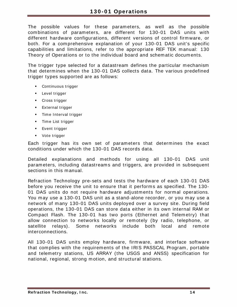
The possible values for these parameters, as well as the possible combinations of parameters, are different for 130-01 DAS units with different hardware configurations, different versions of control firmware, or both. For a comprehensive explanation of your 130-01 DAS unit's specific capabilities and limitations, refer to the appropriate REF TEK manual: 130 Theory of Operations or to the individual board and schematic documents.
The trigger type selected for a datastream defines the particular mechanism that determines when the 130-01 DAS collects data. The various predefined trigger types supported are as follows:
Continuous trigger
Level trigger
Cross trigger
External trigger
Time Interval trigger
Time List trigger
Event trigger
Vote trigger
Each trigger has its own set of parameters that determines the exact conditions under which the 130-01 DAS records data.
Detailed explanations and methods for using all 130-01 DAS unit parameters, including datastreams and triggers, are provided in subsequent sections in this manual.
Refraction Technology pre-sets and tests the hardware of each 130-01 DAS before you receive the unit to ensure that it performs as specified. The 130-01 DAS units do not require hardware adjustments for normal operations. You may use a 130-01 DAS unit as a stand-alone recorder, or you may use a network of many 130-01 DAS units deployed over a survey site. During field operations, the 130-01 DAS can store data either in its own internal RAM or Compact Flash. The 130-01 has two ports (Ethernet and Telemetry) that allow connection to networks locally or remotely (by radio, telephone, or satellite relays). Some networks include both local and remote interconnections.
All 130-01 DAS units employ hardware, firmware, and interface software that complies with the requirements of the IRIS PASSCAL Program, portable and telemetry stations, US ARRAY (the USGS and ANSS) specification for national, regional, strong motion, and structural stations.

Doc-1301-Ops Rev 2.9.1 10/30/08
Refraction Technology, Inc. 15
1.6.2 Power Considerations This section describes current draw, power load, and general power supply considerations for 130-01 DAS units, peripherals, and subsystems.
All 130-01 DAS units operate on nominal 12-volt power (10 to 15 VDC). This range allows a 130-01 DAS unit to be powered from an ordinary lead acid battery that can be charged from either a solar or AC power source.
To ensure continual, uninterrupted power to your 130-01 DAS and peripherals, use a well regulated power supply that can deliver at least 1.25 times the maximum current that the load of your combined system components requires. Be sure to account for the cable resistance (especially if you build your own cables). Power for an external modem is available from the modem port connector (5 VDC or 12 VDC). Also 12 VDC is available on the two channel connectors.
In general, perform the following to ensure a sufficient power supply:
1. Use the specification data and add the maximum current draw for the 130-01 DAS and each peripheral that uses the same power supply to obtain the maximum total current they will draw at any given time then add at least 25%.
2. Check your power supply's specifications to ensure that it can handle this load. The power specifications for 130-01 DAS units are provided for each configuration of 130-01 DAS. Contact Refraction Technology if you require more accurate calculations or other information regarding power considerations.
Solar power setups are frequently used in remote locations and these are available in several capacities that cover the various equipment configurations. Solar power arrays supplied by REF TEK include solar panels, battery charge regulators, and protective safety devices, but they may or may not include the actual batteries.

130-01 Operations
Refraction Technology, Inc. 16
1.7 Port Settings & Modem Communications A 130-01 DAS provides several communications ports. This part describes the available communications ports, and other considerations regarding the use of modems. The ports are:
Serial PPP port
Ethernet port WARNING: A 130 DAS is shipped pre-configured with a default IP address. Be sure to change this address before connecting the DAS to an Ethernet port. WARNING: The 130 DAS uses a 10BaseT Ethernet chip. The 130 DAS Ethernet port will not work when connected to all 100BaseT and some 10/100BaseT Ethernet hubs.
To perform a minimal setup of the 130-01 DAS unit, follow the instructions in section 2 of this manual. To setup port connections refer to the PFC_130 Users Guide.
Note: With a modem, the user can provide a user defined init string that will be sent to an externally attached modem at powerup.
1.7.1 Control (Serial) Port Each 130-01 unit provides two bi-directional, asynchronous serial ports. The first of these ports is accessible at the Serial connector on the 130-01 DAS unit's faceplate. This port has the following primary functions and characteristics:
Function Characteristics
Primary Function Allows command and control input from a peripheral control device such as a palmtop device.
Configuration This port is not user-configured. Recorder software always sets this port to 9600 baud, no parity, 8 data bits, and 1 stop bit.
Hardware Location
This port is accessible at the Serial connector on the 130 DAS faceplate.
Other Features Software controlled output

Doc-1301-Ops Rev 2.9.1 10/30/08
Refraction Technology, Inc. 17
1.7.2 Serial PPP Port Each 130-01 unit provides a second bi-directional, synchronous serial port, accessible at the Serial connector on the 130-01 DAS unit's faceplate. This port, commonly called the Serial PPP port, has the following primary functions and characteristics:
Function Characteristics
Primary Function This port runs the REF TEK Protocol (RTP). RTP provides a full-duplex, packet-orientated, reliable, transport over UDP network connections.
Configuration Using your control interface software, you can set this port's communications configuration as needed. By default, the 130-01 DAS software sets it to 19,200 baud, no parity, 8 data bits, and 1 stop bit.
Hardware Location This port is accessible at the Serial connector on the faceplate. Other Features Software controlled output
1.7.3 NET Port In addition to the serial port, each 130-01 DAS provides one Ethernet port. This port, accessible at the communications Net connector on the 130-01 DAS unit's faceplate, has the following primary functions and characteristics:
Function Characteristics
Primary Function This port performs high-speed transfer of data and status information. It can be used with RTCC to configure the 130-01 DAS, RTPD for data connection and FTP for file transfer.
Configuration The 130 Ethernet port address and mask can be configured using the PFC_130 program running on the palmtop.
Hardware Location This port is accessible at the NET connector on the faceplate. Other Features Software controlled output or input

130-01 Operations
Refraction Technology, Inc. 18
1.8 Hardware Modularity Four boards (*) form the basic REF TEK 130-01 DAS. There are six primary boards for the 130-01. Three of the modules are available on an optional basis. The following table identifies each module.
Basic Set
Brd Description Purpose
* 1 Lid Interconnect Board - (RT520-B01) Power Supplies Lightning Protection
Physical Interface * 2 Compact Flash Board (RT526-B01) Dual Compact Flash
For use with 130-Flash-1G 340 Mbytes to 2 Gybtes For 130-01/3 and 130-01/6 models ONLY! (RT526-B01) Interface Board
(located in the well) Dual Compact Flash
* 3 A/D Converter - (RT505-B05) A/D Converter
Allows 1-3 Channels for 130-01/3 and 130-01/6
24-Bit ADC Channels (3 each board)
OPT 4 A/D Converter -(RT505-B06) Lightning Protection Adds 4-6 Channels to 130-01/6 and 130-
02/6 Input Pre-Amplifier
Digital Anti-Alias Filters OPT 5 Sensor Control Board - (RT527-B01) Monitoring of Mass Position
Re-Centering Command Calibration Commands and Signals Software controlled output
* 6 CPU Board - (RT506) CPU Static Random Access Memory
(SRAM) Battery Backed SRAM (6 Mbytes) Serial Port Ethernet Controller EIDE
7 GPS (RT528-B01) interface board Based on SiRF GPS Chipset

Doc-1301-Ops Rev 2.9.1 10/30/08
Refraction Technology, Inc. 19
The new circuit board dimensions are 10.6 x 4.5 x 0.62 inches (269 x 114 x 1.6 mm). Up to five boards will be stacked together rather than plugged into a backplane. The ADC circuits are shielded and their inputs are isolated on separate connectors from the primary system bus.
Note: *130-01/3 - same as figure above without RT505-B06 A/D Note: ** Optional board Note: For some DAS units an EMI protective shield has been added to make the unit CE compliant. Care should be taken in removal when servicing the unit.
RT526-B01
Well, Disk drive[130-8013]
Case,Top[130-9001]
Cap[130-9002]
Case,Bottom
Seal, Black
Well PCB
[130-9000]
[130-9003]
RT505-B05
RT520-B01
RT505-B06*
RT506-B01
Assembly,LCD[130-8012]
Lid interconnect
A/D PCB
A/D PCB
CPU PCB
Sensor PCBRT527-B01**

130-01 Operations
Refraction Technology, Inc. 20
1.9 Frequently Asked Questions 1. Question: Does any data loss occur if acquisition is turned on and the NET is not
connected?
The damage that occurs depends upon the parameters of the unit. If the unit parameters are set to dump to disk ONLY then there is no effect, otherwise RAM will fill and acquisition will stop. For further clarification see the explanation in the section “NET Port” on page 17.
2. Question: What happens if the Flash drive is pulled from the 130-01 when the LED is RED.
If the LED shows RED the drive is writing data and should not be removed until the LED changes to GREEN. Data loss can result from pulling a drive when the LED is RED. See further explanation in the “Periodic Maintenance checks” on page 63.
3. Question: Can a different sampling rate be used on different datastreams?
- Yes
The sample rate list can be broken into two groups:
Group One: The following rates are only available when recording a single sample rate for all streams: 1000, 500, 250, 125, 50 and 25. Group Two: The following rates may be recorded in any combination within all streams: 200, 100, 40, 20, 10, 5 and 1. Case Description Example of
Selection of a sample rate from Group One.
When the user activates any of the other data streams, the sample rate chosen must be the SAME.
Selection of 125 SPS for Data Stream 1. This means that when Data Stream 2 is activated the sample rate is fixed at 125 SPS and there are no other sample rate choices available.
Selection of a sample rate from Group Two.
When the user activates any of the other data streams, ANY of the group two sample rates can be chosen.
Selection of 40 SPS for Data Stream 1. This means that when Data Stream 2 is activated the choice is selection of any of Group two sample rates (200, 100, 40, 20, 10, 5, or 1).
All six channels run at the same base sample rate at this time.
4. Question: If two datastreams or more at different sampling rates, without a DSP, were set up, would all datastreams default to the sampling rate on datastream one?
It should default to the sampling rate of the LAST datastream, however it always is best to make sure to set all datastreams for the same sample rate.
Doc-1301-Ops Rev 2.9.1 10/30/08
Refraction Technology, Inc. 21
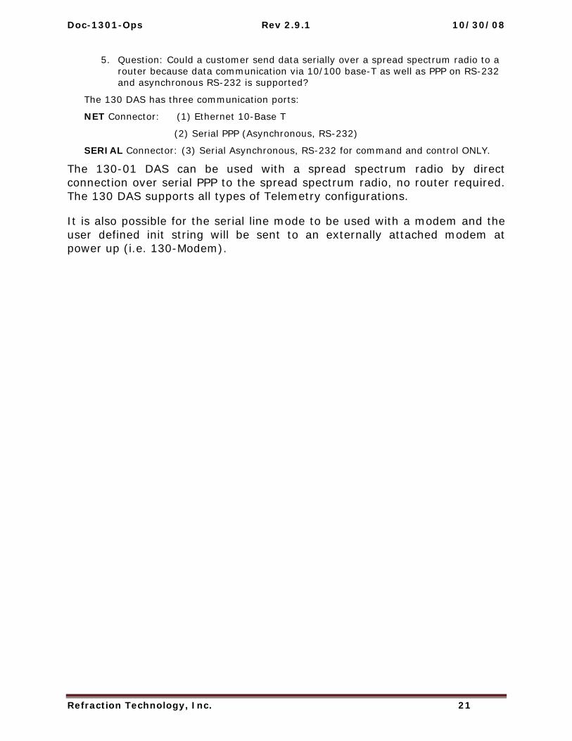
5. Question: Could a customer send data serially over a spread spectrum radio to a router because data communication via 10/100 base-T as well as PPP on RS-232 and asynchronous RS-232 is supported?
The 130 DAS has three communication ports:
NET Connector: (1) Ethernet 10-Base T
(2) Serial PPP (Asynchronous, RS-232)
SERIAL Connector: (3) Serial Asynchronous, RS-232 for command and control ONLY.
The 130-01 DAS can be used with a spread spectrum radio by direct connection over serial PPP to the spread spectrum radio, no router required. The 130 DAS supports all types of Telemetry configurations.
It is also possible for the serial line mode to be used with a modem and the user defined init string will be sent to an externally attached modem at power up (i.e. 130-Modem).

130-01 Operations
Refraction Technology, Inc. 22
1.10 Warranty Statement Refraction Technology instruments are warranted free from defects of manufacture for one year from date of shipment. Any instrument malfunction occurring within this period, except due to improper usage, will be repaired or replaced at our option with no charge for parts and labor. When sending equipment to Refraction Technology for repair, the customer is responsible for freight and insurance charges. Refraction Technology will pay the standard freight cost to return repaired instruments to the customer. (See Warranty/Non-Warranty Service for equipment return instructions.)
In the event Refraction Technology supplies other manufacturers’ equipment with systems, this equipment will have the same warranty as stated above provided the Refraction Technology nameplate is on the equipment; otherwise, the equipment will carry the warranty of the original manufacturer only.
It is the policy of Refraction Technology to continuously upgrade its DAS software. As new software versions become available, they will be supplied to the customer at no charge for two years. After that, upgrades will be available at a nominal charge. However, Refraction Technology is not responsible for any incompatibilities that may arise between new software and obsolete instrument models.
Doc-1301-Ops Rev 2.9.1 10/30/08
Refraction Technology, Inc. 23
1.11 Warranty/Non-Warranty Service The customer must obtain a Return Material Authorization (RMA) number from Refraction Technology before returning any equipment. Do not return any REF TEK supplied equipment without first obtaining an RMA number.
The following policy is applicable for warranty/non-warranty equipment when a problem is encountered.
Contact Refraction Technology, by a means that is listed below, to obtain an RMA number.
Refraction Technology, Inc. 1600 Tenth Street, Suite A Plano, Texas 75074 USA Voice: 214-440-1265 Fax: 972-578-0045 EMAIL: [email protected] FTP: ftp.reftek.com WWW: http://reftek.com
1. Supply the indicated information at time of contact. Description of Problem Type of Instrument Model No. Serial No.
2. Package the equipment safely, preferably using the original packing materials. Include the RMA on the outside of the shipping container, a return address where the repaired equipment can be shipped and a contact telephone number.
Note: It is advised to use a shipping company that can provide a tracking number.
3. Ship the unit to the this address, freight prepaid: Refraction Technology, Inc. 1600 Tenth Street, Suite A Plano, Texas 75074 USA

130-01 Operations
Refraction Technology, Inc. 24
1.12 Static sensitive device protection WARNING: All REF TEK circuit boards are Static Sensitive and appropriate handling is required to protect each board from damage due Static discharge.
1. Please insure that when handling REF TEK circuit boards, the handler and the work bench are grounded. This is usually done via a grounding mat on the bench, which is ultimately grounded to the building ground and also attached to the handler.
2. When shipping individual boards they must be wrapped in anti-static protection, either anti-static bags or boxes. REK TEK can supply these if requested.
3. Failure to protect against static increases the chance of boards being damaged and may void REF TEK warrantee.

Refraction Technology
Refraction Technology, Inc. 25
2 Startup This section provides information on the following topics:
Getting started with the 130-01 DAS and quick power up.
Minimum hardware configuration.
Quick start procedures to familiarize a new user with the system.
2.1 Getting started with your 130-01 DAS This introductory material provides the following:
A brief procedure to establish minimal hardware connections for the recorder in order to perform an initial system power-up.
External cable list.
Minimum hardware connection and power-up.
A procedure to specify an abbreviated set of operating parameters, start and verify data acquisition, and save collected data to a file.
These instructions do not provide you with the detailed comprehensive information you need to prepare your recorder for field deployment and ‘real’ data collection. The complete process to establish all hardware connections, select and implement parameters, and perform data acquisition is only outlined in this section for rapid familiarization.

130-01 Operations
Refraction Technology, Inc. 26
2.2 Establishing Minimal Hardware Connections These instructions cover the hardware and connections needed to perform the recorder operations described in the rest of this section.
To perform the system power-up, you need the following hardware:
A 130-01 DAS.
A personal computer; either a PDA, laptop, desktop, or other appropriate control interface, including a dumb terminal.
An external 12 volt power supply; you can use a 12 volt car battery.
A cable to connect the control interface to the recorder (you can use a 130-8262 with a Ruggedized PDA).
One cable to connect the power supply to the recorder (if you are using an Auxiliary Power Subsystem, you can use a REF TEK PT07A12-4S connector with a power cable).
Note: A sensor is not required for this exercise as the noise pick-up at the open input channel connector is sufficient. If you do have a sensor you must make the channel connections as described in the manual for your particular type of recorder and sensor.
Assuming you have obtained or made up all the required cables, proceed to make the following hardware connections:
1. Install the 130-GPS with a clear view of the sky. WARNING: DO NOT install the GPS at the top of the pole or antenna.
2. Secure the appropriate cable from your PDA or PC control interface to your recorder. In most cases you’ll connect the 130-8025 cable connector to the SERIAL connector on the recorder and secure the other end of that cable to the serial port of your PDA control interface.
3. Secure the PT06A12-4S connector on your external power cable to the POWER connector on the recorder. Secure the other end of the power cable to your 12 volt power supply so that connector pins A and B are both are at +12 volts and pins C and D are the return lines.
4. Secure the PT06A14-19S connector from each sensor cable (2 each for 6 channel recorder) to each channel connector on the case top.
5. Secure the PT06A12-8S connector of the 130-8015 cable for the GPS to the GPS connector on the case top.
X

Doc-1301-Ops Rev 2.9.1 10/30/08
Refraction Technology, Inc. 27
2.2.1 Install the Compact Flash 1. Remove the well cover from the 130-01 DAS as shown below.
Figure 2 Compact Flash
2. Remove the Compact Flash from the 130-Flash kit. Note: Remember to hold the Compact Flash only by its edge as shown below.
3. Install the Compact Flash as shown above.
4. With the Compact Flash in position in the guide rails, lightly press the drive, as shown below, to lock into position.
Note: The 130-01 DAS is not shipped with the Compact Flash installed. ONLY remove the Compact Flash by holding the silver tape to prevent damage to the drive.

130-01 Operations
Refraction Technology, Inc. 28
2.2.2 Power up the 130-01 DAS 1. Power up the PDA device.
Note: Since the PDA unit has RAM, it can potentially open to the screen it was last displaying when it was last powered-down. Reset the PDA to the PFC_130 icon by touching the Home button on the PDA.
2. Turn on the supply to apply voltage to the 130-01 Recorder and to your control interface.
Note: Wait at least 20 seconds and the LCD display should display the following:
Figure 3 LCD Display
Unit ID
FirmwareVersion
FirmwareDate

Doc-1301-Ops Rev 2.9.1 10/30/08
Refraction Technology, Inc. 29
2.3 General GPS Operations When the host 130 receives power the GPS:
1. Supplies +12 VDC to the GPS clock.
2. Issues a reset to the 130-GPS/01.
3. Sends a message to the GPS telling it to go to continuous mode.
4. Sends a message telling the GPS to go to NMEA mode and to output the “GPRMC” and “GPGGA” message once per second.
Once the GPS has locked (per GPRMC-valid bit) the 130:
1. Compares the 130 time to GPS UTC time.
2. Begins phase locking for 30 seconds.
3. Uses the 1 Hz from the 130-GPS/01 to start and stop a counter to record the internal high-precision oscillator.
4. Uses the difference between the value from the 1st second and the value from the 30th second to determine the rate of drift of the oscillator.
5. The 30th value is also used to determine the phase error of the internal 1 Hz.
6. The oscillator is voltage-controlled and an adjustment is made to the controlling D/A value to zero out the oscillator drift, and also to correct for oscillator phase error.
In sleep mode the 130-01:
1. Puts the GPS into binary mode
2. Then into Push-to-fix mode (via serial commands), at which point the GPS will go to sleep.
Note: The GPS is still powered from the 130-01 but is drawing < 1 mA of power. The 130-01 will stay asleep until reset by the 130-01, or until it wakes up to check ephemeris data.
3. The GPS awakens itself it is only for about 3-4 seconds of time approximately once every 18 minutes to check ephemeris.
The 130 will awaken the GPS and repeat the above phase-locking algorithm every 20 minutes.
At initial power-up the 130-01 will leave the GPS on for approximately 15 minutes to do continuous phase-locking and oscillator adjustment.

130-01 Operations
Refraction Technology, Inc. 30
2.4 Using a PDA for configuration
1. Using the PDA device, open the PFC_130 program.
Figure 4 PFC_130 Start
2. Select 130 as the Mode from the pull-down menu.
3. At the Main PFC menu tap the Control window to establish a connection.
4. A connect to DAS menu will display initializing the connection to the DAS.
Figure 5 PFC Control
5. Tap the Status window to check the current status of the 130-01 DAS.
Figure 6 PFC Status
6. Two more screens will open to verify and load status information.
Figure 7 PFC Load Status
Doc-1301-Ops Rev 2.9.1 10/30/08
Refraction Technology, Inc. 31
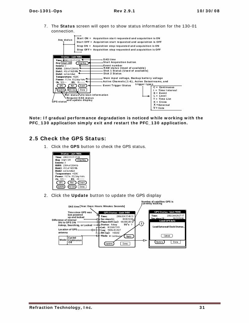
7. The Status screen will open to show status information for the 130-01 connection.
Note: If gradual performance degradation is noticed while working with the PFC_130 application simply exit and restart the PFC_130 application.
2.5 Check the GPS Status: 1. Click the GPS button to check the GPS status.
2. Click the Update button to update the GPS display
Request DAS statusVersion information
Event numberRAM status (Used of available)Disk 1 Status (Used of available)Disk 2 Status
GPS status
Start Acquisition button
Main input voltage, Backup battery voltage
and update display
Active Channels (1-6), Active Datastreams, and
Net status
DAS time
C = ContinuousI = Time IntervalE = EventL = LevelT = Time ListK = CrossX = External
Start ON = Acquisition start requested and acquisition is ONStart OFF = Acquisition start requested and acquisition is OFFStop ON = Acquisition stop requested and acquisition is ONStop OFF = Acquisition stop requested and acquisition is OFF
trigger types
Acq status
Event Trigger Status
V = Vote
2
DAS time
Time since GPS was
up and lockedlast powered
Difference of internal1Hz to GPS 1Hz
Cycled
Asleep, Searching, or Locked
Location of GPSantenna
Number of satellites GPS is
[Year: Days: Hours: Minutes: Seconds]currently tracking
ContinuousOff
Mode:
130-01 Operations
Refraction Technology, Inc. 32
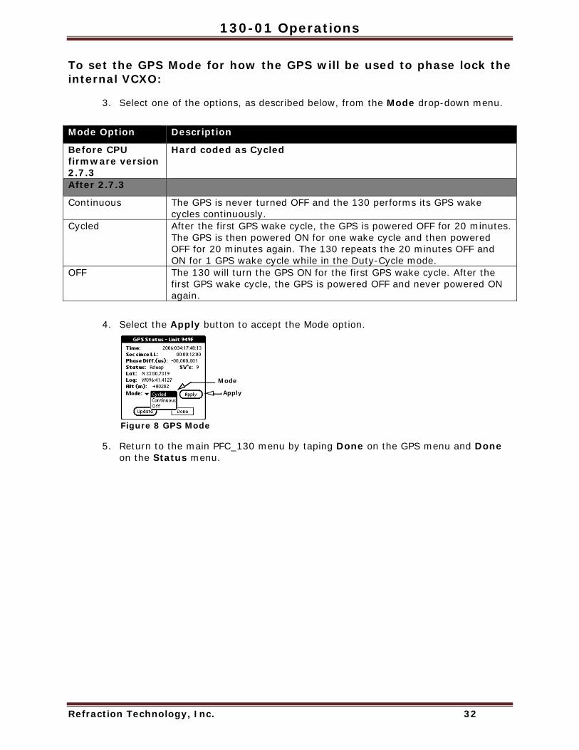
To set the GPS Mode for how the GPS will be used to phase lock the internal VCXO:
3. Select one of the options, as described below, from the Mode drop-down menu.
Mode Option Description
Before CPU firmware version 2.7.3
Hard coded as Cycled
After 2.7.3
Continuous The GPS is never turned OFF and the 130 performs its GPS wake cycles continuously.
Cycled After the first GPS wake cycle, the GPS is powered OFF for 20 minutes. The GPS is then powered ON for one wake cycle and then powered OFF for 20 minutes again. The 130 repeats the 20 minutes OFF and ON for 1 GPS wake cycle while in the Duty-Cycle mode.
OFF The 130 will turn the GPS ON for the first GPS wake cycle. After the first GPS wake cycle, the GPS is powered OFF and never powered ON again.
4. Select the Apply button to accept the Mode option.
Figure 8 GPS Mode
5. Return to the main PFC_130 menu by taping Done on the GPS menu and Done on the Status menu.
Mode
Apply

Doc-1301-Ops Rev 2.9.1 10/30/08
Refraction Technology, Inc. 33
2.6 Example configuration Steps
2.6.1 Create a configuration with PFC Create an example configuration having 3 channels at 100sps to one datastream using the disk as a destination for the data:
1. Create a new configuration for the 130-01 DAS starting with the New menu.
Figure 9 PFC New Configuration
2. Create and name the new configuration as “Test”.
3. Tap OK to create the configuration and return to the Configuration Manager Menu.
Figure 10 New Configuration
4. Edit the 130-01 DAS configuration, by tapping the Edit button.

130-01 Operations
Refraction Technology, Inc. 34
5. Activate 3 channels by tapping the Edit Channels button and entering details for each channel from the Channels Details screen. Tap each channel to activate and enter parameters.
Note: Entering an experiment name will cause it to appear in the Status/Control banner in PFC versions 1.3.2.01 or later.
Figure 11 PFC Channels
Channel Configuration Details
Figure 12 Channel Details
Edit Streams
6. Tap Streams to enter Stream details and set the data destination to disk (D).
Figure 13 Stream Details
7. Set the record length to be 300 seconds and leave time as default.
8. Change to the Configuration Manager menu and save the configuration.
9. Send the parameters to the 130-01 DAS by using the Send to DAS command from the Configuration Menu.
ConfigurationStation MemoExperiment Memo
Channel parameters
Stream parameters
Auxiliary datarecording parameters [1]
Auto mass centering
Sensor test signalparameters [1]
signal parameters [1]
Disk Ethernet Serial

Doc-1301-Ops Rev 2.9.1 10/30/08
Refraction Technology, Inc. 35
2.6.2 Format the Compact Flash 1. Format the Compact Flash using the following menus.
Figure 14 Format Disk
2. Tap the Format Disk menu on the Control menu.
3. Select the Disk #: to be formatted.
4. Select the Start button to start the format or the Cancel button to cancel the format and return to the Control menu.
5. Confirm the format by selecting the OK button.
6. When the format is complete the submenu displays Completed or Error.
7. Select the Done button to return to the Status menu.
4

130-01 Operations
Refraction Technology, Inc. 36
2.6.3 Start Acquisition 1. Check that the GPS has locked or the 130-01 DAS has the correct time.
2. Turn on acquisition by tapping Start Acq next to the acquisition line on the PFC Status menu.
3. If a delay is desired enter a delay time or approve with the OK button.
Figure 15 Set Acq Delay
4. After some period of time (5 minutes or more) stop acquisition on the 130-01
DAS.
Start OFF = Acquisition start requested and
Stop ON = Acquisition stop requested and
Start ON = Acquisition start requested and
Stop OFF = Acquisition stop requested and
acquisition is OFF
acquisition is ON
acquisition is ON
acquisition is OFF

Doc-1301-Ops Rev 2.9.1 10/30/08
Refraction Technology, Inc. 37
2.6.4 Write Parameters to disk (WP) The Write Parameter (WP) command causes the DAS to save the current user-accessible parameters to each disk currently installed in the DAS for later use if necessary.
Note: The parameter file is always saved with Acquisition ON. To write a parameter file from the DAS to each disk:
1. Select the DAS LP/WP button.
Be sure the Acquisition is ON.
2. Select the Write button to write the DAS parameter file.
Figure 16 Write (WP)
3. Select the OK button to approve the write operation.
Note: It is also possible to Write or Load a parameter file during the DAS configuration operations by using the DAS LP/WP command on the configuration menu.
WriteParameters

130-01 Operations
Refraction Technology, Inc. 38
2.6.5 Load Parameters from DAS Disk
The Load Parameter (LP) command causes the DAS to look for a file named 130 (UNIT_ID.CFG) on the disk and load the first one it finds. If this file is not found then the DAS will search for a file named 130_0000.CFG.
To Load a parameter file from a DAS disk to the DAS:
1. Select the DAS LP/WP button
2. Select the Load button to load the DAS parameter file.
Figure 17 Load (LP)
3. Select the OK button to approve the load operation.
Note: It is also possible to Write or Load a parameter file during the DAS configuration operations by using the DAS LP/WP command on the configuration menu.
LoadParameter

Doc-1301-Ops Rev 2.9.1 10/30/08
Refraction Technology, Inc. 39
2.7 Examples of 130 LCD Displays LCD Display
Initial power up LCD
RAM Used Kb out of Total
Compact Flash Used MB out of Total
Date, Time and Temperature
GPS status
Position
Power status of power to the 130 and battery backup power. Acceptable Range: 10-15Volts Backup Range: 2.2-3.6 Volts
Acquisition Status
Stream Indicator: C = Continuous L = Level I = Time Interval E = Event T = Time List K = Cross X = External V = Vote
FirmwareVersion Date
Firmware Unit ID
FirmwareVersion Date
Firmware Unit ID
Used MB Total Available Mb
Date Time
Internal temperature
GPS Status
GPS Position
Main powerBattery backup power
Requested State Actual State
Event Count Stream Indicator---- Inactive
elsetrigger type


Refraction Technology
Refraction Technology, Inc. 41
3 Serial PPP Communication
3.1 Overview Communication between a DAS and a PC can be accomplished by using either:
Direct PPP connection over a direct serial link with a serial cable or serial radio.
Modem PPP connection over a serial link with the 130 DAS Modem or by using the Modem connector on the 130-SM. An optional external modem can also be used with the 130 NET connector for serial communication.
130-01 Operations
Refraction Technology, Inc. 42
3.2 Direct PPP Connection
3.2.1 PC Setup Information File (Generic Null Modem.inf)
REF TEK has supplied a modem information file (Generic Null Modem) that is located in the C:\reftek directory. This file must be resident on the local drive, however, there is no reason to access or make changes to it.
This information file is not needed when using a standard telephone modem. If you do not need to install the Generic Null modem skip the next section.
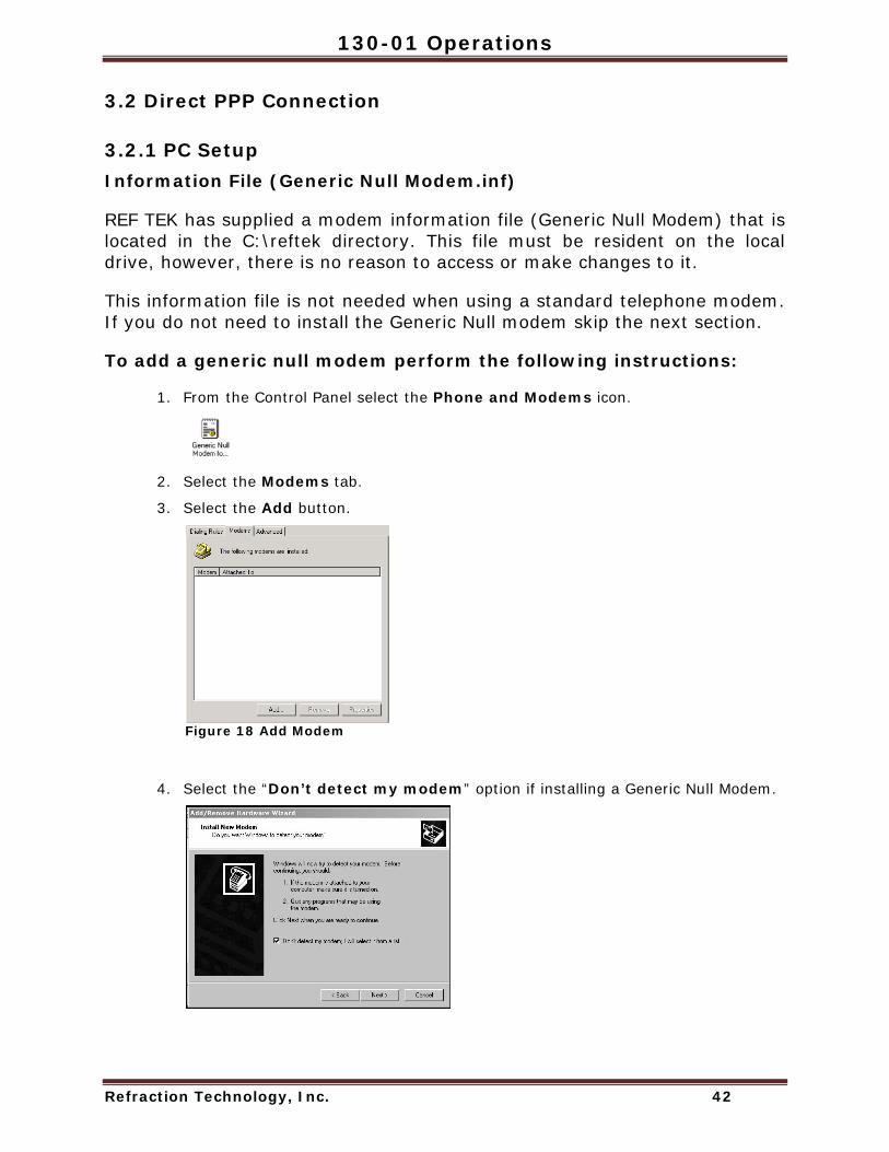
To add a generic null modem perform the following instructions:
1. From the Control Panel select the Phone and Modems icon.
2. Select the Modems tab.
3. Select the Add button.
Figure 18 Add Modem
4. Select the “Don’t detect my modem” option if installing a Generic Null Modem.

Doc-1301-Ops Rev 2.9.1 10/30/08
Refraction Technology, Inc. 43
5. Select the Next> to select the modem from a list.
6. In Install New Modem click Have Disk.
Figure 19 Have Disk - Modem
7. At the Install From Disk window in the Copy Manufacturer’s files from: text
box type C:\reftek
8. Click OK when ready.
9. At the Install New Modem window under Models select Generic NULL Modem.
10. Click Next> when ready.
Figure 20 Select Generic

130-01 Operations
Refraction Technology, Inc. 44
11. At the next Install New Modem window select an available port to use for the modem
12. Click Next> when ready.
Figure 21 Select Port
Note: If the “Digital Signature Not Found” warning appears, select the Yes button and proceed.
13. The Install New Modem window will display Your modem has been set up successfully
14. Click the Finish button.
Figure 22 Modem Success
15. At the Phone and Modems Options window select the Properties button.
Figure 23 Phone and Modem Options

Doc-1301-Ops Rev 2.9.1 10/30/08
Refraction Technology, Inc. 45
16. In the Generic NULL Modem Properties window on the General tab – click the Maximum Port Speed drop-down menu and select the maximum baud rate setting.
Note: The baud rate settings MUST match the configuration of the connected equipment.
For direct connection to the 130, the baud rate the 130 is configured to.
For direct connection to a 72A with the RT422 board, the RT422 board is configured at the factory to 9600 but can be changed. Reference the RT422 Asynchronous Serial Communications Card (Board Document) for additional information on the jumper configurations that support the baud rate setting.
For connection to a DAS thru a radio or other equipment, consult their operations manual.
17. Click OK when ready.
Figure 24 Modem Properties
18. In the Phone and Modems Options window click the OK button.
19. At this point the PC needs to be restarted. Using standard operations restart the PC.

130-01 Operations
Refraction Technology, Inc. 46
3.2.2 Adding Remote Access Services (RAS) Configure the Remote Access Services (RAS):
1. Using standard window operations click Start —> Settings —> Control Panel.
2. Double-click the Dial-up Connection Icon.
Figure 25 Control Panel
Note: Windows XP uses a “New Connection” wizard.
3. Double-click the Make a New Connection Icon.
Figure 26 Make New
Network and Dial-up Connection
Doc-1301-Ops Rev 2.9.1 10/30/08
Refraction Technology, Inc. 47
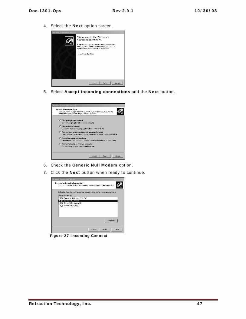
4. Select the Next option screen.
5. Select Accept incoming connections and the Next button.
6. Check the Generic Null Modem option.
7. Click the Next button when ready to continue.
Figure 27 Incoming Connect

130-01 Operations
Refraction Technology, Inc. 48
8. Select the Allow option on the Incoming Virtual Connection window.
9. Click the Next button.
Figure 28 Allow Incoming Virtual
10. Select the Add button to add a new DAS connection.
Figure 29 Add DAS User
Note: When a DAS unit is setup and is connected to a PC, an account must be created and added. The account Username MUST be the particular DAS unit ID that is directly connected to the PC.
Doc-1301-Ops Rev 2.9.1 10/30/08
Refraction Technology, Inc. 49
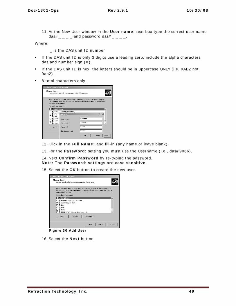
11. At the New User window in the User name: text box type the correct user name das#_ _ _ _ and password das#_ _ _ _,
Where:
_ is the DAS unit ID number
If the DAS unit ID is only 3 digits use a leading zero, include the alpha characters das and number sign (#).
If the DAS unit ID is hex, the letters should be in uppercase ONLY (i.e. 9AB2 not 9ab2).
8 total characters only.
12. Click in the Full Name: and fill-in (any name or leave blank).
13. For the Password: setting you must use the Username (i.e., das#9066).
14. Next Confirm Password by re-typing the password. Note: The Password: settings are case sensitive.
15. Select the OK button to create the new user.
Figure 30 Add User
16. Select the Next button.

130-01 Operations
Refraction Technology, Inc. 50
17. In the Network Components window, under the components, highlight Internet Protocol (TCP/IP).
18. Select the Properties button.
Figure 31 Networking
19. On the Incoming TCP/IP Properties, enable Allow callers to access my local area network.
Figure 32 Remote Access
20. Enable Specify TCP/IP address.
21. In the From: text box type a generic IP address where:
From IP address = PC’s PPP IP address.
22. In the To: text box type a destination IP address where:
To IP address = Range of IP address for Serial PPP pool.
23. Click OK when ready.
24. Click Finish after naming the connection.

Doc-1301-Ops Rev 2.9.1 10/30/08
Refraction Technology, Inc. 51
3.2.3 Start Remote Access Service (RAS) Windows provides a services control program. It must be used to start RAS. The control program can be accessed through the Windows Control Panel:
For Windows 2000:
Start -> Settings -> Control Panel -> Administrative Tools -> Services
For Windows XP:
Start -> Settings -> Control Panel -> Administrative Tools -> Services -> Component Services.
A shortcut to the control program has also been placed at Start -> Programs -> Refraction Technology -> RTP Services -> Services. The shortcut can be copied to the windows desktop by dragging it to the desktop while holding down the CTRL key.
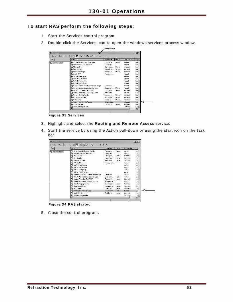
130-01 Operations
Refraction Technology, Inc. 52
To start RAS perform the following steps:
1. Start the Services control program.
2. Double-click the Services icon to open the windows services process window.
Figure 33 Services
3. Highlight and select the Routing and Remote Access service.
4. Start the service by using the Action pull-down or using the start icon on the task bar.
Figure 34 RAS started
5. Close the control program.
Start icon

Doc-1301-Ops Rev 2.9.1 10/30/08
Refraction Technology, Inc. 53
3.3 Modem PPP Connection
3.3.1 130-Modem The REF TEK 130-Modem which is shown below, is capable of providing the same functions as the internal SLM2456 modem module and can be used in all of the REF TEK 130 Series Data Acquisition System family. The unit looks similar to the 130-GPS except it has the 130-Modem label on the end of the unit and two wires connected as shown below.
Figure 35 130 Modem
3.3.2 DAS Setup This Section explains the REF TEK 130-Modem when it is used with the REF TEK 130 family. The 130-Modem is an optional external modem.
A user should be familiar with whatever REF TEK host system is in current use. Documents for other REF TEK products are available on request.
Note Labelon 130-Modem

130-01 Operations
Refraction Technology, Inc. 54
3.3.3 Setting up the 130 to use the 130-Modem 1. Connect the 130-Modem to the 130 DAS unit NET connector, using the standard
REF TEK 130-8154 cable supplied with the 130-Modem unit, this cable is also available separately (see drawing).
2. Attach the phone line connector to an available phone line connection.
The REF TEK 130-8154 130-Modem-to-DAS cable referred to above is wired as follows:
Modem Connector PT06A1210P(SR)
130 Net Connector (PT06A14-19S)
Signal Phone Line
Cable PIN A PIN A RX PIN B PIN B TX PIN C PIN C RTS PIN D PIN D CTS PIN E PIN E GND PIN F PIN F CCD PIN G - Phone - TIP Red - 2 PIN H - Phone - RING Green - 3 PIN J PIN G 5V PIN K PIN M 12 V
No additional cables are needed to operate the 130-Modem and REF TEK 130. The user should consult applicable literature for other host devices.

Doc-1301-Ops Rev 2.9.1 10/30/08
Refraction Technology, Inc. 55
3.4 SLM Modem module The SLM2456 modem module is used in the 130-Modem and as the internal modem for the 130-01. The SLM2456 is a complete, modem module that is based on the Si2456 chipset. The Si2456 is an ITU-V.90 compliant, 56 kbps modem chipset with integrated direct access arrangement (also called DAA it includes parallel phone detect, over-current detection and global PTT compliance). This provides a programmable line interface to meet global telephone line requirements. It is a single design that includes a DSP data pump, a modem controller, on-chip RAM and ROM, an analog front end (AFE) a DAA, and analog output.
Note: The 130-8137 modem cable is used with the 130-01 when supplied with an internal modem.
3.4.1 Modem features The SLM2456 accepts standard modem AT commands and provides connect rates up to 56/33.6/14.4 kbps full-duplex over the Public Switched Telephone Network (PTN). It also features a complete set of modem protocols including all ITU-T standard formats up to 56 kbps.
Note: This material is part of the Silicon Laboratories® Si2456/33/14 data sheet document revision 1.0. See the Si2456/33/14 Users Guide (“AN70:Si245/Si2433/Si2414/Si2403 Modem Designer’s Guide) for detailed feature explanations.

130-01 Operations
Refraction Technology, Inc. 56
3.5 Modem configuration Note: The internal modem (used on the 130-SM) requires the jumper installed on the RT530 lid board to assign the serial PPP port to the internal modem and therefore disable the serial PPP port coming out of the NEt connector.
3.5.1 PFC_130 Serial PPP Use the Serial PPP settings within the PFC_130 to configure the modem.
Note: Serial PPP settings are for internal and external modem control. If a modem is connected the user MUST use these settings to configure the modem.
1. Use the Control menu Net button to assign Serial PPP parameters for the modem.
Figure 36 PFC Control
2. Click the Line Mode (type of serial connection) pull-down arrow and select the AT/Modem option from the pull-down.
Note: Direct - Connection to a PC or router or FW in point-to-point mode. FW Multi - Connection to a Freewave operating in multipoint mode. AT/Modem - Connection to a modem.
3. Click the Baud Rate (serial port speed) pull-down arrow and select the 19200 baud rate.
Figure 37 Assign Baud
Note: It is preferred to set the port speed at 19200 to allow for phone noise and the modem buffering to keep up.
3 3

Doc-1301-Ops Rev 2.9.1 10/30/08
Refraction Technology, Inc. 57
4. After assigning Serial PPP parameters use the Send button to send them to the DAS.
Note: When the Send button is selected both Ethernet and Serial PPP IP configuration are sent to the DAS at the same time. So it is therefore possible to edit both sets of configurations at the same time and only send them to the DAS once.
If using AT/Modem - Line Mode:
1. Select the Modem button to adjust the modem settings.
Figure 39 Modem Setup
2. Tap after the Init field and provide the modem initialization parameters as shown below (ATE0S0=1).
Note: Type the init string exactly as shown above. The init string is the ONLY string that works. It is sent to the modem on both boot up of the 130-01 and/or if sent from the above window using the Send button.
1
ftp ONLYData via
Figure 38 Send Serial PPP

130-01 Operations
Refraction Technology, Inc. 58
3. Tap the Send button to send the modem parameters to the DAS.
4. Tap the Done button to return to the Connection setup menu.
Figure 40 Send
3.5.2 Data transfer through PPP real-time If you want data to be transferred real-time through PPP then it must be marked in the data stream parameters and the RTPD host IP entered in the PPP menu.
If the remote cannot find RTPD when carrier detect goes high, at the IP address entered for RTPD, it will hang up the line.
The remote does not call out automatically when using a modem. It will drop the line if it does not negotiate with an RTPD host address other than 0.0.0.0.
If the data is streamed over PPP and the link is getting saturated, at some point the 130 will close the RTPD connection, reset the DAS and take the link down.
FTP cannot be used if the PPP link is talking or connecting to an RTPD. Note: If the user wants to use the real-time and ftp option, they must stop acq first and allow the serial data buffer to clear before doing ftp or the unit will lock up and will be reset by the watchdog after 60 seconds.
Send

Doc-1301-Ops Rev 2.9.1 10/30/08
Refraction Technology, Inc. 59
3.6 PC Communication Setup
3.6.1 130 DAS modem communication Note: The modem at the 130-01 DAS end of the line should be pre-configured to automatically answer before trying to dial to the DAS.
The following steps are an example of the steps necessary to configure the 130-01 DAS modem to automatically answer.
1. Be sure the modem is connected an open COM port on the PC.
2. Open a Hyper Terminal window using: Start --> Program --> Accessories --> Communications --> Hyper Terminal
3. Create a new 130-01 DAS connection session.
4. Enter the Connect using option as COM for the connection.
5. Set the Port Settings to the port settings of the 130 modem.
i.e. Bits per second to the baud rate of the 130 modem.
6. Once connected enter AT commands necessary for the specific modem installed to automatically allow auto-answer.
i.e. AT S0=1

130-01 Operations
Refraction Technology, Inc. 60
3.6.2 Install modem Note: This section only applies if a modem has not already been installed on the PC.
This section describes requirements for dialup into a 130-01 Recorder on a computer running Windows 2000.
1. Connect the modem to an open COM port of the PC.
2. Open the Start --> Settings --> Control Panel --> window to add a modem.
3. Double-click the Phone and Modem Icon.
Figure 41 Add Modem
4. Select the Modem option tab to continue the setup.
Figure 42 Phone and Modem Options
Add modem
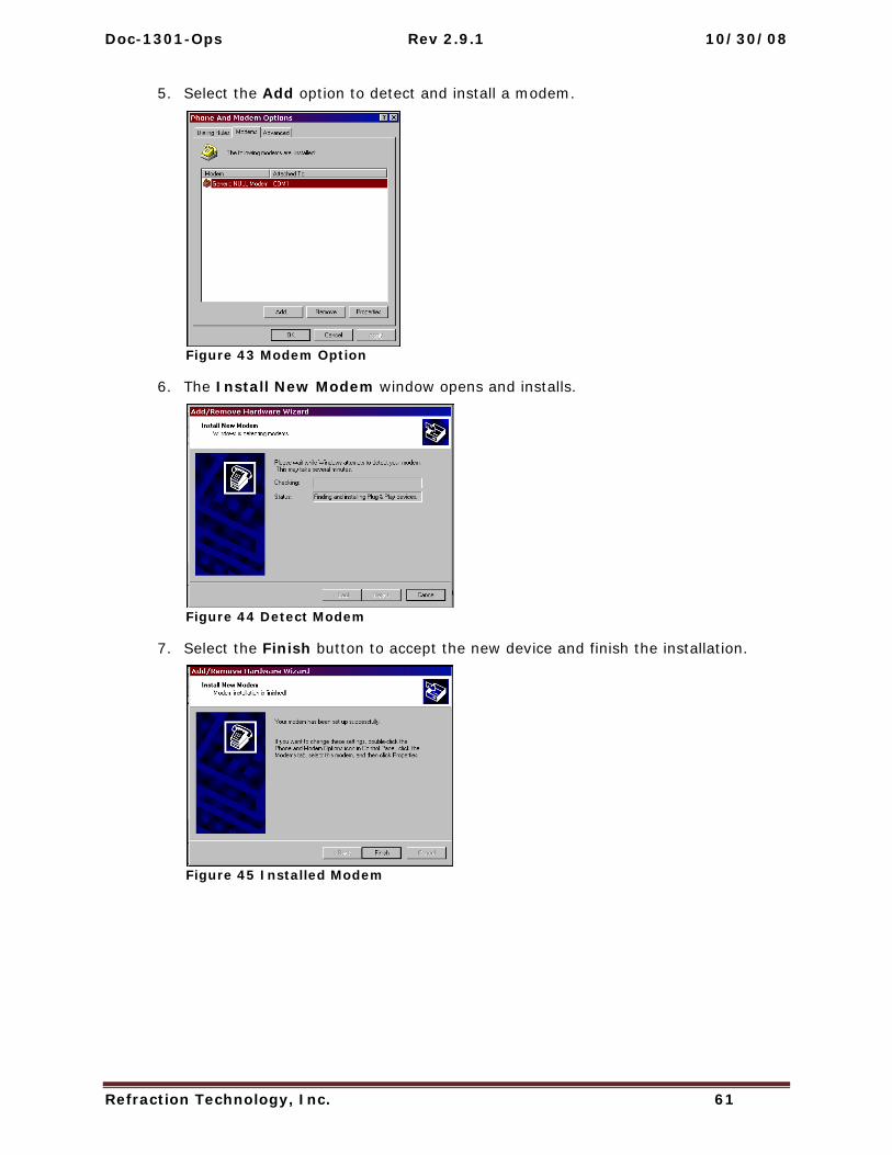
Doc-1301-Ops Rev 2.9.1 10/30/08
Refraction Technology, Inc. 61
5. Select the Add option to detect and install a modem.
Figure 43 Modem Option
6. The Install New Modem window opens and installs.
Figure 44 Detect Modem
7. Select the Finish button to accept the new device and finish the installation.
Figure 45 Installed Modem

130-01 Operations
Refraction Technology, Inc. 62
8. The Phone and Modem Options window displays to show the new modem.
Figure 46 New Modem
9. Highlight the new modem.
10. Select the Properties button to set the baud rate for the modem.
11. Set the Baud rate from the drop-down menu and Select the OK button.
Figure 47 Modem Properties

Refraction Technology
Refraction Technology, Inc. 63
4 Periodic Maintenance Operations
4.1 Introduction This section provides maintenance information for the 130-01/3 and 130-01/6 on the following topics:
Replacing the Compact Flash
Connector Assembly & Maintenance
Periodic Maintenance checks
Replace CPU Battery (130-01/3 and 130-01/6)
Disassembly of the 130 for service
Sealing and pressure testing a 130-01 DAS
Adding or replacing an RT527
Testing the 130 DAS Memory
This section provides maintenance procedures that increase the effectiveness and useful life of your recorder unit(s).
WARNING: All REF TEK circuit boards are Static Sensitive and appropriate handling is required to protect each board from damage due to Static discharge.
1. Please insure that when handling REF TEK circuit boards, the handler and the work bench are grounded. This is usually done via a grounding mat on the bench, which is ultimately grounded to the building ground and also attached to the handler.
2. When shipping individual boards they must be wrapped in anti-static protection, either anti-static bags or boxes. REK TEK can supply these if requested.
3. Failure to protect against static increases the chance of boards being damaged and may void REF TEK warrantee.

130-01 Operations
Refraction Technology, Inc. 64
4.2 Replacing the Compact Flash If the Compact Flash needs to be changed do the following
1. Remove the cap off the 130-01 DAS.
2. If the LED, in the disk well assembly next to where the Compact Flash is
installed, shows “Green”, it can be replaced with an empty formatted drive. Note: If the LED shows Red the drive is reading data; DO NOT REMOVE THE DRIVE UNTIL THE LED CHANGES TO GREEN.
The following conditions could result if a drive is replaced while the LED is Red:
Loss of data on the drive.
The drive may have to be reformatted.
The 130 DAS may have to be power-cycled. Note: DO NOT TOUCH THE DRIVE, except when replacing the tape.
3. Use only the provided tab, attached to the Compact Flash.
Use the provided tab to remove the Compact Flash
Disk 1Disk 2

Doc-1301-Ops Rev 2.9.1 10/30/08
Refraction Technology, Inc. 65
Note: DO NOT HOLD the drive in the middle as it may damage the drive.
4. Handle the drive by grasping the sides of the drive with the other hand.
Figure 48 Handle drive
5. Install a newly formatted drive in either slot by holding (ONLY) onto the sides of the Compact Flash and inserting into the well or reader.
Figure 49 Install Drive
6. The LED, for the well slot, should turn “Green”.

130-01 Operations
Refraction Technology, Inc. 66
When using the Compact Flash with a Compact Flash Reader:
7. Grasp only the edges while inserting the drive into the Compact Flash Reader.
Figure 50 Compact Flash
8. Grasp only by edges or tab to install or remove the drive.
CF Disk Warning: Due to the large variability of CF cards available on the world market and the resulting problems with compatibility due to memory layout, signal structuring and power requirements, Refraction Technology cannot guarantee a CF card will work in a REF TEK data recorder unless it is sold through REF TEK itself. REF TEK ensures compatibility through communications with CF manufacturers and rigorous in-house testing. Some CF manufacturers refuse to provide adequate information or factory controls to ensure that the product being sold today is the same as the product sold earlier under the same part number. CF cards not purchased from REF TEK may work at one temperature but not at another, or may fail all together.

Doc-1301-Ops Rev 2.9.1 10/30/08
Refraction Technology, Inc. 67
4.3 Connector Assembly & Maintenance To allow you to choose the particular peripherals to use (such as power supply, modem, and external clock), and suitably locate them, REF TEK typically does not always supply complete cables with your recorder. Instead, REF TEK supplies a kit that contains the mating connectors that you need to construct the cables required by your particular peripherals and system configuration. Upon order, REF TEK will supply any or all of our standard connector cables (as described later). Also, REF TEK will construct any custom cables your system needs. For some of the more standard connector/cable drawings of commonly used assemblies see “Standard Faceplate Connections”.
Pin connections are supplied in your recorder manual (Starting in Chapter 1, “Overview”). When making the connections follow industry standard practices in dressing the cable end, soldering the connections and applying shrink tubing. The use of self-vulcanizing tape is preferred to potting the connector since with potting, the connector is no longer field serviceable.
Note: For additional moisture protection, apply DL-111 inside the top shell to seal against the rubber grommet. Bottom shell must rotate freely after the top shell has been firmly tightened into the connector body.
The recommended periodic connector maintenance and usage is as follows:
1. Plugs labeled “PT06” have a superintending outer locking collar with a machined inner groove that locks onto the pegs in the side of the panel mount mate receptacle. When removing a PT06 connector, move it out of the locked position by first applying a downward force on the outer collar and then twisting it free in a counter-clockwise direction.
2. Be careful with tools when gripping connectors - use tools with nylon fittings in the jaws if you can, and do not apply excessive force.
3. The connectors have a machined groove inside. To avoid damaging this groove, you must apply a downward force while turning. Because connectors for the 130 DAS units are constructed of an alloy, excessive force on the locking groove can cause burrs which make subsequent installation and removal of the connectors more difficult.
4. Do not attempt to remove a plug with pliers.
5. Assemble new connectors correctly as shown below.

130-01 Operations
Refraction Technology, Inc. 68
Figure 51 PTO Connector
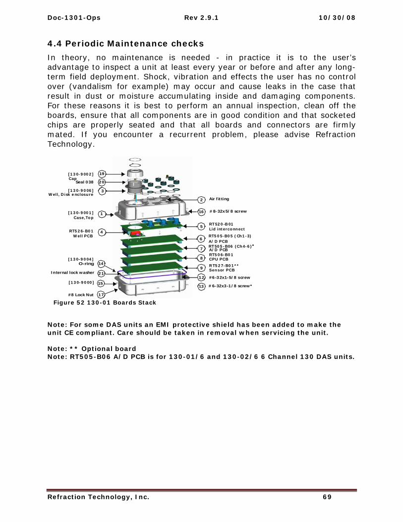
Doc-1301-Ops Rev 2.9.1 10/30/08
Refraction Technology, Inc. 69
4.4 Periodic Maintenance checks In theory, no maintenance is needed - in practice it is to the user’s advantage to inspect a unit at least every year or before and after any long-term field deployment. Shock, vibration and effects the user has no control over (vandalism for example) may occur and cause leaks in the case that result in dust or moisture accumulating inside and damaging components. For these reasons it is best to perform an annual inspection, clean off the boards, ensure that all components are in good condition and that socketed chips are properly seated and that all boards and connectors are firmly mated. If you encounter a recurrent problem, please advise Refraction Technology.
Figure 52 130-01 Boards Stack
Note: For some DAS units an EMI protective shield has been added to make the unit CE compliant. Care should be taken in removal when servicing the unit. Note: ** Optional board Note: RT505-B06 A/D PCB is for 130-01/6 and 130-02/6 6 Channel 130 DAS units.
RT526-B01
Well, Disk enclosure
Case,Top[130-9001]
Cap[130-9002]
O-ring
Well PCB
[130-9000]
[130-9004]
RT505-B05 (Ch1-3)
RT520-B01
RT505-B06 (Ch4-6)*
RT506-B01
Lid interconnect
A/D PCB
A/D PCB
CPU PCB
Sensor PCBRT527-B01**
[130-9006]
1
2
3
Air fitting
45
6
7
8
9
12 #6-32x1-5/8 screw
13 #6-32x3-1/8 screw*
14
15
16 #8-32x5/8 screw
17#8 Lock Nut
19
20Seal 038
21Internal lock washer

130-01 Operations
Refraction Technology, Inc. 70
4.5 Replace CPU Battery (130-01/3 and 130-01/6) The CPU board has a 3.6 volt back-up battery, located in the well area, to retain CPU RAM when the recorder is powered off or asleep. If the LCD display shows less than 2.2 volts for the battery it should be replaced.
Refer to Figure 52 on page 69
1. The power to the 130-01 may be left on so data in memory will not be lost.
2. Remove the cap (130-9002) (Item 19) from the well disk enclosure (Item 3).
3. Disconnect the connector for the battery from the pins located next to the fin clip inside the well.
4. Gently remove the battery assembly (130-9007) (Item 18) from the fin clip inside.
5. Insert the new battery assembly (130-9007) (Item 18) into the fin clip inside the well disk enclosure (Item 3).
6. Attach the connector off the new battery assembly (130-9007) (Item 18) to the pins located next to the fin clip inside the well disk enclosure (Item 3).
7. Check the LCD display to be sure the voltage is now close to 3.6 volts.
8. Screw the cap (130-9002) (Item 19) onto the well enclosure (Item 4).
9. Once the cap bottoms out to the flange turn the cap ONLY A HALF TURN to seal the well.
Battery voltage

Doc-1301-Ops Rev 2.9.1 10/30/08
Refraction Technology, Inc. 71
4.6 Disassembly of the 130 for service To disassemble a 130-01 refer to Figure 52 on page 69 and follow these steps:
1. Power off the 130-01.
2. Check and make sure the cap (130-9002) is installed on the well disk enclosure (Item 3).
3. Flip the 130-01 DAS upside-down on the top of the top case (Item 1).
4. Unbolt the bottom base case (Item 15) of the recorder by removal of twelve #8-32x5/8 screws (Items 16) and the twelve #8 lock nuts (Item 17).
Note: The order of removal is not important until the 130 DAS needs to be assembled.
5. Remove the bottom half of the case (130-9000) (Item 15). Note: Make sure the O-ring (Item 14) (130-9004) stays on the bottom half of the 130-01 DAS assembly.
6. If the DAS has a protective EMI shield, remove the cover (form-fitting plastic).
7. If boards need to be removed, loosen and remove the six #6-32 screws (Item 12) or (Item 13) from the stack.
Note: Retain the lock washers (Item 21) with the screws so they do not get misplaced.
8. Disconnect the CPU ribbon cables (Item 10) and (Item 11) from the CPU board (Item 9) by spreading the ears on the connections of the CPU board (Item 9).
9. At this point the individual boards may be gently lifted off the stack.
10. The 130-01 DAS configuration can be changed, at this time, by:
Adding a memory expansion board to the top of the CPU board (Item 9). Make sure the board notches match where the cable connectors for the ribbon cables (Item 10) and (Item 11) are located on the board.
Adding a sensor control board (Item 8) after removing the CPU board (Item 9).
Upgrade the 130-1/3 to a 130-1/6 6-Channel recorder.
11. Refer to “Assembly of the 130” on page 76 to assemble the 130 DAS.

130-01 Operations
Refraction Technology, Inc. 72
4.6.1 130-01 Bill of Materials
Figure 53 130-01/3 Bill Of Materials

Doc-1301-Ops Rev 2.9.1 10/30/08
Refraction Technology, Inc. 73

130-01 Operations
Refraction Technology, Inc. 74

Doc-1301-Ops Rev 2.9.1 10/30/08
Refraction Technology, Inc. 75

130-01 Operations
Refraction Technology, Inc. 76
4.7 Assembly of the 130 Assemble the 130 DAS (Figure 52 on page 69) as follows:
1. Gently re-stack the boards in the order shown in Figure 52. Note: If new boards are added remember the CPU board is always last unless a memory expansion board is added, in this case the memory board is mounted last.
2. If the DAS has an EMI protective shield, either close the flaps re-install the cover (plastic).
3. Insert the six removed #6-32 screws (Item 12) or (Item 13) with the lock washers (Item 21).
4. Tighten the stack of boards with a screwdriver.
5. Connect the loose end of the ribbon cables (Item 10) and (Item 11) by locating the first pin on the connector and applying pressure until the ears of the connector close.
6. Place the O-ring in the bottom half of the case (Item 15).
7. Place the completed flipped case assembly (Item 1) onto the case bottom base (Item 15) making sure the O-ring sits in the groove of the top case as well.
8. Bolt the two halves of the 130-01 DAS together using twelve #8-21x5/8 SS screws (Item 16) and #8 lock nuts (Item 17).
9. Seal and pressure test the 130-01 DAS. Refer to Step 7 on “Sealing and pressure testing a 130-01 DAS”.
Note: Follow the pattern shown below in below to install and hand tighten the nuts to the screws. Then tighten all twelve screws in the same pattern.
Figure 54 Tighten Pattern
1
2
3
4
5
67
810
9
11
12

Doc-1301-Ops Rev 2.9.1 10/30/08
Refraction Technology, Inc. 77
4.8 Sealing and pressure testing a 130-01 DAS Recorder units in the plastic cases must be reassembled correctly so that they remain properly sealed and moisture proof. The top and bottom case incorporates an O-ring that forms the seal. The O-ring is very lightly lubricated with a hydrocarbon based silicone and it must be correctly seated before the recorder is reassembled. REF TEK provides a spares kit that includes an O-ring and other assembly hardware for each recorder. Extra O-rings can be ordered under part number 130-8003 as part of the spares kit.
Each recorder also contains two desiccant packets that should be replaced when the recorder is opened. Desiccant packs can be reactivated by following the instructions on the packs. Alternately, a pair of desiccant packs can be put in a microwave at half power for three to five minutes to re-activate them.
Following reassembly (See “Assembly of the 130”) it is advisable to pressure test a recorder before use, as described below. After a successful test the recorder should be returned to atmospheric pressure. The test should show no significant pressure drop (at constant temperature) over a 24-hour period.
To reassemble and pressure test, a 130 DAS, refer to Figure 52 and proceed as follows:
1. Clean the O-ring groove in the bottom base case (Item 25).
2. Clean the O-ring groove in the case top case (Item 1).
3. Flip over the top case assembly with the board stack. Note: Make sure the cap is on the disk well.
4. Carefully slide the O-ring into position into the groove of the flipped top case assembly (Item 1).
Note: Try to avoid stretching the O-ring unduly.
5. If the DAS has a protective EMI shield, either close the flaps install the cover (plastic).
6. Carefully lower the recorder bottom base case (Item 25) onto the top case assembly half of the 130-01. Observe the O-ring and check that the corners do not get caught and displaced or gouged as the unit is seated on the top.
7. Install the retaining screws, using twelve #8-21x5/8 SS screws (Item 16) and #8 lock nuts (Item 17), and tighten them in the order shown (Figure 76) to seal the unit.
8. Pressurize the unit to about 1 psi with air and note the precise reading. This value should remain constant for at least 24 hours. Alternately, a 5-minute water immersion test may be used if the person doing the test keeps a close watch (for bubbles).

130-01 Operations
Refraction Technology, Inc. 78
4.9 Firmware update options WARNING: If the firmware flash is interrupted the 130 may not boot again and the 130 must be returned to the factory for service or optional EEPROM board must be used. If you live in an area of unreliable power a UPS is recommended. NOTE: DAS power must be above 11.5V to upgrade firmware.
4.9.1 Download firmware from the FTP site 1. Login to our FTP site at: ftp.reftek.com/pub as:
User name: Anonymous
Password: Your E-mail address
2. Find the 130-01 firmware at ftp.reftek.com/pub/130/cpu/prom.
3. Download the zip file of the most recently released firmware version.
4.9.2 Firmware update process Updating firmware in a 130-01 requires the presence of a firmware file on an installed Compact Flash device.
1. On power-up, the 130-01 checks the Compact Flash for the presence of ‘main.s3’ in the root directory.
2. If the ‘main.s3’ file is present on the Compact Flash, the 130-01:
(a) Reads the file.
(b) Re-programs the internal flash memory.
(c) DELETES the file. Note: DO NOT DISTURB THE UNIT DURING THIS PROCESS.
4.9.3 Updating firmware from a Compact Flash™ 1. Unzip the ‘main.s3’ file from the downloaded zip file of the most recently released
firmware.
2. Copy the desired firmware image to the root of the Compact Flash as ‘main.s3’ using a PC with a Compact Flash™ reader.
3. Install the Compact Flash™ in the 130-01.
Updating firmware in a 130-01 requires the presence of a firmware file on an installed Compact Flash device.
4. On power-up, the 130-01 checks the Compact Flash™ for the presence of ‘main.s3’ in the root directory.
5. If the ‘main.s3’ file is present on the Compact Flash™, the 130-01:
(a) Reads the file.
(b) Re-programs the internal flash memory.
(c) DELETES the file. Note: DO NOT DISTURB THE UNIT DURING THIS PROCESS.

Doc-1301-Ops Rev 2.9.1 10/30/08
Refraction Technology, Inc. 79
4.9.4 Updating firmware using ftp 1. ftp to the 130-01 using its IP address:
username: reftek
password: reftek
2. Use the ls ftp command to list the contents of the Compact Flash™.
3. Enter bi and ha to select Binary and Hash options.
4. Use the put ftp command to send the file (main.s3) to the Compact Flash™ installed on the 130-01.
5. With the Compact Flash™ with the main.s3 image installed in the 130-01 DAS, issue a reset command from the 130-01
-OR-
Use the RTCC command and control interface program
Use the RT130-SM GUI Reset System command
6. On power-up, the 130-01 checks the Compact Flash™ for the presence of ‘main.s3’ in the root directory.
7. If the ‘main.s3’ file is present on the Compact Flash™, the 130-01:
(a) Reads the file.
(b) Re-programs the internal flash memory.
(c) DELETES the file.
DO NOT DISTURB THE UNIT DURING THIS PROCESS.
4.9.5 Updating firmware at the 130-01 1. Issue a Reset command from a PDA running PFC_130 or Physically disconnect
and reconnect power to the unit.
2. Observe the LCD for the following messages:
READING DISK DO NOT DISTURB
WRITING FLASH DO NOT DISTURB
3. The 130-01 DAS resets and returns to normal messaging.

130-01 Operations
Refraction Technology, Inc. 80
4.9.6 Updating firmware via telemetry mode 1. If you are connecting remotely by a TCP connection:
First connect
Discover the unit
Acquire status
2. Issue a reset command from the Status screen.
3. Delete the unit from the Station List screen:
Wait at least 5 minutes
At the Connections screen (reconnect id using a TCP connection) issue a Station Discovery again to discover the 130 DAS station.
Note: DO NOT DISTURB THE UNIT until the start-up LCD message reappears.

Doc-1301-Ops Rev 2.9.1 10/30/08
Refraction Technology, Inc. 81
4.10 To Test the 130 DAS Memory
4.10.1 Overview This Section explains the how the Memory Test (MT) command is handled in the REF TEK 130-01 DAS.
4.10.2 Memory test process The Memory Test Command causes the REF TEK 130-01 to perform a memory test on data and buffer memory. Since the test overwrites any existing data, the DAS performs several actions prior to starting the actual test. Acquisition is stopped (if currently active), the DAS attempts to dump all recorded data and processes not required to perform the memory test are stopped.
Memory is checked using 0xAA, 0x55 and incremental data patterns.
If an error is detected, the test is stopped immediately and the DAS responds with the FAIL result code and failing address.
Upon successful completion of the test, the DAS responses with the PASS result code and 0x00000000 as the failing address.
Note: The test status and the PASS/FAIL results are also available on the LCD display.
After a 20 second delay the system automatically reboots.
All configuration parameters are restored to the conditions prior to the MT command being issued. This includes starting acquisition, if it was running prior to receipt of the command.


Refraction Technology
Refraction Technology, Inc. 83
5 Adding or replacing an RT527
5.1 Overview This document provides installation information to add or replace the Sensor Control board (RT527) in the 130 DAS family systems. Refer to the RT527 board technical reference information for the RT527.
Note: Please read all instructions carefully before proceeding. If you have any questions please call or E-mail REF TEK.
Figure 55 RT527 SCB

130-01 Operations
Refraction Technology, Inc. 84
5.2 Installation To install the RT527 in the 130-01 DAS follow these steps:
1. Upgrade the 130-01 to a minimum firmware version of 2.1.0 or later (see the “Update Firmware” section (Page 78) in the System Operations Manual).
2. Power off the 130-01.
3. Check and make sure the cap (130-9002) is installed on the well disk enclosure (Item 3) as shown on page 87.
4. Flip the 130-01 DAS upside-down on the top of the top case (Item 1).
5. Unbolt the bottom base case (Item 15) of the recorder by removal of twelve #8-32x5/8 screws (Items 16) and the twelve #8 lock nuts (Item 17).
Figure 56 Unbolt 130 Case
Note: The order of screw removal is not important.

Doc-1301-Ops Rev 2.9.1 10/30/08
Refraction Technology, Inc. 85
6. Remove the bottom half of the case (130-9000) (Item 15).
7. Make sure the O-ring (Item 14) (130-9004) stays on the bottom half of the 130-01 DAS assembly.
Figure 57 Remove 130 Top
8. Loosen and remove the six #6-32 screws (Item 12) or (Item 13) from the stack.
Figure 58 Stack Screws
9. Retain the lock washers (Item 21 on Figure 52) with the screws so they do not get misplaced.

130-01 Operations
Refraction Technology, Inc. 86
For a new installation of the RT527 go to Step 12. If an upgrade of an RT527 go to Step 10.
5.2.1 Upgrade 10. If an upgrade or replacement of the RT527 (Item 9 on Figure 59 on page 87) is
desired, gently lift and remove the old sensor control board (RT527) (Item 9).
11. Install the six original #6-32 screws to secure the board stack and go to Step 14.
5.2.2 For a new installation: 12. If adding (installation) of an RT527 (Item 9) is desired, gently attach the new
board to connector making sure the board connectors line up and fit correctly.
13. For a new (installation) install the 6 (longer) #6-32 screws supplied with the RT527 board.
14. Place the O-ring in the bottom half of the case (Item 15).
Figure 59 Install O-Ring
15. Place the completed flipped case assembly (Item 1) onto the case bottom base (Item 15) making sure the O-ring sits in the groove of the top case as well.

Doc-1301-Ops Rev 2.9.1 10/30/08
Refraction Technology, Inc. 87
16. Bolt the two halves of the 130 DAS together using twelve #8-21x5/8 SS screws (Item 16) and #8 lock nuts (Item 17).
Note: Follow the pattern shown in Figure 60 to install and hand tighten the nuts to the screws. Then tighten all twelve screws in the same pattern.
Figure 60 130-Exploded View
Figure 61 Bolt Pattern
RT526-B01
Well, Disk enclosure
Case,Top[130-9001]
Cap[130-9002]
O-ring
Well PCB
[130-9000]
[130-9004]
RT505-B05 (Ch1-3)
RT520-B01
RT505-B06 (Ch4-6)*
RT506-B01
Lid interconnect
A/D PCB
A/D PCB
CPU PCB
Sensor PCBRT527-B01**
[130-9006]
1
2
3
Air fitting
45
6
7
8
9
12 #6-32x1-5/8 screw
13 #6-32x3-1/8 screw*
14
15
16 #8-32x5/8 screw
17#8 Lock Nut
19
20Seal 038
21Internal lock washer
1 2
3
4
5
97
8
6
10 12
11
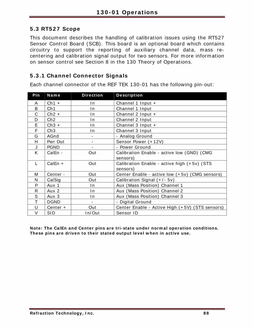
130-01 Operations
Refraction Technology, Inc. 88
5.3 RT527 Scope This document describes the handling of calibration issues using the RT527 Sensor Control Board (SCB). This board is an optional board which contains circuitry to support the reporting of auxiliary channel data, mass re-centering and calibration signal output for two sensors. For more information on sensor control see Section 8 in the 130 Theory of Operations.
5.3.1 Channel Connector Signals Each channel connector of the REF TEK 130-01 has the following pin-out:
Pin Name Direction Description
A Ch1 + In Channel 1 Input + B Ch1 In Channel 1 Input C Ch2 + In Channel 2 Input + D Ch2 In Channel 2 Input E Ch3 + In Channel 3 Input + F Ch3 In Channel 3 Input G AGnd - - Analog Ground H Pwr Out - Sensor Power (+12V) J PGND - - Power Ground K CalEn - Out Calibration Enable - active low (GND) (CMG
sensors) L CalEn + Out Calibration Enable - active high (+5v) (STS
sensors) M Center - Out Center Enable - active low (+5v) (CMG sensors) N CalSig Out Calibration Signal (+/- 5v) P Aux 1 In Aux (Mass Position) Channel 1 R Aux 2 In Aux (Mass Position) Channel 2 S Aux 3 In Aux (Mass Position) Channel 3 T DGND - - Digital Ground U Center + Out Center Enable - Active High (+5V) (STS sensors) V SID In/Out Sensor ID
Note: The CalEn and Center pins are tri-state under normal operation conditions. These pins are driven to their stated output level when in active use.

Doc-1301-Ops Rev 2.9.1 10/30/08
Refraction Technology, Inc. 89
5.3.2 Sensor Test Signals Sensors vary in the number and type of signals they support. The following table shows some common sensors used with the Ref Tek 130-01:
Sensor Mass Center CalSig CalEn Notes
Outputs Inputs Inputs Inputs
131A - - - 1 ( +5v ) Self-test output while enabled LE3Dlite - - - 1 (GND) Fixed self-test starts on falling
edge L4C - - 1 - S13 - - 1 - CMG-3ESP 3 1 (GND) 1 3 (GND) Center enable > 0.2 S CMG-3T 3 1 (GND) 1 3 (GND) Center enable > 0.2 S CMG-40T 3 - 1 3 (GND) STS 3 1 ( +5v ) 3 1 ( +5v ) Center enable > 0.5 S
5.3.3 Auxiliary Channels Three auxiliary channels are provided on each sensor connector. Each channel connects to a 12-bit A/D converter with an input range of +/- 10v. These channels are read once per second and stored as left-justified, 2’s-compliment, 16-bit values. This equates to a bit-weight of 305.2 uV. These channels can be used to measure mass position or other auxiliary input data, such as temperature and wind speed. The current readings of the auxiliary channels are available on demand using the Auxiliary Data status response (SS:AD).
Mass re-center
Mass re-centering can be performed on-demand. The Sensor Calibration – Mass re-center (SK:M) command forces activation of the Center pins of a specified sensor for 1-2 seconds. Automatic re-centering is enabled using the PQ parameters. This assumes that the auxiliary input channels are connected to the mass position outputs of a sensor.

130-01 Operations
Refraction Technology, Inc. 90
Pseudo-code (some error and border conditions not covered):
count limit = ((Time * 3600) / Rate) if (Attempts == 0) Attempts = 1 retry = Attempts ...… if (Rate seconds has passed) { if (reading < Level) { if (counter > 0) counter = counter - 1 } else /* reading >= Level */ { counter = counter + 1 if (counter >= count limit) { activate center signal retry = retry - 1 if ((retry != 0) AND (Interval != 0)) counter = counter – ((Interval * 60) / Rate) else counter = 0 } } if (counter == 0) retry = Attempts

Refraction Technology
Refraction Technology, Inc. 91
6 Logfile Example
6.1 Timing examples
289:22:14:42 EXTERNAL CLOCK WAKEUP
The DAS issues a command to turn on the power to the 130 GPS.
323:06:03:10 EXTERNAL CLOCK POWER IS TURNED ON
The DAS gets a confirmation message from the 130-GPS that it has powered up.
289:22:15:58 EXTERNAL CLOCK IS UNLOCKED
The DAS receives messages from the 130-GPS that it is not locked. The 130 GPS is powered up and searching for satellites to lock onto but does not have enough satellites to declare a lock.
289:22:16:58 EXTERNAL CLOCK IS LOCKED The DAS receives a locked message from the 130-GPS. The DAS will then use the 130-GPS to correct its internal oscillator.
018:09:06:44 INTERNAL CLOCK TIME JERK ENABLED The DAS compares the 130-GPS time to its internal oscillator time at the first GPS lock since the 130 power-up or reset. If a change is required to equal the 130-GPS time, it enables the timing algorithm that makes the change, Time Jerk. It gives the time it was enabled and will jerk the DAS internal clock with the next 1PPS or 1 Hz rise from the 130-GPS.
018:09:06:44 INTERNAL CLOCK TIME JERK # 1 OCCURRED AT 09:06:44.553 The DAS internal clock was changed according to the 130-GPS time pulse, 1 PPS. It will be only correct to the next 1 Hz pulse and therefore no more than a 1 second correction occurred.

130-01 Operations
Refraction Technology, Inc. 92
018:09:06:44 DSP CLOCK SET: OLD=04:018:09:06:44.553, NEW=04:018:09:06:44.000 The DAS internal clock change message that tells the operator: [1] Time the internal clock was changed (DSP) [2] Time the internal clock was at the time of the change [3] Time it was changed to (The first change is always less than a second to line the internal 1 Hz to the 1 Hz of the 130-GPS.)
018:09:06:44 DSP CLOCK DIFFERENCE: 0 SECS AND -553 MSECS Indicates the difference, in milliseconds, between internal 1 Hz and 130-GPS 1 Hz before the DSP clock set or internal oscillator change.
018:09:06:44 DSP CLOCK HAS CHANGED 1 TIMES Indicates the DAS has made one change to its internal clock since power up or reset.
018:09:06:48 INTERNAL CLOCK TIME SET The DAS again compares its internal clock with the 130-GPS time to correct the seconds value now that both 1 Hz pulses are lined up.
018:09:06:48 DSP CLOCK SET: OLD = 04:018:09:06:48.000, NEW= 04:018:09:06:45.000 The DAS internal clock has changed from the old value to the new value. This second internal clock change will always be in multiples of seconds.
018:09:06:45 DSP CLOCK DIFFERENCE: -3 SECS AND 0 MSECS Indicates what the difference, in seconds, is between the internal 1 Hz and 130-GPS 1 Hz before the DSP clock set (internal clock set).
018:09:06:45 DSP CLOCK HAS CHANGED 2 TIMES Indicates the DAS has made two changes to the internal clock since power up.

Doc-1301-Ops Rev 2.9.1 10/30/08
Refraction Technology, Inc. 93
018:09:06:45 INTERNAL CLOCK TIME SET During the first GPS power-on cycle the DAS waits 20 minutes, after initial LOCK, in case the GPS reports an additional 1 second shift due to a difference in its pages. This shift can be +/- 1 second from the current reported time. This shift only occurs once and is rare. If acquisition was started as soon as the GPS declared LOCK and this shift occurs within the 20 minutes of GPS LOCK then the data prior to this shift will off by the +/- second, as reported in the example below.
018:09:21:50 DSP CLOCK SET: OLD = 04:018:09:21:50.000, NEW= 04:018:09:21:51.000 The DAS internal clock has changed from the old value to the new value. This third time set will either be +/- 1 second.
018:09:21:51 DSP CLOCK DIFFERENCE: +1 SECS AND 0 MSECS Indicates there was a difference of +1 second and any data recorded between the second DSP clock set needs to be corrected by +1 second.
018:09:06:45 DSP CLOCK HAS CHANGED 3 TIMES Indicates the DAS has made three changes to the internal clock since power up.
018:09:07:22 INTERNAL CLOCK PHASE ERROR OF -1 USECONDS The DAS internal clock or 1 Hz is compared to the 130-GPS 1 Hz periodically and the difference is noted. In this case: -1 µS For the first cycle of DAS/130-GPS power the phase error will be checked every minute for 15 minutes. Each additional lock will have only one phase error check/message.
301:07:30:58 INTERNAL CLOCK PHASE ERROR OF 18 USECONDS The DAS internal clock or 1 Hz is compared to the 130-GPS 1 Hz periodically and the difference is noted. In this case: 18 µS
301:10:13:47 INTERNAL CLOCK PHASE ERROR OF 223 MSECONDS The DAS internal clock or 1 Hz is compared to the 130-GPS 1 Hz periodically and the difference is noted. In this case: 223 mS
357:09:44:53 GPS: POSITION: N23:18:20.04 E101:23:29.58 +01610M The DAS prints the 130-GPS position information given by this 130-GPS after lock.

130-01 Operations
Refraction Technology, Inc. 94
305:02:37:56 SIRF: JERK The DAS compares the 130-GPS time to its internal oscillator time at the first GPS lock since 130 power-up or reset. If a change is required to equal the 130-GPS time, enables the timing algorithm that makes the change, Time Jerk. It gives the time it was enabled and will jerk the DAS internal clock with the next IPPS or 1 Hz rise from the 130-GPS. (Message used in early development code).
305:02:37:57 SIRF: TIME SET The DAS internal clock was changed according to the 130-GPS time pulse. It will be only correct to the next 1 Hz pulse and therefore no more than 1 second. (Message used in early development code).
305:09:45:50 EXTERNAL CLOCK ERROR – UNABLE TO CORRECT DRIFT This message indicates the DAS gave up trying to correct drift of its internal oscillator due to not enough information coming from the 130-GPS serial time message and/or 1PPS.
018:09:28:31 EXTERNAL CLOCK ERROR - MISSING 1PPS This message indicates the DAS does not see the 130-GPS 1 Hz - Hardware problem.
289:22:16:00 EXTERNAL CLOCK SLEEP This message indicates DAS has told the 130-GPS to sleep. This occurs after each GPS cycle - 5 minutes/1 hour.
Doc-1301-Ops Rev 2.9.1 10/30/08
Refraction Technology, Inc. 95
6.2 System information 290:00:09:07 Using Ethernet RTP Link The DAS reports datastream parameters require data to be sent via Ethernet to an RTP host setup in the network parameters.
018:08:58:54 Serial Link K/T MODE: Keep STATE: Keep, LINE MODE: Direct Reporting Serial PPP parameters. If the link goes down data will be kept locally in RAM or disk.
018:08:58:54 Serial Link LINE SPEED: 19200 Indicates a PPP Serial link will attempt to connect at 19200. This is a set baud rate for this link.
018:08:58:54 Ethernet Link K/T MODE: Keep STATE: Keep, LINE MODE: Direct Reports Ethernet setup parameters. If the Link goes down the data will be kept locally in RAM or Disk.
018:08:58:54 Ref Tek 130 v2.1.4R (2003:268) Reports the DAS firmware version being used.
018:08:58:54 IP: 194.226.112.142 192.168.1.11 Reports the DAS IP address from network parameters. Ethernet is reported first and Serial PPP second.
018:08:58:54 Mask: 255.255.255.0 255.255.255.0 Reports the DAS Mask from network parameters. Ethernet is reported first and Serial PPP second.
018:08:58:54 Host: 194.226.112.210 0. 0. 0. 0 Reports the DAS RTPD or Host address from network parameters. Ethernet is reported first and Serial PPP second.
018:08:58:54 Gate: 194.226.112.125 192.168.1.10 Reports the DAS Gateway from network parameters. Ethernet is reported first and Serial PPP second.

130-01 Operations
Refraction Technology, Inc. 96
018:08:58:54 Channel:Offset 1:$0001DE8A 2:$0001DFF7 3:$0001DDDD Reports the DAS A/D offset in hex counts for channels 1 - 3. This offset is user selectable. It is factory set for a terminated input to center around zero counts. RT505 A/D inherent offset is approximately 123,000 decimal counts.
018:08:58:54 Channel:Offset 4:$0001DF3A 5:$0001E00F 6:$0001DE49 Reports the DAS A/D offset in hex counts for channels 4 - 6. This offset is user selectable It is factory set for terminated input to center around zero counts. RT505 A/D inherent offset is approximately 123,000 decimal counts.
018:08:58:54 BOARD $01: RT0520D S/N 0753 0 (LID) Marker OK Reports the DAS RT520 LID board serial number.
018:08:58:54 BOARD $02: RT0506D S/N 0817 1 (CPU) Marker OK Reports the DAS RT506 CPU board serial number.
018:08:58:54 BOARD $10: RT0505D S/N 0759 1 (ATD) Marker OK Reports the DAS RT505 A/D board (Channels 1-3) serial number.
018:08:58:54 BOARD $11: RT0505D S/N 0754 1 (ATD) Marker OK Reports the DAS RT505 A/D board (Channels 4-6) serial number.
018:08:58:54 CPU FPGA: RT0506A1A (11FA1821) test version 1 Reports the DAS RT506 CPU SPROM version.
018:08:58:54 AD1 FPGA: RT0505A1C (11F91C03) test version 32 Reports the DAS RT505 A/D (Channels 1-3) SPROM version.
018:08:58:54 AD2 FPGA: RT0505A1C (11F91C03) test version 32 Reports the DAS RT505 A/D (Channels 4-6) SPROM version.
018:08:59:04 Network layer is UP! Indicates the 130 DAS/RTPD network is up. Full Stack has been negotiated.

Doc-1301-Ops Rev 2.9.1 10/30/08
Refraction Technology, Inc. 97
018:08:59:04 RTP: Stopped by event Open The DAS and the RTPD server use the TCP/IP stack to sync. If the connection is broken or a re-sync is initiated the DAS reports this message. It indicates the DAS and RTPD are negotiating a link or the DAS has lost its connection to RTPD and will attempt to re-sync.
357:02:53:46 MEMORY USED=00006, AVAILABLE=02298, TOTAL=02304 Reports the RAM memory usage in the 130 DAS.
018:08:58:54 BATTERY VOLTAGE=12.775V, TEMPERATURE=4C, BACKUP= 03.346V Reports the status of battery voltages and temperature within the 130. Battery Voltage = External Supply Voltage Value Backup = Internal Backup Battery Voltage
323:06:03:11 POWERUP COMPLETE Indicates the DAS has booted correctly and reports it is now ready to acquire data now that basic system power checks are complete.
018:09:06:45 ATD INTERRUPT ERROR This message reports a DAS CPU ATD error due to having more than one A/D (RT505) board interrupt in one second. This type of error can occur if the internal clock is jerked. If this problem occurs frequently then there is a problem on the A/D board.
018:09:06:45 ATD: BI 12 BO 11 BF 0800 BW 0 IS 0 IE 1 IC 0 Ib 3:3 This message ties in with the ATD Interrupt Error above dumping the contents of some system buffers. This is for REF TEK DEBUG ONLY! and should not concern the operator.

130-01 Operations
Refraction Technology, Inc. 98
6.3 Acquisition Information 017:10:38:08 PARAMETERS ERASED Indicates the existing parameter set in the DAS has been erased. This is done before another parameter set is loaded.
017:10:38:08 PC1 Indicates the parameters for Channel 1 were received by the DAS.
017:10:38:09 PC2 Indicates the parameters for Channel 2 were received by the DAS.
017:10:38:10 PC3 Indicates the parameters for Channel 3 were received by the DAS.
017:10:38:10 PC4 Indicates the parameters for Channel 4 were received by the DAS.
017:10:38:11 PC5 Indicates the parameters for Channel 5 were received by the DAS.
017:10:38:12 PC6 Indicates the parameters for Channel 6 were received by the DAS.
017:10:38:13 PD1 Indicates the parameters for DataStream 1 were received by the DAS.
017:10:38:13 PS Indicates the parameters for Station Name, etc. were received by the DAS.
017:10:38:14 PA Indicates the parameters for Auxiliary Channel were received by the DAS.
017:10:38:15 PZ Indicates the parameters for SCS Setup were received by the DAS.

Doc-1301-Ops Rev 2.9.1 10/30/08
Refraction Technology, Inc. 99
017:10:38:16 PQ Indicates the parameters for calibration were received by the DAS.
017:10:38:17 PK Indicates the parameters for Auto Center were received by the DAS.
017:10:38:16 PARAMETERS IMPLEMENTED Indicates that all new parameters were received by the DAS and have been loaded accordingly. For example gain relays for channels activated.
017:10:38:38 ACQUISITION ENABLED WITH DELAY OF 00:00 Indicates no delay of acquisition when ACQ start command was given. Operators can select a delay of up to 99 minutes and 99 seconds.
017:10:38:38 LINK PARAMETER PACKETS Indicates the 130 CPU has pasted current parameter set into RAM for download with required data.
018:09:08:05 ACQUISITION STOP REQUESTED Indicates the user requested acquisition to stop through an external user command.
018:09:08:05 ACQUISITION STOPPED Reports the DAS has successfully stopped ACQ after instruction or due to data memory being full.
130-01 Operations
Refraction Technology, Inc. 100
6.4 Disk Access Information 301:09:14:20 AUTO DUMP CALLED Indicates that RAM has reached the operator specified used amount and the DAS enables the RAM to Disk transfer.
357:10:55:02 IDE device: IBM-DSCM-11000 S/N: KHLZ9250 fw: SC2IC915 Specifies the disk device the RAM will be dumped to. (Used in early development code only).
301:10:57:45 AUTO DUMP COMPLETE Indicates RAM memory was successfully transferred to disk.
323:05:58:41 ERTFS PENOSPC: Write failed Indicates the disk being written to had an error. (Used in early development code only).
305:02:37:22 DISK FORMAT Indicates the operator has requested a disk format and the DAS reports the format has happened.
305:03:25:33 AUTO DUMP FAILED Error given when RAM was not transferred to disk when commanded to do so. The reason could be no disk is present or hardware used to transfer RAM to CPU board to disk has a problem.