
13 STAND 00-31 - Breninger Communications Guidelines To Industry... · TIA-569-B ......
32
System Overview Racks, Enclosures and Cable Management MapIT Intelligent Patching S110 Connecting Block System Tools, Testers and Test Adapters Glossary Index Industrial Products S210 Connecting Block System S66 Connecting Block System and Protection Web Resources Copper and Fiber Work Area Products Copper Patch Panels Copper Cable Assemblies, Plugs and Cable 13.0 W W W . S I E M O N . C O M STANDARDS UPDATE Fiber Enclosures and Splicing Accessories Fiber Cable Assemblies, Connectors and Kits Standards Update SECTION CONTENTS OVERVIEW . . . . . . . . . . . . . . . . . . . . . . . . . . . . . . . . . . . . . . . . . . . . . . . . . . . . . . . . . . . . . . . . . . . . . . . . . . . . 13.2 Horizontal Cabling System Structure . . . . . . . . . . . . . . . . . . . . . . . . . . . . . . . . . . . . . . . . . . . . . . . . . . . . . . . . . 13.4 Backbone Cabling System Structure . . . . . . . . . . . . . . . . . . . . . . . . . . . . . . . . . . . . . . . . . . . . . . . . . . . . . . . . . . 13.5 Work Area . . . . . . . . . . . . . . . . . . . . . . . . . . . . . . . . . . . . . . . . . . . . . . . . . . . . . . . . . . . . . . . . . . . . . . . . . . 13.6 Open Office . . . . . . . . . . . . . . . . . . . . . . . . . . . . . . . . . . . . . . . . . . . . . . . . . . . . . . . . . . . . . . . . . . . . . . . . . 13.7 Horizontal Distances of Copper Links (Open Office) . . . . . . . . . . . . . . . . . . . . . . . . . . . . . . . . . . . . . . . . . . . . . . . 13.8 Horizontal Distances of Optical Fiber Links (Long Work Area Cables) . . . . . . . . . . . . . . . . . . . . . . . . . . . . . . . . . . . 13.8 TELECOMMUNICATIONS ROOM . . . . . . . . . . . . . . . . . . . . . . . . . . . . . . . . . . . . . . . . . . . . . . . . . . . . . . . . . . . . . . 13.9 TR42.1.1 NETWORK DISTRIBUTION NODES . . . . . . . . . . . . . . . . . . . . . . . . . . . . . . . . . . . . . . . . . . . . . . . . . . . . . . . 13.9 TWISTED PAIR (BALANCED) CABLING . . . . . . . . . . . . . . . . . . . . . . . . . . . . . . . . . . . . . . . . . . . . . . . . . . . . . . . . . . 13.10 UTP and Screened Telecommunications Outlet/Connector . . . . . . . . . . . . . . . . . . . . . . . . . . . . . . . . . . . . . . . . . . 13.11 Fully Shielded Telecommunications Outlet/Connector . . . . . . . . . . . . . . . . . . . . . . . . . . . . . . . . . . . . . . . . . . . . . 13.11 UTP Link Performance Marking and Identification . . . . . . . . . . . . . . . . . . . . . . . . . . . . . . . . . . . . . . . . . . . . . . . . 13.11 Screened Cabling (F/UTP) . . . . . . . . . . . . . . . . . . . . . . . . . . . . . . . . . . . . . . . . . . . . . . . . . . . . . . . . . . . . . . . 13.12 Fully Shielded Cabling (S/FTP) . . . . . . . . . . . . . . . . . . . . . . . . . . . . . . . . . . . . . . . . . . . . . . . . . . . . . . . . . . . . 13.12 FIELD TESTING . . . . . . . . . . . . . . . . . . . . . . . . . . . . . . . . . . . . . . . . . . . . . . . . . . . . . . . . . . . . . . . . . . . . . . . . . . 13.13 OPTICAL FIBER CABLING . . . . . . . . . . . . . . . . . . . . . . . . . . . . . . . . . . . . . . . . . . . . . . . . . . . . . . . . . . . . . . . . . . 13.14 CENTRALIZED OPTICAL FIBER CABLING . . . . . . . . . . . . . . . . . . . . . . . . . . . . . . . . . . . . . . . . . . . . . . . . . . . . . . . . . 13.15 HYBRID AND BUNDLED CABLES . . . . . . . . . . . . . . . . . . . . . . . . . . . . . . . . . . . . . . . . . . . . . . . . . . . . . . . . . . . . . . 13.16 PRODUCTION MODULAR CORD NEXT LOSS TEST METHOD AND REQUIREMENTS FOR UNSHIELDED TWISTED PAIR CABLING . . . . . . . . . . . . . . . . . . . . . . . . . . . . . . . . . . . . . . . . . . . 13.16 ALIEN CROSSTALK . . . . . . . . . . . . . . . . . . . . . . . . . . . . . . . . . . . . . . . . . . . . . . . . . . . . . . . . . . . . . . . . . . . . . . . 13.16 SIEMON GUIDELINES TO INDUSTRY STANDARDS Since the first release of the Commercial Building Telecommunications Cabling Standard (ANSI/TIA/EIA-568 in 1991), the volume of standards information available to the end-user community has increased substantially. As a result, Siemon has focused efforts on educating our customers on the importance of generic, standards-based components and system requirements. The following information has been condensed from a compilation of relevant national and international telecommunications standards and provides a reference to the most commonly used information. Our active involvement in standards development provides us with advance information on emerging standards requirements for both the premises cabling and the applications that the cabling is intended to support. We have also included a preview of pending standards projects.
Transcript of 13 STAND 00-31 - Breninger Communications Guidelines To Industry... · TIA-569-B ......
System Overview
Racks, Enclosures and
Cable Management
MapITIntelligent Patching
S110Connecting Block
System
Tools, Testers and
Test Adapters
Glossary
Index
Industrial Products
S210Connecting Block
System
S66 Connecting Block
Systemand Protection
Web Resources
Copper and FiberWork Area
Products
Copper Patch Panels
Copper Cable Assemblies,
Plugs and Cable
13.0 W W W . S I E M O N . C O M
STANDARDS UPDATE
Fiber Enclosures and
Splicing Accessories
Fiber Cable Assemblies,
Connectors and Kits
Standards Update
SECTION CONTENTSOVERVIEW . . . . . . . . . . . . . . . . . . . . . . . . . . . . . . . . . . . . . . . . . . . . . . . . . . . . . . . . . . . . . . . . . . . . . . . . . . . . 13.2
Horizontal Cabling System Structure . . . . . . . . . . . . . . . . . . . . . . . . . . . . . . . . . . . . . . . . . . . . . . . . . . . . . . . . . 13.4
Backbone Cabling System Structure . . . . . . . . . . . . . . . . . . . . . . . . . . . . . . . . . . . . . . . . . . . . . . . . . . . . . . . . . . 13.5
Work Area . . . . . . . . . . . . . . . . . . . . . . . . . . . . . . . . . . . . . . . . . . . . . . . . . . . . . . . . . . . . . . . . . . . . . . . . . . 13.6
Open Office . . . . . . . . . . . . . . . . . . . . . . . . . . . . . . . . . . . . . . . . . . . . . . . . . . . . . . . . . . . . . . . . . . . . . . . . . 13.7
Horizontal Distances of Copper Links (Open Office) . . . . . . . . . . . . . . . . . . . . . . . . . . . . . . . . . . . . . . . . . . . . . . . 13.8
Horizontal Distances of Optical Fiber Links (Long Work Area Cables) . . . . . . . . . . . . . . . . . . . . . . . . . . . . . . . . . . . 13.8
TELECOMMUNICATIONS ROOM . . . . . . . . . . . . . . . . . . . . . . . . . . . . . . . . . . . . . . . . . . . . . . . . . . . . . . . . . . . . . . 13.9
TR42.1.1 NETWORK DISTRIBUTION NODES . . . . . . . . . . . . . . . . . . . . . . . . . . . . . . . . . . . . . . . . . . . . . . . . . . . . . . . 13.9
TWISTED PAIR (BALANCED) CABLING . . . . . . . . . . . . . . . . . . . . . . . . . . . . . . . . . . . . . . . . . . . . . . . . . . . . . . . . . . 13.10
UTP and Screened Telecommunications Outlet/Connector . . . . . . . . . . . . . . . . . . . . . . . . . . . . . . . . . . . . . . . . . . 13.11
Fully Shielded Telecommunications Outlet/Connector . . . . . . . . . . . . . . . . . . . . . . . . . . . . . . . . . . . . . . . . . . . . . 13.11
UTP Link Performance Marking and Identification . . . . . . . . . . . . . . . . . . . . . . . . . . . . . . . . . . . . . . . . . . . . . . . . 13.11
Screened Cabling (F/UTP) . . . . . . . . . . . . . . . . . . . . . . . . . . . . . . . . . . . . . . . . . . . . . . . . . . . . . . . . . . . . . . . 13.12
Fully Shielded Cabling (S/FTP) . . . . . . . . . . . . . . . . . . . . . . . . . . . . . . . . . . . . . . . . . . . . . . . . . . . . . . . . . . . . 13.12
FIELD TESTING . . . . . . . . . . . . . . . . . . . . . . . . . . . . . . . . . . . . . . . . . . . . . . . . . . . . . . . . . . . . . . . . . . . . . . . . . . 13.13
OPTICAL FIBER CABLING . . . . . . . . . . . . . . . . . . . . . . . . . . . . . . . . . . . . . . . . . . . . . . . . . . . . . . . . . . . . . . . . . . 13.14
CENTRALIZED OPTICAL FIBER CABLING . . . . . . . . . . . . . . . . . . . . . . . . . . . . . . . . . . . . . . . . . . . . . . . . . . . . . . . . . 13.15
HYBRID AND BUNDLED CABLES . . . . . . . . . . . . . . . . . . . . . . . . . . . . . . . . . . . . . . . . . . . . . . . . . . . . . . . . . . . . . . 13.16
PRODUCTION MODULAR CORD NEXT LOSS TEST METHOD AND REQUIREMENTS FOR UNSHIELDED TWISTED PAIR CABLING . . . . . . . . . . . . . . . . . . . . . . . . . . . . . . . . . . . . . . . . . . . 13.16
ALIEN CROSSTALK . . . . . . . . . . . . . . . . . . . . . . . . . . . . . . . . . . . . . . . . . . . . . . . . . . . . . . . . . . . . . . . . . . . . . . . 13.16
SIEMON GUIDELINES TO INDUSTRY STANDARDSSince the first release of the Commercial Building Telecommunications Cabling Standard (ANSI/TIA/EIA-568 in 1991), the volume of standards information available to the end-user community has increased substantially. As a result, Siemonhas focused efforts on educating our customers on the importance of generic, standards-based components and system requirements. The following information has been condensed from a compilation of relevant national andinternational telecommunications standards and provides a reference to the most commonly used information. Our activeinvolvement in standards development provides us with advance information on emerging standards requirements for both the premises cabling and the applications that the cabling is intended to support. We have also included a previewof pending standards projects.

System Overview
Racks, Enclosures and Cable Management
MapITIntelligent Patching
S110Connecting BlockSystem
Tools, Testers and Test Adapters
Glossary
Index
Industrial Products
Web Resources
W W W . S I E M O N . C O M 13.1
STANDARDS UPDATE
S210Connecting BlockSystem
S66 Connecting BlockSystemand Protection
Copper and FiberWork Area Products
Copper Patch Panels
Copper Cable Assemblies, Plugs and Cable
Fiber Enclosures andSplicing Accessories
Fiber Cable Assemblies,Connectors and Kits
Standards Update
SECTION CONTENTSNEXT GENERATION CABLING . . . . . . . . . . . . . . . . . . . . . . . . . . . . . . . . . . . . . . . . . . . . . . . . . . . . . . . . . . . . . . . 13.17
Category 6/Class E . . . . . . . . . . . . . . . . . . . . . . . . . . . . . . . . . . . . . . . . . . . . . . . . . . . . . . . . . . . . . . . . . . . 13.17
Category 7/Class F . . . . . . . . . . . . . . . . . . . . . . . . . . . . . . . . . . . . . . . . . . . . . . . . . . . . . . . . . . . . . . . . . . . 13.17
ISO/IEC 11801:2002 2ND EDITION . . . . . . . . . . . . . . . . . . . . . . . . . . . . . . . . . . . . . . . . . . . . . . . . . . . . . . . . . . . 13.17
STANDARD UPDATE . . . . . . . . . . . . . . . . . . . . . . . . . . . . . . . . . . . . . . . . . . . . . . . . . . . . . . . . . . . . . . . . . . . . . . 13.18
ISO/IEC 15108 Information Technology — Generic Cabling for Homes . . . . . . . . . . . . . . . . . . . . . . . . . . . . . . . . 13.18
ISO/IEC TR 24704 Information Technology Customer Premises Cabling for Wireless Access Points . . . . . . . . . . . . . . . . . . . . . . . . . . . . . . . . . . . . . . . . . . . . . . . . . . . . . . . . . . . . . . . 13.18
IEC 61076-3-104 Detail Specification for 8-way Shielded Free and Fixed Connectors for Data Transmissions with Frequencies up to 600 MHz Minimum . . . . . . . . . . . . . . . . . . . . . . . . . . . . . . . . . . . . 13.18
TIA/EIA-862 Building Automation Systems Cabling Standard for Commercial Buildings . . . . . . . . . . . . . . . . . . . . . . 13.18
IEEE 802.3af Power Over Ethernet . . . . . . . . . . . . . . . . . . . . . . . . . . . . . . . . . . . . . . . . . . . . . . . . . . . . . . . . . 13.19
Proposed IEEE 802.3AN 10GBASE-T . . . . . . . . . . . . . . . . . . . . . . . . . . . . . . . . . . . . . . . . . . . . . . . . . . . . . . . 13.19
ISO/IEC 14165-114: Information Technology — Fibre Channel — Part 114: 100 MB/S Copper Physical Interface (FC-100-DF) . . . . . . . . . . . . . . . . . . . . . . . . . . 13.19
COMPARISON OF ’568-B.3 VERSUS ’11801:2002 2ND EDITION FIBER CABLING PERFORMANCE SPECIFICATIONS . . . . . . . . . . . . . . . . . . . . . . . . . . . . . . . . . . . . . . . . . 13.20
CABLING SPECIFICATIONS CROSS-REFERENCE CHART . . . . . . . . . . . . . . . . . . . . . . . . . . . . . . . . . . . . . . . . . 13.21 – 13.22
CABLES, MEDIA AND CABLING . . . . . . . . . . . . . . . . . . . . . . . . . . . . . . . . . . . . . . . . . . . . . . . . . . . . . . . . . . . . . . 13.23
Horizontal Twisted-Pair Cable . . . . . . . . . . . . . . . . . . . . . . . . . . . . . . . . . . . . . . . . . . . . . . . . . . . . . . . . . . . . . 13.23
Twisted-Pair Patch Cords and Cross-Connect Jumpers . . . . . . . . . . . . . . . . . . . . . . . . . . . . . . . . . . . . . . . . . . . . . 13.23
Multi-Pair Cable . . . . . . . . . . . . . . . . . . . . . . . . . . . . . . . . . . . . . . . . . . . . . . . . . . . . . . . . . . . . . . . . . . . . . . 13.23
Modular Wiring Reference . . . . . . . . . . . . . . . . . . . . . . . . . . . . . . . . . . . . . . . . . . . . . . . . . . . . . . . . . . . . . . . 13.24
Modular Plug Pair Configurations . . . . . . . . . . . . . . . . . . . . . . . . . . . . . . . . . . . . . . . . . . . . . . . . . . . . . . . . . . 13.24
Straight Through or Reversed . . . . . . . . . . . . . . . . . . . . . . . . . . . . . . . . . . . . . . . . . . . . . . . . . . . . . . . . . . . . . 13.24
How to Read a Modular Cord . . . . . . . . . . . . . . . . . . . . . . . . . . . . . . . . . . . . . . . . . . . . . . . . . . . . . . . . . . . . 13.24
Common Outlet Configurations . . . . . . . . . . . . . . . . . . . . . . . . . . . . . . . . . . . . . . . . . . . . . . . . . . . . . . . . . . . . 13.25
Recommended Cabling Practices . . . . . . . . . . . . . . . . . . . . . . . . . . . . . . . . . . . . . . . . . . . . . . . . . . . . . . . . . . 13.26
Twisted-Pair Connector Terminations . . . . . . . . . . . . . . . . . . . . . . . . . . . . . . . . . . . . . . . . . . . . . . . . . . . . . . . . 13.26
Application-Specific Pair Assignments for the 100 Ω Cabling . . . . . . . . . . . . . . . . . . . . . . . . . . . . . . . . . . . . . . . . 13.26
Recommended Color-Coding Scheme . . . . . . . . . . . . . . . . . . . . . . . . . . . . . . . . . . . . . . . . . . . . . . . . . . . . . . . 13.26
Twisted-Pair Cabling Installation Practices . . . . . . . . . . . . . . . . . . . . . . . . . . . . . . . . . . . . . . . . . . . . . . . . . . . . . 13.26
TIA-569-B . . . . . . . . . . . . . . . . . . . . . . . . . . . . . . . . . . . . . . . . . . . . . . . . . . . . . . . . . . . . . . . . . . . . . . . . . . . . 13.27
Building and Backbone . . . . . . . . . . . . . . . . . . . . . . . . . . . . . . . . . . . . . . . . . . . . . . . . . . . . . . . . . . . . . . . . . 13.28
Work Area . . . . . . . . . . . . . . . . . . . . . . . . . . . . . . . . . . . . . . . . . . . . . . . . . . . . . . . . . . . . . . . . . . . . . . . . . 13.29
Telecommunications Room . . . . . . . . . . . . . . . . . . . . . . . . . . . . . . . . . . . . . . . . . . . . . . . . . . . . . . . . . . . . . . . 13.30
Equipment Room . . . . . . . . . . . . . . . . . . . . . . . . . . . . . . . . . . . . . . . . . . . . . . . . . . . . . . . . . . . . . . . . . . . . . 13.31
Entrance Facility . . . . . . . . . . . . . . . . . . . . . . . . . . . . . . . . . . . . . . . . . . . . . . . . . . . . . . . . . . . . . . . . . . . . . . 13.31
Miscellaneous . . . . . . . . . . . . . . . . . . . . . . . . . . . . . . . . . . . . . . . . . . . . . . . . . . . . . . . . . . . . . . . . . . . . . . . 13.31

System Overview
Racks, Enclosures and
Cable Management
MapITIntelligent Patching
S110Connecting Block
System
Tools, Testers and
Test Adapters
Glossary
Index
Industrial Products
S210Connecting Block
System
S66 Connecting Block
Systemand Protection
Web Resources
Copper and FiberWork Area
Products
Copper Patch Panels
Copper Cable Assemblies,
Plugs and Cable
13.2 W W W . S I E M O N . C O M
STANDARDS UPDATE
Fiber Enclosures and
Splicing Accessories
Fiber Cable Assemblies,
Connectors and Kits
Standards Update
AN OVERVIEW OF CABLING STANDARDSANSI/TIA/EIA-568-B AND ISO/IEC 11801:2002 2ND ED. 2002-09, IEC 61156-5, -6
The latest edition of the Commercial Building Telecommunications Cabling Standard is ANSI/TIA/EIA-568-B. TheTelecommunications Industry Association (TIA) TR-42 Technical Committee has broken the standard into a series of documentsknown as B.1, B.2 and B.3. The ’568-B.1 document contains the information needed for designing, installing, and field testinga generic structured cabling system. The ’568-B.2 and ’568-B.3 documents contain manufacturing and component reliabilitytest specifications for cable, patch cords and connecting hardware. The ’568-B.3 document was published in April 2000 andis applicable to optical fiber components. The ’568-B.2 document specifies the electrical and mechanical requirements ofunshielded (UTP) and screened (F/UTP) balanced twisted-pair components. The standard addresses requirements for category3 and 5e cabling and component requirements. Both ’568-B.1 and ’568-B.2 were published in June 2001.
Also, the International Organization for Standardization (ISO) JTC1 SC 25/WG 3 Working Group on telecommunicationscabling has published the second edition of the ISO/IEC 11801 standard. The standard addresses class E and F cabling andcategory 6 and 7 connecting hardware and cables. Items of interest unique to the ’11801 standard are the work area interfacefor category 7 and coupling attenuation for copper systems. In optical fiber, the document has standardized on three classesof optical fiber cabling to service existing and future networking applications for channel lengths of 300m, 500m and 2000m.
For component requirements, ’11801:2002 references the IEC cable specifications for horizontal (IEC 61156-5) and work area(IEC 61156-6). With a few exceptions detail in the cable clause of ’11801:2002, all requirements for cable can be found inthese two specifications. ’11801:2002 references the IEC 60603-7-X series (x = 1, 2, . . . 7) for the RJ-45 style outlets and IEC61076-3-104 for the new RJ-45 outlets (TERA® type connectors).
ISO/IEC 15018 edition 1, cabling for the home references the same IEC cables and connectors as ’11801:2002 forinformation and communication technology (ICT) applications. For broadcast communications technology, it references the IEC1200 MHz cable specifications, IEC 61196-7 and for the primary outlet IEC 61076-3-104.
Following are highlights of the ’568-B series standard which has incorporated Telecommunications System Bulletins (TSB’s) TSB67, TSB 72, TSB 75, TSB 95, Addendum’s TIA/EIA-568-A-1, ’A-2, ’A-3, ’A-4, and ’A-5 and TIA/EIA/IS-729. For clarity andconsistency, ’568-B based terminology is used in the following overview with notes on differences in terminology and technicalrequirements with respect to ’11801:2002.
ADDENDA TO THE ’568B STANDARD
TIA/EIA-568-B.1-1 (Addendum 1) — Minimum 4-pair UTPand 4-pair ScTP patch cable bend radius
TIA/EIA-568-B.1-2 (Addendum 2) — Grounding andbonding specifications for screened balanced twisted-pairhorizontal cabling
TIA/EIA-568-B.1-3 (Addendum 3) — Supportable distancesand channel attenuation for optical fiber applications byfiber type
TIA/EIA-568-B.1-4 (Addendum 4) — Recognition ofcategory 6 and 850 nm laser-optimized 50/125µmmultimode optical fiber cabling
TIA/EIA-568-B.1-5 (Addendum 5) — Telecommunicationscabling for telecommunications enclosures
TIA/EIA-568-B.2-1 (Addendum 1) — Transmissionperformance specifications for 4-pair 100 Ω category 6cabling
TIA/EIA-568-B.2-2 (Addendum 2) — The purpose of thisaddendum is to release sub-clauses 4.3.4.8, 4.4.4.4.1,4.4.4.9 and 5.4.3 of TIA/EIA-568-B.2
TIA/EIA-568-B.2-3 (Addendum 3) — Additionalconsiderations for insertion loss and return loss pass/faildetermination
TIA/EIA-568-B.2-4 (Addendum 4) — Solderless connectionreliability requirements for copper connecting hardware(Addendum 4)
TIA/EIA-568-B.2-5 (Addendum 5) — Corrections toTIA/EIA-568-B.2
TIA/EIA-568-B.2-6 (Addendum 6) — Category 6 relatedcomponent test procedures TIA/EIA-568-B.2 The purpose ofthis addendum is to revise sub-clauses 4.3-4.8, 4.4-4.4.1,4.4.4.9 and 5.4.3 of TIA/EIA-568-B.2
TIA/EIA-568-B.3-1 (Addendum 1) — Additionaltransmission testing performance specifications for50/125µm optics fiber cables.

System Overview
Racks, Enclosures and Cable Management
MapITIntelligent Patching
S110Connecting BlockSystem
Tools, Testers and Test Adapters
Glossary
Index
Industrial Products
Web Resources
W W W . S I E M O N . C O M 13.3
STANDARDS UPDATE
S210Connecting BlockSystem
S66 Connecting BlockSystemand Protection
Copper and FiberWork Area Products
Copper Patch Panels
Copper Cable Assemblies, Plugs and Cable
Fiber Enclosures andSplicing Accessories
Fiber Cable Assemblies,Connectors and Kits
Standards Update
ANSI/TIA/EIA-568-B ANNEX CONTENT INFORMATIONB.1A. Centralized optical fiber cabling (Normative).B. Shared sheath guidelines for multi-pair UTP cables
(Informative).C. Other cable specifications (Informative)
D. Category 5 cabling transmissions (Informative).E. Optical fiber applications support information (Informative).F. Bibliography (Informative).
SIEMON’S PREFERRED CABLE TERMINOLOGY
Siemon UTP (Categories 3, 5e, and 6):UTP cable constructions feature unshielded twisted-pairs enclosedwithin an overall thermoplastic jacket as shown in figure 1. UTPcables are compatible with Siemon MAX®, CT®, HD®, S210®,S110®, and S66™ product lines.
Siemon F/UTP (Categories 5e and 6):F/UTP cable constructions feature unshielded twisted-pairssurrounded by an overall conductive mylar-backed aluminum foilshield and enclosed within an overall thermoplastic jacket asshown in figure 2. F/UTP cables are compatible with Siemonscreened MAX® and screened HD5® product lines. TIA and legacySiemon materials referred to this cable type as “ScTP” or “FTP”.
Siemon S/FTP (Categories 6 and 7):S/FTP cable constructions feature individually foil-shielded twisted-pairs surrounded by an overall braid and enclosed within anoverall thermoplastic jacket as shown in figure 3. S/FTP cablesare compatible with Siemon TERA® and screened MAX® productlines. Legacy Siemon materials referred to this cable type as“PiMF”, “STP”, or “SSTP”.
B.2A. Reliability testing of connecting hardware used for 100 Ω
balanced twisted-pair cabling (Normative).B. Test equipment overview (Normative).C. Testing of cable (Normative).D. Testing of connecting hardware (Normative).E. Testing of cabling (Normative).F. Testing of patch cords (Normative).G. Multi-port measurement considerations (Normative).H. Measurement accuracy (Informative).I. Test instruments (Normative).
J. Comparison measure procedures (Normative).K. 100 Ω screened twisted-pair (F/UTP) cabling (Normative).L. Derivation of propagation delay from insertion loss equation
(Informative).M. 150 Ω shielded twisted-pair cabling (Normative).N. Category 5 cabling (Informative).O. Development of channel and component return loss limits
(Informative).P. Bibliography (Informative).
B.3A. Optical fiber connector performance specifications
(Normative).B. Bibliography and references (Informative).
FIGURE 1
FIGURE 2
FIGURE 3

System Overview
Racks, Enclosures and
Cable Management
MapITIntelligent Patching
S110Connecting Block
System
Tools, Testers and
Test Adapters
Glossary
Index
Industrial Products
S210Connecting Block
System
S66 Connecting Block
Systemand Protection
Web Resources
Copper and FiberWork Area
Products
Copper Patch Panels
Copper Cable Assemblies,
Plugs and Cable
13.4 W W W . S I E M O N . C O M
STANDARDS UPDATE
Fiber Enclosures and
Splicing Accessories
Fiber Cable Assemblies,
Connectors and Kits
Standards Update
HORIZONTAL CABLING SYSTEM STRUCTUREThe horizontal cabling system extends from the telecommunications outlet in the work area to the horizontal cross-connect inthe telecommunications room. It includes the telecommunications outlet, an optional consolidation point or transition pointconnector, horizontal cable, and the mechanical terminations and patch cords (or jumpers) that comprise the horizontal cross-connect.
Notes:*An allowance of 10m (33 ft.) has beenprovided for the combined length ofpatchcords/cross-connect jumpers andequipment cables/cords in the HC, including the WA equipment cords.
*In ISO/IEC 11801:2002, the equivalent cabling element to the horizontal cross-connect (HC) is called the floor distributor (FD).
A Customer Premises EquipmentB HC Equipment CordC Patchcords/cross-connect jumpers used in the HC,
including equipment cables/cords, should not exceed 5m (16 ft.)
Note: ISO/IEC 11801:2002 specifies a max. patchcord/cross-connect length of 5m (16.4 ft.), which does not include equipment cables/cords.
D Horizontal cable 90m (295 ft.) max. totalE TP or CP (optional)F Telecommunications outlet/connector (TO)G WA Equipment cordNote: An allowance is made for WA equipment cords of 5m (16 ft.).
• Recognized Horizontal Cables:
4-pair 100 Ω unshielded twisted-pair (UTP)or screened twisted-pair (F/UTP).
4-pair 100 Ω fully shielded twisted-pair (S/FTP)(ISO/IEC 11801:2002 only).
2-fiber (duplex) 62.5/125µm or 50/125µm multimode optical fiber.
• Multi-unit cables are allowed, provided that they satisfy the hybrid/bundled cable requirements of TIA/EIA-568-B.2, ISO/IEC 11801:2002.
• Grounding shall conform to applicable building codes and the requirements of ANSI-J-STD-607-A.
• A minimum of two telecommunications outlets are required for each individual work area.
First outlet: 100 Ω twisted-pair (category 6 is recommended).
Second outlet: 100 Ω twisted-pair or two-fiber multimodeoptical fiber either 62.5/125µm or 50/125µm.
• One transition point (TP) or Consolidation Point (CP) is allowed. The term “transition point” was removed from the second edition of ISO/IEC 11801:2002. Under carpetcabling is no longer recognized by that standard.
• Additional outlets may be provided. These outlets are in addition to, and may not replace, the minimum requirements of the standard.
• Bridged taps and splices are not allowed for copper-based horizontal cabling. (Splices are allowed for fiber.)
• Application specific components shall not be installed as part of the horizontal cabling. When needed, they must be placedexternal to the telecommunications outlet or horizontal cross-connect (eg. splitters, baluns).
• The proximity of horizontal cabling to sources ofelectromagnetic interference (EMI) shall be taken into account.
TopologyThe horizontal cabling shall be configured in a star topology; each work area outlet isconnected to a horizontal cross-connect (HC) in a telecommunications room (TR).
SOME POINTS SPECIFIED FOR THE HORIZONTAL CABLING SUBSYSTEM INCLUDE:
System Overview
Racks, Enclosures and Cable Management
MapITIntelligent Patching
S110Connecting BlockSystem
Tools, Testers and Test Adapters
Glossary
Index
Industrial Products
Web Resources
W W W . S I E M O N . C O M 13.5
STANDARDS UPDATE
S210Connecting BlockSystem
S66 Connecting BlockSystemand Protection
Copper and FiberWork Area Products
Copper Patch Panels
Copper Cable Assemblies, Plugs and Cable
Fiber Enclosures andSplicing Accessories
Fiber Cable Assemblies,Connectors and Kits
Standards Update
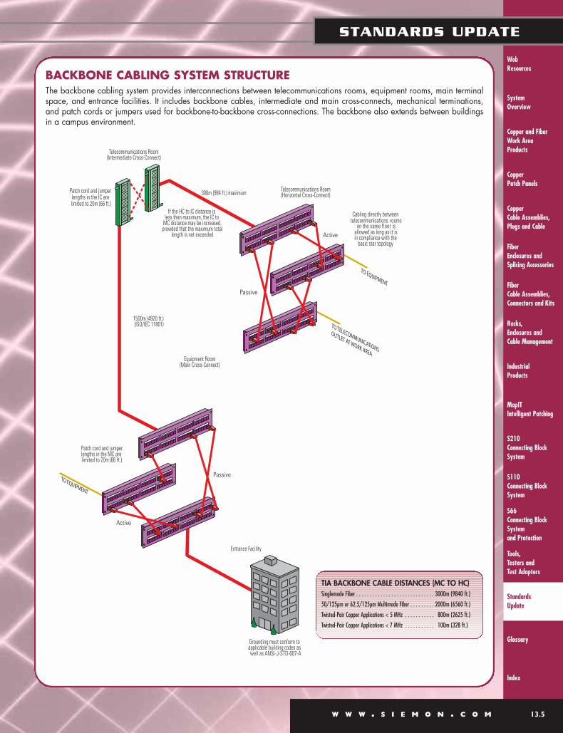
BACKBONE CABLING SYSTEM STRUCTUREThe backbone cabling system provides interconnections between telecommunications rooms, equipment rooms, main terminalspace, and entrance facilities. It includes backbone cables, intermediate and main cross-connects, mechanical terminations,and patch cords or jumpers used for backbone-to-backbone cross-connections. The backbone also extends between buildingsin a campus environment.
TIA BACKBONE CABLE DISTANCES (MC TO HC)Singlemode Fiber . . . . . . . . . . . . . . . . . . . . . . . . . . . . . 3000m (9840 ft.)
50/125µm or 62.5/125µm Multimode Fiber . . . . . . . . . 2000m (6560 ft.)
Twisted-Pair Copper Applications < 5 MHz . . . . . . . . . . . 800m (2625 ft.)
Twisted-Pair Copper Applications < 7 MHz . . . . . . . . . . . 100m (328 ft.)
System Overview
Racks, Enclosures and
Cable Management
MapITIntelligent Patching
S110Connecting Block
System
Tools, Testers and
Test Adapters
Glossary
Index
Industrial Products
S210Connecting Block
System
S66 Connecting Block
Systemand Protection
Web Resources
Copper and FiberWork Area
Products
Copper Patch Panels
Copper Cable Assemblies,
Plugs and Cable
13.6 W W W . S I E M O N . C O M
STANDARDS UPDATE
Fiber Enclosures and
Splicing Accessories
Fiber Cable Assemblies,
Connectors and Kits
Standards Update
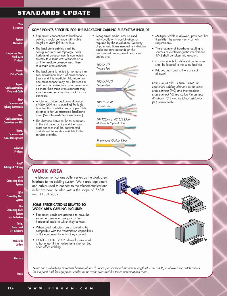
SOME POINTS SPECIFIED FOR THE BACKBONE CABLING SUBSYSTEM INCLUDE:
WORK AREAThe telecommunications outlet serves as the work areainterface to the cabling system. Work area equipmentand cables used to connect to the telecommunicationsoutlet are now included within the scope of ’568-B.1and ’11801:2002.
• Equipment connections to backbonecabling should be made with cablelengths of 30m (98 ft.) or less.
• The backbone cabling shall be configured in a star topology. Each horizontal cross-connect is connecteddirectly to a main cross-connect or to an intermediate cross-connect, then to a main cross-connect.
• The backbone is limited to no more thantwo hierarchical levels of cross-connects(main and intermediate). No more thanone cross-connect may exist between amain and a horizontal cross-connect andno more than three cross-connects mayexist between any two horizontal cross-connects.
• A total maximum backbone distance of 90m (295 ft.) is specified for highbandwidth capability over copper. Thisdistance is for uninterrupted backboneruns. (No intermediate cross-connect).
• The distance between the terminations in the entrance facility and the maincross-connect shall be documented and should be made available to theservice provider.
• Recognized media may be usedindividually or in combination, asrequired by the installation. Quantity of pairs and fibers needed in individualbackbone runs depends on the area served. Recognized backbonecables are:
• Multi-pair cable is allowed, provided thatit satisfies the power sum crosstalkrequirements.
• The proximity of backbone cabling tosources of electromagnetic interference(EMI) shall be taken into account.
• Cross-connects for different cable typesshall be located in the same facilities.
• Bridged taps and splitters are notallowed.
Notes: In ISO/IEC 11801:2002, the equivalent cabling elements to the maincross-connect (MC) and intermediate cross-connect (IC) are called the campusdistributor (CD) and building distributor(BD) respectively.
SOME SPECIFICATIONS RELATED TOWORK AREA CABLING INCLUDE:
• Equipment cords are assumed to have thesame performance category as thehorizontal cable to which they connect.
• When used, adapters are assumed to becompatible with the transmission capabilitiesof the equipment to which they connect.
• ISO/IEC 11801:2002 allows for any cordto be longer if the horizontal is shorter. Seeopen office cabling.
Note: For establishing maximum horizontal link distances, a combined maximum length of 10m (33 ft.) is allowed for patch cables (or jumpers) and for equipment cables in the work area and the telecommunications room.
100 Ω UTP Twisted-Pair
100 Ω F/UTP Twisted-Pair
100 Ω S/FTP Twisted-Pair
50/125µm or 62.5/125µm Multimode Optical Fiber
Singlemode Optical Fiber

System Overview
Racks, Enclosures and Cable Management
MapITIntelligent Patching
S110Connecting BlockSystem
Tools, Testers and Test Adapters
Glossary
Index
Industrial Products
Web Resources
W W W . S I E M O N . C O M 13.7
STANDARDS UPDATE
S210Connecting BlockSystem
S66 Connecting BlockSystemand Protection
Copper and FiberWork Area Products
Copper Patch Panels
Copper Cable Assemblies, Plugs and Cable
Fiber Enclosures andSplicing Accessories
Fiber Cable Assemblies,Connectors and Kits
Standards Update
OPEN OFFICE CABLINGAdditional specifications for horizontal cabling in areas with moveable furniture and partitions have been included in TIA/EIA-568-B.1. Horizontal cabling methodologies are specified for “open office” environments by means of multi-usertelecommunications outlet assemblies and consolidation points. These methodologies are intended to provide increasedflexibility and economy for installations with open office work spaces that require frequent reconfiguration.
THIS IS AN EXAMPLE OF OPEN OFFICE IMPLEMENTATION USING THEMuTOA — MULTI-USER TELECOMMUNICATIONS OUTLET ASSEMBLYMuTOA: A telecommunications outlet scheme intended to serve multiple workareas in an open office environment.
THIS IS AN EXAMPLE OF OPEN OFFICE IMPLEMENTATION USING A CONSOLIDATION POINT CONNECTORConsolidation Point: An interconnection scheme that connects horizontal cables from building pathways to cables that extend toTOs through open office pathways.
Note: To reduce the effects of multiple connectionsin close proximity, the CP should be located atleast 15m (50 ft.) from the HC (FD).

System Overview
Racks, Enclosures and
Cable Management
MapITIntelligent Patching
S110Connecting Block
System
Tools, Testers and
Test Adapters
Glossary
Index
Industrial Products
S210Connecting Block
System
S66 Connecting Block
Systemand Protection
Web Resources
Copper and FiberWork Area
Products
Copper Patch Panels
Copper Cable Assemblies,
Plugs and Cable
13.8 W W W . S I E M O N . C O M
STANDARDS UPDATE
Fiber Enclosures and
Splicing Accessories
Fiber Cable Assemblies,
Connectors and Kits
Standards Update
LENGTH OF MAXIMUM LENGTH MAXIMUM LENGTHHORIZONTAL CABLE OF WORK AREA CABLE OF WORK AREA CABLE
24 AWG (20%) 26 AWG (50%)
H W Wm (ft.) m (ft.) m (ft.)
90 (295) 5 (16) 4 (13)
85 (279) 9 (30) 7 (23)
80 (262) 13 (44) 11 (35)
75 (246) 17 (57) 14 (46)
70 (230) 22 (72) 17 (56)
HORIZONTAL DISTANCES OF COPPER LINKS (OPEN OFFICE)The table entries assume that there is a total of 5m (16 ft.) of patch and equipment cables in the telecommunications room. Table 1 shows the application of these formulae assuming the use of 24 AWG cable. The length of work area cables shall notexceed 22m (72 ft.) per TIA/EIA 568-B, 20m (66 ft.) per ISO/IEC 11801:2002. The MuTOA shall be marked with themaximum allowable work area cable length.
HORIZONTAL DISTANCES OF OPTICAL FIBER LINKS (LONG WORK AREA CABLES)For optical fiber cables, any length combination of horizontal cables and work area cables is acceptable, as long as the total combined length of the horizontal channel does not exceed 100m (328 ft.). When deploying a centralized fiber cablingtopology, the general guidelines of 568-B.1 shall be followed.
ADVANTAGES AND FEATURES• It is preferable to use MuTOAs only when the entire length of
the work area cord is accessible to facilitate tracing and toprevent erroneous disconnection. Up to 22m (72 ft.) of workarea cable is allowed.
• MuTOAs are subject to the same interface requirementsspecified for each media type.
• Consolidation point requirements are performance based. Thereis no physical interface requirement for the CP except thoserequired to meet functional requirements.
.• Implementations using either MuTOAs or CPs are subject to thesame end-to-end performance requirements.
• Consolidation points have advantage in that they deliverdedicated TOs to individual work areas and do not requireprovisions for extended cord lengths.
*Note: The preceding equation and table are based on patch cables having 20% more attenuation than horizontal cables. If higher gauge (e.g. 26 AWG) cables are used that have 50% higher attenuation than solid, as allowed by ISO/IEC 11801:2002, these lengths must be reduced accordingly.
TABLE 1 — MAXIMUM LENGTH OF WORK AREA CABLE
System Overview
Racks, Enclosures and Cable Management
MapITIntelligent Patching
S110Connecting BlockSystem
Tools, Testers and Test Adapters
Glossary
Index
Industrial Products
Web Resources
W W W . S I E M O N . C O M 13.9
STANDARDS UPDATE
S210Connecting BlockSystem
S66 Connecting BlockSystemand Protection
Copper and FiberWork Area Products
Copper Patch Panels
Copper Cable Assemblies, Plugs and Cable
Fiber Enclosures andSplicing Accessories
Fiber Cable Assemblies,Connectors and Kits
Standards Update
TELECOMMUNICATIONS ROOMTelecommunications Rooms (TR) are generally considered to be floor serving facilities for horizontal cable distribution. They mayalso be used for intermediate and main cross-connects.
SOME SPECIFICATIONS RELATED TO THE TELECOMMUNICATIONS ROOM:
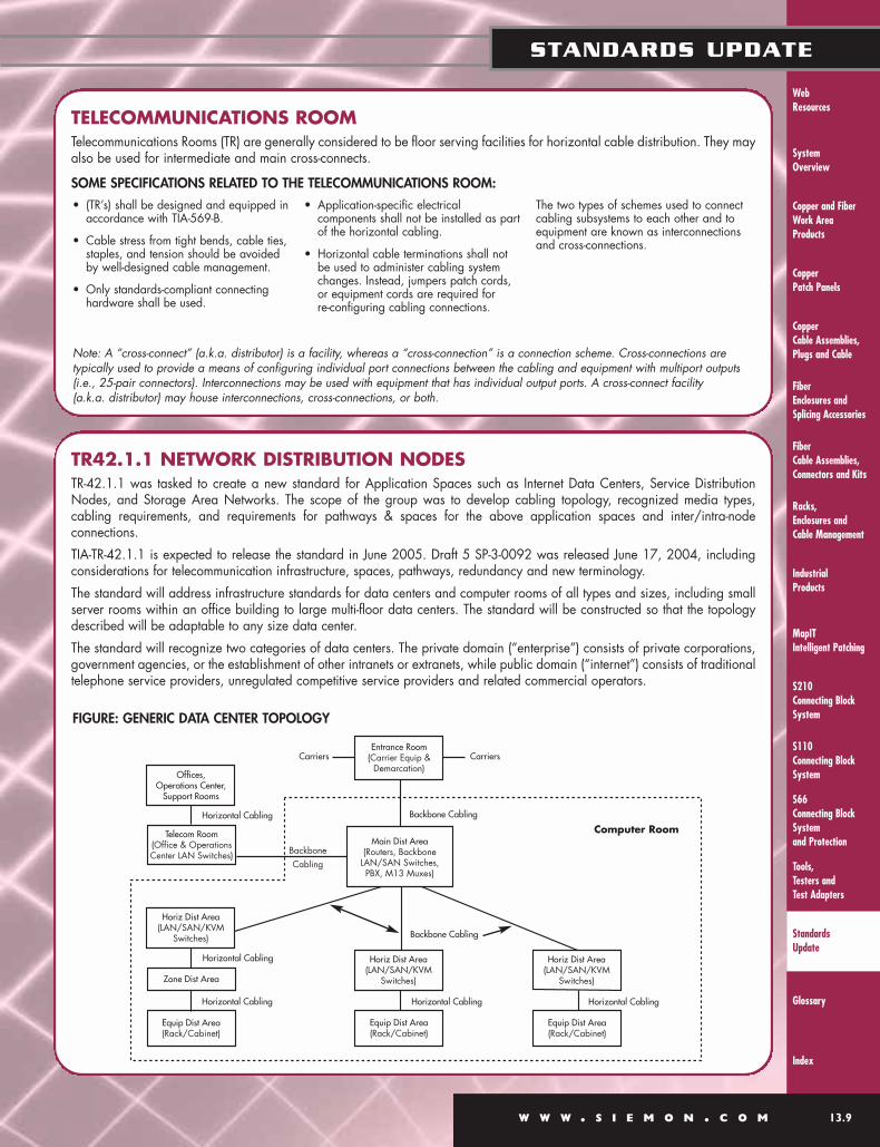
TR42.1.1 NETWORK DISTRIBUTION NODESTR-42.1.1 was tasked to create a new standard for Application Spaces such as Internet Data Centers, Service DistributionNodes, and Storage Area Networks. The scope of the group was to develop cabling topology, recognized media types,cabling requirements, and requirements for pathways & spaces for the above application spaces and inter/intra-nodeconnections.
TIA-TR-42.1.1 is expected to release the standard in June 2005. Draft 5 SP-3-0092 was released June 17, 2004, includingconsiderations for telecommunication infrastructure, spaces, pathways, redundancy and new terminology.
The standard will address infrastructure standards for data centers and computer rooms of all types and sizes, including smallserver rooms within an office building to large multi-floor data centers. The standard will be constructed so that the topologydescribed will be adaptable to any size data center.
The standard will recognize two categories of data centers. The private domain (“enterprise”) consists of private corporations,government agencies, or the establishment of other intranets or extranets, while public domain (“internet”) consists of traditionaltelephone service providers, unregulated competitive service providers and related commercial operators.
• (TR’s) shall be designed and equipped inaccordance with TIA-569-B.
• Cable stress from tight bends, cable ties,staples, and tension should be avoidedby well-designed cable management.
• Only standards-compliant connectinghardware shall be used.
• Application-specific electricalcomponents shall not be installed as partof the horizontal cabling.
• Horizontal cable terminations shall notbe used to administer cabling systemchanges. Instead, jumpers patch cords,or equipment cords are required for re-configuring cabling connections.
The two types of schemes used to connectcabling subsystems to each other and toequipment are known as interconnectionsand cross-connections.
FIGURE: GENERIC DATA CENTER TOPOLOGY
Carriers Carriers
Computer Room
Entrance Room(Carrier Equip &
Demarcation)
Main Dist Area(Routers, Backbone
LAN/SAN Switches, PBX, M13 Muxes)
Horiz Dist Area(LAN/SAN/KVM
Switches)
Equip Dist Area(Rack/Cabinet)
Horizontal Cabling
Horiz Dist Area(LAN/SAN/KVM
Switches)
Equip Dist Area(Rack/Cabinet)
Horizontal Cabling
Horiz Dist Area(LAN/SAN/KVM
Switches)
Zone Dist Area
Horizontal Cabling
Equip Dist Area(Rack/Cabinet)
Horizontal Cabling
Backbone Cabling
Backbone Cabling
Offices, Operations Center,
Support Rooms
Telecom Room(Office & Operations Center LAN Switches)
Horizontal Cabling
Backbone Cabling
Note: A “cross-connect” (a.k.a. distributor) is a facility, whereas a “cross-connection” is a connection scheme. Cross-connections are typically used to provide a means of configuring individual port connections between the cabling and equipment with multiport outputs(i.e., 25-pair connectors). Interconnections may be used with equipment that has individual output ports. A cross-connect facility (a.k.a. distributor) may house interconnections, cross-connections, or both.
System Overview
Racks, Enclosures and
Cable Management
MapITIntelligent Patching
S110Connecting Block
System
Tools, Testers and
Test Adapters
Glossary
Index
Industrial Products
S210Connecting Block
System
S66 Connecting Block
Systemand Protection
Web Resources
Copper and FiberWork Area
Products
Copper Patch Panels
Copper Cable Assemblies,
Plugs and Cable
13.10 W W W . S I E M O N . C O M
STANDARDS UPDATE
Fiber Enclosures and
Splicing Accessories
Fiber Cable Assemblies,
Connectors and Kits
Standards Update
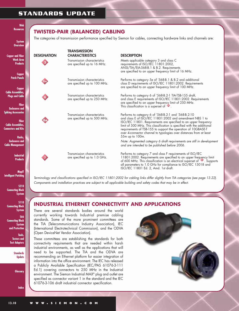
INDUSTRIAL ETHERNET CONNECTIVITY AND APPLICATIONSThere are several standards bodies around the worldcurrently working towards Industrial premise cablingstandards. Some of the more prominent committees are the TIA (Telecommunications Industry Association), IEC(International Electrotechnical Commission), and the ODVA(Open DeviceNet Vendor Association).
These committees are establishing the standards for bothconnectivity requirements that are needed within harshindustrial environments, as well as the applications that willneed to be supported. The TIA and the ODVA arerecommending an Ethernet platform for easier integration ofinformation into the office environment. The IEC has releaseda Publicly Available Specification (IEC/PAS 61076-3-111Ed.1) covering connectors to 250 MHz in the Industrialenvironment. The Siemon Industrial MAX® plug and outlet arespecified as connector variant 1 in the standard and the IEC61076-3-106 draft industrial connector specification.
TWISTED-PAIR (BALANCED) CABLINGThe categories of transmission performance specified by Siemon for cables, connecting hardware links and channels are:
TRANSMISSION DESIGNATION CHARACTERISTICS DESCRIPTION
Transmission characteristics Meets applicable category 3 and class C are specified up to 16 MHz. requirements of ISO/IEC 11801:2002,
ANSI/TIA/EIA-568-B.1 & B.2. Requirements are specified to an upper frequency limit of 16 MHz.
Transmission characteristics Performs to category 5e of ’568-B.1 & B.2 and additional are specified up to 100 MHz. class D requirements of ISO/IEC 11801:2002. Requirements
are specified to an upper frequency limit of 100 MHz.
Transmission characteristics Performs to category 6 of ’568-B.2-1 TIA-TSB-155 draft, are specified up to 250 MHz. and class E requirements of ISO/IEC 11801:2002. Requirements
are specified to an upper frequency limit of 250 MHz. This classification is a superset of .
Transmission characteristics Performs to category 6 of ’568-B.2-1 and ’568-B.2-10 are specified up to 500 MHz. and class E of ISO/IEC 11801:2002 and amendment NBS 1 to
ISO/IEC 11801. Requirements are specified to an upper frequency limit of 500 MHz. This classification is specified with the additionalrequirements of TSB-155 to support the operation of 10GBASE-T over 4-connector channel to typologies over distances from at least 55m up to 100m.Note: Augmented category 6 draft requirements are still in developmentand are intended to be published before 2006.
Transmission characteristics Performs to category 7 and class F requirements of ISO/IEC are specified up to 1.0 GHz. 11801:2002. Requirements are specified to an upper frequency limit
of 600 MHz. This classification is an electrical superset of . Supportsall parameters to 1.0 GHz for compliance to ISO/IEC 15018 andISO/IEC 11801 Ed. 2, Amd. 1st draft.
Terminology and classifications specified in ISO/IEC 11801:2002 for cabling links differ slightly from TIA categories (see page 13.22).Components and installation practices are subject to all applicable building and safety codes that may be in effect.
System Overview
Racks, Enclosures and Cable Management
MapITIntelligent Patching
S110Connecting BlockSystem
Tools, Testers and Test Adapters
Glossary
Index
Industrial Products
Web Resources
W W W . S I E M O N . C O M 13.11
STANDARDS UPDATE
S210Connecting BlockSystem
S66 Connecting BlockSystemand Protection
Copper and FiberWork Area Products
Copper Patch Panels
Copper Cable Assemblies, Plugs and Cable
Fiber Enclosures andSplicing Accessories
Fiber Cable Assemblies,Connectors and Kits
Standards Update
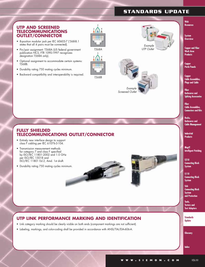
UTP AND SCREENEDTELECOMMUNICATIONSOUTLET/CONNECTOR• 8-position modular jack per IEC 60603-7 (’568-B.1
states that all 4 pairs must be connected).
• Pin/pair assignment: T568A (US federal government publication NCS, FTR 1090-1997 recognizes designation T568A only).
• Optional assignment to accommodate certain systems:T568B.
• Durability rating 750 mating cycles minimum.
• Backward compatibility and interoperability is required.
FULLY SHIELDED TELECOMMUNICATIONS OUTLET/CONNECTOR• Entirely new interface design to support
class F cabling per IEC 61076-3-104.
• Transmission measurement methods for category 7 and class F specified by ISO/IEC 11801:2002 and 1.0 GHz per ISO/IEC 15018 and ISO/IEC 11801 Ed.2, Amd. 1st draft.
• Durability rating 750 mating cycles minimum.
UTP LINK PERFORMANCE MARKING AND IDENTIFICATION• Link category marking should be clearly visible on both ends (component markings are not sufficient).
• Labeling, markings, and color-coding shall be provided in accordance with ANSI/TIA/EIA-606-A.
3
2
4
T568A
2
3
4
T568B
Example UTP Outlet
Example Screened Outlet
1
1

System Overview
Racks, Enclosures and
Cable Management
MapITIntelligent Patching
S110Connecting Block
System
Tools, Testers and
Test Adapters
Glossary
Index
Industrial Products
S210Connecting Block
System
S66 Connecting Block
Systemand Protection
Web Resources
Copper and FiberWork Area
Products
Copper Patch Panels
Copper Cable Assemblies,
Plugs and Cable
13.12 W W W . S I E M O N . C O M
STANDARDS UPDATE
Fiber Enclosures and
Splicing Accessories
Fiber Cable Assemblies,
Connectors and Kits
Standards Update
SCREENED CABLING (F/UTP)As a result of the release of TIA/EIA/IS-729 and the maturity of the ’568-B and’11801:2002 standards, telecommunications groups recognize the presence of an overallshield over four twisted-pairs; a media termed Screened Twisted-Pair. This cabling type isrecognized as F/UTP, which stands for a foil applied over unshielded twisted-pairs.
FULLY SHIELDED CABLING (S/FTP)Fully shielded cabling requirements have been developed by ISO and IEC. Cable andconnector specifications extend to 600 MHz and support class F cabling requirements. (AnISO/IEC project has been started to create amendment 1 of Ed. 2 of ISO/IEC 11801,which extends class F to 1.0 GHz). This cabling type is recognized as S/FTP, which standsfor a foil and braided overall shield applied over individually foil shielded twisted-pairs.
F/UTP CABLE:• Color-coding:
Pair 1 = White/Blue – BluePair 2 = White/Orange – OrangePair 3 = White/Green – GreenPair 4 = White/Brown – Brown
• 0.51mm (24 AWG) 100 Ω 4-pair enclosed by a foil shield.• A copper conductor drain wire of .040mm (26 AWG)
or larger shall be provided.• Should be marked “100 Ω ScTP” or “100 Ω F/UTP”, in
addition to any safety markings required by local or nationalcodes.
• Same mechanical and transmission requirements apply to backbone and horizontal cables.
• Additional performance requirements, including surface transfer impedance, is specified in TIA/EIA-568-B.2 and ISO/IEC 11801:2002.
SCREENED CONNECTORS:• Interface and pair assignments same as IEC 60603-7
(’568-B.1 states that all 4 pairs must be connected).• Additional transfer impedance and shield mating interface
requirements specified in IEC 60603-7-3 and IEC 60603-7-5.
F/UTP PATCH CORDS:• Specifications call for 26 AWG (7 strands @ 0.15mm)
or 24 AWG (7 strands @ 0.20mm) stranded conductors.• Allows for an overall shield.• Allows for 50% more attenuation than horizontal cable.
F/UTP INSTALLATION PRACTICES:• Shield shall be bonded at both ends at the “Telecommunication
Grounding Busbar”.• The difference between the two grounds shall be no more
than 1.0 V RMS.
FULLY SHIELDED CABLE:• Color-coding:
Pair 1 = White/Blue – BluePair 2 = White/Orange – OrangePair 3 = White/Green – GreenPair 4 = White/Brown – Brown
• Four 0.51mm (24 AWG) or larger 100 Ω twisted-pairs each enclosed by an individual foil shield with an overall shield provided over the four-pairs.
• Mechanical and transmission requirements developed by ISO and IEC.
FULLY SHIELDED CONNECTORS:• Cabling interface and pair assignments specified by ISO/IEC
11801:2002. • Mechanical and transmission requirements specified in IEC
60603-7-7 and IEC/PAS 61076-3-104.
FULLY SHIELDED PATCH CABLES:• Mechanical and transmission requirements are specified in IEC
61156-5 and IEC 61156-6.
FULLY SHIELDED INSTALLATION PRACTICES:• Installation Practices developed by ISO/IEC.
INTERCONNECTA connection scheme thatprovides for direct connectionsto building cabling from equip-ment without a patch cord.
CROSS-CONNECTA connection scheme usingpatch cords or jumpers thatattach to connecting hardwareon each end.

System Overview
Racks, Enclosures and Cable Management
MapITIntelligent Patching
S110Connecting BlockSystem
Tools, Testers and Test Adapters
Glossary
Index
Industrial Products
Web Resources
W W W . S I E M O N . C O M 13.13
STANDARDS UPDATE
S210Connecting BlockSystem
S66 Connecting BlockSystemand Protection
Copper and FiberWork Area Products
Copper Patch Panels
Copper Cable Assemblies, Plugs and Cable
Fiber Enclosures andSplicing Accessories
Fiber Cable Assemblies,Connectors and Kits
Standards Update
TRANSMISSION PERFORMANCE SPECIFICATIONS FOR FIELD TESTING OF BALANCED CABLING SYSTEMSThis document provides users with the opportunity to use comprehensive test methods to validate the transmission performancecharacteristics of installed category 7, 6, 5e and lower grade twisted-pair cabling systems. The categories of balanced cablingsystems in this bulletin correspond with the balanced cabling categories of ANSI/TIA/EIA-568-B.1, ANSI/TIA/EIA-568-B.2-1,and ISO/IEC 11801:2002.
SOME POINTS SPECIFIED FOR TRANSMISSION FIELD TESTING FOR TWISTED-PAIR CABLING SYSTEMS:
• Twisted-Pair cabling systems are comprised of cables and connecting hardware specified in TIA/EIA-568-B.2 and ISO/IEC 11801:2002.
• Required test parameters include wire-map, length, insertion loss, and pair-to-pair NEXT loss, powersum NEXT loss, ELFEXT, powersum. ELFEXT, return loss, propagation delay, and delay skew.
• Two levels of pass or fail are indicated, depending on measured margin compared to minimum specifications. Testing of NEXT loss is required in both directions.
• Requirements are intended for performance validation and are provided in addition to ’568-B.1 & B.2 requirements oncomponents and installation practices. Level III field testaccuracy required for category 6/class E.
HORIZONTAL CHANNEL (COPPER) Performance Specified in:TIA/EIA-568-B.1 (category 5e), TIA/EIA-568-B.2-1 (category 6), andproposed TIA/EIA-568-B.2-10 (augmented category 6)ISO/IEC 11801:2002 2nd Edition (classes D, E and F) and proposedamendment 1 to ISO/IEC 11801:2002
TRANSMISSION PERFORMANCE COMPARISON @ 100 MHZ
Cabling Type Channel Channel Channel Channel ChannelInsertion Loss NEXT ELFEXT Return Loss *ACR
(dB) (dB) (dB) (dB) (dB)
Category 5e/Class D (@ 100 MHz) 24.0 30.1 17.4 10.0 6.1
Category 6/Class E (@ 100 MHz) 21.7 39.9 23.3 12.0 18.2
Class 7/Class F (@ 100 MHz) 20.8 62.9 44.4 12.0 42.1
Cabling Type Permanent Link Permanent Link Permanent Link Permanent Link Permanent LinkInsertion Loss NEXT ELFEXT Return Loss *ACR
(dB) (dB) (dB) (dB) (dB)
Category 5e/Class D (@ 100 MHz) 20.4 32.3 18.6 12.0 11.9
Category 6/Class E (@ 100 MHz) 18.5 41.8 24.2 14.0 23.3
Class 7/Class F (@ 100 MHz) 17.7 65.0 46.0 14.0 47.3
*Not specified by TIAClass D attenuation values are calculated based on 90 meters horizontal cable plus two connectors (no flexible cord contribution) that meet ISO/IEC 11801:2002. Class D NEXT values are based on voltage summation of the near-end connector and horizontal cable.
Field tester cords are electricallycancelled from test
*Not specified by TIA
LINK TEST CONFIGURATION Performance Specified in: TIA/EIA-568-B.1 (category 5e), TIA/EIA-568-B.2-1 (category 6), andproposed TIA/EIA-568-B.2-10 (augmented category 6)ISO/IEC 11801:2002 2nd Edition (classes D, E and F) and proposedamendment to ISO/IEC 11801’2002
TRANSMISSION PERFORMANCE COMPARISON @ 100 MHZ
System Overview
Racks, Enclosures and
Cable Management
MapITIntelligent Patching
S110Connecting Block
System
Tools, Testers and
Test Adapters
Glossary
Index
Industrial Products
S210Connecting Block
System
S66 Connecting Block
Systemand Protection
Web Resources
Copper and FiberWork Area
Products
Copper Patch Panels
Copper Cable Assemblies,
Plugs and Cable
13.14 W W W . S I E M O N . C O M
STANDARDS UPDATE
Fiber Enclosures and
Splicing Accessories
Fiber Cable Assemblies,
Connectors and Kits
Standards Update
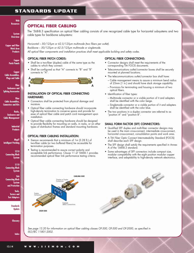
OPTICAL FIBER PATCH CORDS:• Shall be a two-fiber (duplex) cable of the same type as the
cables to which they connect.• Shall be configured so that “A” connects to “B” and “B”
connects to “A”.
INSTALLATION OF OPTICAL FIBER CONNECTINGHARDWARE:• Connectors shall be protected from physical damage and
moisture.• Optical fiber cable connecting hardware should incorporate
high-density termination to conserve space and provide for ease of optical fiber cable and patch cord management uponinstallation.
• Optical fiber cable connecting hardware should be designed to provide flexibility for mounting on walls, in racks, or on othertypes of distribution frames and standard mounting hardware.
OPTICAL FIBER CABLING INSTALLATION:• Siemon recommends that a minimum of 1m (3.28 ft.) of
two-fiber cable (or two buffered fibers) be accessible fortermination purposes.
• Testing is recommended to assure correct polarity and acceptable link performance. Clause 11 of ’568-B.1 providesrecommended optical fiber link performance testing criteria.
OPTICAL FIBER CONNECTIONS:• Connector designs shall meet the requirements of the
corresponding TIA FOCIS documents.• Telecommunications outlet/connector boxes shall be securely
mounted at planned locations.• The telecommunications outlet/connector box shall have:
– Cable management means to assure a minimum bend radiusof 25mm (1 in.) and should have slack storage capability.
– Provisions for terminating and housing a minimum of twooptical fibers.
• Identification of fiber types: – Multimode connector or a visible portion of it and adapters
shall be identified with the color beige.– Singlemode connector or a visible portion of it and adapters
shall be identified with the color blue.• The two positions in a duplex connector are referred to as
“position A” and “position B”.
SMALL FORM FACTOR (SFF) CONNECTORS:• Qualified SFF duplex and multi-fiber connector designs may
be used in the main cross-connect, intermediate cross-connect,horizontal cross-connect, consolidation points and work area.
• A TIA Fiber Optic Connect Intermateability Standard (FOCIS)shall describe each SFF design.
• The SFF design shall satisfy the requirements specified in AnnexA of the ’568-B.3 standard.
• Some advantages of SFF connectors include compact size, modular compatibility with the eight position modular copperinterface, and adaptability to high-density network electronics.
A
AB
B
See page 13.20 for information on optical fiber cabling classes OF-300, OF-500 and OF-2000, as specified in ISO/IEC 11801:2002.
OPTICAL FIBER CABLINGThe ’568-B.3 specification on optical fiber cabling consists of one recognized cable type for horizontal subsystems and twocable types for backbone subsystems:
Horizontal – 50/125µm or 62.5/125µm multimode (two fibers per outlet).Backbone – 50/125µm or 62.5/125µm multimode or singlemode.All optical fiber components and installation practices shall meet applicable building and safety codes.

System Overview
Racks, Enclosures and Cable Management
MapITIntelligent Patching
S110Connecting BlockSystem
Tools, Testers and Test Adapters
Glossary
Index
Industrial Products
Web Resources
W W W . S I E M O N . C O M 13.15
STANDARDS UPDATE
S210Connecting BlockSystem
S66 Connecting BlockSystemand Protection
Copper and FiberWork Area Products
Copper Patch Panels
Copper Cable Assemblies, Plugs and Cable
Fiber Enclosures andSplicing Accessories
Fiber Cable Assemblies,Connectors and Kits
Standards Update
568-B.1 AND ISO/IEC 11801:2002CENTRALIZED OPTICAL FIBER CABLING:
Centralized optical fiber cabling provides the user with the flexibility of designing an optical fiber cabling system for centralizedelectronics in single tenant buildings. It contains information and guidelines for design and installation requirements.
TYPICAL SCHEMATIC FOR CENTRALIZED OPTICAL FIBER CABLING USING AN INTERCONNECTION
• Intended for single-tenant users whodesire centralized vs. distributed electronics.
• Implementation allows cables to bespliced or interconnected at the telecommunications room such thatcables can be routed to a centralizeddistributor for total channel lengths of 300m (984 ft.) or less, including patch cords or jumpers.
• Allows for migration from aninterconnection or splice to a cross-connection scheme that can also supportdistributed electronics.
• Pull-through implementations areallowed when total length between the telecommunications outlet/connectorand centralized cross-connect is 90m(295 ft.) or less.
• Connecting hardware required to:– join fibers by re-mateable
connectors or splices,– provide for simplex or duplex
connection of optical fibers,– provide means of circuit identification,– allow for addition and removal of
optical fibers.
SOME POINTS SPECIFIED FOR A CENTRALIZED OPTICAL FIBER CABLING SYSTEM INCLUDE:
Note: Some multimode fiber implementations may be limited to an operating range of 220m to support 1000BASE-SX.The use of laser optimized 50 micon multimode fiber is required to support 300m of 10GBASE-SX.

HYBRID AND BUNDLED CABLESAs a result of the demand for open office architecture and the need tosupport multiple telecommunications applications in a shared sheath,performance specifications for hybrid cables have been revised. A newterm called “bundled cables” has been introduced to describe 4-paircable assemblies that are not covered by an overall sheath (as specifiedfor hybrid cables), but by any generic binding method such as “speed-wrap” or “cable-ties.”
The new hybrid and bundled cable requirements state that power sumNEXT loss between all non-fiber cable types within the cable shall be 3dB better than the specified pair-to-pair NEXT loss for each cable type.See figure 1.
FIGURE 1:Pair-to-Pair measurements required to calculate powersum NEXT loss for pair 1 of a 24-pair hybrid cable.
PRODUCTION MODULAR CORD NEXT LOSS TEST METHOD AND REQUIREMENTS FOR UNSHIELDED TWISTED PAIR CABLINGTIA/EIA-568-B.2 and TIA/EIA-568-B.2-1 defines a generic and non-destructivemethodology for NEXT loss testing of modular plug cords respectively. The methodologydescribed in the Standard contains the detailed NEXT loss calculations (which are basedupon patch cable NEXT loss, test head NEXT loss, and cable and connector attenuation contributions) for the determination of the NEXT loss limits for any category 5e (TIA/EIA-588-B.2) or category 6 (TIA/EIA-568-B.2-1) patch cord and suitably designedtest head.
CROSSTALK NOISENEXT — Near-end Crosstalk — Signal coupling between pairs in the samecable when the disturbing signal is sent from the same end as the receiver.
FEXT — Far-end Crosstalk — Signal coupling between pairs in the same cablewhen the disturbing signal is sent from the opposite end as the receiver.
Alien Crosstalk — A measure of the unwanted signal coupling between pairs inadjacent cabling.
Power Sum Alien Crosstalk — A combination of the unwanted signal cablingbetween all pairs in adjacent cabling.
Near-end Crosstalk Alien Crosstalk Far-end Crosstalk
System Overview
Racks, Enclosures and
Cable Management
MapITIntelligent Patching
S110Connecting Block
System
Tools, Testers and
Test Adapters
Glossary
Index
Industrial Products
S210Connecting Block
System
S66 Connecting Block
Systemand Protection
Web Resources
Copper and FiberWork Area
Products
Copper Patch Panels
Copper Cable Assemblies,
Plugs and Cable
13.16 W W W . S I E M O N . C O M
STANDARDS UPDATE
Fiber Enclosures and
Splicing Accessories
Fiber Cable Assemblies,
Connectors and Kits
Standards Update

System Overview
Racks, Enclosures and Cable Management
MapITIntelligent Patching
S110Connecting BlockSystem
Tools, Testers and Test Adapters
Glossary
Index
Industrial Products
Web Resources
W W W . S I E M O N . C O M 13.17
STANDARDS UPDATE
S210Connecting BlockSystem
S66 Connecting BlockSystemand Protection
Copper and FiberWork Area Products
Copper Patch Panels
Copper Cable Assemblies, Plugs and Cable
Fiber Enclosures andSplicing Accessories
Fiber Cable Assemblies,Connectors and Kits
Standards Update
ISO/IEC 11801:2002 2ND EDITION The performance specifications in ISO/IEC11801:2002 2nd Edition provide new requirements for return loss and ELFEXT lossto complement the existing ISO class D requirements. The new specified return loss and ELFEXT loss requirements are in harmonywith the values in ’568-B.1 & B.2. The 2nd Edition of ’11801 also includes propagation delay and delay skew requirementsfor channels and permanent links that are in harmony with the requirements of TIA/EIA-568-B.1.
The requirements of the 2nd Edition to ISO/IEC 11801 are normative and this document has become the governinginternational standard for cabling installations.
The first amendment to ISO/IEC 11801:2002 is being drafted and includes increasing class F/category 7 frequency range to1.0 GHz. The first amendment to IEC 61076-3-104 is also being drafted and will be increased to 1.0 GHz to support theISO/IEC 11801 amendment.
NEXT GENERATION CABLING
CATEGORY 6/CLASS E (’568-B.2-1 AND ’11801:2002)Category 6/class E standards describe a new performance range for unshielded and screened twisted-pair cabling.Category 6/class E specifies the best performance that UTP and F/UTP (screened) cabling solutions can be designed todeliver based on current technology. Category 6/class E is specified in the frequency range of at least 1-250 MHz. Forcategory 6/class E, the 8-position modular jack interface will be mandatory at the work area. Category 6/class E isbackward compatible meaning that applications running on lower categories/classes will also be supported. If differentcategory/class components are to be mixed with category 6/class E components, the combination shall meet thetransmission requirements of the lowest performing category/class component.
TIA, ISO, CENELEC, and others have collaborated closely on the development of category 6 and class E standards andtheir requirements are well harmonized.
Augmented category 6/Class E, Edition 2.1 (proposed TIA/EIA 568-B.2-10) and amendments 1 to ISO/IEC 118012002. This standard will document the additional requirements necessary to support the operation of 10GBASE-T over100-meter, 4-connector augmented category 6 and class E, edition 2.1 cabling.
Note: Augmented category 6 draft requirements are still in development and are intended to be published in 2006.
CATEGORY 7/CLASS F (’11801:2002)Category 7/class F describes a new performance range for fully shielded (i.e., overall shield and individually shieldedpairs) twisted-pair cabling. Category 7/class F is specified in the frequency range of 1-600 MHz. Even though theserequirements are supported by a new interface design, category 7/class F will be backward compatible meaning thatapplications running on lower categories/classes will also be supported.
IEC 60603-7-7 and IEC/PAS 61076-3-104 specify two compliant interface designs. TIA is not actively developing astandard for category 7/class F.

System Overview
Racks, Enclosures and
Cable Management
MapITIntelligent Patching
S110Connecting Block
System
Tools, Testers and
Test Adapters
Glossary
Index
Industrial Products
S210Connecting Block
System
S66 Connecting Block
Systemand Protection
Web Resources
Copper and FiberWork Area
Products
Copper Patch Panels
Copper Cable Assemblies,
Plugs and Cable
13.18 W W W . S I E M O N . C O M
STANDARDS UPDATE
Fiber Enclosures and
Splicing Accessories
Fiber Cable Assemblies,
Connectors and Kits
Standards Update
STANDARDS UPDATEISO/IEC 15108 INFORMATION TECHNOLOGY — GENERIC CABLING FOR HOMES
This Standard recognizes the Siemon TERA® connector as an approved balanced cabling interface for all referenced homecabling communication applications. The specific home applications referenced in the Standard are:
Information and communications technology (ICT), Broadcast communications technologies (BCT), andCommands, controls and communication in buildings (CCCB).
The technical requirements of the Standard address cabling structure and topology, minimum configuration, link and channelperformance, interfaces, and coexistence with other services. A summary of key media and interface criteria is shown in thetable below:
Type of media:
Typical frequency range
Channel classes according toISO/IEC 11801:2002:
Interface at device:
ICT CABLING
Balanced cables, optical fibers
Up to 100 MHz
Class D
Balanced or optical fiberconnectors per ISO/IEC11801 Ed. 2.0
BCT CABLING
Balanced cables, coaxial cables
Up to 3 GHz
N/A
Balanced connector per IEC61076-3-104 (Siemon TERA)or coaxial connectors: IEC61169-2 or IEC 61169-24(“F type”) or
CCCB CABLING
Balanced cables
Up to 100 kHz
N/A
Fixed connection, CCCBconnector(s) includingbalanced or optical fiberconnectors per ISO/IEC11801 Ed. 2.0
While the IEC 61076-3-104 Siemon TERA interface isrecognized for use in all three home cabling applications, it isimportant to note that the TERA interface is the primarybalanced twisted-pair cabling interface recognized to supportBCT cabling applications. This connector is the mostrecognized commercially available interface for ISO/IECcategory 7/class F applications.
ISO/IEC TR 24704 INFORMATION TECHNOLOGYCUSTOMER PREMISES CABLING FOR WIRELESS ACCESSPOINTS
This Technical Report addresses planning considerations forfuture connection to wireless access points that supplement theexisting copper and fiber optic premises cabling systeminfrastructure specifications of ISO/IEC11801 Ed. 2.0.Specified infrastructure guidelines are intended to support anarray of coverage areas that form a wireless network gridwithin a building. The Report specifies ISO/IEC 11801compliant horizontal cabling design considerations andguidelines for wireless access planning in the following areas:• minimum configuration, structure and topology,• performance requirements for permanent links and channels,• coverage and location of telecommunications outlets,• interfaces to wireless access points, and• power delivery over balanced cabling.
It is important to note that information and guidance related tothe placement and security of wireless access points are notaddressed in the content of this Report, althoughrecommendations related to the placement oftelecommunications outlets (TOs) are provided to supportflexible deployment of wireless services.
IEC 61076-3-104 DETAIL SPECIFICATION FOR 8-WAY,SHIELDED FREE AND FIXED CONNECTORS FOR DATATRANSMISSIONS WITH FREQUENCIES UP TO 600 MHZMINIMUM
The IEC 61076-3-104 standard describes requirements for anon-RJ 45 category 7 telecommunications connectinghardware interface that is based on the TERA plug/outletinterface developed by Siemon. This represents the first timein history that a non-RJ style connector interface has beeninternationally standardized for four-pair connections in astructured cabling system.
During the interface selection process conducted by ISO/IEC,an independent panel was asked to judge six different non-RJ-style connector proposals. Based on forty-eight separatecriteria, including size, complexity, manufacturability, user-friendliness and transmission performance, the TERA interfacewas ranked the best overall choice for delivering thedemanding bandwidth specified in the Standard. This newinterface Standard was endorsed by eighteen countries andrepresents a significant achievement for structured cabling.The international support for approval of the TERA interfaceand its associated Standard confirms its status as a non-proprietary solution.
TIA/EIA-862 BUILDING AUTOMATION SYSTEMSCABLING STANDARD FOR COMMERCIAL BUILDINGS
Building automation encompasses control systems such assecurity and monitoring (i.e. CCTV), safety systems such asfire alarm, environmental conditioning systems such asheating, ventilation, and air conditioning (HVAC), and energymanagement systems such as internal and external lighting.The TIA/EIA-862 Standard specifies generic cabling

System Overview
Racks, Enclosures and Cable Management
MapITIntelligent Patching
S110Connecting BlockSystem
Tools, Testers and Test Adapters
Glossary
Index
Industrial Products
Web Resources
W W W . S I E M O N . C O M 13.19
STANDARDS UPDATE
S210Connecting BlockSystem
S66 Connecting BlockSystemand Protection
Copper and FiberWork Area Products
Copper Patch Panels
Copper Cable Assemblies, Plugs and Cable
Fiber Enclosures andSplicing Accessories
Fiber Cable Assemblies,Connectors and Kits
Standards Update
topology, architecture, design, installation practices, testprocedures, and coverage areas to support buildingautomation systems (BAS) used in commercial buildings.Since, historically, providers of these building automationservices specified their own proprietary equipment, cables,interface connections, and topology, this new Standard offersthe distinct advantage of being able to support multi-productand multi-vendor environments using one generic structuredcabling system.
It is important to note that other “low voltage systems” (e.g.,audio/video paging, service/equipment alarms, non-voice/data communications, wireless access points) are alsosupported by the telecommunications cabling infrastructurerequirements of this Standard.
IEEE 802.3AF POWER OVER ETHERNET
This Standard was approved for publication in June of 2003and describes means to economically provide power over atwisted-pair link segment to a single Ethernet device byspecifying the voltage and minimum and maximum currentand wattage necessary to provide power concurrently with10BASE-T, 100BASE-TX, and 1000BASE-T signaling.Although the Standard specifies compatibility with category 3and category-5e structured cabling, supplying power overEthernet is recognized to also be compatible with category 6and category 7 cabling. The specified methodology iscompatible and interoperable with compliant RJ- 45 MDI(media-dependent interface) Ethernet devices including switch-to-switch connections (both supplying power), cross-overcables, and common mode termination implementations. Thefollowing applications directly benefit from power applicationover MDIs:• IP Telephony• Web Cameras• Wireless Access Points• Industrial Automation• Home Automation• Security Access Control and Monitoring Systems• Point of Sale Terminals• Lighting Control• Gaming and Entertainment Equipment• Building Management
There are two locations where power can be introduced:endpoint or mid-span. Endpoint power (a.k.a. phantompower) is introduced via the active equipment as shown infigure 1 below.
Mid-span power is introduced in the TelecommunicationsRoom (TR) between the patch panel and switch as shown infigure 2 below.
Power may be applied over the pairs in one of three possibleschemes as shown in table below.
Endpoint power can be applied using alternatives A, B orboth. It is important to note that, while active equipment maybe capable of both alternatives A and B, they are not tooperate both alternative A and alternative B on the same linksegment simultaneously. Mid-span power application islimited to alternative B and 10/100 applications only. Referto the Siemon Q&A entitled, “Powered Ethernet” foradditional information.
Recent developmental work within the IEEE committeesupports expansion of the original scope of this Standard toevaluate proposals that will result in increased power carryingcapability over the cabling infrastructure.
PROPOSED IEEE 802.3AN 10GBASE-T
This pending applications standard is anticipated to publish inJuly of 2006. Based upon the IEEE 802.3 Ethernet frameformat, this new high-speed data application will support afull-duplex transmission rate of 10 Gb/s over 4-pair structuredcabling (2.5 Gb/s throughput per pair). Installed, legacycategory 6 cabling is anticipated to support the 10GBASE-Tapplication over 4-connector structured topologies up to atleast 55 meters in length. The pending augmented category 6(proposed TIA/EIA-568-B.2-10) cabling requirements will bespecified to support the 10GBASE-T application over 4-connector, 100 meter structured topologies.
ISO/IEC 14165-114: INFORMATION TECHNOLOGY —FIBRE CHANNEL — PART 114: 100 MBIT/S COPPERPHYSICAL INTERFACE (FC-100-DF).
This application Standard defines a 1 Gigabit per secondsignaling protocol using a 2-pair transmission scheme. TheStandard specifies one pair to transmit and one pair toreceive and is intended only for operation over 100 meter, 4-connector category 7/class F cabling topologies. With thepublication of this application standard, Siemon’s TERA®
solution becomes the world’s first and only cabling systemcapable of supporting two simultaneous Gigabit per seconddata applications over one 4-pair channel.
IEEE 802.3af Powering Options
Conductor Alternative A Alternative A Alternative B(MDI-X) (MDI) (All)
1 – VPort + VPort2 – VPort + VPort3 + VPort – VPort4 + VPort5 + VPort6 + VPort – VPort7 – VPort8 – VPort

System Overview
Racks, Enclosures and
Cable Management
MapITIntelligent Patching
S110Connecting Block
System
Tools, Testers and
Test Adapters
Glossary
Index
Industrial Products
S210Connecting Block
System
S66 Connecting Block
Systemand Protection
Web Resources
Copper and FiberWork Area
Products
Copper Patch Panels
Copper Cable Assemblies,
Plugs and Cable
13.20 W W W . S I E M O N . C O M
STANDARDS UPDATE
Fiber Enclosures and
Splicing Accessories
Fiber Cable Assemblies,
Connectors and Kits
Standards Update
’568-B Series
Horizontal Link Insertion Loss ≤ 2.0 dB at 850nm or 1300nm
Horizontal Link With CP Insertion Loss ≤ 2.75dB @ 850nm or1300nm
Centralized Link Insertion Loss ≤ 3.3 dB @ 850nm or 1300nmbased on three connector pairs
Centralized Plus Open Office CP Link Insertion Loss ≤ 4.1 dB @ 850or 1300nm based on three connector pairs
Backbone Link Insertion Loss = Cable Atten + Connector InsertionLoss + Splice Insertion Loss
Connector Insertion Loss ≤ 0.75 dB
Splice Insertion Loss ≤ 0.3 dB
Cable Atten ≤ 3.5 dB/km at 850nm for62.5/125µm and 50/125µm
Cable Atten ≤ 1.5 dB/km at 1300nm for 62.5/125µm and 50/125µm
Cable Atten ≤ 0.5 dB/km for singlemode outside plant cable
Cable Atten ≤ 1.0 dB/km for singlemodeinside plant cable
’11801:2002 2nd Edition
Connector Atten ≤ 0.75 dB
Splice Atten ≤ 0.3 dB
Cable Atten ≤ 3.5 dB/km at 850nm for 62.5/125µm and 50/125µm
Cable Atten ≤ 1.5 dB/km at 1300nm for 62.5/125µm and 50/125µm
Cable Atten ≤ 1.0 dB/km for singlemode (no differentiation between inside and outside plant cables)
’568-B Series
Bandwidth ≥ 160 MHz-km at 850nm for 62.5/125µm
Bandwidth ≥ 500 MHz-km at 850nm for 50/125µm
Bandwidth ≥ 500 MHz-km at 1300nm for 62.5/125µm and 50/125µm
Note: Additional performance specifications for 50/125µm cables are provided in ANSI/TIA/EIA-568-B.3-1.These requirements are harmonized with fiber type ‘OM3’ as specified in ISO/IEC 11801:2002 2nd Edition.
’11801:2002 2nd Edition
Bandwidth ≥ 200 MHz-km at 850nm for 62.5/125µm and 50/125µm (OM1)
Bandwidth ≥ 500 MHz-km @ 850nm for 62.5/125µm and 50/125µm (OM2)
Bandwidth ≥ 1500 MHz-km @ 850nm for 62.5/125µm and 50/125µm (OM3)
Bandwidth ≥ 500 MHz-km at 1300nm for 62.5/125µm and 50/125µm (OM1, OM2 and OM3)
Note: Fiber type OM3 specified in ISO/IEC 11801:2002 2ndEdition, requires laser launch bandwidth of 2000 MHz-km at850nm. This requirement is assured by testing differential modaldelay (DMD).
MULTIMODE OPTICAL FIBER MODAL BANDWIDTH (OVERFILLED LAUNCH):
COMPARISON OF ’568-B SERIES VERSUS ’11801:2002 2ND EDITION FIBER CABLING PERFORMANCE SPECIFICATIONS
OPTICAL FIBER CABLING AND COMPONENT SPECIFICATIONS:
CHANNEL ATTENUATIONdB
Channel Multimode Singlemode
850nm 1300nm 1310nm 1550nm
OF-300 2.55 1.95 1.80 1.80
OF-500 3.25 2.25 2.00 2.00
OF-2000 8.50 4.50 3.50 3.50

System Overview
Racks, Enclosures and Cable Management
MapITIntelligent Patching
S110Connecting BlockSystem
Tools, Testers and Test Adapters
Glossary
Index
Industrial Products
Web Resources
W W W . S I E M O N . C O M 13.21
STANDARDS UPDATE
S210Connecting BlockSystem
S66 Connecting BlockSystemand Protection
Copper and FiberWork Area Products
Copper Patch Panels
Copper Cable Assemblies, Plugs and Cable
Fiber Enclosures andSplicing Accessories
Fiber Cable Assemblies,Connectors and Kits
Standards Update
CABLING SPECIFICATIONS CROSS-REFERENCE CHART (ANSI/TIA/EIA-568-B SERIES AND ISO/IEC 11801) 2ND EDITION
ANSI/TIA/EIA-568-B SERIES
COMMERCIAL BUILDING TELECOMMUNICATIONS CABLING STANDARD
TERMINOLOGYCross-connect (a facility enabling the termination of cable elements and their connection by patch cord or jumper).MC (Main Cross-connect)IC (Intermediate Cross-connect)HC (Horizontal Cross-connect)TO (Telecommunications Outlet/connector)CP (Consolidation Point) An interconnection scheme that connects horizontal cables that extend from building pathwaysto horizontal cables that extend into work area pathways
Intrabuilding BackboneInterbuilding Backbone
HORIZONTAL MEDIA CHOICES4-pair 100 Ω unshielded twisted-pair (UTP or F/UTP)Two fiber, 50/125µm or 62.5/125µm optical fiber
BACKBONE MEDIA CHOICES100 Ω balanced twisted-pair (UTP or F/UTP)50/125µm or 62.5/125µm optical fiberSinglemode optical fiber
BEND RADIUSHorizontal ≥ 4 times cable O.D. no load for UTP, 8 times cable O.D. for ScTP no load* Backbone ≥ 10 times cable O.D.
*See ANSI/TIA/EIA-568-B.1-1 for specifications on patch cable band radius.
ISO/IEC 11801:2002 2ND EDITION
GENERIC CABLING FOR CUSTOMER PREMISES
TERMINOLOGYDistributor (a facility enabling the termination of cable elements and their connection by patch cord or jumper).CD (Campus Distributor)BD (Building Distributor)FD (Floor Distributor)TO (Telecommunications Outlet)Consolidation Point, a location in the horizontal cabling where a cable may end, which is not subject to moves and changes, and another cable starts leading to the TO which adapts to changes – or –a location for interconnection between horizontal cablesextending from building pathways and horizontal cablesextending into furniture pathwaysCampus BackboneBuilding Backbone
HORIZONTAL MEDIA CHOICES4-pair 100 Ω balanced cable (UTP or F/UTP)Optical fiber (50µm, 62.5µm or singlemode permitted)
BACKBONE MEDIA CHOICES100 Ω balanced twisted-pair (UTP or F/UTP)62.5/125µm or 50/125µm optical fiberSinglemode optical fiber
BEND RADIUSHorizontal ≥ 4 times cable O.D. Backbone ≥ 6 times cable O.D. ≥ 8 times cable O.D. while pulling cables
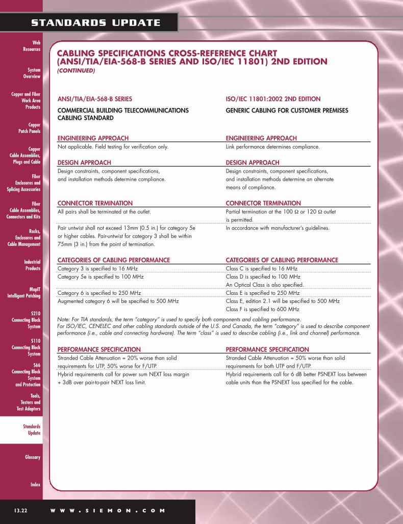
System Overview
Racks, Enclosures and
Cable Management
MapITIntelligent Patching
S110Connecting Block
System
Tools, Testers and
Test Adapters
Glossary
Index
Industrial Products
S210Connecting Block
System
S66 Connecting Block
Systemand Protection
Web Resources
Copper and FiberWork Area
Products
Copper Patch Panels
Copper Cable Assemblies,
Plugs and Cable
13.22 W W W . S I E M O N . C O M
STANDARDS UPDATE
Fiber Enclosures and
Splicing Accessories
Fiber Cable Assemblies,
Connectors and Kits
Standards Update
ANSI/TIA/EIA-568-B SERIES
COMMERCIAL BUILDING TELECOMMUNICATIONS CABLING STANDARD
ENGINEERING APPROACHNot applicable. Field testing for verification only.
DESIGN APPROACHDesign constraints, component specifications, and installation methods determine compliance.
CONNECTOR TERMINATIONAll pairs shall be terminated at the outlet.
Pair untwist shall not exceed 13mm (0.5 in.) for category 5e or higher cables. Pair-untwist for category 3 shall be within75mm (3 in.) from the point of termination.
CATEGORIES OF CABLING PERFORMANCECategory 3 is specified to 16 MHzCategory 5e is specified to 100 MHz
Category 6 is specified to 250 MHz Augmented category 6 will be specified to 500 MHz
PERFORMANCE SPECIFICATIONStranded Cable Attenuation = 20% worse than solid requirements for UTP, 50% worse for F/UTP.Hybrid requirements call for power sum NEXT loss margin + 3dB over pair-to-pair NEXT loss limit.
ISO/IEC 11801:2002 2ND EDITION
GENERIC CABLING FOR CUSTOMER PREMISES
ENGINEERING APPROACHLink performance determines compliance.
DESIGN APPROACHDesign constraints, component specifications, and installation methods determine an alternatemeans of compliance.
CONNECTOR TERMINATIONPartial termination at the 100 Ω or 120 Ω outlet is permitted.In accordance with manufacturer’s guidelines.
CATEGORIES OF CABLING PERFORMANCEClass C is specified to 16 MHzClass D is specified to 100 MHzAn Optical Class is also specified.Class E is specified to 250 MHzClass E, edition 2.1 will be specified to 500 MHzClass F is specified to 600 MHz
PERFORMANCE SPECIFICATION Stranded Cable Attenuation = 50% worse than solid requirements for both UTP and F/UTP. Hybrid requirements call for 6 dB better PSNEXT loss betweencable units than the PSNEXT loss specified for the cable.
Note: For TIA standards, the term “category” is used to specify both components and cabling performance. For ISO/IEC, CENELEC and other cabling standards outside of the U.S. and Canada, the term “category” is used to describe componentperformance (i.e., cable and connecting hardware). The term “class” is used to describe cabling (i.e., link and channel) performance.
CABLING SPECIFICATIONS CROSS-REFERENCE CHART (ANSI/TIA/EIA-568-B SERIES AND ISO/IEC 11801) 2ND EDITION (CONTINUED)

System Overview
Racks, Enclosures and Cable Management
MapITIntelligent Patching
S110Connecting BlockSystem
Tools, Testers and Test Adapters
Glossary
Index
Industrial Products
Web Resources
W W W . S I E M O N . C O M 13.23
STANDARDS UPDATE
S210Connecting BlockSystem
S66 Connecting BlockSystemand Protection
Copper and FiberWork Area Products
Copper Patch Panels
Copper Cable Assemblies, Plugs and Cable
Fiber Enclosures andSplicing Accessories
Fiber Cable Assemblies,Connectors and Kits
Standards Update
HORIZONTAL TWISTED-PAIR CABLE
TWISTED-PAIR PATCH CORDS AND CROSS-CONNECT JUMPERS• Patch cords should use stranded cable
for adequate flex-life.• Stranded cables must meet the minimum
performance requirements for horizontalcable except that 20 percent more attenuation for UTP is allowed by ’568-B.2 and 50 percent more attenuation isallowed by ’11801:2002 for UTP andF/UTP.
• Color-code for cross-connect jumpers:One conductor white, the other a visiblydistinct color such as red or blue.
• Performance markings should beprovided to show the applicabletransmission category in addition tosafety markings.
• Insulated O.D. of stranded wires shouldbe 0.8mm (0.032 in.) to 1mm (0.039 in.) to fit into a modular plug.
• Production performance specificationsfor plug cord assemblies are addressedin ’568-B.2.
• Color Codes for Stranded, 100 Ω Patch Cord:
COLOR-CODING (SPECIFIED BY REFERENCE TO ICEA)
• Solid 4-pair 0.51mm (24 AWG) specified[0.64mm (22 AWG) solid also allowed]. An overall shield is optional.
• Performance marking should be provided toshow the applicable performance category.These markings do not replace safety markings.
• Color-coding:white/blue – bluewhite/orange – orangewhite/green – greenwhite/brown – brown
MULTI-PAIR CABLE• Performance markings should be provided to show the applicable
performance category. These markings do not replace safetymarkings.
• Services with incompatible signal levels should be partitioned into separate binder groups. Guidelines for shared sheaths are provided in Annex B of ’568-B.1.
• Transmission requirements are equivalent to horizontal cables exceptthat hybrid requirements apply when multiple cable units arecontained within the same sheath.
• Note: Tip conductors have colored insulation that corresponds to that of the binder group. Ring conductors have colored insulation that corresponds to that of the pair.
• Backbone twisted-pair cables consist of solid 0.51mm (24 AWG)cables that contain more than four pairs (typically multiples of 25-pairsare used). An overall shield is optional.
• Color-coding (specified by reference to ICEA: see chart to right).
Note: Because of their identical pair groupings, patch cords terminated with either T568A or T568B pair assignments may be used interchangeably, provided that both ends are terminated with the same pin/pair scheme.
OPTION 1 OPTION 2
white/blue – blue pair 1 green – redwhite/orange – orange pair 2 black – yellowwhite/green – green pair 3 blue – orangewhite/brown – brown pair 4 brown – slate

System Overview
Racks, Enclosures and
Cable Management
MapITIntelligent Patching
S110Connecting Block
System
Tools, Testers and
Test Adapters
Glossary
Index
Industrial Products
S210Connecting Block
System
S66 Connecting Block
Systemand Protection
Web Resources
Copper and FiberWork Area
Products
Copper Patch Panels
Copper Cable Assemblies,
Plugs and Cable
13.24 W W W . S I E M O N . C O M
STANDARDS UPDATE
Fiber Enclosures and
Splicing Accessories
Fiber Cable Assemblies,
Connectors and Kits
Standards Update
MODULAR WIRING REFERENCEMODULAR JACK STYLES:
There are four basic modular jack styles. The 8-position modular outlets are commonly and incorrectly referred to as “RJ45”. The6-position modular jack is commonly referred to as an RJ11. Using these terms can sometimes lead to confusion since the RJdesignations actually refer to very specific wiring configurations called Universal Service Order Code (USOC). The designation‘RJ’ means Registered Jack. Each of these basic jack styles can be wired for different RJ configurations. For example, the 6-positionjack can be wired as an RJ11C (1-pair), RJ14C (2-pair), or RJ25C (3-pair) configuration. An 8-position jack can be wired forconfigurations such as RJ61C (4-pair) and RJ48C. The keyed 8-position jack can be wired for RJ45S, RJ46S, and RJ47S.
MODULAR PLUG PAIR CONFIGURATIONSIt is important that the pairing of wires in the modular plug match the pairs in the modular jack as well as the horizontal andbackbone wiring. If they do not, the data being transmitted may be paired with incompatible signals. Modular cords wired tothe T568A color scheme on both ends are compatible with T568B systems and vice versa.
STRAIGHT-THROUGH OR REVERSED?Modular cords are used for two basic applications. One application uses them for patching between modular patch panels.When used in this manner modular cords should always be wired “straight-through” (pin 1 to pin 1, pin 2 to pin 2, pin 3 topin 3, etc.). The second major application uses modular cords to connect the workstation equipment (PC, phone, FAX, etc.) tothe modular outlet. These modular cords may either be wired “straight-through” or “reversed” (pin 1 to pin 6, pin 2 to pin 5,pin 3 to pin 4, etc.) depending on the system manufacturer’s specifications. This “reversed” wiring is typically used for voicesystems. The following is a guide to determine what type of modular cord you have.
white/blue – bluewhite/orange – orangewhite/green – greenwhite/brown – brown
8-position 8-position 6-positionT568A/T568B USOC USOCUTP Horizontal Cable (solid 24 AWG)
Note: The Siemon Company has developed a guide to modular hardware pin/pair assignments. Visit our website for a free copy.
8-position class F 8-position 8-position keyed 6-position
HOW TO READ A MODULAR CORDAlign the plugs side-by-side with the contacts facing you andcompare the wire colors from left to right. If the colors appear inthe same order on both plugs, the cord is wired “straight-through”. If the colors appear reversed on the second plug (fromright to left), the cord is wired “reversed”.

System Overview
Racks, Enclosures and Cable Management
MapITIntelligent Patching
S110Connecting BlockSystem
Tools, Testers and Test Adapters
Glossary
Index
Industrial Products
Web Resources
W W W . S I E M O N . C O M 13.25
STANDARDS UPDATE
S210Connecting BlockSystem
S66 Connecting BlockSystemand Protection
Copper and FiberWork Area Products
Copper Patch Panels
Copper Cable Assemblies, Plugs and Cable
Fiber Enclosures andSplicing Accessories
Fiber Cable Assemblies,Connectors and Kits
Standards Update
COMMON OUTLET CONFIGURATIONS
Two wiring schemes have been adopted by the ’568-B.1 and ’11801:2002standards. They are nearly identical exceptthat pairs two and three are reversed.T568A is the preferred scheme because it iscompatible with 1 or 2-pair USOC systems.Either configuration can be used forIntegrated Services Digital Network (ISDN)and high speed data applications.Transmission categories 3, 5e, and 6 areonly applicable to this type of pairgrouping.
Pair PINID #
T1 5R1 4T2 3R2 6T3 1R3 2T4 7R4 8
Pair PINID #
T1 5R1 4T2 1R2 2T3 3R3 6T4 7R4 8
USOC wiring is available for 1-, 2-, 3-, or4-pair systems. Pair 1 occupies the centerconductors, pair 2 occupies the next twocontacts out, etc. One advantage to thisscheme is that a 6-position plug configuredwith 1, 2, or 3 pairs can be inserted intoan 8-position jack and still maintain paircontinuity. A note of warning though, pins 1 and 8 on the jack may become damagedfrom this practice. A disadvantage is thepoor transmission performance associatedwith this type of pair sequence. None ofthese pair schemes is cabling standard compliant.
Pair PINID #
T1 5R1 4T2 3R2 6T3 2R3 7T4 1R4 8
Pair PINID #
T1 4R1 3T2 2R2 5T3 1R3 6
10BASE-T and100BASE-TX wiringspecifies an 8-positionjack but uses only twopairs. These are pairstwo and three of T568Aand T568B schemes.
Token Ring wiring useseither an 8-position or 6-position jack. The 8-position format is compatible with T568A,T568B, and USOCwiring schemes. The 6-position is compatiblewith 1- or 2-pair USOCwiring.
Pair PINID #
T1 1R1 2T2 3R2 6
Pair PINID #
T1 5R1 4T2 3R2 6
ANSI X3T9.5 TP-PMDuses the two outer pairsof an 8-position jack.These positions are designated as pair 3 and pair 4 of the T568Awiring scheme. Thiswiring scheme is alsoused for ATM.
Pair PINID #
T1 1R1 2T2 7R2 8
1000BASE-T and10GBASE-T wiringspecifies an 8-positionjack. Can be either theT568A or T568Bconfiguration. (See above)

System Overview
Racks, Enclosures and
Cable Management
MapITIntelligent Patching
S110Connecting Block
System
Tools, Testers and
Test Adapters
Glossary
Index
Industrial Products
S210Connecting Block
System
S66 Connecting Block
Systemand Protection
Web Resources
Copper and FiberWork Area
Products
Copper Patch Panels
Copper Cable Assemblies,
Plugs and Cable
13.26 W W W . S I E M O N . C O M
STANDARDS UPDATE
Fiber Enclosures and
Splicing Accessories
Fiber Cable Assemblies,
Connectors and Kits
Standards Update
RECOMMENDED CABLING PRACTICES
TWISTED-PAIR CONNECTOR TERMINATIONS• Pair twists shall be maintained as close as possible to the point
of termination.• Untwisting shall not exceed 75mm (3.0 in) for category 3 links
and 13mm (0.5 in) for category 5e and higher links.
• Connecting hardware shall be installed to provide well-organized installation with cable management and in accordance with manufacturer’s guidelines.
• Strip back only as much jacket as is required to terminate individual pairs.
RECOMMENDED COLOR-CODING SCHEMESIEMON COLOR # COLOR CODE
02. . . . . . . . white . . . 1st Level Backbone (MC/IC or MC/TC Terminations)03 . . . . . . . . . red . . . Key Telephone Systems04 . . . . . . . . gray . . . Second Level Backbone (IC/TC Terminations)05 . . . . . . . yellow . . . Miscellaneous (Auxiliary, Security, Alarms, etc.)06 . . . . . . . . blue . . . Horizontal Cable Terminations (a.k.a. Station Cable)
SIEMON COLOR # COLOR CODE07 . . . . . . . green . . . Network Connections (customer side of demarc)08 . . . . . . . purple . . . Common Equipment (PBX, Host, LANs, Muxes)09 . . . . . . orange . . . Demarcation Point (Central Office Terminations)60 . . . . . . . brown . . . Interbuilding Backbone (Campus Cable Terminations)
TWISTED-PAIR CABLING INSTALLATION PRACTICES• To avoid stretching, pulling tension should not exceed
110N (25 lbƒ) for 4-pair cables.• Installed bend radii shall not exceed:
– 4 times the cable diameter for horizontal UTP cables under no load conditions.
– 8 times the cable diameter for horizontal ScTP cables.– 10 times the cable diameter for multi-pair backbone
twisted-pair cables under no load conditions.
• Horizontal cables should be used with connecting hardware and patch cords (or jumpers) of the same performance categoryor higher.
• Avoid cable stress, as caused by: – cable twist during pulling or installation – tension in suspended cable runs – tightly cinched cable ties or staples – tight bend radii
• Important Note: Installed twisted-pair cabling shall be classifiedby the least performing component in the link.
DO’S: Terminate each horizontal cable on a dedicatedtelecommunications outlet.
Locate the main cross-connect near the center of thebuilding to limit cable distances.
Maintain the twist of horizontal and backbone cablepairs up to the point of termination.
Tie and dress horizontal cables neatly and with aminimum bend radius of 4 times the cable diameter.
Use hook and loop tie wraps.
DON’TS: Do not use connecting hardware that is of a lowercategory than the cable being used.
Do not create multiple appearances of the same cable at several distribution points (called bridged taps).
Do not over-tighten cable ties, use staples, or makesharp bends with cables.
Do not place cable near equipment that may generate high levels of electromagnetic interference.
APPLICATION-SPECIFIC PAIR ASSIGNMENTS FOR THE 100 OHM CABLINGAPPLICATION PINS 1-2 PINS 3-6 PINS 4-5 PINS 7-8ISDN . . . . . . . . . . . . . . . . Power . . . . . . . . . . . TX . . . . . . . . . . . . RX . . . . . . . . . . . PowerAnalog Voice. . . . . . . . . . . . —. . . . . . . . . . . . . — . . . . . . . . . . . TX/RX . . . . . . . . . . . —802-3 (10BASE-T) . . . . . . . . TX . . . . . . . . . . . . RX . . . . . . . . . . . . —. . . . . . . . . . . . . —802-5 (Token Ring) . . . . . . . . —. . . . . . . . . . . . . TX . . . . . . . . . . . . RX . . . . . . . . . . . . —FDDI (TP-PMD) . . . . . . . . . . . TX . . . . . . . . . . Optional1 . . . . . . . . Optional1 . . . . . . . . . . RXATM User Device . . . . . . . . . TX . . . . . . . . . . Optional1 . . . . . . . . Optional1 . . . . . . . . . . RXATM Network Equip. . . . . . . RX . . . . . . . . . . Optional1 . . . . . . . . Optional1 . . . . . . . . . . TX10GBASE-T (802.3an) . . . . . Bi . . . . . . . . . . . . . Bi . . . . . . . . . . . . . Bi . . . . . . . . . . . . . Bi1000BASE-T (802.3ab) . . . . . Bi . . . . . . . . . . . . . Bi . . . . . . . . . . . . . Bi . . . . . . . . . . . . . Bi1000BASE-TX (TIA/EIA 854) . TX . . . . . . . . . . . . RX . . . . . . . . . . . . TX . . . . . . . . . . . . RX100BASE-VG (802.12) . . . . . Bi . . . . . . . . . . . . . Bi . . . . . . . . . . . . . Bi . . . . . . . . . . . . . Bi100BASE-T4 (802.3u). . . . . . TX . . . . . . . . . . . . RX. . . . . . . . . . . . . Bi . . . . . . . . . . . . . Bi100BASE-TX (802.3u). . . . . . TX . . . . . . . . . . . . RX . . . . . . . . . . . . —. . . . . . . . . . . . . —1000BASE-TX2/4 . . . . . . . . TX . . . . . . . . . . . . RX . . . . . . . . . . . . —. . . . . . . . . . . . . —
*Bi = bi-directional TX = TransmitRX = Receive
1Optional terminationsmay be required bysome manufacturers’active implementations.
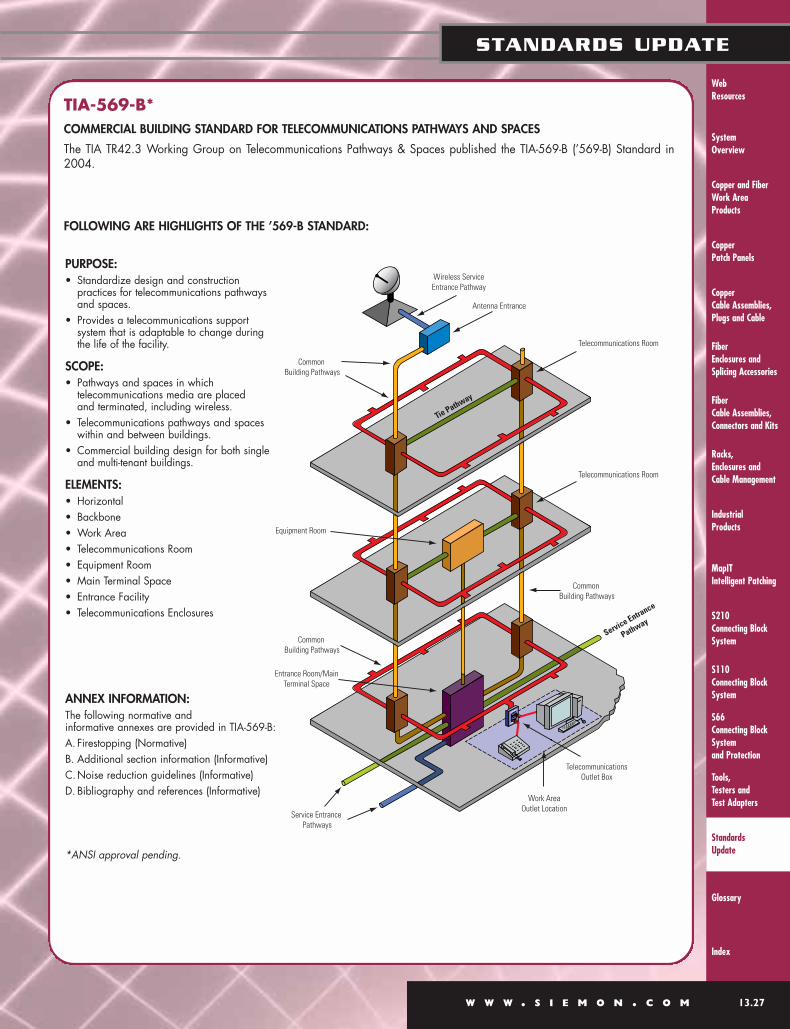
System Overview
Racks, Enclosures and Cable Management
MapITIntelligent Patching
S110Connecting BlockSystem
Tools, Testers and Test Adapters
Glossary
Index
Industrial Products
Web Resources
W W W . S I E M O N . C O M 13.27
STANDARDS UPDATE
S210Connecting BlockSystem
S66 Connecting BlockSystemand Protection
Copper and FiberWork Area Products
Copper Patch Panels
Copper Cable Assemblies, Plugs and Cable
Fiber Enclosures andSplicing Accessories
Fiber Cable Assemblies,Connectors and Kits
Standards Update
TIA-569-B*COMMERCIAL BUILDING STANDARD FOR TELECOMMUNICATIONS PATHWAYS AND SPACES
The TIA TR42.3 Working Group on Telecommunications Pathways & Spaces published the TIA-569-B (’569-B) Standard in2004.
FOLLOWING ARE HIGHLIGHTS OF THE ’569-B STANDARD:
PURPOSE:• Standardize design and construction
practices for telecommunications pathwaysand spaces.
• Provides a telecommunications support system that is adaptable to change during the life of the facility.
SCOPE:• Pathways and spaces in which
telecommunications media are placed and terminated, including wireless.
• Telecommunications pathways and spaceswithin and between buildings.
• Commercial building design for both singleand multi-tenant buildings.
ELEMENTS:• Horizontal• Backbone• Work Area• Telecommunications Room• Equipment Room• Main Terminal Space• Entrance Facility• Telecommunications Enclosures
ANNEX INFORMATION:The following normative and informative annexes are provided in TIA-569-B:A. Firestopping (Normative)B. Additional section information (Informative)C.Noise reduction guidelines (Informative)D. Bibliography and references (Informative)
*ANSI approval pending.
Common Building Pathways
Equipment Room
Common Building Pathways
Entrance Room/MainTerminal Space
Service Entrance Pathways
Work AreaOutlet Location
TelecommunicationsOutlet Box
Common Building Pathways
Telecommunications Room
Telecommunications Room
Antenna Entrance
Wireless ServiceEntrance Pathway
Service Entrance
Pathway
Tie Pathway
System Overview
Racks, Enclosures and
Cable Management
MapITIntelligent Patching
S110Connecting Block
System
Tools, Testers and
Test Adapters
Glossary
Index
Industrial Products
S210Connecting Block
System
S66 Connecting Block
Systemand Protection
Web Resources
Copper and FiberWork Area
Products
Copper Patch Panels
Copper Cable Assemblies,
Plugs and Cable
13.28 W W W . S I E M O N . C O M
STANDARDS UPDATE
Fiber Enclosures and
Splicing Accessories
Fiber Cable Assemblies,
Connectors and Kits
Standards Update
BUILDING AND BACKBONE INCLUDES:
PATHWAY TYPES:• CEILING — Open environment above accessible ceiling tiles
and frame work.
• ACCESS FLOOR — Raised modular floor tile supported bypedestals, with or without lateral bracing or stringers.
• TRAY & RUNWAY — Prefabricated rigid structures for pulling or placing cable.
• CONDUIT — Metallic and nonmetallic tubing of rigid or flexible construction permitted by applicable electrical code.
• FURNITURE — Modular systems of furniture containingpathways/raceways for concealing cable and terminatingoutlets.
• IN-FLOOR — Network of raceways embedded in concrete consisting of distribution and header ducts, trenches, and cellular systems.
• PERIMETER — Surface, recessed, molding, and multi-channel raceway systems for wall mounting around rooms or along hallways.
• VERTICAL PATHWAYS — Sleeve or conduit and slotpenetrations for access to other floors.
• UTILITY COLUMNS — Vertical channel for cable access to workarea locations.
• PARTITION CABLING — Where demountable partitions areused to conceal cables.
• IN-WALL CABLING — Where cables pass through studopenings.
SPACE TYPES:• ENTRANCE FACILITIES — Telecommunications service entrance
to the building including entrance through the wall.
• ACCESS PROVIDER/SERVICE PROVIDE — Spaces location oftransmission, reception and support equipment.
• MULTI-TENANT BUILDING SPACES — Includes commonEquipment Room and column Telecommunications Room.
• BUILDING SPACES —
• Outlet box/bracket/poke-thru• Multi-user telecommunications outlet assembly• Consolidation Point• Splice box/zone box• Telecommunications Enclosure• Telecommunications Room• Equipment Room• Entrance Room
DESIGN CONSIDERATIONS:• Grounded per code and ANSI-J-STD-607-A (’607-A)
• Designed to handle recognized media as specified inANSI/TIA/EIA-568-B series
• Not allowed in elevator shafts
• Accommodate seismic zone requirements
• Installed in dry locations
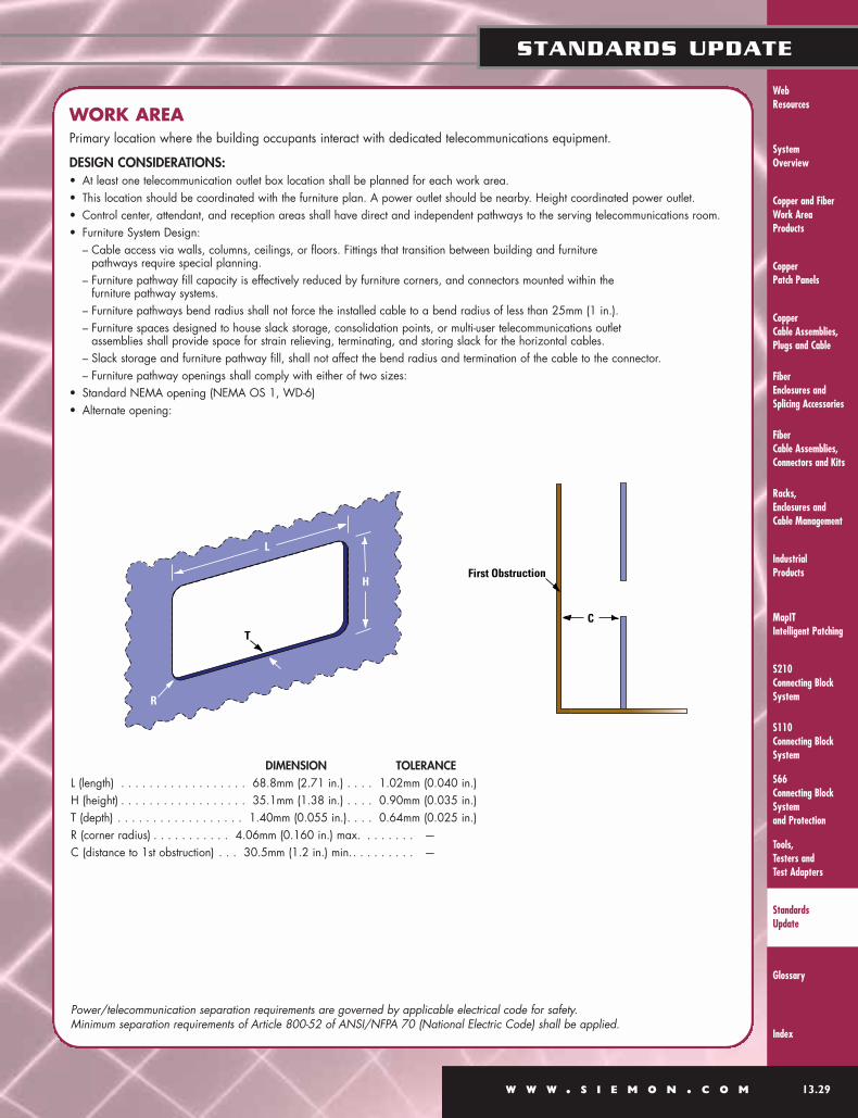
System Overview
Racks, Enclosures and Cable Management
MapITIntelligent Patching
S110Connecting BlockSystem
Tools, Testers and Test Adapters
Glossary
Index
Industrial Products
Web Resources
W W W . S I E M O N . C O M 13.29
STANDARDS UPDATE
S210Connecting BlockSystem
S66 Connecting BlockSystemand Protection
Copper and FiberWork Area Products
Copper Patch Panels
Copper Cable Assemblies, Plugs and Cable
Fiber Enclosures andSplicing Accessories
Fiber Cable Assemblies,Connectors and Kits
Standards Update
WORK AREAPrimary location where the building occupants interact with dedicated telecommunications equipment.
DESIGN CONSIDERATIONS:• At least one telecommunication outlet box location shall be planned for each work area.• This location should be coordinated with the furniture plan. A power outlet should be nearby. Height coordinated power outlet.• Control center, attendant, and reception areas shall have direct and independent pathways to the serving telecommunications room.• Furniture System Design:
– Cable access via walls, columns, ceilings, or floors. Fittings that transition between building and furniture pathways require special planning.
– Furniture pathway fill capacity is effectively reduced by furniture corners, and connectors mounted within the furniture pathway systems.
– Furniture pathways bend radius shall not force the installed cable to a bend radius of less than 25mm (1 in.).– Furniture spaces designed to house slack storage, consolidation points, or multi-user telecommunications outlet
assemblies shall provide space for strain relieving, terminating, and storing slack for the horizontal cables.– Slack storage and furniture pathway fill, shall not affect the bend radius and termination of the cable to the connector.– Furniture pathway openings shall comply with either of two sizes:
• Standard NEMA opening (NEMA OS 1, WD-6)• Alternate opening:
DIMENSION TOLERANCEL (length) . . . . . . . . . . . . . . . . . . 68.8mm (2.71 in.) . . . . 1.02mm (0.040 in.)H (height) . . . . . . . . . . . . . . . . . . 35.1mm (1.38 in.) . . . . 0.90mm (0.035 in.)T (depth) . . . . . . . . . . . . . . . . . . 1.40mm (0.055 in.). . . . 0.64mm (0.025 in.)R (corner radius) . . . . . . . . . . . 4.06mm (0.160 in.) max. . . . . . . . —C (distance to 1st obstruction) . . . 30.5mm (1.2 in.) min.. . . . . . . . . —
Power/telecommunication separation requirements are governed by applicable electrical code for safety. Minimum separation requirements of Article 800-52 of ANSI/NFPA 70 (National Electric Code) shall be applied.
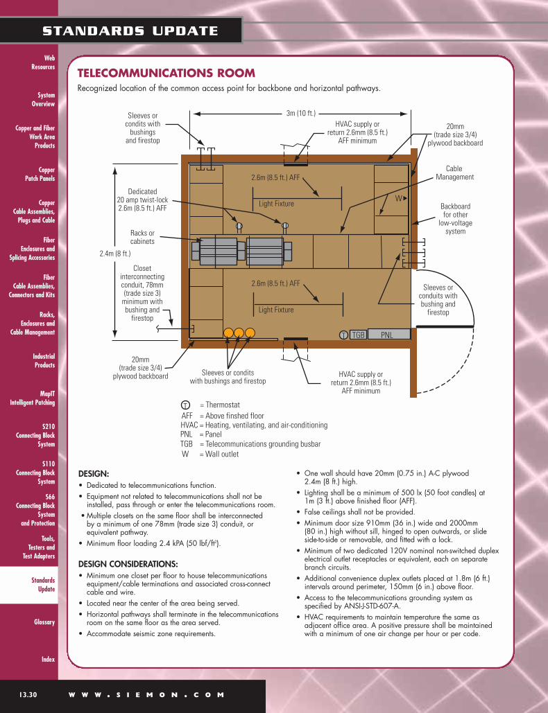
System Overview
Racks, Enclosures and
Cable Management
MapITIntelligent Patching
S110Connecting Block
System
Tools, Testers and
Test Adapters
Glossary
Index
Industrial Products
S210Connecting Block
System
S66 Connecting Block
Systemand Protection
Web Resources
Copper and FiberWork Area
Products
Copper Patch Panels
Copper Cable Assemblies,
Plugs and Cable
13.30 W W W . S I E M O N . C O M
STANDARDS UPDATE
Fiber Enclosures and
Splicing Accessories
Fiber Cable Assemblies,
Connectors and Kits
Standards Update
TELECOMMUNICATIONS ROOMRecognized location of the common access point for backbone and horizontal pathways.
DESIGN:• Dedicated to telecommunications function.• Equipment not related to telecommunications shall not be
installed, pass through or enter the telecommunications room.• Multiple closets on the same floor shall be interconnected
by a minimum of one 78mm (trade size 3) conduit, or equivalent pathway.
• Minimum floor loading 2.4 kPA (50 lbf/ft2).
DESIGN CONSIDERATIONS:• Minimum one closet per floor to house telecommunications
equipment/cable terminations and associated cross-connectcable and wire.
• Located near the center of the area being served.• Horizontal pathways shall terminate in the telecommunications
room on the same floor as the area served.• Accommodate seismic zone requirements.
• One wall should have 20mm (0.75 in.) A-C plywood 2.4m (8 ft.) high.
• Lighting shall be a minimum of 500 lx (50 foot candles) at 1m (3 ft.) above finished floor (AFF).
• False ceilings shall not be provided.• Minimum door size 910mm (36 in.) wide and 2000mm
(80 in.) high without sill, hinged to open outwards, or slideside-to-side or removable, and fitted with a lock.
• Minimum of two dedicated 120V nominal non-switched duplexelectrical outlet receptacles or equivalent, each on separatebranch circuits.
• Additional convenience duplex outlets placed at 1.8m (6 ft.)intervals around perimeter, 150mm (6 in.) above floor.
• Access to the telecommunications grounding system as specified by ANSI-J-STD-607-A.
• HVAC requirements to maintain temperature the same as adjacent office area. A positive pressure shall be maintainedwith a minimum of one air change per hour or per code.
Light Fixture
Light Fixture
20mm(trade size 3/4)
plywood backboard
Cable Management
Backboardfor other
low-voltagesystem
Sleeves orconduits withbushing and
firestop
HVAC supply orreturn 2.6mm (8.5 ft.)
AFF minimum
Sleeves or conditswith bushings and firestop
20mm(trade size 3/4)
plywood backboard
Closetinterconnectingconduit, 78mm(trade size 3)
minimum withbushing and
firestop
Dedicated20 amp twist-lock2.6m (8.5 ft.) AFF
Racks orcabinets
2.4m (8 ft.)
Sleeves orcondits with
bushingsand firestop
3m (10 ft.)
2.6m (8.5 ft.) AFF
2.6m (8.5 ft.) AFF
HVAC supply orreturn 2.6mm (8.5 ft.)
AFF minimum
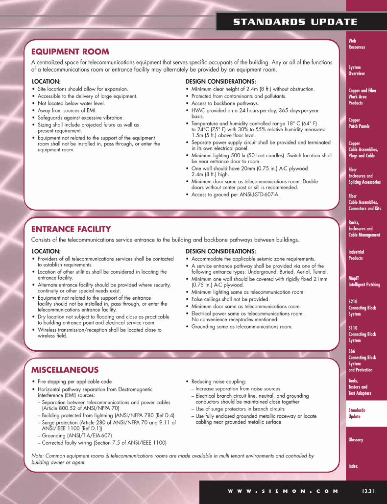
System Overview
Racks, Enclosures and Cable Management
MapITIntelligent Patching
S110Connecting BlockSystem
Tools, Testers and Test Adapters
Glossary
Index
Industrial Products
Web Resources
W W W . S I E M O N . C O M 13.31
STANDARDS UPDATE
S210Connecting BlockSystem
S66 Connecting BlockSystemand Protection
Copper and FiberWork Area Products
Copper Patch Panels
Copper Cable Assemblies, Plugs and Cable
Fiber Enclosures andSplicing Accessories
Fiber Cable Assemblies,Connectors and Kits
Standards Update
EQUIPMENT ROOMA centralized space for telecommunications equipment that serves specific occupants of the building. Any or all of the functionsof a telecommunications room or entrance facility may alternately be provided by an equipment room.
ENTRANCE FACILITYConsists of the telecommunications service entrance to the building and backbone pathways between buildings.
LOCATION:• Site locations should allow for expansion.• Accessible to the delivery of large equipment.• Not located below water level.• Away from sources of EMI.• Safeguards against excessive vibration.• Sizing shall include projected future as well as
present requirement.• Equipment not related to the support of the equipment
room shall not be installed in, pass through, or enter the equipment room.
DESIGN CONSIDERATIONS:• Minimum clear height of 2.4m (8 ft.) without obstruction.• Protected from contaminants and pollutants.• Access to backbone pathways.• HVAC provided on a 24 hours-per-day, 365 days-per-year
basis.• Temperature and humidity controlled range 18° C (64° F)
to 24°C (75° F) with 30% to 55% relative humidity measured1.5m (5 ft.) above floor level.
• Separate power supply circuit shall be provided and terminatedin its own electrical panel.
• Minimum lighting 500 lx (50 foot candles). Switch location shallbe near entrance door to room.
• One wall should have 20mm (0.75 in.) A-C plywood 2.4m (8 ft.) high.
• Minimum door same as telecommunications room. Doubledoors without center post or sill is recommended.
• Access to ground per ANSI-J-STD-607-A.
MISCELLANEOUS
LOCATION:• Providers of all telecommunications services shall be contacted
to establish requirements.• Location of other utilities shall be considered in locating the
entrance facility.• Alternate entrance facility should be provided where security,
continuity or other special needs exist.• Equipment not related to the support of the entrance
facility should not be installed in, pass through, or enter thetelecommunications entrance facility.
• Dry location not subject to flooding and close as practicable to building entrance point and electrical service room.
• Wireless transmission/reception shall be located close towireless field.
DESIGN CONSIDERATIONS:• Accommodate the applicable seismic zone requirements.• A service entrance pathway shall be provided via one of the
following entrance types: Underground, Buried, Aerial, Tunnel.• Minimum one wall should be covered with rigidly fixed 21mm
(0.75 in.) A-C plywood.• Minimum lighting same as telecommunication room.• False ceilings shall not be provided.• Minimum door same as telecommunications room.• Electrical power same as telecommunications room.
No convenience receptacles mentioned.• Grounding same as telecommunications room.
Note: Common equipment rooms & telecommunications rooms are made available in multi tenant environments and controlled bybuilding owner or agent.
• Fire stopping per applicable code• Horizontal pathway separation from Electromagnetic
interference (EMI) sources:– Separation between telecommunications and power cables
(Article 800.52 of ANSI/NFPA 70)– Building protected from lightning (ANSI/NFPA 780 (Ref D.4)– Surge protection (Article 280 of ANSI/NFPA 70 and 9.11 of
ANSI/IEEE 1100 [Ref D.1])– Grounding (ANSI/TIA/EIA-607)– Corrected faulty wiring (Section 7.5 of ANSI/IEEE 1100)
• Reducing noise coupling:– Increase separation from noise sources– Electrical branch circuit line, neutral, and grounding
conductors should be maintained close together– Use of surge protectors in branch circuits– Use fully enclosed grounded metallic raceway or locate
cabling near grounded metallic surface