
13 IN. THICKNESS PLANER - The Home Depot€¦ · · 2017-04-13Model # 6552 13 IN. THICKNESS...
18
Model # 6552 13 IN. THICKNESS PLANER bit.ly/wenvideo Your new tool has been engineered and manufactured to WEN’s highest standards for dependability, ease of operation, and operator safety. When properly cared for, this product will supply you years of rugged, trouble-free performance. Pay close attention to the rules for safe operation, warnings, and cautions. If you use your tool properly and for intended purpose, you will enjoy years of safe, reliable service. IMPORTANT: NEED HELP? CONTACT US! Have product questions? Need technical support? Please feel free to contact us at: 800-232-1195 [email protected] WENPRODUCTS.COM (M-F 8AM-5PM CST)
Transcript of 13 IN. THICKNESS PLANER - The Home Depot€¦ · · 2017-04-13Model # 6552 13 IN. THICKNESS...

Model # 6552
13 IN.THICKNESS PLANER
bit.ly/wenvideo
Your new tool has been engineered and manufactured to WEN’s highest standards for dependability, ease of operation, and operator safety. When properly cared for, this product will supply you years of rugged, trouble-free performance. Pay close attention to the rules for safe operation, warnings, and cautions. If you use your tool properly and for intended purpose, you will enjoy years of safe, reliable service.
IMPORTANT:
NEED HELP? CONTACT US!Have product questions? Need technical support?
Please feel free to contact us at:
WENPRODUCTS.COM
(M-F 8AM-5PM CST)
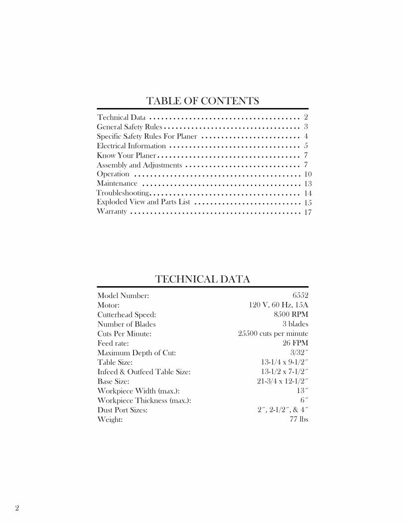
TABLE OF CONTENTS
Technical Data 2345771013141517
General Safety RulesSpecific Safety Rules For PlanerElectrical InformationKnow Your PlanerAssembly and AdjustmentsOperation
Exploded View and Parts ListWarranty
TECHNICAL DATA
Model Number:Motor:Cutterhead Speed:Number of BladesCuts Per Minute:Feed rate:Maximum Depth of Cut:Table Size:Infeed & Outfeed Table Size:Base Size:Workpiece Width (max.):Workpiece Thickness (max.):Dust Port Sizes:Weight:
6552120 V, 60 Hz, 15A
8500 RPM3 blades
25500 cuts per minute26 FPM
3/32˝13-1/4 x 9-1/2˝13-1/2 x 7-1/2˝
21-3/4 x 12-1/2˝13˝6˝
2˝, 2-1/2˝, & 4˝ 77 lbs
2
MaintenanceTroubleshooting
3
GENERAL SAFETY RULES
Safety is a combination of common sense, staying alert and knowing how your item works. SAVE THESE SAFE-TY INSTRUCTIONS.
WARNING: To avoid mistakes and serious injury, do not plug in your tool until the following steps have been read and understood.
1. READ and become familiar with this entire instruction manual. LEARN the tool’s applications, limitations, and possible hazards.
2. AVOID DANGEROUS CONDITIONS. Do not use power tools in wet or damp areas or expose them to rain. Keep work areas well lit.
3. DO NOT use power tools in the presence of flammable liquids or gases. 4. ALWAYS keep your work area clean, uncluttered, and well lit. DO NOT work on floor surfaces that are slippery with sawdust or wax.
5. KEEP BYSTANDERS AT A SAFE DISTANCE from the work area, especially when the tool is operating. NEVER allow children or pets near the tool.
6. DO NOT FORCE THE TOOL to do a job for which it was not designed.
7. DRESS FOR SAFETY. Do not wear loose clothing, gloves, neckties, or jewelry (rings, watches, etc.) when op-erating the tool. Inappropriate clothing and items can get caught in moving parts and draw you in. ALWAYS wear non-slip footwear and tie back long hair.
8. WEAR A FACE MASK OR DUST MASK to fight the dust produced by sawing operations.
WARNING: Dust generated from certain materials can be hazardous to your health. Always oper-ate the tool in a well-ventilated area and provide for proper dust removal. Use dust collection systems whenever possible.
9. ALWAYS remove the power cord plug from the electrical outlet when making adjustments, changing parts, cleaning, or working on the tool.
10. KEEP GUARDS IN PLACE AND IN WORKING ORDER.
11. AVOID ACCIDENTAL START-UPS. Make sure the power switch is in the OFF position before plugging in the power cord.
12. REMOVE ADJUSTMENT TOOLS. Always make sure all adjustment tools are removed from the saw before turning it on.
13. NEVER LEAVE A RUNNING TOOL UNATTENDED. Turn the power switch to OFF. Do not leave the tool until it has come to a complete stop.
14. NEVER STAND ON A TOOL. Serious injury could result if the tool tips or is accidentally hit. DO NOT store anything above or near the tool.
4
15. DO NOT OVERREACH. Keep proper footing and balance at all times. Wear oil-resistant rubber-soled foot-wear. Keep the floor clear of oil, scrap, and other debris.
16. MAINTAIN TOOLS PROPERLY. ALWAYS keep tools clean and in good working order. Follow instruc-tions for lubricating and changing accessories.
17. CHECK FOR DAMAGED PARTS. Check for alignment of moving parts, jamming, breakage, improper mounting, or any other conditions that may affect the tool’s operation. Any part that is damaged should be properly repaired or replaced before use.
18. MAKE THE WORKSHOP CHILDPROOF. Use padlocks and master switches and ALWAYS remove start-er keys.
19. DO NOT operate the tool if you are under the influence of drugs, alcohol, or medication that may affect your ability to properly use the tool.
20. USE SAFETY GOGGLES AT ALL TIMES that comply with ANSI Z87.1. Normal safety glasses only have impact resistant lenses and are not designed for safety. Wear a face or dust mask when working in a dusty environ-ment. Use ear protection such as plugs or muffs during extended periods of operation.
GENERAL SAFETY RULES
SPECIFIC RULES FOR THE PLANER
1. Whenever adjusting or replacing any parts on planer, turn switch OFF and remove plug from power source.
2. Make sure all guards are properly attached and securely fastened.
3. Make sure all moving parts are free from interference.
4. Always wear eye protection or face shield.
5. Make sure blades are aligned and properly attached to cutterhead.
6. Do not plug in planer unless the switch is in the off position. After turning the switch on, allow the planer to come to full speed before operating.
WARNING: For your own safety, read all of the instructions and precautions before operating tool.
WARNING: Operation of any power tool can result in foreign objects being thrown into eyes which can result in severe eye damage. Always wear safety goggles complying with United States ANSI Z87.1
(shown on package) before commencing power tool operation.
CAUTION: Always observe the following safety precautions:

5
SPECIFIC RULES FOR THE PLANER
ELECTRICAL INFORMATION
GROUNDING INSTRUCTIONS
IN THE EVENT OF A MALFUNCTION OR BREAKDOWN, grounding provides the path of least resistance for an electric current and reduces the risk of electric shock. This tool is equipped with an electric cord that has an equipment grounding conductor and a grounding plug. The plug MUST be plugged into a matching outlet that is properly installed and grounded in accordance with ALL local codes and ordinances.
DO NOT MODIFY THE PLUG PROVIDED. If it will not fit the outlet, have the proper outlet installed by a licensed electrician.
IMPROPER CONNECTION of the equipment grounding conductor can result in electric shock. The conduc-tor with the green insulation (with or without yellow stripes) is the equipment grounding conductor. If repair or replacement of the electric cord or plug is necessary, DO NOT connect the equipment grounding conductor to a live terminal.
CHECK with a licensed electrician or service personnel if you do not completely understand the grounding instruc-tions or whether the tool is properly grounded.
CAUTION: In all cases, make certain the outlet in question is properly grounded. If you are not sure, have a li-censed electrician check the outlet.
7. Keep hands clear of all moving parts.
8. Do not force cut. Slowing or stalling will overheat motor. Allow automatic feed to function properly.
9. Use quality lumber. Blades last longer and cuts are smoother with good quality wood.
10. Do not plane material shorter than 15”, narrower than 3/4”, wider than 13” or thinner than 1/2”.
11. Never make planing cut deeper than 3/32".
12. For workpieces longer than 24", use material support stands.
13. Do not back the work towards the infeed side.
14. Take precautions against kickback. Do not permit anyone to stand or cross in line of cutterhead’s rotation. Kickback or thrown debris will travel in this direction.
15. Turn switch off and disconnect power whenever planer is not in use.
16. Replace knives as they become damaged or dull.
17. Keep planer maintained. Follow maintenance instructions.

6
WARNING: This tool is for indoor use only. Do not expose to rain or use in damp locations.Guidelines for using extension cords
Make sure your extension cord is in good condition. When using an extension cord, be sure to use one heavy enough to carry the current your product will draw. An undersized cord will cause a drop in line voltage resulting in loss of power and overheating. The table below shows the correct size to be used according to cord length and nameplate ampere rating. When in doubt, use a heavier cord. The smaller the gauge number, the heavier the cord.
Make sure your extension cord is properly wired and in good condition. Always replace a damaged extension cord or have it repaired by a qualified person before using it.
Protect your extension cords from sharp objects, excessive heat and damp/wet areas.
Use a separate electrical circuit for your tools. This circuit must not be less than a #12 wire and should be protected with a 15 A time-delayed fuse. Before connecting the motor to the power line, make sure the switch is in the OFF position and the electric current is rated the same as the current stamped on the motor nameplate. Running at a lower voltage will damage the motor.
WARNING: This tool must be grounded while in use to protect the operator from electric shock.
ELECTRICAL INFORMATION
AMPERAGEREQUIRED GAUGE FOR EXTENSION CORDS
25 ft. 50 ft. 100 ft. 150 ft.
15 A 14 gauge 12 gauge 10 gauge 8 gauge
Circuit Breaker
CIRCUIT BREAKER
The planer is equipped with a motor pro-tection device-circuit breaker. The breaker will automatically shut the planer off when excessive current is consumed. If the breaker is tripped, turn the planer off and reset the circuit by pressing the button.
CAUTION: Be sure to turn the planer off prior to resetting the circuit breaker to avoid unintentional start-up of the planer.
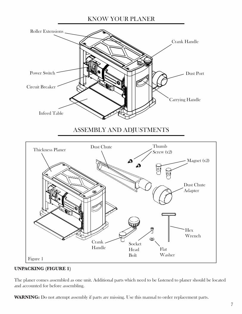
UNPACKING (FIGURE 1)
The planer comes assembled as one unit. Additional parts which need to be fastened to planer should be located and accounted for before assembling.
WARNING: Do not attempt assembly if parts are missing. Use this manual to order replacement parts.
7
KNOW YOUR PLANER
ASSEMBLY AND ADJUSTMENTS
Infeed Table
Circuit Breaker
Power Switch
Carrying Handle
Crank Handle
Figure 1
Dust Port
Roller Extensions
Thickness PlanerDust Chute Thumb
Screw (x2)
Magnet (x2)
Dust Chute Adapter
Crank Handle
Socket Head Bolt
Flat Washer
Hex Wrench
88
ASSEMBLY AND ADJUSTMENTS
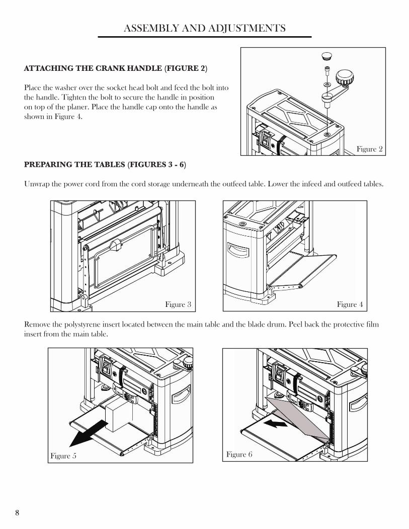
PREPARING THE TABLES (FIGURES 3 - 6)
Unwrap the power cord from the cord storage underneath the outfeed table. Lower the infeed and outfeed tables.
ATTACHING THE CRANK HANDLE (FIGURE 2)
Place the washer over the socket head bolt and feed the bolt into the handle. Tighten the bolt to secure the handle in position on top of the planer. Place the handle cap onto the handle as shown in Figure 4.
Figure 3 Figure 4
Remove the polystyrene insert located between the main table and the blade drum. Peel back the protective film insert from the main table.
Figure 2
Figure 5 Figure 6
9
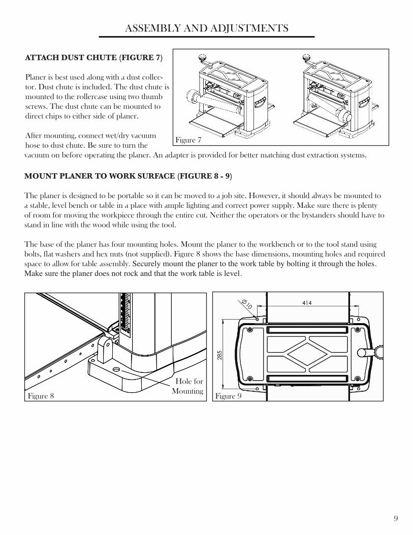
MOUNT PLANER TO WORK SURFACE (FIGURE 8 - 9)
The planer is designed to be portable so it can be moved to a job site. However, it should always be mounted to a stable, level bench or table in a place with ample lighting and correct power supply. Make sure there is plenty of room for moving the workpiece through the entire cut. Neither the operators or the bystanders should have to stand in line with the wood while using the tool.
The base of the planer has four mounting holes. Mount the planer to the workbench or to the tool stand using bolts, flat washers and hex nuts (not supplied). Figure 8 shows the base dimensions, mounting holes and required space to allow for table assembly. Securely mount the planer to the work table by bolting it through the holes. Make sure the planer does not rock and that the work table is level.
ATTACH DUST CHUTE (FIGURE 7)
Planer is best used along with a dust collec-tor. Dust chute is included. The dust chute is mounted to the rollercase using two thumb screws. The dust chute can be mounted to direct chips to either side of planer.
After mounting, connect wet/dry vacuum hose to dust chute. Be sure to turn the
ASSEMBLY AND ADJUSTMENTS
Figure 7
vacuum on before operating the planer. An adapter is provided for better matching dust extraction systems.
Figure 8 Figure 9
Hole for Mounting
10
OPERATION
The WEN 13-Inch Planer planes soft and hardwoods up to 6" thick and 13" wide. Wood feeds into the two-blade cutterhead by rubber infeed/outfeed rollers. Planer can take cuts up to 3/32" per pass at 26 feet per minute.
WARNING: Do not connect planer to the power source until all assembly steps have been completed.
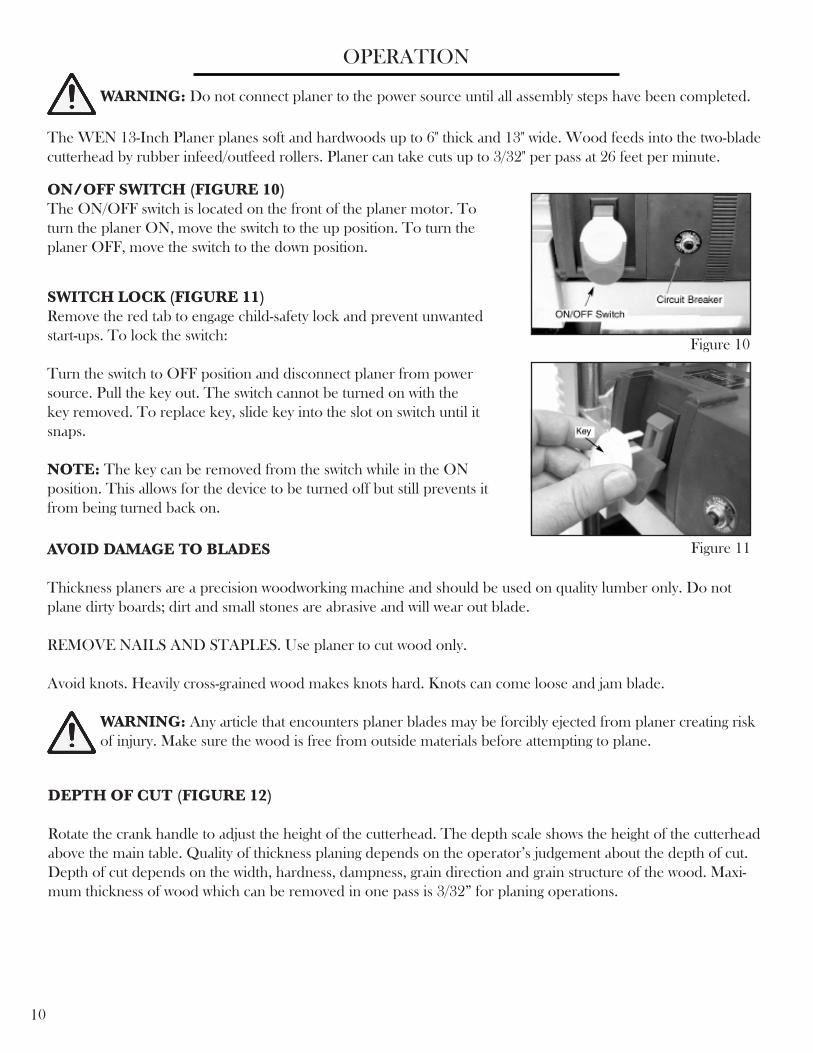
ON/OFF SWITCH (FIGURE 10)The ON/OFF switch is located on the front of the planer motor. To turn the planer ON, move the switch to the up position. To turn the planer OFF, move the switch to the down position.
SWITCH LOCK (FIGURE 11)Remove the red tab to engage child-safety lock and prevent unwanted start-ups. To lock the switch:
Turn the switch to OFF position and disconnect planer from power source. Pull the key out. The switch cannot be turned on with the key removed. To replace key, slide key into the slot on switch until it snaps.
NOTE: The key can be removed from the switch while in the ON position. This allows for the device to be turned off but still prevents it from being turned back on.
AVOID DAMAGE TO BLADES
Thickness planers are a precision woodworking machine and should be used on quality lumber only. Do not plane dirty boards; dirt and small stones are abrasive and will wear out blade.
REMOVE NAILS AND STAPLES. Use planer to cut wood only.
Avoid knots. Heavily cross-grained wood makes knots hard. Knots can come loose and jam blade.
WARNING: Any article that encounters planer blades may be forcibly ejected from planer creating risk of injury. Make sure the wood is free from outside materials before attempting to plane.
Figure 10
Figure 11
DEPTH OF CUT (FIGURE 12)
Rotate the crank handle to adjust the height of the cutterhead. The depth scale shows the height of the cutterhead above the main table. Quality of thickness planing depends on the operator’s judgement about the depth of cut. Depth of cut depends on the width, hardness, dampness, grain direction and grain structure of the wood. Maxi-mum thickness of wood which can be removed in one pass is 3/32” for planing operations.
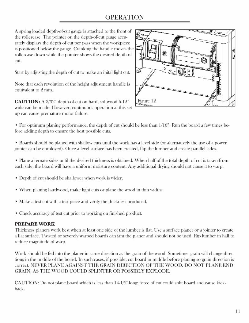
A spring loaded depth-of-cut gauge is attached to the front of the rollercase. The pointer on the depth-of-cut gauge accu-rately displays the depth of cut per pass when the workpiece is positioned below the gauge. Cranking the handle moves the rollercase down while the pointer shows the desired depth of cut.
Start by adjusting the depth of cut to make an inital light cut.
Note that each revolution of the height adjustment handle is equivalent to 2 mm.
CAUTION: A 3/32” depth-of-cut on hard, softwood 6-12” wide can be made. However, continuous operation at this set-up can cause premature motor failure.
• For optimum planing performance, the depth of cut should be less than 1/16”. Run the board a few times be-fore adding depth to ensure the best possible cuts.
• Boards should be planed with shallow cuts until the work has a level side (or alternatively the use of a power jointer can be employed). Once a level surface has been created, flip the lumber and create parallel sides.
• Plane alternate sides until the desired thickness is obtained. When half of the total depth of cut is taken from each side, the board will have a uniform moisture content. Any additional drying should not cause it to warp.
• Depth of cut should be shallower when work is wider.
• When planing hardwood, make light cuts or plane the wood in thin widths.
• Make a test cut with a test piece and verify the thickness produced.
• Check accuracy of test cut prior to working on finished product.
11
OPERATION
PREPARE WORKThickness planers work best when at least one side of the lumber is flat. Use a surface planer or a jointer to create a flat surface. Twisted or severely warped boards can jam the planer and should not be used. Rip lumber in half to reduce magnitude of warp.
Work should be fed into the planer in same direction as the grain of the wood. Sometimes grain will change direc-tions in the middle of the board. In such cases, if possible, cut board in middle before planing so grain direction is correct. NEVER PLANE AGAINST THE GRAIN DIRECTION OF THE WOOD. DO NOT PLANE END GRAIN, AS THE WOOD COULD SPLINTER OR POSSIBLY EXPLODE.
CAUTION: Do not plane board which is less than 14-1/2" long; force of cut could split board and cause kick-back.
Figure 12
12
OPERATION
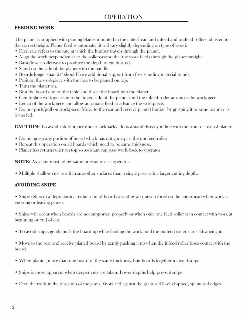
FEEDING WORK
The planer is supplied with planing blades mounted in the cutterhead and infeed and outfeed rollers adjusted to the correct height. Planer feed is automatic; it will vary slightly depending on type of wood.• Feed rate refers to the rate at which the lumber travels through the planer.• Align the work perpendicular to the rollercase so that the work feeds through the planer straight.• Raise/lower rollercase to produce the depth of cut desired.• Stand on the side of the planer with the handle.• Boards longer than 24" should have additional support from free standing material stands.• Position the workpiece with the face to be planed on top.• Turn the planer on.• Rest the board end on the table and direct the board into the planer.• Gently slide workpieces into the infeed side of the planer until the infeed roller advances the workpiece.• Let go of the workpiece and allow automatic feed to advance the workpiece.• Do not push/pull on workpiece. Move to the rear and receive planed lumber by grasping it in same manner as it was fed.
CAUTION: To avoid risk of injury due to kickbacks, do not stand directly in line with the front or rear of planer.
• Do not grasp any portion of board which has not gone past the out-feed roller.• Repeat this operation on all boards which need to be same thickness.• Planer has return roller on top so assistant can pass work back to operator.
NOTE: Assistant must follow same precautions as operator.
• Multiple shallow cuts result in smoother surfaces than a single pass with a larger cutting depth.
AVOIDING SNIPE
• Snipe refers to a depression at either end of board caused by an uneven force on the cutterhead when work is entering or leaving planer.
• Snipe will occur when boards are not supported properly or when only one feed roller is in contact with work at beginning or end of cut.
• To avoid snipe, gently push the board up while feeding the work until the outfeed roller starts advancing it.
• Move to the rear and receive planed board by gently pushing it up when the infeed roller loses contact with the board.
• When planing more than one board of the same thickness, butt boards together to avoid snipe.
• Snipe is more apparent when deeper cuts are taken. Lower depths help prevent snipe.
• Feed the work in the direction of the grain. Work fed against the grain will have chipped, splintered edges.
MAINTENANCE
13
CHECK FOR WORN BLADES
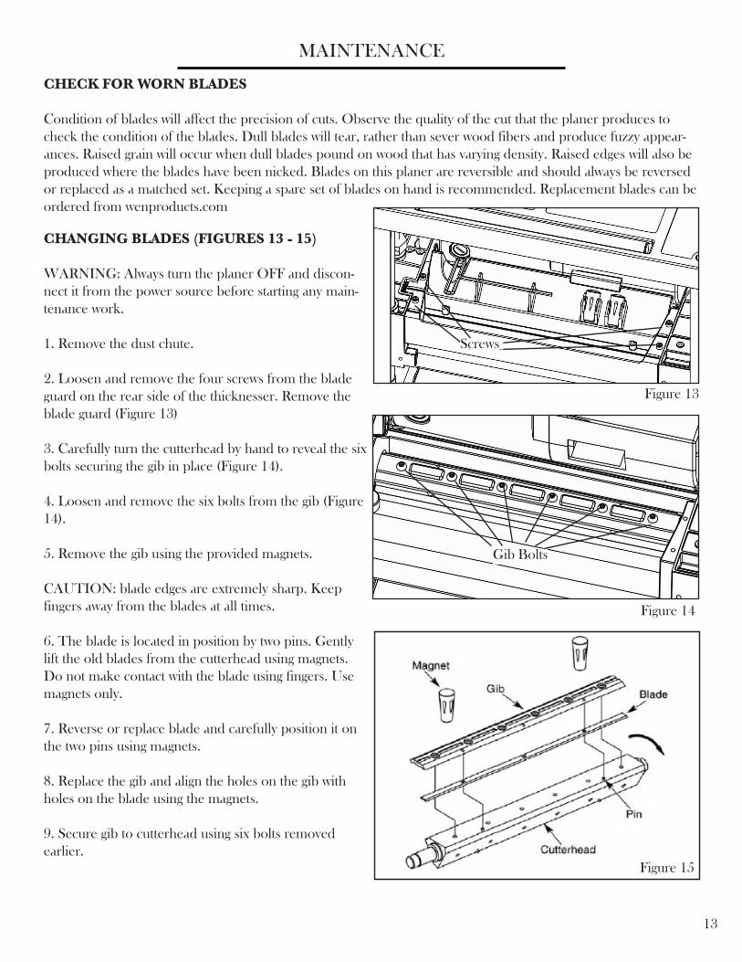
Condition of blades will affect the precision of cuts. Observe the quality of the cut that the planer produces to check the condition of the blades. Dull blades will tear, rather than sever wood fibers and produce fuzzy appear-ances. Raised grain will occur when dull blades pound on wood that has varying density. Raised edges will also be produced where the blades have been nicked. Blades on this planer are reversible and should always be reversed or replaced as a matched set. Keeping a spare set of blades on hand is recommended. Replacement blades can be ordered from wenproducts.com
CHANGING BLADES (FIGURES 13 - 15)
WARNING: Always turn the planer OFF and discon-nect it from the power source before starting any main-tenance work.
1. Remove the dust chute.
2. Loosen and remove the four screws from the blade guard on the rear side of the thicknesser. Remove the blade guard (Figure 13)
3. Carefully turn the cutterhead by hand to reveal the six bolts securing the gib in place (Figure 14).
4. Loosen and remove the six bolts from the gib (Figure 14).
5. Remove the gib using the provided magnets.
CAUTION: blade edges are extremely sharp. Keep fingers away from the blades at all times.
6. The blade is located in position by two pins. Gently lift the old blades from the cutterhead using magnets. Do not make contact with the blade using fingers. Use magnets only.
7. Reverse or replace blade and carefully position it on the two pins using magnets.
8. Replace the gib and align the holes on the gib with holes on the blade using the magnets.
9. Secure gib to cutterhead using six bolts removed earlier.
Figure 13
Figure 14
Figure 15
Screws
Gib Bolts
ADJUSTING TABLE LEVEL
Small screws appear underneath either side of both the infeed and outfeed tables, directly next to the hinge. These screws can be adjusted to make sure the tables are exactly level with the main working table. Small adjust-ments can be made, using a test piece of wood for test cuts.
LUBRICATIONMotor and cutterhead bearings are sealed and need no lubrication. Gears and elevation screws should be cleaned of debris and greased as needed.
CLEAN PLANERKeep planer clean of any wood chips, dust, dirt or debris. After 10 hours of operation, the chains and gears should have wood chips, dust and old grease removed. Use common automotive bearing grease to lubricate all chains and gears. Be sure all chains and gears have plenty of grease. Clean the granite table using a soft, damp cloth. Do not use any waxes, oils or solvents on the table.
IF THE MATERIAL DOES NOT FEED PROPERLY, CHECK FOR:• dull blades: rotate or replace as necessary (refer to Changing Blades section).• excess clogging in the dust hood (refer to Attach Dust Chute in the Assembly and Adjustments section).• a broken V-Belt (refer to Replacing V-Belt in the Maintenance section).
IF THE CIRCUIT BREAKER TRIPS REPEATEDLY:• Dull blades could be present. Dull blades can cause motor overloading. Rotate or replace as necessary (refer to Changing Blades section).
• Reduce the depth of cut. An overly aggressive cut could cause motor overloading (refer to Depth of Cut in the Operation section)
IF THE UNIT DOES NOT RUN, CHECK TO SEE:• if the unit is plugged in. Ensure unit is plugged into the appropriate outlet (refer to Electrical Information).• if the circuit breaker needs to be reset.• if the motor brushes are depleted. Replace as necessary (refer to Brush Inspection and Replacement under the Maintenance section).
TROUBLESHOOTING
14
MAINTENANCE
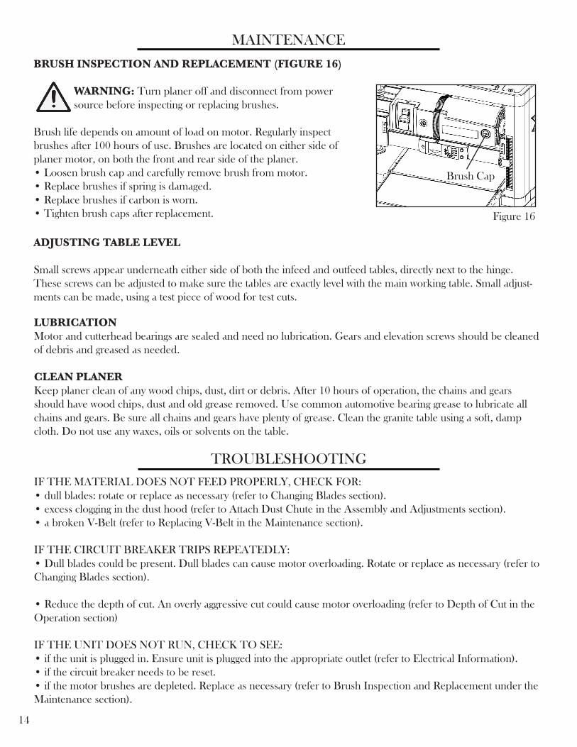
BRUSH INSPECTION AND REPLACEMENT (FIGURE 16)
WARNING: Turn planer off and disconnect from power source before inspecting or replacing brushes.
Brush life depends on amount of load on motor. Regularly inspect brushes after 100 hours of use. Brushes are located on either side of planer motor, on both the front and rear side of the planer.• Loosen brush cap and carefully remove brush from motor.• Replace brushes if spring is damaged.• Replace brushes if carbon is worn.• Tighten brush caps after replacement. Figure 16
Brush Cap

EXPLODED VIEW AND PARTS LIST

EXPLODED VIEW AND PARTS LIST
16
Part Number Description Quantity Part Number Description Quantity6552-001 Handle assembly 1 6552-061 Hex wrench 16552-002 Cap 1 6552-062 Magnet 26552-003 Socket head screw 1 6552-063 Spring 46552-004 Flat washer 1 6552-064 Bearing block 46552-005 Roller 2 6552-065 LH retainer 26552-006 Roller cap 4 6552-066 Flat washer 86552-007 Flat head screw 4 6552-067 Lock washer 86552-008 Top cover 1 6552-068 Socket head screw 86552-009 Grip 2 6552-069 Outfeed roller 16552-010 Flat head screw 4 6552-070 Rh retainer 26552-011 Left cover 2 6552-071 Infeed roller 16552-012 Retaining ring 3 6552-072 Power cord 16552-013 Chain 2 6552-073 Motor 16552-014 Sprocket 4 6552-074 Switch 16552-015 Socket head screw 4 6552-075 Circuit breaker 16552-016 Spacer 1 6552-076 Brush holder 26552-017 Gear box assembly 1 6552-077 Brush 26552-018 Pinion 1 6552-078 Brush cap 26552-019 Ball bearing 1 6552-079 Spacer 16552-020 Elevating nut (LH) 1 6552-080 Flat washer 16552-021 Hex nut 2 6552-081 Socket head screw 16552-022 Cable clamp 1 6552-082 Socket head screw 16552-023 Socket head screw 1 6552-083 Flat washer 16552-024 Chain cover 1 6552-084 Elevating screw (LH) 16552-025 Pan head screw 2 6552-085 Dust cover 26552-026 Lock washer 2 6552-086 Slide bearing 26552-027 Serrated washer 2 6552-087 Slide bearing housing 26552-028 Socket head screw 2 6552-088 Spacer 26552-029 Belt cover 1 6552-089 Flat washer 26552-030 Elevating nut (RH) 1 6552-090 Column 46552-031 Pan head screw 2 6552-091 Hex nut 46552-032 Pointer 1 6552-092 Guide 26552-033 Rollercase 1 6552-093 Table 16552-034 Motor pivot rod 1 6552-094 Socket head screw 86552-035 Rod clamp 2 6552-095 Flat washer 86552-036 Set screw 2 6552-096 Outfeed extension table 16552-037 Lock washer 4 6552-097 Flat washer 46552-038 Pan head screw 4 6552-098 Pan head screw 46552-039 Depth-of-cut gauge 1 6552-099 Hook 26552-040 Pan head screw 3 6552-100 Elevating screw (RH) 16552-041 Cutterhead 1 6552-101 Key 26552-042 Key 1 6552-102 Socket head screw 46552-043 Blade 3 6552-103 Lock washer 46552-044 Blade clamp 3 6552-104 Base 16552-045 Socket head screw 16 6552-105 Infeed extension table 16552-046 Ball bearing 1 6552-106 Bushing 46552-047 Bearing house 1 6552-107 Limiting plate A 26552-048 Pan head screw 3 6552-108 Flat washer 46552-049 Cutterhead pulley 1 6552-109 Lock washer 46552-050 Motor pulley 1 6552-110 Socket head screw 46552-051 Belt 1 6552-111 Limiting plate B 26552-052 Hex nut 1 6552-112 Hex head bolt 46552-053 Screw 2 6552-113 Hex nut 46552-054 Dust exhaust port 1 6552-114 Bevel gear 46552-055 Connecting port 1 6552-115 Nut 26552-056 Socket head screw 4 6552-116 Shaft 16552-057 Flat washer 4 6552-117 Key 26552-058 Dust chute 1 6552-118 Support 26552-059 Chute plate 1 6552-119 Socket head screw 46552-060 Flat head tap screw 4 6552-120 Retaining ring 2

17
WEN Products is committed to building tools that are dependable for years. Our warranties are consistent with this commitment and our dedication to quality.
LIMITED WARRANTY OF WEN CONSUMER POWER TOOLS PRODUCTS FOR HOME USE
GREAT LAKES TECHNOLOGIES, LLC (“Seller”) warrants to the original purchaser only, that all WEN con-sumer power tools will be free from defects in material or workmanship for a period of two (2) years from date of purchase. Ninety days for all WEN products, if the tool is used for professional use.
SELLER’S SOLE OBLIGATION AND YOUR EXCLUSIVE REMEDY under this Limited Warranty and, to the extent permitted by law, any warranty or condition implied by law, shall be the repair or replacement of parts, without charge, which are defective in material or workmanship and which have not been misused, carelessly handled, or misrepaired by persons other than Seller or Authorized Service Center. To make a claim under this Limited Warranty, you must make sure to keep a copy of your proof of purchase that clearly defines the Date of Purchase (month and year) and the Place of Purchase. Place of purchase must be a direct vendor of Great Lakes Technologies, LLC. Third party vendors such as garage sales, pawn shops, resale shops, or any other secondhand merchant void the warranty included with this product. Contact [email protected] or 1-800-232-1195 to make arrangements for repairs and transportation.
When returning a product for warranty service, the shipping charges must be prepaid by the purchaser. The prod-uct must be shipped in its original container (or an equivalent), properly packed to withstand the hazards of ship-ment. The product must be fully insured with a copy of the warranty card and/or the proof of purchase enclosed. There must also be a description of the problem in order to help our repairs department diagnose and fix the issue. Repairs will be made and the product will be returned and shipped back to the purchaser at no charge.
THIS LIMITED WARRANTY DOES NOT APPLY TO ACCESSORY ITEMS THAT WEAR OUT FROM REGULAR USAGE OVER TIME INCLUDING BELTS, BRUSHES, BLADES, ETC.
ANY IMPLIED WARRANTIES SHALL BE LIMITED IN DURATION TO TWO (2) YEARS FROM DATE OF PURCHASE. SOME STATES IN THE U.S., SOME CANADIAN PROVINCES DO NOT AL-LOW LIMITATIONS ON HOW LONG AN IMPLIED WARRANTY LASTS, SO THE ABOVE LIMITA-TION MAY NOT APPLY TO YOU.
IN NO EVENT SHALL SELLER BE LIABLE FOR ANY INCIDENTAL OR CONSEQUENTIAL DAM-AGES (INCLUDING BUT NOT LIMITED TO LIABILITY FOR LOSS OF PROFITS) ARISING FROM THE SALE OR USE OF THIS PRODUCT. SOME STATES IN THE U.S. AND SOME CANADIAN PROVINCES DO NOT ALLOW THE EXCLUSION OR LIMITATION OF INCIDENTAL OR CON-SEQUENTIAL DAMAGES, SO THE ABOVE LIMITATION OR EXCLUSION MAY NOT APPLY TO YOU.
THIS LIMITED WARRANTY GIVES YOU SPECIFIC LEGAL RIGHTS, AND YOU MAY ALSO HAVE OTHER RIGHTS WHICH VARY FROM STATE TO STATE IN THE U.S., PROVINCE TO PROVINCE IN CANADA AND FROM COUNTRY TO COUNTRY.THIS LIMITED WARRANTY APPLIES ONLY TO PORTABLE ELECTRIC TOOLS, BENCH POW-ER TOOLS, OUTDOOR POWER EQUIPMENT AND PNEUMATIC TOOLS SOLD WITHIN THE UNITED STATES OF AMERICA, CANADA AND THE COMMONWEALTH OF PUERTO RICO. FOR WARRANTY COVERAGE WITHIN OTHER COUNTRIES, CONTACT THE WEN CUSTOMER SUP-PORT LINE.
LIMITED TWO YEAR WARRANTY

18
THANKS FORREMEMBERING