124361534 daewoo-8140le-repair
-
Upload
victor-manuel-nunez -
Category
Automotive
-
view
548 -
download
7
Transcript of 124361534 daewoo-8140le-repair

[ RM-1 ]
DAEWOO 81-40LE (30510-81C008) 03/7 (DW-01M-MRM002)© All Rights Copyright AISIN AW CO., LTD.
FOREWORD
This REPAIR MANUAL covers Disassembly, Inspection and Assemblyprocedures for the following Automatic Transmission:
All information contained in this manual is the most up-to-date at the timeof publication. However, specifications and procedures are subject tochange without notice.
QUALITY ASSURANCE DEPT.
All rights reserved. This book may not bereproduced or copied, in whole or in part,without the written permission of AISIN AWCO., LTD.First Printing: Jul, 2003
© 2003
Automotic Transmission Engine Type REF No.
81-40LEDAEWOO: 96 484 421
AW: 30510-81C008
FAN I1.5L SOHC DW-01M-MRM002

[ RM-2 ]
DAEWOO 81-40LE (30510-81C008) 03/7 (DW-01M-MRM002)© All Rights Copyright AISIN AW CO., LTD.
ABBREVIATIONS
ASSY ............................................................ AssemblyA/T .......................................... Automatic TransmissionATF ................................ Automatic Transmission FluidB1 ........................................... O/D & 2nd Coast BrakeB2 .................................................................2nd BrakeB3 ................................................ 1st & Reverse BrakeC1 .........................................................Forward ClutchC2 ............................................................ Direct ClutchC3 ........................................................ Reverse ClutchF1.................................................... 1 Way Clutch No.1F2.................................................... 1 Way Clutch No.2O/D ............................................................. Over DriveV/B .............................................................. Valve BodyFIPG ...................................... Formed In Place GasketSST ...............................................Service Special ToolTT .................................................... Tightening TorqueT/M........................................................... TransmissionT/C .................................................... Torque ConverterFR .........................................................................FrontRR......................................................................... RearMID .................................................................... MiddleDIA ................................................................. DiameterB/G....................................................................Bearing

[ RM-3 ]
DAEWOO 81-40LE (30510-81C008) 03/7 (DW-01M-MRM002)© All Rights Copyright AISIN AW CO., LTD.
ABBREVIATIONS
SLT ........................ Throttle Pressure Control SolenoidS1,S2 .....................................Shift Solenoid No.1,No.2ST ....................................................... Timing SolenoidSL ................................................... Lock-Up SolenoidTh.................................................................. ThicknessL ......................................................................... LengthV........................................................................... ValveAcum......................................................... AccumulatorCont. ................................................................. ControlReg. .............................................................. RegulatorPress...............................................................PressureMod. .............................................................. ModulatorPla.................................................................. PlanetarySTD................................................................ StandardLUB. ...................................................................... LubeHSG ................................................................. HousingDiff ............................................................... Differential

[ RM-4 ]
DAEWOO 81-40LE (30510-81C008) 03/7 (DW-01M-MRM002)© All Rights Copyright AISIN AW CO., LTD.
BLANK

[ RM-5 ]
DAEWOO 81-40LE (30510-81C008) 03/7 (DW-01M-MRM002)© All Rights Copyright AISIN AW CO., LTD.
TABLE OF CONTENTS
FOREWORD ........................................................................................ RM-1ABBREVIATIONS ................................................................................ RM-2DESCRIPTION ..................................................................................... RM-6OPERATION ........................................................................................ RM-7REPAIR PROCEDURES...................................................................... RM-9GENERAL REPAIR INSTRUCTIONS................................................. RM-9REMOVAL OF COMPONENT PARTS............................................... RM-10ASSEMBLY AND DISASSEMBLY OF CONPONENTS .................... RM-321. OIL PUMP .......................................................................................................... RM-322. DIRECT CLUTCH (C2) ...................................................................................... RM-363. PLANETARY RING GEAR ................................................................................ RM-434. 1 WAY CLUTCH................................................................................................. RM-455. FORWARD AND REVERSE CLUTCH (C1,C3) ................................................. RM-486. COUNTER DRIVEN GEAR................................................................................ RM-567. VALVE BODY .................................................................................................... RM-598. DIFFERENTIAL ................................................................................................. RM-60INSTALLATION OF COMPONENT PARTS....................................... RM-61SERVICE SPECIFICATIONS ............................................................. RM-87

[ RM-6 ]
DAEWOO 81-40LE (30510-81C008) 03/7 (DW-01M-MRM002)© All Rights Copyright AISIN AW CO., LTD.
DESCRIPTION
The new automatic transmission AW 81-40LE is an electronically controlled4-speed automatic transmission with Lock-up mechanism.The transmission is mainly composed of the torque converter with lock upclutch, newly developed 4-speed planetary gear unit, the hydraulic controlsystem and the electric control system.
SECTIONAL VIEW
AW 81-40LE

[ RM-7 ]
DAEWOO 81-40LE (30510-81C008) 03/7 (DW-01M-MRM002)© All Rights Copyright AISIN AW CO., LTD.
OPERATION
��������� ������������������ ���������
��������� ���������������
�������������������������
��������������
��������������
��������
��������� ������������������ ���������
��������� �������
��������
�������������������������
��������������
��������������
��������
C 2B3B 2
B1
C 1
C 3
F1 F2
Differen tial Gear Assy
Counter Dr ive G ear Assy
C ounter Dr iven G ear Assy
FROM T /C

[ RM-8 ]
DAEWOO 81-40LE (30510-81C008) 03/7 (DW-01M-MRM002)© All Rights Copyright AISIN AW CO., LTD.
OPERATION
S1 S2 ST C1 C2 C3 B1 B2 B3 F1 F2ON ON OFF OFF OFF OFF OFF OFF OFF OFF OFF
V<9 ON ON OFF OFF OFF ON OFF OFF ON OFF OFFV>=11 ON ON ON OFF OFF OFF OFF OFF OFF OFF OFF
ON ON OFF OFF OFF OFF OFF OFF OFF OFF OFF1st ON ON OFF ON OFF OFF OFF OFF OFF OFF ON2nd ON OFF OFF ON OFF OFF OFF ON OFF ON OFF3rd OFF OFF OFF ON ON OFF OFF ON OFF OFF OFF
3<=>4 OFF ON ON ON<=>OFF ON OFF OFF<=>ON ON OFF OFF OFF4th OFF ON OFF OFF ON OFF ON ON OFF OFF OFF1st ON ON OFF ON OFF OFF OFF OFF OFF OFF ON2nd ON OFF OFF ON OFF OFF ON ON OFF ON OFF3rd OFF OFF OFF ON ON OFF OFF ON OFF OFF OFF1st ON ON OFF ON OFF OFF OFF OFF ON OFF ON2nd ON OFF OFF ON OFF OFF ON ON OFF ON OFF
D
2
L
Brake 1 Way Clutch
R
N
POSITION
P
Solenoid Clutch

[ RM-9 ]
DAEWOO 81-40LE (30510-81C008) 03/7 (DW-01M-MRM002)© All Rights Copyright AISIN AW CO., LTD.
REPAIR PROCEDURES
GENERAL REPAIR INSTRUCTIONS
1. Most repair operations begin with an overview illustration.2. It identifies the components and shows how the parts fit together.3. The procedures are presented in a step-by-step format:
(1) The illustration shows what to do and where to do it.(2) The task heading tells what to do.(3) The detailed text tells how to perform the task and gives other
information such as specifications and warnings.You never have to leave the procedure to look up your specs.
1. During disassembly, keep parts in order to facilitate reassembly.2.(1) Always replace gaskets, O-rings and oil seals etc. with new ones.
(2) Parts which cannot be reused are indicated by the symbol “ ”.3. When necessary, use a sealer on gaskets to prevent leaks.4. Carefully observe all specification for bolt tightening torque.
Always use a torque wrench.5. Use of SST may be required, depending on the nature of the repair.
Be sure to use SST where specified and follow the proper workprocedure.

[ RM-10 ] REMOVAL OF COMPONENT PARTS
DAEWOO 81-40LE (30510-81C008) 03/7 (DW-01M-MRM002)© All Rights Copyright AISIN AW CO., LTD.
REMOVAL OF COMPONENT PARTS
SS-01-81A
Breather Hose
Clip
No.1 Breather Plug
Bracket
Union
Transaxle RevolutionSensor
"O" Ring
"O" Ring
"O" Ring
Non Reusable Part
"O" Ring
Gasket
Speed Sensor
Union
Screw Plug

[ RM-11 ] REMOVAL OF COMPONENT PARTS
DAEWOO 81-40LE (30510-81C008) 03/7 (DW-01M-MRM002)© All Rights Copyright AISIN AW CO., LTD.
Gasket
Valve BodyAssembly
Gasket
Oil Seal
Torque Converter
Oil Seal
Newtral StartSwitch
Spacer
"O" ring
"O" ring
"O" ring
"O" ring
Brake DrumGasket
ApplyGasket
"O" ring
SS-01-01ANon Reusable Part

[ RM-12 ] REMOVAL OF COMPONENT PARTS
DAEWOO 81-40LE (30510-81C008) 03/7 (DW-01M-MRM002)© All Rights Copyright AISIN AW CO., LTD.
SS-01-02A
"O" Ring
"O" RingO/D BrakePiston
2nd BrakePiston
1st & ReverseBrake Piston
Forward Clutch Hub
Apply Gasket Transaxle RearCover
Forward Clutch & ReverseClutch Assembly
One-Way ClutchAssembly
Rear PlanetarySun Gear
Front PlanetarySun Gear
Planetary Gear
Planetary RingGear
"O" Ring
"O" Ring
Non Reusable Part

[ RM-13 ] REMOVAL OF COMPONENT PARTS
DAEWOO 81-40LE (30510-81C008) 03/7 (DW-01M-MRM002)© All Rights Copyright AISIN AW CO., LTD.
SS-01-03A
Oil SealDifferential Gear
Oil Pump
Counter Driven Gear
Counter DriveGear
Nut
Apply Gasket
Non Reusable Part
Direct ClutchAssembly
Direct Clutch Hub

[ RM-14 ] REMOVAL OF COMPONENT PARTS
DAEWOO 81-40LE (30510-81C008) 03/7 (DW-01M-MRM002)© All Rights Copyright AISIN AW CO., LTD.
3. REMOVE UNION(1) Remove the 2 unions.(2) Remove the 2 “O” rings from the unions.
4. REMOVE SCREW PLUG(1) Remove the screw plug from the transaxle
case.(2) Remove the “O” ring from the screw plug.
6. REMOVE INPUT SPEED SENSOR AND NO.1BREATHER PLUG
(1) Remove the 1 bolt and input speed sensor.(2) Remove the clip and breather hose.(3) Remove the No.1 breather plug.(4) Remove the “O” ring from the No.1 breather
plug.
5. REMOVE BRACKET(1) Remove the 1 bolt and bracket.
SEPARATE EXTERNAL PARTS1. REMOVE TORQUE CONVERTER2. REMOVE NEUTRAL START SWITCH(1) Remove the nut, washer and control lever.(2) Using a screwdriver, unstake the lock washer.(3) Remove the 2 bolts and nut, and pull out the
neutral start switch.
SS-01-04A
SS-01-05A
SS-01-06A
SS-01-80A
SS-01-07A

[ RM-15 ] REMOVAL OF COMPONENT PARTS
DAEWOO 81-40LE (30510-81C008) 03/7 (DW-01M-MRM002)© All Rights Copyright AISIN AW CO., LTD.
8. REMOVE OIL PAN AND GASKET(1) Remove the 18 bolts.(2) Remove the oil pan and gasket.(3) Remove the gasket and drain plug from the
oil pan.
9. EXAMINE PARTICLES IN PAN(1) Remove the magnets and use them to
collect any steel chips. Examine the chipsand particles in the pan and on the magnetto determine what type of wear has occurredin the transaxle:
Steel (magnetic)..... bearing, gear and plateware
Brass (non-magnetic)..... bushing wear10. REMOVE OIL STRAINER(1) Remove the 3 bolts and oil strainer.
(2) Remove the gasket from the oil strainer.
7. PLACE TRANSAXLE ON WOODENBLOCKS
SS-01-08A
SS-01-09A
SS-01-10A
SS-01-11A
SS-01-12A

[ RM-16 ] REMOVAL OF COMPONENT PARTS
DAEWOO 81-40LE (30510-81C008) 03/7 (DW-01M-MRM002)© All Rights Copyright AISIN AW CO., LTD.
(3) Support the valve body assembly andremove the 14 bolts.
(4) Disconnect the manual valve control rodfrom the manual valve lever, then removethe valve body assembly.
12. REMOVE CHECK VALVE(1) Remove the check valve and spring.
13. REMOVE BRAKE DRUM GASKET(1) Remove the brake drum gasket.
14. REMOVE APPLY GASKET
11. REMOVE VALVE BODY ASSEMBLY(1) Remove the bolt and ATF temperature
sensor with clamp.(2) Disconnect the 5 connectors.
SS-01-13A
SS-01-14A
SS-01-15A
SS-01-16A
SS-01-17A

[ RM-17 ] REMOVAL OF COMPONENT PARTS
DAEWOO 81-40LE (30510-81C008) 03/7 (DW-01M-MRM002)© All Rights Copyright AISIN AW CO., LTD.
(3) Remove the 2 “O” rings from the C2accumulator piston.
(6) Remove the 2 “O” rings from the C1accumulator piston.
(4) Apply compressed air (4.0 kgf/cm2) to the oilhole and remove the C1 accumulator pistonand spring.
(5) Remove the spring.CAUTION: Blowing off the air may cause the
piston's jump-out. When removingthe piston, hold it with your handusing a waste cloth. Take care notto splash ATF when air-blowing.
15. REMOVE ACCUMULATOR SPRING ANDPISTON
(1) Apply compressed air (4.0 kgf/cm2) to the oilhole and remove the C2 accumulator pistonand spring.
(2) Remove the spring.CAUTION: Blowing off the air may cause the
piston's jump-out. When removingthe piston, hold it with your handusing a waste cloth. Take care notto splash ATF when air-blowing.
SS-01-18A
SS-01-19A
SS-01-20A
SS-01-21A

[ RM-18 ] REMOVAL OF COMPONENT PARTS
DAEWOO 81-40LE (30510-81C008) 03/7 (DW-01M-MRM002)© All Rights Copyright AISIN AW CO., LTD.
16. REMOVE TRANSAXLE WIRE(1) Remove the 1 bolt.(2) Remove the transaxle wire from the
transaxle case.
(3) Remove the “O” ring from the transaxle wire.
(7) Apply compressed air (4.0 kgf/cm2) to theoil hole and remove the B1 accumulatorpiston and spring.
CAUTION: Blowing off the air may cause thepiston's jump-out. When removingthe piston, hold it with your handusing a waste cloth. Take care notto splash ATF when air-blowing.
(8) Remove the 2 “O” rings from the B1accumulator piston.
SS-01-22A
SS-01-23A
SS-01-24A
SS-01-25A

[ RM-19 ] REMOVAL OF COMPONENT PARTS
DAEWOO 81-40LE (30510-81C008) 03/7 (DW-01M-MRM002)© All Rights Copyright AISIN AW CO., LTD.
21. REMOVE DIFFERENTIAL GEARASSEMBLY
18. REMOVE TRANSAXLE HOUSING(1) Remove the 16 bolts.(2) Tap on the circumference of the transaxle
housing with a plastic hammer to remove thetransaxle housing from the transaxle case.
CAUTION: Differential gear assembly may beaccidentally removed when thetransaxle housing is removed.
19. INSPECT INPUT SHAFT END PLAY(1) Using a dial indicator, measure the input
shaft end play.
20. REMOVE OIL PUMP(1) Remove the 6 bolts and oil pump.
17. REMOVE VEHICLE SPEED SENSOR(1) Remove the 1 bolt and the vehicle speed
sensor.
SS-01-26A
SS-01-27A
SS-01-28A
SS-01-29A
SS-01-82A

[ RM-20 ] REMOVAL OF COMPONENT PARTS
DAEWOO 81-40LE (30510-81C008) 03/7 (DW-01M-MRM002)© All Rights Copyright AISIN AW CO., LTD.
25. REMOVE COUNTER DRIVEN GEARASSEMBLY
23. REMOVE DIRECT CLUTCH ASSEMBLY
(1) Remove the direct clutch assembly fromthe transaxle case.
(2) Remove the thrust needle roller bearingfrom the direct clutch assembly.
24. REMOVE DIRECT CLUTCH HUB(1) Remove the direct clutch hub, thrust needle
roller bearing and thrust bearing race fromthe transaxle case.
22. REMOVE APPLY GASKET
SS-01-30A
SS-01-31A
SS-01-32A
SS-01-33A
SS-01-34A

[ RM-21 ] REMOVAL OF COMPONENT PARTS
DAEWOO 81-40LE (30510-81C008) 03/7 (DW-01M-MRM002)© All Rights Copyright AISIN AW CO., LTD.
(2) Remove the thrust needle roller bearing andthrust bearing race from the forward &reverse clutch assembly.
26. REMOVE TRANSAXLE REAR COVER(1) Remove the 9 bolts.(2) Tap on the circumference of the transaxle
rear cover with a plastic hammer to removethe transaxle rear cover from the transaxlecase.
27. REMOVE 4 APPLY GASKETS
28. REMOVE 2ND COAST & O/D BRAKEFLANGE, DISC AND PLATE
(1) Remove the flange, 2 discs and 2 platesfrom the transaxle case.
29. REMOVE FORWARD & REVERSE CLUTCHASSEMBLY
(1) Remove the thrust needle roller bearing andforward & reverse clutch assembly.
SS-01-35A
SS-01-36A
SS-01-37A
SS-01-38A
SS-01-39A

[ RM-22 ] REMOVAL OF COMPONENT PARTS
DAEWOO 81-40LE (30510-81C008) 03/7 (DW-01M-MRM002)© All Rights Copyright AISIN AW CO., LTD.
(3) Remove the thrust needle roller bearing andplanetary carrier thrust washer from the rearplanetary sun gear and 1 way clutchassembly.
(2) Remove the thrust bearing race and thrustneedle roller bearing from the forward clutchhub.
31. REMOVE REAR PLANETARY SUN GEARAND 1 WAY CLUTCH ASSEMBLY
(1) Remove the rear planetary sun gear and 1way clutch assembly.
30. REMOVE FORWARD CLUTCH HUB(1) Remove the forward clutch hub from the
transaxle case.
SS-01-40A
SS-01-41A
SS-01-42A
SS-01-43A
SS-01-44A
(2) Remove the thrust bearing race from therear planetary sun gear and 1 way clutchassembly.

[ RM-23 ] REMOVAL OF COMPONENT PARTS
DAEWOO 81-40LE (30510-81C008) 03/7 (DW-01M-MRM002)© All Rights Copyright AISIN AW CO., LTD.
(3) Remove the 2 “O” rings from the 2nd brakepiston.
32. REMOVE FRONT PLANETARY SUN GEAR(1) Remove the front planetary sun gear from
the transaxle case.(2) Remove the thrust bearing race from the
front planetary sun gear.
33. REMOVE 2ND BRAKE(1) Using SST and a press, remove the 2 snap
rings, 2ND brake and 2ND brake pistonreturn spring.
CAUTION: Stop the press when the 2nd brakeis lowered 1 - 2 mm from the snapring groove, preventing the 2ndbrake from being deformed.
(2) Apply compressed air (4.0 kgf/cm2) to the2nd brake to remove the 2nd brake pistonfrom the 2nd brake clutch cylinder.
CAUTION: Blowing off the air may cause thepiston's jump-out. When removingthe piston, hold it with your handusing a waste cloth. Take care notto splash ATF when air-blowing.
(4) Remove the 1 way clutch assembly andthrust washer from the rear planetary sungear.
SS-01-45A
SS-01-46A
SS-01-47A
SS-01-48A
SS-01-83A
SST

[ RM-24 ] REMOVAL OF COMPONENT PARTS
DAEWOO 81-40LE (30510-81C008) 03/7 (DW-01M-MRM002)© All Rights Copyright AISIN AW CO., LTD.
(2) Remove the No.2 one-way clutch from theplanetary gear.
(3) Remove the anti-rattle clip.
35. REMOVE COUNTER DRIVE GEAR ANDPLANETARY RING GEAR
(1) Fix the counter drive gear with the parkinglock pawl.
34. REMOVE NO.2 1 WAY CLUTCH ANDPLANETARY GEAR
(1) Remove the No.2 1 way clutch and planetarygear from the transaxle case.
(4) Remove the 2 plates, 2 discs and flange.
SS-01-49A
SS-01-50A
SS-01-51A
SS-01-52A

[ RM-25 ] REMOVAL OF COMPONENT PARTS
DAEWOO 81-40LE (30510-81C008) 03/7 (DW-01M-MRM002)© All Rights Copyright AISIN AW CO., LTD.
(4) Remove the nut.CAUTION: Remove the nut without unstaking
the planetary ring gear. If chisel orother tool is used to unstake theplanetary ring gear, such impactmay damage the bearing.
(3) Using SST and a hammer, unstake thecounter drive gear nut.
SS-01-53A
SS-01-84A
SST
SST
SS-01-86C
(2) Using SST, lift the transaxle case.

[ RM-26 ] REMOVAL OF COMPONENT PARTS
DAEWOO 81-40LE (30510-81C008) 03/7 (DW-01M-MRM002)© All Rights Copyright AISIN AW CO., LTD.
SS-01-54A
SS-01-55A
(5) Install the 3 bolts to the counter drove gear.Bolt (M6):L = 40 - 80 mmPitch = 1.0 mm(6) Rotate 3 bolts in order and remove the
counter drive gear and planetary ring gear.
36. REMOVE PARKING LOCK PAWL(1) Remove the 2 bolts and parking lock pawl
bracket.
(2) Remove the parking lock pawl shaft, torsionspring and parking lock pawl.
SS-01-62A
SS-01-63C
SST

[ RM-27 ] REMOVAL OF COMPONENT PARTS
DAEWOO 81-40LE (30510-81C008) 03/7 (DW-01M-MRM002)© All Rights Copyright AISIN AW CO., LTD.
(5) Remove the parking lock rod from themanual valve lever.
(3) Using a pin punch and hammer, drive out thepin.
(4) Remove the manual valve lever shaft andmanual valve lever.
(2) Using a chisel and hammer, unstake andremove the spacer.
37. REMOVE MANUAL VALVE LEVER SHAFT(1) Remove the 1 bolt and manual detent spring.
SS-01-56A
SS-01-57A
SS-01-58A
SS-01-59A
SS-01-60A

[ RM-28 ] REMOVAL OF COMPONENT PARTS
DAEWOO 81-40LE (30510-81C008) 03/7 (DW-01M-MRM002)© All Rights Copyright AISIN AW CO., LTD.
(4) Remove the 2 “O” rings from the 1st &reverse brake piston.
38. REMOVE 1ST & REVERSE BRAKE(1) Using SST and a press, remove the snap
ring.
(2) Remove the flange, 4 plates, 4 discs andreturn spring.
(3) Apply compressed air (4.0 kgf/cm2) to thetransaxle case to remove the 1st & reversebrake piston.
CAUTION: Blowing off the air may cause thepiston's jump-out. When removingthee piston, hold it with your handusing a waste cloth. Take care notto splash ATF when air-blowing.
(6) Using a screwdriver, remove the oil seal.
SS-01-61A
SS-01-65A
SS-01-66A
SS-01-83A
SST
SS-01-64A

[ RM-29 ] REMOVAL OF COMPONENT PARTS
DAEWOO 81-40LE (30510-81C008) 03/7 (DW-01M-MRM002)© All Rights Copyright AISIN AW CO., LTD.
41. REMOVE OIL RESERVOIR LOCK PLATE(1) Remove the 3 bolts and oil reservoir lock
plate from the transxle housing.
42. REMOVE APPLY PIPE(1) Remove the 1 bolt and No.1 transaxle apply
pipe clamp from the transaxle housing.(2) Remove the transaxle lube apply pipe and
differential gear lube apply pipe from thetransaxle housing.
43. REMOVE OIL SEAL(1) Using SST and a hammer, remove the oil
seal from the transaxle housing.
40. REMOVE OUTER TAPERED ROLLERBEARING RACE AND SHIM FROMTRANSAXLE CASE
(1) Using SST, remove the outer tapered rollerbearing race and shim.
39. REMOVE NO.1 TRANSAXLE CASE PLATE(1) Remove the 1 bolt and No.1 transaxle case
plate from the transaxle case.
SS-01-67A
SS-01-70A
SS-01-71A
SST
SS-01-72A
SST
SS-01-68A

[ RM-30 ] REMOVAL OF COMPONENT PARTS
DAEWOO 81-40LE (30510-81C008) 03/7 (DW-01M-MRM002)© All Rights Copyright AISIN AW CO., LTD.
44. REMOVE OIL SEAL OF TRANSAXLEHOUSING
(1) Using SST and a hammer, remove the oilseal.
SS-01-73ASST
SS-01-75A
SS-01-85A
SST
(2) Remove the O/D brake return spring.
45. REMOVE O/D BRAKE PISTON(1) Using SST and a press, remove the snap
ring.CAUTION: Stop the press when the O/D
brake piston is lowered 1 - 2 mmfrom the snap ring grove,preventing the O/D brake pistonfrom being deformed.
SS-01-76A
SS-01-77A
(3) Apply compressed air (4.0 kgf/cm2) to thetransaxle rear cover to remove the O/Dbrake piston.
CAUTION: Blowing off the air may cause thepiston's jump-out. When removingthe piston, hold it with your handusing a waste cloth. Take care notto splash ATF when air-blowing.
(4) Remove the 2 “O” rings from the O/D brakepiston.

[ RM-31 ] REMOVAL OF COMPONENT PARTS
DAEWOO 81-40LE (30510-81C008) 03/7 (DW-01M-MRM002)© All Rights Copyright AISIN AW CO., LTD.
46. DISASSEMBLE TRANSAXLE REARCOVER
(1) Remove the 2 seal rings from the transaxlerear cover.
CAUTION: Do not expand the seal ringexcessively.
(2) Remove the 4 screw plugs and 4 “O” ringsfrom the transaxle rear cover.
SS-01-78A
SS-01-79A

[ RM-32 ] ASSEMBLY AND DISASSEMBLY OF COMPONENT PARTS
DAEWOO 81-40LE (30510-81C008) 03/7 (DW-01M-MRM002)© All Rights Copyright AISIN AW CO., LTD.
ASSEMBLY AND DISASSEMBLY OFCOMPONENT PARTS
1. OIL PUMP
SS-02-01A
Oil Pump Body
Oil Pump Drive Gear
Oil Pump Drive Gear
Stator Shaft

[ RM-33 ] ASSEMBLY AND DISASSEMBLY OF COMPONENT PARTS
DAEWOO 81-40LE (30510-81C008) 03/7 (DW-01M-MRM002)© All Rights Copyright AISIN AW CO., LTD.
DISASSEMBLY OF OIL PUMP1. CHECK OIL PUMP DRIVE GEAR ROTATION(1) Turn the drive gear with the 2 screwdrivers
and make sure it rotates smoothly.CAUTION: Be careful not to damage the oil lip.
2. REMOVE STATOR SHAFT(1) Remove the 8 bolts and stator shaft.CAUTION: Be careful not to let the drive gear
drop as it might come off attachedto the stator shaft.
3. REMOVE OIL PUMP DRiVE GEAR ANDDRIVEN GEAR
2. CHECK TIP CLEARANCE OF DRIVEN GEAR(1) Measure the tip clearance between the
driven gear teeth and drive gear teeth.
INSPECTION OF OIL PUMP1. CHECK BODY CLEARANCE OF DRIVEN
GEAR(1) Push the driven gear to one side of the body.
Using a feeler gauge, measure theclearance.
SS-02-02A
SS-02-03A
SS-02-04A
SS-02-05A
SS-02-06A
Body Clearance STD. 0.10-0.17 mmMAX 0.22 mm
Tip Clearance Driven STD. 0.07-0.15 mmMAX 0.20 mm

[ RM-34 ] ASSEMBLY AND DISASSEMBLY OF COMPONENT PARTS
DAEWOO 81-40LE (30510-81C008) 03/7 (DW-01M-MRM002)© All Rights Copyright AISIN AW CO., LTD.
3. CHECK SIDE CLEARANCE OF BOTH GEAR(1) Using a steel straight edge and feeler gauge,
measure the side clearance of both gears. Ifthe side clearance is greater the themaximum, select the drive and driven gear.
4. CHECK OIL PUMP BODY BUSHING(1) Using a dial indicator, measure the inside
diameter of the oil pump body bushing.
5. CHECK STATOR SHAFT BUSHING(1) Using a dial indicator, measure the inside
diameter of the stator shaft bushings.
SS-02-07A
SS-02-08A
SS-02-09A
Side Clearance of STD. 0.02-0.05 mmDrive and Driven Gear MAX 0.10 mm
Gear Thickness Mark Drive GearType 1 Th= 8.440-8.449 mm
2 Th= 8.450-8.459 mm3 Th= 8.460-8.470 mm4 Th= 8.471-8.480 mm5 Th= 8.481-8.490 mm
Mark Driven Gear1 Th= 8.440-8.449 mm2 Th= 8.450-8.459 mm3 Th= 8.460-8.470 mm4 Th= 8.471-8.480 mm5 Th= 8.481-8.490 mm
Body Bush STD. 38.113-38.138 mmMAX 38.188 mm
Stator Shaft Bush STD. 18.424-18.450 mmMAX 18.50 mm

[ RM-35 ] ASSEMBLY AND DISASSEMBLY OF COMPONENT PARTS
DAEWOO 81-40LE (30510-81C008) 03/7 (DW-01M-MRM002)© All Rights Copyright AISIN AW CO., LTD.
3. CHECK PUMP DRIVE GEAR ROTATION(1) Turn the drive gear with 2 screwdrivers and
make sure it rotates smoothly.CAUTION: Be careful not to damage the oil lip.
2. INSTALL STATOR SHAFT(1) Align the stator shaft with each bolt hole.(2) Install the 8 bolts.
TT = 7.8-11.8 N.m (80-120 kgf.cm)
ASSEMBLY OF OIL PUMP1. INSTALL OIL PUMP DRIVE GEAR AND
DRIVEN GEAR
SS-02-04A
SS-02-03A
SS-02-02A

[ RM-36 ] ASSEMBLY AND DISASSEMBLY OF COMPONENT PARTS
DAEWOO 81-40LE (30510-81C008) 03/7 (DW-01M-MRM002)© All Rights Copyright AISIN AW CO., LTD.
2. DIRECT CLUTCH
SS-03-01A
Seal Ring
Input ShaftSub-assembly
Return Spring
Snap Ring
"O" Ring
Non Reusable Part
"O" Ring
Piston
Snap Ring
Flange
Plate
Disc

[ RM-37 ] ASSEMBLY AND DISASSEMBLY OF COMPONENT PARTS
DAEWOO 81-40LE (30510-81C008) 03/7 (DW-01M-MRM002)© All Rights Copyright AISIN AW CO., LTD.
2. REMOVE SNAP RING(1) Using a screwdriver, remove the snap ring.
3. REMOVE FLANGE, DISC AND PLATE(1) Remove the flange, 2 discs and 2 plates.
DISASSEMBLY OF DIRECT CLUTCH1. CHECK PISTON STROKE OF DIRECT
CLUTCH(1) Install the direct clutch and thrust needle
roller bearing on the oil pump.(2) Using a dial indicator, measure the direct
clutch piston stroke while applying andreleasing compressed air (4.0 kgf/cm2).SS-03-02A
SS-03-03A
SS-03-04A
Piston Stroke 0.40-0.70 mm

[ RM-38 ] ASSEMBLY AND DISASSEMBLY OF COMPONENT PARTS
DAEWOO 81-40LE (30510-81C008) 03/7 (DW-01M-MRM002)© All Rights Copyright AISIN AW CO., LTD.
4. REMOVE DIRECT CLUTCH RETURNSPRING
(1) Place SST on the return spring andcompress.
(2) Using a snap ring expander, remove thesnap ring.
CAUTION: Stop the press when the pistonreturn spring is lowered to the place1-2 mm from the snap ring groove,preventing the piston return springfrom being deformed. Do notexpand the snap ring excessively.
(3) Remove the direct clutch return spring.
5. REMOVE DIRECT CLUTCH PISTON(1) Install the direct clutch on the oil pump.(2) Apply compressed air (4.0 kgf/cm2) to the oil
pump to remove the direct clutch piston.CAUTION: Blowing off the air may cause the
piston' jump-put. When removingthe piston, hold it with your handusing a waste cloth. Take care notto splash ATF when air-blowing.
HINT: When the piston cannot be removed as it isslanted, either blow the air again with theprotruding side pushed or remove thepiston using needle nose pliers with vinyltape on the tip.
SS-03-05A
SST
SS-03-06A
SS-03-07A

[ RM-39 ] ASSEMBLY AND DISASSEMBLY OF COMPONENT PARTS
DAEWOO 81-40LE (30510-81C008) 03/7 (DW-01M-MRM002)© All Rights Copyright AISIN AW CO., LTD.
6. REMOVE “O” RING(1) Using a small screwdriver, remove the “O”
ring from the direct clutch piston.
(2) Remove the “O” ring from the input shaft.
7. REMOVE SEAL RING(1) Remove the 2 seal rings from the input shaft.CAUTION: Do not expand the ring ends
excessively.
2. CHECK DIRECT CLUTCH RETURN SPRING(1) Using vernier calipers, measure the free
length of the spring together with the springsheet.
SS-03-09A
SS-03-10A
INSPECTION OF DIRECT CLUTCH1. INSPECT DISC AND FLANGE(1) Check to see if the sliding surface of the
disc, plate and flange are worm or burnt.HINT: If the lining of the disc is peeling off or
discolored, or even if a part of the printednumber is defaced, replace all discs.Before assembling new discs, soak them inATF for at least 15 minutes.
SS-03-11A
SS-03-12A
SS-03-08A
STD36.04 mm
Piston ReturnSpring Free Length

[ RM-40 ] ASSEMBLY AND DISASSEMBLY OF COMPONENT PARTS
DAEWOO 81-40LE (30510-81C008) 03/7 (DW-01M-MRM002)© All Rights Copyright AISIN AW CO., LTD.
3. CHECK DIRECT CLUTCH PISTON(1) Check that the check ball is free by shaking
the piston.(2) Check that the valve does not leak by
applying low-pressure compressed air.
2. INSTALL O-RING(1) Coat a new “O” ring with ATF, and install the
“O” ring to the input shaft.
(2) Coat a new “O” ring with ATF, and install the“O” ring to the direct clutch piston.
3. INSTALL DIRECT CLUTCH PISTON(1) Coat the direct clutch piston with ATF, install
it to the direct clutch drum.CAUTION: Be careful no to damage the lip seal
of direct clutch piston.
SS-03-13A
ASSEMBLY OF DIRECT CLUTCH1. INSTALL SEAL RING(1) Install the 2 seal rings to the input shaft.CAUTION: Do not expand the ring ends
excessively.
SS-03-10A
SS-03-09A
SS-03-14A
SS-03-08A

[ RM-41 ] ASSEMBLY AND DISASSEMBLY OF COMPONENT PARTS
DAEWOO 81-40LE (30510-81C008) 03/7 (DW-01M-MRM002)© All Rights Copyright AISIN AW CO., LTD.
4. INSTALL DIRECT CLUTCH RETURNSPRING.
(1) Install the direct clutch return spring.
(2) Place SST on the return spring andcompress.
(3) Using a snap ring expander, install the snapring.
CAUTION: Stop the press when the pistonreturn spring is lowered to the place1 - 2 mm from the snap ring groove,preventing the piston return springfrom being deformed. Do notexpand the snap ring excessively.
(2) Using a screwdriver, remove the snap ring.(3) Check that the end gap of the snap ring is
not aligned with one of the cutouts.
SS-03-06A
SS-03-05A
SST
SS-03-03A
SS-03-15A
F
P
D
5. INSTALL PLATE, DISC AND FLANGE(1) Install the 2 plates, 2 discs and flange.
HINT: Before installing the discs, coat them withATF.

[ RM-42 ] ASSEMBLY AND DISASSEMBLY OF COMPONENT PARTS
DAEWOO 81-40LE (30510-81C008) 03/7 (DW-01M-MRM002)© All Rights Copyright AISIN AW CO., LTD.
6. CHECK PISTON STROKE OF DIRECTCLUTCH
(1) Install the direct clutch on the oil pump.(2) Using a dial indicator, measure the direct
clutch piston stroke while applying andreleasing compressed air (4.0kgf/cm2).
SS-03-02AHINT: If the piston stroke is out of standards,
select another flange.
Piston Stroke 0.40-0.70 mm
Flange Thickness Th= 3.0 mmType Th= 3.2 mm
Th= 3.4 mm

[ RM-43 ] ASSEMBLY AND DISASSEMBLY OF COMPONENT PARTS
DAEWOO 81-40LE (30510-81C008) 03/7 (DW-01M-MRM002)© All Rights Copyright AISIN AW CO., LTD.
3. PLANETARY RING GEAR
DISASSEMBLY OF PLANETARY RING GEAR
2. REMOVE PLANETARY RING GEARFLANGE
(1) Remove the planetary ring gear flange fromthe planetary ring gear.
DISASSEMBLY OF PLANETARY RING GEAR1. REMOVE SNAP RING(1) Using a screwdriver, remove the snap ring.
SS-04-01A
Planetary Ring Gear Flange
Non Reusable Part
Snap Ring
Planetary Ring Gear
SS-04-02A
SS-04-03A

[ RM-44 ] ASSEMBLY AND DISASSEMBLY OF COMPONENT PARTS
DAEWOO 81-40LE (30510-81C008) 03/7 (DW-01M-MRM002)© All Rights Copyright AISIN AW CO., LTD.
2. INSTALL SNAP RING(2) Using a screwdriver, install the snap ring.
SS-04-03A
ASSEMBLY OF PLANETARY RING GEAR1. INSTALL PLANETARY RING GEAR FLANGE(1) Install a new planetary ring gear flange to
the planetary ring gear.
SS-04-02A

[ RM-45 ] ASSEMBLY AND DISASSEMBLY OF COMPONENT PARTS
DAEWOO 81-40LE (30510-81C008) 03/7 (DW-01M-MRM002)© All Rights Copyright AISIN AW CO., LTD.
4. 1 WAY CLUTCH
1. CHECK OPERATION OF 1 WAY CLUTCH(1) Install the 1 way clutch and thrust washer to
the rear planetary sun gear.(2) Hold the rear planetary sun gear and turn
the 1 way clutch. The 1 way clutch shouldturn freely clockwise and should lockcounterclockwise.
2. REMOVE SNAP RING(1) Using a screwdriver, remove the snap ring.
DISASSEMBLY OF 1 WAY CLUTCHFreely
Lock SS-05-02A
SS-05-03A
SS-05-01A
Snap Ring
Retainer2nd Brake Hub
1 Way Clutch

[ RM-46 ] ASSEMBLY AND DISASSEMBLY OF COMPONENT PARTS
DAEWOO 81-40LE (30510-81C008) 03/7 (DW-01M-MRM002)© All Rights Copyright AISIN AW CO., LTD.
3. REMOVE 1 WAY CLUTCH
4. REMOVE RETAINER(1) Using a small screwdriver, remove the
retainer.
2. INSTALL 1 WAY CLUTCH
3. INSTALL SNAP RING(1) Using a screwdriver, install the snap ring.
ASSEMBLY OF 1 WAY CLUTCH1. INSTALL RETAINER(1) Install the retainer to the 2nd brake hub.
HINT: Install the retainer closely.
SS-05-04A
SS-05-05A
SS-05-04A
SS-05-03A

[ RM-47 ] ASSEMBLY AND DISASSEMBLY OF COMPONENT PARTS
DAEWOO 81-40LE (30510-81C008) 03/7 (DW-01M-MRM002)© All Rights Copyright AISIN AW CO., LTD.
4. CHECK OPERATION OF 1 WAY CLUTCH(1) Install the 1 way clutch and thrust washer to
the rear planetary sun gear.(2) Hold the rear planetary sun gear and turn
the 1 way clutch. The 1 way clutch shouldturn freely clockwise and should lockcounterclockwise.
Freely
LockSS-05-02A

[ RM-48 ] ASSEMBLY AND DISASSEMBLY OF COMPONENT PARTS
DAEWOO 81-40LE (30510-81C008) 03/7 (DW-01M-MRM002)© All Rights Copyright AISIN AW CO., LTD.
5. FORWARD AND REVERSE CLUTCH
SS-06-01C
"O" Ring
Forward Clutch Drum"O" Ring
Non Reusable Part
IntermediateShaft Sub-assembly
Forward Clutch Piston
Forward Clutch Return Spring
Clutch Balancer
Snap Ring
Snap Ring
Snap Ring
Flange
Flange
Disc
Disc
Plate
Plate
Flange
Seal Ring

[ RM-49 ] ASSEMBLY AND DISASSEMBLY OF COMPONENT PARTS
DAEWOO 81-40LE (30510-81C008) 03/7 (DW-01M-MRM002)© All Rights Copyright AISIN AW CO., LTD.
2. CHECK PISTON STROKE OF FORWARDCLUTCH
(1) Install the forward and reverse clutch andthrust needle roller bearing on the transaxlerear cover.
(2) Using a dial indicator and measuringterminal (SST), measure the forward clutchpiston stroke while applying and releasingcompressed air (4.0 kgf/cm2).
HINT: The forward and reverse clutch will comeout as you apply the compressed air.Therefore, while the checking is beingdone, press on the input shaft of theforward and reverse clutch using stampingmachine or alike so that the pressure is notapplied on the forward and reverse clutch.
3. REMOVE SNAP RING(1) Using a screwdriver, remove the snap ring.
SS-06-02A
SS-06-03A
SST
SST
SS-06-04A
DISASSEMBLY OF FORWARD ANDREVERSE CLUTCH1. CHECK PISTON STROKE OF REVERSE
CLUTCH(1) Install the forward and reverse clutch and
thrust needle roller bearing on the transaxlerear cover.
(2) Using a dial indicator, measure the reverseclutch piston stroke while applying andreleasing compressed air (4.0 kgf/cm2).
Piston Stroke 0.86-1.26 mm
Piston Stroke 1.30-1.50 mm

[ RM-50 ] ASSEMBLY AND DISASSEMBLY OF COMPONENT PARTS
DAEWOO 81-40LE (30510-81C008) 03/7 (DW-01M-MRM002)© All Rights Copyright AISIN AW CO., LTD.
4. REMOVE FLANGE, DISC AND PLATE(1) Remove the 2 flanges, 2 discs and plate
from the reverse clutch drum.
5. REMOVE SNAP RING(1) Using a screwdriver, remove the snap ring.
6. REMOVE FLANGE, DISC AND PLATE(1) Remove the flange, 4 discs and 4 plates
from the forward clutch drum.
7. REMOVE FORWARD CLUTCH RETURNSPRING
(1) Place SST on the clutch balancer andcompress the springs with a press.
(2) Using a snap ring expander, remove thesnap ring.
CAUTION: Stop the press when the clutchbalancer is lowered to the place 1 -2 mm from the snap ring groove,preventing the clutch balancer frombeing deformed. Do not expand thesnap ring excessively.
(3) Remove the clutch balancer and forwardclutch return spring.
SS-06-05A
SS-06-06A
SS-06-07A
SS-06-08A
SST
SS-06-19A

[ RM-51 ] ASSEMBLY AND DISASSEMBLY OF COMPONENT PARTS
DAEWOO 81-40LE (30510-81C008) 03/7 (DW-01M-MRM002)© All Rights Copyright AISIN AW CO., LTD.
8. REMOVE FORWARD CLUTCH PISTON(1) Install the forward and reverse multiple disc
clutch on the transaxle rear cover.(2) Apply compressed air (4.0 kgf/cm2) to the
transaxle rear cover to remove the forwardclutch piston.
CAUTION: Blowing off the air may cause thepiston's jump-out. When removingthe piston, hold it with your handusing a waste cloth. Take care notto splash ATF when air-blowing.
HINT: When the piston cannot be removed as it isslanted, either blow the air again with theprotruding side pushed or remove thepiston using a needle nose pliers with vinyltape on the tip.
9. REMOVE FORWARD CLUTCH DRUM(1) Apply compressed air (4.0 kgf/cm2) to the
transaxle rear cover to remove the forwardclutch drum.
CAUTION: Blowing off the air may cause thedrum's jump-out. When removingthe drum, hold it with your handusing a waster cloth. Take care notto splash ATF when air-blowing.
HINT: When the drum cannot be removed as it isslanted, either blow the air again with theprotruding side pushed or remove the drumusing a needle nose pliers with vinyl tapeon the tip.
10. REMOVE “O” RING(1) Using a small screwdriver, remove the “O”
ring from the forward clutch drum.
SS-06-09A
SS-06-10A
SS-06-11A

[ RM-52 ] ASSEMBLY AND DISASSEMBLY OF COMPONENT PARTS
DAEWOO 81-40LE (30510-81C008) 03/7 (DW-01M-MRM002)© All Rights Copyright AISIN AW CO., LTD.
(2) Using a small screwdriver, remove the “O”ring from the intermediate shaft sub-assembly.
(2) Coat a new “O” ring with ATF, and install it tothe forward clutch drum.
ASSEMBLY OF FORWARD AND REVERSECLUTCH1. INSTALL “O” RING(1) Coat a new “O” ring with ATF, and install it to
the intermediate shaft sub-assembly.
SS-06-12A
SS-06-13A
SS-06-14A
SS-06-12A
SS-06-11A
INSPECTION OF FORWARD AND REVERSECLUTCH1. INSPECT DISC AND FLANGE(1) Check to see if the sliding surface of the
disc, plate and flange are worn or burnt.HINT: If the lining of the disc is peeling off or
discolored, or even if a part of the printednumber is defaced, replace all discs.Before assembling new discs, soak them inATF for at least 15 minutes.
2. CHECK FORWARD CLUTCH RETURNSPRING
(1) Using vernier calipers, measure the freelength of the spring together with the springseat.
STD24.04 mm
Piston ReturnSpring Free Length

[ RM-53 ] ASSEMBLY AND DISASSEMBLY OF COMPONENT PARTS
DAEWOO 81-40LE (30510-81C008) 03/7 (DW-01M-MRM002)© All Rights Copyright AISIN AW CO., LTD.
2. INSTALL FORWARD CLUTCH DRUM(1) Coat the forward clutch drum with ATF,
install the forward clutch drum.CAUTION: Be careful not to damage the “O”
ring and lip seal of forward clutchdrum.
3. INSTALL FORWARD CLUTCH PISTON(1) Coat the forward clutch piston with ATF,
install the forward clutch piston.CAUTION: Be careful not to damage the lip
seal of forward clutch piston.
4. INSTALL FORWARD CLUTCH RETURNSPRING
(1) Install thee forward clutch return spring andclutch balancer.
CAUTION: Be careful not to damage the lipseal of forward clutch return spring.
(2) Place SST, on the clutch balancer andcompress the piston return spring with apress.
(3) Using a snap ring expander, install the snapring.
CAUTION: Stop the press when the clutchbalancer is lowered to the place 1 -2 mm from the snap ring groove,preventing the clutch balancer formbeing deformed. Do not expand thesnap ring excessively.
SS-06-15A
SS-06-16A
SS-06-08A
SST
SS-06-19A

[ RM-54 ] ASSEMBLY AND DISASSEMBLY OF COMPONENT PARTS
DAEWOO 81-40LE (30510-81C008) 03/7 (DW-01M-MRM002)© All Rights Copyright AISIN AW CO., LTD.
5. INSTALL PLATE, DISC AND FLANGE(1) Install the 4 plates, 4 discs and flange.
6. INSTALL SNAP RING(1) Using a screwdriver, install the snap ring.(2) Check that the end gap of the snap ring is
not aligned with one of the cutouts.
7. INSTALL PLATE, DISC AND FLANGE(1) Install the plate, 2 discs and 2 flanges.
8. INSTALL SNAP RING(1) Using a screwdriver, install the snap ring.(2) Check that the end gap of the snap ring is
not aligned with one of the cutouts.
SS-06-06A
SS-06-04A
SS-06-17A
F
P
D
F
D
SS-06-18A
FP
D

[ RM-55 ] ASSEMBLY AND DISASSEMBLY OF COMPONENT PARTS
DAEWOO 81-40LE (30510-81C008) 03/7 (DW-01M-MRM002)© All Rights Copyright AISIN AW CO., LTD.
9. CHECK PISTON STROKE OF REVERSECLUTCH
(1) Install the forward and reverse clutch andthrust needle roller bearing on the transaxlerear cover.
(2) Using a dial indicator, measure the reverseclutch piston stroke while applying andreleasing compressed air (4.0 kgf/cm2).
10. CHECK PISTON STROKE OF FORWARDCLUTCH
(1) Install the forward and reverse clutch andthrust needle roller bearing on the transaxlerear cover.
(2) Using a dial indicator and measuringterminal (SST), measure the forward clutchpiston stroke while applying and releasingcompressed air (4.0 kgf/cm2).
SS-06-03A
SST
SST
SS-06-02A
HINT: If the piston stroke is out of standards,select another flange.
HINT: The forward and reverse clutch will comeout as you apply the compressed air.Therefore, while the checking is beingdone, press on the input shaft of theforward and reverse clutch using stampingmachine or alike so that the pressure is notapplied on the forward and reverse clutch.
HINT: If the piston stroke is out of standards,select another flange.
Piston Stroke 0.86-1.26 mm
Flange Thickness Th= 3.0 mmType Th= 3.2 mm
Th= 3.4 mmTh= 3.6 mm
Piston Stroke 1.30-1.50 mm
Flange Thickness Th= 3.0 mmType Th= 3.1 mm
Th= 3.2 mmTh= 3.3 mmTh= 3.4 mmTh= 3.5 mmTh= 3.6 mm

[ RM-56 ] ASSEMBLY AND DISASSEMBLY OF COMPONENT PARTS
DAEWOO 81-40LE (30510-81C008) 03/7 (DW-01M-MRM002)© All Rights Copyright AISIN AW CO., LTD.
6. COUNTER DRIVEN GEAR
SS-07-01A
Outer Tapered RollerBearing Race
Counter Driven Gear
Outer Tapered RollerBearing Race
SS-07-02C
SST
DISASSEMBLY OF COUNTER DRIVEN GEAR1. REMOVE FRONT DRIVE PINION REAR
TAPERED ROLLER BEARING(1) Using SST and a press, remove the front
drive pinion tapered roller bearing rear innerrace counter driven gear from the differentialdrive pinion.
(2) Using SST, remove the front drive piniontapered roller bearing rear outer race anddrive pinion washer from the transaxle case.
SS-07-03C

[ RM-57 ] ASSEMBLY AND DISASSEMBLY OF COMPONENT PARTS
DAEWOO 81-40LE (30510-81C008) 03/7 (DW-01M-MRM002)© All Rights Copyright AISIN AW CO., LTD.
SS-07-04C
SST
SS-07-06C
SS-07-07C
SS-07-08C
SST
3. REMOVE SIFFERENTIAL DRIVEN PINIONPLUG
(1) Using extension bar and hammer, removethe differential drive pinion plug.
2. REMOVE FRONT DRIVE PINION FRONTTAPERED ROLLER BEARING
(1) Using SST and a press, remove the frontdrive pinion tapered roller bearing front innerrace from the differential drive pinion.
(2) Using SST, remove the front drive piniontapered roller bearing front outer race fromthe transaxle housing.
SS-07-05C
ASSEMBLY OF COUNTER DRIVEN GEAR1. INSTALL FRONT DRIVE PINION PLUG(1) Using a socket wrench (10 mm) and
hammer, install a new differential drivepinion plug to the differential drive pinion.
2.3-2.8 mmPinion plug
2. INSTALL FRONT DRIVE PINION FRONTTAPERED ROLLER BEARING
(1) Using SST and a press, install the front drivepinion tapered roller bearing front inner raceto the differential drive pinion.

[ RM-58 ] ASSEMBLY AND DISASSEMBLY OF COMPONENT PARTS
DAEWOO 81-40LE (30510-81C008) 03/7 (DW-01M-MRM002)© All Rights Copyright AISIN AW CO., LTD.
SS-07-10C
SST
SS-07-11C
SST
SS-07-09CSST
SS-07-12C
SST
(2) Using SST and a hammer, install the frontdrive pinion tapered roller bearing front outerrace to the transaxle housing.
(2) Using SST and a hammer, install the pinionwasher and front drive pinion tapered rollerbearing rear outer race to the transaxlecase.
3. INSTALL COUNTER DRIVE GEAR(1) Using SST and a press, install the counter
drive gear to the differential drive pinion.
4. INSTALL FRONT DRIVE PINION REARTAPERED ROLLER BEARING
(1) Using SST and a press, install the front drivepinion tapered roller bearing rear inner raceto the differential drive pinion.

[ RM-59 ] ASSEMBLY AND DISASSEMBLY OF COMPONENT PARTS
DAEWOO 81-40LE (30510-81C008) 03/7 (DW-01M-MRM002)© All Rights Copyright AISIN AW CO., LTD.
SS-08-17A
7. VALVE BODY
DISASSEMBLY OF VALVE BODY1. REMOVE SHIFT SOLENOID (NO.1, NO.2, ST,
SL)(1) Remove the each bolt and the solenoids.
SS-11-01AM
No.1 Solenoid
ST Solenoid
SL Solenoid
No.2 Solenoid
ASSEMBLY OF VALVE BODY1. INSTALL SHIFT SOLENOID (NO.1, NO.2, ST,
SL)(1) Replace the “O” ring of each solenoid and
install the solenoid.CAUTION: Make sure to use new “O” ring and
not to damage the “O” ring.(2) Tighten the 7 bolts.
TT = 10.0-12.0 N.m (100-200 kgf.cm)SS-11-04AM
No.1 Solenoid(20 mm, 49 mm)
ST Solenoid(20 mm)
SL Solenoid(28 mm, 49mm)
No.2 Solenoid(20 mm, 49 mm)

[ RM-60 ] ASSEMBLY AND DISASSEMBLY OF COMPONENT PARTS
DAEWOO 81-40LE (30510-81C008) 03/7 (DW-01M-MRM002)© All Rights Copyright AISIN AW CO., LTD.
8. DIFFERENTIAL
SS-10-01A
Differential Assembly
Side Bearing Outer Race
Side Bearing Outer Race

[ RM-61 ] INSTALLATION OF COMPONENT PARTS
DAEWOO 81-40LE (30510-81C008) 03/7 (DW-01M-MRM002)© All Rights Copyright AISIN AW CO., LTD.
INSTALLATION OF COMPONENT PARTS RACE AND BEARING SPECIFICATIONS
SS-09-01A
A
BC
D
E
FG
(mm) A B C D E F GRASE Outer Dia. --- 30.60 45.50 --- 29.00 --- ---(Front) Inner Dia. --- 19.30 34.95 --- 19.30 --- ---
BEARING Outer Dia. 62.00 29.60 46.50 57.50 --- 48.50 30.20Inner Dia. 43.20 18.10 33.30 42.50 --- 32.50 or 32.90 17.80
RACE Outer Dia. --- 28.20 --- --- --- --- 32.60(REAR) Inner Dia. --- 18.10 --- --- --- --- 20.50

[ RM-62 ] INSTALLATION OF COMPONENT PARTS
DAEWOO 81-40LE (30510-81C008) 03/7 (DW-01M-MRM002)© All Rights Copyright AISIN AW CO., LTD.
1. ASSEMBLY TRANSAXLE TEAR COVER(1) Install 4 new “O” rings to the 4 screw plugs.(2) Install the 4 screw plugs with the “O” rings to
the transaxle rear cover.
TT = 5.9-8.8 N.m (60-90 kgf.cm)
(3) Install the 2 seal rings to the transaxle rearcover.
2. CHECK O/D & 2ND COAST BRAKE PISTONRETURN SPRING
(1) Using vernier calipers, measure the freelength of the spring together with the springseat.
3. INSTALL O/D & 2ND COAST BRAKEPISTON
(1) Coat 2 new “O” rings with ATF, install themto the O/D & 2nd coast brake piston.
(2) Coat the O/D & 2nd coast brake piston withATF, install it to the transaxle rear cover.
CAUTION: Be careful not to damage the “O”rings of the O/D & 2nd coast brakepiston.
SS-01-79A
SS-01-78A
SS-09-02A
SS-01-77A
SS-09-03A
STD18.99 mm
Piston ReturnSpring Free Length

[ RM-63 ] INSTALLATION OF COMPONENT PARTS
DAEWOO 81-40LE (30510-81C008) 03/7 (DW-01M-MRM002)© All Rights Copyright AISIN AW CO., LTD.
6. INSTALL APPLY PIPE(1) Install the transaxle lube apply pipe and
differential gear lube apply pipe to thetransaxle housing.
(2) Install the No.1 transaxle apply pipe clamp tothe transaxle housing with 1 bolt.
TT = 3.9-6.9 N.m (40-70 kgf.cm)
7. INSTALL OIL RESERVOIR LOCK PLATE(1) Install the oil reservoir lock plate to the
transaxle housing with the 3 bolts.
TT = 3.9-6.9 N.m (40-70 kgf.cm)
SS-01-71A
SS-01-70A
(3) Using SST and a press, install the O/D &2nd coast brake return spring and snap ringto transaxle rear cover.
CAUTION: Stop the press when the O/D & 2ndcoast brake piston is lowered 1 - 2mm from the snap ring groove,preventing the O/D & 2nd coastbrake piston from being deformed.
4. INSTALL TRANSAXLE HOUSING OIL SEAL(1) Using SST and a hammer, drive in a new oil
seal.
5. INSTALL OIL SEAL(1) Using SST and a hammer, drive in a new oil
seal.A = 0 mm(2) Coat the lip of oil seal with MP grease.
SS-01-85A
SST
SS-09-05A
SST
SST
Oil seal in depth 2.6-3.6 mm
SS-09-07A
A
SST

[ RM-64 ] INSTALLATION OF COMPONENT PARTS
DAEWOO 81-40LE (30510-81C008) 03/7 (DW-01M-MRM002)© All Rights Copyright AISIN AW CO., LTD.
8. INSTALL TRANSAXLE CASE OIL SEAL(1) Using SST and a hammer, drive in a new oil
seal.
SS-09-09A
SST
SST
Oil seal in depth 3.8-4.8 mm
9. INSTALL NO.1 TRANSAXLE CASE PLATE(1) Install the No.1 transaxle case plate to the
transaxle case with the bolt.
TT = 7.8-11.8 N.m (80-120 kgf.cm)
10. ADJUST COUNTER DRIVEN GEAR PRELOAD(1) Install the differential gear to the transaxle
case.
(2) Install the transaxle housing and tighten the16 bolts of the transaxle housing temporarily.
(3) Tighten 8 or 9 bolts out of 16 bolts of thetransaxle housing completely.
TT = 23.5-35.5 N.m (240-360 kgf.cm)
(4) Using a SST, turn the differential gearassembly right and left 2 or 3 times to allowthe bearing settle.
SS-01-67A
SS-09-11A
SS-09-12A
SS-01-26A

[ RM-65 ] INSTALLATION OF COMPONENT PARTS
DAEWOO 81-40LE (30510-81C008) 03/7 (DW-01M-MRM002)© All Rights Copyright AISIN AW CO., LTD.
SS-09-14A
SS-01-26A
SS-09-13A
SS-09-12A
(6) Remove the transaxle housing and installthe counter driven gear.
(7) Install the transaxle housing and tighten the16 bolts of the transaxle housing temporarily.
(8) Tighten the bolts of the transaxle housing inthe same manner as in step (3).
TT = 23.5-35.5 N.m (240-360 kgf.cm)
9) Using a SST, turn the differential gearassembly right and left 2 or 3 times to allowthe bearing settle.
(10) Using SST and a small torque wrench,measure the preload of the differential gear.From this valve deduct the value measuredin step (4). This is the preload of the counterdriven gear.
New Bearing 0.78-13.7 N.m (8.0-14.0 kgf.cm)Reused Bearing 0.39-0.69 N.m (4.0-7.0 kgf.cm)
(5) Using SST and small torque wrench,measure the preload of the differential gear.
HINT: Note down the measured valve.
SS-09-13A

[ RM-66 ] INSTALLATION OF COMPONENT PARTS
DAEWOO 81-40LE (30510-81C008) 03/7 (DW-01M-MRM002)© All Rights Copyright AISIN AW CO., LTD.
HINT: When the preload is larger than thespecification, select a thinner adjuster shim.When the preload is smaller than thespecification, select a thicker adjuster shim.
11. CHECK 1ST & REVERSE BRAKE PISTONRETURN SPRING
(1) Using vernier calipers, measure the freelength of the spring together with springseat.
12. INSPECT DISC, PLATE AND FLANGE OF1ST & REVERSE BRAKE
(1) Check to see if the sliding surface of the disc,plate and flange are worn or burnt.
CAUTION: If the lining of the disc is peeling offor discolored, or even if a part of thegroove is defaced, replace all discs.Before assembling new discs, soakthem in ATF for at least 15 minutes.
SS-09-16A
SS-09-15A
Mark Thickness Mark ThicknessA Th= 1.80 mm N Th= 2.26 mmB Th= 1.85 mm P Th= 2.29 mmC Th= 1.90 mm Q Th= 2.32 mmD Th= 1.95 mm R Th= 2.35 mmE Th= 2.00 mm S Th= 2.40 mmF Th= 2.05 mm T Th= 2.45 mmG Th= 2.08 mm U Th= 2.50 mmH Th= 2.11 mm V Th= 2.55 mmJ Th= 2.14 mm W Th= 2.60 mmK Th= 2.17 mm X Th= 2.65 mmL Th= 2.20 mm Y Th= 2.70 mmM Th= 2.23 mm
STD21.71 mm
Piston ReturnSpring Free Length
(11) If the preload of counter driven gear doesnot satisfy the specification, select theadjuster shim from the table below and re-measure the value. Until the valve is withinthe specification, repeat the procedure.

[ RM-67 ] INSTALLATION OF COMPONENT PARTS
DAEWOO 81-40LE (30510-81C008) 03/7 (DW-01M-MRM002)© All Rights Copyright AISIN AW CO., LTD.
SS-01-66A
SS-09-17A
SS-09-18A
SS-09-19A
F
P
D
SS-01-83A
SST
13. INSTALL 1ST & REVERSE BRAKE(1) Coat 2 new “O” rings with ATF, install them
to the 1st & reverse piston.
(2) Install the 1st reverse brake piston to thetransaxle case.
CAUTION: Be careful not to damage the “O”rings of the 1st & reverse brakepiston.
(3) Install the return spring to the transaxlecase.
(4) Install the 4 plates, 4 discs and flange.
(5) Using SST and a press, install the snap ring.CAUTION: Make sure that the snap ring is
installed in the groove of thetransaxle case correctly.

[ RM-68 ] INSTALLATION OF COMPONENT PARTS
DAEWOO 81-40LE (30510-81C008) 03/7 (DW-01M-MRM002)© All Rights Copyright AISIN AW CO., LTD.
SS-09-23A
SS-09-68A
(4) Install a new spacer to the manual valvelever.
(5) Install the manual valve lever shaft andmanual valve lever.
SS-09-20A
SS-01-60A
SS-09-22AA
14. CHECK PISTON STROKE OF 1ST &REVERSE BRAKE
(1) Using a dial indicator and measuringterminal (SST), measure the 1st & reversebrake piston stroke while applying andreleasing compressed air (4.0 kgf/cm2).
15. INSTALL MANUAL VALVE LEVER SHAFT(a) Coat a new oil seal with ATF.(b) Install the oil seal to the transaxle case.
(3) Install the parking lock rod to the manualvalve lever.
Piston Stroke 0.791-1.489 mm
Oil seal in depth 0.75-1.25 mm

[ RM-69 ] INSTALLATION OF COMPONENT PARTS
DAEWOO 81-40LE (30510-81C008) 03/7 (DW-01M-MRM002)© All Rights Copyright AISIN AW CO., LTD.
SS-01-58A
SS-09-24A
SS-01-56A
(6) Using a pin punch and hammer, drive in anew pin.
(7) Turn the spacer and lever shaft to align thesmall hole for locating the staking position inthe spacer with the staking position mark onthe lever shaft.
(8) Using a pin punch, stake the spacer throughthe small hole.
(9) Check that the spacer does not turn.
(10) Install the manual detent spring with 1 bolt.
TT = 7.8-11.8 N.m (80-120 kgf.cm)
16. INSTALL PARKING LOCK PAWL(1) Install the parking lock pawl shaft, torsion
spring and parking lock pawl.
CAUTION: Check that the edge of torsionspring fits into the groove securely.
SS-01-55A
SS-09-25A

[ RM-70 ] INSTALLATION OF COMPONENT PARTS
DAEWOO 81-40LE (30510-81C008) 03/7 (DW-01M-MRM002)© All Rights Copyright AISIN AW CO., LTD.
SS-01-54A
SS-09-26A
SST
SST
(2) Install the parking lock pawl bracket with the2 bolts.
TT = 5.9-8.8 N.m (60-90 kgf.cm)
18. INSTALL PLANETARY RING GEARHINT: Before installing the planetary ring gear, be
sure to replace the planetary ring gearflange of the planetary ring gear with a newone.
(1) Using SST and a press, install the planetaryring gear.
SS-09-21A
SST
SST
17. INSTALL COUNTER DRIVE GEAR(1) Using SST and a press, install the counter
drive gear.CAUTION: Be careful not to apply excessive
force to thee transaxle case.

[ RM-71 ] INSTALLATION OF COMPONENT PARTS
DAEWOO 81-40LE (30510-81C008) 03/7 (DW-01M-MRM002)© All Rights Copyright AISIN AW CO., LTD.
SS-01-53A
SS-09-29A
(3) Install a new nut.
(4) Using a small torque wrench, while turning tocounter drive gear 100 turn par minute andmeasure the preload.
HINT: When the preload is smaller than thespecification, tighten the nut more andadjust the preload.
SST
SS-01-86C
(5) Using SST, lift the transaxle case.
SS-09-71A
(5) Using a chisel and a hammer, stake thecounter drive gear nut
New Bearing 0.05-0.35 N.m (0.5-3.6 kgf.cm)Reused Bearing 0.05-0.35 N.m (0.5-3.6 kgf.cm)

[ RM-72 ] INSTALLATION OF COMPONENT PARTS
DAEWOO 81-40LE (30510-81C008) 03/7 (DW-01M-MRM002)© All Rights Copyright AISIN AW CO., LTD.
SS-09-31A
SS-09-32A
SS-09-33A
LockFreely
(2) Coat the planetary carrier thrust washer withpetroleum jelly and install it onto theplanetary gear.
20. INSTALL NO.2 ONE-WAY CLUTCH(1) Install the No.2 one-way clutch to the
transaxle.
(2) Check that the planetary gear turns freelycounterclockwise and locks clockwise.
SS-01-52A
(6) Fix the counter drive gear with parking lockpawl.
SS-09-30A
19. INSTALL PLANETARY GEAR(1) Install the planetary gear to the transaxle
housing.

[ RM-73 ] INSTALLATION OF COMPONENT PARTS
DAEWOO 81-40LE (30510-81C008) 03/7 (DW-01M-MRM002)© All Rights Copyright AISIN AW CO., LTD.
SS-09-36A
SS-09-37A
F
D
P
SS-01-48A
22. INSPECT DISC, PLATE AND FLANGE OF2ND BRAKE
(1) Check to see if the sliding surface of the disc,plate and flange are worn or burnt.
CAUTION: If the lining of the disc is peeling off ordiscolored, or even if a part of thegroove is defaced, replace all discs.Before assembling new discs, soakthem in ATF for at least 15 minutes.
23. INSTALL 2ND BRAKE(1) Install the flange, 2 discs and 2 plates.(2) Install the 2nd brake return spring.CAUTION: Make sure that the snap ring is
installed in the groove of thetransaxle case correctly.
(3) Coat 2 new “O” rings with ATF, install themto the 2nd brake piston.
SS-09-34A
SS-09-35A
(3) Install the anti-rattle clip in the place shownin the illustration (the space between theNo.2 one-way clutch outer race andtransaxle case), push the anti-rattle clip inuntil you hear the "click".
21. CHECK 2ND BRAKE PISTON RETURNSPRING
(1) Using vernier calipers, measure the freelength of thee spring together with springseat.

[ RM-74 ] INSTALLATION OF COMPONENT PARTS
DAEWOO 81-40LE (30510-81C008) 03/7 (DW-01M-MRM002)© All Rights Copyright AISIN AW CO., LTD.
SS-09-40A
SS-01-46A
SS-01-83A
SST
(6) Place SST on the 2nd brake and compressthe piston return spring with a press.
(7) Using a screwdriver, install thee snap ring.CAUTION: Make sure that the snap ring is
installed in the groove of thetransaxle case correctly.
24. INSTALL FRONT PLANETARY SUN GEAR(1) Coat the thrust bearing race with petroleum
jelly and install it onto the front planetary sungear.
(2) Install the front planetary sun gear to thetransaxle case.
SS-09-38A
SS-09-39A
(4) Install the 2nd brake piston into the 2ndbrake clutch cylinder.
CAUTION: Be careful not to damage to “O”rings.
(5) Install the 2nd brake.

[ RM-75 ] INSTALLATION OF COMPONENT PARTS
DAEWOO 81-40LE (30510-81C008) 03/7 (DW-01M-MRM002)© All Rights Copyright AISIN AW CO., LTD.
SS-01-42A
SS-09-42A
SS-09-43A
(3) Install the rear planetary sun gear and one-way clutch assembly to the transaxle case.
26. INSTALL FORWARD CLUTCH HUB(1) Coat the thrust bearing race with petroleum
jelly and install it onto the transaxle case.CAUTION: Check the direction of race.
(2) Coat the thrust needle roller bearing withpetroleum jelly and install it onto the forwardclutch hub.
CAUTION: Check the direction of bearing.
SS-01-45A
SS-09-41A
(2) Coat the thrust bearing race with petroleumjelly and install it onto the rear planetary sungear and one-way clutch assembly.
CAUTION: Check the direction on the bearing.
25. INSTALL REAR PLANETARY SUN GEARAND ONE-WAY CLUTCH ASSEMBLY
(1) Install the thrust washer and one-way clutchassembly to the rear planetary sun gear.

[ RM-76 ] INSTALLATION OF COMPONENT PARTS
DAEWOO 81-40LE (30510-81C008) 03/7 (DW-01M-MRM002)© All Rights Copyright AISIN AW CO., LTD.
SS-01-39A
SS-09-45A
27. INSTALL FORWARD & REVERSE CLUTCHASSEMBLY
(1) Install the thrust bearing race and thrustneedle roller bearing to the forward &reverse clutch assembly.
(2) Install the forward & reverse clutch assemblyto the transaxle case.
SS-01-40A
SS-09-44A
(3) Install the forward clutch hub to the transaxlecase.
(4) Coat the thrust bearing race with petroleumjelly and install it onto the forward clutchhub.

[ RM-77 ] INSTALLATION OF COMPONENT PARTS
DAEWOO 81-40LE (30510-81C008) 03/7 (DW-01M-MRM002)© All Rights Copyright AISIN AW CO., LTD.
SS-09-47A
A
SS-09-70A
P
D
F
(2) Install the flange, 2 discs and 2 plates to thetransaxle case.
(3) Clean the connected part the transaxle caseand transaxle rear cover.
(4) As shown in the illustration, place a straightedge on the transaxle case and measure thedistance between the 2nd coast & o/d brakeflange and straight edge using verniercalipers. (Dimension A)
SS-09-16A
SS-09-46A
29. INSTALL O/D & 2ND COAST BRAKEFLANGE, DISC AND PLATE
(1) Using a screwdriver, install the snap ring tothe transaxle case.
CAUTION: Make sure that the snap ring isinstalled in the groove of thetransaxle case correctly.
28. INSPECT DISC, PLATE AND FLANGE OFO/D & 2ND COAST BRAKE
(1) Check to see if the sliding surface of thedisc, plate and flange are worn or burnt.
CAUTION: If the lining of the disc is peeling offor discolored, or even if a part of theprinted mark is defaced, replace alldiscs. Before assembly new discs,soak them in ATF for at least 15minutes.

[ RM-78 ] INSTALLATION OF COMPONENT PARTS
DAEWOO 81-40LE (30510-81C008) 03/7 (DW-01M-MRM002)© All Rights Copyright AISIN AW CO., LTD.
SS-09-49A
SS-09-50A
(2) Coat the thrust needle roller bearing withpetroleum jelly and install it onto the forward& reverse clutch assembly.
(3) Remove any packing material and be carefulnot to get oil on the contacting surfaces onthe transaxle rear cover on transaxle case.
(4) Apply FIPG to the transaxle rear cover.
(5) As shown in the illustration, place a straightedge on the o/d brake piston and measurethe distance between the transaxle rearcover and straight edge using verniercalipers, (Dimension B)
(6) Calculate the piston stroke value using thefollowing formula. Select flange whichsatisfies the piston stroke value and install it.
Piston stroke = Dimension A - Dimension B
30. INSTALL TRANSAXLE REAR COVER(1) Install new 4 apply gaskets to the transaxle
rear cover.
Piston Stroke 0.65-1.05 mm
SS-09-48A
B
SS-01-36A

[ RM-79 ] INSTALLATION OF COMPONENT PARTS
DAEWOO 81-40LE (30510-81C008) 03/7 (DW-01M-MRM002)© All Rights Copyright AISIN AW CO., LTD.
SS-09-51A
SS-09-52A
33. INSTALL DIRECT CLUTCH HUB(1) Install the direct clutch hub to the transaxle
case.
34. INSTALL DIRECT CLUTCH(1) Install thee thrust bearing race and thrust
needle roller bearing to the transaxle case.
SS-01-35A
SS-01-34A
SS-01-29A
32. INSTALL DIFFERENTIAL GEARASSEMBLY
(5) Install the transaxle rear cover to thetransaxle case with the 9 bolts.
TT = 19.6-29.4 N.m (200-300 kgf.cm)
31. INSTALL COUNTER DRIVEN GEARASSEMBLY

[ RM-80 ] INSTALLATION OF COMPONENT PARTS
DAEWOO 81-40LE (30510-81C008) 03/7 (DW-01M-MRM002)© All Rights Copyright AISIN AW CO., LTD.
SS-01-28A
SS-01-27A
(3) Install the 6 bolts.
TT = 19.6-29.4 N.m (200-300 kgf.cm)
37. MEASURE INPUT SHAFT END PLAY(1) Measure the end play in axial direction.
End Play 0.3-0.9 mm
(2) Install the direct clutch assembly to thetransaxle case.
35. INSTALL NEW APPLY GASKET
36. INSTALL OIL PUMP(1) Install the thrust needle roller bearing to the
transaxle case.CAUTION: Check the direction of the bearing.(2) Place the oil pump through the input shaft,
and align the bolt holes of the oil pump withthe transaxle case.
SS-01-31A
SS-01-30A
SS-09-53A

[ RM-81 ] INSTALLATION OF COMPONENT PARTS
DAEWOO 81-40LE (30510-81C008) 03/7 (DW-01M-MRM002)© All Rights Copyright AISIN AW CO., LTD.
SS-01-25A
SS-01-24A
40. INSTALL TRANSAXLE WIRE(1) Coat a new “O” ring with ATF install it to the
transaxle wire.
(2) Install the transaxle wire the to the transaxlecase with the 1 bolt.
TT = 3.9-6.9 N.m (40-70 kgf.cm)
SS-09-54A
SS-09-55A
SS-09-67A
38. CHECK INPUT SHAFT ROTATION(1) Make sure that the input shaft rotates
smoothly.
39. INSTALL TRANSAXLE HOUSING(1) Remove any packing material and be careful
not to get oil on the contacting surfaces ofthe transaxle housing or transaxle case.
(2) Apply FIPG to the transaxle housing.
(3) Install the transaxle housing to the transaxlecase with the 16 bolts.
TT = 23.5-35.5 N.m (240-360 kgf.cm)HINT: Apply seal packing or equivalent to the 3
bolts indicated by arrows.

[ RM-82 ] INSTALLATION OF COMPONENT PARTS
DAEWOO 81-40LE (30510-81C008) 03/7 (DW-01M-MRM002)© All Rights Copyright AISIN AW CO., LTD.
SS-01-16A
SS-01-15A
43. INSTALL BRAKE DRUM GASKET(1) Coat a new brake drum gasket with ATF,
install it to the transaxle case.
44. INSTALL CHECK VALVE(1) Install the spring and check valve.
SS-01-17A
41. INSTALL ACCUMULATOR PISTON ANDSPRING
(1) Coat new 6 “O” rings with ATF and installthem to the pistons.
(2) Coat the 3 springs and 3 accumulatorpistons with ATF, install them to the holes.
42. INSTALL APPLY GASKET(1) Coat a new apply gasket with ATF, install it
to the transaxle case.
Free (mm) Outer (mm) ColorC2 Acum. 57.20 17.50 Light GreenC1 Acum. 54.70 17.20 BlueB1 Acum. 47.13 16.00 Pink
PART NAMESPRING
SS-09-56A
B1 Acum.
C1 Acum.
C2 Acum.

[ RM-83 ] INSTALLATION OF COMPONENT PARTS
DAEWOO 81-40LE (30510-81C008) 03/7 (DW-01M-MRM002)© All Rights Copyright AISIN AW CO., LTD.
SS-01-13A
SS-01-12A
(3) Connect the 5 connectors.(4) Install the ATF temperature sensor with
clamp and 3 bolts.CAUTION: Make sure that the transaxle wire
does not come out from the oil paninstallation surface.
46. INSTALL OIL STRAINER(1) Install a new gasket to the oil strainer.
SS-09-57A
SS-09-69A
20 mm
20 mm
36 mm49 mm
28 mm
28 mm
40 mm(2) Install the transaxle wire connectors and
harness to the valve body assembly with the14 bolts.
TT = 9.8-11.8 N.m (100-120 kgf.cm)CAUTION: When installing the valve body to
the transaxle case, do not let eachof accumulator pistons B1, C1 andC2 incline. When installing the valvebody to the transaxle case, do nothold the solenoids.
45. INSTALL VALVE BODY ASSEMBLY(1) Connect the manual valve control rod to the
manual valve lever as shown in theillustration.

[ RM-84 ] INSTALLATION OF COMPONENT PARTS
DAEWOO 81-40LE (30510-81C008) 03/7 (DW-01M-MRM002)© All Rights Copyright AISIN AW CO., LTD.
SS-01-07A
SS-01-82A
48. INSTALL INPUT SPEED SENSOR ANDNO.1 BREATHER PLUG
(1) Install the No.1 breather plug.(2) Install the input speed sensor with the 1 bolt.
TT = 3.9-6.9 N.m (40-70 kgf.cm)
49. INSTALL VEHICLE SPEED SENSOR(1) Install the vehicle speed sensor to the
transaxle case with the 1 bolt.
TT = 5.9-8.8 N.m (60-90 kgf.cm)
SS-01-11A
SS-09-58A
SS-01-09A
47. INSTALL OIL PAN(1) Install the 2 magnets in the oil pan.
(2) Install a new gasket to the oil pan and installthem to the transaxle case with the 18 bolts.
TT = 6.0-7.9 N.m (60-80 kgf.cm)
(2) Install the oil strainer to the valve body withthe 3 bolts.
TT = 7.8-11.8 N.m (80-120 kgf.cm)

[ RM-85 ] INSTALLATION OF COMPONENT PARTS
DAEWOO 81-40LE (30510-81C008) 03/7 (DW-01M-MRM002)© All Rights Copyright AISIN AW CO., LTD.
SS-09-59A
SS-09-60A
53. INSTALL NEUTRAL START SWITCH(1) Install the neutral start switch onto the
manual valve lever shaft and temporarilyinstall the 2 adjusting bolts.
(2) Install a new lock washer and nuts.
TT = 4.3-6.5 N.m (44-66 kgf.cm)
(3) Temporarily install the control lever.
SS-01-80A
SS-01-06A
SS-01-05A
51. INSTALL SCREW PLUG(1) Coat a new “O” ring with ATF, install it to the
screw plug.(2) Install the screw plug to the transaxle case.
TT = 5.9-8.8 N.m (60-90 kgf.cm)
52. INSTALL UNION(1) Coat new 2 “O” rings with ATF, install them
to the unions.(2) Install the 2 unions to the transaxle case.
TT = 19.6-29.4 N.m (200-300 kgf.cm)
50. INSTALL BRACKET(1) Install the bracket to the transaxle case with
the 1 bolt.
TT = 19.6-29.4 N.m (200-300 kgf.cm)

[ RM-86 ] INSTALLATION OF COMPONENT PARTS
DAEWOO 81-40LE (30510-81C008) 03/7 (DW-01M-MRM002)© All Rights Copyright AISIN AW CO., LTD.
SS-09-64A
A
Torque Converter
Transaxle Housing
SS-09-72A
(9) Install the control lever, washer and nut.
TT = 9.8-14.7 N.m (100-150 kgf.cm)
54. INSTALL TORQUE CONVERTER(1) Install the torque converter.(2) Check the distance of A.
A = 11.1 mmCAUTION: If the distance is out of standards,
adjust within standartds again.
(8) Using a screwdriver, stake the nut with thelock washer.
SS-09-63A
(4) Remove control lever.(5) Set the SST and inspect that SST pointer
align neutral basic line.(6) Align the groove with neutral basic line.(7) Tighten the 2 bolts.
TT = 4.3-6.5 N.m (44-66 kgf.cm)
SS-09-73A
SST
SS-09-74A
Neutral basic line
SST pointer
SST

[ RM-87 ] SERVICE SPECIFICATIONS
DAEWOO 81-40LE (30510-81C008) 03/7 (DW-01M-MRM002)© All Rights Copyright AISIN AW CO., LTD.
SERVICE SPECIFICATIONS
GENERAL
CLUTCH & BRAKE
C1 ( FORWARD CLUTCH)
A/T TYPEBASE A/T
1st 2.8752nd 1.5683rd 1.0004th 0.697
Reverse 2.300Counter 1.019
Differential 3.750ATF TYPE
VOLUME ATF 5.6L (75 degree C)
GEAR RATIO
81-40LE30510-81C008
Esso JWS-3309: ISU DEXRON Ⅲ = 1:1
Clutch / Brake Flange(F)
Plate(P)
Disc(D)
C1 (Forward Clutch) 1 4 4C2 (Direct Clutch) 1 2 2C3 (Rear Clutch) 2 1 2B1 (O/D & 2nd Coast Brake) 1 2 2B2 (2nd Brake) 1 2 2B3 (1st & Reverse Brake) 1 4 4
PART NAME SPEC.Piston Stroke 1.30-1.50 mmPack Clearance 1.30-1.50 mmFlange Thickness Th= 3.0 mmType Th= 3.1 mm
Th= 3.2 mmTh= 3.3 mmTh= 3.4 mmTh= 3.5 mmTh= 3.6 mm
STD24.04 mm
Piston ReturnSpring Free Length

[ RM-88 ] SERVICE SPECIFICATIONS
DAEWOO 81-40LE (30510-81C008) 03/7 (DW-01M-MRM002)© All Rights Copyright AISIN AW CO., LTD.
C2 ( DIRECT CLUTCH) C3 ( REVERSE CLUTCH)
B1 ( O/D & 2ND COAST BRAKE) B2 ( 2ND BRAKE)
B3 ( 1ST & REVERSE BRAKE)
OIL PUMP
PART NAME SPEC.Piston Stroke 0.40-0.70 mmPack Clearance 0.40-0.70 mmFlange Thickness Th= 3.0 mmType Th= 3.2 mm
Th= 3.4 mmSTD
36.04 mmPiston ReturnSpring Free Length
PART NAME SPEC.Piston Stroke 0.86-1.26 mmPack Clearance 0.4-1.0 mmFlange Thickness Th= 3.0 mmType Th= 3.2 mm
Th= 3.4 mmTh= 3.6 mm
PART NAME SPEC.Piston Stroke 0.65-1.05 mmPack Clearance 0.65-1.05 mm
STD18.99 mm
Piston ReturnSpring Free Length
PART NAME SPEC.Piston Stroke 0.395-1.245 mmPack Clearance 0.395-1.245 mm
STD15.85 mm
Piston ReturnSpring Free Length
PART NAME SPEC.Piston Stroke 0.791-1.489 mmPack Clearance 0.791-1.489 mm
STD21.71 mm
Piston ReturnSpring Free Length
PART NAMEBody Bush STD. 38.113-38.138 mm
MAX 38.188 mmStator Shaft Bush STD. 18.424-18.450 mm
MAX 18.50 mmBody Clearance STD. 0.10-0.17 mm
MAX 0.22 mmTip Clearance Drive STD. 0.07-0.15 mm
MAX 0.20 mmTip Clearance Driven STD. 0.07-0.15 mm
MAX 0.20 mmSide Clearance of STD. 0.02-0.05 mmDrive and Driven Gear MAX 0.10 mm
SPEC.

[ RM-89 ] SERVICE SPECIFICATIONS
DAEWOO 81-40LE (30510-81C008) 03/7 (DW-01M-MRM002)© All Rights Copyright AISIN AW CO., LTD.
OIL SEAL
PLANETARY GEAR BUSHING
SOLENOID
T/A HOUSING - T/C BOSS DISTANCE
ACCUMULATOR SPRING
SPEC.T/A Housing Oil seal in depth 2.6-3.6 mmT/A Case Oil seal in depth 3.8-4.8 mmManual Shaft Oil seal in depth 0.75-1.25 mm
PART NAME
PART NAME SPEC.S1 12-16 ohm (20 degree C)S2 11-15 ohm (20 degree C)ST 11-15 ohm (20 degree C)SL 11-15 ohm (20 degree C)
SPEC.T/A Housing-T/C Distance 11.1 mm
Free (mm) Outer (mm) ColorC2 Acum. 57.20 17.50 Light GreenC1 Acum. 54.70 17.20 BlueB1 Acum. 47.13 16.00 Pink
PART NAMESPRING
PART NAMEPla. Gear Bush Fr Mid Rr STD. 30.00-30.026 mm
Fr Mid Rr MAX 30.076 mmPla. FR Sun Fr Rr STD. 21.500-21.526 mmGear Bush Fr Rr MAX 21.576 mmPla. RR Sun Fr Rr STD. 21.500-21.526 mmGear Bush Fr Rr MAX 21.576 mm
SPEC.
[ RM-90 ] SERVICE SPECIFICATIONS
DAEWOO 81-40LE (30510-81C008) 03/7 (DW-01M-MRM002)© All Rights Copyright AISIN AW CO., LTD.
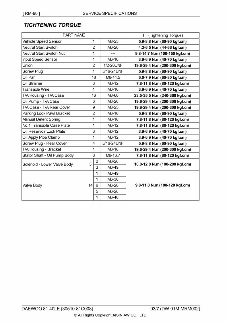
TIGHTENING TORQUE
TT (Tightening Torque)Vehicle Speed Sensor M8-25 5.9-8.8 N.m (60-90 kgf.cm)Neutral Start Switch M6-20 4.3-6.5 N.m (44-66 kgf.cm)Neutral Start Switch Nut --- 9.8-14.7 N.m (100-150 kgf.cm)Input Speed Sensor M6-16 3.9-6.9 N.m (40-70 kgf.cm)Union 1/2-20UNF 19.6-29.4 N.m (200-300 kgf.cm)Screw Plug 5/16-24UNF 5.9-8.8 N.m (60-90 kgf.cm)Oil Pan M6-14.5 6.0-7.9 N.m (60-80 kgf.cm)Oil Strainer M6-12 7.8-11.8 N.m (80-120 kgf.cm)Transaxle Wire M6-16 3.9-6.9 N.m (40-70 kgf.cm)T/A Housing - T/A Case M8-60 23.5-35.5 N.m (240-360 kgf.cm)Oil Pump - T/A Case M8-20 19.6-29.4 N.m (200-300 kgf.cm)T/A Case - T/A Rear Cover M8-25 19.6-29.4 N.m (200-300 kgf.cm)Parking Lock Pawl Bracket M6-16 5.9-8.8 N.m (60-90 kgf.cm)Manual Detent Spring M6-16 7.8-11.8 N.m (80-120 kgf.cm)No.1 Transaxle Case Plate M6-12 7.8-11.8 N.m (80-120 kgf.cm)Oil Reservoir Lock Plate M6-12 3.9-6.9 N.m (40-70 kgf.cm)Oil Apply Pipe Clamp M6-12 3.9-6.9 N.m (40-70 kgf.cm)Screw Plug - Rear Cover 5/16-24UNF 5.9-8.8 N.m (60-90 kgf.cm)T/A Housing - Bracket M8-16 19.6-29.4 N.m (200-300 kgf.cm)Stator Shaft - Oil Pump Body M6-16.7 7.8-11.8 N.m (80-120 kgf.cm)
2 M6-203 M6-491 M6-491 M6-366 M6-205 M6-281 M6-40
PART NAME
Solenoid - Lower Valve Body
Valve Body
121121183116692113141
14
10.0-12.0 N.m (100-200 kgf.cm)
9.8-11.8 N.m (100-120 kgf.cm)
8
5