1228 IEEE TRANSACTIONS ON ROBOTICS, VOL. 22, NO. … Collection/TRO... · Gravity-Balancing Leg...
12
1228 IEEE TRANSACTIONS ON ROBOTICS, VOL. 22, NO. 6, DECEMBER 2006 Gravity-Balancing Leg Orthosis and Its Performance Evaluation Sai K. Banala, Sunil K. Agrawal, Abbas Fattah, Vijaya Krishnamoorthy, Wei-Li Hsu, John Scholz, and Katherine Rudolph Abstract—In this paper, we propose a device to assist persons with hemiparesis to walk by reducing or eliminating the effects of gravity. The design of the device includes the following features: 1) it is passive, i.e., it does not include motors or actuators, but is only composed of links and springs; 2) it is safe and has a simple patient–machine interface to accommodate variability in geometry and inertia of the subjects. A number of methods have been pro- posed in the literature to gravity-balance a machine. Here, we use a hybrid method to achieve gravity balancing of a human leg over its range of motion. In the hybrid method, a mechanism is used to first locate the center of mass of the human limb and the orthosis. Springs are then added so that the system is gravity-balanced in every configuration. For a quantitative evaluation of the perfor- mance of the device, electromyographic (EMG) data of the key muscles, involved in the motion of the leg, were collected and ana- lyzed. Further experiments involving leg-raising and walking tasks were performed, where data from encoders and force-torque sen- sors were used to compute joint torques. These experiments were performed on five healthy subjects and a stroke patient. The re- sults showed that the EMG activity from the rectus femoris and hamstring muscles with the device was reduced by 75%, during static hip and knee flexion, respectively. For leg-raising tasks, the average torque for static positioning was reduced by 66.8% at the hip joint and 47.3% at the knee joint; however, if we include the transient portion of the leg-raising task, the average torque at the hip was reduced by 61.3%, and at the knee was increased by 2.7% at the knee joints. In the walking experiment, there was a positive impact on the range of movement at the hip and knee joints, espe- cially for the stroke patient: the range of movement increased by 45% at the hip joint and by 85% at the knee joint. We believe that this orthosis can be potentially used to design rehabilitation proto- cols for patients with stroke. Index Terms—Gait rehabilitation, gravity balancing, inverse dy- namics, passive orthosis, rehabilitation robotics. I. INTRODUCTION A VAST number of people are affected by conditions that re- sult in profound muscle weakness or impaired motor con- trol. People with severe muscle weakness from neurological in- jury, such as hemiparesis from stroke, often have substantial movement limitations. One of the aims of rehabilitation after stroke is to improve the walking function. However, equipment available to facilitate this is severely limited. Manuscript received December 23, 2005. This paper was recommended for publication by Associate Editor Q. Huang and Editor H. Arai upon evaluation of the reviewers’ comments. This work was supported by the National Institutes of Health under Grant 1 RO1 HD38582-01A2. This paper was presented in part at the IEEE International Conference on Robotics and Automation, 2004. Color versions of Figs. 3–21 are available at http://ieeexplore.org. S. K. Banala, S. K. Agrawal, and A. Fattah are with the Mechanical Systems Laboratory, Department of Mechanical Engineering, University of Delaware, Newark, DE 19716 USA (e-mail: [email protected]). J. Scholz, V. Krishnamoorthy, K. Rudolph, and W.-L. Hsu are with the De- partment of Physical Therapy, University of Delaware, Newark, DE 19716 USA. Digital Object Identifier 10.1109/TRO.2006.882928 Several lower-extremity rehabilitation machines have been developed recently to help retrain gait during walking. These machines are still not common in rehabilitation clinics. Lokomat is an actively powered exoskeleton, designed for patients with spinal cord injury. The patients use this machine while walking on a treadmill [1]. The Mechanized Gait Trainer (MGT) is a single degree-of-freedom (DOF) powered machine that drives the leg to move in a prescribed gait pattern. The machine consists of a foot plate connected to a crank and rocker system. The device simu- lates the phases of gait, supports the subjects according to their abilities, and controls the center of mass (COM) in the vertical and horizontal directions [2]. AutoAmbulator is a rehabilitation machine to assist individuals, with stroke and spinal cord in- juries, in leg motion impairments. This machine is designed to replicate the pattern of normal gait [3]. HAL [4] is a powered suit for elderly people and persons with gait disorders, which takes electromyographic (EMG) signals as input and produces appropriate torque to perform the task. A similar power-assisted exoskeleton device is Berkeley’s lower-extremety exoskeleton [5], though it is not intended as a rehabilitation device, but more as a human strength multiplier. The Pelvic Assist Manipulator (PAM) is an active device for assisting the human pelvis to allow naturalistic motion [6]. There are a variety of active devices that target a particular disability or weakness, and by repetitive mo- tion, try to regain the lost capability [7]–[11]. A limiting feature of these machines is that they move patients through predeter- mined movement patterns rather than allowing them to move undertheirowncontrol.Thefailuretoallowpatientstoexperience and practice appropriate movement patterns prevents necessary changes in the nervous system to promote relearning of typical patterns. Wilmington Robotic Exoskeleton (Training WREX or T-WREX) is a passive gravity-balanced device for retraining upper arm movement [12]. They have shown that gravity-bal- ancing appears to improve motor learning capability. However, to apply a wide variety of forces, Pneu-WREX was developed, which is a pneumatically actuated version of T-WREX [13]. Related work using this gravity-balancing device has focused on the effects of rehabilitation machines on postural stability during walking, and the nature of internal limb forces and mo- ments as different kinds of rehabilitation machines are added to the leg [14]. However, the work described in this paper fo- cuses on the design and performance evaluation of the specific gravity-balancing machine that we have fabricated and tested. In this paper, the performance of our gravity-balancing or- thosis is studied by measuring the EMG signals of the leg mus- cles involved and also by measuring force-torque data, which are described in detail later in this paper. Our leg orthosis is designed to assist persons with hemi- paresis to walk through elimination of the effects of gravity. 1552-3098/$20.00 © 2006 IEEE
Transcript of 1228 IEEE TRANSACTIONS ON ROBOTICS, VOL. 22, NO. … Collection/TRO... · Gravity-Balancing Leg...
1228 IEEE TRANSACTIONS ON ROBOTICS, VOL. 22, NO. 6, DECEMBER 2006
Gravity-Balancing Leg Orthosisand Its Performance Evaluation
Sai K. Banala, Sunil K. Agrawal, Abbas Fattah, Vijaya Krishnamoorthy, Wei-Li Hsu, John Scholz, andKatherine Rudolph
Abstract—In this paper, we propose a device to assist personswith hemiparesis to walk by reducing or eliminating the effects ofgravity. The design of the device includes the following features:1) it is passive, i.e., it does not include motors or actuators, but isonly composed of links and springs; 2) it is safe and has a simplepatient–machine interface to accommodate variability in geometryand inertia of the subjects. A number of methods have been pro-posed in the literature to gravity-balance a machine. Here, we usea hybrid method to achieve gravity balancing of a human leg overits range of motion. In the hybrid method, a mechanism is used tofirst locate the center of mass of the human limb and the orthosis.Springs are then added so that the system is gravity-balanced inevery configuration. For a quantitative evaluation of the perfor-mance of the device, electromyographic (EMG) data of the keymuscles, involved in the motion of the leg, were collected and ana-lyzed. Further experiments involving leg-raising and walking taskswere performed, where data from encoders and force-torque sen-sors were used to compute joint torques. These experiments wereperformed on five healthy subjects and a stroke patient. The re-sults showed that the EMG activity from the rectus femoris andhamstring muscles with the device was reduced by 75%, duringstatic hip and knee flexion, respectively. For leg-raising tasks, theaverage torque for static positioning was reduced by 66.8% at thehip joint and 47.3% at the knee joint; however, if we include thetransient portion of the leg-raising task, the average torque at thehip was reduced by 61.3%, and at the knee was increased by 2.7%at the knee joints. In the walking experiment, there was a positiveimpact on the range of movement at the hip and knee joints, espe-cially for the stroke patient: the range of movement increased by45% at the hip joint and by 85% at the knee joint. We believe thatthis orthosis can be potentially used to design rehabilitation proto-cols for patients with stroke.
Index Terms—Gait rehabilitation, gravity balancing, inverse dy-namics, passive orthosis, rehabilitation robotics.
I. INTRODUCTION
AVAST number of people are affected by conditions that re-sult in profound muscle weakness or impaired motor con-
trol. People with severe muscle weakness from neurological in-jury, such as hemiparesis from stroke, often have substantialmovement limitations. One of the aims of rehabilitation afterstroke is to improve the walking function. However, equipmentavailable to facilitate this is severely limited.
Manuscript received December 23, 2005. This paper was recommended forpublication by Associate Editor Q. Huang and Editor H. Arai upon evaluationof the reviewers’ comments. This work was supported by the National Institutesof Health under Grant 1 RO1 HD38582-01A2. This paper was presented in partat the IEEE International Conference on Robotics and Automation, 2004. Colorversions of Figs. 3–21 are available at http://ieeexplore.org.
S. K. Banala, S. K. Agrawal, and A. Fattah are with the Mechanical SystemsLaboratory, Department of Mechanical Engineering, University of Delaware,Newark, DE 19716 USA (e-mail: [email protected]).
J. Scholz, V. Krishnamoorthy, K. Rudolph, and W.-L. Hsu are with the De-partment of Physical Therapy, University of Delaware, Newark, DE 19716 USA.
Digital Object Identifier 10.1109/TRO.2006.882928
Several lower-extremity rehabilitation machines have beendeveloped recently to help retrain gait during walking. Thesemachines are still not common in rehabilitation clinics. Lokomatis an actively powered exoskeleton, designed for patients withspinal cord injury. The patients use this machine while walkingona treadmill [1].TheMechanizedGaitTrainer (MGT)isasingledegree-of-freedom (DOF) powered machine that drives the leg tomove in a prescribed gait pattern. The machine consists of a footplate connected to a crank and rocker system. The device simu-lates the phases of gait, supports the subjects according to theirabilities, and controls the center of mass (COM) in the verticaland horizontal directions [2]. AutoAmbulator is a rehabilitationmachine to assist individuals, with stroke and spinal cord in-juries, in leg motion impairments. This machine is designed toreplicate the pattern of normal gait [3]. HAL [4] is a poweredsuit for elderly people and persons with gait disorders, whichtakes electromyographic (EMG) signals as input and producesappropriate torque to perform the task. A similar power-assistedexoskeleton device is Berkeley’s lower-extremety exoskeleton[5], though it is not intended as a rehabilitation device, but moreas a human strength multiplier. The Pelvic Assist Manipulator(PAM) is an active device for assisting the human pelvis to allownaturalistic motion [6]. There are a variety of active devices thattarget a particular disability or weakness, and by repetitive mo-tion, try to regain the lost capability [7]–[11]. A limiting featureof these machines is that they move patients through predeter-mined movement patterns rather than allowing them to moveundertheirowncontrol.Thefailuretoallowpatients toexperienceand practice appropriate movement patterns prevents necessarychanges in the nervous system to promote relearning of typicalpatterns. Wilmington Robotic Exoskeleton (Training WREX orT-WREX) is a passive gravity-balanced device for retrainingupper arm movement [12]. They have shown that gravity-bal-ancing appears to improve motor learning capability. However,to apply a wide variety of forces, Pneu-WREX was developed,which is a pneumatically actuated version of T-WREX [13].
Related work using this gravity-balancing device has focusedon the effects of rehabilitation machines on postural stabilityduring walking, and the nature of internal limb forces and mo-ments as different kinds of rehabilitation machines are addedto the leg [14]. However, the work described in this paper fo-cuses on the design and performance evaluation of the specificgravity-balancing machine that we have fabricated and tested.
In this paper, the performance of our gravity-balancing or-thosis is studied by measuring the EMG signals of the leg mus-cles involved and also by measuring force-torque data, whichare described in detail later in this paper.
Our leg orthosis is designed to assist persons with hemi-paresis to walk through elimination of the effects of gravity.
1552-3098/$20.00 © 2006 IEEE

BANALA et al.: GRAVITY-BALANCING LEG ORTHOSIS AND ITS PERFORMANCE EVALUATION 1229
The proposed device is designed to be passive. The mainreason why we chose a passive device is because of safety.Usually, patients are more comfortable and feel safer gettinginto a passive device than an active one. Second, we intend touse this device as a rehabilitation device, helping patients intraining their muscles and regaining their former control andstrength. This device has the following features: 1) it can fullyor partially gravity-balance the human leg over the range of itsmotion; 2) it is tunable to the geometry and inertia of a specifichuman subject to achieve the desired level of gravity balancing.This orthosis can be potentially used as a rehabilitation devicefor individuals with severe muscle weakness. The target pop-ulation will consist of persons who have motion impairmentsfrom stroke. The assistance to movement will be lowered as thepatient progresses. The improved ability to walk will restorepatient independence, lessen the need for assisted living, mayallow people to integrate back into society, and return to work.
Gravity balancing has been used in industries for a varietyof robotic applications. In this paper, our design uses a hybridmethod to balance the weight of the leg in all configurations. Itputs the leg in a state of neutral equilibrium everywhere duringmotion [15]. To check the practical feasibility of the device,a wooden prototype was first fabricated. Then, an engineeringprototype using aluminum was made. For a quantitative eval-uation of the performance of the device, EMG data of the keymuscles involved in the motion of the leg was collected and ana-lyzed. This study was performed on five healthy subjects. Also,an inverse-dynamics study was performed with the force-torquedata obtained from the sensors used at the interface of the deviceand the subject leg. In conjunction with a walking frame and anoverhead safety harness, we believe that this device can be usedas an effective orthosis for rehabilitation.
II. THEORY
The principle involved in gravity-balancing the leg with thehybrid method is as follows [16]: 1) the COM of the leg is ge-ometrically located using a parallelogram mechanism; 2) thesprings are placed at suitable positions so that they completelybalance the effect of gravity over the range of motion. In thissection, the two concepts are described in more detail.
A. Locating the COM
In the current design, we consider only two segments of theleg and approximate the foot as a point mass. These two seg-ments are the thigh and the shank.
A sketch of the mechanism along with springs is shown inFig. 1. A schematic diagram of this mechanism is shown inFig. 2. The segments OA and AB are the primary links of theorthosis, whereas DC and CE are the auxiliary links. The massat the joints are approximated as point masses , , and
. The point mass also includes the weight of the foot.Let us define the following terms:
length of the th link;distance of the COM of the th primary link fromthe joint on the previous link;distance of the COM of the th auxiliary link fromthe joint on the previous link;
Fig. 1. Basic components of gravity-balancing mechanism.
Fig. 2. Various terms and parameters of gravity-balancing mechanism.
mass of the th primary link (mass of the legsegment included);mass of the th auxiliary link;mass of the th point mass;unit vector along the th primary link;position vector from the point O to the COM ofthe th primary link;position vector from the point O to the COM ofthe th auxiliary link;position vector from the point O to the COM ofthe th point mass;distance OD in Fig. 2;distance AE in Fig. 2.
1230 IEEE TRANSACTIONS ON ROBOTICS, VOL. 22, NO. 6, DECEMBER 2006
Among all these quantities, only , , and are unknownvariables. Also, if we assume that the auxiliary links are made oftelescopic members, their mass remains constant, independentof their length. would become a linear function of the lengthof the th auxiliary link. Hence, the only remaining unknownquantities are . Let
(1)
where and are the ratios between 0 and 1. The COM ofthe whole mechanism is given by
(2)
where
(3)
(4)
(5)
Let us write the vectors , , and in terms of unit vectorsalong the primary links in the following:
(6)
Since C is the COM of the entire mechanism, can bewritten as .
On substituting for , , , , , and into (2) andsolving for and , we get
(7)
Hence, with the values of and given by (7), the COM ofthe whole mechanism, including the human leg, can be locatedand tracked in every configuration. It is important to point outthat and are proportional to the lengths of primary links
and , respectively, hence the name scaled lengths [15]. Weexpect that the scaled lengths are functions of the distribution ofthe mass.
B. Gravity Balancing
Gravity balancing is achieved using springs located on themechanism, as shown in Fig. 2. Our designs use zero free-lengthsprings, i.e., the rest lengths of the springs are zero. A zero free-
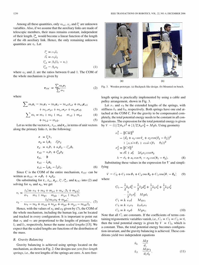
Fig. 3. Wooden prototype. (a) Backpack-like design. (b) Mounted on bench.
length spring is practically implemented by using a cable andpulley arrangement, shown in Fig. 3.
Let and be the extended lengths of the springs, withstiffness and , respectively. Both springs have one end at-tached at the COM C. For the gravity to be compensated com-pletely, the total potential energy needs to be constant in all con-figurations. The expression for the total potential energy is givenby . Using geometry
(8)
Substituting these values in the expression for and simpli-fying
(9)
where
(10)
Note that all are constants. If the coefficients of terms con-taining trigonometric variables vanish, i.e., ,then the total potential energy is given by , which isa constant. Thus, the total potential energy becomes configura-tion-invariant, and the gravity balancing is achieved. These con-ditions yield two independent equations
(11)

BANALA et al.: GRAVITY-BALANCING LEG ORTHOSIS AND ITS PERFORMANCE EVALUATION 1231
Hence, if two zero free-length springs with stiffness given by(11) are used, the mechanism would become gravity-balanced.Equation (10) shows that the first spring compensates for thegravity force of the total system, and helps to make thepotential energy invariant with configuration. and are ar-bitrary variables, and can be chosen to vary the level of gravity-balancing.
III. DESIGN
We fabricated two prototypes based on this concept, withwood to test the practical feasibility, and with aluminum to testthe effectiveness of the design.
A. Wooden Prototype
The first design was intended to be worn by a person whilewalking freely [17]. This prototype is shown in Fig. 3(a). Inthis design, the weight of the leg is taken by the trunk whileusing this mechanism. Additionally, the weight of the leg andthe orthosis can be transmitted to a work bench or a walkingframe through the arrangement shown in Fig. 3(b). In Fig. 3(b),an additional vertical translation DOF has been added to theback support system using a parallelogram mechanism, shownin the figure. This interface device could be attached to a walkingframe or a treadmill frame so that the forces and torques fromthe orthosis are transmitted to the frame.
B. Engineering Prototype
An engineering prototype was fabricated in-house, based onpreliminary feedback on the wooden prototype from the phys-ical therapy members of the research team. This prototype hasthe following features: 1) limbs of the machine are made out oflightweight aluminum. Ball bearings are used at the knee andhip joints, and bronze bearings are used at the other joints; 2)limbs are made to be telescopic to accommodate variability inthe leg dimensions and inertia across human subjects; 3) thespring locations are adjustable to change the level of gravityduring motion, between zero and one gravity; 4) the machineis connected to a walking frame; 5) the backpack attachment tothe trunk and the limb attachments to the leg are molded to con-form to the contours of a human subject; 6) additional flexibilityfor the trunk to rotate about a vertical axis is introduced, besidesvertical motion.
A picture of the engineering prototype, along with thewalking frame and a subject, is shown in Fig. 4. Please notethat the white box visible in the figure contains the springsand the pulleys. This initial prototype brought out some usefulengineering and clinically relevant observations: 1) the sub-jects perceived resistance to straightening of the knee (i.e.,extension), perhaps due to friction, and too much assistanceto bending (i.e., flexion), that pulled the knee into flexion; 2)there is a lateral resistance when straightening the knee fromthe attachment point of the shank casing with the aluminumbar of the prototype. The lower leg abducts (moves outward)very slightly (about 5 –10 ) when the knee is straightened,probably because of the congruency of the surfaces at the knee.Although this is only a slight motion, the lack of lateral “give”
Fig. 4. Engineering prototype mounted on the walking frame and the subjectin the gravity-balancing device.
Fig. 5. Position of encoders (E1 and E2) and force-torque sensors (S1 and S2)on the device.
of the robot joint caused mild pressure on the lateral fibula;3) since the device allowed motion in the saggital plane, notallowing any adduction, and there was a limited amount ofpelvic translation allowed, the body tended to shift to the leftduring weight-bearing on the limb wearing the device; 4) thethigh and shank segments in the robot are oriented vertically,while the same segments of the human have some degree ofvalgus at the knee.
Modifications were made to this prototype based on this feed-back. Additional DOFs were introduced at the hip and the pelvisto incorporate pelvic translation and hip abduction/adduction.The anatomical configuration for the thigh segment was incor-porated by angling it medially (inward) at the distal end. Bronzebearings were replaced with ball bearings to further reduce thefriction. The modified prototype is shown in Fig. 5.
1232 IEEE TRANSACTIONS ON ROBOTICS, VOL. 22, NO. 6, DECEMBER 2006
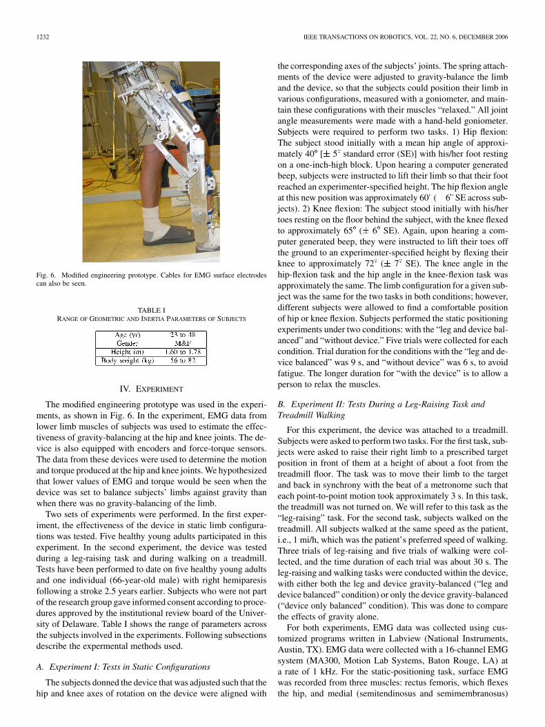
Fig. 6. Modified engineering prototype. Cables for EMG surface electrodescan also be seen.
TABLE IRANGE OF GEOMETRIC AND INERTIA PARAMETERS OF SUBJECTS
IV. EXPERIMENT
The modified engineering prototype was used in the experi-ments, as shown in Fig. 6. In the experiment, EMG data fromlower limb muscles of subjects was used to estimate the effec-tiveness of gravity-balancing at the hip and knee joints. The de-vice is also equipped with encoders and force-torque sensors.The data from these devices were used to determine the motionand torque produced at the hip and knee joints. We hypothesizedthat lower values of EMG and torque would be seen when thedevice was set to balance subjects’ limbs against gravity thanwhen there was no gravity-balancing of the limb.
Two sets of experiments were performed. In the first exper-iment, the effectiveness of the device in static limb configura-tions was tested. Five healthy young adults participated in thisexperiment. In the second experiment, the device was testedduring a leg-raising task and during walking on a treadmill.Tests have been performed to date on five healthy young adultsand one individual (66-year-old male) with right hemiparesisfollowing a stroke 2.5 years earlier. Subjects who were not partof the research group gave informed consent according to proce-dures approved by the institutional review board of the Univer-sity of Delaware. Table I shows the range of parameters acrossthe subjects involved in the experiments. Following subsectionsdescribe the expermental methods used.
A. Experiment I: Tests in Static Configurations
The subjects donned the device that was adjusted such that thehip and knee axes of rotation on the device were aligned with
the corresponding axes of the subjects’ joints. The spring attach-ments of the device were adjusted to gravity-balance the limband the device, so that the subjects could position their limb invarious configurations, measured with a goniometer, and main-tain these configurations with their muscles “relaxed.” All jointangle measurements were made with a hand-held goniometer.Subjects were required to perform two tasks. 1) Hip flexion:The subject stood initially with a mean hip angle of approxi-mately 40 [ 5 standard error (SE)] with his/her foot restingon a one-inch-high block. Upon hearing a computer generatedbeep, subjects were instructed to lift their limb so that their footreached an experimenter-specified height. The hip flexion angleat this new position was approximately 60 ( 6 SE across sub-jects). 2) Knee flexion: The subject stood initially with his/hertoes resting on the floor behind the subject, with the knee flexedto approximately 65 ( 6 SE). Again, upon hearing a com-puter generated beep, they were instructed to lift their toes offthe ground to an experimenter-specified height by flexing theirknee to approximately 72 ( 7 SE). The knee angle in thehip-flexion task and the hip angle in the knee-flexion task wasapproximately the same. The limb configuration for a given sub-ject was the same for the two tasks in both conditions; however,different subjects were allowed to find a comfortable positionof hip or knee flexion. Subjects performed the static positioningexperiments under two conditions: with the “leg and device bal-anced” and “without device.” Five trials were collected for eachcondition. Trial duration for the conditions with the “leg and de-vice balanced” was 9 s, and “without device” was 6 s, to avoidfatigue. The longer duration for “with the device” is to allow aperson to relax the muscles.
B. Experiment II: Tests During a Leg-Raising Task andTreadmill Walking
For this experiment, the device was attached to a treadmill.Subjects were asked to perform two tasks. For the first task, sub-jects were asked to raise their right limb to a prescribed targetposition in front of them at a height of about a foot from thetreadmill floor. The task was to move their limb to the targetand back in synchrony with the beat of a metronome such thateach point-to-point motion took approximately 3 s. In this task,the treadmill was not turned on. We will refer to this task as the“leg-raising” task. For the second task, subjects walked on thetreadmill. All subjects walked at the same speed as the patient,i.e., 1 mi/h, which was the patient’s preferred speed of walking.Three trials of leg-raising and five trials of walking were col-lected, and the time duration of each trial was about 30 s. Theleg-raising and walking tasks were conducted within the device,with either both the leg and device gravity-balanced (“leg anddevice balanced” condition) or only the device gravity-balanced(“device only balanced” condition). This was done to comparethe effects of gravity alone.
For both experiments, EMG data was collected using cus-tomized programs written in Labview (National Instruments,Austin, TX). EMG data were collected with a 16-channel EMGsystem (MA300, Motion Lab Systems, Baton Rouge, LA) ata rate of 1 kHz. For the static-positioning task, surface EMGwas recorded from three muscles: rectus femoris, which flexesthe hip, and medial (semitendinosus and semimembranosus)
BANALA et al.: GRAVITY-BALANCING LEG ORTHOSIS AND ITS PERFORMANCE EVALUATION 1233
and lateral (biceps femoris) hamstring muscles, which flex theknee [18], [19]. The iliopsoas muscle is the primary hip flexor.However, because of this muscle’s depth, signals cannot be reli-ably obtained using surface EMG recordings. Therefore, to limitthe usage to surface electrodes, we recorded the rectus femorismuscle, which is also a powerful hip flexor as well as a knee ex-tensor. For the leg-raising and walking tasks, EMG from vastusmedialis and vastus lateralis (extensors of the knee) were col-lected, in addition to the muscles mentioned above.
The EMG recording electrodes with integrated preamplifierswere placed over the bulk of the muscle belly in the direction ofthe muscle fibers. The centers of the two poles of the electrodeswere fixed at 2 cm apart. The EMG signals were preamplifiedx 20. Offline, the EMG signals were rectified and lowpass fil-tered with a second-order Butterworth filter at a 15 Hz cutofffrequency. Further, for the static task, the EMG data were inte-grated over a 1 s time interval, once the limb was in a final restingor elevated position. The device has digital encoders at hip andknee joints. Force-torque sensors are mounted at the interface ofhuman leg and device, one between the thigh segment of the de-vice and the thigh of the subject, the second between the shanksegment of the device and the shank of the subject. Data fromthese were collected by using a D-Space system at 1 kHz sam-pling rate. The noise from the force-torque sensors was reducedby using a Butterworth second-order filter at a cutoff frequencyof 16 Hz. The encoders and sensors on the device are shown inFig. 5.
V. MEASURING JOINT TORQUES
Using data from encoders and force-torque sensors, we candetermine the torques applied by the subject at the hip and kneejoints by using dynamic force and moment balancing. Followingare the terms used in equations:
linear acceleration at point P;
mass of human thigh;
mass of human shank;
weight of human thigh ;
weight of human shank ;
moment of inertia of human thigh about its COM;
moment of inertia of human shank about its COM;
interfacial force and moment at human thigh;
interfacial force and moment at human shank;
reaction force and moment at human hip joint;
reaction force and moment at human knee joint;
COM of human thigh;
COM of human shank;
position vector from point A to the point ofapplication of force F.
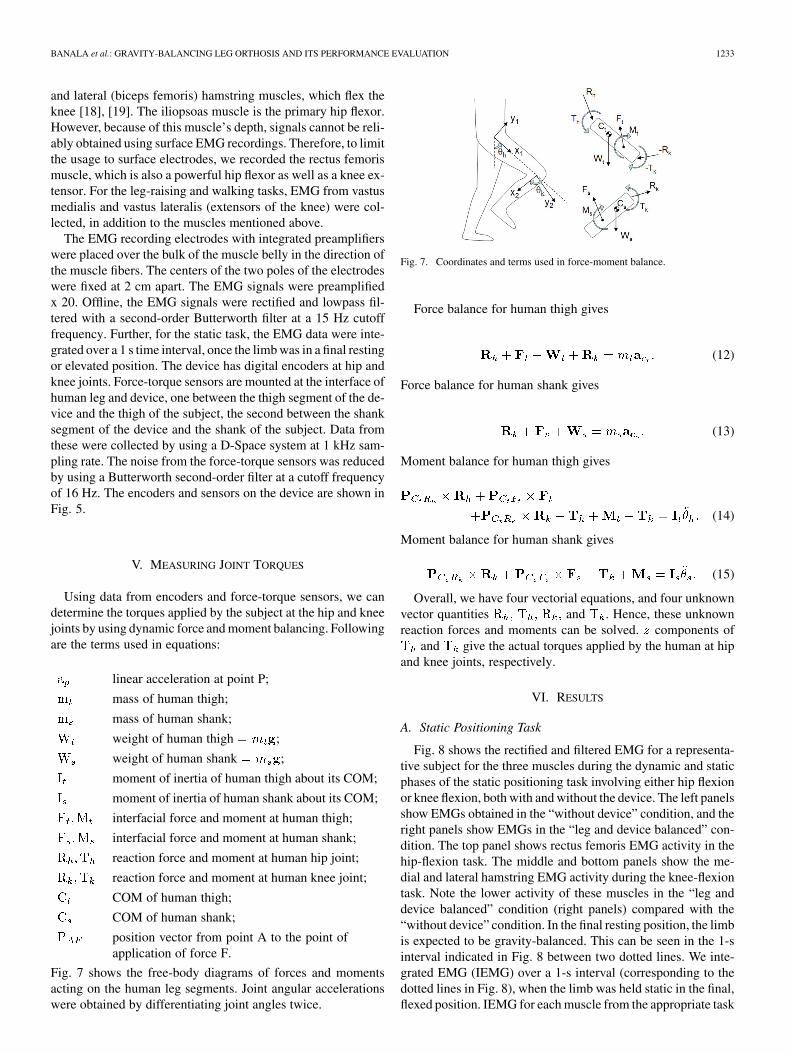
Fig. 7 shows the free-body diagrams of forces and momentsacting on the human leg segments. Joint angular accelerationswere obtained by differentiating joint angles twice.
Fig. 7. Coordinates and terms used in force-moment balance.
Force balance for human thigh gives
(12)
Force balance for human shank gives
(13)
Moment balance for human thigh gives
(14)
Moment balance for human shank gives
(15)
Overall, we have four vectorial equations, and four unknownvector quantities and . Hence, these unknownreaction forces and moments can be solved. components of
and give the actual torques applied by the human at hipand knee joints, respectively.
VI. RESULTS
A. Static Positioning Task
Fig. 8 shows the rectified and filtered EMG for a representa-tive subject for the three muscles during the dynamic and staticphases of the static positioning task involving either hip flexionor knee flexion, both with and without the device. The left panelsshow EMGs obtained in the “without device” condition, and theright panels show EMGs in the “leg and device balanced” con-dition. The top panel shows rectus femoris EMG activity in thehip-flexion task. The middle and bottom panels show the me-dial and lateral hamstring EMG activity during the knee-flexiontask. Note the lower activity of these muscles in the “leg anddevice balanced” condition (right panels) compared with the“without device” condition. In the final resting position, the limbis expected to be gravity-balanced. This can be seen in the 1-sinterval indicated in Fig. 8 between two dotted lines. We inte-grated EMG (IEMG) over a 1-s interval (corresponding to thedotted lines in Fig. 8), when the limb was held static in the final,flexed position. IEMG for each muscle from the appropriate task

1234 IEEE TRANSACTIONS ON ROBOTICS, VOL. 22, NO. 6, DECEMBER 2006
Fig. 8. Rectified and filtered EMG for a representative subject for the three muscles during the dynamic and static phases in two conditions, “without the device”and with “leg and device balancing.”
(hip flexion for rectus femoris and knee flexion for the medialand lateral hamstrings) in a subject was normalized to the max-imum IEMG obtained from the five trials in the “without device”condition in that subject. These normalized IEMG indices werethen expressed as a percentage of the highest IEMG from the“without device” condition. Thus, we expect to see low IEMGpercentage values for the “leg and device balanced” condition,and high IEMG percentage values for the “without device” con-dition. Fig. 9 shows these IEMG percentages averaged acrossthe five subjects with error bars. The blue bars represent the“leg and device balanced” condition, and the gray bars repre-sent the “without device” condition. The left two bars are re-sults for the rectus femoris in the hip-flexion task. The middleand right two sets of bars are the results for the medial and lat-eral hamstring muscles, respectively, for the knee-flexion task.Note that the IEMG percentages for the “leg and device bal-anced” condition were always lower than for the “without de-vice” condition. These differences were significantwhen tested with a paired t-test for each muscle. Because the av-erage maximum EMG values for the “without device” conditionwere around 75%–80% (recall that all trials were normalized tothe maximum EMG value for the trial showing the highest ac-tivity), subjects were not consistent in the amount of EMG ac-tivation that they used to flex the hip or knee. This could be dueto differences in the contribution of other unmeasured muscles(e.g., iliopsoas) on some trials or greater co-contraction on sometrials.
Complete gravity-balancing of the leg and device should haveled to zero EMG activity in the recorded muscles in the static po-sition with the device. In fact, although the EMG activity was
Fig. 9. IEMG percentages averaged across the five subjects for stepping task,with error bars.
substantially and significantly lower in this condition, it was notzero. There may be several explanations for this result. First,while it is possible, in principle, to completely gravity-balancethe limb and device, this may be difficult, in practice. For ex-ample, factors such as the passive elasticity of the muscles andother soft tissue are not completely taken into account in the cur-rent model for balancing the limb. In addition, it may be verydifficult for healthy subjects, i.e., without any impairment, tocompletely relax the muscles of the limb after minimal exposureto the device. This possibility was borne out by the commentsof several of the participants, who reported that it was “strange”

BANALA et al.: GRAVITY-BALANCING LEG ORTHOSIS AND ITS PERFORMANCE EVALUATION 1235
Fig. 10. Joint angles of a representative subject during leg-raising task. Flx:Flexion, Ext: Extension.
to think about lifting the leg up in mid-air and having it staythere while completely relaxed. This suggests that in order forusers to completely relax their muscles and allow the device tomaximally “help” them, adequate practice is essential. Our de-vice was designed in consultation with an orthotist to ensure thatthe design of the attachments of our orthosis to the human limbwas appropriate. However, all orthotic devices interface with thelimb through varying amounts of soft tissue and, therefore, theattachments are not rigid. The soft tissue prevents a precise po-sitioning of the segments, making it difficult to achieve 100%gravity balancing in practice. Nonetheless, the results indicatethat the device dramatically diminished the amount of muscleactivity required for these static positioning tasks.
B. Leg-Raising Task
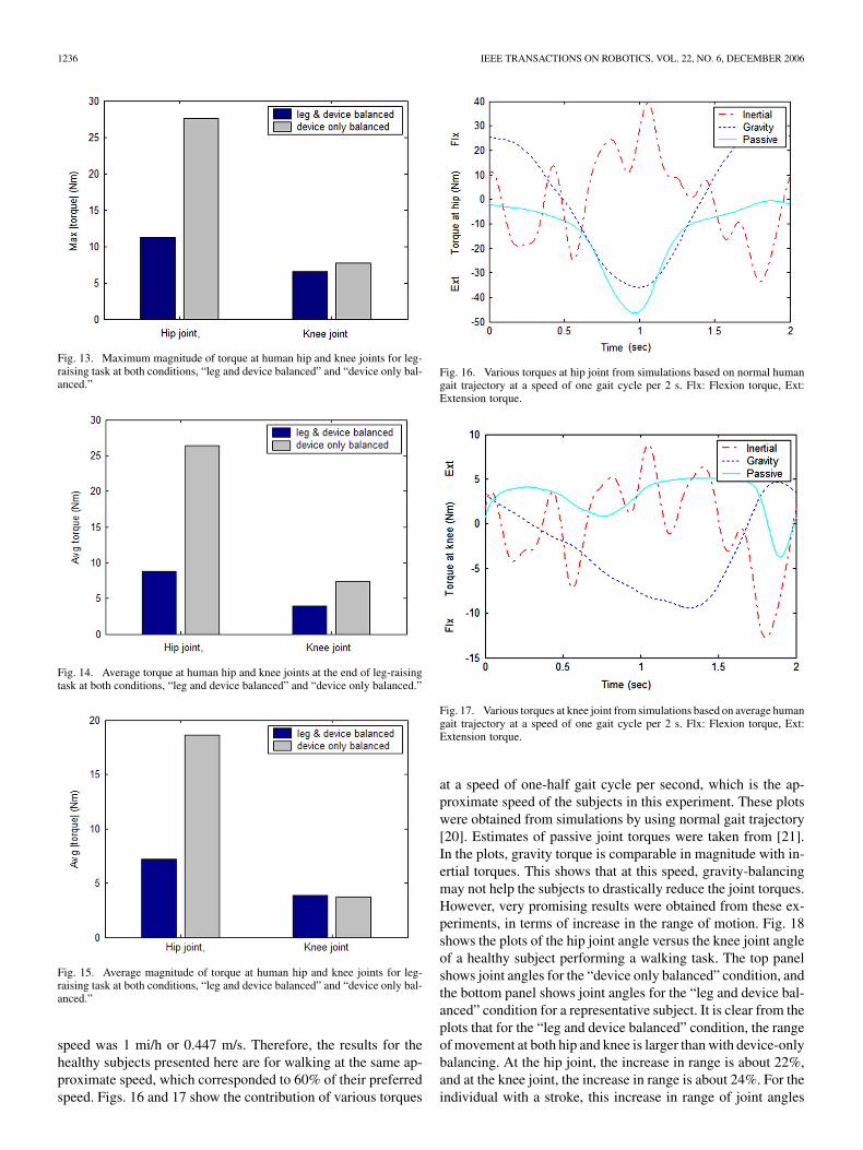
In the figures that follow, “leg and device balanced” refersto the condition where both the leg and device are gravity-bal-anced. The designation “device only balanced” refers to thecondition where only the device, but not the weight of theleg, is balanced. Fig. 10 shows the joint angles obtained fromoptical encoders. It shows three cycles of leg-raising motion.Figs. 11 and 12 show human joint torques in the “device andleg balanced” and “device only balanced” conditions obtainedusing inverse dynamics with force-torque and encoder data, asexplained in the previous section. These plots are for a singletrial of one subject’s data. Fig. 13 shows the peak value ofthe joint torques. Gravity-balancing led to a 59.5% and 14.3%decrease in peak hip and knee joint torques, respectively.Fig. 14 shows the mean of human joint torques taken when theleg reaches the target position of the leg-raising motion. Thisregion corresponds to 12.5–13.7 s in joint trajectories, shownin Fig. 10. This is similar to averaging done in EMG plotsshown in Fig. 9 for the static positioning task. As in the caseof EMG, here too the reduction in joint torque at hip and kneewith gravity-balancing of the leg is about 66.8% and 47.3%,respectively. Fig. 15 shows the average of magnitude of torqueat hip and knee joints over a period of one complete leg-raisingtask, including both transient and static phases. This periodis from 10.7 s to 16.25 s in Fig. 10. In this case, the hip joint
Fig. 11. Torque at human hip joint for leg-raising task at both conditions, “legand device balanced” and “device only balanced.” Flx: Flexion torque, Ext: Ex-tension torque.
Fig. 12. Torque at human knee joint for leg-raising task at both conditions,“leg and device balanced” and “device only balanced.” Flx: Flexion torque, Ext:Extension torque.
torque is reduced approximately 61.3%, while knee torqueincreased by approximately 2.7% with gravity-balancing ofthe leg. One possible reason for this increase in torque at theknee could be the contribution from passive elastic forces in themuscles around the knee joint. Another possible reason couldbe friction in the joints. This friction is a result of contributionfrom four joints, the knee joint and three joints of auxiliarylinks [16]. Second, the magnitude of torque at the knee joint iscomparably smaller than the magnitudes of torque at the hipjoint; as a result, the contribution to error from undesirableeffects were more apparent in the knee joint torque.
C. Treadmill Walking Task
The healthy subjects also walked at several different speedson a treadmill while wearing the device under both “leg and de-vice balanced” and “device only balanced” conditions. At thispoint, we also recruited an individual with right hemiparesis toparticipate in the walking trials. The patient’s preferred walking
1236 IEEE TRANSACTIONS ON ROBOTICS, VOL. 22, NO. 6, DECEMBER 2006
Fig. 13. Maximum magnitude of torque at human hip and knee joints for leg-raising task at both conditions, “leg and device balanced” and “device only bal-anced.”
Fig. 14. Average torque at human hip and knee joints at the end of leg-raisingtask at both conditions, “leg and device balanced” and “device only balanced.”
Fig. 15. Average magnitude of torque at human hip and knee joints for leg-raising task at both conditions, “leg and device balanced” and “device only bal-anced.”
speed was 1 mi/h or 0.447 m/s. Therefore, the results for thehealthy subjects presented here are for walking at the same ap-proximate speed, which corresponded to 60% of their preferredspeed. Figs. 16 and 17 show the contribution of various torques
Fig. 16. Various torques at hip joint from simulations based on normal humangait trajectory at a speed of one gait cycle per 2 s. Flx: Flexion torque, Ext:Extension torque.
Fig. 17. Various torques at knee joint from simulations based on average humangait trajectory at a speed of one gait cycle per 2 s. Flx: Flexion torque, Ext:Extension torque.
at a speed of one-half gait cycle per second, which is the ap-proximate speed of the subjects in this experiment. These plotswere obtained from simulations by using normal gait trajectory[20]. Estimates of passive joint torques were taken from [21].In the plots, gravity torque is comparable in magnitude with in-ertial torques. This shows that at this speed, gravity-balancingmay not help the subjects to drastically reduce the joint torques.However, very promising results were obtained from these ex-periments, in terms of increase in the range of motion. Fig. 18shows the plots of the hip joint angle versus the knee joint angleof a healthy subject performing a walking task. The top panelshows joint angles for the “device only balanced” condition, andthe bottom panel shows joint angles for the “leg and device bal-anced” condition for a representative subject. It is clear from theplots that for the “leg and device balanced” condition, the rangeof movement at both hip and knee is larger than with device-onlybalancing. At the hip joint, the increase in range is about 22%,and at the knee joint, the increase in range is about 24%. For theindividual with a stroke, this increase in range of joint angles

BANALA et al.: GRAVITY-BALANCING LEG ORTHOSIS AND ITS PERFORMANCE EVALUATION 1237
Fig. 18. Hip-joint angle versus knee-joint angle plot of healthy subjects fromwalking tasks. Data for several gait cycles is shown.
was more prominent than in healthy subjects. Fig. 19 shows thejoint angles for the patient. The increase in the range of jointangles is 45% at the hip joint and 85% at the knee joint. Fur-thermore, the patient voluntarily reported that the device helpedhim in moving his joints against gravity and allowed him to takelonger steps. Actual estimation of the step length showed thatthe average increase in step length is 5.73%. The increase inamplitude of gait trajectory for the stroke subject is an impor-tant positive effect of gravity balancing.
Fig. 20 shows joint torques for the walking task averagedover all trials of one healthy subject in the “leg and device bal-anced” and “device only balanced” conditions. These plots arenormalized time over swing phase. In the stance phase, the sub-ject is not moving the leg against gravity; hence, gravity-bal-ancing does not make much difference (even though gravity ofthe leg is compensated). In this plot, torque at the hip joint issmaller for the “leg and device balanced” condition, comparedwith the “device only balanced” condition, for most of the swingphase. However, the knee joint does not show this reduction intorque, and, in fact, shows an increase in torque. Fig. 21 showsthe joint torques averaged over all trials of the stroke patient.Here, the joint torques did not show a decrease in the “leg anddevice balanced” condition. As explained earlier, at the speedat which subjects are walking, inertial torque plays a significantrole. Hence, gravity-balancing alone is likely inadequate to re-duce the torque magnitudes. In addition, the passive elasticityof the muscles across human joints and friction in the joints ofthe machine could be the contributing factors, which are not ac-counted for here. The patterns of muscle activation in individ-
Fig. 19. Hip-joint angle versus knee-joint angle plot of the stroke subject fromwalking tasks. Data for several gait cycles is shown.
Fig. 20. Joint torques (and its standard deviation) for walking task averagedover all trials of a representative subject.
uals with stroke are known to be different from healthy subjects,and may contribute to the lack of an effect of the device on jointtorques. In both the leg-raising and walking tasks, the EMGsalso did not show differences between the “leg and device bal-anced” and “device only balanced” conditions. Despite the lackof effects related to EMG and torque for the stroke subject, how-ever, the increase in range of motion of the joints that resultedfrom gravity-balancing of the leg and device has important im-plications for improvement in the patient’s gait pattern.
VII. DISCUSSION
The main purpose of this device is to minimize the effort re-quired to lift the lower limbs against gravity. Patients having

1238 IEEE TRANSACTIONS ON ROBOTICS, VOL. 22, NO. 6, DECEMBER 2006
Fig. 21. Joint torques (and its standard deviation) for walking task averagedover all trails of the stroke patient.
weakness of muscles can be expected to benefit from this de-vice, since this device takes away a major source of resistanceto their movement, particularly at relatively slow gait speeds.Careful selection of patients who might benefit from this de-vice is required. The ideal patient likely to obtain maximal ben-efit would be an individual with slow gait and weakness of theleg muscles, such that elimination of gravity would allow themto use their available muscle activation to transport the limbwithout requiring additional assistance in the form of motors,etc. At present, the device does not compensate for forces suchas interaction moments that result from limb dynamics. Thus,for relatively rapid gait speeds, gravity-balancing alone may beinadequate.
In future versions of the device, we plan to compensate forother forces, such as the passive elasticity of the muscles andsoft tissue, by modeling these forces and incorporating com-pensations for them. This study represents an attempt to testthe effect of gravity-balancing on muscle activation during staticand dynamic tasks. Our tests show that the device generally suc-ceeds in its intended purpose. More detailed studies of its effecton muscle activation and joint torques during gait are currentlyunderway, in parallel with improvements in the device design,to allow movement assistance, where needed, by the addition ofmotors.
The rationale for the device is that many patients who havesuffered a stroke have both primary and secondary muscleweakness, which leads to atypical patterns of muscle activationand resulting movement to compensate for their weaknesswhile still achieving a degree of function [22]. We hypoth-esize that removing or lessening the weight of the limb willmake it easier for the patient to move the limb, and may helppatients practice functional movement patterns without theneed to develop such compensations, or at least, to limit theirextent. This would allow the patient to practice leg movementsindependently and in the context of locomotion using morenormal muscle activation patterns. As the most affected mus-cles become stronger through such exercise, the amount ofgravity compensation can be reduced to increase the load onthe muscles and further improve their strength. In this way, we
hope to provide a mechanism by which patients can improvefunction without developing atypical compensations, whichare often very difficult to unlearn when more normal musclestrength returns. This device will provide a means for testingthis hypothesis.
VIII. CONCLUSION
In this paper, a leg orthosis was presented that is designedto assist persons with hemiparesis to walk by eliminating theeffects of gravity. An engineering metallic prototype was fab-ricated using aluminum. This aluminum prototype was mod-ified and used in the experiment to check its effectiveness ingravity-balancing. In the experiment, EMG data of the key mus-cles of the hip and knee were collected and analyzed. This studywas performed on five healthy subjects and an individual withright hemiparesis following a stroke. The results showed thatthe average maximum EMG value for the “leg and device bal-anced” condition was around 25% of the EMG value for the“without device” conditions for the static experiment. For leg-raising tasks, the average torque at static positioning (at the endof the task) reduced by 66.8% at the hip joint and 47.3% at theknee joint. However, if we include the transient portion of theleg-raising task, the average torque at the hip reduced by 61.3%,and at the knee increased by 2.7%, at knee joints. In the walkingexperiment, gravity-balancing improved only hip joint torquesin the healthy subjects. EMGs were not affected by gravity-bal-ancing. However, there was a positive impact on the range ofmovement at the hip and knee joints, especially for the strokepatient: the range increased by 45% at the hip joint and by 85%at the knee joint. We believe that this orthosis can be a potentialrehabilitation device for individuals with severe muscle weak-ness.
ACKNOWLEDGMENT
The authors would like to acknowledge A. Agrawal’s help infabrication of the device.
REFERENCES
[1] G. Colombo, M. Joerg, R. Schreier, and V. Dietz, “Treadmill trainingof paraplegic patients using a robotic orthosis,” J. Rehab. Res. Dev.,vol. 37, no. 6, pp. 693–700, 2000.
[2] S. Hesse and D. Uhlenbrock, “A mechanized gait trainer for restorationof gait,” J. Rehab. Res. Dev., vol. 37, no. 6, pp. 701–708, 2000.
[3] “Autoambulator” [Online]. Available: http://www.autoambulator.com[4] H. Kawamoto and Y. Sankai, “Power assist system HAL-3 for gait
disorder person,” in Proc. Int. Conf. Comput. Handicapped Persons,2002, vol. 2398, pp. 196–203.
[5] A. B. Zoss, H. Kazerooni, and A. Chu, “Biomechanical design ofthe Berkeley Lower Extremity Exoskeleton (BLEEX),” IEEE/ASMETrans. Mechatron., vol. 11, no. 2, pp. 128–138, Apr. 2006.
[6] D. Aoyagi, W. E. Ichinose, S. J. Harkema, D. J. Reinkensmeyer, andJ. E. Bobrow, “An assistive robotic device that can synchronize to thepelvic motion during human gait training,” in Proc. IEEE Int. Conf.Rehab. Robot., 2003, pp. 565–568.
[7] E. Rocon, A. Ruiz, J. Pons, J. Belda-Lois, and J. Sanchez-Lacuesta,“Rehabilitation robotics: A wearable exo-skeleton for tremor assess-ment and suppression,” in Proc. IEEE Int. Conf. Robot. Autom., 2005,pp. 2283–2288.
[8] J. Nikitczuk, B. W. Mavroidis, and C. Mavroidis, “Rehabilitative kneeorthosis driven by electro-rheological fluid based actuators,” in Proc.IEEE Int. Conf. Robot. Autom., 2005, pp. 2294–2300.
[9] G. S. Sawicki, K. E. Gordon, and D. P. Ferris, “Powered lower limborthoses: Applications in motor adaptation and rehabilitation,” in Proc.IEEE Int. Conf. Rehab. Robot., 2005, pp. 206–211.
BANALA et al.: GRAVITY-BALANCING LEG ORTHOSIS AND ITS PERFORMANCE EVALUATION 1239
[10] J. F. Veneman, R. Ekkelenkamp, R. Kruidhof, F. C. T. van der Helm,and H. van der Kooij, “Design of a series elastic- and Bowden cable-based actuation system for use as torque-actuator in exoskeleton-typetraining,” in Proc. IEEE Int. Conf. Rehab. Robot., 2005, pp. 496–499.
[11] C. Acosta-Marquez and D. A. Bradley, “The analysis, design and im-plementation of a model of an exoskeleton to support mobility,” inProc. IEEE Int. Conf. Rehab. Robot., 2005, pp. 99–102.
[12] T. Rahman, W. Sample, and R. Seliktar, “Design and testing ofWREX,” presented at the IEEE Int. Conf. Rehab. Robot., Daejeon,Korea, 2003, unpublished.
[13] R. J. Sanchez, E. Wolbrecht, R. Smith, J. Liu, S. Rao, S. Cramer, T.Rahman, J. E. Bobrow, and D. J. Reinkensmeyer, “A pneumatic robotfor re-training arm movement after stroke: Rationale and mechanicaldesign,” in Proc. IEEE Int. Conf. Rehab. Robot., 2005, pp. 500–504.
[14] A. Agrawal and S. K. Agrawal, “Effect of gravity balancing on bipedstability,” in Proc. IEEE Int. Conf. Robot. Autom., 2004, vol. 4, pp.4228–4233.
[15] S. K. Agrawal, G. Gardner, and S. Pledgie, “Design and fabrication ofa gravity balanced planar mechanism using auxiliary parallelograms,”J. Mech. Des., Trans. ASME, vol. 123, no. 4, pp. 525–528, 2001.
[16] S. K. Banala, S. K. Agrawal, A. Fattah, K. Rudolph, and J. Scholz,“Gravity balancing leg orthosis for robotic rehabilitation,” in Proc.IEEE Int. Conf. Robot. Autom., 2004, pp. 2474–2479.
[17] S. K. Agrawal and A. Fattah, “Theory and design of an orthotic devicefor full or partial gravity-balancing of a human leg during motion,”IEEE Trans. Neural Syst. Rehab. Eng., vol. 12, no. 2, pp. 157–165,Mar. 2004.
[18] D. G. Lloyd and T. F. Besier, “An EMG-driven musculoskeletal modelto estimate muscle forces and knee joint moments in vivo,” J. Biomech.,vol. 36, no. 6, pp. 765–776, 2003.
[19] O. Mohamed, J. Perry, and H. Hislop, “Relationship between wireEMG activity, muscle length and torque of the hamstrings,” Clin.Biomech., vol. 17, no. 8, pp. 569–579, 2002.
[20] J. Perry, Observational Gait Analysis Handbook. Downey, CA: Pro-fessional Staff Assoc. Rancho Los Amigos Med. Center, 1989.
[21] R. Riener and T. Edrich, “Identification of passive elastic jointmoments in the lower extremities,” J. Biomech., vol. 32, no. 5, pp.539–544, 1999.
[22] S. Ryerson and K. Levit, Functional Movement Reeducation. Se-caucus, NJ: Churchill-Livingstone, 1997.
Sai K. Banala received the Bachelors degree(B.Tech.) in mechanical engineering from the IndianInstitute of Technology, Guwahati, India. He iscurrently working toward the Ph.D. degree in me-chanical engineering at the University of Delaware,Newark.
His research interests are in the area of design,robotics, and control. He is currently working onrehabilitation robotics as a part of his Ph.D. thesis.
Sunil K. Agrawal received the Ph.D. degree in me-chanical engineering from Stanford University, Stan-ford, CA, in 1990.
He is a Professor of Mechanical Engineering atthe University of Delaware, Newark. His researchhas made contributions in robotics and control,including novel designs of robots and autonomoussystems, computational algorithms for planning andoptimization of dynamic systems, and devices formedical rehabilitation. He has worked in universities,government laboratories, and industries around the
world. His work has yielded over 225 technical publications and two books.Dr. Agrawal’s awards include a NSF Presidential Faculty Fellowship from
the White House and a Freidrich Wilheim Bessel prize from the Alexander vonHumboldt Foundation in Germany. He was elected to Fellow of the ASME inFebruary 2004.
Abbas Fattah received the Ph.D. degree in mechan-ical engineering from McGill University, Montreal,QC, Canada, in 1995.
He was with the Department of Mechanical Engi-neering, Isfahan University of Technology, Isfahan,Iran, as an Assistant Professor, and is currentlywith the Department of Mechanical Engineering,University of Delaware, Newark, as a VisitingProfessor and Research Scientist. His researchinterests involve kinematics, dynamics, and designof mechanical systems with rigid and flexible links,
such as robotic manipulators, space structures, cable-suspended robots, groundand space reactionless mechanisms and rehabilitation robots. Recently, hisresearch activities involve the development of novel devices for use in medicalrehabilitation, a very new application in health care. He has published morethan 60 articles in international journals and conferences. The results of hisresearch have novelty in the field of robotics and mechanical systems.
Vijaya Krishnamoorthy received the B.Sc. andM.Sc. degrees in physiotherapy from Universityof Mumbai, Mumbai, India, in 1995 and 1998,respectively, and the Ph.D. degree in kinesiologyfrom Pennsylvania State University, University Park,in 2003.
She is currently a Postdoctoral Research Fellowwith the Physical Therapy Department, Universityof Delaware, Newark. Her research interests includestudying the biomechanical and neurophysiologicalprocesses underlying normal and abnormal human
movements.
Wei-Li Hsu received the B.S. degree in 2000 and theM.S. degree in 2002, both in physical therapy, fromthe National Yang-Ming University, Taipei, Taiwan,R.O.C. Since 2002, she has been working toward thePh.D. degree in the Biomechanics and MovementScience Graduate Program, University of Delaware,Newark.
Her research interests are in the areas of normaland disordered motor control.
John Scholz received the Physical Therapy degreefrom the University of Pennsylvania, Philadelphia,the Master’s degree from the University of North Car-olina, Chapel Hill, and the Ph.D. degree from the Uni-versity of Connecticut, Storrs.
He currently is a Professor of Physical Therapyat the University of Delaware, Newark, and is afounding member and former Secretary of theInternational Society for Motor Control.
Katherine Rudolph is a graduate of Syracuse Uni-versity, Syracuse, NY, and received the MSPT de-gree from Boston University, Boston, MA, and thePh.D. degree from the Interdisciplinary Program inbiomechanics and movement sciences, University ofDelaware, Newark.
She is an Assistant Professor in the Department ofPhysical Therapy and the Interdisciplinary Programin Biomechanics and Movement Sciences, Universityof Delaware. She is also involved in developing reha-bilitation devices that incorporate smart materials.
Dr. Rudolph has received numerous grants from the National Institutes ofHealth and has an active research program studying movement and muscle ac-tivity patterns in people with knee osteoarthritis and neurological disorders.