
1_2_2
308
ABB SACE Technical catalogue Low-voltage moulded-case circuit-breakers 604050/012 en
-
Upload
alejandroarturo0412 -
Category
Documents
-
view
273 -
download
2
Transcript of 1_2_2

ABB SACE
Technical catalogue
Low-voltage moulded-casecircuit-breakers
604050/012 en

1/1ABB SACE
1
2
3
4
5
6
7
1
2
3
4
5
6
7
Characteristic curves andtechnical information
Accessories
Ranges
Main features
Presentation
Dimensions and circuit diagrams
Order codes
Contents
1/2 ABB SACE
11
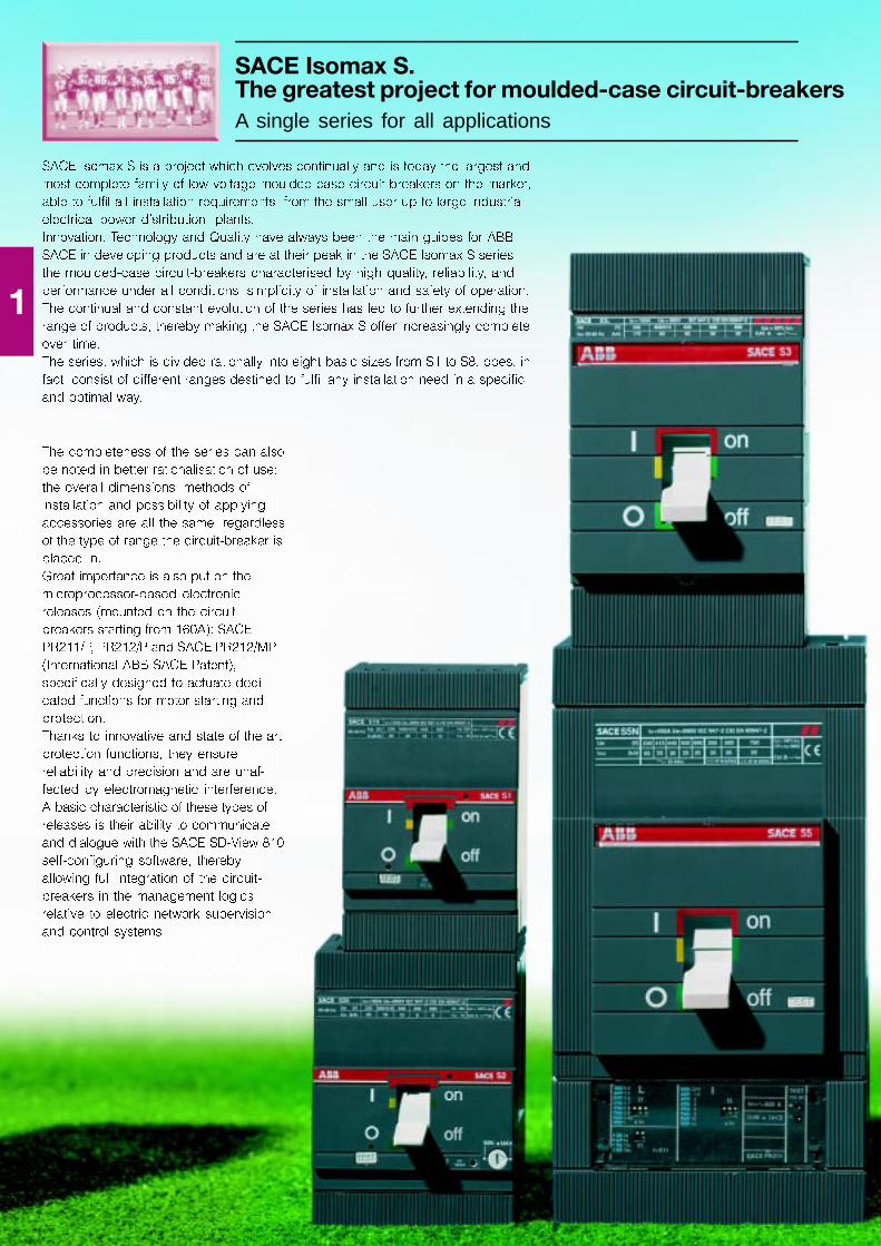
SACE Isomax S.The greatest project for moulded-case circuit-breakersA single series for all applications
SACE Isomax S is a project which evolves continually and is today the largest and
most complete family of low voltage moulded-case circuit-breakers on the market,
able to fulfil all installation requirements, from the small user up to large industrial
electrical power distribution plants.
Innovation, Technology and Quality have always been the main guides for ABB
SACE in developing products and are at their peak in the SACE Isomax S series �
the moulded-case circuit-breakers characterised by high quality, reliability, and
performance under all conditions, simplicity of installation and safety of operation.
The continual and constant evolution of the series has led to further extending the
range of products, thereby making the SACE Isomax S offer increasingly complete
over time.
The series, which is divided rationally into eight basic sizes from S1 to S8, does, in
fact, consist of different ranges destined to fulfil any installation need in a specific
and optimal way.
The completeness of the series can also
be noted in better rationalisation of use:
the overall dimensions, methods of
installation and possibility of applying
accessories are all the same, regardless
of the type of range the circuit-breaker is
placed in.
Great importance is also put on the
microprocessor-based electronic
releases (mounted on the circuit-
breakers starting from 160A): SACE
PR211/P, PR212/P and SACE PR212/MP
(International ABB SACE Patent),
specifically designed to actuate dedi-
cated functions for motor starting and
protection.
Thanks to innovative and state-of-the-art
protection functions, they ensure
reliability and precision and are unaf-
fected by electromagnetic interference.
A basic characteristic of these types of
releases is their ability to communicate
and dialogue with the SACE SD-View 810
self-configuring software, thereby
allowing full integration of the circuit-
breakers in the management logics
relative to electric network supervision
and control systems.
1/3ABB SACE
11
GS
IS90
71
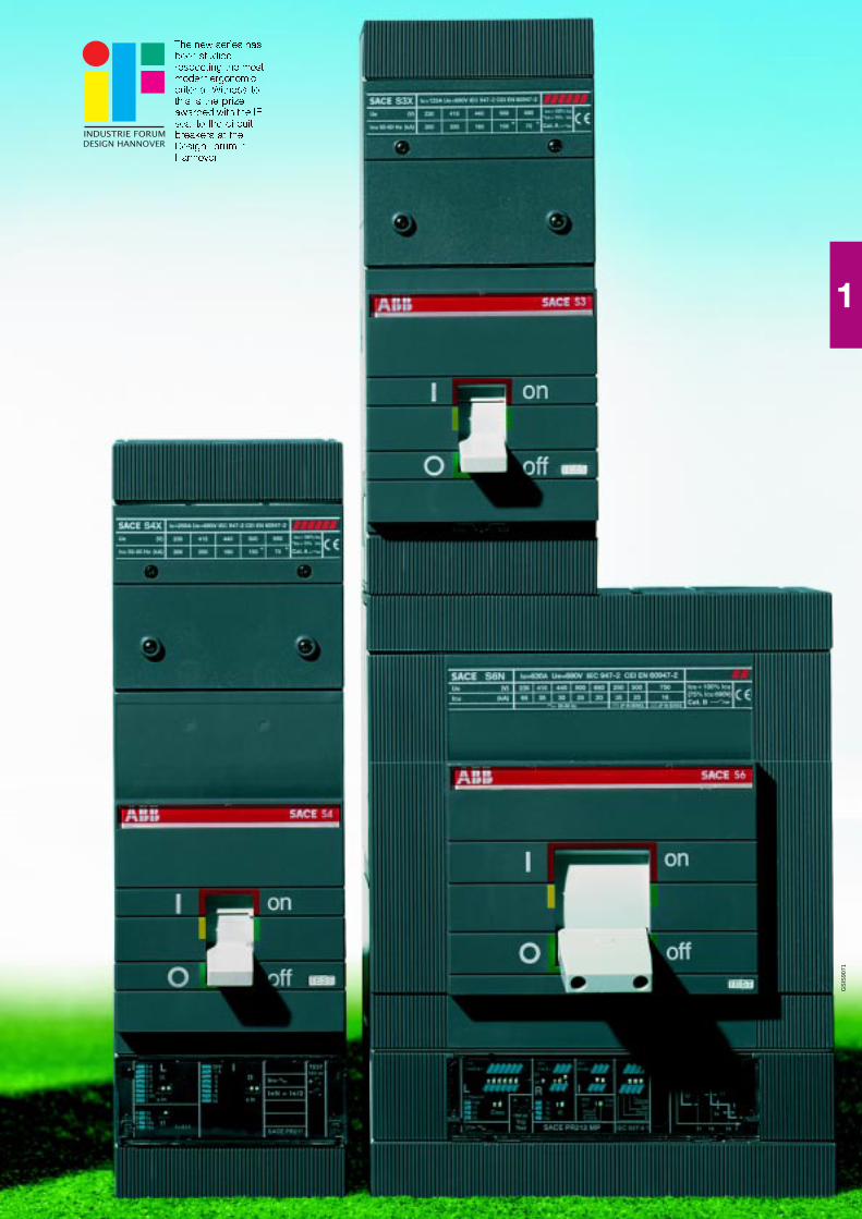
The new series hasbeen studiedrespecting the mostmodern ergonomiccriteria. Witness tothis is the prizeawarded with the IFseal to the circuit-breakers at theDesign Forum inHannover.
1/4 ABB SACE
1
GS
IS90
72G
SIS
9073
GS
IS90
74V~V~V~V~V~V~V~V~V~V~ V–V–V–V–V–V–V–V–V–V–
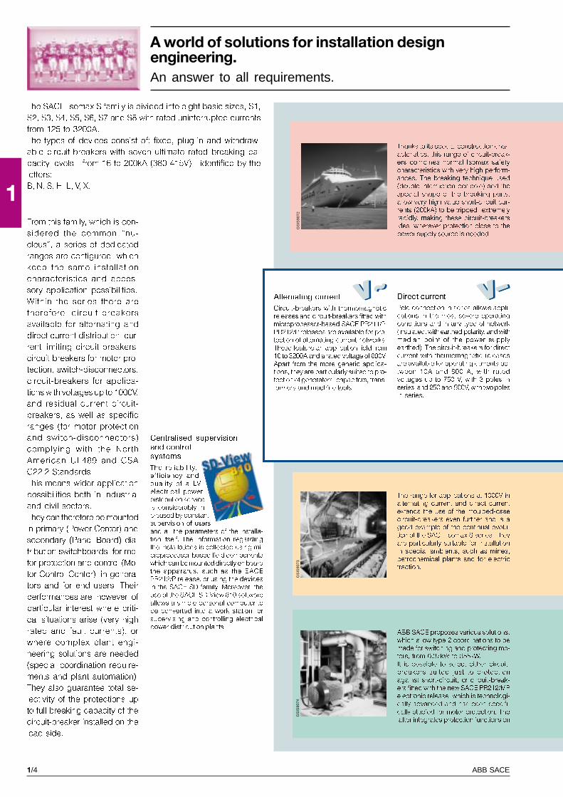
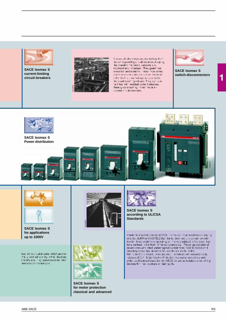
A world of solutions for installation designengineering.An answer to all requirements.
The SACE Isomax S family is divided into eight basic sizes, S1,
S2, S3, S4, S5, S6, S7 and S8 with rated uninterrupted currents
from 125 to 3200A.
The types of devices consist of: fixed, plug-in and withdraw-
able circuit-breakers with seven ultimate rated breaking ca-
pacity levels - from 16 to 200kA (380-415V) - identified by the
letters:
B, N, S, H, L, V, X.
From this family, which is con-
sidered the common �nu-
cleus�, a series of dedicated
ranges are configured, which
keep the same installation
characteristics and acces-
sory application possibilities.
Within the series there are
therefore circuit-breakers
available for alternating and
direct current distribution, cur-
rent-limiting circuit-breakers,
circuit-breakers for motor pro-
tection, switch-disconnectors,
circuit-breakers for applica-
tions with voltages up to 1000V,
and residual current circuit-
breakers, as well as specific
ranges (for motor protection
and switch-disconnectors)
complying with the North
American UL489 and CSA
C22.2 Standards.
This means wider application
possibilities both in industrial
and civil sectors.
They can therefore be mounted
in primary (Power Center) and
secondary (Panel Board) dis-
tribution switchboards, for mo-
tor protection and control (Mo-
tor Control Center), in genera-
tors and for end users. Their
performances are, however, of
particular interest where criti-
cal situations arise (very high
rated and fault currents), or
where complex plant engi-
neering solutions are needed
(special coordination require-
ments and plant automation).
They also guarantee total se-
lectivity of the protections up
to full breaking capacity of the
circuit-breaker installed on the
load side.
Centralised supervisionand controlsystems
The reliability,
efficiency and
quality of a LV
electrical power
distribution service
is considerably in-
creased by constant
supervision of users
and all the parameters of the installa-
tion itself. The information regarding
the installations is collected using mi-
croprocessor-based field components
which can be mounted directly on board
the apparatus, such as the SACE
PR212/P release, or using the devices
in the SACE SD family. Moreover, the
use of the SACE SD-View 810 software
allows a simple personal computer to
be converted into a work station for
supervising and controlling electrical
power distribution plants.ABB SACE proposes various solutions,
which allow type 2 coordinations to be
made for switching and protecting mo-
tors, from 0.37kW to 355kW.
It is possible to select either circuit-
breakers suited just to protection
against short-circuit, or circuit-break-
ers fitted with the new SACE PR212/MP
electronic release, which is technologi-
cally advanced and has been specifi-
cally studied for motor protection. The
latter integrates protection functions on
Alternating current
Circuit-breakers with thermomagnetic
releases and circuit-breakers fitted with
microprocessor-based SACE PR211/P,
PR212/P releases are available for pro-
tection of alternating current networks.
These feature an application field from
10 to 3200A and a rated voltage of 690V.
Apart from the more generic applica-
tions, they are particularly suited to pro-
tection of generators, capacitors, trans-
formers and machine tools.
Direct current
Pole connection in series allows appli-
cations in the most severe operating
conditions and in any type of network
(insulated, with earthed polarity, and with
median point of the power supply
earthed). The circuit-breakers for direct
current with thermomagnetic releases
are available for operating currents be-
tween 10A and 800 A, with rated
voltages up to 750 V, with 3 poles in
series, and 250 and 500V, with two poles
in series.
Thanks to its special construction char-
acteristics, this range of circuit-break-
ers combines normal Isomax safety
characteristics with very high perform-
ances. The breaking technique used
(double interruption per pole) and the
special shape of the breaking parts,
allow very high value short-circuit cur-
rents (200kA) to be tripped extremely
rapidly, making these circuit-breakers
ideal wherever protection close to the
power supply source is needed.
The range for applications at 1000V in
alternating current and direct current
extends the use of the moulded-case
circuit-breakers even further and is a
good example of the continual evolu-
tion of the SACE Isomax S series. They
are particularly suitable for installation
in special ambients, such as mines,
petrochemical plants and for electric
traction.
1/5ABB SACE
1
GS
IS90
75
GS
IS90
93
GS
IS90
91
SACE Isomax Scurrent-limitingcircuit-breakers
SACE Isomax Saccording to UL/CSAStandards
SACE Isomax Sfor motor protectionclassical and advanced
SACE Isomax SPower distribution
SACE Isomax Sfor applicationsup to 1000V
Thanks to a specific range of SACE Isomax S circuit-breakers complying
with the UL489 and CSA22.2 Standards, there are also greater possibili-
ties for those customers operating on markets subject to the specifica-
tions defined in the North American standards. The range consists of
seven sizes with rated uninterrupted current from 100A to 2500A and
breaking capacities, at 480 V AC, which can reach 100kA.
Within the basic series, there are circuit-breakers with magnetic only
releases (MCP - Motor Control Protection) for motor protection, and
switches (Moulded-Case Switch - MCS) for use as isolators or switching
devices for lines, busbars or plant parts.
The switch-disconnectors are derived from
the corresponding circuit-breakers, keeping
the overall dimensions, versions and
accessories unchanged. They guarantee
operation and isolation in maximum safety
and their release device can be activated
either by the undervoltage release or by
the shunt opening release. They can also
be fitted with residual current releases,
thereby constructing �pure� residual-
current circuit-breakers.
SACE Isomax Sswitch-disconnectors 1
board the circuit-breaker which are nor-
mally carried out by other devices,
thereby ensuring numerous installation
and service advantages.
1/6 ABB SACE
1
A world of success
The SACE Isomax S offer has been constantly renewed according to market
requirements � and often even anticipating these � and is always to the fore from
the technological viewpoint. Meanwhile, the quality and reliability have always
remained at the maximum levels expected and the market has shown its apprecia-
tion of this.
Behind every reference lies a require-
ment fulfilled. It is facts which speak for
SACE Isomax S. SACE Isomax S is a
highly successful product of recog-
nised quality, with many fields of
application and it involves different
sectors all over the world, with either
standard or highly personalised
products. There is nowhere electrical
power is used where SACE Isomax S is
not to be found: manufacturing indus-
tries, steelworks, refineries and
chemical plants, drilling rigs, gas
pipelines, water pipelines, hospitals,
airports, trains, railway and under-
ground railway stations, calculation
centres, offices, congress centres,
theatres, and skyscrapers, as well as
the most prestigious buildings world-
wide.
ABB SACE has, moreover, acquired
knowledge which is practically
unsurpassed in application areas
where the highest degree of safety is
required, and this has qualified it as
the world leader in various sectors.
Thousands of ships of all types �
cruise ships, container ships, bulk
carriers, tankers, etc. � and flying the
flags of all nations � are equipped with
ABB SACE products, which are also
widely used in railway traction and are
the favourite product in the depths of
mines.
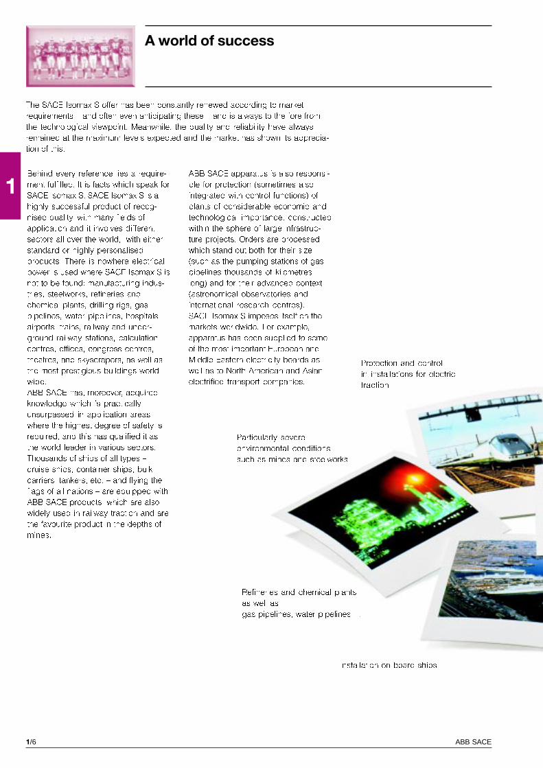
ABB SACE apparatus is also responsi-
ble for protection (sometimes also
integrated with control functions) of
plants of considerable economic and
technological importance, constructed
within the sphere of large infrastruc-
ture projects. Orders are processed
which stand out both for their size
(such as the pumping stations of gas
pipelines thousands of kilometres
long) and for their advanced context
(astronomical observatories and
international research centres).
SACE Isomax S imposes itself on the
markets worldwide. For example,
apparatus has been supplied to some
of the most important European and
Middle Eastern electricity boards as
well as to North American and Asian
electrified transport companies.
Protection and control
in installations for electric
traction
Installation on board ships
Refineries and chemical plants
as well as
gas pipelines, water pipelines �
Particularly severe
environmental conditions
such as mines and steelworks
1/7ABB SACE
11
GS
IS90
76
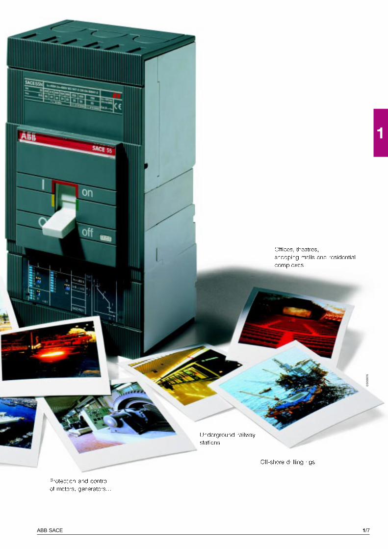
Off-shore drilling rigs
Offices, theatres,
shopping malls and residential
complexes
Protection and control
of motors, generators�
Underground railway
stations
1/8 ABB SACE
1
Selection and design engineering tools,management flexibility, services and consultancy:an all-round offer
With the aim of guiding and facilitating selection of its products, ABB SACE
ensures 360° support, both before and after the sale. For this purpose, to design
and size electrical installations, it makes various work tools available, which
facilitate calculations, ensure compliance of the installation with the Standards
and reduce the risks of any errors.
These are basically divided into calculation, design and estimate software, and
manual tools.
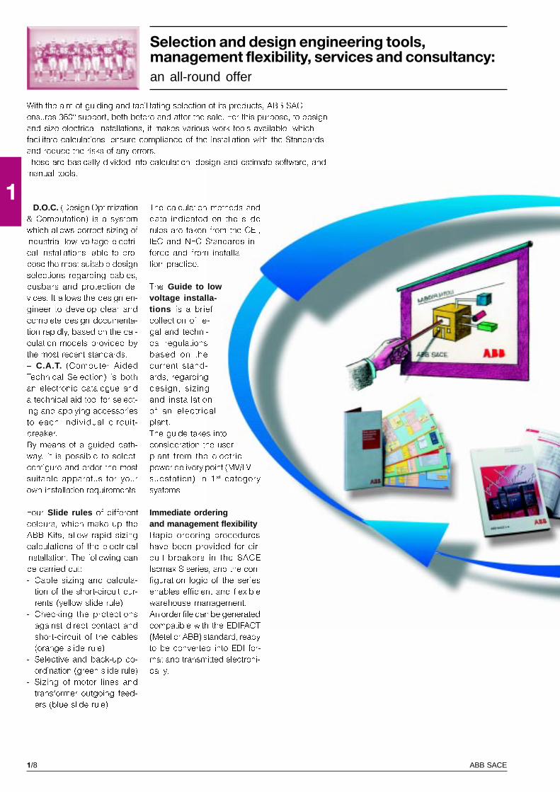
� D.O.C. (Design Optimization
& Computation) is a system
which allows correct sizing of
industrial low voltage electri-
cal installations, able to pro-
pose the most suitable design
selections regarding cables,
busbars and protection de-
vices. It allows the design en-
gineer to develop clear and
complete design documenta-
tion rapidly, based on the cal-
culation models provided by
the most recent standards.
� C.A.T. (Computer Aided
Technical Selection) is both
an electronic catalogue and
a technical aid tool for select-
ing and applying accessories
to each individual circuit-
breaker.
By means of a guided path-
way, it is possible to select,
configure and order the most
suitable apparatus for your
own installation requirements.
Four Slide rules of different
colours, which make up the
ABB Kits, allow rapid sizing
calculations of the electrical
installation. The following can
be carried out:
- Cable sizing and calcula-
tion of the short-circuit cur-
rents (yellow slide rule)
- Checking the protections
against direct contact and
short-circuit of the cables
(orange slide rule)
- Selective and back-up co-
ordination (green slide rule)
- Sizing of motor lines and
transformer outgoing feed-
ers (blue slide rule)
The calculation methods and
data indicated on the slide
rules are taken from the CEI,
IEC and NFC Standards in
force and from installa-
tion practice.
The Guide to lowvoltage installa-tions is a brief
collection of le-
gal and techni-
cal regulations
based on the
current stand-
ards, regarding
design, sizing
and installation
of an electrical
plant.
The guide takes into
consideration the user
plant from the electric
power delivery point (MV/LV
substation) in 1 st category
systems.
Immediate orderingand management flexibilityRapid ordering procedures
have been provided for cir-
cuit-breakers in the SACE
Isomax S series, and the con-
figuration logic of the series
enables efficient and flexible
warehouse management.
An order file can be generated
compatible with the EDIFACT
(Metel or ABB) standard, ready
to be converted into EDI for-
mat and transmitted electroni-
cally.

1/9ABB SACE
1Using EDI (Electronic Data In-
terchange) to send orders ra-
tionalises the logistics chain,
thereby reducing transit times
and the risk of errors. EDI
transmission allows the order
to be loaded automatically at
ABB SACE so that the request
is immediately sent to pro-
duction, together with the
order acknowledge-
ment to the customer.
The availability of
standardised ac-
cessories for
groups of cir-
cuit-breakers
makes it pos-
sible to re-
duce the
number kept
in the ware-
house and
very short
procurement
times allow
limited stocks
to be kept as
these can be
rapidly replen-
ished.
Training:an indispensable toolfor professionalsBy means of its technical train-
ing courses, ABB SACE is
committed to putting its wealth
of experience gained in over
more than 60 years of opera-
tion at disposal. The courses
are an opportunity for all op-
erators in the sector to update
their knowledge and compare
notes, under the guidance of
experts. Information and train-
ing have always been suc-
cess factors for professional
growth and development.
Professional refresher training
on both technical aspects and
product developments, as well
as on the standards and leg-
islation, is essential, consid-
ering that these have such im-
portant implications for the
safety of people and plants.
The primary aim is to meet the
information needs of profes-
sionals, especially by convert-
ing the technical-standard
and legislative concepts into
practical terms which can be
applied directly to the various
products and installations.
“ABB SACE Service”Training courses are also pro-
vided for operators and main-
tenance personnel who work
on ABB SACE apparatus and
systems. For this purpose and
to meet the need for evalua-
tion and maintenance of ex-
isting electrical installations,
the company has set up the
�Service Division� within its
own structure, which acts as
a qualified interlocutor work-
ing in close collaboration with
the managers/users of the
plants, to carry out mainte-
nance, repair and overhauling
activities at ABB SACE and on
the user�s premises. The divi-
sion also offers a spare parts,
assembly and commissioning
service for its own switch-
boards.
1/10 ABB SACE
1
GS
IS90
92
GS
IS90
90
GS
IS90
79
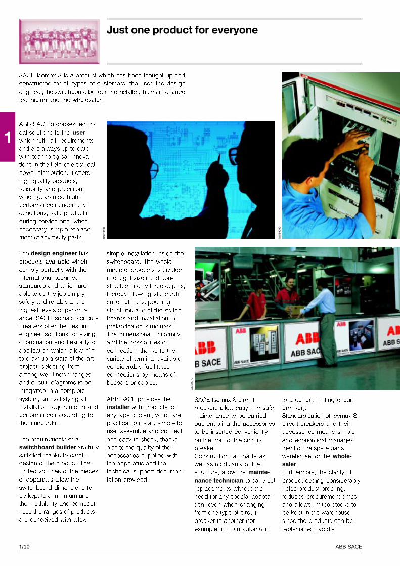
SACE Isomax S is a product which has been thought up and
constructed for all types of customers: the user, the design
engineer, the switchboard builder, the installer, the maintenance
technician and the wholesaler.
ABB SACE proposes techni-
cal solutions to the userwhich fulfil all requirements
and are always up to date
with technological innova-
tions in the field of electrical
power distribution. It offers
high quality products,
reliability and precision,
which guarantee high
performances under any
conditions, safe products
during service and, when
necessary, simple replace-
ment of any faulty parts.
The design engineer has
products available which
comply perfectly with the
international technical
standards and which are
able to do the job simply,
safely and reliably at the
highest levels of perform-
ance. SACE Isomax S circuit-
breakers offer the design
engineer solutions for sizing,
coordination and flexibility of
application which allow him
to draw up a state-of-the-art
project, selecting from
among well-known ranges
and circuit diagrams to be
integrated in a complete
system, and satisfying all
installation requirements and
performances according to
the standards.
The requirements of a
switchboard builder are fully
satisfied thanks to careful
design of the product. The
limited volumes of the pieces
of apparatus allow the
switchboard dimensions to
be kept to a minimum and
the modularity and compact-
ness the ranges of products
are conceived with allow
Just one product for everyone
simple installation inside the
switchboard. The whole
range of products is divided
into eight sizes and con-
structed in only three depths,
thereby allowing standardi-
sation of the supporting
structures and of the switch-
boards and installation in
prefabricated structures.
The dimensional uniformity
and the possibilities of
connection, thanks to the
variety of terminal available,
considerably facilitates
connections by means of
busbars or cables.
ABB SACE provides the
installer with products for
any type of plant, which are
practical to install, simple to
use, assemble and connect
and easy to check, thanks
also to the quality of the
accessories supplied with
the apparatus and the
technical support documen-
tation provided.
to a current-limiting circuit-
breaker).
Standardisation of Isomax S
circuit-breakers and their
accessories means simple
and economical manage-
ment of the spare parts
warehouse for the whole-saler .
Furthermore, the clarity of
product coding considerably
helps product ordering,
reduces procurement times
and allows limited stocks to
be kept in the warehouse
since the products can be
replenished rapidly.
SACE Isomax S circuit-
breakers allow easy and safe
maintenance to be carried
out, enabling the accessories
to be inserted conveniently
on the front of the circuit-
breaker.
Construction rationality as
well as modularity of the
structure, allow the mainte-nance technician to carry out
replacements without the
need for any special adapta-
tion, even when changing
from one type of circuit-
breaker to another (for
example from an automatic
2/1ABB SACE
2
Main characteristics
Index
Panorama of the SACE Isomax S familyPanorama of the SACE Isomax S familyPanorama of the SACE Isomax S familyPanorama of the SACE Isomax S familyPanorama of the SACE Isomax S family
A single series for all applications ...................................................................................... 2/2
Construction characteristicsConstruction characteristicsConstruction characteristicsConstruction characteristicsConstruction characteristics
Distinctive features of the series ........................................................................................ 2/4
Conditions of use ................................................................................................................ 2/8
Modularity of the series SACE Isomax S ........................................................................... 2/10
Compliance with the StandardsCompliance with the StandardsCompliance with the StandardsCompliance with the StandardsCompliance with the Standards
Standards, Approvals, Certifications and company quality system ................................. 2/12
2/2 ABB SACE
2
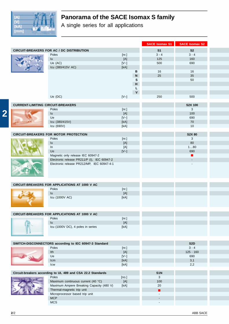
Panorama of the SACE Isomax S familyA single series for all applications
SACE Isomax S1 SACE Isomax S2
CIRCUIT-BREAKERS FOR AC / DC DISTRIBUTION S1 S2Poles [nr.] 3 - 4 3 - 4Iu [A] 125 160Ue (AC) [V~] 500 690Icu (380/415V AC) [kA]
B 16 16N 25 35S 50HLV
Ue (DC) [V–] 250 500
CURRENT-LIMITING CIRCUIT-BREAKERS S2X 100Poles [nr.] 3Iu [A] 100Ue [V~] 690Icu (380/415V) [kA] 70Icu (690V) [kA] 10
CIRCUIT-BREAKERS FOR MOTOR PROTECTION S2X 80Poles [nr.] 3Iu [A] 80In [A] 1…80Ue [V~] 690Magnetic only release IEC 60947-2Electronic release PR211/P (I), IEC 60947-2 -Electronic release PR212/MP, IEC 60947-4-1 -
CIRCUIT-BREAKERS FOR APPLICATIONS AT 1000 V ACPoles [nr.]Iu [A]Icu (1000V AC) [kA]
CIRCUIT-BREAKERS FOR APPLICATIONS AT 1000 V ACPoles [nr.]Iu [A]Icu (1000V DC), 4 poles in series [kA]
SWITCH-DISCONNECTORS according to IEC 60947-3 Standard S2DPoles [nr.] 3 - 4Ith [A] 125 - 160Ue [V~] 690Icm [kA] 3,1Icw [kA] 2,2
Circuit-breakers according to UL 489 and CSA 22.2 Standards S1NPoles [no.] 3Maximum continuous current (40 °C) [A] 100Maximum Ampere Breaking Capacity (480 V) [kA] 20Thermal-magnetic trip unitMicroprocessor based trip unit -MCP -MCS -
2/3ABB SACE
2
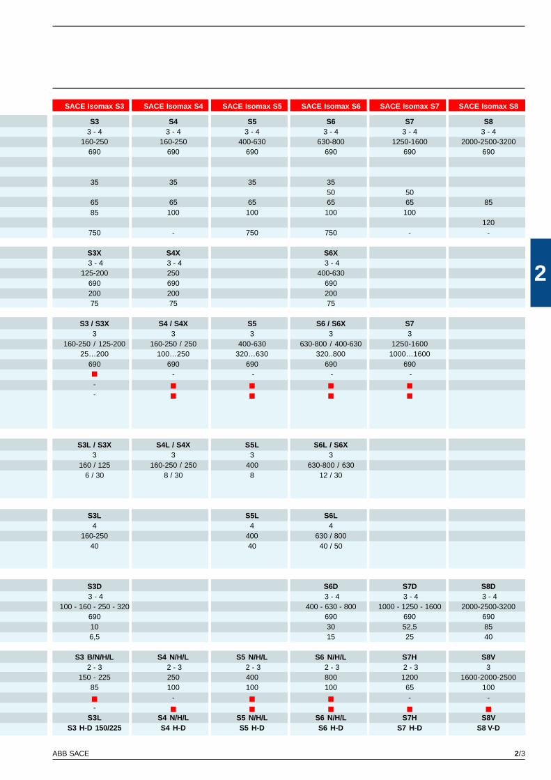
SACE Isomax S3 SACE Isomax S4 SACE Isomax S5 SACE Isomax S6 SACE Isomax S7 SACE Isomax S8
S3 S4 S5 S6 S7 S83 - 4 3 - 4 3 - 4 3 - 4 3 - 4 3 - 4
160-250 160-250 400-630 630-800 1250-1600 2000-2500-3200690 690 690 690 690 690
35 35 35 3550 50
65 65 65 65 65 8585 100 100 100 100
120750 - 750 750 - -
S3X S4X S6X 3 - 4 3 - 4 3 - 4
125-200 250 400-630690 690 690200 200 20075 75 75
S3 / S3X S4 / S4X S5 S6 / S6X S73 3 3 3 3
160-250 / 125-200 160-250 / 250 400-630 630-800 / 400-630 1250-160025…200 100…250 320…630 320..800 1000…1600
690 690 690 690 690- - - -
--
S3L / S3X S4L / S4X S5L S6L / S6X3 3 3 3
160 / 125 160-250 / 250 400 630-800 / 6306 / 30 8 / 30 8 12 / 30
S3L S5L S6L4 4 4
160-250 400 630 / 80040 40 40 / 50
S3D S6D S7D S8D 3 - 4 3 - 4 3 - 4 3 - 4
100 - 160 - 250 - 320 400 - 630 - 800 1000 - 1250 - 1600 2000-2500-3200690 690 690 69010 30 52,5 856,5 15 25 40
S3 B/N/H/L S4 N/H/L S5 N/H/L S6 N/H/L S7H S8V2 - 3 2 - 3 2 - 3 2 - 3 2 - 3 3
150 - 225 250 400 800 1200 1600-2000-250085 100 100 100 65 100
- - --
S3L S4 N/H/L S5 N/H/L S6 N/H/L S7H S8VS3 H-D 150/225 S4 H-D S5 H-D S6 H-D S7 H-D S8 V-D
2/4 ABB SACE
2
GS
IS90
69
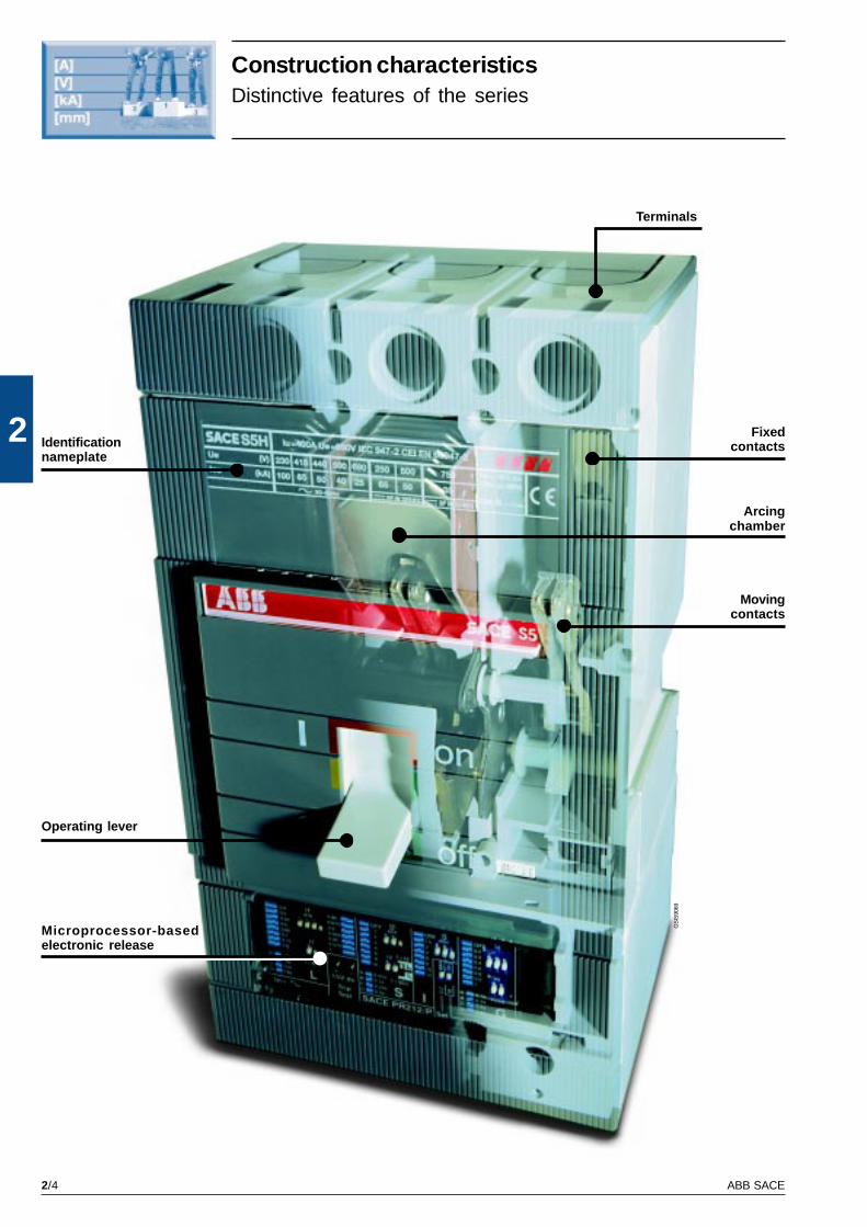
Construction characteristicsDistinctive features of the series
Terminals
Fixedcontacts
Arcingchamber
Movingcontacts
Microprocessor-basedelectronic release
Operating lever
Identificationnameplate
2/5ABB SACE
2G
SIS
9048
GS
IS90
51
GS
IS00
74
GS
IS90
50
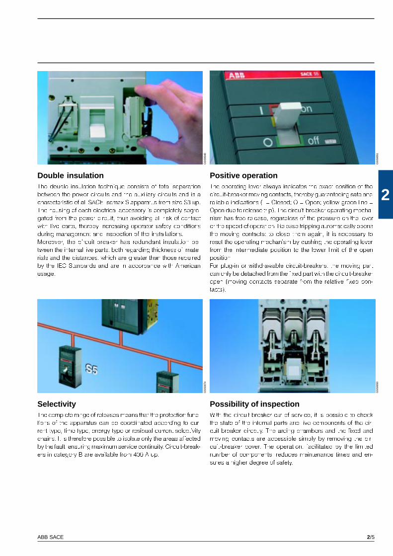
SelectivityThe complete range of releases means that the protection func-
tions of the apparatus can be coordinated according to cur-
rent-type, time-type, energy-type or residual-current selectivity
chains. It is therefore possible to isolate only the areas affected
by the fault, ensuring maximum service continuity. Circuit-break-
ers in category B are available from 400 A up.
Possibility of inspectionWith the circuit-breaker out of service, it is possible to check
the state of the internal parts and live components of the cir-
cuit-breaker directly. The arcing chambers and the fixed and
moving contacts are accessible simply by removing the cir-
cuit-breaker cover. The operation, facilitated by the limited
number of components, reduces maintenance times and en-
sures a higher degree of safety.
Double insulationThe double insulation technique consists of total separation
between the power circuits and the auxiliary circuits and is a
characteristic of all SACE Isomax S apparatus from size S3 up.
The housing of each electrical accessory is completely segre-
gated from the power circuit, thus avoiding all risk of contact
with live parts, thereby increasing operator safety conditions
during management and inspection of the installations.
Moreover, the circuit-breaker has redundant insulation be-
tween the internal live parts, both regarding thickness of mate-
rials and the distances, which are greater than those required
by the IEC Standards and are in accordance with American
usage.
Positive operationThe operating lever always indicates the exact position of the
circuit-breaker moving contacts, thereby guaranteeing safe and
reliable indications (I = Closed; O = Open; yellow-green line =
Open due to release trip). The circuit-breaker operating mecha-
nism has free release, regardless of the pressure on the lever
or the speed of operation. Release tripping automatically opens
the moving contacts: to close them again, it is necessary to
reset the operating mechanism by pushing the operating lever
from the intermediate position to the lower limit of the open
position.
For plug-in or withdrawable circuit-breakers, the moving part
can only be detached from the fixed part with the circuit-breaker
open (moving contacts separate from the relative fixed con-
tacts).

2/6 ABB SACE
2
GS
IS91
26
GS
IS91
25
GS
IS91
29
GS
IS91
27
Construction characteristicsDistinctive features of the series
TropicalisationThe SACE Isomax S series of circuit-breakers and accessories
comply with the strictest regulations for use in hot-humid-sa-
line climates (in compliance with climatograph 8 of the IEC
721-2-1 Standards), thanks to:
� insulating cases made of fibreglass-reinforced synthetic res-
ins;
� anti-corrosion treatment on all main metal parts (C UNI 3564-
65 environment);
� Fe/Zn 12 galvanisation (UNI ISO 2081), protected by a con-
version layer consisting mainly of chromates (UNI ISO 4520).
Isolation behaviourIn the open position, the circuit-breaker guarantees isolation of
the circuit in compliance with the IEC 60947-2 Standard. For
plug-in or withdrawable version circuit-breakers, in the racked-
out or withdrawn position, the power and auxiliary circuits are
isolated, ensuring that no parts are live. Under these condi-
tions and by means of special connectors, it is possible to
carry out blank tests, operating the circuit-breaker in complete
safety. The redundant insulation distances guarantee the ab-
sence of leakage currents and dielectric strength in the event
of any overvoltages between the input and output.
Electromagnetic compatibilityBy using SACE PR211/P, PR212/P, PR212/MP microprocessor-
based overcurrent releases and SACE RC210, RC211, RC212
electronic residual-current releases, the absence of unwar-
ranted trips is guaranteed even in the presence of interference
caused by electronic equipment, atmospheric disturbance or
discharges of electrical type. Furthermore, the apparatus does
not generate interference with other electronic equipment in
the vicinity of the installation. This is in compliance with the IEC
60947-2 Appendix F, IEC 1000-4, EN 61000-4, EN 50081-1, EN
50081-2, EN 50082-1, EN 50082-2 European Directive No. 89/
336 specifications regarding electromagnetic compatibility
EMC.
Racking-out with the door closedThis system, starting from 160 A, allows the circuit-breaker to
be racked in and out with the compartment door closed, in-
creasing operator safety and allowing construction of internal
arc proof low voltage switchboards. Racking out can only take
place with the circuit-breaker open, using a special racking-
out crank handle supplied with the withdrawable version cir-
cuit-breaker.
2/7ABB SACE
2G
SIS
9131
GS
IS91
28
GS
IS91
30G
SIS
9062
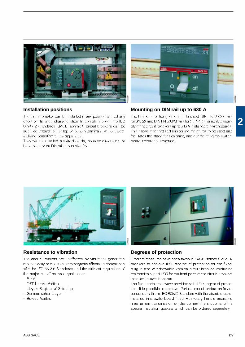
Mounting on DIN rail up to 630 AThe brackets for fixing onto standardised DIN EN 50022 rails
for S1, S2 and DIN EN 50023 rails for S3, S4, S5 simplify assem-
bly of the circuit-breakers up to 630 A in standard switchboards.
This allows standardised supporting structures to be used and
facilitates the stage for designing and constructing the switch-
board metalwork structure.
Resistance to vibrationThe circuit-breakers are unaffected by vibrations generated
mechanically or due to electromagnetic effects, in compliance
with the IEC 68-2-6 Standards and the strictest regulations of
the major classification organisations:
� RINA
� DET Norske Veritas
� Lloyd�s Register of Shipping
� Germanischer Lloyd
� Bureau Veritas.
Degrees of protectionDifferent measures have been taken in SACE Isomax S circuit-
breakers to achieve IP20 degree of protection for the fixed,
plug-in and withdrawable version circuit-breaker, excluding
the terminals, and IP30 for the front parts of the circuit-breakers
installed in switchboards.
The fixed parts are always provided with IP20 degree of protec-
tion. It is possible to achieve IP54 degree of protection in ac-
cordance with the IEC 60529 Standard with the circuit-breaker
installed in a switchboard fitted with rotary handle operating
mechanism transmission on the compartment door and the
special insulation gaskets which can be ordered separately.
Installation positionsThe circuit-breaker can be installed in any position without any
effect on its rated characteristics. In compliance with the IEC
60947-2 Standards, SACE Isomax S circuit-breakers can be
supplied through either top or bottom terminals, without jeop-
ardising operation of the apparatus.
They can be installed in switchboards, mounted directly on the
base plate or on Din rails up to size S5.
2/8 ABB SACE
2 GS
IS90
80
GS
IS90
81
GS
IS90
83G
SIS
9086
GS
IS90
84
GS
IS90
85G
SIS
9082
GS
IS90
87
GS
IS90
88
IP20 IP30
IP30
IP40 (1)
IP50
IP30
IP40IP54
IP30 (2)
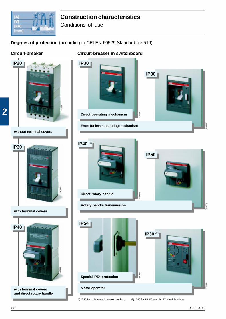
Construction characteristicsConditions of use
Degrees of protection (according to CEI EN 60529 Standard file 519)
Circuit-breaker Circuit-breaker in switchboard
without terminal covers
with terminal coversand direct rotary handle
with terminal covers
Special IP54 protection
Motor operator
Rotary handle transmission
Front for lever operating mechanism
Direct operating mechanism
Direct rotary handle
(1) IP30 for withdrawable circuit-breakers (2) IP40 for S1-S2 and S6-S7 circuit-breakers
2/9ABB SACE
2
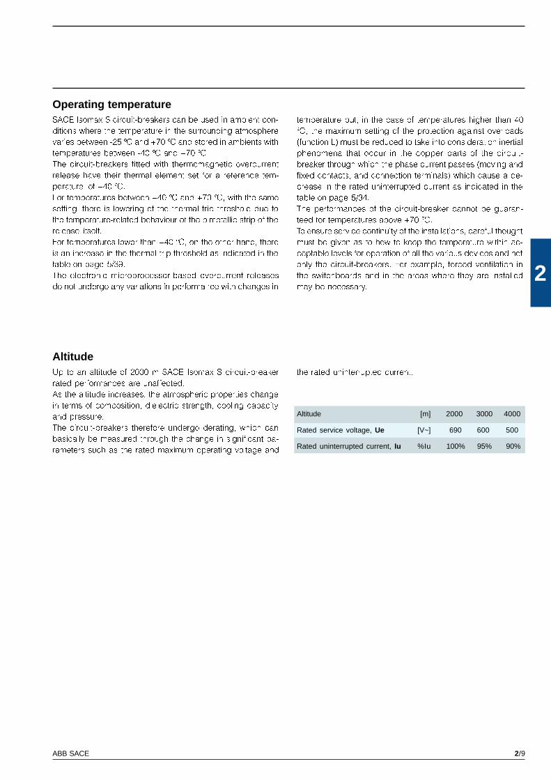
Operating temperatureSACE Isomax S circuit-breakers can be used in ambient con-
ditions where the temperature in the surrounding atmosphere
varies between -25 °C and +70 °C and stored in ambients with
temperatures between -40 °C and +70 °C.
The circuit-breakers fitted with thermomagnetic overcurrent
release have their thermal element set for a reference tem-
perature of +40 °C.
For temperatures between +40 °C and +70 °C, with the same
setting, there is lowering of the thermal trip threshold due to
the temperature-related behaviour of the bimetallic strip of the
release itself.
For temperatures lower than +40 °C, on the other hand, there
is an increase in the thermal trip threshold as indicated in the
table on page 5/39.
The electronic microprocessor-based overcurrent releases
do not undergo any variations in performance with changes in
Altitude [m] 2000 3000 4000
Rated service voltage, Ue [V~] 690 600 500
Rated uninterrupted current, Iu %Iu 100% 95% 90%
the rated uninterrupted current.Up to an altitude of 2000 m SACE Isomax S circuit-breaker
rated performances are unaffected.
As the altitude increases, the atmospheric properties change
in terms of composition, dielectric strength, cooling capacity
and pressure.
The circuit-breakers therefore undergo derating, which can
basically be measured through the change in significant pa-
rameters such as the rated maximum operating voltage and
temperature but, in the case of temperatures higher than 40
°C, the maximum setting of the protection against overloads
(function L) must be reduced to take into consideration inertial
phenomena that occur in the copper parts of the circuit-
breaker through which the phase current passes (moving and
fixed contacts, and connection terminals) which cause a de-
crease in the rated uninterrupted current as indicated in the
table on page 5/34.
The performances of the circuit-breaker cannot be guaran-
teed for temperatures above +70 °C.
To ensure service continuity of the installations, careful thought
must be given as to how to keep the temperature within ac-
ceptable levels for operation of all the various devices and not
only the circuit-breakers. For example, forced ventilation in
the switchboards and in the areas where they are installed
may be necessary.
Altitude
2/10 ABB SACE
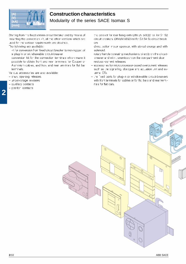
2
Construction characteristicsModularity of the series SACE Isomax S
Starting from the fixed version circuit-breaker and by means of
mounting the conversion kit, all the other versions which are
used for the various requirements are obtained.
The following are available:
� kit for conversion from fixed circuit-breaker to moving part of
a plug-in or withdrawable circuit-breaker
� conversion kit for the connection terminals which make it
possible to obtain front and rear terminals for Copper or
Aluminium cables, and front and rear terminals for flat bar
terminals.
Various accessories are also available:
� shunt opening releases
� undervoltage releases
� auxiliary contacts
� position contacts
� the bracket for rear fixing onto DIN EN 50022 rail for S1-S2
circuit-breakers, DIN EN 50023 rail for S3-S4-S5 circuit-break-
ers
� direct action motor operator, with stored energy and with
solenoid.
� rotary handle operating mechanisms directly on the circuit-
breaker and with transmission on the compartment door
� residual-current releases
� accessories for microprocessor-based overcurrent releases
such as the signalling, dialogue and actuation unit and ex-
ternal CTs.
� the fixed parts for plug-in or withdrawable circuit-breakers
with front terminals for cables or for flat bars and rear termi-
nals for flat bars.

2/11ABB SACE
2
GS
IS01
59

2/12 ABB SACE
2
ISO 9001
GS
IS91
19
GS
IS91
18G
SIS
9119
GS
IS91
32
Compliance with the StandardsStandards, Approvals, Certifications and company qualitysystem
The ABB SACE Quality System complies
with the International ISO 9001 Stand-
ard (model for assuring quality in design,
development, construction, installation
and assistance) and to the equivalent
European EN ISO 9001 and Italian UNI
EN ISO 9001 Standards.
The certification Organisation is RINA-
QUACER.
ABB SACE obtained its first certification
in 1990.
The ABB SACE Test Room is accredited
by SINAL. The apparatus complies with
the prescriptions for on-board installa-
tions and is approved by major Shipping
Registers, such as: LLOYD�S REGISTER
OF SHIPPING, GERMANlSCHER LLOYD,
BUREAU VERITAS, RINA, DET NORSKE
VERITAS, POLSKI REIESTR STATKOW
and the AMERICAN BUREAU OF SHIP-
PING.
SACE Isomax S circuit-breakers and their
accessories comply with the IEC 60947-
2, EN 60947-2 (unified in 17 countries
of CENELEC), CEI EN 60947 and IEC
61000 international Standards and con-
form with the EC directive:
� �Low Voltage Directives� (LVD)
no. 73/23 EEC
� �Electromagnetic Compatibility Direc-
tive� (EMC) no. 89/336 EEC.
Certification of compliance with the
above-mentioned product Standards, is
carried out, in respect of the European
EN 45011 Standard, by the
Italian certification organisa-
tion, ACAE (Association for
Certification of Electrical Ap-
paratus),- member of the Eu-
ropean organisation LOVAG
(Low Voltage Agreement
Group).
ABB SACE was the first industrial com-
pany in the electro-mechanical sector
in Italy to obtain this recognition, and,
thanks to a revision of its production
process with an eye to ecology, has
managed to reduce consumption of raw
materials, processing waste and the risk
of accidents by 20%.
The attention paid to protecting the en-
vironment and to the safety of workers is
a priority commitment of ABB SACE and
as confirmation of this, the company de-
veloped the Environmental Management
System in compliance with the Interna-
tional ISO 14001 Standard, certified in
1997, integrating this in 1999 with the
Health and Safety in the Workplace Man-
agement System in accordance with BS
8800 (British Standards).
The prizes obtained by ABB SACE at the
Forum Design in Hannover and at
Electro in Paris bear witness to the con-
sideration given to man and the respect
for ergonomic criteria.
The attention paid to protecting the en-
vironment is another important priority
for ABB SACE, and as confirmation of
this, the environmental management
system has been certified by RINA.
Please contact ABB SACE for information
regarding the types of circuit-breakers ap-
proved, the performances approved and
their relative validity.
3/1ABB SACE
3
The ranges
Index
SACE Isomax S circuit-breakers for power distribution ........................................... 3/3
Electrical characteristics IEC 60947-2 .............................................................................. 3/4
General characteristics ..................................................................................................... 3/6
Thermomagnetic releases ................................................................................................. 3/8
Electronic releases ............................................................................................................ 3/10
SACE Isomax S current-limiting circuit-breakers ...................................................... 3/15
Electrical characteristics IEC 60947-2 .............................................................................. 3/16
General characteristics ..................................................................................................... 3/18
SACE Isomax S circuit-breakers for motor protection
(protection against short-circuit) .................................................................................. 3/23
Electrical characteristics IEC 60947-4 .............................................................................. 3/24
General characteristics ..................................................................................................... 3/26
SACE Isomax S circuit-breakers for motor protection
(integrated protection) .................................................................................................... 3/28
Electrical characteristics IEC 60947-2 and IEC 60947-4 ................................................. 3/28
General characteristics ..................................................................................................... 3/30
SACE Isomax S circuit-breakers for applications up to 1000V ................................ 3/35
Electrical and general characteristics IEC 60947-2 ......................................................... 3/36
SACE Isomax S switch-disconnectors ........................................................................ 3/39
Electrical and general characteristics IEC 60947-3 ......................................................... 3/40
SACE Isomax S circuit-breakers in accordance with UL489 and CSA C22.2
Standards .......................................................................................................................... 3/43
Electrical and general characteristics ............................................................................... 3/44

3/3
3
GS
IS90
63
Circuit-breakers for powerdistribution
Eight sizes to optimise use for all plant andinstallation requirements
690V • 125-3200 A • 16-120 kA (380/415 V)

3/4 ABB SACE
3
SACE Isomax S3
160 - 250
3-4
690
750
8
800
3000
N H L
65 100 170
35 (1) 65 85
30 50 65
25 40 50
14 18 20 (5)
35 65 85
35 50 65
- - -
20 35 50
100% 75% 75%
74 143 187
8 7 6
A
F - P - W
F- EF - ES - FC
FC CuAl - RC - R
EF - FC - R
EF - FC - R
DIN EN 50023
25000/120
10000(160A)-8000(250A)/120
105/140
103,5
170
2,6 / 3,5
3,1 / 4,1
3,5 / 4,5
SACE Isomax S2
160
3-4
690
500
6
690
3000
B N S
25 50 65
16 35 (1) 50
10 20 25
8 12 15
6 8 10
16 35 50
- - -
16 35 50
- - -
100% 75% 75%
32 74 105
8 7 6
A
F - P
EF - FC - FC CuAl - R
FC - R
-
DIN EN 50022
25000/240
8000/120
90/120
70
120
1,1/1,5
1,3/1,7
-
GS
IS91
33
GS
IS91
34
GS
IS91
35
SACE Isomax S circuit-breakersfor power distributionElectrical characteristics IEC 60947-2
(1) All the versions with Icu=35kA are certified at 36kA
(2) For S3 N/H/L, S4 N/H/L, S5 N/H, and S6 N/S/H circuit-
breakers the performance percentage of Ics at 690V is
reduced by 25%.
(3) The withdrawable version circuit-breakers must be fitted
with the front flange for the lever operating mechanism or
with its alternative accessories, such as the rotary handle
or the motor operator
(4) For the S5 circuit-breaker, the plug-in version is only
available for the version with 400 A rated current
(5) The SACE S3 circuit-breaker with breaking capacity L at
690 V can only be supplied from above
Rated uninterrupted current, Iu [A]
Poles Nr.
Rated service voltage, Ue (AC) 50-60Hz [V]
(DC) [V]
Rated impulse withstand voltage, Uimp [kV]
Rated insulation voltage, Ui [V]
Test voltage at industrial frequency for 1 min. [V]
Rated ultimate short-circuit breaking capacity, Icu
(AC) 50-60 Hz 220/230 V [kA]
(AC) 50-60 Hz 380/415 V [kA]
(AC) 50-60 Hz 440 V [kA]
(AC) 50-60 Hz 500 V [kA]
(AC) 50-60 Hz 690 V [kA]
(DC) 250 V - 2 poles in series [kA]
(DC) 500 V - 2 poles in series [kA]
(DC) 500 V - 3 poles in series [kA]
(DC) 750 V - 3 poles in series [kA]
Rated short-circuit service breaking capacity, Ics (2) [%Icu]
Rated short-circuit making capacity (415 V) [kA]
Opening time (415V at Icu) [ms]
Rated short-time withstand current for 1 s, Icw [kA]
Utilisation category (EN 60947-2)
Isolation behaviour
IEC 60947-2, EN 60947-2
Releases: thermomagnetic T fixed, M fixed 5 Ith
T fixed, M fixed 10 Ith
T adjustable, M fixed 3 Ith
T adjustable, M fixed 5 Ith
T adjustable, M fixed 10 Ith
T adjustable, M adjustable
magnetic only M fixed
with microprocessor PR211/P (I-LI)
PR212/P (LSI-LSIG)
Interchangeability
Versions
Terminals fixed
plug-in
withdrawable (3)
Fixing on DIN rail
Mechanical life [No. operations / hourly operations]
Electrical life (at 415 V) [No. operations / hourly operations]
Basic dimensions, fixed 3/4 poles L [mm]
D [mm]
H [mm]
Weights fixed 3/4 poles [kg]
plug-in 3/4 poles [kg]
withdrawable 3/4 poles [kg]
SACE Isomax S1
125
3-4
500
250
6
500
3000
B N
25 40
16 25
10 16
8 12
- -
16 25
- -
- -
- -
50% 50%
32 52,5
8 6
A
F - P
FC-R
FC-R
-
DIN EN 50022
25000/240
8000/120
78/103
70
120
0,9 /1,2
1 / 1,4
-
3/5ABB SACE
3
SACE Isomax S8
2000 - 2500 - 3200
3-4
690
-
8
690
2500
H V
85 120
85 120
70 100
50 70
40 50
- -
- -
- -
- -
50% 50%
187 264
20 20
35
B
F
F (2000-2500A) - VR
-
-
-
10000/20
2500(2500A)/20-1500(3200A)/10
406/556
242
400
57/76
-
-
SACE Isomax S7
1250 - 1600
3-4
690
-
8
800
3000
S H L
85 100 200
50 65 100
40 55 80
35 45 70
20 25 35
- - -
- - -
- - -
- - -
100% 75% 50%
105 143 220
22 22 22
15 (1250A) - 20 (1600A)
B
F - W
F - EF - ES - FC CuAl (1250A)
HR - VR
-
EF - HR - VR
-
10000/120
7000(1250A)-5000(1600A)/20
210/280
138,5
406
17 / 22
-
21,8 / 29,2
SACE Isomax S4
160 - 250
3-4
690
-
8
800
3000
N H L
65 100 200
35 (1) 65 100
30 50 80
25 40 65
18 22 30
- - -
- - -
- - -
- - -
100% 100% 75%
74 143 220
8 7 6
A
F - P - W
F - EF - ES - FC
FC CuAl - RC - R
EF - FC - R
EF - FC - R
DIN EN 50023
20000/120
10000(160A)-8000(250A)/120
105/140
103,5
254
4 / 5,3
4,5 / 5,9
4,9 / 6,3
SACE Isomax S5
400 - 630
3-4
690
750
8
800
3000
N H L
65 100 200
35 (1) 65 100
30 50 80
25 40 65
20 25 30
35 65 100
35 50 65
- - -
20 35 50
100% 100% 75%
74 143 220
8 7 6
5 (400A)
B (400A) - A (630A)
F - P (400) - W
F - EF(400A) - ES - FC
FC CuAl (400A)-RC (400A)-R
EF - FC - R
EF(400A) - ES - FC (400A)
R - VR (630A)
DIN EN 50023
20000/120
7000(400A)-5000(630A)/60
140/184
103,5
254
5 / 7
6,1 / 8,4
6,4 / 8,7
SACE Isomax S6
630 - 800
3-4
690
750
8
800
3000
N S H L
65 85 100 200
35 (1) 50 65 100
30 45 50 80
25 35 40 65
20 22 25 30
35 50 65 100
20 35 50 65
- - - -
16 20 35 50
100% 100% 100% 75%
74 105 143 220
10 9 8 7
7,6 (630A) - 10 (800A)
B
F - W
F - EF - ES - FC CuAl
RC - R
-
EF - HR - VR
-
20000/120
7000(630A)-5000(800A)/60
210/280
103,5
268
9,5 / 12
-
12,1 / 15,1
GS
IS90
95
GS
IS90
96
GS
IS90
97
GS
IS90
98
GS
IS91
36
KEY TO TERMINALS
F = Front
EF = Extended front
ES = Extended spreaded front
KEY TO VERSIONS
F = Fixed
P = Plug-in
W = Withdrawable
FC = Front for copper cables
FC CuAl = Front for copper or aluminium cables
R = Rear threaded
RC = Rear for copper or aluminium cables
HR = Rear horizontal flat bar
VR = Rear vertical flat bar
3/6 ABB SACE
3
GS
IS00
78
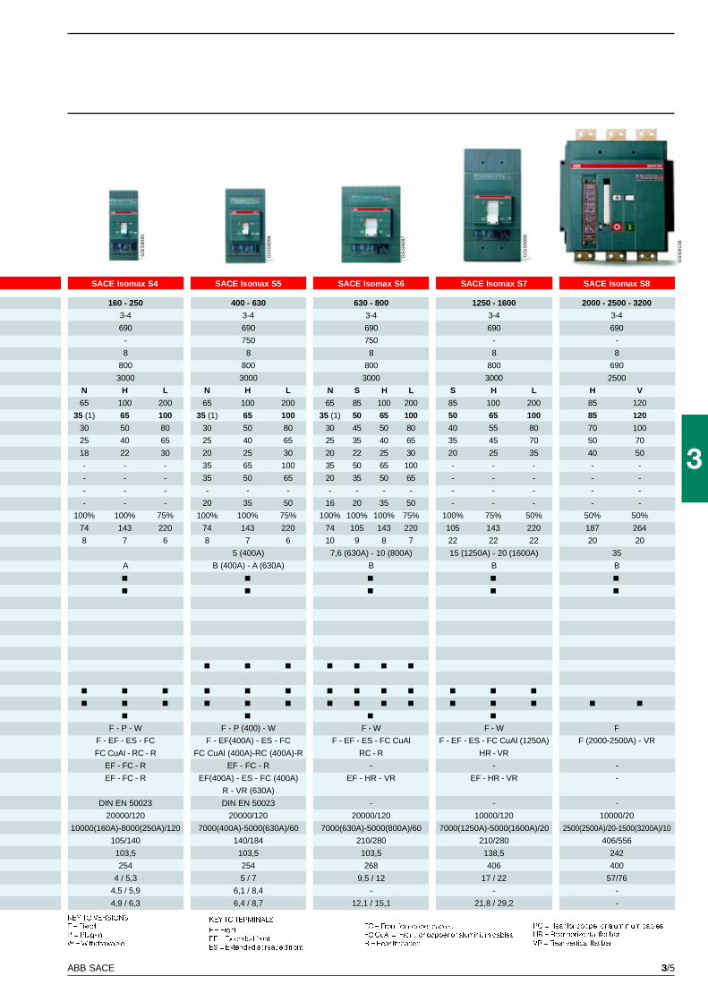
SACE Isomax S circuit-breakersfor power distributionGeneral characteristics
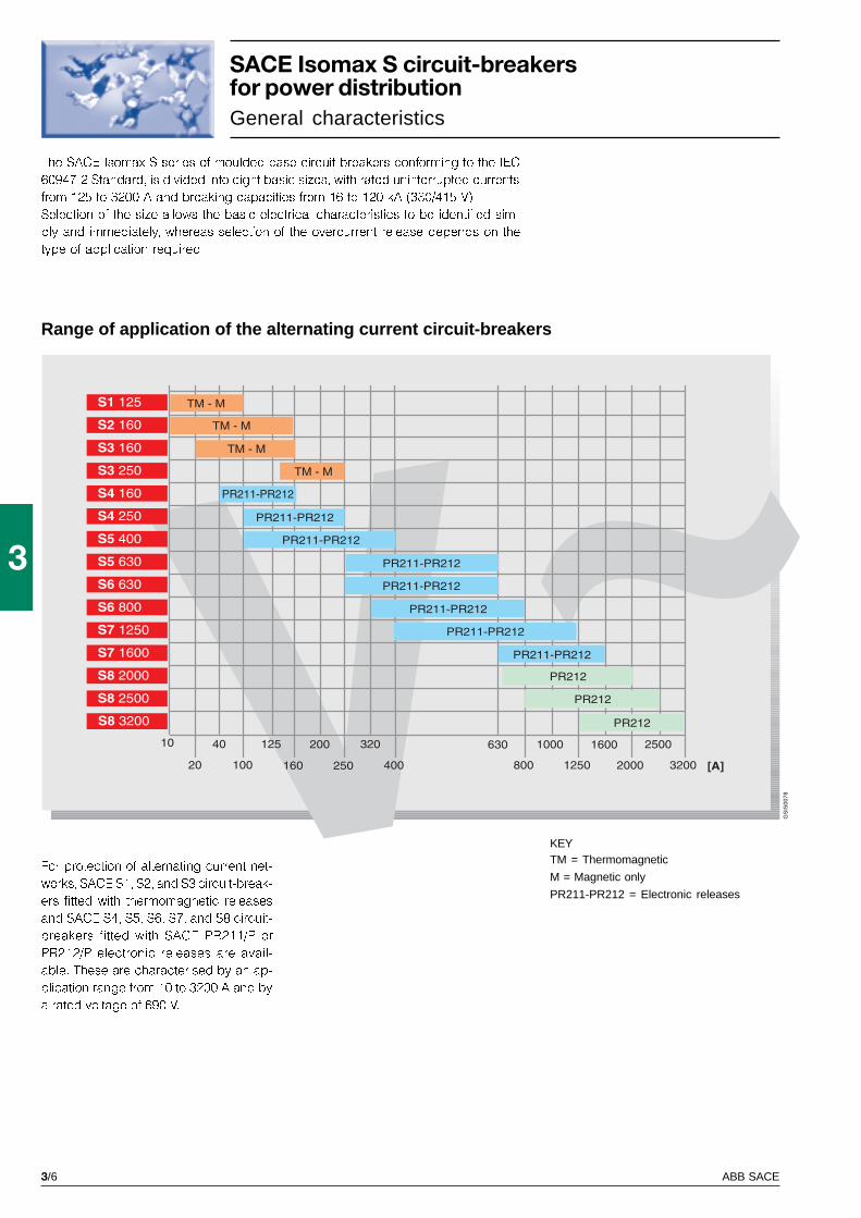
The SACE Isomax S series of moulded-case circuit-breakers conforming to the IEC
60947-2 Standard, is divided into eight basic sizes, with rated uninterrupted currents
from 125 to 3200 A and breaking capacities from 16 to 120 kA (380/415 V).
Selection of the size allows the basic electrical characteristics to be identified sim-
ply and immediately, whereas selection of the overcurrent release depends on the
type of application required.
For protection of alternating current net-
works, SACE S1, S2, and S3 circuit-break-
ers fitted with thermomagnetic releases
and SACE S4, S5, S6, S7, and S8 circuit-
breakers fitted with SACE PR211/P or
PR212/P electronic releases are avail-
able. These are characterised by an ap-
plication range from 10 to 3200 A and by
a rated voltage of 690 V.
Range of application of the alternating current circuit-breakers
KEYTM = Thermomagnetic
M = Magnetic only
PR211-PR212 = Electronic releases
3/7ABB SACE
3
GS
IS00
79
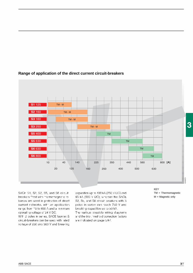
Range of application of the direct current circuit-breakers
KEYTM = Thermomagnetic
M = Magnetic onlySACE S1, S2, S3, S5, and S6 circuit-
breakers fitted with thermomagnetic re-
leases are used in protection of direct
current networks, with an application
range from 10 to 800 A and a minimum
operating voltage of 24 V DC.
With 2 poles in series, SACE Isomax S
circuit-breakers can be used with rated
voltage of 250 and 500 V and breaking
capacities up to 100 kA (250 V DC) and
65 kA (500 V DC); whereas the SACE
S3, S5, and S6 circuit-breakers with 3
poles in series can reach 750 V and
breaking capacities up to 50 kA.
The various possible wiring diagrams
and the trip threshold correction factors
are indicated on page 5/47.

3/8 ABB SACE
3
GS
IS90
58
L1 - L2 - L3 R10 R12,5 R16 R20 R25 R32 R32 R40 R50 R50 R63 R80 R100 R125 R125
R10 R12.5 R16 R20 R25 R32 R32 R40 R50 R50 R63 R80 R100 R125 R80
S1 125
S2 160
S3 160
S3 250
S5 400
S5 630
S6 630
S6 800
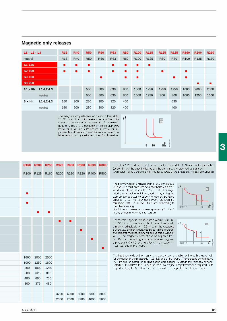
SACE Isomax S circuit-breakersfor power distributionThermomagnetic releases
SACE Isomax S1, S2, S3, S5, and S6 circuit-breakers can be
fitted with thermomagnetic releases and are used for protec-
tion of alternating current networks with the S1, S2, and S3
circuit-breakers (for applications from 10A to 250A) and in
direct current with the S1, S2, S3, S5, and S6 circuit-breakers
(from 10A to 800A). They allow protection against overloads
using a thermal device (with fixed threshold for S1 and adjust-
able threshold for S2, S3, S5, and S6) carried out using the
bimetallic strip technique, and protection against short-circuit
using a magnetic device (with fixed threshold for S1, S2, and
S3 and adjustable threshold for S5 and S6).
The four-pole circuit-breakers are always fitted with the neu-
tral protected by the release.
Thermomagnetic releases
10 x Ith L1-L2-L3 500 500 500 500 500 500 500 500 500 500 630 800 1000 1250 1250
neutral 500 500 500 500 500 500 500 500 500 500 630 800 1000 1250 800
5 x Ith L1-L2-L3 160 160 160 200 200 200 300 200 250 300 320 400 500 630 630
neutral 160 160 160 200 200 200 300 200 250 300 320 400 500 630 400
3 x Ith L1-L2-L3 300 375
neutral 300 240
TM adjustable
L1-L2-L3
neutral
neutral
3/9ABB SACE
3
GS
IS00
69G
SIS
0070
GS
IS00
68
R160 R200 R250 R320 R400 R500 R630 R800
R100 R125 R160 R200 R250 R320 R400 R500
L1 - L2 - L3 R16 R40 R50 R50 R63 R80 R100 R125 R125 R125 R160 R200 R250
R16 R40 R50 R50 R63 R80 R100 R125 R80 R80 R100 R125 R160
S1 125
S2 160
S3 160
S3 250
10 x Ith L1-L2-L3 500 500 630 800 1000 1250 1250 1250 1600 2000 2500
500 500 630 800 1000 1250 800 800 1000 1250 1600
5 x Ith L1-L2-L3 160 200 250 300 320 400 630
160 200 250 300 320 400 400
The letter �R� identifies the setting current for phase (L1-L2-L3) and neutral protection
(second line). The ones indicated are the combinations provided as standard.
On request, circuit-breakers with neutral at 100% of the phase setting can be supplied.
The thermomagnetic releases which equip SACE S5
and S6 circuit-breakers have the thermal element with
threshold adjustable from 0.7 ÷ 1 x In. The regulated
current value which is obtained by using the appropri-
ate selector must be intended as the rated value at
40 °C. The magnetic element can be adjusted from
5 ÷ 10 x In. The table gives the maximum magnetic
trip values (10 x In) for protection of the phases (L1
- L2 - L3) and of the neutral.
The trip thresholds of the magnetic protection are a function of the setting used both
for protection of the phases (L1 - L2 - L3) and of the neutral. The releases denominated
10 x Ith are indicated for all distribution applications, whereas the releases denomi-
nated 5 x Ith and 3 x Ith are used where a low magnetic trip threshold is required. With
regard to this, the 3 x Ith are particularly suitable for protection of generators.
The thermomagnetic releases which equip the SACE
S2 and S3 circuit-breakers have the thermal element
with threshold adjustable from 0.7 ÷ 1 x In. The regu-
lated current value which is obtained by using the
appropriate selector must be intended as the rated
value at 40 °C. The magnetic element has fixed trip
threshold, with trip values which vary according to
the phase setting.
The S2 circuit-breaker with breaking capacity S = 50 kA
is only available in the 10 x Ith version.
Magnetic only releases
The magnetic only releases which equip the SACE
S1, S2, and S3 circuit-breakers have a fixed trip
threshold as indicated in the table. For S1, the mag-
netic only release is available in the version with
breaking capacity N = 25 kA; for S2, breaking ca-
pacities N = 36 kA and S = 50 kA are available. The
latter version is only available in the 10 x Ith version.
1600 2000 2500
1000 1250 1600
800 1000 1250
500 625 800
480 600 750
300 375 480
3200 4000 5000 6300 8000
2000 2500 3200 4000 5000
neutral
neutral
neutral
3/10 ABB SACE
3
GS
IS90
60
In 100 A 160 A 250 A 320 A
S4 160
S4 250
S5 400
S5 630
S6 630
S6 800
S7 1250
S7 1600
S8 2000
S8 2500
S8 3200
L 40÷100 64÷160 100÷250 128÷320
S 100÷1000 160÷1600 250÷2500 320÷3200
I 150÷1200 240÷1920 375÷3000 480÷3840
G 20÷100 32÷160 50÷250 64÷320
20÷50 32÷80 50÷125 64÷160
40÷100 64÷160 100÷250 128÷320
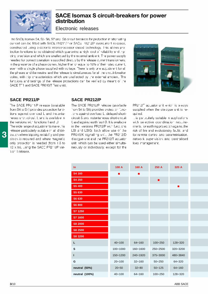
SACE Isomax S circuit-breakers for powerdistributionElectronic releases
The SACE Isomax S4, S5, S6, S7 and S8 circuit-breakers for protection in alternating
current can be fitted with SACE PR211/P or SACE PR212/P overcurrent releases,
constructed using electronic microprocessor-based technology. This allows pro-
tection functions to be obtained which guarantee a high level of reliability and trip-
ping precision and which are unaffected by the external ambient. The power supply
needed for correct operation is supplied directly by the release current transformers,
in the presence of a phase current higher than or equal to 18% of their rated current,
even with a single phase supplied with voltage. There is only one adjustment for all
the phases and the neutral and the release is simultaneous for all the circuit-breaker
poles, with trip characteristics which are unaffected by the external ambient. The
functions and settings of the release protections can be verified by means of the
SACE TT1 and SACE PR010/T Test units.
PR212/T actuator unit which is always
supplied when the dialogue unit is re-
quired.
It is particularly suitable in applications
with selective coordination require-
ments, for earthing protection against the
risk of fire and evolutionary faults, and
for remote control and parametrisation,
network supervision and centralised
load management.
The SACE PR212/P release (available
from S4 to S8) provides protection func-
tions against overload L, delayed short-
circuit S and instantaneous short-circuit
I, and against earth fault G. It is available
in the versions PR212/P with functions
LSI and LSIG; both allow use of the
PR010/K signalling unit, the PR212/D
dialogue unit and the PR212/T actuator
unit, which can be used either simulta-
neously or individually, except for the
The SACE PR211/P release (available
from S4 to S7) provides protection func-
tions against overload L and instanta-
neous short-circuit I, and is available in
the versions with functions I and LI.
The wide range of adjustments make this
release particularly suitable in all distri-
bution where tripping reliability and pre-
cision is required and where magnetic
only protection is needed (from 1.5 to
12 x In), using the SACE PR211/P ver-
sion I release.
neutral (50%)
neutral (100%)
SACE PR211/P SACE PR212/P
3/11ABB SACE
3
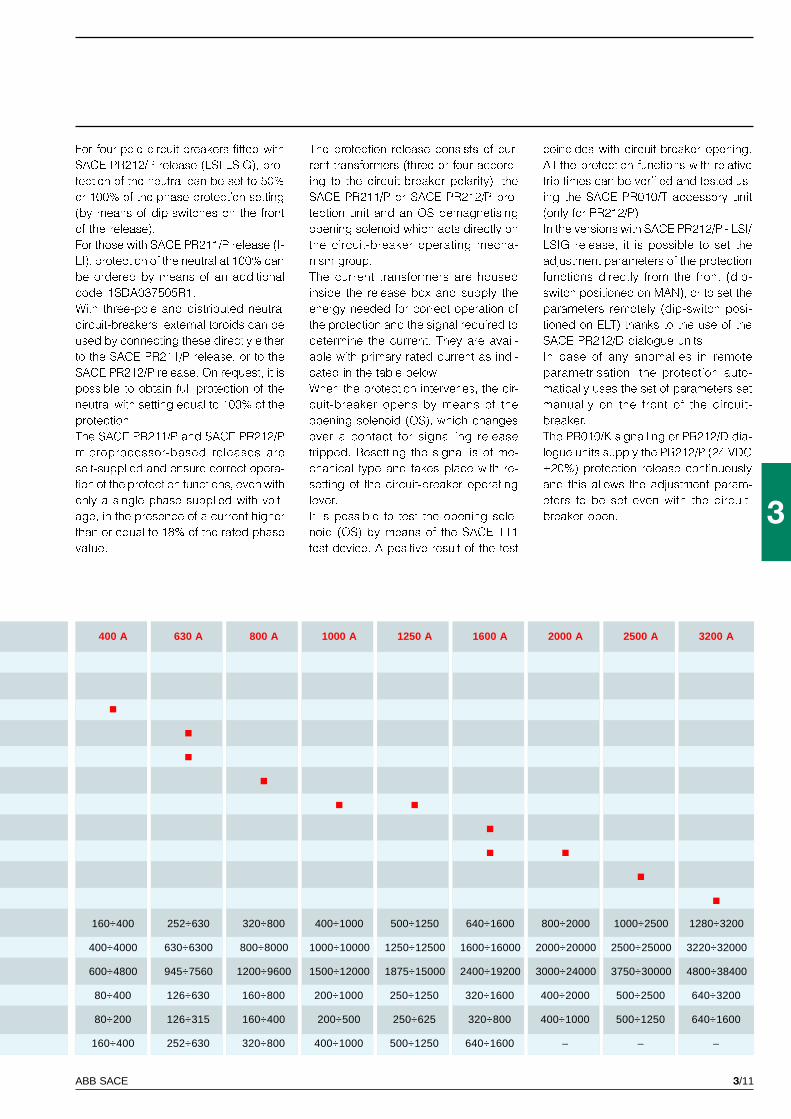
400 A 630 A 800 A 1000 A 1250 A 1600 A 2000 A 2500 A 3200 A
160÷400 252÷630 320÷800 400÷1000 500÷1250 640÷1600 800÷2000 1000÷2500 1280÷3200
400÷4000 630÷6300 800÷8000 1000÷10000 1250÷12500 1600÷16000 2000÷20000 2500÷25000 3220÷32000
600÷4800 945÷7560 1200÷9600 1500÷12000 1875÷15000 2400÷19200 3000÷24000 3750÷30000 4800÷38400
80÷400 126÷630 160÷800 200÷1000 250÷1250 320÷1600 400÷2000 500÷2500 640÷3200
80÷200 126÷315 160÷400 200÷500 250÷625 320÷800 400÷1000 500÷1250 640÷1600
160÷400 252÷630 320÷800 400÷1000 500÷1250 640÷1600 – – –
For four-pole circuit-breakers fitted with
SACE PR212/P release (LSI-LSIG), pro-
tection of the neutral can be set to 50%
or 100% of the phase protection setting
(by means of dip-switches on the front
of the release).
For those with SACE PR211/P release (I-
LI), protection of the neutral at 100% can
be ordered by means of an additional
code 1SDA037505R1.
With three-pole and distributed neutral
circuit-breakers, external toroids can be
used by connecting these directly either
to the SACE PR211/P release, or to the
SACE PR212/P release. On request, it is
possible to obtain full protection of the
neutral with setting equal to 100% of the
protection.
The SACE PR211/P and SACE PR212/P
microprocessor-based releases are
self-supplied and ensure correct opera-
tion of the protection functions, even with
only a single phase supplied with volt-
age, in the presence of a current higher
than or equal to 18% of the rated phase
value.
The protection release consists of cur-
rent transformers (three or four accord-
ing to the circuit-breaker polarity), the
SACE PR211/P or SACE PR212/P pro-
tection unit and an OS demagnetising
opening solenoid which acts directly on
the circuit-breaker operating mecha-
nism group.
The current transformers are housed
inside the release box and supply the
energy needed for correct operation of
the protection and the signal required to
determine the current. They are avail-
able with primary rated current as indi-
cated in the table below.
When the protection intervenes, the cir-
cuit-breaker opens by means of the
opening solenoid (OS), which changes
over a contact for signalling release
tripped. Resetting the signal is of me-
chanical type and takes place with re-
setting of the circuit-breaker operating
lever.
It is possible to test the opening sole-
noid (OS) by means of the SACE TT1
test device. A positive result of the test
coincides with circuit-breaker opening.
All the protection functions with relative
trip times can be verified and tested us-
ing the SACE PR010/T accessory unit
(only for PR212/P).
In the versions with SACE PR212/P - LSI/
LSIG release, it is possible to set the
adjustment parameters of the protection
functions directly from the front (dip-
switch positioned on MAN), or to set the
parameters remotely (dip-switch posi-
tioned on ELT) thanks to the use of the
SACE PR212/D dialogue units.
In case of any anomalies in remote
parametrisation, the protection auto-
matically uses the set of parameters set
manually on the front of the circuit-
breaker.
The PR010/K signalling or PR212/D dia-
logue units supply the PR212/P (24 VDC
±20%) protection release continuously
and this allows the adjustment param-
eters to be set even with the circuit-
breaker open.
3/12 ABB SACE
3
I2t=costOFF
I2t=costON
GS
IS90
54
SACE Isomax S circuit-breakersfor power distributionElectronic releases
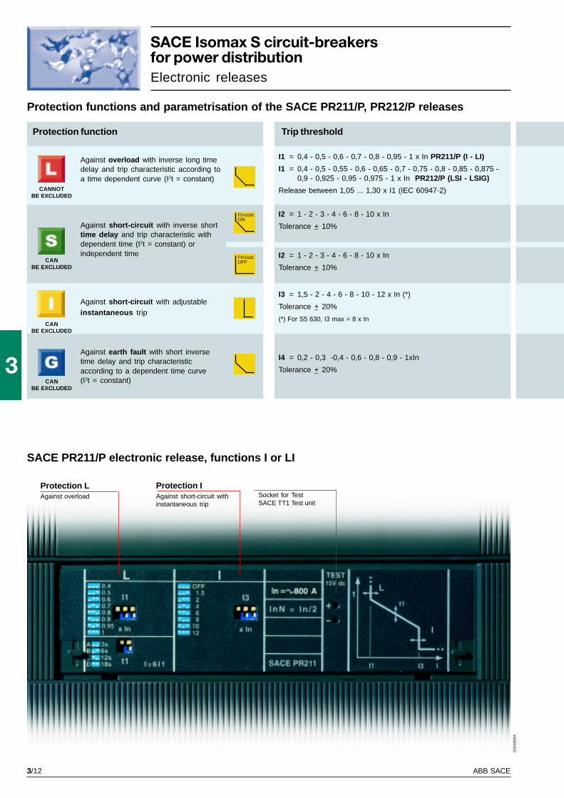
Protection functions and parametrisation of the SACE PR211/P, PR212/P releases
Protection LAgainst overload
Protection IAgainst short-circuit withinstantaneous trip
SACE PR211/P electronic release, functions I or LI
Against overload with inverse long timedelay and trip characteristic according toa time dependent curve (I2t = constant)
Against short-circuit with inverse shorttime delay and trip characteristic withdependent time (I2t = constant) orindependent time
Against short-circuit with adjustableinstantaneous trip
Against earth fault with short inversetime delay and trip characteristicaccording to a dependent time curve(I2t = constant)
Protection function Trip threshold
I1 = 0,4 - 0,5 - 0,6 - 0,7 - 0,8 - 0,95 - 1 x In PR211/P (I - LI)
I1 = 0,4 - 0,5 - 0,55 - 0,6 - 0,65 - 0,7 - 0,75 - 0,8 - 0,85 - 0,875 -0,9 - 0,925 - 0,95 - 0,975 - 1 x In PR212/P (LSI - LSIG)
Release between 1,05 ... 1,30 x I1 (IEC 60947-2)
I2 = 1 - 2 - 3 - 4 - 6 - 8 - 10 x In
Tolerance + 10%
I3 = 1,5 - 2 - 4 - 6 - 8 - 10 - 12 x In (*)
Tolerance + 20%
(*) For S5 630, I3 max = 8 x In
I4 = 0,2 - 0,3 -0,4 - 0,6 - 0,8 - 0,9 - 1xIn
Tolerance + 20%
I2 = 1 - 2 - 3 - 4 - 6 - 8 - 10 x In
Tolerance + 10%
Socket for TestSACE TT1 Test unit
CANNOTBE EXCLUDED
CANBE EXCLUDED
CANBE EXCLUDED
CANBE EXCLUDED
3/13ABB SACE
3
A B C D
GS
IS90
56
Protection SAgainst short-circuitwith delayed trip
Protection GAgainst earth fault
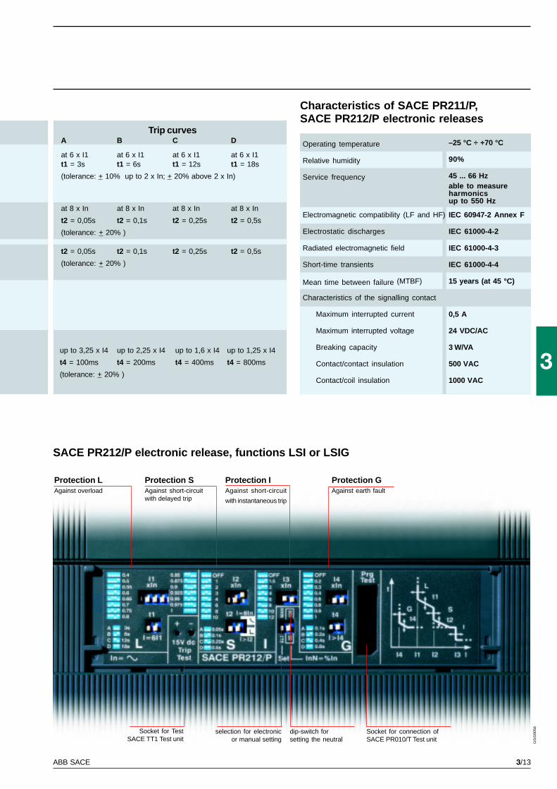
SACE PR212/P electronic release, functions LSI or LSIG
Trip curves
at 6 x I1 at 6 x I1 at 6 x I1 at 6 x I1t1 = 3s t1 = 6s t1 = 12s t1 = 18s
(tolerance: + 10% up to 2 x In; + 20% above 2 x In)
at 8 x In at 8 x In at 8 x In at 8 x In
t2 = 0,05s t2 = 0,1s t2 = 0,25s t2 = 0,5s
(tolerance: + 20% )
t2 = 0,05s t2 = 0,1s t2 = 0,25s t2 = 0,5s
(tolerance: + 20% )
up to 3,25 x I4 up to 2,25 x I4 up to 1,6 x I4 up to 1,25 x I4
t4 = 100ms t4 = 200ms t4 = 400ms t4 = 800ms
(tolerance: + 20% )
Protection LAgainst overload
Protection IAgainst short-circuit
with instantaneous trip
Socket for connection ofSACE PR010/T Test unit
Socket for TestSACE TT1 Test unit
dip-switch forsetting the neutral
selection for electronicor manual setting
Operating temperature –25 °C ÷ +70 °C
Relative humidity 90%
Service frequency 45 ... 66 Hzable to measureharmonicsup to 550 Hz
Electromagnetic compatibility (LF and HF) IEC 60947-2 Annex F
Electrostatic discharges IEC 61000-4-2
Radiated electromagnetic field IEC 61000-4-3
Short-time transients IEC 61000-4-4
Mean time between failure (MTBF) 15 years (at 45 °C)
Characteristics of the signalling contact
Maximum interrupted current 0,5 A
Maximum interrupted voltage 24 VDC/AC
Breaking capacity 3 W/VA
Contact/contact insulation 500 VAC
Contact/coil insulation 1000 VAC
Characteristics of SACE PR211/P,SACE PR212/P electronic releases
3/15
3
GS
IS90
64
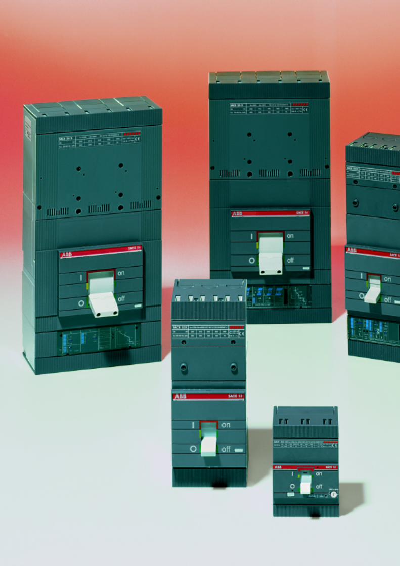
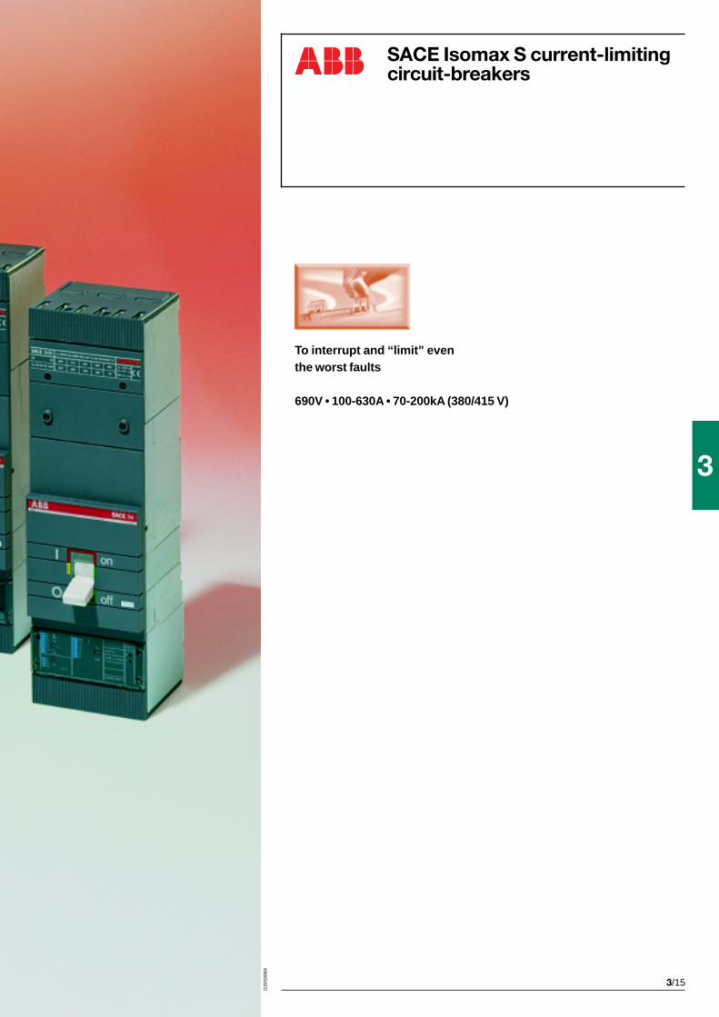
SACE Isomax S current-limitingcircuit-breakers
To interrupt and “limit” eventhe worst faults
690V • 100-630A • 70-200kA (380/415 V)
3/16 ABB SACE
3
SACE Isomax S2X 100
100
3
690
6
690
3000
X
100
70
70
50
10
75%
154
3,5
A
F-P
EF - FC - FC CuAl - R
FC-R
-
DIN EN 50022
25000/240
8000/120
90/120
70
120
1,1/1,5
1,3/1,7
-
GS
IS91
37
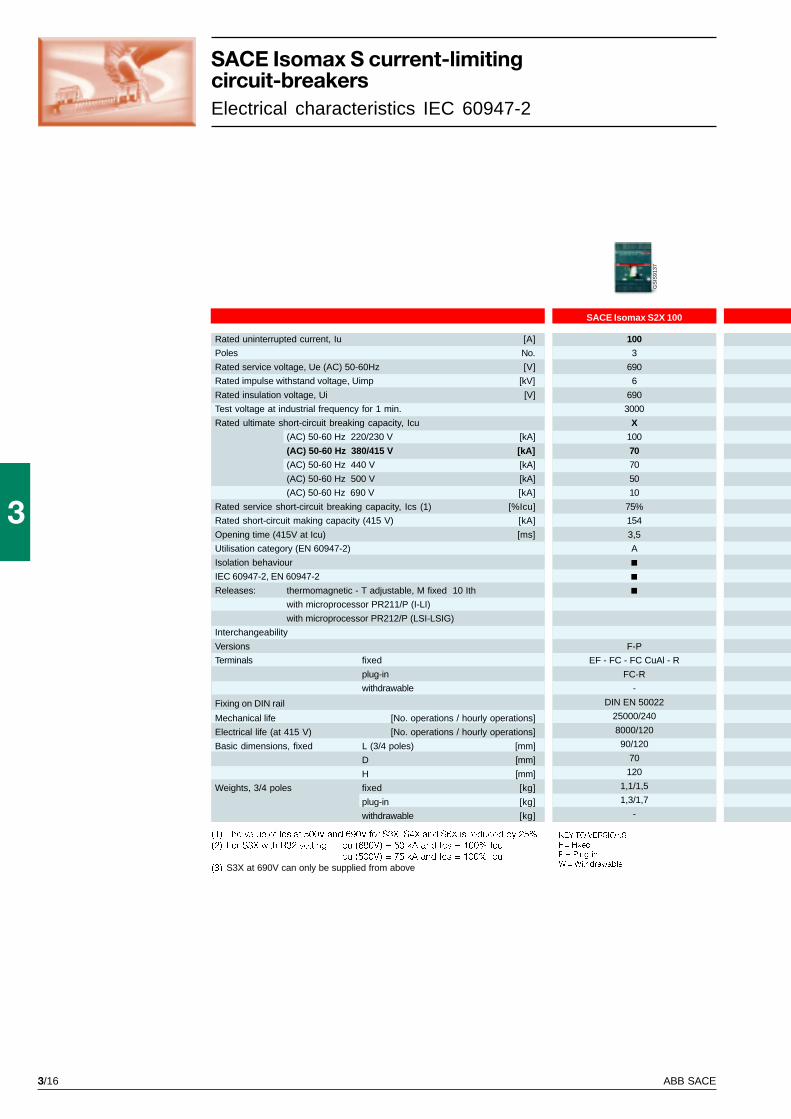
SACE Isomax S current-limitingcircuit-breakersElectrical characteristics IEC 60947-2
(1) The value of Ics at 500V and 690V for S3X, S4X and S6X is reduced by 25%
(2) For S3X with R32 setting: Icu (690V) = 50 kA and Ics = 100% Icu
Icu (500V) = 75 kA and Ics = 100% Icu
(3) S3X at 690V can only be supplied from above
Rated uninterrupted current, Iu [A]
Poles No.
Rated service voltage, Ue (AC) 50-60Hz [V]
Rated impulse withstand voltage, Uimp [kV]
Rated insulation voltage, Ui [V]
Test voltage at industrial frequency for 1 min.
Rated ultimate short-circuit breaking capacity, Icu
(AC) 50-60 Hz 220/230 V [kA]
(AC) 50-60 Hz 380/415 V [kA]
(AC) 50-60 Hz 440 V [kA]
(AC) 50-60 Hz 500 V [kA]
(AC) 50-60 Hz 690 V [kA]
Rated service short-circuit breaking capacity, Ics (1) [%Icu]
Rated short-circuit making capacity (415 V) [kA]
Opening time (415V at Icu) [ms]
Utilisation category (EN 60947-2)
Isolation behaviour
IEC 60947-2, EN 60947-2
Releases: thermomagnetic - T adjustable, M fixed 10 Ith
with microprocessor PR211/P (I-LI)
with microprocessor PR212/P (LSI-LSIG)
Interchangeability
Versions
Terminals fixed
plug-in
withdrawable
Fixing on DIN rail
Mechanical life [No. operations / hourly operations]
Electrical life (at 415 V) [No. operations / hourly operations]
Basic dimensions, fixed L (3/4 poles) [mm]
D [mm]
H [mm]
Weights, 3/4 poles fixed [kg]
plug-in [kg]
withdrawable [kg]
KEY TO VERSIONS
F = Fixed
P = Plug-in
W = Withdrawable
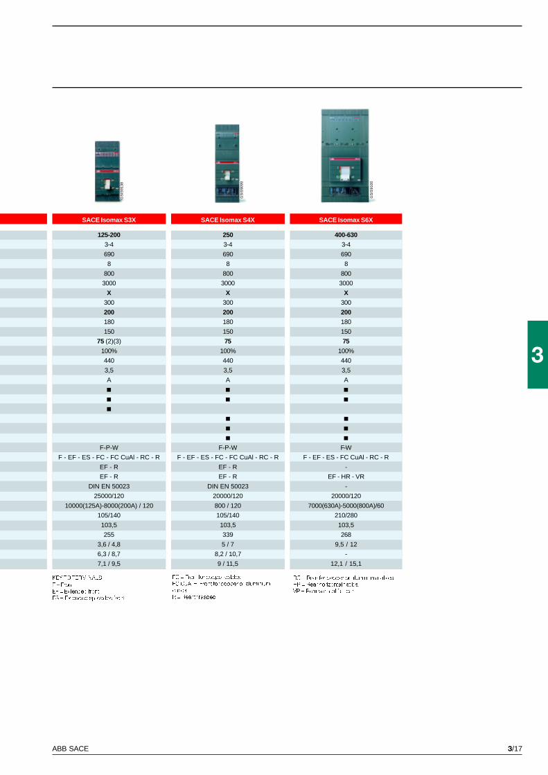
3/17ABB SACE
3
SACE Isomax S3X
125-200
3-4
690
8
800
3000
X
300
200
180
150
75 (2)(3)
100%
440
3,5
A
F-P-W
F - EF - ES - FC - FC CuAl - RC - R
EF - R
EF - R
DIN EN 50023
25000/120
10000(125A)-8000(200A) / 120
105/140
103,5
255
3,6 / 4,8
6,3 / 8,7
7,1 / 9,5
SACE Isomax S4X
250
3-4
690
8
800
3000
X
300
200
180
150
75
100%
440
3,5
A
F-P-W
F - EF - ES - FC - FC CuAl - RC - R
EF - R
EF - R
DIN EN 50023
20000/120
800 / 120
105/140
103,5
339
5 / 7
8,2 / 10,7
9 / 11,5
SACE Isomax S6X
400-630
3-4
690
8
800
3000
X
300
200
180
150
75
100%
440
3,5
A
F-W
F - EF - ES - FC CuAl - RC - R
-
EF - HR - VR
-
20000/120
7000(630A)-5000(800A)/60
210/280
103,5
268
9,5 / 12
-
12,1 / 15,1
GS
IS91
38
GS
IS90
99
GS
IS91
00
KEY TO TERMINALS
F = Front
EF = Extended front
ES = Extended spreaded front
FC = Front for copper cables
FC CuAl = Front for copper or aluminium
cables
R = Rear threaded
RC = Rear for copper or aluminium cables
HR = Rear horizontal flat bar
VR = Rear vertical flat bar
3/18 ABB SACE
3
GS
IS91
14
GS
IS90
29
GS
IS90
28
SACE Limitor SACE Isomax S
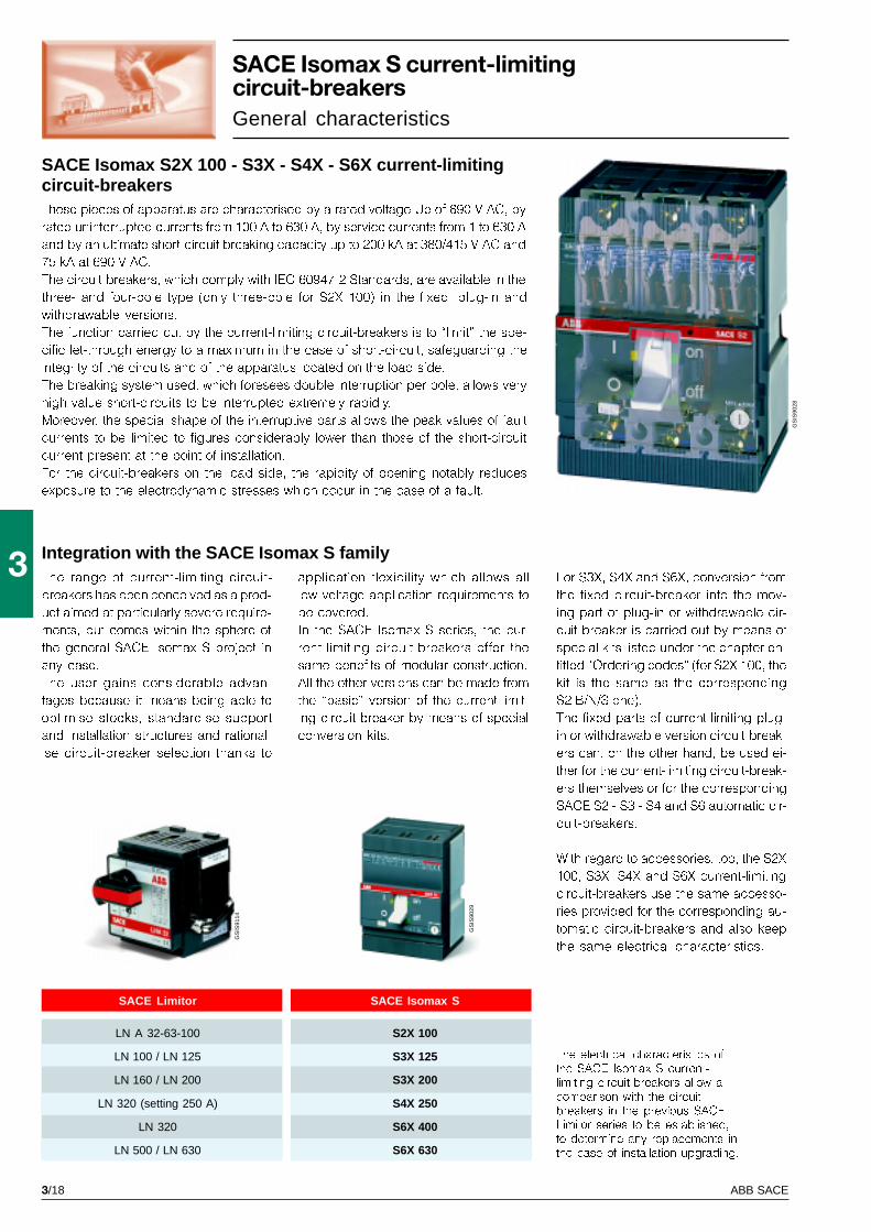
SACE Isomax S2X 100 - S3X - S4X - S6X current-limitingcircuit-breakersThese pieces of apparatus are characterised by a rated voltage Ue of 690 V AC, by
rated uninterrupted currents from 100 A to 630 A, by service currents from 1 to 630 A
and by an ultimate short-circuit breaking capacity up to 200 kA at 380/415 V AC and
75 kA at 690 V AC.
The circuit-breakers, which comply with IEC 60947-2 Standards, are available in the
three- and four-pole type (only three-pole for S2X 100) in the fixed, plug-in and
withdrawable versions.
The function carried out by the current-limiting circuit-breakers is to �limit� the spe-
cific let-through energy to a maximum in the case of short-circuit, safeguarding the
integrity of the circuits and of the apparatus located on the load side.
The breaking system used, which foresees double interruption per pole, allows very
high value short-circuits to be interrupted extremely rapidly.
Moreover, the special shape of the interruptive parts allows the peak values of fault
currents to be limited to figures considerably lower than those of the short-circuit
current present at the point of installation.
For the circuit-breakers on the load side, the rapidity of opening notably reduces
exposure to the electrodynamic stresses which occur in the case of a fault.
The electrical characteristics ofthe SACE Isomax S current-limiting circuit-breakers allow acomparison with the circuit-breakers in the previous SACELimitor series to be established,to determine any replacements inthe case of installation upgrading.
SACE Isomax S current-limitingcircuit-breakersGeneral characteristics
The range of current-limiting circuit-
breakers has been conceived as a prod-
uct aimed at particularly severe require-
ments, but comes within the sphere of
the general SACE Isomax S project in
any case.
The user gains considerable advan-
tages because it means being able to
optimise stocks, standardise support
and installation structures and rational-
ise circuit-breaker selection thanks to
For S3X, S4X and S6X, conversion from
the fixed circuit-breaker into the mov-
ing part of plug-in or withdrawable cir-
cuit-breaker is carried out by means of
special kits listed under the chapter en-
titled �Ordering codes� (for S2X 100, the
kit is the same as the corresponding
S2 B/N/S one).
The fixed parts of current-limiting plug-
in or withdrawable version circuit-break-
ers can, on the other hand, be used ei-
ther for the current-limiting circuit-break-
ers themselves or for the corresponding
SACE S2 - S3 - S4 and S6 automatic cir-
cuit-breakers.
With regard to accessories, too, the S2X
100, S3X, S4X and S6X current-limiting
circuit-breakers use the same accesso-
ries provided for the corresponding au-
tomatic circuit-breakers and also keep
the same electrical characteristics.
application flexibility which allows all
low voltage application requirements to
be covered.
In the SACE Isomax S series, the cur-
rent-limiting circuit-breakers offer the
same benefits of modular construction.
All the other versions can be made from
the �basic� version of the current-limit-
ing circuit-breaker by means of special
conversion kits.
Integration with the SACE Isomax S family
LN A 32-63-100 S2X 100
LN 100 / LN 125 S3X 125
LN 160 / LN 200 S3X 200
LN 320 (setting 250 A) S4X 250
LN 320 S6X 400
LN 500 / LN 630 S6X 630
3/19ABB SACE
3G
SIS
0084
The increased contact openingspeed, the dynamic blast actionproduced by the magnetic fieldand the structure of the arcingchamber contribute to extinguish-ing the arc in the shortestpossible time, limiting the specificlet-through energy value I2t andthe peak current.
ApplicationsThe current-limiting circuit-breakers are
suitable for installation in all types of
civil, industrial and service sector
plants, as well as in electrical installa-
tions on board ships, in mines, on off-
shore oil rigs and, generally, wherever
very high short-circuit currents can oc-
cur due to the high powers of the gen-
erators and transformers � up to 200 kA
at 380/415 V AC, 180 kA at 440 V AC
and 75kA at 690 V AC.
The circuit-breakers can be placed
near the power supply source both for
general protection (plants, user groups
and electrical lines) and for protection
of electric machines (motors, genera-
tors, transformers, capacitor banks).
Only the following are an exception:
� the mechanical interlocking plate for
two superimposed circuit-breakers
� the bracket for fixing onto DIN rail (for
S3X and S4X)
The wiring diagrams are those of the
corresponding SACE S2, S3, S4 and S6
circuit-breakers.
Apart from S2X 100 which are identical
to the corresponding S2 B/N/S, of the
circuit-breakers, the S3X, S4X and S6X
current-limiting circuit-breakers keep
the standardised depth of 103.5 mm,
standardised widths of 105 mm (S3X-
S4X) / 210mm (S6X) for the three-pole
versions and 140 mm (S3X-S4X) /
280mm (S6X) for the four-pole versions,
identical drilled fixing holes for the plug-
in and withdrawable versions and iden-
tical drilled holes for the compartment
door in all the versions and for all the
accessories.
Limitedlet-through current
Prospectiveshort-circuitcurrent
They can also be inserted in plants
where back-up protection is foreseen,
which allows use on the load side of cir-
cuit-breakers with breaking capacity
lower than the prospective short-circuit
current at the point of installation.
The breaking capacities of the SACE
Isomax S current-limiting circuit-break-
ers have exceeded the best perform-
ances achieved by other apparatus of
this type.
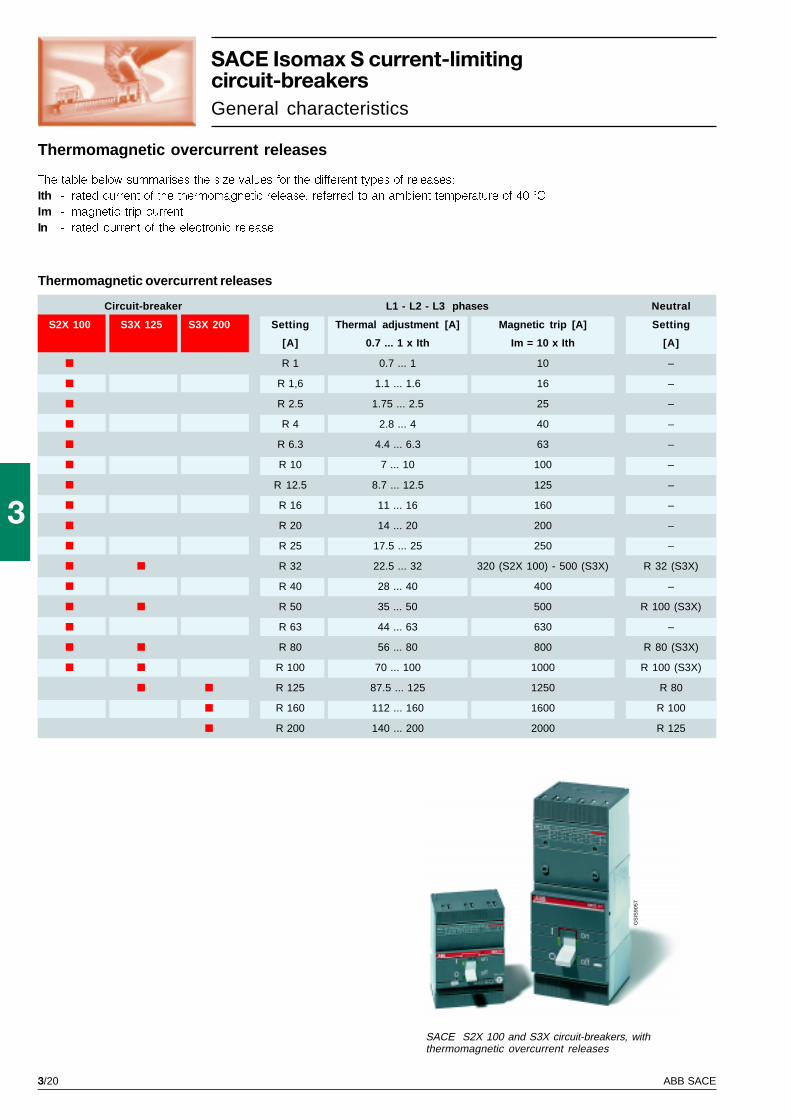
3/20 ABB SACE
3
GS
IS90
57
S2X 100 S3X 125 S3X 200
The table below summarises the size values for the different types of releases:
Ith - rated current of the thermomagnetic release, referred to an ambient temperature of 40 °C
Im - magnetic trip current
In - rated current of the electronic release
Thermomagnetic overcurrent releases
Thermomagnetic overcurrent releases
SACE Isomax S current-limitingcircuit-breakersGeneral characteristics
Circuit-breaker L1 - L2 - L3 phases Neutral
Setting Thermal adjustment [A] Magnetic trip [A] Setting
[A] 0.7 ... 1 x Ith Im = 10 x Ith [A]
R 1 0.7 ... 1 10 –
R 1,6 1.1 ... 1.6 16 –
R 2.5 1.75 ... 2.5 25 –
R 4 2.8 ... 4 40 –
R 6.3 4.4 ... 6.3 63 –
R 10 7 ... 10 100 –
R 12.5 8.7 ... 12.5 125 –
R 16 11 ... 16 160 –
R 20 14 ... 20 200 –
R 25 17.5 ... 25 250 –
R 32 22.5 ... 32 320 (S2X 100) - 500 (S3X) R 32 (S3X)
R 40 28 ... 40 400 –
R 50 35 ... 50 500 R 100 (S3X)
R 63 44 ... 63 630 –
R 80 56 ... 80 800 R 80 (S3X)
R 100 70 ... 100 1000 R 100 (S3X)
R 125 87.5 ... 125 1250 R 80
R 160 112 ... 160 1600 R 100
R 200 140 ... 200 2000 R 125
SACE S2X 100 and S3X circuit-breakers, withthermomagnetic overcurrent releases
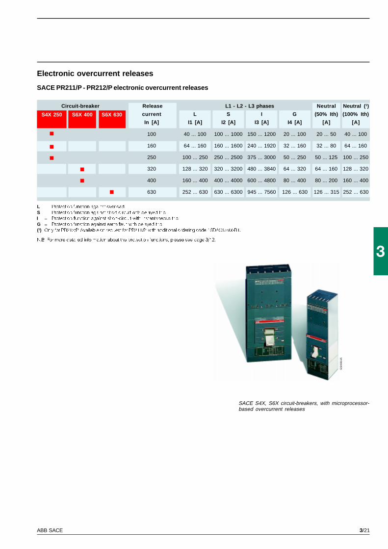
3/21ABB SACE
3
GS
IS91
15
S4X 250 S6X 400 S6X 630
L = Protection function against overload
S = Protection function against short-circuit with delayed trip
I = Protection function against short-circuit with instantaneous trip
G = Protection function against earth fault with delayed trip
(1) Only for PR212/P. Available on request for PR211/P, with additional ordering code 1SDA037505R1.
N.B. For more detailed information about the protection functions, please see page 3/12.
Electronic overcurrent releases
SACE PR211/P - PR212/P electronic overcurrent releases
SACE S4X, S6X circuit-breakers, with microprocessor-based overcurrent releases
Circuit-breaker Release L1 - L2 - L3 phases Neutral Neutral (1)
current L S I G (50% Ith) (100% Ith)
In [A] I1 [A] I2 [A] I3 [A] I4 [A] [A] [A]
100 40 ... 100 100 ... 1000 150 ... 1200 20 ... 100 20 ... 50 40 ... 100
160 64 ... 160 160 ... 1600 240 ... 1920 32 ... 160 32 ... 80 64 ... 160
250 100 ... 250 250 ... 2500 375 ... 3000 50 ... 250 50 ... 125 100 ... 250
320 128 ... 320 320 ... 3200 480 ... 3840 64 ... 320 64 ... 160 128 ... 320
400 160 ... 400 400 ... 4000 600 ... 4800 80 ... 400 80 ... 200 160 ... 400
630 252 ... 630 630 ... 6300 945 ... 7560 126 ... 630 126 ... 315 252 ... 630
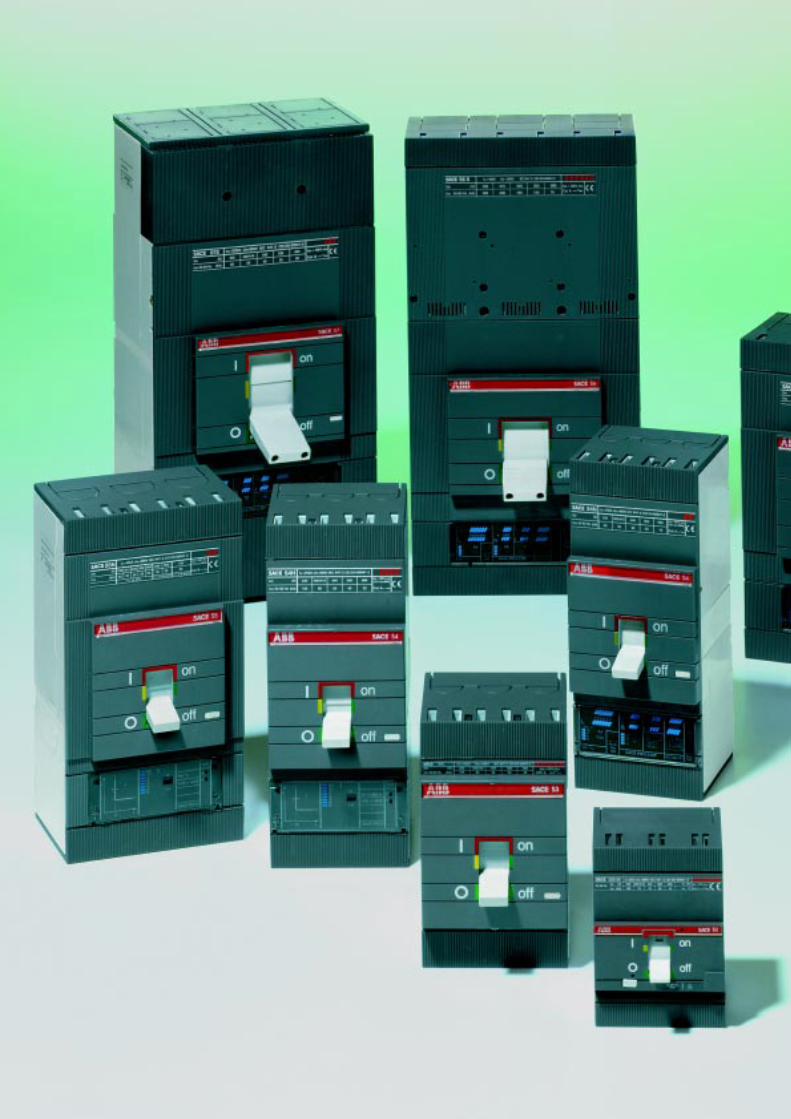
3/22 ABB SACE
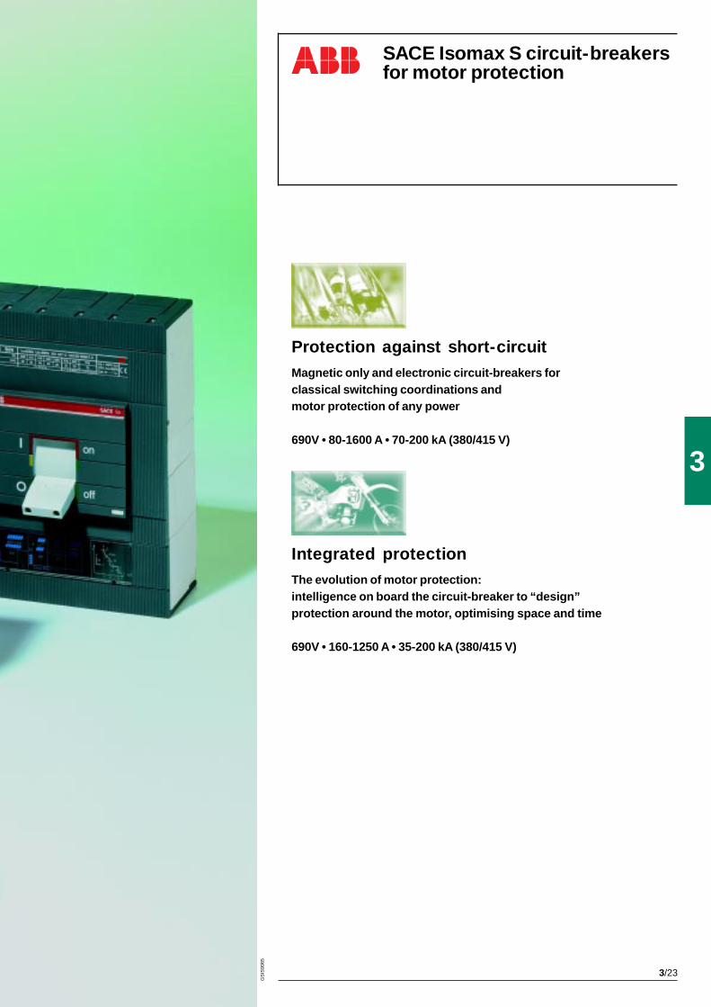
3/23
3
GS
IS90
65
Protection against short-circuitMagnetic only and electronic circuit-breakers forclassical switching coordinations andmotor protection of any power
690V • 80-1600 A • 70-200 kA (380/415 V)
SACE Isomax S circuit-breakersfor motor protection
Integrated protectionThe evolution of motor protection:intelligence on board the circuit-breaker to “design”protection around the motor, optimising space and time
690V • 160-1250 A • 35-200 kA (380/415 V)
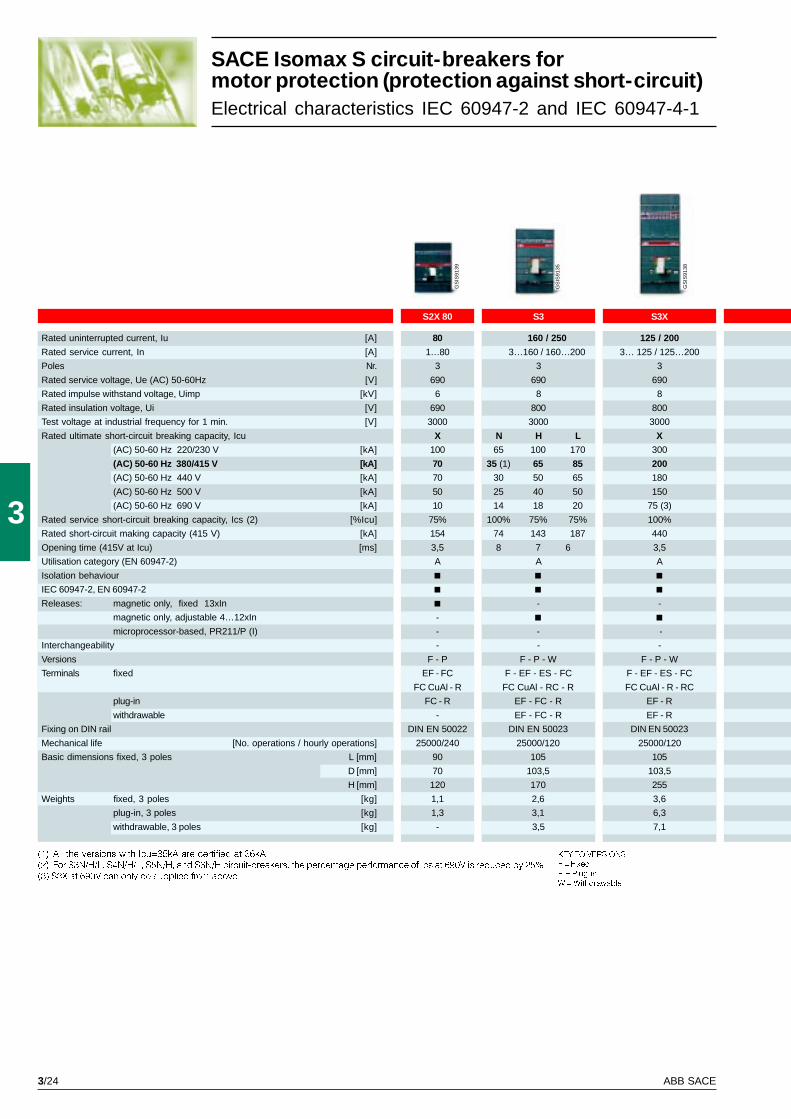
3/24 ABB SACE
3
S2X 80
80
1…80
3
690
6
690
3000
X
100
70
70
50
10
75%
154
3,5
A
-
-
-
F - P
EF - FC
FC CuAl - R
FC - R
-
DIN EN 50022
25000/240
90
70
120
1,1
1,3
-
S3
160 / 250
3…160 / 160…200
3
690
8
800
3000
N H L
65 100 170
35 (1) 65 85
30 50 65
25 40 50
14 18 20
100% 75% 75%
74 143 187
8 7 6
A
-
-
-
F - P - W
F - EF - ES - FC
FC CuAl - RC - R
EF - FC - R
EF - FC - R
DIN EN 50023
25000/120
105
103,5
170
2,6
3,1
3,5
S3X
125 / 200
3… 125 / 125…200
3
690
8
800
3000
X
300
200
180
150
75 (3)
100%
440
3,5
A
-
-
-
F - P - W
F - EF - ES - FC
FC CuAl - R - RC
EF - R
EF - R
DIN EN 50023
25000/120
105
103,5
255
3,6
6,3
7,1
GS
IS91
38
GS
IS91
35
GS
IS91
39
SACE Isomax S circuit-breakers formotor protection (protection against short-circuit)Electrical characteristics IEC 60947-2 and IEC 60947-4-1
Rated uninterrupted current, Iu [A]
Rated service current, In [A]
Poles Nr.
Rated service voltage, Ue (AC) 50-60Hz [V]
Rated impulse withstand voltage, Uimp [kV]
Rated insulation voltage, Ui [V]
Test voltage at industrial frequency for 1 min. [V]
Rated ultimate short-circuit breaking capacity, Icu
(AC) 50-60 Hz 220/230 V [kA]
(AC) 50-60 Hz 380/415 V [kA]
(AC) 50-60 Hz 440 V [kA]
(AC) 50-60 Hz 500 V [kA]
(AC) 50-60 Hz 690 V [kA]
Rated service short-circuit breaking capacity, Ics (2) [%Icu]
Rated short-circuit making capacity (415 V) [kA]
Opening time (415V at Icu) [ms]
Utilisation category (EN 60947-2)
Isolation behaviour
IEC 60947-2, EN 60947-2
Releases: magnetic only, fixed 13xIn
magnetic only, adjustable 4…12xIn
microprocessor-based, PR211/P (I)
Interchangeability
Versions
Terminals fixed
plug-in
withdrawable
Fixing on DIN rail
Mechanical life [No. operations / hourly operations]
Basic dimensions fixed, 3 poles L [mm]
D [mm]
H [mm]
Weights fixed, 3 poles [kg]
plug-in, 3 poles [kg]
withdrawable, 3 poles [kg]
(1) All the versions with Icu=35kA are certified at 36kA
(2) For S3N/H/L, S4N/H/L, S5N/H, and S6N/H circuit-breakers, the percentage performance of Ics at 690V is reduced by 25%
(3) S3X at 690V can only be supplied from above
KEY TO VERSIONS
F = Fixed
P = Plug-in
W = Withdrawable
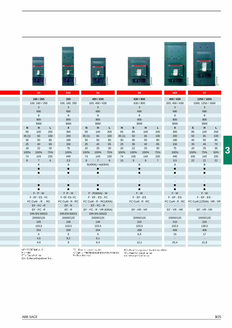
3/25ABB SACE
3
S4
160 / 250
100, 160 / 250
3
690
8
800
3000
N H L
65 100 200
35 (1) 65 100
30 50 80
25 40 65
18 22 30
100% 100% 75%
74 143 220
8 7 6
A
-
-
F - P - W
F - EF - ES - FC
FC CuAl - R - RC
EF - FC - R
EF - FC - R
DIN EN 50023
20000/120
105
103,5
254
4
4,5
4,9
S4X
250
100, 160, 250
3
690
8
800
3000
X
300
200
180
150
75
100%
440
3,5
A
-
-
F -P - W
F - EF - ES - FC
FC CuAl - R - RC
EF - R
EF - R
DIN EN 50023
20000/120
105
103,5
339
5
8,2
9
S5
400 / 630
320, 400 / 630
3
690
8
800
3000
N H L
65 100 200
35 (1) 65 100
30 50 80
25 40 65
20 25 30
100% 100% 75%
74 143 220
8 7 6
B(400A) / A(630A)
-
-
F - P(400A) - W
F - EF - ES - FC
FC CuAl - R - RC(400A)
EF - FC - R
EF - FC - R - VR (630A)
DIN EN 50023
20000/120
140
103,5
254
5
6,1
6,4
S6
630 / 800
630 / 800
3
690
8
800
3000
N S H L
65 85 100 200
35 (1) 50 65 100
30 45 50 80
25 35 40 65
20 22 25 30
100% 100% 100% 75%
74 105 143 220
10 9 8 7
B
-
-
F - W
F - EF - ES
FC CuAl - R - RC
-
EF - HR - VR
-
20000/120
210
103,5
268
9,5
-
12,1
S7
1250 / 1600
1000, 1250 / 1600
3
690
8
800
3000
S H L
85 100 200
50 65 100
40 55 80
35 45 70
20 25 35
100% 75% 50%
105 143 220
22 22 22
B
-
-
F - W
F - EF - ES -
FC CuAl (1250A) - HR - VR
-
EF - VR - HR
-
10000/120
210
138,5
406
17
-
21,8
S6X
400 / 630
320, 400 / 630
3
690
8
800
3000
X
300
200
180
150
75
100%
440
3,5
A
-
-
F - W
F - EF - ES
FC CuAl - R - RC
-
EF - VR - HR
-
20000/120
210
103,5
406
15
-
25,4
GS
IS91
01
GS
IS91
03
GS
IS91
02
GS
IS91
04
GS
IS91
05
GS
IS91
06
KEY TO TERMINALS
F = Front
EF = Extended front
ES = Extended spreaded front
FC = Front for copper cables
FC CuAl = Front for copper or aluminium cables
R = Rear threaded
RC = Rear for copper or aluminium cables
HR = Rear horizontal flat bar
VR = Rear vertical flat bar
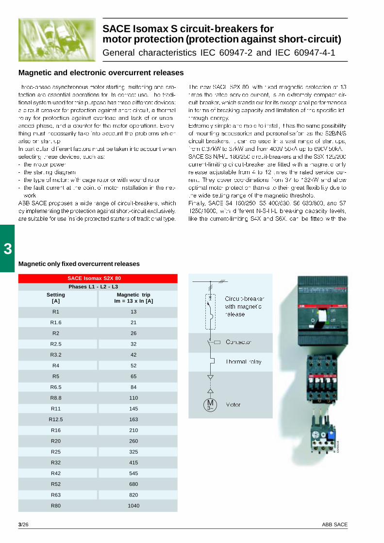
3/26 ABB SACE
3
GS
IS91
16
SACE Isomax S2X 80
Magnetic only fixed overcurrent releases
Magnetic and electronic overcurrent releases
Three-phase asynchronous motor starting, switching and pro-
tection are essential operations for its correct use. The tradi-
tional system used for this purpose has three different devices:
a circuit-breaker for protection against short-circuit, a thermal
relay for protection against overload and lack of or unbal-
anced phase, and a counter for the motor operations. Every-
thing must necessarily take into account the problems which
arise on start-up.
In particular, different factors must be taken into account when
selecting these devices, such as:
- the motor power
- the starting diagram
- the type of motor: with cage rotor or with wound rotor
- the fault current at the point of motor installation in the net-
work.
ABB SACE proposes a wide range of circuit-breakers, which
by implementing the protection against short-circuit exclusively,
are suitable for use inside protected starters of traditional type.
The new SACE S2X 80, with fixed magnetic protection at 13
times the rated service current, is an extremely compact cir-
cuit-breaker, which stands out for its exceptional performances
in terms of breaking capacity and limitation of the specific let-
through energy.
Extremely simple and rapid to install, it has the same possibility
of mounting accessories and personalisation as the S2B/N/S
circuit-breakers. It can be used in a vast range of start-ups,
from 0.37kW to 37kW and from 400V-50kA up to 690V-50kA.
SACE S3 N/H/L 160/250 circuit-breakers and the S3X 125/200
current-limiting circuit-breaker are fitted with a magnetic only
release adjustable from 4 to 12 times the rated service cur-
rent. They cover coordinations from 37 to 132kW and allow
optimal motor protection thanks to their great flexibility due to
the wide setting range of the magnetic threshold.
Finally, SACE S4 160/250, S5 400/630, S6 630/800, and S7
1250/1600, with different N-S-H-L breaking capacity levels,
like the current-limiting S4X and S6X, can be fitted with the
Motor
Circuit-breaker
with magnetic
release
Thermal relay
Contactor
Phases L1 - L2 - L3
Setting Magnetic trip[A] Im = 13 x In [A]
R1 13
R1.6 21
R2 26
R2.5 32
R3.2 42
R4 52
R5 65
R6.5 84
R8.8 110
R11 145
R12.5 163
R16 210
R20 260
R25 325
R32 415
R42 545
R52 680
R63 820
R80 1040
SACE Isomax S circuit-breakers formotor protection (protection against short-circuit)General characteristics IEC 60947-2 and IEC 60947-4-1
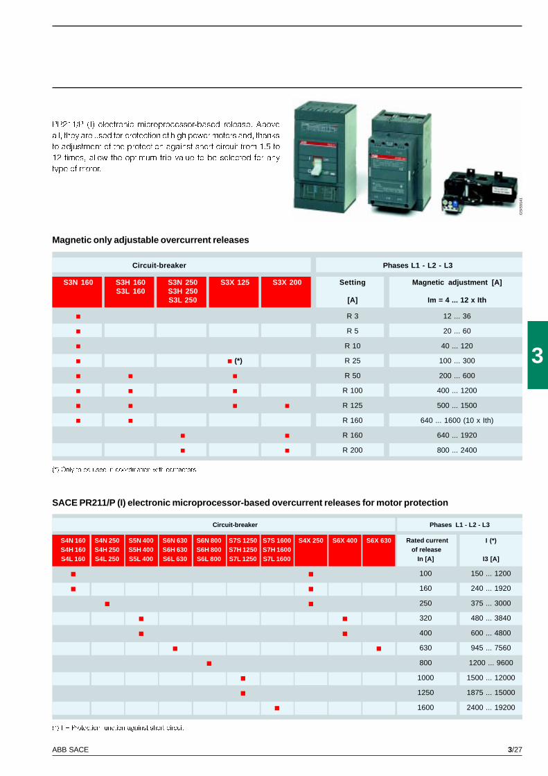
3/27ABB SACE
3
GS
IS91
41
S3N 160 S3H 160 S3N 250 S3X 125 S3X 200S3L 160 S3H 250
S3L 250 [A] Im = 4 ... 12 x Ith
R 3 12 ... 36
R 5 20 ... 60
R 10 40 ... 120
(*) R 25 100 ... 300
R 50 200 ... 600
R 100 400 ... 1200
R 125 500 ... 1500
R 160 640 ... 1600 (10 x Ith)
R 160 640 ... 1920
R 200 800 ... 2400
S4N 160 S4N 250 S5N 400 S6N 630 S6N 800 S7S 1250 S7S 1600 S4X 250 S6X 400 S6X 630 I (*)S4H 160 S4H 250 S5H 400 S6H 630 S6H 800 S7H 1250 S7H 1600S4L 160 S4L 250 S5L 400 S6L 630 S6L 800 S7L 1250 S7L 1600 In [A] I3 [A]
100 150 ... 1200
160 240 ... 1920
250 375 ... 3000
320 480 ... 3840
400 600 ... 4800
630 945 ... 7560
800 1200 ... 9600
1000 1500 ... 12000
1250 1875 ... 15000
1600 2400 ... 19200
Magnetic only adjustable overcurrent releases
SACE PR211/P (I) electronic microprocessor-based overcurrent releases for motor protection
(*) Only to be used in coordination with contactors
Circuit-breaker Phases L1 - L2 - L3
Setting Magnetic adjustment [A]
Circuit-breaker Phases L1 - L2 - L3
Rated currentof release
(*) I = Protection function against short-circuit
PR211/P (I) electronic microprocessor-based release. Above
all, they are used for protection of high power motors and, thanks
to adjustment of the protection against short-circuit from 1.5 to
12 times, allow the optimum trip value to be selected for any
type of motor.
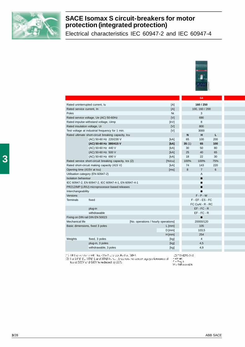
3/28 ABB SACE
3
S4
160 / 250
100, 160 / 200
3
690
8
800
3000
N H L
65 100 200
35 (1) 65 100
30 50 80
25 40 65
18 22 30
100% 100% 75%
74 143 220
8 7 6
A
F - P - W
F - EF - ES - FC
FC CuAl - R - RC
EF - FC - R
EF - FC - R
20000/120
105
103,5
254
4
4,5
4,9
GS
IS91
07
SACE Isomax S circuit-breakers for motorprotection (integrated protection)Electrical characteristics IEC 60947-2 and IEC 60947-4
(1) All the versions with Icu=35kA are certified at 36kA
(2) For S4N/H/L, S5N/H, and S6N/H circuit-breakers the percentage performance of
Ics at 500V and 690V is reduced by 25%
Rated uninterrupted current, Iu [A]
Rated service current, In [A]
Poles Nr.
Rated service voltage, Ue (AC) 50-60Hz [V]
Rated impulse withstand voltage, Uimp [kV]
Rated insulation voltage, Ui [V]
Test voltage at industrial frequency for 1 min. [V]
Rated ultimate short-circuit breaking capacity, Icu
(AC) 50-60 Hz 220/230 V [kA]
(AC) 50-60 Hz 380/415 V [kA]
(AC) 50-60 Hz 440 V [kA]
(AC) 50-60 Hz 500 V [kA]
(AC) 50-60 Hz 690 V [kA]
Rated service short-circuit breaking capacity, Ics (2) [%Icu]
Rated short-circuit making capacity (415 V) [kA]
Opening time (415V at Icu) [ms]
Utilisation category (EN 60947-2)
Isolation behaviour
IEC 60947-2, EN 60947-2, IEC 60947-4-1, EN 60947-4-1
PR212/MP (LRIU) microprocessor-based releases
Interchangeability
Versions
Terminals fixed
plug-in
withdrawable
Fixing on DIN rail DIN EN 50023
Mechanical life [No. operations / hourly operations]
Basic dimensions, fixed 3 poles L [mm]
D [mm]
H [mm]
Weights fixed, 3 poles [kg]
plug-in, 3 poles [kg]
withdrawable, 3 poles [kg]
KEY TO VERSIONS
F = Fixed
P = Plug-in
W = Withdrawable
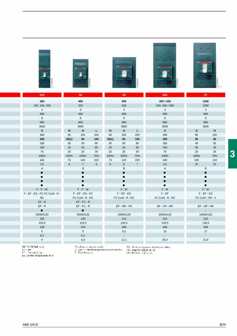
3/29ABB SACE
3
S5
400
320
3
690
8
800
3000
N H L
65 100 200
35(1) 65 100
30 50 80
25 40 65
20 25 30
100% 100% 75%
74 143 220
8 7 6
B
F - P - W
F - EF - ES - FC
FC CuAl - R - RC
EF - FC - R
EF - FC - R
20000/120
140
103,5
254
5
6,1
6,4
S7
1250
1000
3
690
8
800
3000
S H
85 100
50 65
40 55
35 45
20 25
100% 75%
105 143
22 22
B
F - W
F - EF - ES
FC CuAl - HR - V
-
EF - VR - HR
-
10000/120
210
138,5
406
17
-
21,8
S6X
400 / 630
320, 400 / 630
3
690
8
800
3000
X
300
200
180
150
75
100%
440
3,5
A
F - W
F - EF
FC CuAl - R - RC
-
EF - VR - HR
-
20000/120
210
103,5
406
15
-
25,4
S6
630
630
3
690
8
800
3000
N H L
65 100 200
35(1) 65 100
30 50 80
25 40 65
20 25 30
100% 100% 75%
74 143 220
9 8 7
B
F - W
F - EF - ES
FC CuAl - R - RC
-
EF - HR - VR
-
20000/120
210
103,5
268
9,5
-
12,1
S4X
250
100, 160, 200
3
690
8
800
3000
X
300
200
180
150
75
100%
440
3,5
A
F - P - W
F - EF - ES - FC FC CuAl - R -
RC
EF - R
EF - R
20000/120
105
103,5
339
5
8,2
9
GS
IS91
08
GS
IS91
09
GS
IS91
10
GS
IS91
11
GS
IS91
12
KEY TO TERMINALS
F = Front
EF = Extended front
ES = Extended spreaded front
FC = Front for copper cables
FC CuAl = Front for copper or aluminium cables
R = Rear threaded
RC = Rear for copper or aluminium cables
HR = Rear horizontal flat bar
VR = Rear vertical flat bar
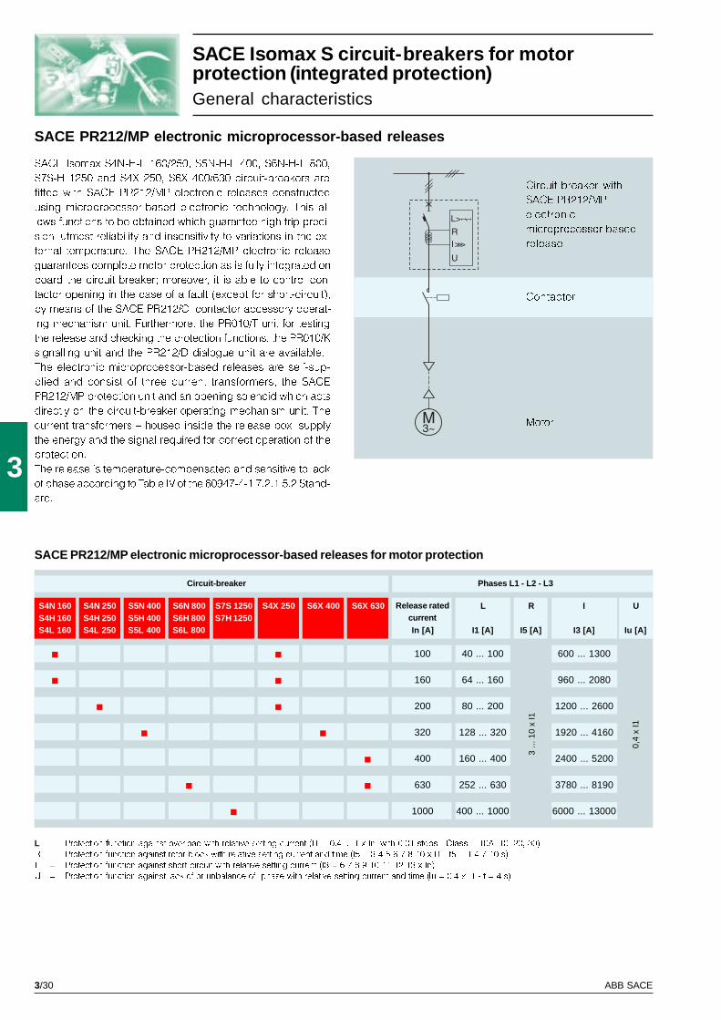
3/30 ABB SACE
3
3 ...
10
x I1
0,4
x I1
S4N 160 S4N 250 S5N 400 S6N 800 S7S 1250 S4X 250 S6X 400 S6X 630 L R I US4H 160 S4H 250 S5H 400 S6H 800 S7H 1250S4L 160 S4L 250 S5L 400 S6L 800 In [A] I1 [A] I5 [A] I3 [A] Iu [A]
100 40 ... 100 600 ... 1300
160 64 ... 160 960 ... 2080
200 80 ... 200 1200 ... 2600
320 128 ... 320 1920 ... 4160
400 160 ... 400 2400 ... 5200
630 252 ... 630 3780 ... 8190
1000 400 ... 1000 6000 ... 13000
L = Protection function against overload with relative setting current (I1 = 0.4 ... 1 x In, with 0.01 steps - Class = 10A, 10, 20, 30)
R = Protection function against rotor block with relative setting current and time (I5 = 3-4-5-6-7-8-10 x I1 - t5 = 1-4-7-10 s)
I = Protection function against short-circuit with relative setting current (I3 = 6-7-8-9-10-11-12-13 x In)
U = Protection function against lack of or unbalance of phase with relative setting current and time (Iu = 0.4 x I1 - t = 4 s)
SACE PR212/MP electronic microprocessor-based releases for motor protection
SACE Isomax S circuit-breakers for motorprotection (integrated protection)General characteristics
SACE PR212/MP electronic microprocessor-based releases
Motor
Circuit-breaker with
SACE PR212/MP
electronic
microprocessor-based
release
Contactor
SACE Isomax S4N-H-L 160/250, S5N-H-L 400, S6N-H-L 800,
S7S-H 1250 and S4X 250, S6X 400/630 circuit-breakers are
fitted with SACE PR212/MP electronic releases constructed
using microprocessor-based electronic technology. This al-
lows functions to be obtained which guarantee high trip preci-
sion, utmost reliability and insensitivity to variations in the ex-
ternal temperature. The SACE PR212/MP electronic release
guarantees complete motor protection as is fully integrated on
board the circuit-breaker; moreover, it is able to control con-
tactor opening in the case of a fault (except for short-circuit),
by means of the SACE PR212/CI contactor accessory operat-
ing mechanism unit. Furthermore, the PR010/T unit for testing
the release and checking the protection functions, the PR010/K
signalling unit and the PR212/D dialogue unit are available.
The electronic microprocessor-based releases are self-sup-
plied and consist of three current transformers, the SACE
PR212/MP protection unit and an opening solenoid which acts
directly on the circuit-breaker operating mechanism unit. The
current transformers � housed inside the release box, supply
the energy and the signal required for correct operation of the
protection.
The release is temperature-compensated and sensitive to lack
of phase according to Table IV of the 60947-4-1 7.2.1.5.2 Stand-
ard.
Circuit-breaker Phases L1 - L2 - L3
Release ratedcurrent
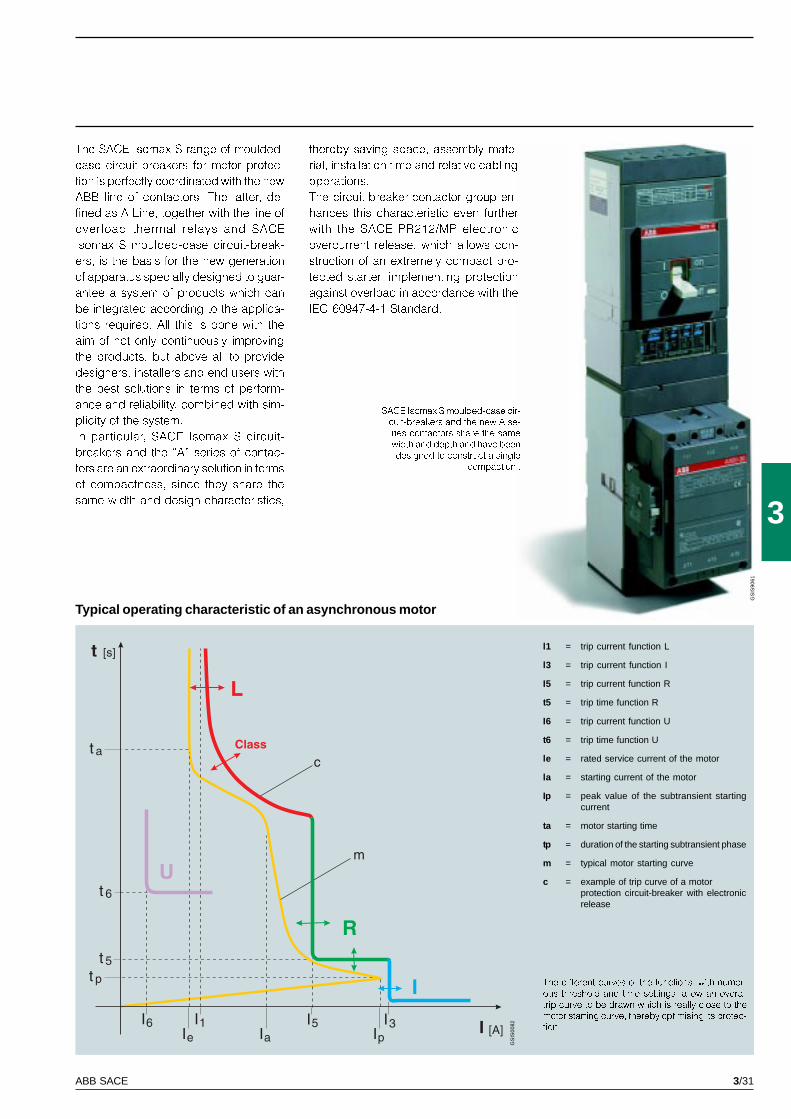
3/31ABB SACE
3
GS
IS90
61
GS
IS00
82
SACE Isomax S moulded-case cir-
cuit-breakers and the new A se-
ries contactors share the same
width and depth and have been
designed to construct a single
compact unit
Typical operating characteristic of an asynchronous motor
The different curves of the functions, with numer-
ous threshold and time settings, allow an overall
trip curve to be drawn which is really close to the
motor starting curve, thereby optimising its protec-
tion
l1 = trip current function L
l3 = trip current function I
I5 = trip current function R
t5 = trip time function R
I6 = trip current function U
t6 = trip time function U
le = rated service current of the motor
la = starting current of the motor
Ip = peak value of the subtransient startingcurrent
ta = motor starting time
tp = duration of the starting subtransient phase
m = typical motor starting curve
c = example of trip curve of a motorprotection circuit-breaker with electronicrelease
The SACE Isomax S range of moulded-
case circuit-breakers for motor protec-
tion is perfectly coordinated with the new
ABB line of contactors. The latter, de-
fined as A-Line, together with the line of
overload thermal relays and SACE
Isomax S moulded-case circuit-break-
ers, is the basis for the new generation
of apparatus specially designed to guar-
antee a system of products which can
be integrated according to the applica-
tions required. All this is done with the
aim of not only continuously improving
the products, but above all to provide
designers, installers and end users with
the best solutions in terms of perform-
ance and reliability, combined with sim-
plicity of the system.
In particular, SACE Isomax S circuit-
breakers and the �A� series of contac-
tors are an extraordinary solution in terms
of compactness, since they share the
same width and design characteristics,
thereby saving space, assembly mate-
rial, installation time and relative cabling
operations.
The circuit-breaker-contactor group en-
hances this characteristic even further
with the SACE PR212/MP electronic
overcurrent release, which allows con-
struction of an extremely compact pro-
tected starter, implementing protection
against overload in accordance with the
IEC 60947-4-1 Standard.
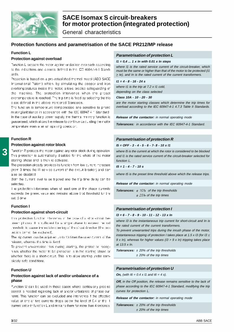
3/32 ABB SACE
3
SACE Isomax S circuit-breakersfor motor protection (integrated protection)General characteristics
Parametrisation of protection UOn, (with I6 = 0.4 x l1 and t6 = 4 s).
Off, in the Off position, the release remains sensitive to the lack of
phase according to the IEC 60947-4-1 Standard, modifying the trip
curves for protection L.
Release of the contactor: in normal operating mode
Tolerances: ± 20% of the trip thresholds
± 20% of the trip times
Function U
Protection against lack of and/or unbalance of aphase
Function U can be used in those cases where particularly precise
control is needed regarding lack of and/or unbalance of phase cur-
rents. This function can be excluded and intervenes if the effective
value of one or two currents drops below the level of 0.4 of the l1
current set with function L and remains there for more than 4 seconds.
Function L
Protection against overload
Function L protects the motor against undesired overloads according
to the indications and classes defined in the IEC 60947-4-1 Stand-
ards.
Protection is based on a pre-established thermal model (ABB SACE
International Patent) which, by simulating the copper and iron
overtemperatures inside the motor, allows precise safeguarding of
the machine. The protection intervenes when the preset
overtemperature is reached. The trip time is fixed by selecting the trip
class defined in the above-mentioned Standards.
The function is temperature-compensated and sensitive to phase
missing/unbalance in accordance with the IEC 60947-4-1 Standard.
In the case of auxiliary power supply, the thermal memory function is
guaranteed, which allows the release to continue calculating the motor
temperature even after an opening operation.
Protection functions and parametrisation of the SACE PR212/MP release
Function RProtection against rotor block
Function R protects the motor against any rotor block during operation.
This protection is automatically disabled for the whole of the motor
starting phase and is then re-activated.
The protection already provides its function from low current increases
(from 3 times the l1 service current of the circuit-breaker) and can
also be disabled.
Both the current level to be tripped and the trip time delay can be
selected.
The protection intervenes when at least one of the phase currents
exceeds the preset value and remains above that threshold for the
set t5 time.
Function I
Protection against short-circuit
This protection function intervenes in the case of a short-circuit be-
tween phases. It is sufficient for a single phase to exceed the set
threshold to cause immediate opening of the circuit-breaker (the pro-
tection cannot be excluded).
The trip current can be adjusted up to 13 times the rated current of the
release, whereas the time is fixed.
To prevent unwarranted trips during starting, the protection recog-
nises whether the motor to be protected is in the starting phase or
whether there is a short-circuit. This is to allow starting under com-
pletely safe conditions.
Parametrisation of protection Rl5 = OFF - 3 - 4 - 5 - 6 - 7- 8 - 10 x l1
where l5 is the current at which the rotor is considered to be blocked
and l1 is the rated service current of the circuit-breaker selected for
function L.
t5 = 1 - 4 - 7 - 10 s
where t5 is the preset time threshold above which the release trips.
Release of the contactor: in normal operating mode
Tolerances: ± 10% of the trip thresholds
± 20% of the trip times
Parametrisation of protection Il3 = 6 - 7 - 8 - 9 - 10 - 11 - 12 - 13 x In
where I3 is the instantaneous trip current for short-circuit and In is
the rated current of the current transformers.
To prevent unwarranted trips during the inrush phase of the motor,
instantaneous tripping of protection I takes place at 1.5 x I3 (for I3 <
9 x In), whereas for higher values (I3 > 9 x In) tripping takes place
at 13.5 x In.
Tolerances: ± 20% of the trip thresholds
± 20% of the trip times
Parametrisation of protection Ll1 = 0,4 ... 1 x In with 0.01 x In steps
where l1 is the rated service current of the circuit-breaker, whichmust be the same or higher than that of the motor to be protected (I1> Ie), and In is the rated current of the current transformers.
t1 = 4 - 8 - 16 - 24 s
where t1 is the trip at 7.2 x I1 cold,
depending on the class selected
Class 10A - 10 - 20 - 30
are the motor starting classes which determine the trip times foroverload according to the IEC 60947-4-1 4.7.3 Table II Standards.
Release of the contactor: in normal operating mode
Tolerances: in accordance with the IEC 60947-4-1 Standard.
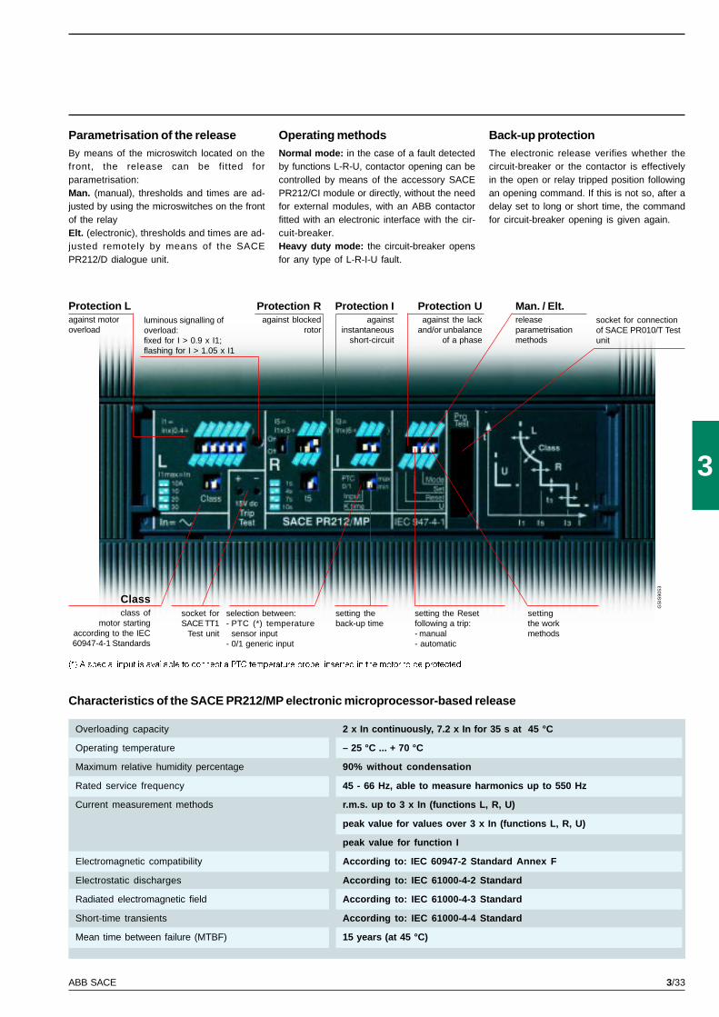
3/33ABB SACE
3
GS
IS90
53
Characteristics of the SACE PR212/MP electronic microprocessor-based release
Parametrisation of the releaseBy means of the microswitch located on thefront, the release can be fitted forparametrisation:Man. (manual), thresholds and times are ad-justed by using the microswitches on the frontof the relayElt. (electronic), thresholds and times are ad-justed remotely by means of the SACEPR212/D dialogue unit.
Overloading capacity 2 x In continuously, 7.2 x In for 35 s at 45 °C
Operating temperature – 25 °C ... + 70 °C
Maximum relative humidity percentage 90% without condensation
Rated service frequency 45 - 66 Hz, able to measure harmonics up to 550 Hz
Current measurement methods r.m.s. up to 3 x In (functions L, R, U)
peak value for values over 3 x In (functions L, R, U)
peak value for function I
Electromagnetic compatibility According to: IEC 60947-2 Standard Annex F
Electrostatic discharges According to: IEC 61000-4-2 Standard
Radiated electromagnetic field According to: IEC 61000-4-3 Standard
Short-time transients According to: IEC 61000-4-4 Standard
Mean time between failure (MTBF) 15 years (at 45 °C)
Operating methodsNormal mode: in the case of a fault detectedby functions L-R-U, contactor opening can becontrolled by means of the accessory SACEPR212/CI module or directly, without the needfor external modules, with an ABB contactorfitted with an electronic interface with the cir-cuit-breaker.Heavy duty mode: the circuit-breaker opensfor any type of L-R-I-U fault.
(*) A special input is available to connect a PTC temperature probe, inserted in the motor to be protected
Protection Lagainst motoroverload
Protection Ragainst blocked
rotor
Protection Iagainst
instantaneousshort-circuit
Classclass of
motor startingaccording to the IEC60947-4-1 Standards
Protection Uagainst the lack
and/or unbalanceof a phase
Man. / Elt.releaseparametrisationmethods
socket forSACE TT1
Test unit
selection between:- PTC (*) temperature
sensor input- 0/1 generic input
setting theback-up time
setting the Resetfollowing a trip:- manual- automatic
settingthe workmethods
luminous signalling ofoverload:fixed for I > 0.9 x I1;flashing for I > 1.05 x I1
socket for connectionof SACE PR010/T Testunit
Back-up protectionThe electronic release verifies whether thecircuit-breaker or the contactor is effectivelyin the open or relay tripped position followingan opening command. If this is not so, after adelay set to long or short time, the commandfor circuit-breaker opening is given again.

3/34 ABB SACE

3/35
3
GS
IS90
66
Taking the SACE Isomax S limits higher and higher
1000 V • 160-800 A • 6-50 kA
SACE Isomax S circuit-breakersfor applications up to 1000V

3/36 ABB SACE
3
S3
160
3
1000
8
1000
3000
L
6
9,2
20
A
F
F
DIN EN 50023
25000/120
105
103,5
170
2,6
S3
160-250
4
1000
8
1000
3000
L
40
40
25
–
A
–
F
F
DIN EN 50023
25000/120
140
103,5
170
3,5
S5
400
4
1000
8
1000
3000
L
40
40
35
5
B
–
F
F
DIN EN 50023
20000/120
184
103,5
254
7
S6
630
4
1000
8
1000
3000
L
40
40
45
7,6
B
–
F
F
–
20000/120
280
103,5
268
12
S6
800
4
1000
8
1000
3000
L
50
50
50
10
B
–
F
F
–
20000/120
280
103,5
268
12
VVVVV–––––
VVVVV~~~~~VVVVV~~~~~
VVVVV–––––
Within the panorama of Isomax propos-als, there is also the range of circuit-breakers and switch-disconnectors fordirect current and alternating currentapplications up to 1000V.The typical application sectors are in-stallations in mines, road or railway tun-nels, traction and industrial applicationsin general.The circuit-breakers for direct current(connection diagrams on page 5/47) areavailable in the four-pole version,whereas those for alternating current areavailable in the three-pole version, withadjustable or electronic thermomagneticreleases and have the same dimensionsas the standard versions.They can also be combined with all theaccessories available for the Isomaxseries.
SACE Isomax S circuit-breakersfor applications up to 1000VElectrical and general characteristics IEC 60947-2
Range at 1000 V in a.c.
Range at 1000 V in d.c.
Rated uninterrupted current, Iu [A]
Poles Nr.
Rated service voltage, Ue (AC) 50-60Hz [V]
Rated impulse withstand voltage, Uimp [kV]
Rated insulation voltage, Ui [V]
Test voltage at industrial frequency for 1 min.
Rated ultimate short-circuit breaking capacity,
Icu (AC) 50-60 Hz 1000 V [kA]
Rated short-circuit making capacity [kA]
Opening time [ms]
Rated short-time withstand current for 1 s, Icw [kA]
Utilisation category (EN 60947-2)
Isolation behaviour
IEC 60947-2, EN 60947-2
Thermomagnetic releases T adjustable, M fixed 10 Ith
PR211/P (LI only) microprocessor-based releases
PR212/P (LSI-LSIG) microprocessor-based releases
Versions
Terminals
Fixing on DIN rail
Mechanical life [No. operations / hourly operations]
Dimensions L [mm]
D [mm]
H [mm]
Weights [kg]
Rated uninterrupted current, Iu [A]
Poles Nr.
Rated service voltage, Ue [V –]
Rated impulse withstand voltage, Uimp [kV]
Rated insulation voltage, Ui [V]
Test voltage at industrial frequency for 1 min.
Ultimate rated short-circuit breaking capacity, Icu
(4 poles in series) [kA]
Rated short-circuit making capacity [kA]
Opening time [ms]
Rated short-time withstand current for 1 s, Icw [kA]
Utilisation category (EN 60947-2)
Isolation behaviour
IEC 60947-2, EN 60947-2
Thermomagnetic releases, T adjustable - M fixed 10 Ith
Thermomagnetic releases, T adjustable - M adjustable
Versions
Terminals
Fixing on DIN rail
Mechanical life [No. operations / hourly operations]
Basic dimensions, fixed L [mm]
D [mm]
H [mm]
Weights, fixed [kg]
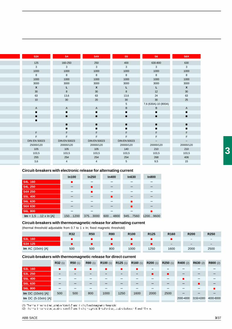
3/37ABB SACE
3
S6X
630
3
1000
8
1000
3000
X
30
63
25
A
F
F
–
20000/120
210
103,5
406
15
S4
160-250
3
1000
8
1000
3000
L
8
13,6
30
A
F
F
DIN EN 50023
20000/120
105
103,5
254
4
S6
630-800
3
1000
8
1000
3000
L
12
24
30
7,6 (630A)-10 (800A)
B
F
F
–
20000/120
210
103,5
268
9,5
S3X
125
3
1000
8
1000
3000
X
30
63
10
A
F
F
DIN EN 50023
25000/120
105
103,5
255
3,6
S4X
250
3
1000
8
1000
3000
X
30
63
20
A
F
F
DIN EN 50023
20000/120
105
103,5
254
4
S5
400
3
1000
8
1000
3000
L
8
13,6
30
5
B
F
F
DIN EN 50023
20000/120
140
103,5
254
5
R32 R50 R80 R100 R125 R160 R200 R250
S3L 160 – –
S3X 125 – – –
500 500 800 1000 1250 1600 2000 2500
R32 (1) R50 (1) R80 (1) R100 (1) R125 (1) R160 (1) R200 (1) R250 (1) R400 (2) R630 (2) R800 (2)
S3L 160 – – – – –S3L 250 – – – – – – – – –S5L 400 – – – – – – – – – –S6L 630 – – – – – – – – – –S6L 800 – – – – – – – – – –
500 500 800 1000 1250 1600 2000 2500 – – –2000-4000 3150-6300 4000-8000
In100 In250 In400 In630 In800
S4L 160 – – – –S4L 250 – – – –S4X 250 – – – –S5L 400 – – – –S6L 630 – – – –S6X 630 – – – –S6L 800 – – – –Im = 1,5 …12 x In [A] 150…1200 375…3000 600 ... 4800 945…7560 1200…9600
Circuit-breakers with electronic release for alternating current
Circuit-breakers with thermomagnetic release for alternating current(thermal threshold adjustable from 0.7 to 1 x In; fixed magnetic threshold)
(1) Thermal threshold adjustable from 0.7 and 1 x In; fixed magnetic threshold(2) Thermal threshold adjustable from 0.7 and 1 x In; magnetic threshold adjustable between 5 and 10 x In.
Circuit-breakers with thermomagnetic release for direct current
Im AC (10xIn) [A]
Im DC (10xIn) [A]
Im DC (5-10xIn) [A]

3/38 ABB SACE
3/39
3
GS
IS90
67
Close, carry and isolate.The certainty of operating in complete safety.
690 V • 125-3200 A • 3,1-85 KA (Icm) • 2,2-40 kA (Icw)
SACE Isomax Sswitch-disconnectors
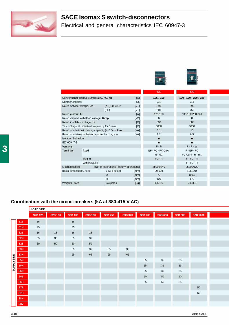
3/40 ABB SACE
3
S3D
100 / 160 / 250 / 320
3/4
690
750
100-160-250-320
8
800
3000
10
6,5
F - P - W
F - EF - FC
FC CuAl - R - RC
F - FC - R
F - FC - R
25000/120
105/140
103,5
170
2,6/3,5
S2D
125 / 160
3/4
690
500
125-160
6
690
3000
3,1
2,2
F - P
EF - FC - FC CuAl
R - RC
FC - R
-
25000/240
90/120
70
120
1,1/1,5
GS
IS91
42
GS
IS91
43
S2D 125 S2D 160 S3D 100 S3D 160 S3D 250 S3D 320 S6D 400 S6D 630 S6D 800 S7D 1000
S1B 16 16
S1N 25 25
S2B 16 16 16 16
S2N 35 35 35 35
S2S 50 50 50 50
S3N 35 35 35 35
S3H 65 65 65 65
S5N 35 35 35
S5H 35 35 35
S6N 35 35 35
S6S 50 50 50
S6H 65 65 65
S7S 50
S7H 65
S8H
S8V
Coordination with the circuit-breakers (kA at 380-415 V AC)
Conventional thermal current at 60 °C, Ith [A]
Number of poles Nr.
Rated service voltage, Ue (AC) 50-60Hz [V~]
(DC) [V–]
Rated current, Iu [A]
Rated impulse withstand voltage, Uimp [kV]
Rated insulation voltage, Ui [V]
Test voltage at industrial frequency for 1 min. [V]
Rated short-circuit making capacity (415 V~), Icm [kA]
Rated short-time withstand current for 1 s, Icw [kA]
Isolation behaviour
IEC 60947-3
Versions
Terminals fixed
plug-in
withdrawable
Mechanical life [No. of operations / hourly operations]
Basic dimensions, fixed L (3/4 poles) [mm]
D [mm]
H [mm]
Weights, fixed 3/4 poles [kg]
SACE Isomax S switch-disconnectorsElectrical and general characteristics IEC 60947-3
SU
PP
LY S
IDE
LOAD SIDE Þ
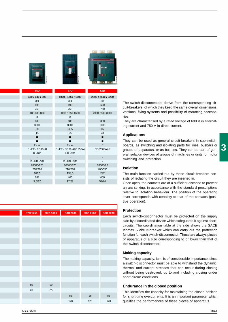
3/41ABB SACE
3
S6D
400 / 630 / 800
3/4
690
750
400-630-800
8
800
3000
30
15
F - W
F - EF - FC CuAl
R - RC
-
F - HR - VR
20000/120
210/280
103,5
268
9,5/12
S7D
1000 / 1250 / 1600
3/4
690
750
1000-1250-1600
8
800
3000
52,5
25
F - W
F - EF - FC CuAl (1250A)
HR - VR
-
F - HR - VR
10000/120
210/280
138,5
406
17/22
S8D
2000 / 2500 / 3200
3/4
690
750
2000-2500-3200
8
800
3000
85
40
F
EF (2500A)-R
-
-
10000/20
406/556
242
400
57/76
GS
IS91
44
GS
IS91
45
GS
IS91
46
S7D 1250 S7D 1600 S8D 2000 S8D 2500 S8D 3200
50 50
65 65
85 85 85
120 120 120
The switch-disconnectors derive from the corresponding cir-cuit-breakers, of which they keep the same overall dimensions,versions, fixing systems and possibility of mounting accesso-ries.They are characterised by a rated voltage of 690 V in alternat-ing current and 750 V in direct current.
Applications
They can be used as general circuit-breakers in sub-switch-boards, as switching and isolating parts for lines, busbars orgroups of apparatus, or as bus-ties. They can be part of gen-eral isolation devices of groups of machines or units for motorswitching and protection.
Isolation
The main function carried out by these circuit-breakers con-sists of isolating the circuit they are inserted in.Once open, the contacts are at a sufficient distance to preventan arc striking, in accordance with the standard prescriptionsrelative to isolation behaviour. The position of the operatinglever corresponds with certainty to that of the contacts (posi-tive operation).
Protection
Each switch-disconnector must be protected on the supplyside by a coordinated device which safeguards it against short-circuits. The coordination table at the side shows the SACEIsomax S circuit-breaker which can carry out the protectionfunction for each switch-disconnector. These are always piecesof apparatus of a size corresponding to or lower than that ofthe switch-disconnector.
Making capacity
The making capacity, Icm, is of considerable importance, sincea switch-disconnector must be able to withstand the dynamic,thermal and current stresses that can occur during closingwithout being destroyed, up to and including closing undershort-circuit conditions.
Endurance in the closed positionThis identifies the capacity for maintaining the closed positionfor short-time overcurrents. It is an important parameter whichqualifies the performances of these pieces of apparatus.

3/42 ABB SACE

3/43
3
GS
IS90
68
SACE Isomax S quality to conquer “New worlds”
480/600 V • 100-2500 A • 25-100 kA (480V)
SACE Isomax S circuit-breakersaccording to UL489 andCSA C22.2 Standards

3/44 ABB SACE
3
Circuit-breaker type S1 S3 150 S3 225
Maximum frame continuous current 40 °C [A] 100 150 225
Number of poles Nr. 3 2 - 3 2 - 3
Rated operational voltage (AC) 50-60 Hz [V] 277/480 600 240 (B); 480 (N/H/L)
(DC) [V] 600 500
Test voltage (1min.) 50-60 Hz [V] 3000 3000 3000
UL/CSA short-circuit interrupting capacity [kA rms] N N H L B N H L
240 V AC [kA rms] 50 65 100 150 150 65 100 150
480 V AC [kA rms] 14 (R15) 65 (R15, R30)
20 (R20-R100) 25 50 85 - 25 50 65
600 V AC [kA rms] - 14 14 25 - - - -
500 V DC (2 poles in series)[kA rms] - 35 50 65 50 20 35 50
600 V DC (3 poles in series) [kA rms] - 20 35 50 - - - -
Overcurrent trip relays
Thermal-magnetic
Microprocessor based - - -
Interchangeability - - -
Dimensions H [in/mm] 4,72 / 120 6,70 / 170 6,70 / 170
fixed version W [in/mm] 3,07 / 78 4,13 / 105 4,13 / 105
D [in/mm] 2,75 / 70 4,07 / 103,5 4,07 / 103,5
Mechanical duration [op./ frequency] 25000 / 240 25000 / 120 25000 /120
Weights (fixed - 3P) [lbs.] 2,42 6,75 6,75
SACE Isomax S circuit-breakers according toUL489 and CSA C22.2 StandardsElectrical and general characteristics
In the field of moulded-case circuit-breakers, complying withthe UL489 and CSA22.2 standards, the SACE Isomax S offer isenriched by the following ranges:– circuit-breakers for power distribution (fitted with
thermomagnetic or electronic releases)– circuit-breakers with magnetic only releases for motor pro-
tection (Motor Control Protection – MCP)– switch-disconnectors for use as isolators or switching de-
vices for lines, busbars or parts of a plant circuit-breakers(Moulded Case Switch – MCS).
The SACE Isomax S offer in compliance with UL/CSA Stand-ards is completed with the introduction of three new sizes. Thereare therefore increasing possibilities for those customers whoalso operate on markets subject to the standards defined in theUL/CSA Standards, with a whole range of moulded-case cir-cuit-breakers available, with rated currents which go from 100Ato 2500A and breaking capacities, at 480 V AC, which canreach 100kA.Apart from lowering the range of rated currents, introduction of
the S1 size allows all those applications typical of power sub-distribution where a circuit-breaker characterised by limiteddimensions, but guaranteeing great versatility of application ofaccessories and installation, is particularly convenient.They further increase the possibility of selection, thanks to theintroduction of the new rating for S3, Iu=225A, with three levelsof breaking capacity (N/H/L), up to service voltage values ofUe=480V AC and 500 V DC.Finally, the S8 circuit-breaker according to the UL/CSA Stand-ard also allows completion towards higher rated currents.Isomax S8V 1600, 2000 and 2500 are suited to installationimmediately to the load side of power supply sources of lowvoltage systems and can operate safely under the most severeservice conditions required by modern installations. Their highperformances, great flexibility in mounting accessories, simplecoordination with the devices on the load side and the possibil-ity of limiting the depth of the switchboards thanks to their com-pact overall dimensions, make Isomax S8 a particularly advan-tageous choice.
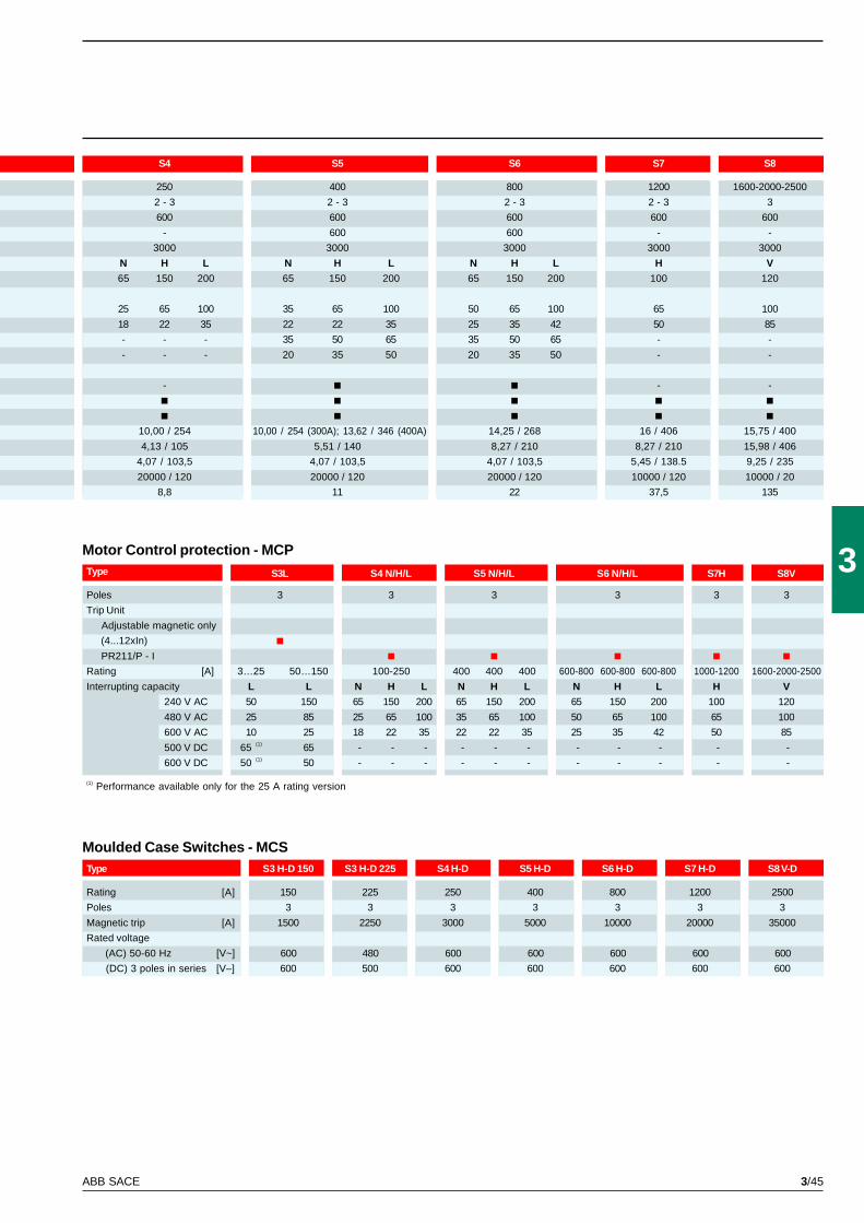
3/45ABB SACE
3Motor Control protection - MCPType S3L S4 N/H/L S5 N/H/L S6 N/H/L S7H S8V
Poles 3 3 3 3 3 3
Trip Unit
Adjustable magnetic only
(4...12xIn)
PR211/P - I
Rating [A] 3…25 50…150 100-250 400 400 400 600-800 600-800 600-800 1000-1200 1600-2000-2500
Interrupting capacity L L N H L N H L N H L H V
240 V AC 50 150 65 150 200 65 150 200 65 150 200 100 120
480 V AC 25 85 25 65 100 35 65 100 50 65 100 65 100
600 V AC 10 25 18 22 35 22 22 35 25 35 42 50 85
500 V DC 65 (1) 65 - - - - - - - - - - -
600 V DC 50 (1) 50 - - - - - - - - - - -
(1) Performance available only for the 25 A rating version
Moulded Case Switches - MCSType S3 H-D 150 S3 H-D 225 S4 H-D S5 H-D S6 H-D S7 H-D S8 V-D
Rating [A] 150 225 250 400 800 1200 2500
Poles 3 3 3 3 3 3 3
Magnetic trip [A] 1500 2250 3000 5000 10000 20000 35000
Rated voltage
(AC) 50-60 Hz [V~] 600 480 600 600 600 600 600
(DC) 3 poles in series [V–] 600 500 600 600 600 600 600
S4 S5 S6 S7 S8
250 400 800 1200 1600-2000-2500
2 - 3 2 - 3 2 - 3 2 - 3 3
600 600 600 600 600
- 600 600 - -
3000 3000 3000 3000 3000
N H L N H L N H L H V
65 150 200 65 150 200 65 150 200 100 120
25 65 100 35 65 100 50 65 100 65 100
18 22 35 22 22 35 25 35 42 50 85
- - - 35 50 65 35 50 65 - -
- - - 20 35 50 20 35 50 - -
- - -
10,00 / 254 10,00 / 254 (300A); 13,62 / 346 (400A) 14,25 / 268 16 / 406 15,75 / 400
4,13 / 105 5,51 / 140 8,27 / 210 8,27 / 210 15,98 / 406
4,07 / 103,5 4,07 / 103,5 4,07 / 103,5 5,45 / 138.5 9,25 / 235
20000 / 120 20000 / 120 20000 / 120 10000 / 120 10000 / 20
8,8 11 22 37,5 135

3/46 ABB SACE
4/1ABB SACE
4
Index
Versions ............................................................................................................................. 4/3
Connection terminals ..................................................................................................... 4/6
Service releases ............................................................................................................... 4/10
Electric signals ................................................................................................................. 4/14
Remote controls .............................................................................................................. 4/17
Operating mechanisms and locks ................................................................................ 4/22
Residual current releases ............................................................................................... 4/26
Accessories for electronic releases .............................................................................. 4/30
Installation accessories and spare parts ..................................................................... 4/35
Accessories
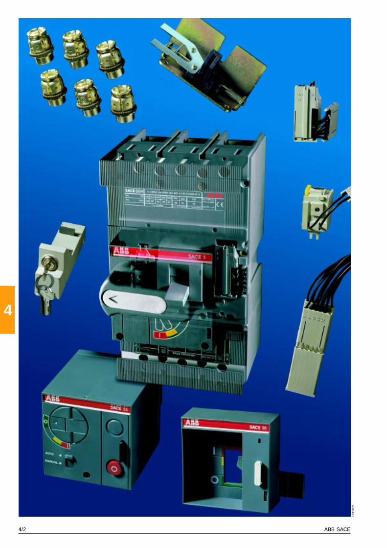
4/2 ABB SACE
4
GS
IS90
70
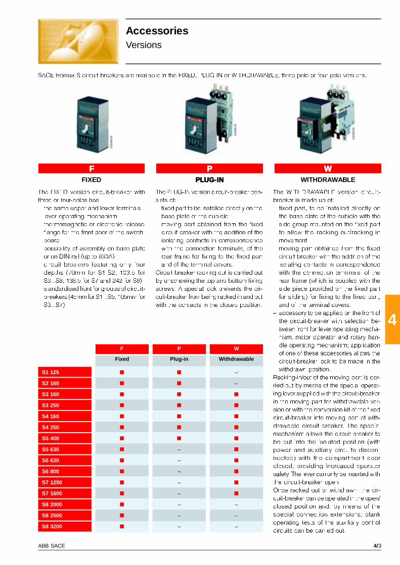
4/3ABB SACE
4
GS
IS91
20
GS
IS91
21
GS
IS91
22F P W
S1 125 –
S2 160 –
S3 160
S3 250
S4 160
S4 250
S5 400
S5 630 –
S6 630 –
S6 800 –
S7 1250 –
S7 1600 –
S8 2000 – –
S8 2500 – –
S8 3200 – –
FFFFF PPPPP WWWWW
AccessoriesVersions
SACE Isomax S circuit-breakers are available in the FIXED, PLUG-IN or WITHDRAWABLE, three-pole or four-pole versions.
The WITHDRAWABLE version circuit-
breaker is made up of:
� fixed part, to be installed directly on
the base plate of the cubicle with the
side group mounted on the fixed part
to allow the racking-out/racking-in
movement
� moving part obtained from the fixed
circuit-breaker with the addition of the
isolating contacts in correspondence
with the connection terminals, of the
rear frame (which is coupled with the
side piece provided on the fixed part
for sliding) for fixing to the fixed part,
and of the terminal covers.
� accessory to be applied on the front of
the circuit-breaker with selection be-
tween front for lever operating mecha-
nism, motor operator and rotary han-
dle operating mechanism; application
of one of these accessories allows the
circuit-breaker lock to be made in the
withdrawn position.
Racking-in/out of the moving part is car-
ried out by means of the special operat-
ing lever supplied with the circuit-breaker
in the moving part for withdrawable ver-
sion or with the conversion kit of the fixed
circuit-breaker into moving part of with-
drawable circuit-breaker. The special
mechanism allows the circuit-breaker to
be put into the isolated position (with
power and auxiliary circuits discon-
nected) with the compartment door
closed, providing increased operator
safety. The lever can only be inserted with
the circuit-breaker open.
Once racked out or withdrawn, the cir-
cuit-breaker can be operated in the open/
closed position and, by means of the
special connection extensions, blank
operating tests of the auxiliary control
circuits can be carried out.
The PLUG-IN version circuit-breaker con-
sists of:
� fixed part to be installed directly on the
base plate of the cubicle
� moving part obtained from the fixed
circuit-breaker with the addition of the
isolating contacts in correspondence
with the connection terminals, of the
rear frame for fixing to the fixed part
and of the terminal covers.
Circuit-breaker racking out is carried out
by unscrewing the top and bottom fixing
screws. A special lock prevents the cir-
cuit-breaker from being racked in and out
with the contacts in the closed position.
The FIXED version circuit-breaker with
three or four-poles has:
� the same upper and lower terminals
� lever operating mechanism
� thermomagnetic or electronic release
� flange for the front door of the switch-
board
� possibility of assembly on base plate
or on DIN rail (up to 630A)
� circuit-breakers featuring only four
depths (70mm for S1-S2, 103.5 for
S3...S6, 138.5 for S7 and 242 for S8)
� standardised front for groups of circuit-
breakers (45mm for S1...S5, 105mm for
S3...S7).
FIXED PLUG-INPLUG-INPLUG-INPLUG-INPLUG-IN WITHDRAWABLE
Fixed Plug-in Withdrawable
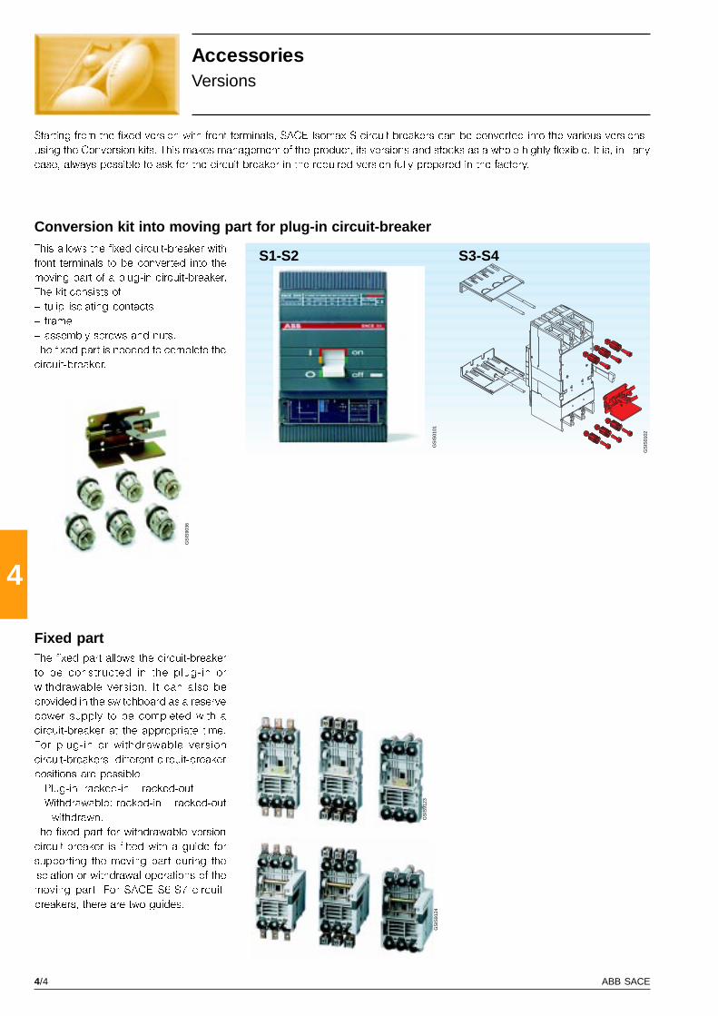
4/4 ABB SACE
4
GS
IS90
36
GS
IS91
23
GS
IS91
24
S3-S4
GS
IS01
01
GS
IS01
02
S1-S2
AccessoriesVersions
Starting from the fixed version with front terminals, SACE Isomax S circuit-breakers can be converted into the various versions
using the Conversion kits. This makes management of the product, its versions and stocks as a whole highly flexible. It is, in any
case, always possible to ask for the circuit-breaker in the required version fully prepared in the factory.
Fixed partThe fixed part allows the circuit-breaker
to be constructed in the plug-in or
withdrawable version. It can also be
provided in the switchboard as a reserve
power supply to be completed with a
circuit-breaker at the appropriate time.
For plug-in or withdrawable version
circuit-breakers, different circuit-breaker
positions are possible:
� Plug-in: racked-in � racked-out
� Withdrawable: racked-in � racked-out
- withdrawn.
The fixed part for withdrawable version
circuit-breaker is fitted with a guide for
supporting the moving part during the
isolation or withdrawal operations of the
moving part. For SACE S6-S7 circuit-
breakers, there are two guides.
Conversion kit into moving part for plug-in circuit-breakerThis allows the fixed circuit-breaker with
front terminals to be converted into the
moving part of a plug-in circuit-breaker.
The kit consists of:
� tulip isolating contacts
� frame
� assembly screws and nuts.
The fixed part is needed to complete the
circuit-breaker.
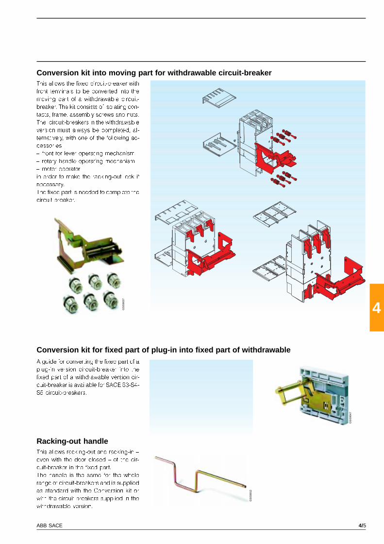
4/5ABB SACE
4GS
IS90
37
GS
IS90
47
GS
IS90
12
Racking-out handleThis allows racking-out and racking-in �
even with the door closed � of the cir-
cuit-breaker in the fixed part.
The handle is the same for the whole
range of circuit-breakers and is supplied
as standard with the Conversion kit or
with the circuit-breakers supplied in the
withdrawable version.
Conversion kit into moving part for withdrawable circuit-breakerThis allows the fixed circuit-breaker with
front terminals to be converted into the
moving part of a withdrawable circuit-
breaker. The kit consists of isolating con-
tacts, frame, assembly screws and nuts.
The circuit-breakers in the withdrawable
version must always be completed, al-
ternatively, with one of the following ac-
cessories:
� front for lever operating mechanism
� rotary handle operating mechanism
� motor operator,
in order to make the racking-out lock if
necessary.
The fixed part is needed to complete the
circuit-breaker.
Conversion kit for fixed part of plug-in into fixed part of withdrawableA guide for converting the fixed part of a
plug-in version circuit-breaker into the
fixed part of a withdrawable version cir-
cuit-breaker is available for SACE S3-S4-
S5 circuit-breakers.
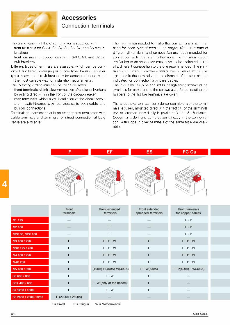
4/6 ABB SACE
4
F EF ES FC Cu
GS
IS00
86
GS
IS00
87
GS
IS00
88
GS
IS00
89
S1 125
S2 160
S2X 80, S2X 100
S3 160 / 250
S3X 125 / 200
S4 160 / 250
S4X 250
S5 400 / 630
S6 630 / 800
S6X 400 / 630
S7 1250 / 1600
S8 2000 / 2500 / 3200
AccessoriesConnection terminals
The basic version of the circuit-breaker is supplied with:
� front terminals for SACE S3, S4, S5, S6, S7, and S8 circuit-
breakers
� front terminals for copper cables for SACE S1, and S2 cir-
cuit-breakers.
Different types of terminals are available, which can be com-
bined in different ways (upper of one type, lower of another
type), allows the circuit-breaker to be connected to the plant
in the most suitable way for installation requirements.
The following distinctions can be made between:
� front terminals which allow connection of cables or busbars
by acting directly from the front of the circuit-breaker.
� rear terminals which allow installation of the circuit-break-
ers in switchboards with rear access to both cable and
busbar connections.
Terminals for connection of busbars or cables terminated with
cable terminals and terminals for direct connection of bare
cable are available.
The information needed to make the connections is summa-
rised for each type of terminal on pages 4/8-9. Flat bars of
different dimensions and composition are recommended for
connection with busbars. Furthermore, the minimum depth
the flat bar to be connected must have is also indicated, if it is
of a different composition to the one recommended. The mini-
mum and maximum cross-section of the cables which can be
tightened in the terminals and the diameter of the terminal are
indicated for connection with bare cables
The torque values to be applied to the tightening screws of the
terminals for cable and to the screws used for connecting the
busbars to the flat bar terminals are given.
The circuit-breakers can be ordered complete with the termi-
nals required, mounted directly in the factory, or the terminals
can be ordered individually in packs of 3 - 4 - 6 - 8 pieces.
Codes for ordering circuit-breakers directly in the configura-
tion with upper / lower terminals of the same type are avail-
able.
F = Fixed P = Plug-in W = Withdrawable
Front Front extended Front extended Front terminalsterminals terminals spreaded terminals for copper cables
— — — F - P
— F — F - P
— F — F - P
F F - P - W F F - P - W
F F - P - W F F - P - W
F F - P - W F F - P - W
F F - P - W F F - P - W
F F(400A)-P(400A)-W(400A) F - W(630A) F - P(400A) - W(400A)
F F - W F —
F F - W (only at the bottom) F —
F F - W F —
F (2000A / 2500A) — — —
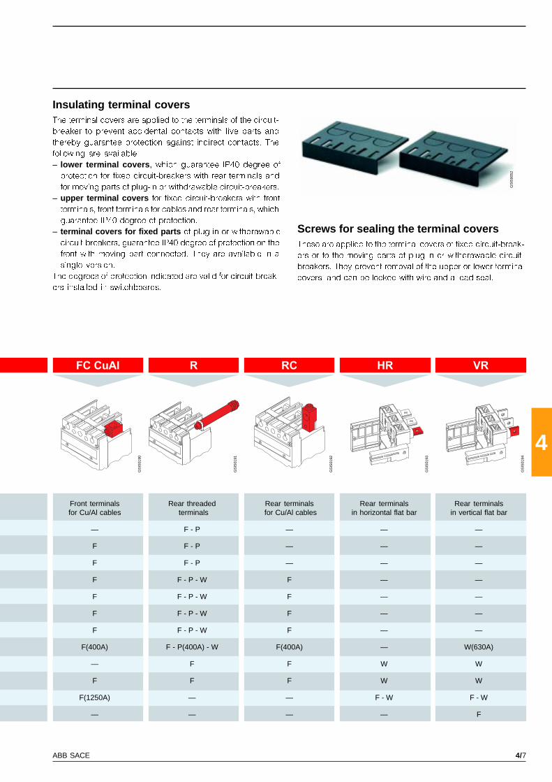
4/7ABB SACE
4
FC CuAl R RC HR VR
GS
IS90
52
GS
IS01
90
GS
IS01
91
GS
IS01
92
GS
IS01
93
GS
IS01
94
Insulating terminal coversThe terminal covers are applied to the terminals of the circuit-
breaker to prevent accidental contacts with live parts and
thereby guarantee protection against indirect contacts. The
following are available:
– lower terminal covers , which guarantee IP40 degree of
protection for fixed circuit-breakers with rear terminals and
for moving parts of plug-in or withdrawable circuit-breakers.
– upper terminal covers for fixed circuit-breakers with front
terminals, front terminals for cables and rear terminals, which
guarantee IP40 degree of protection.
– terminal covers for fixed parts of plug-in or withdrawable
circuit-breakers, guarantee IP40 degree of protection on the
front with moving part connected. They are available in a
single version.
The degrees of protection indicated are valid for circuit-break-
ers installed in switchboards.
Screws for sealing the terminal coversThese are applied to the terminal covers of fixed circuit-break-
ers or to the moving parts of plug-in or withdrawable circuit-
breakers. They prevent removal of the upper or lower terminal
covers, and can be locked with wire and a lead seal.
Front terminals Rear threaded Rear terminals Rear terminals Rear terminalsfor Cu/Al cables terminals for Cu/Al cables in horizontal flat bar in vertical flat bar
— F - P — — —
F F - P — — —
F F - P — — —
F F - P - W F — —
F F - P - W F — —
F F - P - W F — —
F F - P - W F — —
F(400A) F - P(400A) - W F(400A) — W(630A)
— F F W W
F F F W W
F(1250A) — — F - W F - W
— — — — F

4/8 ABB SACE
4
S3 160, S3X 125 F 1 20 10 4 9 9 R R
S3 250, S3X 200 F 1 20 10 6 9 9 R R
S4 160 F 1 20 10 4 9 9 R R
S4 250, S4X 250 F 1 20 10 6 9 9 R R
S5 400 F 2 25 12 5 11 18 R R
S5 630 F 2 25 12 8 11 18 R R
S6 630,S6X 400-630 F 2 40 12 5 2 x 7 9 R R
S6 800 F 2 50 12 5 2 x 7 9 R R
S7 1250 F 2 50 20 8 2 x 11 18 R
S7 1600 F 2 50 20 10 2 x 11 18 R
S8 2000 F 3 100 5 4 x 15 70 (2) R
S8 2500 F 4 100 5 4 x 15 70 (2)
S2 160 F 1 20 4 8 20 8 5 9 R R
S3 160, S3X 125 F-P-W 1 20 4 8.5 20 8.5 9 9 R R R
S3 250, S3X 200 F-P-W 1 20 6 8.5 20 8.5 9 9 R R R
S4 160 F-P-W 1 20 4 8.5 20 8.5 9 9 R R R
S4 250, S4X 250 F-P-W 1 20 6 8.5 20 8.5 9 9 R R R
S5 400 F-P-W 2 25 5 11 25 11 18 18 R R R
S6 630,S6X 400-630 F-W 2 40 5 11 40 11 9 18 R
S6 800 F-W 2 50 5 14 50 14 9 30 R
S7 1250 F-W 2 50 8 4x11(4) 45 18 R
S7 1600 F-W 2 50 10 4x11(4) 45 18 R
S1 125 F-P 1 1.5...50 max.10 max.10 2.5-5 (1) 11 R R
S2 160 F-P 1 1.5...70 max.12 max.12 2.5-5 (1) 12.5 R R
S3 160, S3X 125 F-P-W 1 6...185 16 18 R R S
S3 250, S3X 200 F-P-W 1 6...185 16 18 R R S
S4 160 F-P-W 1 6...185 16 18 R R S
S4 250, S4X 250 F-P-W 1 6...185 16 18 R R S
S5 400 F-P-W 1 16...240 25 24 R R S
S5 630 F-W 2 50...185 31 20 S
S3 F 1 30 4 8.5 30 8.5 9 9 S
S4 F 1 30 4 8.5 30 8.5 9 9 S
S5 400 F 2 40 5 11 40 11 18 18 S
S5 630 F-W 2 40 5 11 40 11 18 18 S
S6 F 2 50 5 3 x 13 4 x 45 13 9 30
S7 1600 F 2 50 10 3 x 13 4 x 45 13 45 20
S3-S4-S5
S3-S4-S5 S6 630
S6 800 S7
S3-S4-S5
S6 S7
S1-S2
S2
S3-S4-S5 S6
S7
PF S3-S4-S5
PF S5 630
PF S6
PF S7
GS
IS00
95
Key
(1) Tightening torque of 2.5 Nm for < 10 mm2
cable cross-section(2) M12 class 8.8 screws(3) M16 class 8.8 screws(4) Only use two holes diagonally
A = Tightening of the terminal onto the circuit-breakerB = Tightening the cable/busbar or cable terminal onto
the terminalR = On requestS = Standard
Front terminalsThese allow busbars or cables terminated with a cable terminal to be connected
Type version pieces busbars [mm] tightening terminal coversL H P hole B [Nm] upper lower fixed part
Front extended terminalsThese allow busbars or cables terminated with a cable terminal to be connected
Type version pieces busbars [mm] cable term. [mm] tightening [Nm] terminal coversL P hole L hole A B upper lower fixed p.
Front terminals for copper cablesThese allow bare copper cables to be connected directly to the circuit-breaker. They are not
suitable for tube cable terminals
Type version pieces cable busbars cable term. tightening Ø clamps terminal covers[mm2] L [mm] L [mm] B [Nm] [mm] upper lower fixed p.
Front extended spreaded terminalsThese allow busbars or cables terminated with a cable terminal to be connected
Type version pieces busbars [mm] cable term. [mm] tightening [Nm] terminal coversL P hole L hole A B upper lower fixed p.
AccessoriesConnection terminals
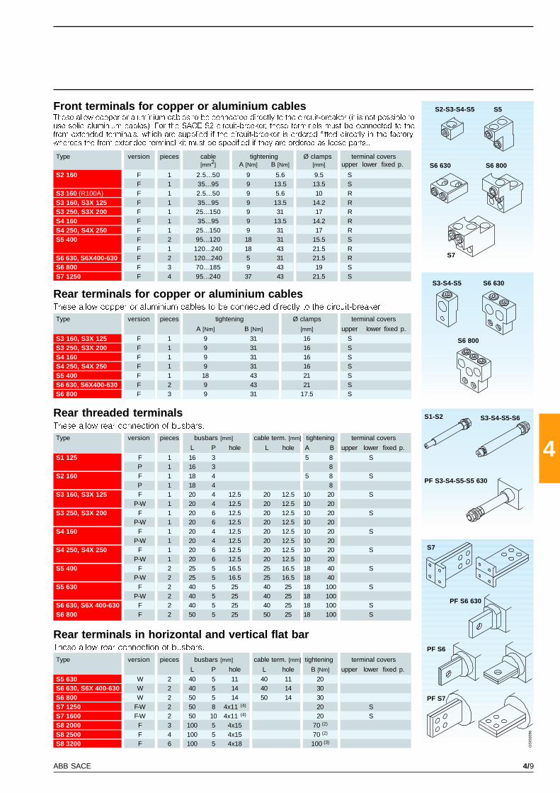
4/9ABB SACE
4S1 125 F 1 16 3 5 8 SP 1 16 3 8
S2 160 F 1 18 4 5 8 SP 1 18 4 8
S3 160, S3X 125 F 1 20 4 12.5 20 12.5 10 20 SP-W 1 20 4 12.5 20 12.5 10 20
S3 250, S3X 200 F 1 20 6 12.5 20 12.5 10 20 SP-W 1 20 6 12.5 20 12.5 10 20
S4 160 F 1 20 4 12.5 20 12.5 10 20 SP-W 1 20 4 12.5 20 12.5 10 20
S4 250, S4X 250 F 1 20 6 12.5 20 12.5 10 20 SP-W 1 20 6 12.5 20 12.5 10 20
S5 400 F 2 25 5 16.5 25 16.5 18 40 SP-W 2 25 5 16.5 25 16.5 18 40
S5 630 F 2 40 5 25 40 25 18 100 SP-W 2 40 5 25 40 25 18 100
S6 630, S6X 400-630 F 2 40 5 25 40 25 18 100 SS6 800 F 2 50 5 25 50 25 18 100 S
S5 630 W 2 40 5 11 40 11 20S6 630, S6X 400-630 W 2 40 5 14 40 14 30S6 800 W 2 50 5 14 50 14 30S7 1250 F-W 2 50 8 4x11 (4) 20 SS7 1600 F-W 2 50 10 4x11 (4) 20 SS8 2000 F 3 100 5 4x15 70 (2)
S8 2500 F 4 100 5 4x15 70 (2)
S8 3200 F 6 100 5 4x18 100 (3)
S3 160, S3X 125 F 1 9 31 16 SS3 250, S3X 200 F 1 9 31 16 SS4 160 F 1 9 31 16 SS4 250, S4X 250 F 1 9 31 16 SS5 400 F 1 18 43 21 SS6 630, S6X400-630 F 2 9 43 21 SS6 800 F 3 9 31 17.5 S
S2 160 F 1 2.5...50 9 5.6 9.5 SF 1 35...95 9 13.5 13.5 S
S3 160 (R100A) F 1 2.5...50 9 5.6 10 RS3 160, S3X 125 F 1 35...95 9 13.5 14.2 RS3 250, S3X 200 F 1 25...150 9 31 17 RS4 160 F 1 35...95 9 13.5 14.2 RS4 250, S4X 250 F 1 25...150 9 31 17 RS5 400 F 2 95...120 18 31 15.5 S
F 1 120...240 18 43 21.5 RS6 630, S6X400-630 F 2 120...240 5 31 21.5 RS6 800 F 3 70...185 9 43 19 SS7 1250 F 4 95...240 37 43 21.5 S
S7
S2-S3-S4-S5 S5
S6 630 S6 800
S7
S3-S4-S5 S6 630
S6 800
S3-S4-S5-S6S1-S2
PF S6 630
PF S7
PF S6
PF S3-S4-S5-S5 630
GS
IS00
96
Rear terminals for copper or aluminium cablesThese allow copper or aluminium cables to be connected directly to the circuit-breaker.
Type version pieces tightening Ø clamps terminal covers
A [Nm] B [Nm] [mm] upper lower fixed p.
Rear terminals in horizontal and vertical flat barThese allow rear connection of busbars.
Type version pieces busbars [mm] cable term. [mm] tightening terminal covers
L P hole L hole B [Nm] upper lower fixed p.
Front terminals for copper or aluminium cablesThese allow copper or aluminium cables to be connected directly to the circuit-breaker (it is not possible touse solid aluminium cables). For the SACE S2 circuit-breaker, these terminals must be connected to thefront extended terminals, which are supplied if the circuit-breaker is ordered fitted directly in the factory,whereas the front extended terminal kit must be specified if they are ordered as loose parts..
Type version pieces cable tightening Ø clamps terminal covers[mm2] A [Nm] B [Nm] [mm] upper lower fixed p.
Rear threaded terminalsThese allow rear connection of busbars.
Type version pieces busbars [mm] cable term. [mm] tightening terminal covers
L P hole L hole A B upper lower fixed p.

4/10 ABB SACE
4
S1-S2 S3-S4-S5
S6-S7 S8
(*)
GS
IS90
01
GS
IS01
07
GS
IS01
08
GS
IS01
09
GS
IS01
10
S3-S4 S5 S6-S7
S1 - S2 S3 -S4 - S5 S6 - S7 S8
50-60 Hz DC 50-60 Hz DC 50-60 Hz DC 50-60 Hz DC
[V~] [V–] [V~] [V–] [V~] [V–] [V~] [V–]
24 … 30 12 12 24
48 60 24 24 24 24 24 30
100 … 130 48 48 48 48 48 48
220 … 250 60 60 ... 72 60 60 60
380 … 440 110 … 120 110 … 125 110 … 120 110 … 125 100 ... 127 100 ... 27
24 220 … 240 220 … 250 220 … 240 220 … 250 127 ... 150
48 380 … 400 380 … 400 150 ... 180 160
110 480 480 200 ... 255 200 ... 250
220 380 ... 500
250
S1...S5 S6...S7 S8
AC DC AC DC AC DC
[VA] [W] [VA] [W] [VA] [W]
100 120 150 150 200 150
S3 S4...S7 S8
[ms] [ms] [ms]
< 15 < 15 < 20 10000 7500 2500
AccessoriesService releases
Shunt opening releaseThis allows circuit-breaker opening by
means of an electric command. Release
operation is guaranteed for a voltage
between 70% and 110% of the rated
power supply voltage Un, both in AC and
in DC. It is always fitted with an auxiliary
limit contact.
The service releases, shunt opening and undervoltage releases, housed and fixed in a slot in the left part of the circuit-break er
are always alternative to each other. The power supply is made by means of special connectors for sizes S3 to S7, whereas for
S1-S2, it is made by means of free wires 0.6 m long or with plug-socket connectors which can be supplied on request.
Assembly is carried out by pressure into the appropriate housing in the left part of the circuit-breaker.
(*) For the SACE S1-S2 circuit-breakers , the service releases are fixed to the circuit-breaker cover
Power supply voltages
Powers absorbedon inrush
Circuit-breakeropening times
Number ofoperations
[nr.] [nr.] [nr.]
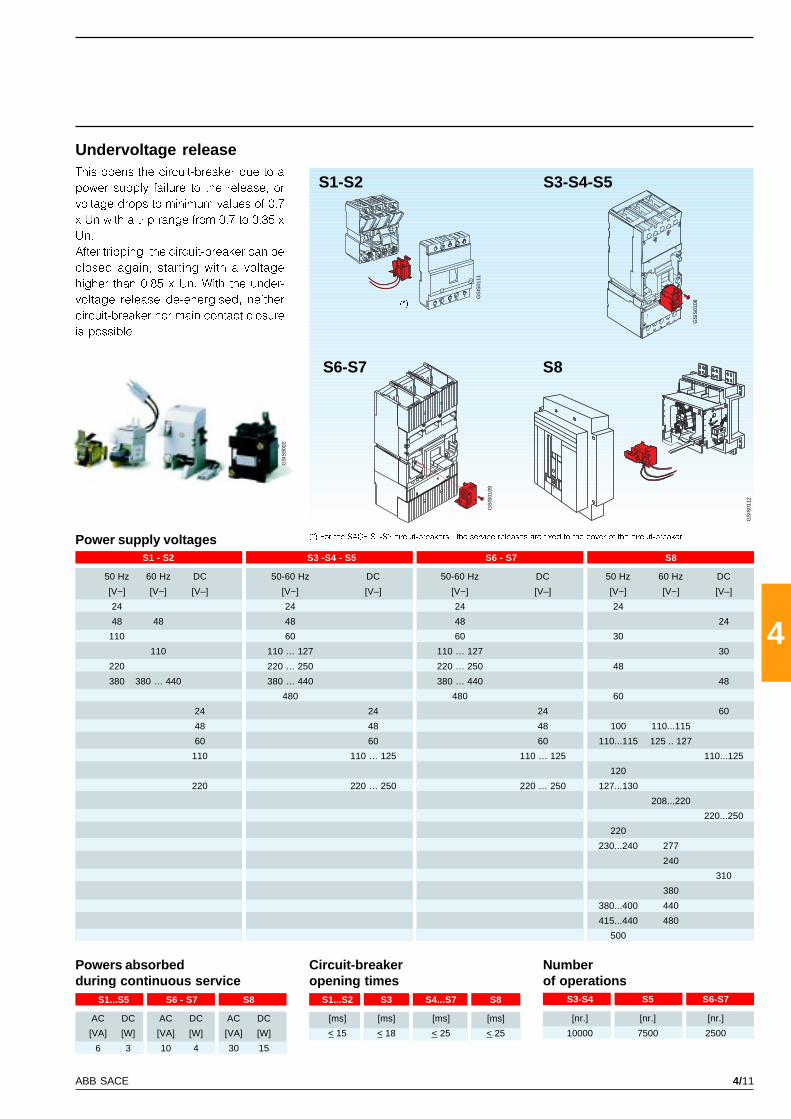
4/11ABB SACE
4
S1-S2 S3-S4-S5
S6-S7 S8
(*)
GS
IS90
02
GS
IS01
11
GS
IS01
08
GS
IS01
09
GS
IS01
12
S3-S4 S5 S6-S7
S1 - S2 S3 -S4 - S5 S6 - S7 S8
50 Hz 60 Hz DC 50-60 Hz DC 50-60 Hz DC 50 Hz 60 Hz DC
[V~] [V~] [V–] [V~] [V–] [V~] [V–] [V~] [V~] [V–]
24 24 24 24
48 48 48 48 24
110 60 60 30
110 110 … 127 110 … 127 30
220 220 … 250 220 … 250 48
380 380 … 440 380 … 440 380 … 440 48
480 480 60
24 24 24 60
48 48 48 100 110...115
60 60 60 110...115 125 .. 127
110 110 … 125 110 … 125 110...125
120
220 220 … 250 220 … 250 127...130
208...220
220...250
220
230...240 277
240
310
380
380...400 440
415...440 480
500
10000 7500 2500
S1...S2 S3 S4...S7 S8
[ms] [ms] [ms] [ms]
< 15 < 18 < 25 < 25
S1...S5 S6 - S7 S8
AC DC AC DC AC DC
[VA] [W] [VA] [W] [VA] [W]
6 3 10 4 30 15
This opens the circuit-breaker due to a
power supply failure to the release, or
voltage drops to minimum values of 0.7
x Un with a trip range from 0.7 to 0.35 x
Un.
After tripping, the circuit-breaker can be
closed again, starting with a voltage
higher than 0.85 x Un. With the under-
voltage release de-energised, neither
circuit-breaker nor main contact closure
is possible.
Undervoltage release
(*) For the SACE S1-S2 circuit-breakers , the service releases are fixed to the cover of the circuit-breakerPower supply voltages
Numberof operations
[nr.] [nr.] [nr.]
Circuit-breakeropening times
Powers absorbedduring continuous service
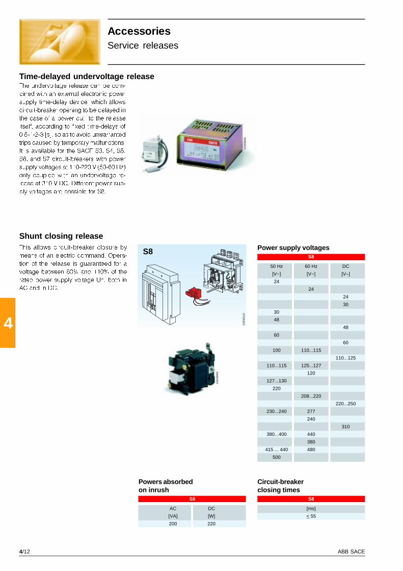
4/12 ABB SACE
4
GS
IS90
42
GS
IS90
03
S8G
SIS
0112
S8
50 Hz 60 Hz DC
[V~] [V~] [V–]
24
24
24
30
30
48
48
60
60
100 110...115
110...125
110...115 125...127
120
127...130
220
208...220
220...250
230...240 277
240
310
380...400 440
380
415 ... 440 480
500
S8
[ms]
< 55
S8
AC DC
[VA] [W]
200 220
AccessoriesService releases
Time-delayed undervoltage releaseThe undervoltage release can be com-
bined with an external electronic power
supply time-delay device, which allows
circuit-breaker opening to be delayed in
the case of a power cut to the release
itself, according to fixed time-delays of
0.5-1-2-3 [s], so as to avoid unwarranted
trips caused by temporary malfunctions.
It is available for the SACE S3, S4, S5,
S6, and S7 circuit-breakers with power
supply voltages at 110-220 V (50-60 Hz)
only coupled with an undervoltage re-
lease at 310 V DC. Different power sup-
ply voltages are possible for S8.
Shunt closing releaseThis allows circuit-breaker closure by
means of an electric command. Opera-
tion of the release is guaranteed for a
voltage between 80% and 110% of the
rated power supply voltage Un, both in
AC and in DC.
Power supply voltages
Circuit-breakerclosing times
Powers absorbedon inrush
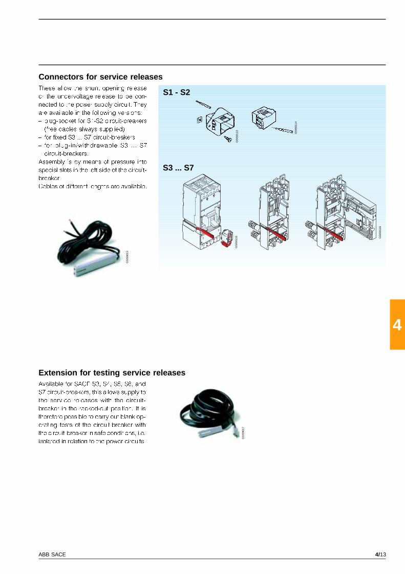
4/13ABB SACE
4
GS
IS90
13
GS
IS90
17
S1 - S2
S3 ... S7
GS
IS01
15G
SIS
0113 GS
IS01
14
GS
IS01
16
Extension for testing service releasesAvailable for SACE S3, S4, S5, S6, and
S7 circuit-breakers, this allows supply to
the service releases with the circuit-
breaker in the racked-out position. It is
therefore possible to carry out blank op-
erating tests of the circuit-breaker with
the circuit-breaker in safe conditions, i.e.
isolated in relation to the power circuits.
Connectors for service releasesThese allow the shunt opening release
or the undervoltage release to be con-
nected to the power supply circuit. They
are available in the following versions:
� plug-socket for S1-S2 circuit-breakers
(free cables always supplied)
� for fixed S3 ... S7 circuit-breakers
� for plug-in/withdrawable S3 ... S7
circuit-breakers.
Assembly is by means of pressure into
special slots in the left side of the circuit-
breaker.
Cables of different lengths are available.
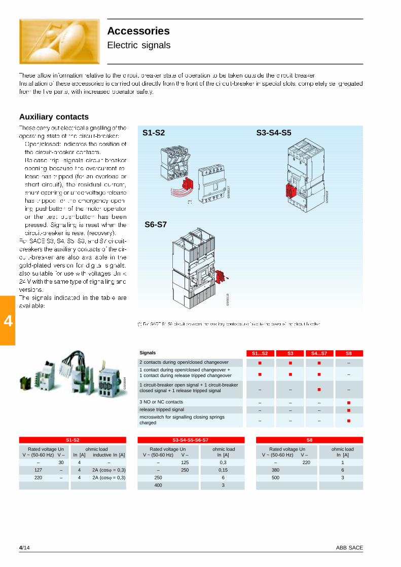
4/14 ABB SACE
4
GS
IS90
04
S1-S2 S3-S4-S5-S6-S7 S8
S1...S2 S3 S4...S7 S8
–
–
– – –
– – –
– – –
– – –
S1-S2 S3-S4-S5
S6-S7
(*)
GS
IS01
17
GS
IS01
18
GS
IS01
19
AccessoriesElectric signals
Auxiliary contactsThese carry out electrical signalling of the
operating state of the circuit-breaker:
� Open/closed: indicates the position of
the circuit-breaker contacts.
� Release trip: signals circuit-breaker
opening because the overcurrent re-
lease has tripped (for an overload or
short-circuit), the residual current,
shunt opening or undervoltage release
has tripped, or the emergency open-
ing pushbutton of the motor operator
or the test pushbutton has been
pressed. Signalling is reset when the
circuit-breaker is reset (recovery).
For SACE S3, S4, S5, S6, and S7 circuit-
breakers the auxiliary contacts of the cir-
cuit-breaker are also available in the
gold-plated version for digital signals,
also suitable for use with voltages Un <
24 V with the same type of signalling and
versions.
The signals indicated in the table are
available:
These allow information relative to the circuit-breaker state of operation to be taken outside the circuit-breaker.
Installation of these accessories is carried out directly from the front of the circuit-breaker in special slots, completely se gregated
from the live parts, with increased operator safety.
(*) For SACE S1-S2 circuit-breakers the auxiliary contacts are fixed to the cover of the circuit-breaker
Rated voltage Un ohmic loadV ~ (50-60 Hz) V – In [A] inductive In [A]
– 30 4 –
127 – 4 2A (cosj = 0,3)
220 – 4 2A (cosj = 0,3)
Rated voltage Un ohmic loadV ~ (50-60 Hz) V – In [A]
– 125 0,3
– 250 0,15
250 6
400 3
Rated voltage Un ohmic loadV ~ (50-60 Hz) V – In [A]
– 220 1
380 6
500 3
Signals
2 contacts during open/closed changeover
1 contact during open/closed changeover +1 contact during release tripped changeover
1 circuit-breaker open signal + 1 circuit-breakerclosed signal + 1 release tripped signal
3 NO or NC contacts
release tripped signal
microswitch for signalling closing springscharged
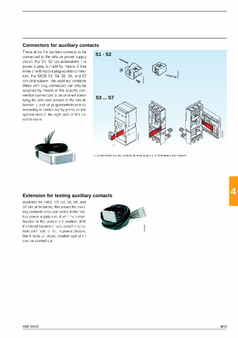
4/15ABB SACE
4
GS
IS90
15
GS
IS90
89
S1 - S2
S3 ... S7
(*)
GS
IS01
20
GS
IS01
21
GS
IS01
13 GS
IS01
14
(*) Connectors for auxiliary contacts, for fixed, plug-in or withdrawable circuit-breakers
These allow the auxiliary contacts to be
connected to the relative power supply
circuit. For S1, S2 circuit-breakers, the
power supply is made by means of free
wires or with mobile plug-socket connec-
tors. For SACE S3, S4, S5, S6, and S7
circuit-breakers, the auxiliary contacts
(fitted with plug connector) can only be
supplied by means of the specific con-
nection connectors to be ordered speci-
fying the size and version of the circuit-
breaker (fixed or plug-in/withdrawable).
Assembly is carried out by pressure into
special slots in the right side of the cir-
cuit-breaker.
Extension for testing auxiliary contactsAvailable for SACE S3, S4, S5, S6, and
S7 circuit-breakers, this allows the auxil-
iary contacts to be connected to the rela-
tive power supply circuit with the circuit-
breaker in the racked-out position. With
the circuit-breaker in safe conditions, i.e.
isolated in relation to the power circuits,
blank tests of circuit-breaker operation
can be carried out.
Connectors for auxiliary contacts

4/16 ABB SACE
4
GS
IS90
38
GS
IS90
06
S2 S3-S4-S5-S6-S7
S3 ... S7
GS
IS01
60
S3 ... S7
GS
IS01
22
GS
IS01
23
AccessoriesElectric signals
Circuit-breaker position contactsFor the fixed part of the SACE S2, S3, S4,
S5, S6, and S7 circuit-breakers, these
carry out electrical position signalling of
the circuit-breaker in relation to the fixed
part: racked-in, racked-out. They can
only be connected by means of free wires
and are available in the following ver-
sions:
� Contacts for signalling circuit-breaker
racked in
� Contacts for signalling circuit-breaker
racked out.
A maximum of three contacts for S2, two
contacts for S3, three contacts for S4-S5
and five contacts for S6-S7 can be in-
stalled on the fixed part, in any combi-
nation.
The circuit-breaker position contacts are
also available in the gold-plated version
for digital signals also suitable for use
with voltages Un < 24 V with the same
type of signals and combinations.
Early auxiliary contact for undervoltage releaseThe early auxiliary contact for the under-
voltage release, interlocked with the ro-
tary handle operating mechanism, keeps
the release de-energised with the circuit-
breaker open.
It is supplied complete with socket con-
nector of the type with double slide for
simultaneous connection of the under-
voltage release and the accept contact.
Rated voltage Un ohmic loadV ~ (50-60 Hz) V – In [A] inductive In [A]
– 30 4 –
127 – 4 2A (cosj = 0,3)
220 – 4 2A (cosj = 0,3)
Rated voltage Un ohmic loadV ~ (50-60 Hz) V – In [A]
– 125 0,3
– 250 0,15
250 6
400 3

4/17ABB SACE
4
GS
IS90
22
GS
IS90
23
GS
IS01
25
S1-S2
GS
IS01
24
Solenoid operating mechanism for SACE S1-S2circuit-breakersThis operates both opening and closing
of the circuit-breaker, acting directly on
its lever.
There are two versions available, one
placed �beside� the circuit-breaker (for
installation on a panel or DIN EN 50022
rail), the other on the �front�, suitable for
being installed directly on the front of the
circuit-breaker.
Both versions can be used either for S1
or for S2 and in the three- and four-pole
version.
These allow remote control of circuit-breaker opening and closing and are particularly suitable for use in electrical network
supervision and control systems. They are complete with manual operating lever and emergency opening pushbutton (starting
from S3). A selector allows changeover from automatic to manual operation. They are always fitted with a padlock and, on
request, can be fitted with a key lock in the open position.
AccessoriesRemote controls
Rated voltage, Un AC DC
[V] – 48
[V] 110 60
[V] 220 ... 230 110
[V] – 220
Operating voltage 85 ... 110% Un 85 ... 110% Un
Inrush power absorption, Ps 2300-2500 [VA] 700-900 [W]
Duration opening [s] < 0.1
closing [s] < 0.1
Mechanical life [no. operations] 25000
Degree of protection, on the front IP 30
Minimum duration of the openingand closing command impulse [ms] > 100
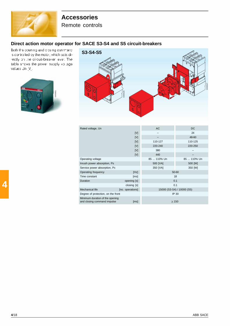
4/18 ABB SACE
4
GS
IS90
21 S3-S4-S5
GS
IS01
26
GS
IS01
27
Direct action motor operator for SACE S3-S4 and S5 circuit-breakers
AccessoriesRemote controls
Both the opening and closing command
is controlled by the motor, which acts di-
rectly on the circuit-breaker lever. The
table shows the power supply voltage
values Un [V].
Rated voltage, Un AC DC
[V] – 24
[V] – 48-60
[V] 110-127 110-125
[V] 220-240 220-250
[V] 380 –
[V] 440 –
Operating voltage 85 ... 110% Un 85 ... 110% Un
Inrush power absorption, Ps 500 [VA] 500 [W]
Service power absorption, Pc 350 [VA] 350 [W]
Operating frequency [Hz] 50-60
Time constant [ms] 18
Duration opening [s] 0.1
closing [s] 0.1
Mechanical life [no. operations] 15000 (S3-S4) / 10000 (S5)
Degree of protection, on the front IP 30
Minimum duration of the openingand closing command impulse [ms] > 150

4/19ABB SACE
4
GS
IS90
20
S6-S7
GS
IS01
28
GS
IS01
29
Stored energy motor operator for SACE S6-S7 circuit-breakers
Rated voltage, Un AC DC
[V] – 24
[V] – 48
[V] – 60
[V] 110 110
[V] 120-127 120-127
[V] 220-250 220-250
[V] 380 –
[V] – –
Operating voltage 85 ... 110% Un 85 ... 110% Un
Inrush power absorption, Ps 660 [VA] 600 [W]
Service power absorption, Pc 180 [VA] 180 [W]
Operating frequency [Hz] 50-60
Time constant [ms] 22
Duration closing 0.09
opening 1.2
resetting 2
Mechanical life [no. operations] 10000 (S6) / 5000 (S7)
Degree of protection, on the front IP 30
Minimum duration of the openingand closing command impulse [ms] > 100
With the stored energy operating mecha-
nism, during circuit-breaker opening the
release mechanism automatically pre-
charges a system of springs: the stored
energy is exploited for closing the circuit-
breaker. It is supplied complete with
shunt closing release (Ps=100VA~/
100W�) and flange for the compartment
door. The table shows the power supply
voltage values Un [V].
In the case of interlocked circuit-break-
ers, the key lock against manual opera-
tion is necessary.

4/20 ABB SACE
4
GS
IS90
07
GS
IS90
14
GS
IS90
16
S3 ... S7
S3 ... S7
GS
IS01
30
AccessoriesRemote controls
Geared motor for SACE S8 circuit-breakerThis allows the springs of the circuit-
breaker closing mechanism to be
charged automatically, immediately fol-
lowing an closing operation. It includes
a limit microswitch for electrical signal-
ling of closing springs charged.
Connectors for motor operatorsThe motor operators, from S3 to S7, can
only be supplied by means of the spe-
cific connection connectors. They are of
the slide type and allow simultaneous
connection of both the motor operator
and the auxiliary contacts to the relative
power supply circuit. They are an alter-
native to the corresponding connectors
for the auxiliary contacts only since they
are housed in the same seat. They must
be ordered specifying the size and ver-
sion of the circuit-breaker (fixed or plug-
in/withdrawable).
Extension for testing motor operatorsFor the SACE S3, S4, S5, S6, and S7 cir-
cuit-breakers, this allows both motor op-
erators and the auxiliary contacts to be
connected to the relative power supply
circuit with the circuit-breaker in the
racked-out position. With the circuit-
breaker in safe conditions, i.e. isolated
in relation to the power circuits, blank
operating tests of the circuit-breaker can
be carried out. It must be ordered speci-
fying the size and version of the circuit-
breaker (fixed or plug-in/withdrawable)
and automatically excludes the corre-
sponding extension for testing the auxil-
iary contacts
Rated voltage, Un AC DC
[V] – 24-30
[V] – 48-60
[V] 100-130 100-130
[V] 220-250 220-250
Inrush power absorption, Ps 1000 [VA] 1000 [W]
Service power absorption, Pc 230 [VA] 230 [W]
Charging time [s] 7 ... 10
Mechanical life [no. operations] 5000
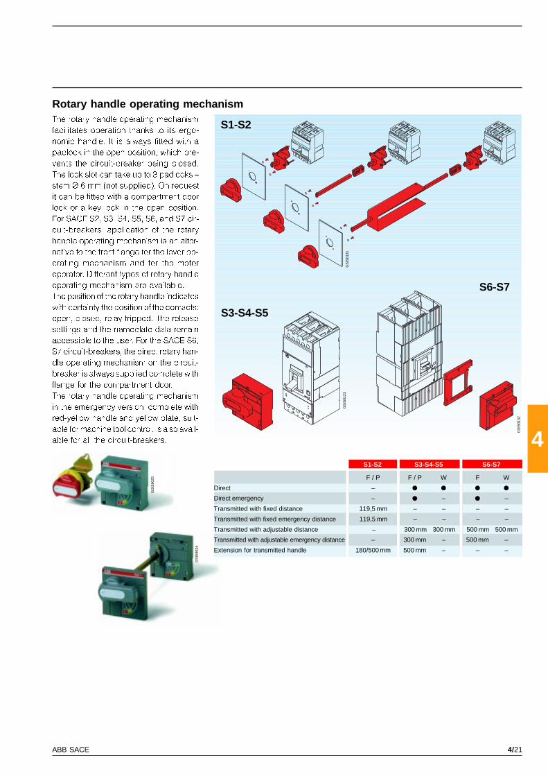
4/21ABB SACE
4
GS
IS90
25
GS
IS90
24
S1-S2 S3-S4-S5 S6-S7
S1-S2
S3-S4-S5
S6-S7
GS
IS01
23G
SIS
0131
GS
IS01
32
Rotary handle operating mechanismThe rotary handle operating mechanism
facilitates operation thanks to its ergo-
nomic handle. It is always fitted with a
padlock in the open position, which pre-
vents the circuit-breaker being closed.
The lock slot can take up to 3 padlocks �
stem Ø 6 mm (not supplied). On request
it can be fitted with a compartment door
lock or a key lock in the open position.
For SACE S2, S3, S4, S5, S6, and S7 cir-
cuit-breakers, application of the rotary
handle operating mechanism is an alter-
native to the front flange for the lever op-
erating mechanism and for the motor
operator. Different types of rotary handle
operating mechanism are available.
The position of the rotary handle indicates
with certainty the position of the contacts:
open, closed, relay tripped. The release
settings and the nameplate data remain
accessible to the user. For the SACE S6,
S7 circuit-breakers, the direct rotary han-
dle operating mechanism on the circuit-
breaker is always supplied complete with
flange for the compartment door.
The rotary handle operating mechanism
in the emergency version, complete with
red-yellow handle and yellow plate, suit-
able for machine tool control, is also avail-
able for all the circuit-breakers.
F / P F / P W F W
Direct –
Direct emergency – – –
Transmitted with fixed distance 119,5 mm – – – –
Transmitted with fixed emergency distance 119,5 mm – – – –
Transmitted with adjustable distance – 300 mm 300 mm 500 mm 500 mm
Transmitted with adjustable emergency distance – 300 mm – 500 mm –
Extension for transmitted handle 180/500 mm 500 mm – – –
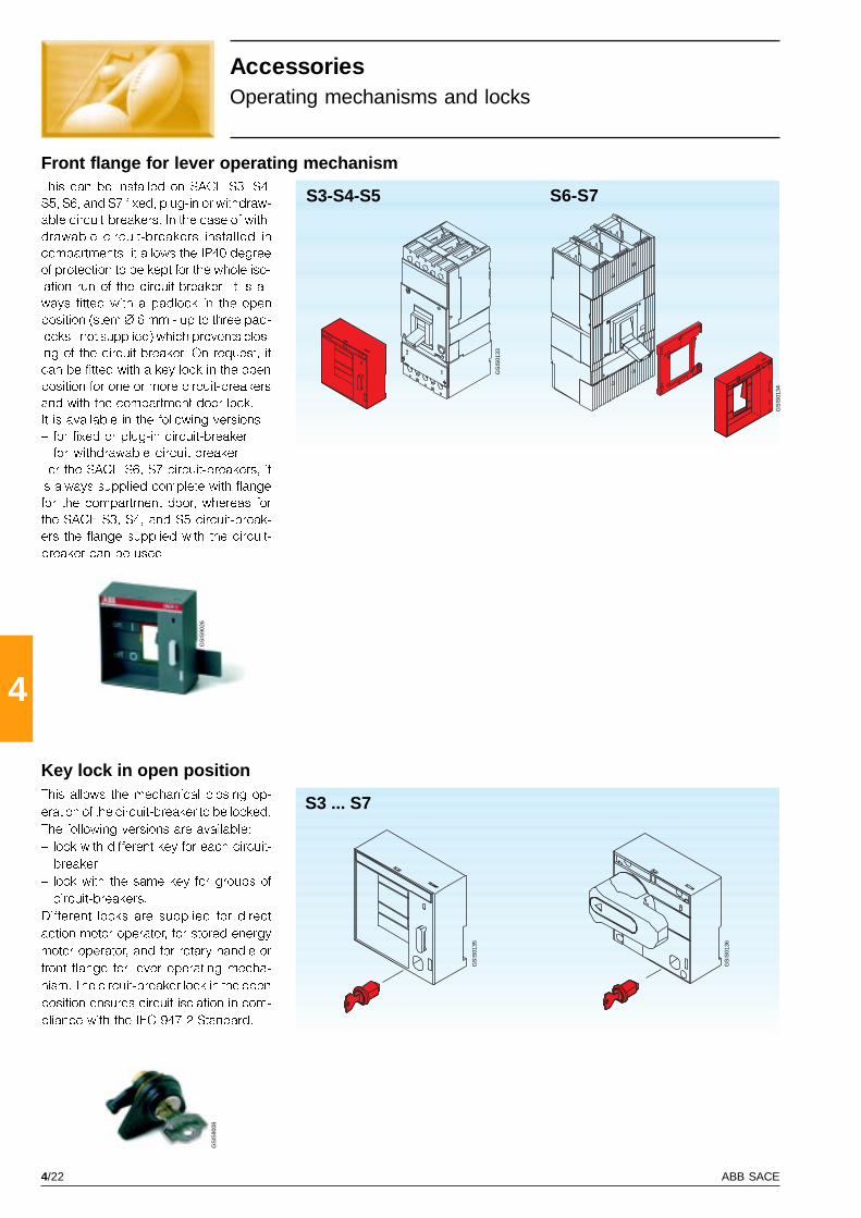
4/22 ABB SACE
4
GS
IS90
08
GS
IS90
26 S3-S4-S5 S6-S7
GS
IS01
33
GS
IS01
34
S3 ... S7
GS
IS01
35
GS
IS01
36
This can be installed on SACE S3, S4,
S5, S6, and S7 fixed, plug-in or withdraw-
able circuit-breakers. In the case of with-
drawable circuit-breakers installed in
compartments, it allows the IP40 degree
of protection to be kept for the whole iso-
lation run of the circuit-breaker. It is al-
ways fitted with a padlock in the open
position (stem Ø 6 mm - up to three pad-
locks - not supplied) which prevents clos-
ing of the circuit-breaker. On request, it
can be fitted with a key lock in the open
position for one or more circuit-breakers
and with the compartment door lock.
It is available in the following versions:
� for fixed or plug-in circuit-breaker.
� for withdrawable circuit-breaker.
For the SACE S6, S7 circuit-breakers, it
is always supplied complete with flange
for the compartment door, whereas for
the SACE S3, S4, and S5 circuit-break-
ers the flange supplied with the circuit-
breaker can be used.
This allows the mechanical closing op-
eration of the circuit-breaker to be locked.
The following versions are available:
� lock with different key for each circuit-
breaker
� lock with the same key for groups of
circuit-breakers.
Different locks are supplied for direct
action motor operator, for stored energy
motor operator, and for rotary handle or
front flange for lever operating mecha-
nism. The circuit-breaker lock in the open
position ensures circuit isolation in com-
pliance with the IEC 947-2 Standard.
AccessoriesOperating mechanisms and locks
Front flange for lever operating mechanism
Key lock in open position
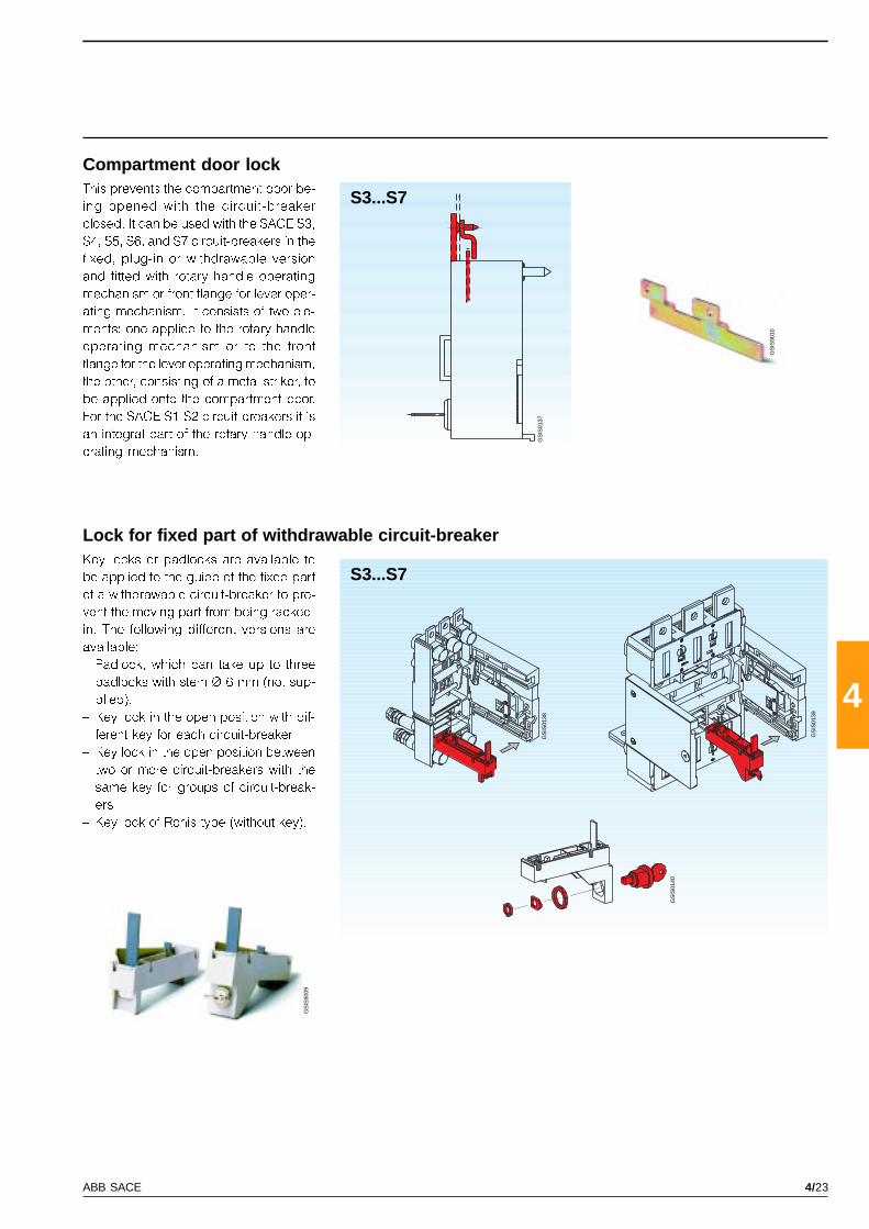
4/23ABB SACE
4
GS
IS90
10
GS
IS90
09
S3...S7
GS
IS01
37
S3...S7
GS
IS01
38
GS
IS01
39
GS
IS01
40
Compartment door lockThis prevents the compartment door be-
ing opened with the circuit-breaker
closed. It can be used with the SACE S3,
S4, S5, S6, and S7 circuit-breakers in the
fixed, plug-in or withdrawable version
and fitted with rotary handle operating
mechanism or front flange for lever oper-
ating mechanism. It consists of two ele-
ments: one applied to the rotary handle
operating mechanism or to the front
flange for the lever operating mechanism,
the other, consisting of a metal striker, to
be applied onto the compartment door.
For the SACE S1-S2 circuit-breakers it is
an integral part of the rotary handle op-
erating mechanism.
Lock for fixed part of withdrawable circuit-breakerKey locks or padlocks are available to
be applied to the guide of the fixed part
of a withdrawable circuit-breaker to pre-
vent the moving part from being racked-
in. The following different versions are
available:
� Padlock, which can take up to three
padlocks with stem Ø 6 mm (not sup-
plied).
� Key lock in the open position with dif-
ferent key for each circuit-breaker
� Key lock in the open position between
two or more circuit-breakers with the
same key for groups of circuit-break-
ers
� Key lock of Ronis type (without key).
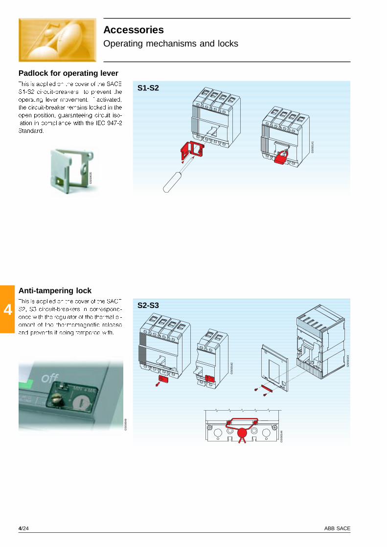
4/24 ABB SACE
4
GS
IS90
35
GS
IS90
49
GS
IS01
43
GS
IS01
42
GS
IS01
44
S2-S3G
SIS
0141
S1-S2
Anti-tampering lockThis is applied on the cover of the SACE
S2, S3 circuit-breakers in correspond-
ence with the regulator of the thermal el-
ement of the thermomagnetic release
and prevents it being tampered with.
This is applied on the cover of the SACE
S1-S2 circuit-breakers to prevent the
operating lever movement. If activated,
the circuit-breaker remains locked in the
open position, guaranteeing circuit iso-
lation in compliance with the IEC 947-2
Standard.
AccessoriesOperating mechanisms and locks
Padlock for operating lever

4/25ABB SACE
4
GS
IS01
46
GS
IS01
45
S3 ... S7
Mechanical interlock between two circuit-breakersThis allows installation of two circuit-
breakers on a single support and, by
means of special lever mechanism,
makes them mechanically inter-depend-
ent. It prevents operation in parallel of two
power supply sources (e.g.: normal -
emergency). It consists of a kit with le-
vers and assembly accessories and a
metallic support.
The circuit-breakers and any operating
mechanism accessories must be ordered
separately. The mechanical interlock is
available for SACE S3, S4, S5, S6, and
S7 circuit-breakers in side by side and
superimposed versions.
To be able to take the circuit-breakers
mounted directly on the interlocking
plate, the code �1SDA050093R1� must
be specified as an accessory of the sec-
ond circuit-breaker (or fixed part) which
is to be interlocked.
N.B. for the S3X, S4X , S6X circuit-breakers,
only the version side by side can be used.

4/26 ABB SACE
4 GS
IS90
27
S1
GS
IS01
47
All the circuit-breakers in the SACE Isomax S series are preset for combined assembly with residual current releases. In partic ular,
the SACE S1, S2, and S3 circuit-breakers can be combined with residual current releases in the SACE RC210, RC211 or RC212
series, in the version side by side or underneath the circuit-breaker.
Apart from the protection against overloads and short-circuits typical of circuit-breakers, the residual current circuit-breake rs
which are derived from them also guarantee protection against earth fault currents, thereby ensuring protection against the ris k
of fire. The residual current releases can also be mounted on the SACE S2D and S3D switch-disconnectors. In that case, the
derived apparatus is a �pure� residual-current circuit-breaker, which therefore guarantees only residual current protection an d
not the protections typical of circuit-breakers. The �pure� residual-current circuit-breakers are only sensitive to the earth f ault
current and are generally applied as main isolators in small distribution switchboards towards end users.
The use of �pure� and �non-pure� residual-current circuit-breakers allows continuous monitoring of the state of insulation of t he
installation, ensuring effective protection against the risk of fire and explosion and, in the case of devices with I Dn £ 30mA, they
guarantee protection of people against indirect and direct contacts to integrate the compulsory measures foreseen by the
standards and by the accident prevention regulations.
The residual-current releases are constructed in compliance with the following standards:
� IEC 947-2 appendix B
� IEC 255-3 and IEC 1000: for protection against unwarranted trips.
AccessoriesResidual current releases
The SACE RC210/1 polarised residual-
current release is available for four-pole
SACE Isomax S1 circuit-breakers for as-
sembly side by side on DIN 50022 rail.
The release is constructed using polar-
ised type technology and acts directly
on the release operating mechanism of
the circuit-breaker, by means of a small
piston which passes through a pre-cut
window on the side of the circuit-breaker.
It is fitted with a test button for periodi-
cally checking the circuit-breaker.
SACE RC210 polarised residual-current release
The SACE RC211 and RC212 residual
current releases can be installed both
on the SACE S1, S2 and S3 circuit-break-
ers and on the SACE S2D and S3D
switch-disconnectors, in the fixed four-
pole version, and can be supplied in two
versions as follows:
� for assembly in position beside the
circuit-breaker
� for assembly in position under the cir-
cuit-breaker.
The following releases are available:
� SACE RC211/1, RC212/1 for S1 circuit-
breakers
SACE RC211, RC212 electronic residual current releases
� SACE RC211/2, RC212/2 for S2 circuit-
breakers
� SACE RC211/3, RC212/3 for S3 circuit-
breakers.
They are constructed using analogue
technology and act directly on the cir-
cuit-breaker by means of an opening
solenoid, supplied with the release, to
be housed in the special slot made in
the area of the third pole.
They do not require an auxiliary power
supply since they are supplied directly
from the network and their operation is
guaranteed even with only a single
phase supplied with voltage and in the
presence of one-direction pulsating cur-
rents with continuous components.
The operating conditions of the appara-
tus can be controlled constantly by
means of the test pushbutton of the elec-
tronic circuit and the residual current trip
magnetic indicator.
The circuit-breaker complete with re-
sidual current release can be fitted with
the electrical accessories normally avail-
able for the circuit-breaker. The opening
and undervoltage releases are housed
in the special slot made in the fourth pole.

4/27ABB SACE
4
S1-S2-S3
S1-S2-S3
GS
IS01
49
GS
IS01
48
nals for cables can be mounted or the
rear terminals using the kit with 4 pieces
for the circuit-breaker can be mounted
(code 1SDA023365R1) and the kit for
residual current release (code
1SDA025543R1).
This is supplied complete with:
� an opening solenoid to be housed in
the area of the third pole, complete with
plug-socket connector for connection
to the residual current release
� plug connector to make the connec-
tion of the remote opening pushbutton
(to be provided by the customer) with
the SACE RC212 residual current re-
lease
� flange for compartment door (one for
SACE S1, S2; two for SACE S3)
� protection for assembly in the area
between the circuit-breaker and re-
sidual current release.
For SACE S1, S2 circuit-breakers, the re-
sidual current release is supplied with
front terminals for cables On request, the
rear threaded terminals can be mounted,
using standard kit of the circuit-breaker.
For SACE S3 circuit-breakers, the re-
sidual current release is supplied with
front terminals (together with a front flange
H= 45mm for circuit-breaker). On re-
quest, using the standard kit of the cir-
cuit-breaker, front terminals for cables,
extended front terminals, or rear termi-
Residual current release under the four-pole version circuit-breaker
Residual current release beside the four-pole version circuit-breaker
This is supplied complete with:
� power cables for connection to the
lower terminals of the circuit-breaker
(respecting correspondence with the
neutral and phases)
� an opening solenoid to be housed in
the area of the third pole, complete with
plug-socket connector for connection
to the residual current release
� 2 brackets for fixing on DIN rail (one
for the circuit-breaker and one for the
residual current release)
� plug connector to make the connec-
tion of the remote opening pushbutton
(to be provided by the customer).
For SACE S1-S2 circuit-breakers the re-
sidual current release is fitted with front
terminals for cables.
For the SACE S3 circuit-breaker, the re-
sidual current release is fitted with front
terminals and is also supplied with a front
flange H= 45 mm for the circuit-breaker.
beside
under
On request, the front terminals for ca-
bles can be mounted, using the stand-
ard circuit-breaker kit.

4/28 ABB SACE
4
SACE RC210 SACE RC211 SACE RC212
GS
IS00
77
Technical characteristicsResidual current releases
Technology polarised type electronic electronic
Action direct with solenoid with solenoid
Primary operating voltage [V] up to 500 220 ... 500 50 ... 500
Operation frequency [Hz] 50 ÷ 60 Hz ± 10% 50 ÷ 60 Hz ± 10% 50 ÷ 60 Hz ± 10%
Range of test operation [V] 230 ... 500 220 ... 500 50 ... 500
Rated service current [A] up to 125 up to 250 up to 250
Trip thresholds IDn [A] 0,3 - 0,5 0,03 - 0,1 - 0,3 0,03 - 0,1 - 0,3 - 0,5 - 3
Tolerance for IDn [%] +0, -25 +0, -20
Trip times [s] instantaneous instantaneous 0 - 0,1 - 0,25 - 0,5 - 1 - 1,5
Tolerance over trip times [%] ± 20
Trip signalling
Self-supply
Input for remote opening
Indication of pre-alarm at 50%
AC type only for alternating current
Type A for alternating current, pushbutton
Low sensitivity
High sensitivity
Mounting under the circuit-breaker
Mounting beside the circuit-breaker
Dimensions (L x H x P) [mm] 103 x 120 x 70 120 x 120 x 70 140 x 170 x 108
AccessoriesResidual current releases
Connection to the residual current circuit-breaker network
Network connection diagrams for which the protection
is active even with only one phase supplied with voltage
Network connection diagrams for which the protection
is active with at least two phases supplied with voltage
(1) Terminal to be connected to the neutral or to the earthing conductor.

4/29ABB SACE
4
GS
IS90
46
SACE RCQ
SACE RCQ switchboard residual-current relaysThe SACE Isomax S4, S5, S6, and S7 cir-
cuit-breakers can be combined with the
SACE RCQ switchboard residual-current
relay with separate toroid (to be installed
externally on the line conductors) and
satisfies requirements with trip thresholds
up to 30 A and times up to 5 s or where
the installation conditions are particu-
larly restrictive, such as circuit-breakers
already installed, limited space in the cir-
cuit-breaker compartment.
Thanks to its wide setting range, the
SACE RCQ switchboard residual-current
relay is suitable for applications where a
coordinated residual current protection
system is to be constructed at the vari-
ous distribution levels, from the main
switchboard to the end user. It is particu-
larly suitable where low sensitivity re-
sidual current protection is required, for
example in partial (current-type) or total
(time-type) selective chains, and for high
sensitivity applications (with physiologi-
cal sensitivity) to realise protection of
people against direct contacts
On a drop in the auxiliary power supply
voltage, the opening command inter-
venes after a minimum time of 100 ms
and after the time set plus 100 ms.
The SACE RCQ relay is suitable for use
in the presence of earth currents of alter-
nating type only (AC Type), for alternat-
ing current and/or pushbutton with con-
tinuous components (Type A) and is suit-
able for carrying out residual current se-
lectivity .
The SACE RCQ relay is of the type with
indirect action and acts on the release
mechanism of the circuit-breaker by
means of the circuit-breaker shunt open-
ing release (to be ordered by the user)
to be housed in the special slot made on
the third pole of the circuit-breaker.
Residual-current relay
Power supply voltage AC [V] 80 ... 500
DC [V] 48 ... 125
Operation frequency [Hz] 50 ÷ 60 Hz ± 10%
Trip threshold adjustment IDn
- 1a range of adjustments [A] 0,03 - 0,05 - 0,1 - 0,3 - 0,5
- 2a range of adjustments [A] 1 - 3 - 5 - 10 - 30
Trip time adjustment [s] 0 - 0,1 - 0,2 - 0,3 - 0,5 - 0,7 - 1 - 2 - 3 - 5
Pre-alarm threshold adjustment [%] x IDn 25 ... 75% x IDn
Range of use of the closed transformers IDn
- Toroidal transformer Ø 60 [mm] [A] 0,03 ... 30
- Toroidal transformer Ø 110 [mm] [A] 0,03 ... 30
- Toroidal transformer Ø 185 [mm] [A] 0,1 ... 30
Range of use of the transformers which can be opened IDn
- Toroidal transformer Ø 110 [mm] [A] 0,3 ... 30
- Toroidal transformer Ø 180 [mm] [A] 0,3 ... 30
- Toroidal transformer Ø 230 [mm] [A] 1 ... 30
Alarm pre-threshold signalling Yellow flashing LED
1 N.O. changeover contact
6 A - 250 V AC 50/60 Hz
Residual-current relay trip signalling Yellow flashing LED
2 changeover contacts (N.O. N.C.; N.O.)
6 A - 250 VAC 50/60 Hz
Remote opening command N.O. Contact
Trip time 15 ms
Connection to the toroidal transformer By means of 4 twisted conductors
Maximum length 5 m
Dimensions L x H x D [mm] 96 x 96 x 131,5
Drilling for assembly on door [mm] 92 x 92
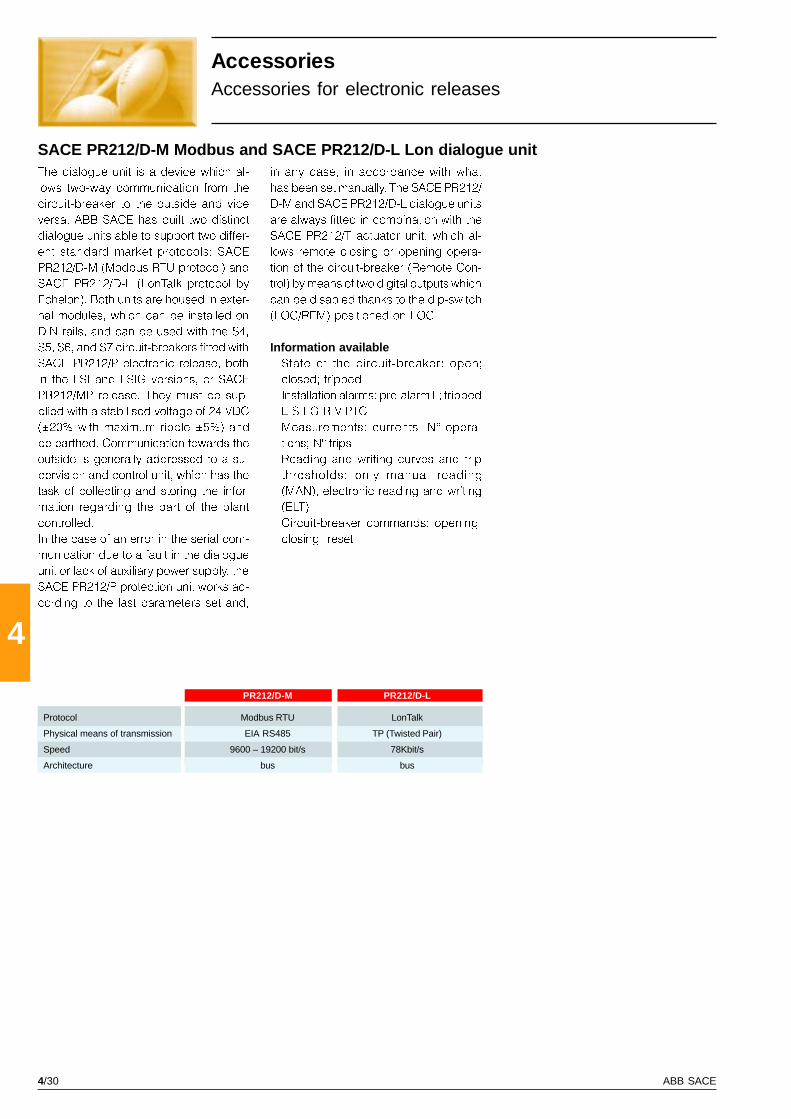
4/30 ABB SACE
4
PR212/DM PR212/D-M PR212/D-L
AccessoriesAccessories for electronic releases
The dialogue unit is a device which al-
lows two-way communication from the
circuit-breaker to the outside and vice
versa. ABB SACE has built two distinct
dialogue units able to support two differ-
ent standard market protocols: SACE
PR212/D-M (Modbus RTU protocol) and
SACE PR212/D-L (LonTalk protocol by
Echelon). Both units are housed in exter-
nal modules, which can be installed on
DIN rails, and can be used with the S4,
S5, S6, and S7 circuit-breakers fitted with
SACE PR212/P electronic release, both
in the LSI and LSIG versions, or SACE
PR212/MP release. They must be sup-
plied with a stabilised voltage of 24 VDC
(±20% with maximum ripple ±5%) and
be earthed. Communication towards the
outside is generally addressed to a su-
pervision and control unit, which has the
task of collecting and storing the infor-
mation regarding the part of the plant
controlled.
In the case of an error in the serial com-
munication due to a fault in the dialogue
unit or lack of auxiliary power supply, the
SACE PR212/P protection unit works ac-
cording to the last parameters set and,
SACE PR212/D-M Modbus and SACE PR212/D-L Lon dialogue unitin any case, in accordance with what
has been set manually. The SACE PR212/
D-M and SACE PR212/D-L dialogue units
are always fitted in combination with the
SACE PR212/T actuator unit, which al-
lows remote closing or opening opera-
tion of the circuit-breaker (Remote Con-
trol) by means of two digital outputs which
can be disabled thanks to the dip-switch
(LOC/REM) positioned on LOC.
Information available� State of the circuit-breaker: open;
closed; tripped
� Installation alarms: pre-alarm L; tripped
L-S-I-G-R-V-PTC
� Measurements: currents; N° opera-
tions; N° trips
� Reading and writing curves and trip
thresholds: only manual reading
(MAN), electronic reading and writing
(ELT)
� Circuit-breaker commands: opening;
closing; reset.
Protocol Modbus RTU LonTalk
Physical means of transmission EIA RS485 TP (Twisted Pair)
Speed 9600 – 19200 bit/s 78Kbit/s
Architecture bus bus
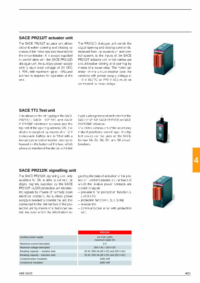
4/31ABB SACE
4
PR212/K
GS
IS90
43
GS
IS90
31
GS
IS90
41
The SACE PR212/T actuator unit allows
circuit-breaker opening and closing by
means of the motor operator mounted on
the circuit-breaker. It is always supplied
in combination with the SACE PR212/D
dialogue unit. An auxiliary power supply
with a stabilised voltage of 24 VDC
(±20%, with maximum ripple - ±5%) and
earthed is required for operation of the
unit.
This allows control of tripping of the SACE
PR211/P, SACE PR212/P, and SACE
PR212/MP electronic releases and the
trip test of the opening solenoid OS. The
device is supplied by means of a 12 V
replaceable battery and is fitted with a
two-pole polarised connector-tracer point
housed on the bottom of the box, which
allows connection of the device to the test
The PR212/D dialogue unit sends the
digital opening and closing commands,
received from the supervision and con-
trol system, to the inputs of the SACE
PR212/T actuator unit, which carries out
circuit-breaker closing and opening by
means of a power relay. The motor op-
erator of the circuit-breaker (use the
versions with power supply voltage at
110 V AC/DC or 220 V AC) must be
connected to these relays.
input bushings located on the front of the
SACE PR211/P, SACE PR212/P, or SACE
PR212/MP releases.
The limited dimensions of the accessory
make it practically pocket-type. The trip
test device can be used on the SACE
Isomax S4, S5, S6, S7, and S8 circuit-
breakers.
SACE PR212/T actuator unit
SACE TT1 Test unit
SACE PR212/K signalling unitThe SACE PR212/K signalling unit, only
available for S8, is able to convert the
digital signals supplied by the SACE
PR212/P - (LSIG) protection unit into elec-
tric signals by means of normally open
electrical contacts. An auxiliary power
supply is needed to operate the unit. It is
connected to the internal bus of the pro-
tection unit by means of a dedicated se-
rial line over which the information re-
garding the state of activation of the pro-
tection functions passes, on the basis of
which the relative power contacts are
closed to signal:
� pre-alarm for protection function L
(I>0.9 x I1)
� protection function L, S, I, G trip
� release trip
� communication error with protection
unit.
Auxiliary power supply 24 V DC ±20%maximum ripple 5%
Maximum current interrupted 5 A
Maximum voltage interrupted 250 V AC / 130 V DC
Breaking capacity – resistive load 50 W / 800 VA (48 V DC and 220 V AC)
Breaking capacity - inductive load 25 W / 500 VA (48 V DC and 220 V AC)
Contact/contact insulation 1000 Veff
Contact/coil insulation 2000 Veff

4/32 ABB SACE
4
PR212/P (LSI-LSIG)
PR212/MP (LRIU)
GS
IS91
47
PR010/K
The SACE PR010/K signalling unit can
convert the signals received via the bus
from the SACE PR212/P (LSI or LSIG) and
SACE PR212/MP (LRIU) protection units
into electric signals by means of normally
open electrical power contacts.
An auxiliary power supply with a voltage
stabilised at 24V DC (±20% with maxi-
mum ripple - ±5%) and earthed is
needed to operate the unit.
It is connected to the Internal Bus of the
protection unit by means of a dedicated
serial line over which the information re-
garding the state of activation of the pro-
tection functions passes, on the basis of
which the relative power contacts are
closed.
In particular, the following signals are
available:
AccessoriesAccessories for electronic releases
K51
1 Protection L alarm
2 Protection S alarm
3 Protection I alarm
4 Protection G alarm
5 Bus K.O.
7 Release trip
8 Protection L pre-alarm
Auxiliary power supply 24 V DC ±20%maximum ripple 5%
Maximum current interrupted 5 A
Maximum voltage interrupted 250 V AC / 130 V DC
Breaking capacity – resistive load 50 W / 800 VA (48 V DC and 220 V AC)
Breaking capacity – inductive load 25 W / 500 VA (48 V DC and 220 V AC)
Contact/contact insulation 1000 Veff
Contact/coil insulation 2000 Veff
K51
1 Protection L alarm
2 Protection R alarm
3 Protection I alarm
4 Protection U alarmWelded contactor alarm contacts
5 Bus K.O.
6 PTC alarm(temperature sensor on motor) (*)
Generic input 0/1
7 Release trip
8 Protection L pre-alarmBack-up protection alarm
(*) alternatively by means of dip-switch
SACE PR010/K signalling unitAlarm signalling remains active for the
whole duration of the overload up to any
release trip.
The protection trip signals remain ac-
tive during the timing phase and remain
that way even after release trip.
A Reset pushbutton on the front of the
unit allows the state of all signals to be
reset.
There are also two LEDs available on the
unit for visually signalling the following
information:
� �Power ON�: auxiliary power supply
present
� �TX (Int Bus)�: flashing synchronised
with the communication activity with
the Internal Bus
The table below shows the characteris-
tics of the signalling relays available in
the SACE PR010/K unit.
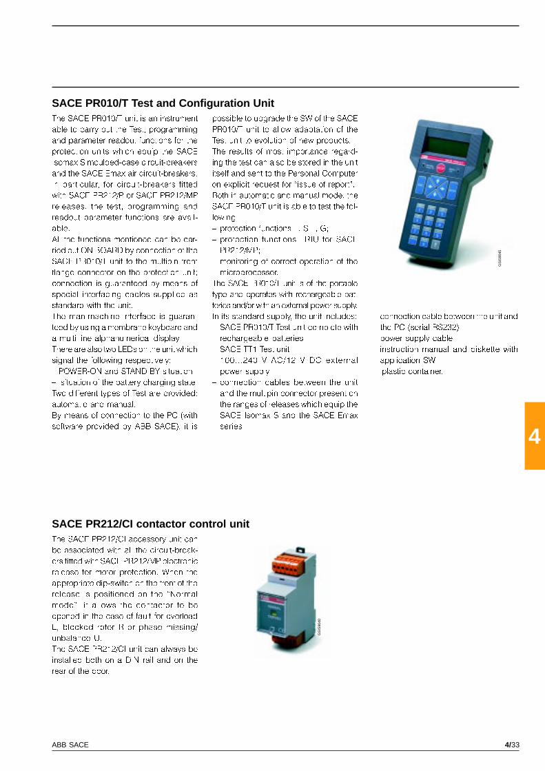
4/33ABB SACE
4
GS
IS90
45
GS
IS90
40
SACE PR010/T Test and Configuration UnitThe SACE PR010/T unit is an instrument
able to carry out the Test, programming
and parameter readout functions for the
protection units which equip the SACE
Isomax S moulded-case circuit-breakers
and the SACE Emax air circuit-breakers.
In particular, for circuit-breakers fitted
with SACE PR212/P or SACE PR212/MP
releases, the test, programming and
readout parameter functions are avail-
able.
All the functions mentioned can be car-
ried out ON BOARD by connection of the
SACE PR010/T unit to the multipin front
flange connector on the protection unit;
connection is guaranteed by means of
special interfacing cables supplied as
standard with the unit.
The man-machine interface is guaran-
teed by using a membrane keyboard and
a multi-line alphanumerical display.
There are also two LEDs on the unit which
signal the following respectively:
� POWER-ON and STAND BY situation
� situation of the battery charging state.
Two different types of Test are provided:
automatic and manual.
By means of connection to the PC (with
software provided by ABB SACE), it is
possible to upgrade the SW of the SACE
PR010/T unit to allow adaptation of the
Test unit to evolution of new products.
The results of most importance regard-
ing the test can also be stored in the unit
itself and sent to the Personal Computer
on explicit request for �issue of report�.
Both in automatic and manual mode, the
SACE PR010/T unit is able to test the fol-
lowing:
� protection functions L, S, I, G;
� protection functions LRIU for SACE
PR212/MP;
� monitoring of correct operation of the
microprocessor.
The SACE PR010/T unit is of the portable
type and operates with rechargeable bat-
teries and/or with an external power supply.
In its standard supply, the unit includes:
� SACE PR010/T Test unit complete with
rechargeable batteries
� SACE TT1 Test unit
� 100...240 V AC/12 V DC external
power supply
� connection cables between the unit
and the multipin connector present on
the ranges of releases which equip the
SACE Isomax S and the SACE Emax
series
� connection cable between the unit and
the PC (serial RS232)
� power supply cable
� instruction manual and diskette with
application SW
� plastic container.
SACE PR212/CI contactor control unitThe SACE PR212/CI accessory unit can
be associated with all the circuit-break-
ers fitted with SACE PR212/MP electronic
release for motor protection. When the
appropriate dip-switch on the front of the
release is positioned on the �Normal
mode�, it allows the contactor to be
opened in the case of fault for overload
L, blocked rotor R or phase missing/
unbalance U.
The SACE PR212/CI unit can always be
installed both on a DIN rail and on the
rear of the door.
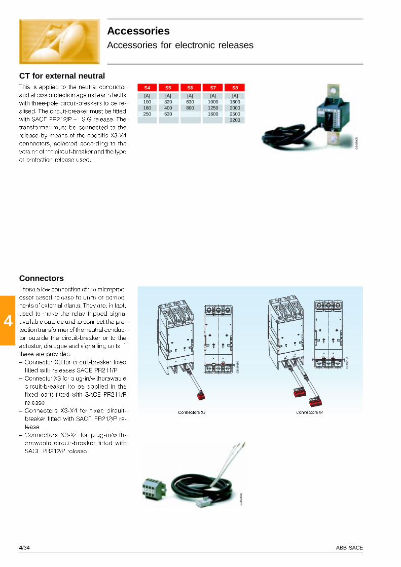
4/34 ABB SACE
4
GS
IS90
05
GS
IS90
30
GS
IS01
51
GS
IS01
50
S4 S5 S6 S7 S8
[A] [A] [A] [A] [A]100 320 630 1000 1600160 400 800 1250 2000250 630 1600 2500
3200
Connectors X3
ConnectorsThese allow connection of the microproc-
essor-based release to units or compo-
nents of external plants. They are, in fact,
used to make the relay tripped signal
available outside and to connect the pro-
tection transformer of the neutral conduc-
tor outside the circuit-breaker or to the
actuator, dialogue and signalling units, if
these are provided.
� Connector X3 for circuit-breaker fixed
fitted with releases SACE PR211/P
� Connector X3 for plug-in/withdrawable
circuit-breaker (to be applied in the
fixed part) fitted with SACE PR211/P
release
� Connectors X3-X4 for fixed circuit-
breaker fitted with SACE PR212/P re-
lease
� Connectors X3-X4 for plug-in/with-
drawable circuit-breaker fitted with
SACE PR212/P release
CT for external neutralThis is applied to the neutral conductor
and allows protection against earth faults
with three-pole circuit-breakers to be re-
alised. The circuit-breaker must be fitted
with SACE PR212/P � LSIG release. The
transformer must be connected to the
release by means of the specific X3-X4
connectors, selected according to the
version of the circuit-breaker and the type
of protection release used.
Connectors X4
AccessoriesAccessories for electronic releases
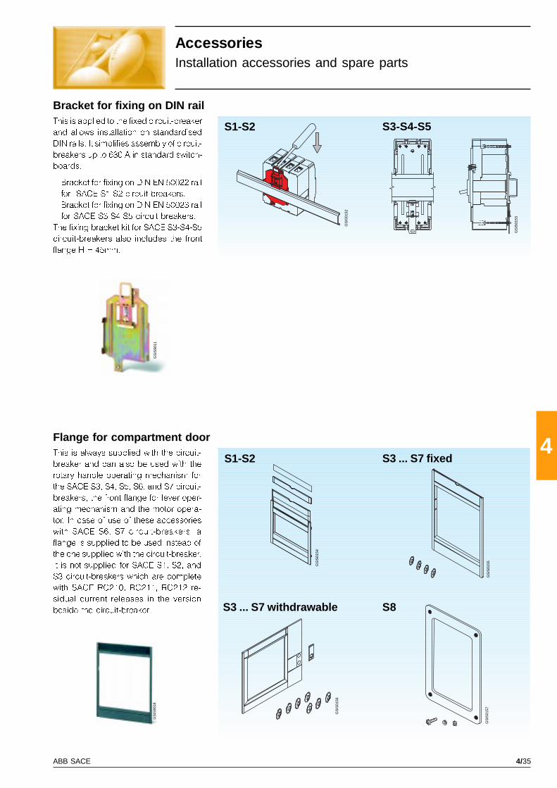
4/35ABB SACE
4
GS
IS90
11G
SIS
9018
S1-S2 S3-S4-S5
GS
IS01
56
GS
IS01
54
S8
GS
IS01
57G
SIS
0155
S1-S2
GS
IS01
53
GS
IS01
52
Bracket for fixing on DIN rail
Flange for compartment doorThis is always supplied with the circuit-
breaker and can also be used with the
rotary handle operating mechanism for
the SACE S3, S4, S5, S6, and S7 circuit-
breakers, the front flange for lever oper-
ating mechanism and the motor opera-
tor. In case of use of these accessories
with SACE S6, S7 circuit-breakers, a
flange is supplied to be used instead of
the one supplied with the circuit-breaker.
It is not supplied for SACE S1, S2, and
S3 circuit-breakers which are complete
with SACE RC210, RC211, RC212 re-
sidual current releases in the version
beside the circuit-breaker.
S3 ... S7 fixed
S3 ... S7 withdrawable
AccessoriesInstallation accessories and spare parts
This is applied to the fixed circuit-breaker
and allows installation on standardised
DIN rails. It simplifies assembly of circuit-
breakers up to 630 A in standard switch-
boards.
� Bracket for fixing on DIN EN 50022 rail
for SACE S1-S2 circuit-breakers.
� Bracket for fixing on DIN EN 50023 rail
for SACE S3-S4-S5 circuit-breakers.
The fixing bracket kit for SACE S3-S4-S5
circuit-breakers also includes the front
flange H = 45mm.

4/36 ABB SACE
4
S1-S2
GS
IS90
34
GS
IS01
58
AccessoriesInstallation accessories and spare parts
Spare partsThe following spare parts are available:
� operating lever
� cover group
� arcing chambers
� isolating contacts
� opening solenoid for the SACE
RC211and RC212 residual current re-
leases
� kit with washers, screws and dowels
for assembly of the connection termi-
nals.
For further details, please ask the Serv-
ice Division of ABB SACE for the spare
parts catalogue.
IP54 protection for rotary handleThis allows IP54 degree of protection to
be attained. It is available in the follow-
ing versions:
� for rotary handle operating mechanism
on compartment door with fixed dis-
tance for SACE S1-S2 circuit-breakers
� for rotary handle operating mechanism
on compartment door with adjustable
distance for circuit-breakers SACE S3-
S4-S5-S6 and S7 circuit-breakers.

5/1ABB SACE
5
Index
Characteristic curves
Trip curves for distribution
Circuit-breakers with thermomagnetic releases ................................................................ 5/2
Circuit-breakers with SACE PR211/P, SACE PR212/P electronic releases ..................... 5/7
Trip curves for motor protection
Circuit-breakers with magnetic only releases ................................................................... 5/9
Use of the trip curves of circuit-breakers with SACE PR212/MP electronic release ...... 5/10
Circuit-breakers with electronic release SACE PR212/MP ............................................... 5/12
Limitation curves
230 V .................................................................................................................................... 5/14
400-440 V ............................................................................................................................ 5/17
500 V .................................................................................................................................... 5/20
690 V .................................................................................................................................... 5/21
Specific let-through energy curves
230 V .................................................................................................................................... 5/24
400-440 V ............................................................................................................................ 5/27
500 V .................................................................................................................................... 5/30
690 V .................................................................................................................................... 5/31
Technical information
Temperature performance
Circuit-breakers with electronic releases .......................................................................... 5/34
Circuit-breakers with thermomagnetic releases ................................................................ 5/39
Power loss values ............................................................................................................. 5/40
Operation and protection of the low-voltage side of three-phase transformers .. 5/42
Operation and protection of three-phase AC capacitors .......................................... 5/44
Protection of three-phase AC generators .................................................................... 5/46
Applications in direct current ......................................................................................... 5/47
Backup protection (backup table) ................................................................................. 5/50
Characteristic curves andtechnical information
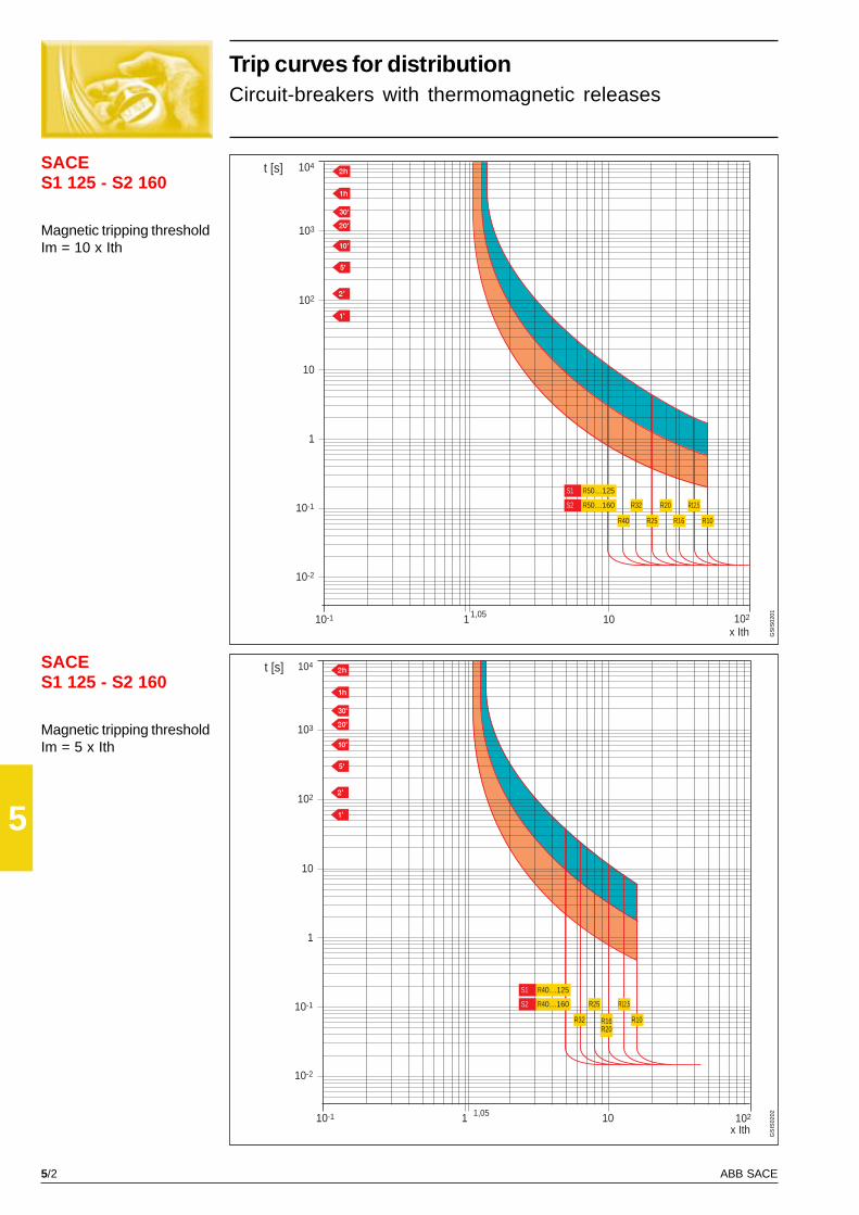
5/2 ABB SACE
5
SACES1 125 - S2 160
SACES1 125 - S2 160
103
t [s]
10-1
x Ith101
10
1
102
10-1
10-2
1,05 102
104
R32
R40 R25
R20
R16
R12,5
R10
S1 R50…125
S2 R50…160
103
t [s]
10-1
x Ith101
10
1
102
10-1
10-2
1,05 102
104
R25
R32 R16R20
R10
R12,5
R40…125S1
R40…160S2
GS
IS02
01G
SIS
0202
Trip curves for distributionCircuit-breakers with thermomagnetic releases
Magnetic tripping thresholdIm = 10 x Ith
Magnetic tripping thresholdIm = 5 x Ith
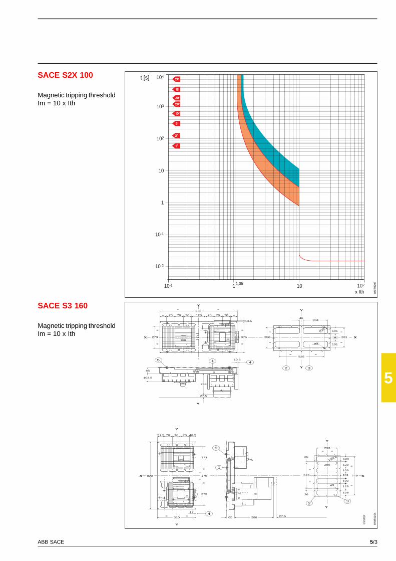
5/3ABB SACE
5
SACE S2X 100
SACE S3 160 Y
X
650
5
Y
X
Y
X X
Y
Y
Y
Y
Y
1 4
2 3
70 70 70 120 70 70 70 ==
375
13.5
=
=
10.5
288
27.5
350
=
=
273
=
=
525= =
ø9
R30
331
=
=
101
28446
70 70 7051.5 48.5
273
273
175
1
417
310 ==
=
=820
28865 27.5
5
23
293= =
525
=
=ø9
779
109
=
=
==
65
103.5
280
GSIS
0024
101
A
26
26
109
129
101
109
109
129
R20
103
t [s]
10-1
x Ith101
10
1
102
10-1
10-2
1,05 102
104
GS
IS02
03G
SIS
0204
Magnetic tripping thresholdIm = 10 x Ith
Magnetic tripping thresholdIm = 10 x Ith

5/4 ABB SACE
5
SACES3 160 - S3 250
SACE S3 160
103
t [s]
10-1
x Ith101
10
1
102
10-1
10-2
1,05 102
104
R80…R160S3 160
R200, R250S3 250
103
t [s]
10-1
x Ith101
10
1
102
10-1
10-2
1,05 102
104
R32R50
GS
IS02
05G
SIS
0206
Trip curves for distributionCircuit-breakers with thermomagnetic releases
Magnetic tripping thresholdIm = 10 x Ith
Magnetic tripping thresholdIm = 5 x Ith

5/5ABB SACE
5
SACES3 160 - S3 250
SACE S5 400(R320-400)
SACE S5 630(R500)
103
t [s]
10-1
x Ith101
10
1
102
10-1
10-2
1,05 102
104
R80…R160S3 160
R200, R250S3 250
103
t [s]
10-1
x Ith101
10
1
102
10-1
10-2
1,05 102
104
GS
IS02
07G
SIS
0208
Magnetic tripping thresholdIm = 3 x Ith
Magnetic tripping thresholdIm = 5 x Ith
Thermal tripping thresholdIn = 0,7÷1 x Ith
Magnetic tripping thresholdIm = 5÷10 x Ith
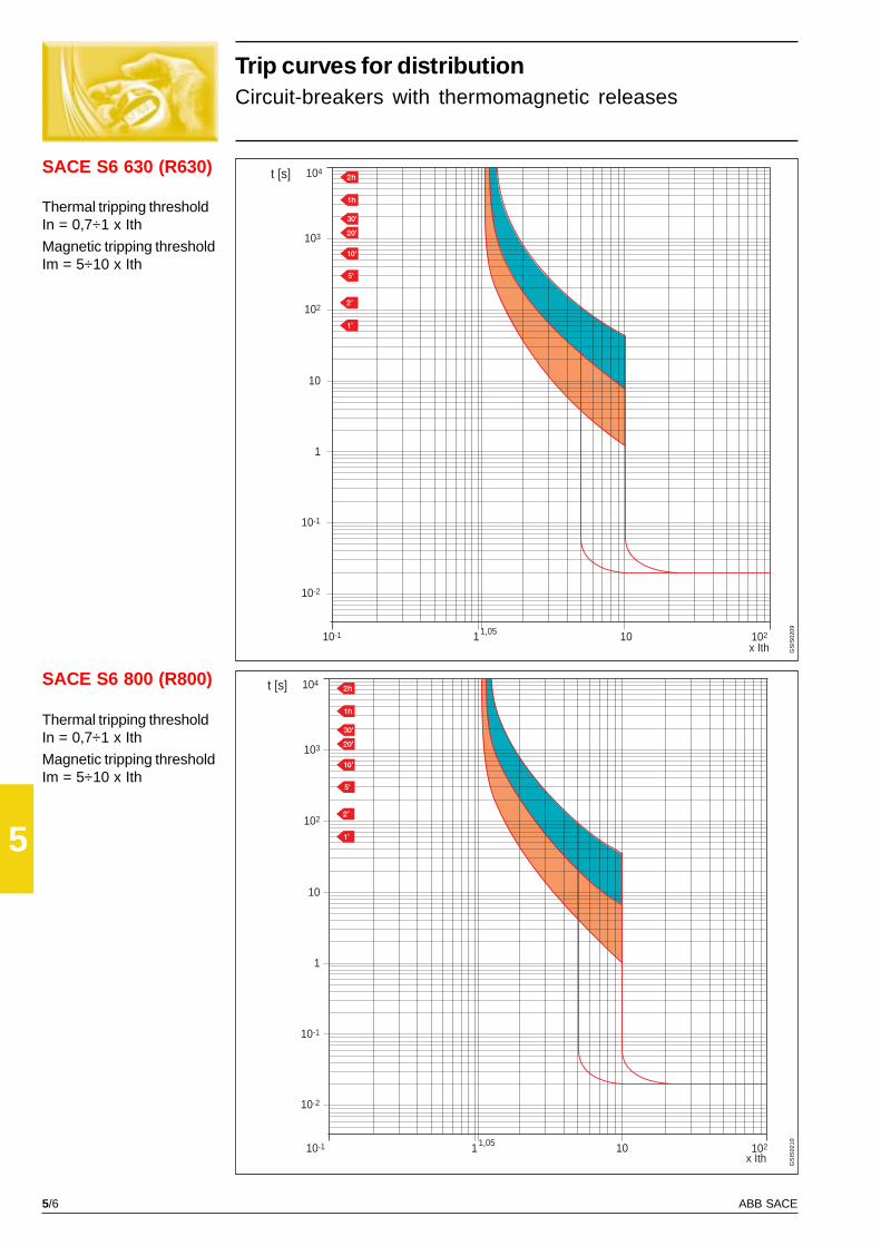
5/6 ABB SACE
5
SACE S6 630 (R630)
SACE S6 800 (R800)
103
t [s]
10-1
x Ith101
10
1
102
10-1
10-2
1,05 102
104
103
t [s]
x Ith10-1 101
10
1
102
10-1
10-2
1,05 102
104
GS
IS02
09G
SIS
0210
Trip curves for distributionCircuit-breakers with thermomagnetic releases
Thermal tripping thresholdIn = 0,7÷1 x Ith
Magnetic tripping thresholdIm = 5÷10 x Ith
Thermal tripping thresholdIn = 0,7÷1 x Ith
Magnetic tripping thresholdIm = 5÷10 x Ith
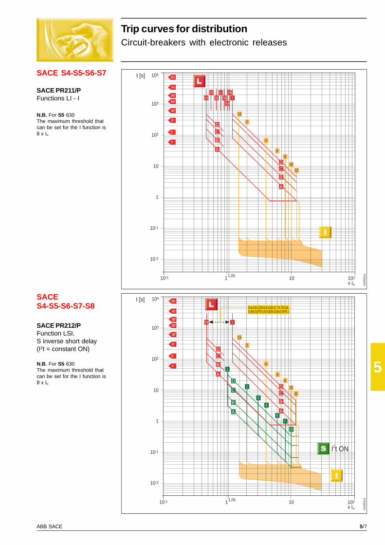
5/7ABB SACE
5
SACE S4-S5-S6-S7
SACES4-S5-S6-S7-S8
103
t [s]
10-1
x In101
10
1
102
10-1
10-2
1,05 102
104
DC
B
A
A
B
CD
0,40,5
0,60,7
0,80,9
0,951
4
2
1,5
68
12
10
103
t [s]
10-1
x In101
10
1
102
10-1
10-2
1,05 102
104
I2t ON
0,4-0,5-0,55-0,6-0,65-0,7-0,75-0,8-0,85-0,875-0,9-0,925-0,95-0,975-1
0,4 1
1,5
2
4
6
12
10
8
A
B
CD
DC
B
A
1
D
C
B
A
2
3
4
68
10
GS
IS02
11G
SIS
0212
Trip curves for distributionCircuit-breakers with electronic releases
SACE PR211/PFunctions LI - I
N.B. For S5 630The maximum threshold thatcan be set for the I function is8 x In
SACE PR212/PFunction LSI,S inverse short delay(I2t = constant ON)
N.B. For S5 630The maximum threshold thatcan be set for the I function is8 x In
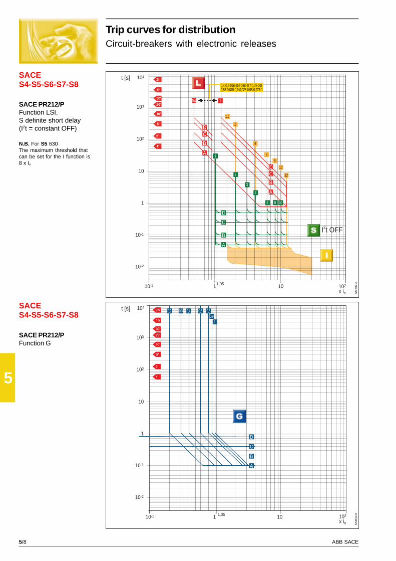
5/8 ABB SACE
5
SACES4-S5-S6-S7-S8
SACES4-S5-S6-S7-S8
103
t [s]
10-1
x In101
10
1
102
10-1
10-2
1,05 102
104
0,4
6 8 10
1
0,4-0,5-0,55-0,6-0,65-0,7-0,75-0,8-0,85-0,875-0,9-0,925-0,95-0,975-1
I2t OFF
4
3
2
D
C
B
A
DC
B
A
1
A
B
CD
1,5
2
4
6
8
10
12
103
t [s]
10-1
x In101
10
1
102
10-1
10-2
1,05 102
1040,30,2 0,4 0,6 0,8
0,91
B
C
D
A
GS
IS02
13G
SIS
0214
Trip curves for distributionCircuit-breakers with electronic releases
SACE PR212/PFunction LSI,S definite short delay(I2t = constant OFF)
N.B. For S5 630The maximum threshold thatcan be set for the I function is8 x In
SACE PR212/PFunction G
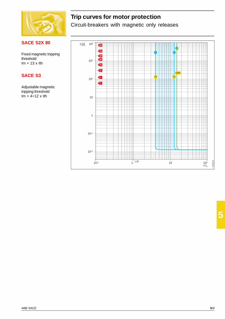
5/9ABB SACE
5
SACE S2X 80
103
t [s]
10-1
x In101
10
1
102
10-1
10-2
1,05 102
104
13
4 12
S3S3
S2X80
GS
IS02
15
SACE S3
Trip curves for motor protectionCircuit-breakers with magnetic only releases
Fixed magnetic trippingthresholdIm = 13 x Ith
Adjustable magnetictripping thresholdIm = 4÷12 x Ith

5/10 ABB SACE
5
Trip curves for motor protectionUse of the trip curves of circuit-breakers withSACE PR212/MP electronic release
For correct parameter setting of the SACE PR212/MP electronic release, it may be useful to compare the overall circuit-breaker
curve with the motor starting curve.
For this purpose, with the protection function graphics shown on the following pages, it is possible to draw the overall curve
required for the circuit-breaker fitted with SACE PR212/MP release simply and immediately.
N.B. For function L, as for all the other functions, make sure you place a glossy tracing sheet over the curve so that the time s on
the axis of the co-ordinates coincide.
• Function I (cannot be excluded) -Protection against short-circuitThis protection function against short-circuit recognises
whether the motor is in the starting phase, thereby avoiding
unwarranted trips; the trip threshold can be set from 6 x In to
13 x In.
To trace the curve correctly on the glossy sheet, simply
place the glossy sheet over the graph of function I so that
I/In = 1 (on the glossy sheet) corresponds to I/In = 1 (on the
graph) and draw the desired curve.
• Function U (can be excluded) -Protection against loss and/or unbalanceof a phaseProtection against loss or unbalance of a phase, if set to
ON, intervenes when one or two phases have a current
lower than 0.4xI1 (0.4 x 0.85 x In = 0.4 x 0.85 x 160 A =
54.4A in this case).
To trace the curve correctly on the glossy sheet, simply
place the glossy sheet over the graph of function U so that
I/In = I1/In (on the glossy sheet) corresponds to I/I1 = 1 (on
the graph). In this case I/In = I1/In = 0.85, and draw the
desired curve.
• Function L (cannot be excluded) -Protection against overloadTo protect the motor against any overloads, as a first step it
is necessary to adjust function L to a current I1 higher than
or equal to the rated current of the motor Ie: I1 > Ie.
For example, if Ie = 135 A, an S4H160 circuit-breaker can
be selected with In = 160 A and the following adjustment
carried out: I1 = 0.85 x In = 136 A.
The second step is to select the trip class according to the
motor starting time ta. For a motor with a start-up overload
of 6 seconds, class 10 can be selected, with a trip time of 8s
at 7.2 x I1.
To trace the curve correctly on the glossy sheet, according
to I/In, simply place the glossy sheet over the graph of
function L so that I/In = 0.85 (on the glossy sheet) corre-
sponds to I/I1 = 1 (on the graph) and draw the curve relative
to class 10.
• Function R (can be excluded) -Protection against rotor blockageProtection against rotor blockage can be set both with re-
gard to the trip current I5 = 3 ... 10xI1 (in this case I5 = 3 ...
10 x 0.85 x 160), and with regard to the trip time t5.
To trace the curve correctly on the glossy sheet, simply
place the glossy sheet over the graph of function R so that
I/In = I1/In (on the glossy sheet) corresponds to I/I1 = 1 (on
the graph). In this case I/In = I1/In = 0.85, and draw the
desired curve.
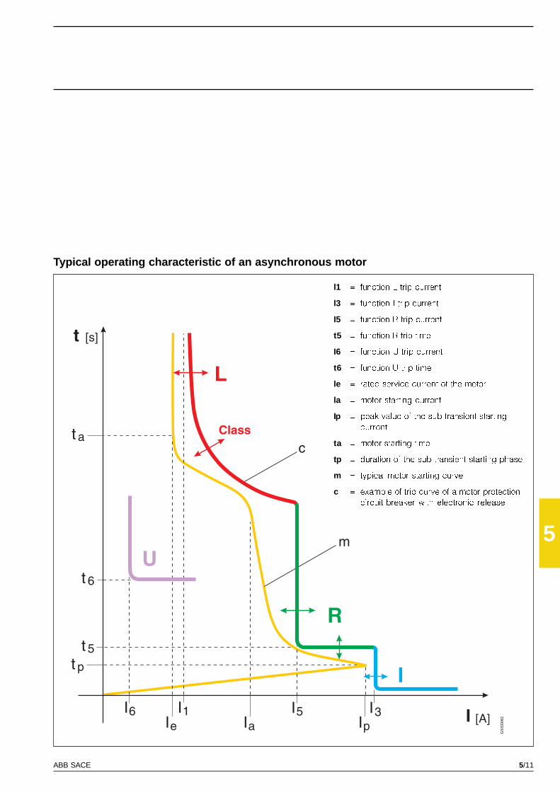
5/11ABB SACE
5
GS
IS00
82
Typical operating characteristic of an asynchronous motor
l1 = function L trip current
l3 = function I trip current
I5 = function R trip current
t5 = function R trip time
I6 = function U trip current
t6 = function U trip time
le = rated service current of the motor
la = motor starting current
Ip = peak value of the sub-transient starting
current
ta = motor starting time
tp = duration of the sub-transient starting phase
m = typical motor starting curve
c = example of trip curve of a motor protection
circuit-breaker with electronic release
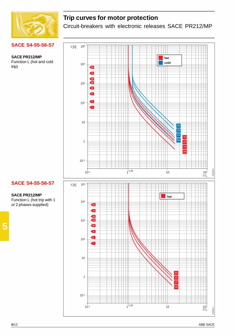
5/12 ABB SACE
5
SACE S4-S5-S6-S7
SACE S4-S5-S6-S7
104
t [s]
10-1
I / I1101
10
1
103
10-1
1,05 102
102
105
30
20
10
10A30
20
10
10A
104
t [s]
10-1
I / I1101
102
10
103
1
10-1
1,05 102
105
30
20
10
10A
GS
IS02
16G
SIS
0217
Trip curves for motor protectionCircuit-breakers with electronic releases SACE PR212/MP
SACE PR212/MPFunction L (hot and coldtrip)
SACE PR212/MPFunction L (hot trip with 1or 2 phases supplied)
hot
cold
hot
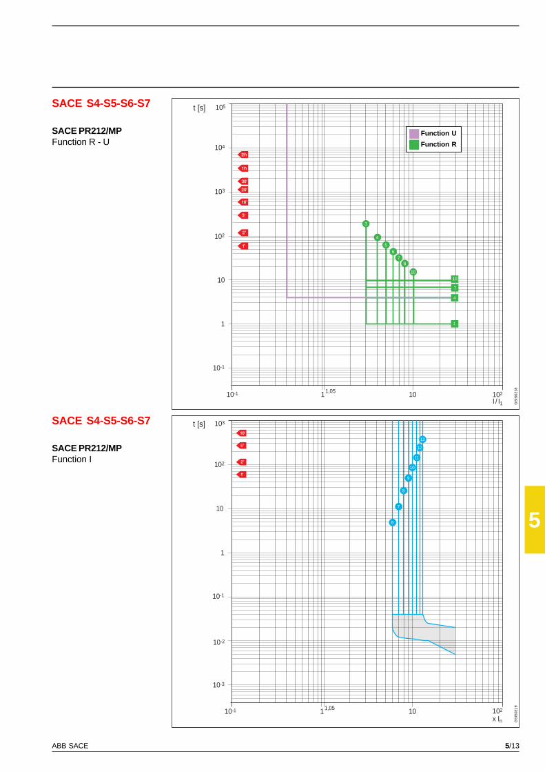
5/13ABB SACE
5
104
t [s]
10-1
I / I1101
10
1
103
10-1
1,05 102
102
105
10
87
6
5
4
3
7
10
4
1
102
t [s]
10-1
x In101
1
10
10-1
1,05 102
10-2
10-3
103
13
12
11
10
9
8
7
6
SACE S4-S5-S6-S7
SACE S4-S5-S6-S7
GS
IS02
18G
SIS
0219
SACE PR212/MPFunction R - U
SACE PR212/MPFunction I
Function U
Function R
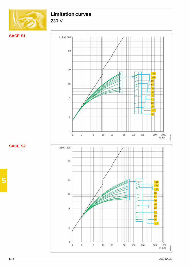
5/14 ABB SACE
5
SACE S1
SACE S2
1
Ip [kA]
10
1
20
50
2
5
100
1Is [kA]
2 5 10 20 50 100 200 500 1000
100
125
80
63
50
40
32
25
20
16
12,5
10
Ip [kA]
10
1
20
50
2
5
100
1Is [kA]
2 5 10 20 50 100 200 500 1000
160
125
100
80
63
50
40
32
25
20
16
12,5
GS
IS02
20G
SIS
0221
Limitation curves230 V
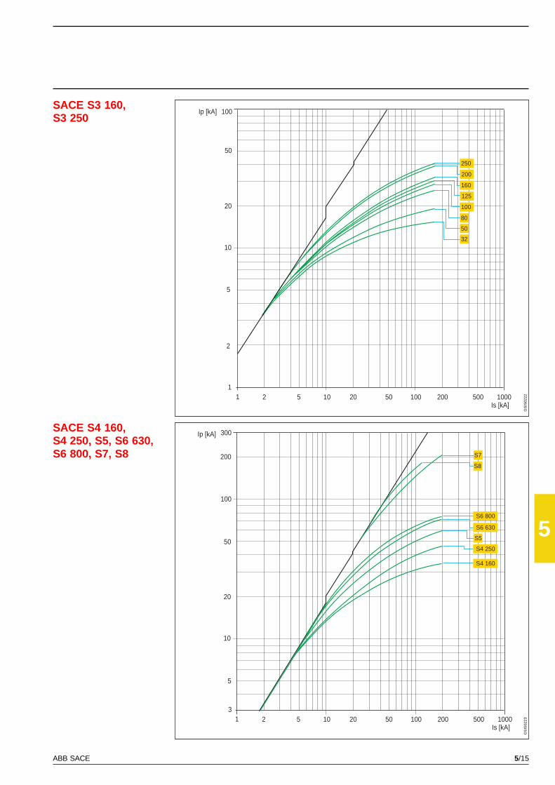
5/15ABB SACE
5
SACE S3 160,S3 250
SACE S4 160,S4 250, S5, S6 630,S6 800, S7, S8
Ip [kA]
10
1
20
50
2
5
100
1Is [kA]
2 5 10 20 50 100 200 500 1000
200
250
160
125
100
80
50
32
300Ip [kA]
10
3
20
50
5
100
1Is [kA]
2 5 10 20 50 100 200 500 1000
200
S4 160
S4 250
S6 630
S6 800
S7
S8
S5
GS
IS02
22G
SIS
0223
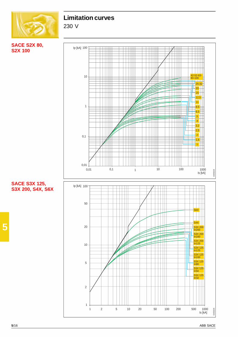
5/16 ABB SACE
5
SACE S2X 80,S2X 100
SACE S3X 125,S3X 200, S4X, S6X
Ip [kA]
10
10
0,01 100
1
100
1Is [kA]
1000
0,1
0,010,1
20
16
12,5
11
8,5
6,5
5
4
3,2
2,5
2
1,6
1
42-52-63-80-100
25-32
Ip [kA]
10
1
20
50
2
5
100
1Is [kA]
2 5 10 20 50 100 200 500 1000
S3X 125In80
S3X 125In100
S3X 125In125
S3X 200In125
S3X 200In160
S3X 200In200
S4X
S6X
S3X 125In50
S3X 125In32
GS
IS02
24G
SIS
0225
Limitation curves230 V

5/17ABB SACE
5
SACE S1
SACE S2 Ip [kA]
10
1
20
50
2
5
100
Is [kA]2 5 10 20 50 100 200 500 10001
160
125
100
40
50
32
25
20
16
12,5
80
63
Ip [kA]
10
1
20
50
2
5
100
1Is [kA]
2 5 10 20 50 100 200 500 1000
125
100
80
32
40
50
63
25
20
16
12,5
10
GS
IS02
26G
SIS
0227
Limitation curves400-440 V
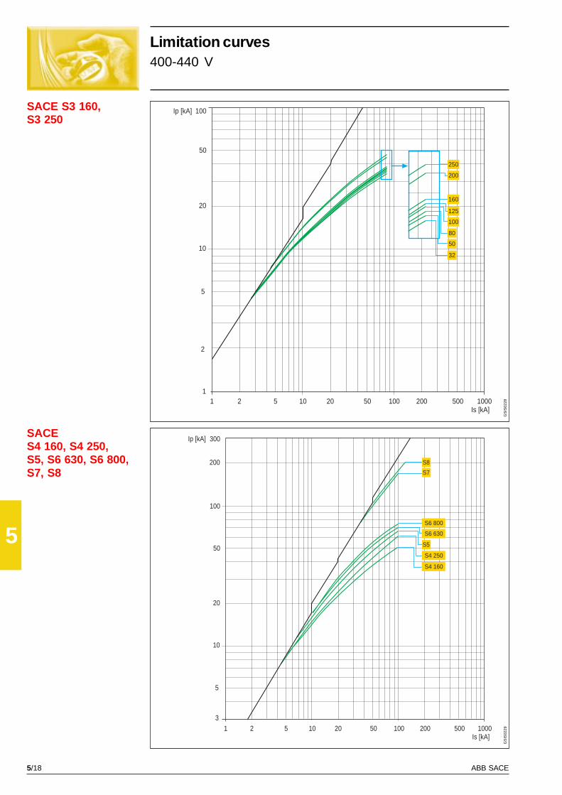
5/18 ABB SACE
5
SACE S3 160,S3 250
SACES4 160, S4 250,S5, S6 630, S6 800,S7, S8
Ip [kA]
10
1
20
50
2
5
100
Is [kA]2 5 10 20 50 100 200 500 10001
200
250
160
125
100
80
50
32
Ip [kA]
10
20
50
5
100
200
Is [kA]2 5 10 20 50 100 200 500 10001
3
300
S5
S6 630
S4 250
S4 160
S7
S8
S6 800
GS
IS02
28G
SIS
0229
Limitation curves400-440 V
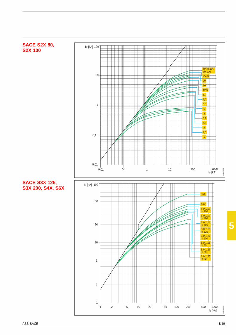
5/19ABB SACE
5
SACE S2X 80,S2X 100
SACE S3X 125,S3X 200, S4X, S6X
Ip [kA]
Is [kA]1
10
10 100
1
0,1
100
0,1
0,0110000,01
25-32
42-52-63-80-100
16
20
12,5
11
8,5
6,5
5
4
3,2
2,5
1
2
1,6
Ip [kA]
10
1
20
50
2
5
100
Is [kA]2 5 10 20 50 100 200 500 10001
S3X 125In 32
S3X 125In 50
S3X 125In 80
S3X 125In 100
S3X 125In 125
S3X 200In 125
S3X 200In 160
S3X 200In 200
S4X
S6X
GS
IS02
30G
SIS
0231
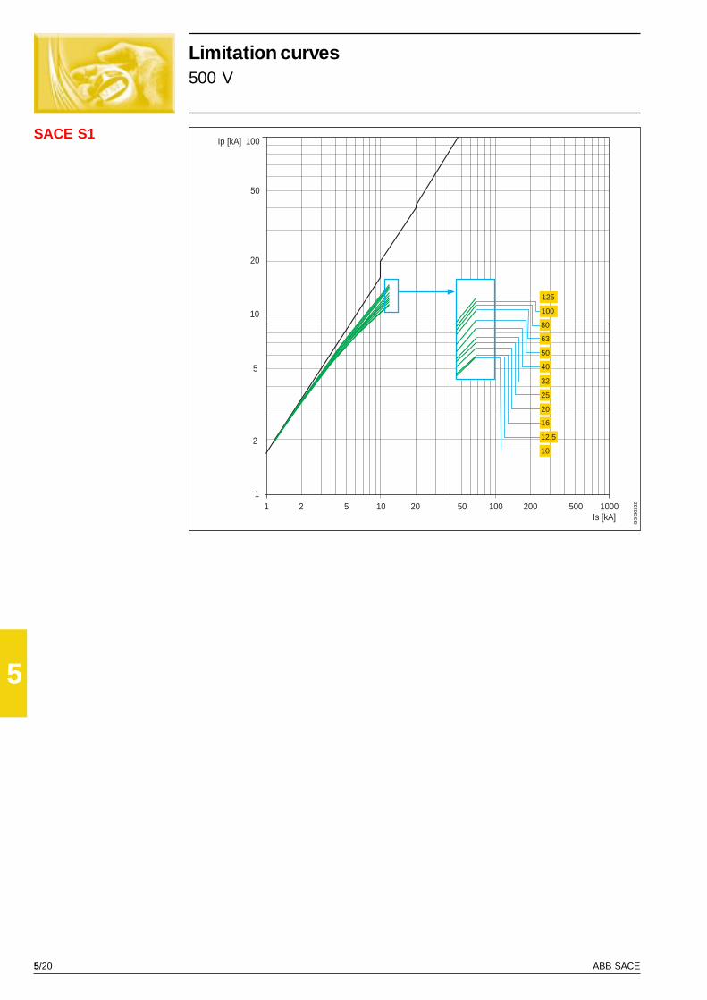
5/20 ABB SACE
5
SACE S1Ip [kA]
10
1
20
50
2
5
100
Is [kA]2 5 10 20 50 100 200 500 10001
10
25
63
80
16
20
125
100
12,5
50
40
32
GS
IS02
32
Limitation curves500 V

5/21ABB SACE
5
SACE S2
SACE S3 160,S3 250
Ip [kA]
10
1
20
50
2
5
100
Is [kA]2 5 10 20 50 100 200 500 10001
25
32
40
50
63
80
100
125
160
16
20
12,5
Ip [kA]
10
1
20
50
2
5
100
Is [kA]2 5 10 20 50 100 200 500 10001
50
32
80
100
125
160
200
250G
SIS
0233
GS
IS02
34
Limitation curves690 V

5/22 ABB SACE
5
SACE S2X 80,S2X 100
Ip [kA]
10
20
50
5
100
200
Is [kA]2 5 10 20 50 100 200 500 10001
300
S8
S6 630
S6 800
S5
S4 250
S4 160
S7
Ip [kA]
10
1
Is [kA]1 10010 10000,01
0,01
0,1
0,1
100
1,6
2
2,5
1
3,2
8,5
6,5
5
4
11
16
20
25-32
42-52-63-80-100
12,5
SACES4 160, S4 250, S5,S6 630, S6 800, S7,S8
GS
IS02
35G
SIS
0236
Limitation curves690 V
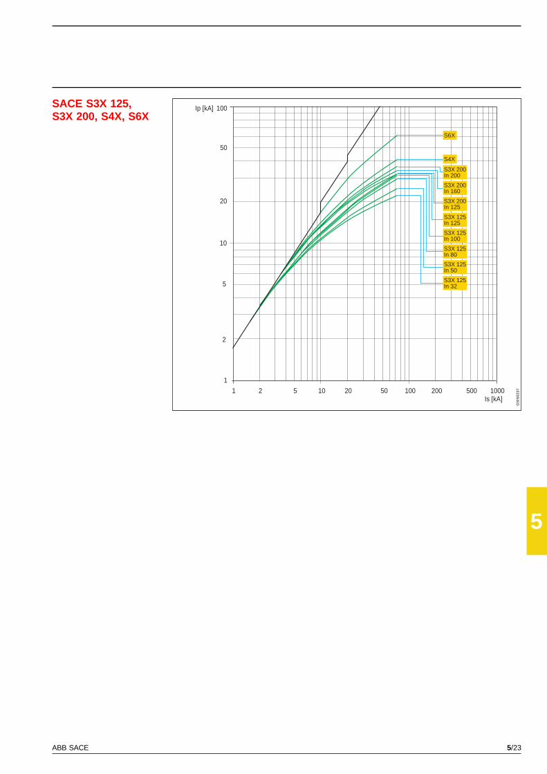
5/23ABB SACE
5
SACE S3X 125,S3X 200, S4X, S6X
Ip [kA]
10
1
20
50
2
5
100
Is [kA]2 5 10 20 50 100 200 500 10001
S3X 125In 32
S3X 125In 50
S3X 125In 80
S3X 125In 100
S3X 125In 125
S3X 200In 125
S3X 200In 160
S3X 200In 200
S6X
S4X
GS
IS02
37
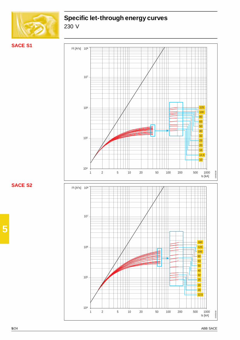
5/24 ABB SACE
5
SACE S1
SACE S2
I2t [A2s]
105
104
106
108
Is [kA]2 5 10 20 50 100 200 500 10001
107
12,5
16
20
25
32
40
50
63
80
100
125
10
I2t [A2s]
105
104
106
108
Is [kA]2 5 10 20 50 100 200 500 10001
107
12,5
160
125
100
80
50
63
40
32
16
20
25
GS
IS02
38G
SIS
0239
Specific let-through energy curves230 V
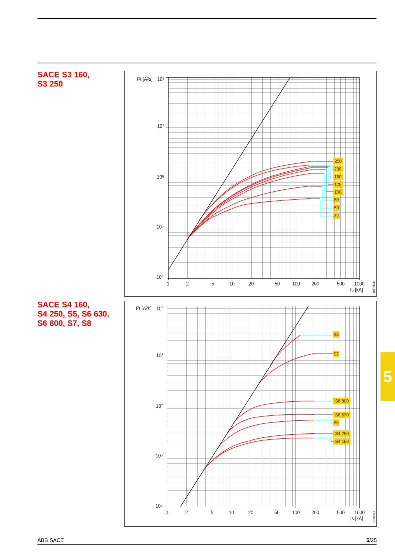
5/25ABB SACE
5
SACE S3 160,S3 250
SACE S4 160,S4 250, S5, S6 630,S6 800, S7, S8
I2t [A2s]
105
104
106
108
Is [kA]2 5 10 20 50 100 200 500 10001
107
250
160
125
100
200
80
50
32
I2t [A2s]
106
105
107
109
108
Is [kA]2 5 10 20 50 100 200 500 10001
S8
S4 250
S4 160
S6 800
S7
S5
S6 630
GS
IS02
40G
SIS
0241
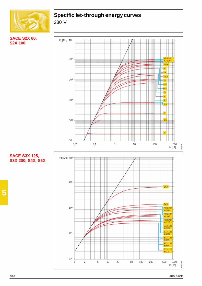
5/26 ABB SACE
5
SACE S2X 80,S2X 100
SACE S3X 125,S3X 200, S4X, S6X
10
I2t [A2s]
104
103
105
106
Is [kA]0,1 1 10010 10000,01
102
1
2
2,5
1,6
16
20
25-32
42-52-63-80-100
12,5
11
8,5
6,5
5
4
3,2
I2t [A2s]
105
104
106
108
107
Is [kA]2 5 10 20 50 100 200 500 10001
S3X 125In 50
S3X 125In 80
S3X 125In 100
S3X 125In 125
S3X 200In 125
S3X 200In 160
S3X 200In 200
S3X 125In 32
S6X
S4X
GS
IS02
42G
SIS
0243
Specific let-through energy curves230 V
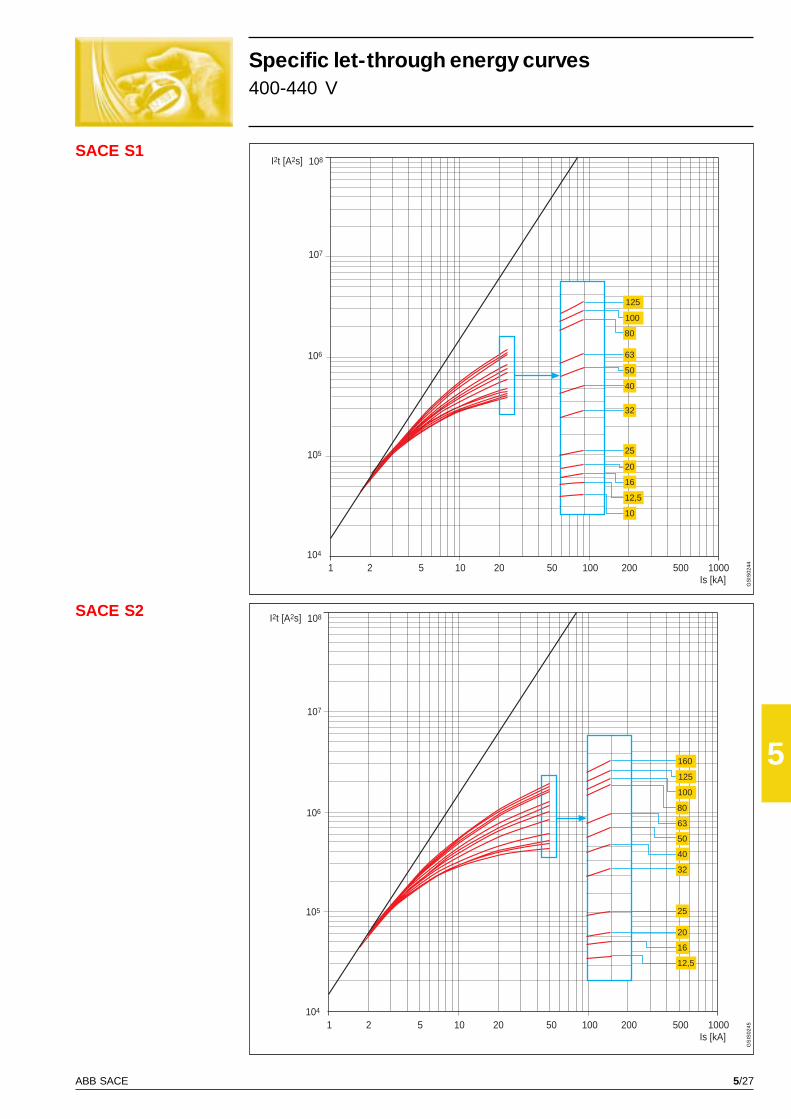
5/27ABB SACE
5
SACE S1
SACE S2 I2t [A2s]
105
104
106
108
107
Is [kA]2 5 10 20 50 100 200 500 10001
12,5
16
20
25
80
100
160
125
63
50
32
40
I2t [A2s]
105
104
106
108
107
Is [kA]2 5 10 20 50 100 200 500 10001
10
12,5
16
20
25
32
40
50
63
80
125
100
GS
IS02
44G
SIS
0245
Specific let-through energy curves400-440 V

5/28 ABB SACE
5
SACE S3 160,S3 250
SACE S4 160,S4 250, S5, S6 630,S6 800, S7, S8
I2t [A2s]
105
104
106
108
107
Is [kA]2 5 10 20 50 100 200 500 10001
200
160
125
100
80
50
32
250
I2t [A2s]
106
105
107
109
108
Is [kA]2 5 10 20 50 100 200 500 10001
S6 630
S4 250
S6 800
S8
S7
S5
S4 160
GS
IS02
46G
SIS
0247
Specific let-through energy curves400-440 V
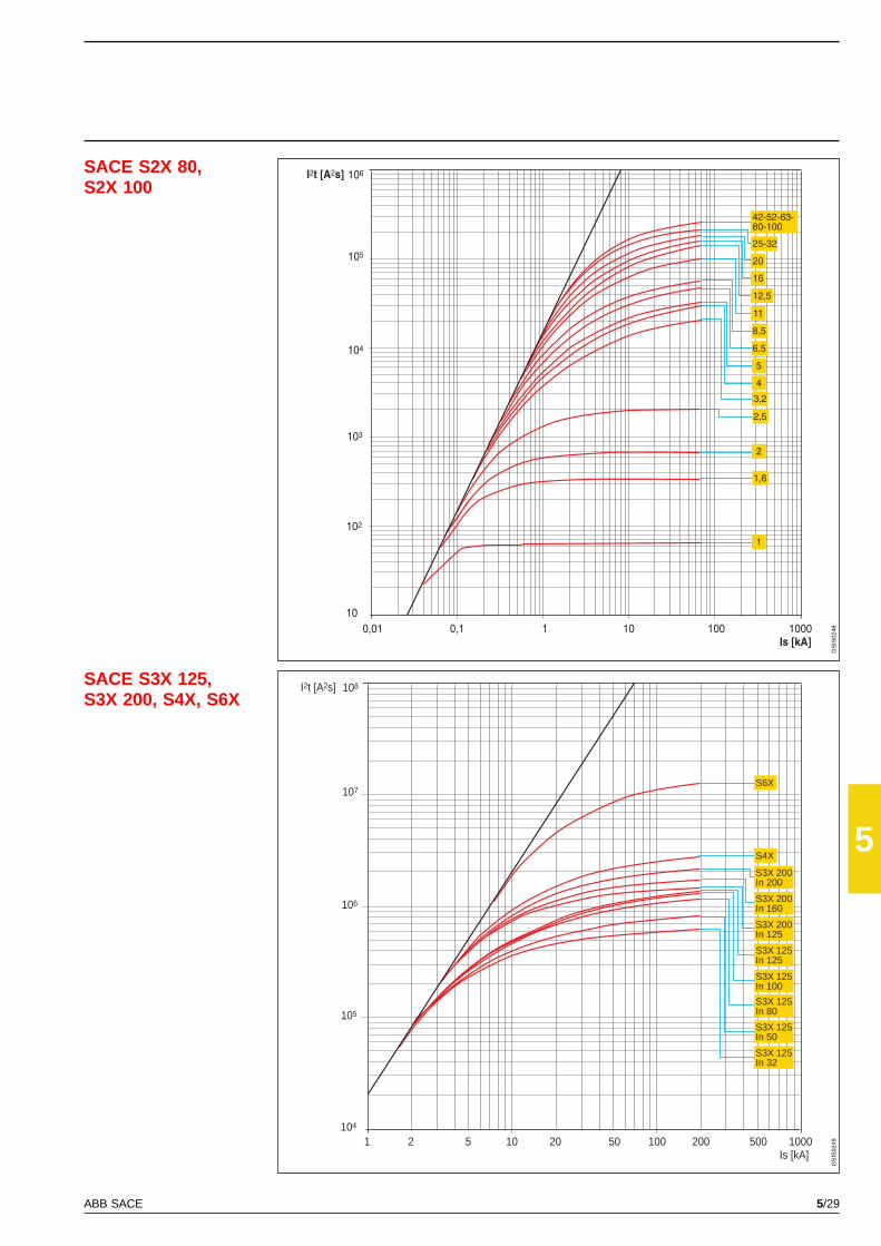
5/29ABB SACE
5
SACE S2X 80,S2X 100
SACE S3X 125,S3X 200, S4X, S6X
I2t [A2s]
102
10
103
106
104
Is [kA]0,1 1 10010 10000,01
105
1
2
1,6
8,5
20
25-32
42-52-63-80-100
16
12,5
11
6,5
5
4
3,2
2,5
I2t [A2s]
105
104
106
108
107
Is [kA]2 5 10 20 50 100 200 500 10001
S3X 125In 80
S3X 125In 100
S3X 125In 125
S3X 200In 125
S3X 200In 200
S3X 200In 160
S3X 125In 50
S3X 125In 32
S6X
S4X
GS
IS02
48G
SIS
0249

5/30 ABB SACE
5
SACE S1I2t [A2s]
105
104
106
108
107
Is [kA]2 5 10 20 50 100 200 500 10001
63
80
125
100
50
40
32
25
20
16
12,5
10
GS
IS02
50
Specific let-through energy curves500 V
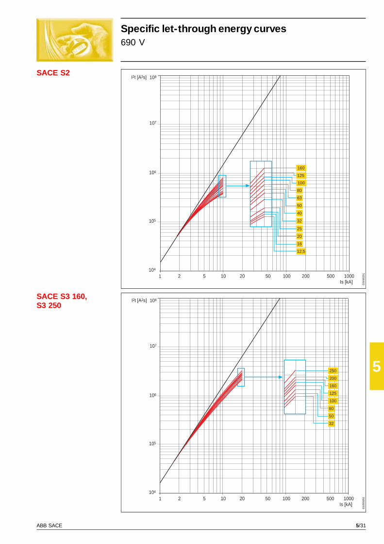
5/31ABB SACE
5
SACE S3 160,S3 250
SACE S2I2t [A2s]
105
104
106
108
107
Is [kA]2 5 10 20 50 100 200 500 10001
40
50
63
80
100
125
160
32
25
20
16
12,5
Is [kA]2 5 10 20 50 100 200 500 10001
I2t [A2s]
105
104
106
108
107
100
125
160
200
250
80
50
32
GS
IS02
51G
SIS
0252
Specific let-through energy curves690 V
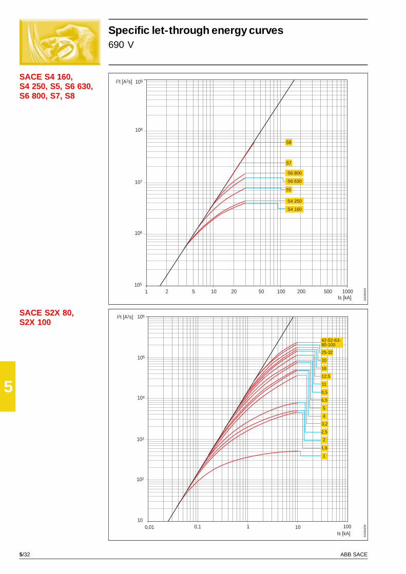
5/32 ABB SACE
5
SACE S2X 80,S2X 100
SACE S4 160,S4 250, S5, S6 630,S6 800, S7, S8
I2t [A2s]
105
107
109
108
Is [kA]2 5 10 20 50 100 200 500 10001
106
S5
S4 160
S4 250
S6 630
S6 800
S7
S8
0,01Is [kA]
10
105
10100
104
102
103
10,1
I2t [A2s] 106
12,5
16
20
25-32
42-52-63-80-100
11
8,5
6,5
5
4
3,2
2,5
2
1,6
1
GS
IS02
53G
SIS
0254
Specific let-through energy curves690 V
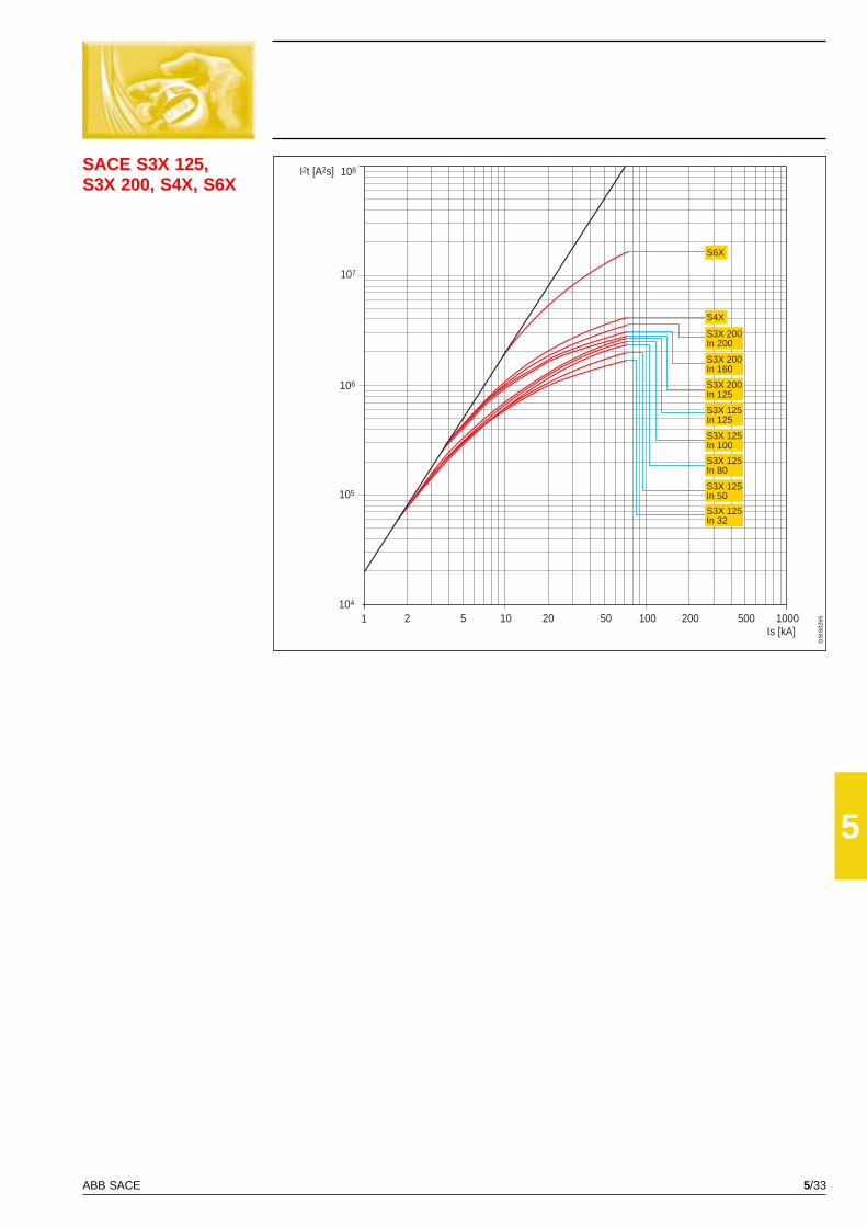
5/33ABB SACE
5
SACE S3X 125,S3X 200, S4X, S6X
Is [kA]2 5 10 20 50 100 200 500 10001
I2t [A2s]
105
104
106
108
107
S3X 200In 200
S3X 200In 160
S3X 200In 125
S3X 125In 125
S3X 125In 100
S3X 125In 80
S3X 125In 50
S3X 125In 32
S6X
S4X
GS
IS02
55

5/34 ABB SACE
5
SACE S4 250
GS
IS02
56G
SIS
0257
SACE S4 160
Temperature performanceCircuit-breakers with electronic releases
Plug-in - Withdrawableup to 40 °C 50 °C 60 °C 70 °C
Imax [A] I1 Imax [A] I1 Imax [A] I1 Imax [A] I1
Front flat bar 160 1 160 1 160 1 152 0.95
Front for cables 160 1 160 1 160 1 152 0.95
Rear for cables 160 1 160 1 160 1 144 0.9
Rear threaded 160 1 160 1 160 1 144 0.9
Plug-in - Withdrawableup to 40 °C 50 °C 60 °C 70 °C
Imax [A] I1 Imax [A] I1 Imax [A] I1 Imax [A] I1
Front flat bar 250 1 250 1 250 1 225 0.9
Front for cables 250 1 250 1 250 1 225 0.9
Rear for cables 250 1 250 1 250 1 200 0.8
Rear threaded 250 1 250 1 250 1 200 0.8
Fixedup to 40 °C 50 °C 60 °C 70 °C
Imax [A] I1 Imax [A] I1 Imax [A] I1 Imax [A] I1
Front flat bar 160 1 160 1 160 1 160 1
Front for cables 160 1 160 1 160 1 160 1
Rear for cables 160 1 160 1 160 1 152 0.95
Rear threaded 160 1 160 1 160 1 152 0.95
Fixedup to 40 °C 50 °C 60 °C 70 °C
Imax [A] I1 Imax [A] I1 Imax [A] I1 Imax [A] I1
Front flat bar 250 1 250 1 250 1 237.5 0.95
Front for cables 250 1 250 1 250 1 237.5 0.95
Rear for cables 250 1 250 1 250 1 225 0.9
Rear threaded 250 1 250 1 250 1 225 0.9
Front flat barFront for cables
Rear for cablesRear threaded
Front flat barFront for cables
Rear for cablesRear threaded
Front flat barFront for cables
Rear for cablesRear threaded
Front flat barFront for cables
Rear for cablesRear threaded

5/35ABB SACE
5
SACE S5 400
SACE S5 630
GS
IS02
58G
SIS
0259
Plug-in - Withdrawableup to 40 °C 50 °C 60 °C 70 °C
Imax [A] I1 Imax [A] I1 Imax [A] I1 Imax [A] I1
Front flat bar 400 1 400 1 400 1 380 0.95
Front for cables 400 1 400 1 380 0.95 360 0.9
Rear for cables 400 1 400 1 380 0.95 360 0.9
Rear threaded 400 1 380 0.95 360 0.9 320 0.8
Withdrawableup to 40 °C 50 °C 60 °C 70 °C
Imax [A] I1 Imax [A] I1 Imax [A] I1 Imax [A] I1
Front flat bar 630 1 504 0.8 441 0.7 378 0.6
Rear flat bar 630 1 567 0.9 504 0.8 441 0.7
Rear threaded 630 1 441 0.7 378 0.6 315 0.5
Fixedup to 40 °C 50 °C 60 °C 70 °C
Imax [A] I1 Imax [A] I1 Imax [A] I1 Imax [A] I1
Front flat bar 400 1 400 1 400 1 380 0.95
Front for cables 400 1 400 1 400 1 380 0.9
Rear for cables 400 1 400 1 400 1 360 0.9
Rear threaded 400 1 400 1 400 1 320 0.8
Fixedup to 40 °C 50 °C 60 °C 70 °C
Imax [A] I1 Imax [A] I1 Imax [A] I1 Imax [A] I1
Front flat bar 630 1 598.5 0.95 567 0.9 504 0.8
Front for cables 630 1 567 0.9 504 0.8 441 0.7
Rear threaded 630 1 504 0.8 441 0.7 378 0.6
Front flat bar
Front for cablesRear for cables
Rear threaded
Front for cablesRear for cables
Rear threaded
Front flat bar
Front for cables
Rear threaded
Rear flat bar
Front flat bar
Rear threaded
Front flat bar
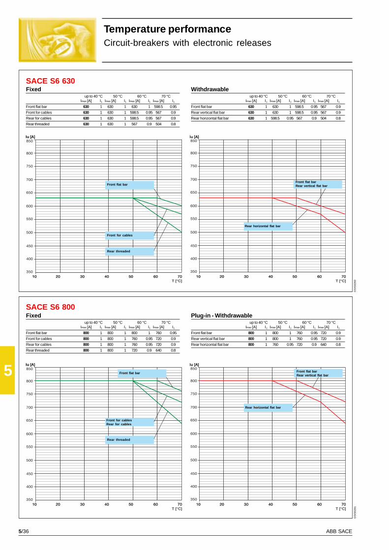
5/36 ABB SACE
5
SACE S6 630
SACE S6 800
GS
IS02
60G
SIS
0261
Temperature performanceCircuit-breakers with electronic releases
Withdrawableup to 40 °C 50 °C 60 °C 70 °C
Imax [A] I1 Imax [A] I1 Imax [A] I1 Imax [A] I1
Front flat bar 630 1 630 1 598.5 0.95 567 0.9
Rear vertical flat bar 630 1 630 1 598.5 0.95 567 0.9
Rear horizontal flat bar 630 1 598.5 0.95 567 0.9 504 0.8
Plug-in - Withdrawableup to 40 °C 50 °C 60 °C 70 °C
Imax [A] I1 Imax [A] I1 Imax [A] I1 Imax [A] I1
Front flat bar 800 1 800 1 760 0.95 720 0.9
Rear vertical flat bar 800 1 800 1 760 0.95 720 0.9
Rear horizontal flat bar 800 1 760 0.95 720 0.9 640 0.8
Front flat bar
Front for cables
Rear threaded
Front flat barRear vertical flat bar
Rear horizontal flat bar
Front flat bar
Front for cablesRear for cables
Rear threaded
Front flat barRear vertical flat bar
Rear horizontal flat bar
Fixedup to 40 °C 50 °C 60 °C 70 °C
Imax [A] I1 Imax [A] I1 Imax [A] I1 Imax [A] I1
Front flat bar 630 1 630 1 630 1 598.5 0.95
Front for cables 630 1 630 1 598.5 0.95 567 0.9
Rear for cables 630 1 630 1 598.5 0.95 567 0.9
Rear threaded 630 1 630 1 567 0.9 504 0.8
Fixedup to 40 °C 50 °C 60 °C 70 °C
Imax [A] I1 Imax [A] I1 Imax [A] I1 Imax [A] I1
Front flat bar 800 1 800 1 800 1 760 0.95
Front for cables 800 1 800 1 760 0.95 720 0.9
Rear for cables 800 1 800 1 760 0.95 720 0.9
Rear threaded 800 1 800 1 720 0.9 640 0.8
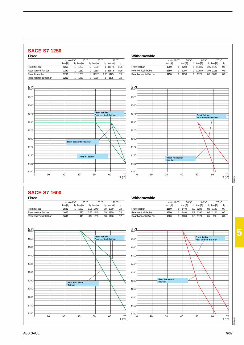
5/37ABB SACE
5
SACE S7 1250
SACE S7 1600
GS
IS02
62G
SIS
0263
Withdrawableup to 40 °C 50 °C 60 °C 70 °C
Imax [A] I1 Imax [A] I1 Imax [A] I1 Imax [A] I1
Front flat bar 1250 1 1250 1 1187.5 0.95 1125 0.9
Rear vertical flat bar 1250 1 1250 1 1187.5 0.95 1125 0.9
Rear horizontal flat bar 1250 1 1250 1 1125 0.9 1000 0.8
Withdrawableup to 40 °C 50 °C 60 °C 70 °C
Imax [A] I1 Imax [A] I1 Imax [A] I1 Imax [A] I1
Front flat bar 1600 1 1440 0.9 1280 0.8 1120 0.7
Rear vertical flat bar 1600 1 1440 0.9 1280 0.8 1120 0.7
Rear horizontal flat bar 1600 1 1280 0.8 1120 0.7 906 0.6
Front flat barRear vertical flat bar
Rear horizontal flat bar
Front for cables Rear horizontalflat bar
Front flat barRear vertical flat bar
Front flat barRear vertical flat bar
Rear horizontalflat barRear horizontal
flat bar
Fixedup to 40 °C 50 °C 60 °C 70 °C
Imax [A] I1 Imax [A] I1 Imax [A] I1 Imax [A] I1
Front flat bar 1250 1 1250 1 1250 1 1187.5 0.95
Rear vertical flat bar 1250 1 1250 1 1250 1 1187.5 0.95
Front for cables 1250 1 1250 1 1187.5 0.95 1125 0.9
Rear horizontal flat bar 1250 1 1250 1 1250 1 1125 0.9
Fixedup to 40 °C 50 °C 60 °C 70 °C
Imax [A] I1 Imax [A] I1 Imax [A] I1 Imax [A] I1
Front flat bar 1600 1 1520 0.95 1440 0.9 1280 0.8
Rear vertical flat bar 1600 1 1520 0.95 1440 0.9 1280 0.8
Rear horizontal flat bar 1600 1 1440 0.9 1280 0.8 1120 0.7
Front flat barRear vertical flat bar
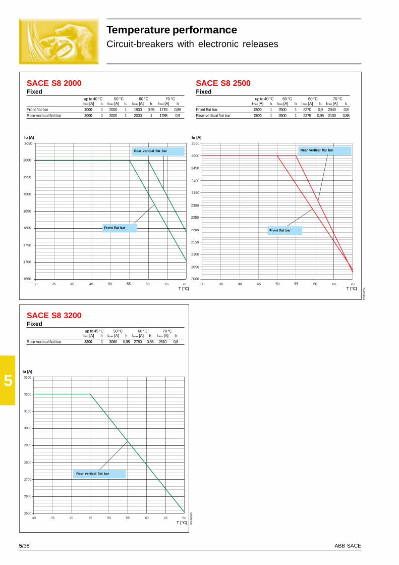
5/38 ABB SACE
5
SACE S8 2000 SACE S8 2500
SACE S8 3200
30 35 40 45 50 55 60 65 70
2550
2500
2450
2250
2050
2000
2150
2100
2400
2200
7030 35 40 45 50 55 60 65
2050
2000
1950
1900
1800
1700
1650
1850
1750
2300
2350
7030 35 40 45 50 55 60 65
3300
3200
3100
3000
2800
2600
2500
2900
2700
GS
IS02
64
GS
IS02
65
Temperature performanceCircuit-breakers with electronic releases
Front flat bar
Rear vertical flat bar
Front flat bar
Rear vertical flat bar
Fixedup to 40 °C 50 °C 60 °C 70 °C
Imax [A] I1 Imax [A] I1 Imax [A] I1 Imax [A] I1
Front flat bar 2000 1 2000 1 1900 0,95 1715 0,85
Rear vertical flat bar 2000 1 2000 1 2000 1 1785 0,9
Fixedup to 45 °C 50 °C 60 °C 70 °C
Imax [A] I1 Imax [A] I1 Imax [A] I1 Imax [A] I1
Rear vertical flat bar 3200 1 3060 0,95 2780 0,85 2510 0,8
Fixedup to 40 °C 50 °C 60 °C 70 °C
Imax [A] I1 Imax [A] I1 Imax [A] I1 Imax [A] I1
Front flat bar 2500 1 2500 1 2270 0,9 2040 0,8
Rear vertical flat bar 2500 1 2500 1 2375 0,95 2130 0,85
Rear vertical flat bar
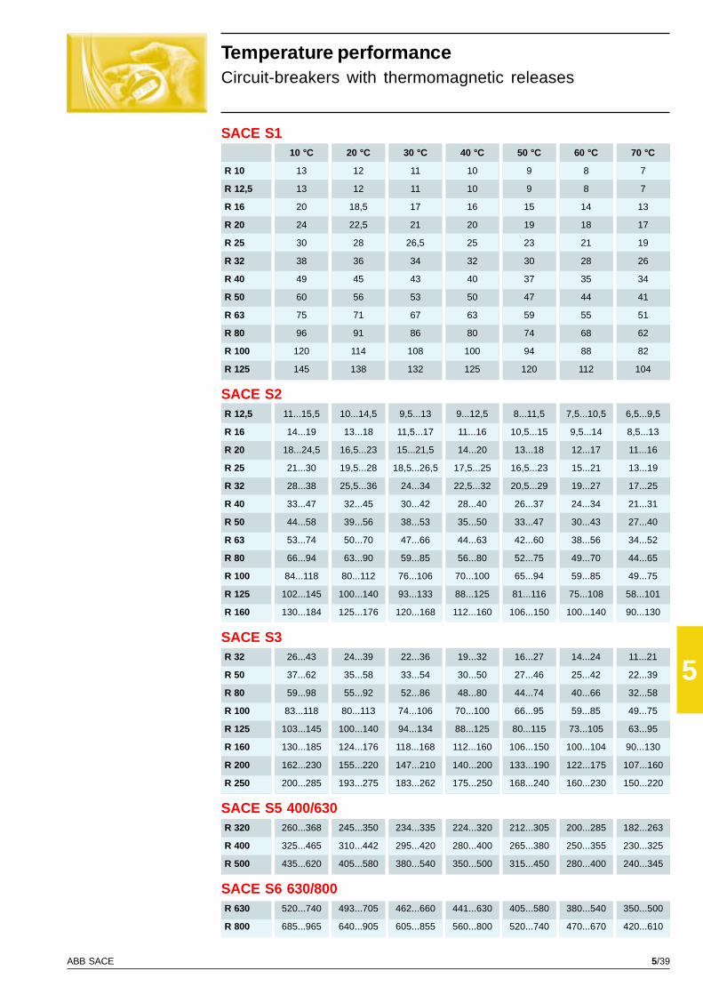
5/39ABB SACE
5
SACE S110 °C 20 °C 30 °C 40 °C 50 °C 60 °C 70 °C
R 10 13 12 11 10 9 8 7
R 12,5 13 12 11 10 9 8 7
R 16 20 18,5 17 16 15 14 13
R 20 24 22,5 21 20 19 18 17
R 25 30 28 26,5 25 23 21 19
R 32 38 36 34 32 30 28 26
R 40 49 45 43 40 37 35 34
R 50 60 56 53 50 47 44 41
R 63 75 71 67 63 59 55 51
R 80 96 91 86 80 74 68 62
R 100 120 114 108 100 94 88 82
R 125 145 138 132 125 120 112 104
SACE S2R 12,5 11...15,5 10...14,5 9,5...13 9...12,5 8...11,5 7,5...10,5 6,5...9,5
R 16 14...19 13...18 11,5...17 11...16 10,5...15 9,5...14 8,5...13
R 20 18...24,5 16,5...23 15...21,5 14...20 13...18 12...17 11...16
R 25 21...30 19,5...28 18,5...26,5 17,5...25 16,5...23 15...21 13...19
R 32 28...38 25,5...36 24...34 22,5...32 20,5...29 19...27 17...25
R 40 33...47 32...45 30...42 28...40 26...37 24...34 21...31
R 50 44...58 39...56 38...53 35...50 33...47 30...43 27...40
R 63 53...74 50...70 47...66 44...63 42...60 38...56 34...52
R 80 66...94 63...90 59...85 56...80 52...75 49...70 44...65
R 100 84...118 80...112 76...106 70...100 65...94 59...85 49...75
R 125 102...145 100...140 93...133 88...125 81...116 75...108 58...101
R 160 130...184 125...176 120...168 112...160 106...150 100...140 90...130
SACE S3R 32 26...43 24...39 22...36 19...32 16...27 14...24 11...21
R 50 37...62 35...58 33...54 30...50 27...46 25...42 22...39
R 80 59...98 55...92 52...86 48...80 44...74 40...66 32...58
R 100 83...118 80...113 74...106 70...100 66...95 59...85 49...75
R 125 103...145 100...140 94...134 88...125 80...115 73...105 63...95
R 160 130...185 124...176 118...168 112...160 106...150 100...104 90...130
R 200 162...230 155...220 147...210 140...200 133...190 122...175 107...160
R 250 200...285 193...275 183...262 175...250 168...240 160...230 150...220
SACE S5 400/630R 320 260...368 245...350 234...335 224...320 212...305 200...285 182...263
R 400 325...465 310...442 295...420 280...400 265...380 250...355 230...325
R 500 435...620 405...580 380...540 350...500 315...450 280...400 240...345
SACE S6 630/800R 630 520...740 493...705 462...660 441...630 405...580 380...540 350...500
R 800 685...965 640...905 605...855 560...800 520...740 470...670 420...610
Temperature performanceCircuit-breakers with thermomagnetic releases
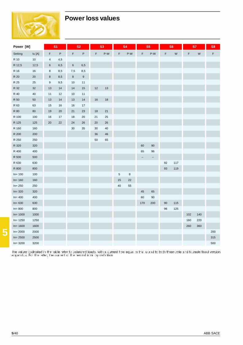
5/40 ABB SACE
5
S1 S2 S3 S4 S5 S6 S7 S8
Iu [A] F P F P F P-W F P-W F P-W F W F W F
R 10 10 4 4,5
R 12,5 12,5 6 6,5 6 6,5
R 16 16 8 8,5 7,5 8,5
R 20 20 8 8,5 8 9
R 25 25 9 9,5 10 11
R 32 32 13 14 14 15 12 13
R 40 40 11 12 10 11
R 50 50 13 14 13 14 16 18
R 63 63 15 16 16 17
R 80 80 19 20 21 23 18 21
R 100 100 16 17 18 20 21 25
R 125 125 20 22 24 26 20 26
R 160 160 30 35 30 40
R 200 200 36 46
R 250 250 50 65
R 320 320 60 90
R 400 400 65 96
R 500 500 – –
R 630 630 92 117
R 800 800 93 119
In= 100 100 5 8
In= 160 160 15 22
In= 250 250 40 55
In= 320 320 45 65
In= 400 400 60 90
In= 630 630 170 200 90 115
In= 800 800 96 125
In= 1000 1000 102 140
In= 1250 1250 160 220
In= 1600 1600 260 360
In= 2000 2000 200
In= 2500 2500 315
In= 3200 3200 500
Power loss values
The values indicated in the table refer to balanced loads, with a current flow equal to the Iu and to both three-pole and four-pole fixed versionapparatus. For the latter, the current of the neutral is nil by definition.
Power [W]
Setting
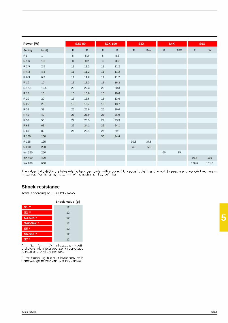
5/41ABB SACE
5
S2X 80 S2X 100 S3X S4X S6X
Iu [A] F P F P F P-W F P-W F W
R 1 1 8 8,2 8 8,2
R 1,6 1,6 8 8,2 8 8,2
R 2,5 2,5 11 11,2 11 11,2
R 4,3 4,3 11 11,2 11 11,2
R 6,3 6,3 11 11,2 11 11,2
R 10 10 16 16,3 16 16,3
R 12,5 12,5 20 20,3 20 20,3
R 16 16 10 10,6 10 10,6
R 20 20 13 13,6 13 13,6
R 25 25 13 13,7 13 13,7
R 32 32 26 26,6 26 26,6
R 40 40 26 26,9 26 26,9
R 50 50 22 23,3 22 23,3
R 63 63 22 24,1 22 24,1
R 80 80 26 29,1 26 29,1
R 100 100 30 34,4
R 125 125 30,8 37,8
R 200 200 48 58
In= 250 250 60 75
In= 400 400 80,4 101
In= 630 630 126,6 151,6
S1 ** 12
S2 ** 12
S3-S3X * 12
S4X-S4X * 12
S5 * 12
S6-S6X * 12
S7 * 12
Power [W]
Setting
The values indicated in the table refer to balanced loads, with a current flow equal to the Iu and to both three-pole and four-pole fixed versionapparatus. For the latter, the current of the neutral is nil by definition.
Shock resistanceTests according to IEC 60068-2-27
* for fixed/plug-in/withdrawable circuit-brakekers with motor operator, undervoltagerelease and auxiliary contacts
** for fixed/plug-in circuit-brakekers withundervoltage release and auxiliary contacts
Shock value [g]
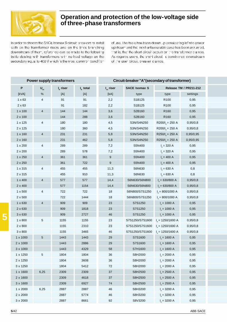
5/42 ABB SACE
5
[kVA] % [A] [A]
1 x 63 4 91 91
2 x 63 91 182
1 x 100 4 144 144
2 x 100 144 288
1 x 125 4 180 180
2 x 125 180 360
1 x 160 4 231 231
2 x 160 231 462
1 x 200 4 289 289
2 x 200 289 578
1 x 250 4 361 361
2 x 250 361 722
1 x 315 4 455 455
2 x 315 455 910
1 x 400 4 577 577
2 x 400 577 1154
1 x 500 4 722 722
2 x 500 722 1444
1 x 630 4 909 909
2 x 630 909 1818
3 x 630 909 2727
1 x 800 5 1155 1155
2 x 800 1155 2310
3 x 800 1155 3465
1 x 1000 5 1443 1443
2 x 1000 1443 2886
3 x 1000 1443 4329
1 x 1250 5 1804 1804
2 x 1250 1804 3608
3 x 1250 1804 5412
1 x 1600 6,25 2309 2309
2 x 1600 2309 4618
3 x 1600 2309 6927
1 x 2000 6,25 2887 2887
2 x 2000 2887 5774
3 x 2000 2887 8661
2,2 S1B125 R100 0,95
2,2 S1B125 R100 0,95
3,6 S2B160 R160 0,95
3,6 S2B160 R160 0,95
4,5 S3N/S4N250 R200/In = 250 A 0,95/0,8
4,5 S3N/S4N250 R200/In = 250 A 0,95/0,8
5,8 S3N/S4N250 R250/In = 250 A 0,95/0,95
5,8 S3N/S4N250 R250/In = 250 A 0,95/0,95
7,2 S5N400 In = 320 A 0,95
7,2 S5N400 In = 320 A 0,95
9 S5N400 In = 400 A 0,95
9 S5N400 In = 400 A 0,95
11,3 S6N630 In = 630 A 0,8
11,3 S6N630 In = 630 A 0,8
14,4 S6N630/S6N800 In = 630/800 A 0,95/0,8
14,4 S6N630/S6N800 In = 630/800 A 0,95/0,8
18 S6N800/S7S1250 In = 800/1000 A 0,95/0,8
18 S6N800/S7S1250 In = 800/1000 A 0,95/0,8
23 S7S1250 In = 1000 A 0,95
23 S7S1250 In = 1000 A 0,95
46 S7S1250 In = 1000 A 0,95
23 S7S1250/S7S1600 In = 1250/1600 A 0,95/0,8
23 S7S1250/S7S1600 In = 1250/1600 A 0,95/0,8
46 S7S1250/S7S1600 In = 1250/1600 A 0,95/0,8
29 S7S1600 In = 1600 A 0,95
29 S7S1600 In = 1600 A 0,95
58 S7H1600 In = 1600 A 0,95
36 S8H2000 In = 2000 A 0,95
36 S8H2000 In = 2000 A 0,95
72 S8H2000 In = 2000 A 0,95
37 S8H2500 In = 2500 A 0,95
37 S8H2500 In = 2500 A 0,95
74 S8H2500 In = 2500 A 0,95
46 S8H3200 In = 3200 A 0,95
46 S8H3200 In = 3200 A 0,95
92 S8V3200 In = 3200 A 0,95
Operation and protection of the low-voltage sideof three-phase transformers
In order to choose the SACE Isomax S circuit-breakers to install
both on the transformer risers and on the lines branching
downstream of them, reference can be made to the following
table dealing with transformers with no-load voltage on the
secondary equal to 400 V which is the most common condition
of use. The table has been drawn up considering infinite power
upstream and the most unfavourable case has been assumed,
that is, that the short circuit occurs on the transformer clamps.
As regards users, the short circuit is considered downstream
of the user circuit-breaker clamps.
Power supply transformers
P Ucc Ib riser I b total
Circuit-breaker "A"(secondary of transformer)
Icc riser SACE Isomax S Release TM / PR211-212
[kA] type type settings

5/43ABB SACE
5
GS
IS02
72
[kA] 32 A 63 A 125 A 160 A 250 A 400 A 630 A 800 A 1250 A 1600 A
2,2 S250 S250
4,4 S250 S250 S1B125
3,6 S250 S250 S1B125
7,2 S250 S250 S1B125
4,5 S250 S250 S1B125 S2B160
9 S250 S250 S1B125 S2B160
5,8 S250 S250 S1B125 S2B160
11,6 S1B125 S1B125 S1B125 S2B160 S3N250
7,2 S250 S250 S1B125 S2B160 S3N250
14,4 S1B125 S1B125 S1B125 S2B160 S3N250 S5N400
9 S250 S250 S1B125 S2B160 S3N250 –
18 S1N125 S1N125 S1N125 S2N160 S3N250 S5N400
11,3 S1B125 S1B125 S1B125 S2B160 S3N250 S5N400
22,6 S1N125 S1N125 S1N125 S2N160 S3N250 S5N400 S5N / S6N630
14,4 S1B125 S1B125 S1B125 S2B160 S3N250 S5N400 –
28,8 S2N160 S2N160 S2N160 S2N160 S3N250 S5N400 S5N / S6N630
18 S1N125 S1N125 S1N125 S2N160 S3N250 S5N400 S5N / S6N630
36 S2N160 S2N160 S2N160 S2N160 S3N250 S5N400 S5N / S6N630 S6N800
23 S1N125 S1N125 S1N125 S2N160 S3N250 S5N400 S5N / S6N630 S6N800
46 S2S160 S2S160 S2S160 S2S160 S3H250 S5H400 S5H / S6S630 S6S800 S7S1250
69 S2X100 S2X100 S3L160 S3L160 S3L250 S5L400 S5L / S6L630 S6L800 S7L1250
23 S1N125 S1N125 S1N125 S2N160 S3N250 S5N400 S5N / S6N630 S6N800 –
46 S2S160 S2S160 S2S160 S2S160 S3H250 S5H400 S5H / S6S630 S6S800 S7S1250
69 S2X100 S2X100 S3L160 S3L160 S3L250 S5L400 S5L / S6L630 S6L800 S7L1250
29 S2N160 S2N160 S2N160 S2N160 S3N250 S5N400 S5N / S6N630 S6N800 S7S1250
58 S2X100 S2X100 S3H160 S3H160 S3H250 S5H400 S5H / S6H630 S6H800 S7H1250 S7H1250
87 S4L160 S4L160 S4L160 S4L160 S4L250 S5L400 S5L/S6L630 S6L800 S7L1250 S7L1250
36 S2N160 S2N160 S2N160 S2N160 S3N250 S5N400 S5N/S6N630 S6N800 S7S1250 S7S1600
72 S3L160 S4L160 S3L160 S3L160 S3L250 S5L400 S5L/S6L630 S6L800 S7L1250 S7L1250
108 S3X125 S3X125(R80) S3X125 S3X200 S4X250 S6X400 S6X630 S8V2000 S8V2000 S8V2000
37 S2S160 S2S160 S2S160 S2S160 S3H250 S5H400 S5H/S6S630 S6S800 S7S1250 S7S1600
74 S3L160 S3L160(R80) S3L160 S3L160 S3L250 S5L400 S5L/S6L630 S6L800 S7L1250 S7L1600
111 S3X125 S3X125(R80) S3X125 S3X200 S4X250 S6X400 S6X630 S8V2000 S8V2000 S8V2000
46 S2S160 S2S160 S2S160 S2S160 S3H250 S5H400 S5H/S6S630 S6S800 S7S1250 S7S1600
92 S4L160 S4L160 S4L160 S4L160 S4L250 S5L400 S5L/S6L630 S6L800 S7L1250 S7L1600
138 S3X125 S3X125(R80) S3X125 S3X200 S4X250 S6X400 S6X630 – – –
Circuit-breaker "B" (user outgoing)
Icu user User rated current and type of circuit-breaker
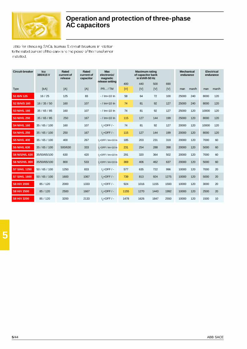
5/44 ABB SACE
5
S1 B/N 125 16 / 25 125 83 - / Im=10 In 58 64 72 100 25000 240 8000 120
S2 B/N/S 160 16 / 35 / 50 160 107 - / Im=10 In 74 81 92 127 25000 240 8000 120
S3 N/H/L 160 35 / 65 / 85 160 107 - / Im=10 In 74 81 92 127 25000 120 10000 120
S3 N/H/L 250 35 / 65 / 85 250 167 - / Im=10 In 115 127 144 199 25000 120 8000 120
S4 N/H/L 160 35 / 65 / 100 160 107 I3=OFF / - 74 81 92 127 20000 120 10000 120
S4 N/H/L 250 35 / 65 / 100 250 167 I3=OFF / - 115 127 144 199 20000 120 8000 120
S5 N/H/L 400 35 / 65 / 100 400 267 I3=OFF / Im=10 In 185 203 231 319 20000 120 7000 60
S5 N/H/L 630 35 / 65 / 100 500/630 333 I3=OFF / Im=10 In 231 254 288 398 20000 120 5000 60
S6 N/S/H/L 630 35/50/65/100 630 420 I3=OFF / Im=10 In 291 320 364 502 20000 120 7000 60
S6 N/S/H/L 800 35/50/65/100 800 533 I3=OFF / Im=10 In 369 406 462 637 20000 120 5000 60
S7 S/H/L 1250 50 / 65 / 100 1250 833 I3=OFF / - 577 635 722 996 10000 120 7000 20
S7 S/H/L 1600 50 / 65 / 100 1600 1067 I3=OFF / - 739 813 924 1275 10000 120 5000 20
S8 H/V 2000 85 / 120 2000 1333 I3=OFF / - 924 1016 1155 1593 10000 120 3000 20
S8 H/V 2500 85 / 120 2500 1667 I3=OFF / - 1155 1270 1443 1992 10000 120 2500 20
S8 H/V 3200 85 / 120 3200 2133 I3=OFF / - 1478 1626 1847 2550 10000 120 1500 10
Table for choosing SACE Isomax S circuit-breakers in relation
to the rated current of the bank and the power of the transformer
installed.
Operation and protection of three-phaseAC capacitors
Circuit-breaker Icu Rated Rated Max Maximum rating Mechanical Electrical380/415 V current of current of electronic/ of capacitor bank endurance endurance
release capacitor magnetic in kV AR-50 Hzrelease setting
400 440 500 690
Type [kA] [A] [A] PR... / TM [V] [V] [V] [V] man man/h man man/h
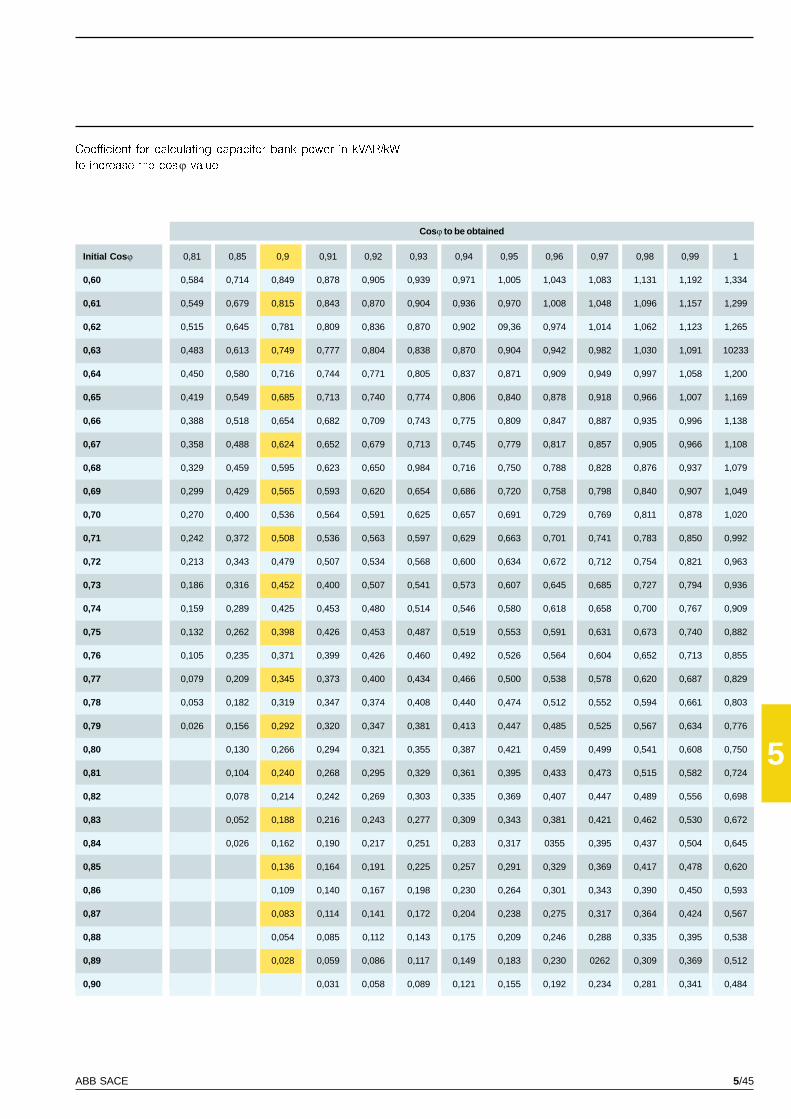
5/45ABB SACE
5
0,81 0,85 0,9 0,91 0,92 0,93 0,94 0,95 0,96 0,97 0,98 0,99 1
0,60 0,584 0,714 0,849 0,878 0,905 0,939 0,971 1,005 1,043 1,083 1,131 1,192 1,334
0,61 0,549 0,679 0,815 0,843 0,870 0,904 0,936 0,970 1,008 1,048 1,096 1,157 1,299
0,62 0,515 0,645 0,781 0,809 0,836 0,870 0,902 09,36 0,974 1,014 1,062 1,123 1,265
0,63 0,483 0,613 0,749 0,777 0,804 0,838 0,870 0,904 0,942 0,982 1,030 1,091 10233
0,64 0,450 0,580 0,716 0,744 0,771 0,805 0,837 0,871 0,909 0,949 0,997 1,058 1,200
0,65 0,419 0,549 0,685 0,713 0,740 0,774 0,806 0,840 0,878 0,918 0,966 1,007 1,169
0,66 0,388 0,518 0,654 0,682 0,709 0,743 0,775 0,809 0,847 0,887 0,935 0,996 1,138
0,67 0,358 0,488 0,624 0,652 0,679 0,713 0,745 0,779 0,817 0,857 0,905 0,966 1,108
0,68 0,329 0,459 0,595 0,623 0,650 0,984 0,716 0,750 0,788 0,828 0,876 0,937 1,079
0,69 0,299 0,429 0,565 0,593 0,620 0,654 0,686 0,720 0,758 0,798 0,840 0,907 1,049
0,70 0,270 0,400 0,536 0,564 0,591 0,625 0,657 0,691 0,729 0,769 0,811 0,878 1,020
0,71 0,242 0,372 0,508 0,536 0,563 0,597 0,629 0,663 0,701 0,741 0,783 0,850 0,992
0,72 0,213 0,343 0,479 0,507 0,534 0,568 0,600 0,634 0,672 0,712 0,754 0,821 0,963
0,73 0,186 0,316 0,452 0,400 0,507 0,541 0,573 0,607 0,645 0,685 0,727 0,794 0,936
0,74 0,159 0,289 0,425 0,453 0,480 0,514 0,546 0,580 0,618 0,658 0,700 0,767 0,909
0,75 0,132 0,262 0,398 0,426 0,453 0,487 0,519 0,553 0,591 0,631 0,673 0,740 0,882
0,76 0,105 0,235 0,371 0,399 0,426 0,460 0,492 0,526 0,564 0,604 0,652 0,713 0,855
0,77 0,079 0,209 0,345 0,373 0,400 0,434 0,466 0,500 0,538 0,578 0,620 0,687 0,829
0,78 0,053 0,182 0,319 0,347 0,374 0,408 0,440 0,474 0,512 0,552 0,594 0,661 0,803
0,79 0,026 0,156 0,292 0,320 0,347 0,381 0,413 0,447 0,485 0,525 0,567 0,634 0,776
0,80 0,130 0,266 0,294 0,321 0,355 0,387 0,421 0,459 0,499 0,541 0,608 0,750
0,81 0,104 0,240 0,268 0,295 0,329 0,361 0,395 0,433 0,473 0,515 0,582 0,724
0,82 0,078 0,214 0,242 0,269 0,303 0,335 0,369 0,407 0,447 0,489 0,556 0,698
0,83 0,052 0,188 0,216 0,243 0,277 0,309 0,343 0,381 0,421 0,462 0,530 0,672
0,84 0,026 0,162 0,190 0,217 0,251 0,283 0,317 0355 0,395 0,437 0,504 0,645
0,85 0,136 0,164 0,191 0,225 0,257 0,291 0,329 0,369 0,417 0,478 0,620
0,86 0,109 0,140 0,167 0,198 0,230 0,264 0,301 0,343 0,390 0,450 0,593
0,87 0,083 0,114 0,141 0,172 0,204 0,238 0,275 0,317 0,364 0,424 0,567
0,88 0,054 0,085 0,112 0,143 0,175 0,209 0,246 0,288 0,335 0,395 0,538
0,89 0,028 0,059 0,086 0,117 0,149 0,183 0,230 0262 0,309 0,369 0,512
0,90 0,031 0,058 0,089 0,121 0,155 0,192 0,234 0,281 0,341 0,484
Coefficient for calculating capacitor bank power in kVAR/kW
to increase the cosj value.
Cosj to be obtained
Initial Cos j
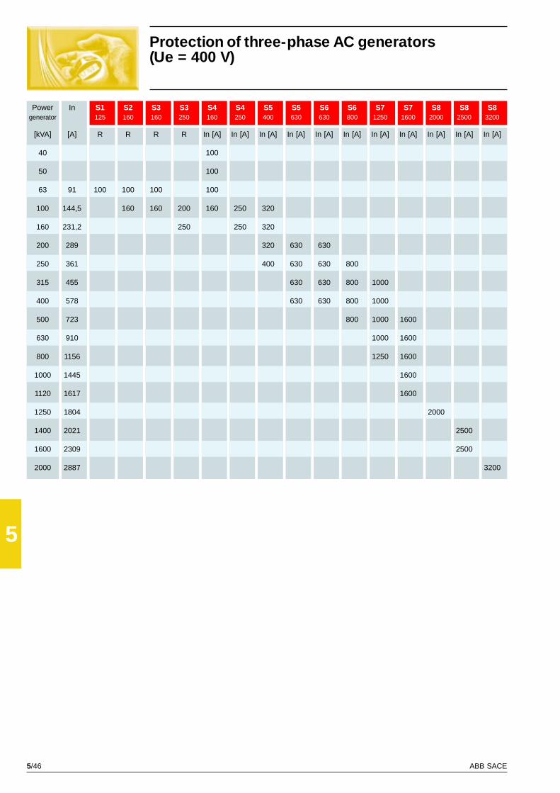
5/46 ABB SACE
5
In S1 S2 S3 S3 S4 S4 S5 S5 S6 S6 S7 S7 S8 S8 S8125 160 160 250 160 250 400 630 630 800 1250 1600 2000 2500 3200
[kVA] [A] R R R R In [A] In [A] In [A] In [A] In [A] In [A] In [A] In [A] In [A] In [A] In [A]
40 100
50 100
63 91 100 100 100 100
100 144,5 160 160 200 160 250 320
160 231,2 250 250 320
200 289 320 630 630
250 361 400 630 630 800
315 455 630 630 800 1000
400 578 630 630 800 1000
500 723 800 1000 1600
630 910 1000 1600
800 1156 1250 1600
1000 1445 1600
1120 1617 1600
1250 1804 2000
1400 2021 2500
1600 2309 2500
2000 2887 3200
Protection of three-phase AC generators(Ue = 400 V)
Powergenerator
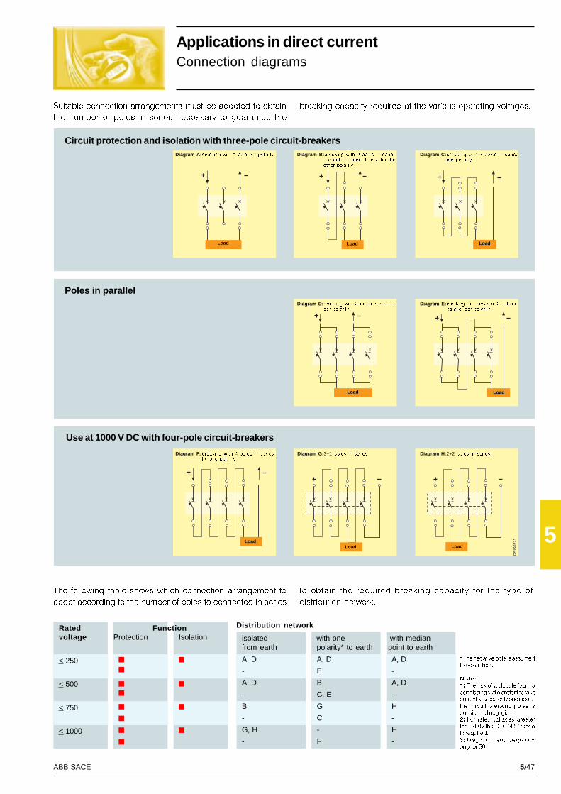
5/47ABB SACE
5G
SIS
0271
< 250
< 500
< 750
< 1000
A, D A, D A, D
- E -
A, D B A, D
- C, E -
B G H
- C -
G, H - H
- F -
Suitable connection arrangements must be adopted to obtain
the number of poles in series necessary to guarantee the
Applications in direct currentConnection diagrams
breaking capacity required at the various operating voltages.
Circuit protection and isolation with three-pole circuit-breakers
Poles in parallel
Use at 1000 V DC with four-pole circuit-breakers
The following table shows which connection arrangement to
adopt according to the number of poles to connected in series
to obtain the required breaking capacity for the type of
distribution network.
* The negative pole is assumed
to be earthed.
Notes
1) The risk of a double fault to
earth being sufficient for the fault
current to affect only one side of
the circuit breaking poles is
considered negligible.
2) For rated voltages greater
than 750V the 1000 VDC range
is required.
3) Diagram D and diagram E
only for S6.
LoadLoadLoad
Diagram F: breaking with 4 poles in seriesfor one polarity
Diagram G: 3+1 poles in series Diagram H: 2+2 poles in series
Diagram A: breaking with 1 pole per polarity Diagram B: breaking with 2 poles in seriesper polarity and 1 pole for theother polarity
Diagram C: breaking with 3 poles in seriesper polarity
Diagram D: breaking with 2 poles in parallelper polarity
Diagram E: breaking with series of 2 poles inparallel per polarity
Load LoadLoad
Load Load
Ratedvoltage
FunctionProtection Isolation
Distribution network
isolated with one with medianfrom earth polarity* to earth point to earth
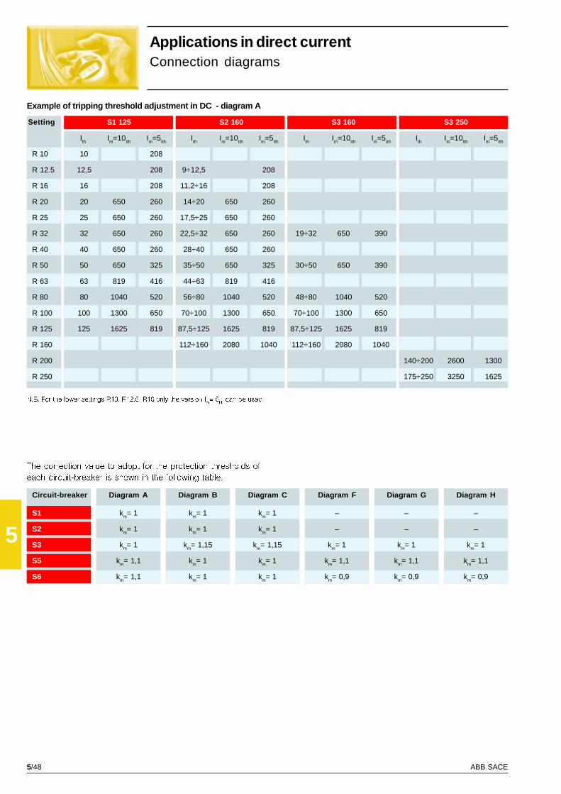
5/48 ABB SACE
5
S1 125 S2 160 S3 160 S3 250
Ith Im=10Ith Im=5Ith Ith Im=10Ith Im=5Ith Ith Im=10Ith Im=5Ith Ith Im=10Ith Im=5Ith
R 10 10 208
R 12.5 12,5 208 9÷12,5 208
R 16 16 208 11,2÷16 208
R 20 20 650 260 14÷20 650 260
R 25 25 650 260 17,5÷25 650 260
R 32 32 650 260 22,5÷32 650 260 19÷32 650 390
R 40 40 650 260 28÷40 650 260
R 50 50 650 325 35÷50 650 325 30÷50 650 390
R 63 63 819 416 44÷63 819 416
R 80 80 1040 520 56÷80 1040 520 48÷80 1040 520
R 100 100 1300 650 70÷100 1300 650 70÷100 1300 650
R 125 125 1625 819 87,5÷125 1625 819 87,5÷125 1625 819
R 160 112÷160 2080 1040 112÷160 2080 1040
R 200 140÷200 2600 1300
R 250 175÷250 3250 1625
km= 1
km= 1
km= 1,15
km= 1
km= 1
–
–
km= 1
km= 1,1
km= 0,9
–
–
km= 1
km= 1,1
km= 0,9
km= 1
km= 1
km= 1,15
km= 1
km= 1
–
–
km= 1
km= 1,1
km= 0,9
km= 1
km= 1
km= 1
km= 1,1
km= 1,1
S1
S2
S3
S5
S6
Applications in direct currentConnection diagrams
The correction value to adopt for the protection thresholds of
each circuit-breaker is shown in the following table.
N.B. For the lower settings R10, R12.5, R16 only the version Im= 5
Ith can be used
Setting
Diagram A Diagram C Diagram F Diagram G Diagram HDiagram BCircuit-breaker
Example of tripping threshold adjustment in DC - diagram A

5/49ABB SACE
5
Im
km x I
n
set =
5000
1,1 x 630set = » 7
S5 400 S5 630 S6 630 S6 800
Ith=0,7÷1xIn Im=5÷10xIn Ith=0,7÷1xIn Im=5÷10xIn Ith=0,7÷1xIn Im=5÷10xIn Ith=0,7÷1xIn Im= 5÷10xIn
R 320 225÷320 1760÷3520
R 400 280÷400 2200÷4400
R 500 350÷500 2750÷5500
R 630 440÷630 3065÷6930
R 800 560÷800 4400÷8800
Using these the correction factors means that the tripping cur-
rent values will be higher for the same tripping threshold, or,
vice versa, that having identified the tripping value one needs
to set the tripping threshold following the reclassified scale
range.
Example� Operating current: Ib = 600 A
� Magnetic protection required: Im = 5000 A
� Magnetic protection required
to set:
therefore in this specific case, having chosen circuit-breaker
S6 R630 (ln = 630 A), the magnetic threshold setting value will
be:
Setting

5/50 ABB SACE
5
S270 S280/20 S280/20 S290 S500 S1B S2B S1N S2N S3N S4N S5N S6N S2S S6S S7S
In [A] < 125 160 125 160 250 250 630 800 160 800 1600
Icu [kA] 15 20 25 15 50 16 16 25 35 35 35 35 35 50 50 50
10 S240 S240 S240 S240 S240
15S240 S240S250 S250
16 S250 S250 S250 S250S240 S250 S250 S270 S1B S1B S250 S1B
20 S250 S2B S2B S2BS270
S240 S270 S270 S270 S280/20 S270
25S250 S280/20 S280/20 S1BS270 S280/25 S2B
S1B
30S240 S280/20 S280/25 S280/25 S280/20
S280/25 S1B S1N S1N S1N S280/25
35S1B S1NS1N S2BS2B
S250 S1N S3N
40S4NS5NS6N
S270 S1B S2NS280/20 S1N S3N
50 S280/25 S2B S4NS1B S2N S5NS1N
65
85
100
130
150170
200
Backup protection(backup table with Ue = 400 V~)
The table below shows the backup protection available, with
the related breaking capacities for the rated voltage
Ue=400V~, between ABB moulded-case and air low voltage
circuit-breakers (SACE Isomax S, SACE Limitor LNA and SACE
Emax) and pro M system modular circuit-breakers.
CIRCUIT-BREAKER UPSTREAM
CIRCUIT-BREAKER DOWNSTREAM
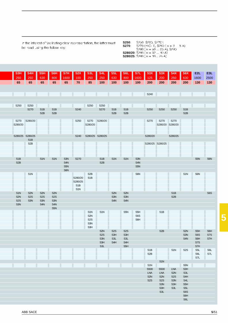
5/51ABB SACE
5
S3H S4H S5H S6H S7H S2X S3L S4L S5L S6L S7L S3X S3X S4X S6X E2L E3L
250 250 630 800 1600 100 250 250 630 800 1600 125 200 250 630 1600 2500
65 65 65 65 65 70 85 100 100 100 100 200 200 200 200 130 130
S240
S250 S250 S250 S250S270 S1B S1B S240 S270 S1B S1B S250 S250 S250 S1B
S2B S2B S2B S2B S2B
S270 S280/20 S250 S270 S280/20 S270 S270 S270S280/20 S280/20 S280/20 S280/20
S280/25 S280/25 S240 S280/25 S280/25 S280/20 S280/25S1BS2B S280/25 S280/25
S1B S1N S1N S3N S270 S1B S1N S1N S3N S5N S6NS2B S4N S2B S4N
S5N S5NS6N
S1N S2B S6N S1N S6NS280/20 S1BS280/25
S1BS1N
S1N S2N S2N S2N S2N S2N S1B S6SS2N S2S S2S S2S S3N S3N S2BS2S S3N S3N S3N S4N S4NS3N S4N S4N
S5NS1N S1N S5N S5H S1BS2N S6SS2S S6HS3NS3H
S2N S2S S2S S2B S2N S5H S6HS2S S3H S3H S3N S6S S7SS3N S3L S3L S4N S6H S7HS3H S4H S4H S7SS3L S5H S7H
S1B S1N S2S S5L S6LS2B S6L S7L
S7LS1N
S1N S5NS500 S500 LNA S3HLNA LNA S2N S3LS2N S2N S2S S4HS2S S2S S3N S4L
S3N S3H S5HS3H S3L S5LS3L S6S
S6HS6L
In the interest of facilitating clear representation, the latter must
be read using the follow key:
S250: S250, S260, S270KS270: S270 (B-C-D), S280 (In = 3 ... 8 A),
S280 (In = 50 ... 63 A), S290S280/20: S280 (In = 32 ... 40 A)S280/25: S280 (In = 10... 25 A)

5/52 ABB SACE
5

6/1ABB SACE
6
Index
Overall dimensions
SACE Isomax S1-S2
Fixed circuit-breaker ............................................................................................................ 6/2
Plug-in circuit-breaker .......................................................................................................... 6/3
Circuit-breaker with SACE RC210-RC211-RC212 residual current releases ..................... 6/4
Accessories .......................................................................................................................... 6/5
SACE Isomax S3-S4-S5-S3X-S4X
Fixed circuit-breaker ............................................................................................................ 6/7
Mounting parts for fixed circuit-breaker ............................................................................... 6/9
Plug-in circuit-breaker - withdrawable circuit-breaker ......................................................... 6/10
Mounting parts for plug-in circuit-breaker - withdrawable circuit-breaker ........................... 6/11
SACE S3 circuit-breaker with SACE RC211/3 - RC212/3 residual current releases ......... 6/12
Accessories .......................................................................................................................... 6/14
SACE Isomax S6-S6X
Fixed circuit-breaker ............................................................................................................ 6/18
Mounting parts for fixed circuit-breaker ............................................................................... 6/20
Withdrawable circuit-breaker ............................................................................................... 6/22
Mounting parts for withdrawable circuit-breaker ................................................................. 6/23
Accessories .......................................................................................................................... 6/24
SACE Isomax S7
Fixed circuit-breaker ............................................................................................................ 6/28
Mounting parts for fixed circuit-breaker ............................................................................... 6/29
Withdrawable circuit-breaker ............................................................................................... 6/30
Mounting parts for withdrawable circuit-breaker ................................................................. 6/31
Accessories .......................................................................................................................... 6/32
SACE Isomax S8
Fixed circuit-breaker ............................................................................................................ 6/36
Mounting parts for fixed circuit-breaker ............................................................................... 6/37
Distances to be respected .............................................................................................. 6/38
Minimum distance between centres ............................................................................. 6/39
Circuit diagramsIndex ................................................................................................................................... 6/41
Overall dimensions andcircuit diagrams

6/2 ABB SACE
6
GS
IS00
01
X
Y
X
Y
X X X120
E EE
A
B
48
C
(4 POL)
(3 POL)
3
71 1.5÷2
G
45 45
3
=
=
=
=
240
71(*)
X
(**)
X
E
E
EM8 ø 11
75
42
102
39
A
Y
62
100
E
M4/ø4.5
= =
(3-4 POL)
DF
(3 POL)
(4 POL)
1
75
2
4
4
4
Y
E
4 POL
3 POL
= =
M4/ø4.5
102 100
62
ø18
63
E E
L
M
96
H
3
3
I
24.5
H
I
X X
15
27.5
5
23.5
17.5ø 8.5
(*)
E
Y
XX
ø4
N
P
O
53
Y
64
Q
R 1.5
1
X
S1
S2
...
...
...
...
...
...
...
...
...
Q
43
49
P
42
48
M
62
60
L
29
27
I
10.5 x 11
12.5 x 12.5
H
25.5
27.5
G
91
93
F
116
133
E
25
30
D
91
103
C
39
45
B
103
120
A
78
90
N3 POL 4 POL
83.5 108.5
95.5 125.5
O3 POL 4 POL
86 111
98 128
Overall dimensionsSACE S1-S2
Fixed circuit-breaker
Mounting onsheet metal
Key
Flange for compartment door
Bracket for fitting circuit-breakeron DIN channel (to order)
Separator plate
Sealable screws
Terminals
Front for Cu cables or flatbars(with separator plates between thephases)
Threaded rear(**) low terminal covers included in supply (protection class IP20)
Template for drilling sheet metal support(minimum thickness of sheet metal: 3 mm)
For front terminals For threaded rear terminals
Template for drilling compartment door and fitting flange(thickness of sheet metal: 1.5 - 2 mm)
Mounting onDIN EN 50022 channel
Terminal covers(to order when not included in supply) (*) 75 with sealable screws
Front for Cu cables orflat bars(with high or low terminalcovers)
Extended front for S2(*) high terminal covers included insupply
1
2
3
4
Low High
View A

6/3ABB SACE
6
GS
IS00
02
I
O
o
off
SAC
YB
X
70
163
A
E E E
(4 POL)
= =(3 POL)
C
34
2
1
³ 2.510
45
50
124
123(*)
75
G52
42
X
A2.5
10
X
39
102
40
76
M8
Y
(4 POL)(3 POL)
60MAX102144
M4 ø4.5
(4 POL)
(3 POL)
5.535
M
E
R R
8463
EM
1
96
DF (4 POL)
(3 POL)
=
=
1.5÷2 mm
E
E
E
26
65.5
Y
X
ø4
N
P
O
53
Y
64
Q
R 1.5
X
X
Y
(4 POL)(3 POL)
5
60MAX
84
144
M4 ø4.5
LM
RR
(4 POL)(3 POL)
5.535
LM
YY
R 13
I
2.5
X
H
X
6
5
6
S1
S2
...
...
...
...
...
...
R
12.5
15
Q
43
49
P
42
48
O3 POL 4 POL
86 111
98 128
M
50
60
L
75
90
I
10.5 x 11
12.5 x 12.5
H
28
28
G
91
93
F
116
133
E
25
30
D
91
103
C
39
45
B
103
120
A
78
90
N3 POL 4 POL
83.5 108.5
95.5 125.5
Fixed parts mounted on sheet metal or channel(terminal covers for mobile part with IP20 always included in supply)
(*)127 mm with sealable screws
TerminalsFront Threaded rear
View A
Drilling template for support (5) or channel (6)(minimum thickness of sheet metal: 2.5 mm)
For front terminals For threaded rear terminals
Template for drillingcompartment door and fittingflange(thickness of sheet metal: 1.5 - 2 mm)
Plug-in circuit-breaker
Key
Flange for compartment door
Sealable screws
Fixed part
Moving part complete with terminalcovers
1
2
3
4
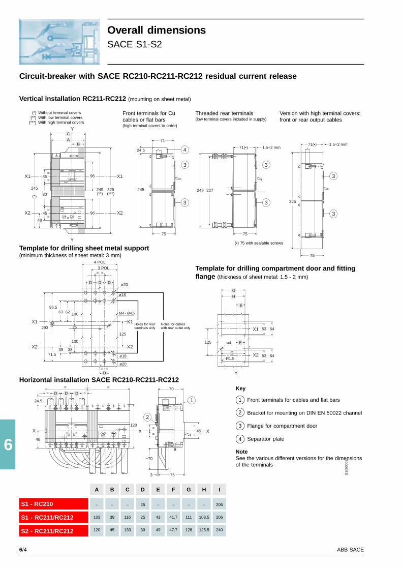
6/4 ABB SACE
6
293X1
X2
D D
= =
ø20
ø18
M4 - Ø4,5
ø18
ø20
D
96.5
38
63 62 100
X1
X2100
25
383971.5
D
3 POL4 POL
I
O
o
off
SAC
SAC
245
(*)
X1
X2 45
48=
=
45=
=
249(**)
325(***)
Y
AB
245
71
75
3
3
3
3
71(•) 1.5÷2 mm
227249
75
3
3
75
325
71(•) 1.5÷2 mm
125
80
C
96
96
X1
X2
Y
424.5
G
H
E
X1
X2
125
Y
53 64
53 64
F
G
ø4
R1.5
X
48
1
2
70
X=
=45
=
=
753
~70
X
==== D D D
120
I
24.5
GS
IS00
03
= =
S1 - RC210
S1 - RC211/RC212
S2 - RC211/RC212
A
–
103
120
B
–
39
45
C
–
116
133
D
25
25
30
E
–
43
49
F
–
41.7
47.7
G
–
111
128
H
–
108.5
125.5
I
206
206
240
Overall dimensionsSACE S1-S2
Circuit-breaker with SACE RC210-RC211-RC212 residual current release
Key
Front terminals for cables and flat bars
Bracket for mounting on DIN EN 50022 channel
Flange for compartment door
Separator plate
Front terminals for Cucables or flat bars(high terminal covers to order)
Template for drilling sheet metal support(minimum thickness of sheet metal: 3 mm)
Template for drilling compartment door and fittingflange (thickness of sheet metal: 1.5 - 2 mm)
1
2
3
4
Vertical installation RC211-RC212 (mounting on sheet metal)
(*) Without terminal covers(**) With low terminal covers
(***) With high terminal covers
Threaded rear terminals(low terminal covers included in supply)
Version with high terminal covers:front or rear output cables
Horizontal installation SACE RC210-RC211-RC212
(•) 75 with sealable screws
Holes for rearterminals only
Holes for cableswith rear outlet only
NoteSee the various different versions for the dimensionsof the terminals
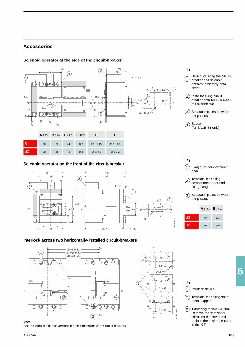
6/5ABB SACE
6
Y
Y
Y
X X
SACE S
SACE S
92
120
124
124
24.5
=
=
48
24.5
45
50
3
6.7
52
53
6280 0.15
= =
==
78
150G
SIS
0004
91
70.24
1
X X
X
Y
X
X
+–100
64
0.15
0.15
+–
+–
Y66
83.5
85
R1.5
0.15
0.15
+–
+–
3
3
2
1
2
X X XX
Y
=
=
=50
4596
A
B
BA
C
D
E F
=140.5 23
147
1.5-2
X
115 (S1÷S1)
X
Y Y1
117.5 (S1÷S2)120 (S2÷S2)
Y Y1 Y
SACE
GS
IS00
05
X
62 903030
X100
4.5-M4
X90
3025
X
X90
3025
X
Y
Y
2
3
1
S2÷S2
S1÷S2
S1÷S1
S1
S2
E
25 ± 0.15
30 ± 0.1
A 3 POL
78
90
B 3 POL
162
168
C 4 POL
64
75
D 4 POL
187
198
F
38.5 ± 0.2
36 ± 0.2
S1
S2
A 3 POL
78
90
B 4 POL
103
120
Accessories
Solenoid operator at the side of the circuit-breaker
Key
Drilling for fixing the circuit-breaker and solenoidoperator assembly ontosheet
Plate for fixing circuit-breaker onto DIN EN 50022rail (a richiesta)
Separator plates betweenthe phases
Spacer(for SACE S1 only)
1
2
3
4
Solenoid operator on the front of the circuit-breakerKey
Flange for compartmentdoor
Template for drillingcompartment door andfitting flange
Separator plates betweenthe phases
1
2
3
Interlock across two horizontally-installed circuit-breakers
Key
Interlock device
Template for drilling sheetmetal support
Tightening torque 1,1 NmRemove the screws forstirruping the cover andreplace them with the onesin the KIT.
1
2
3
NoteSee the various different versions for the dimensions of the circuit-breakers
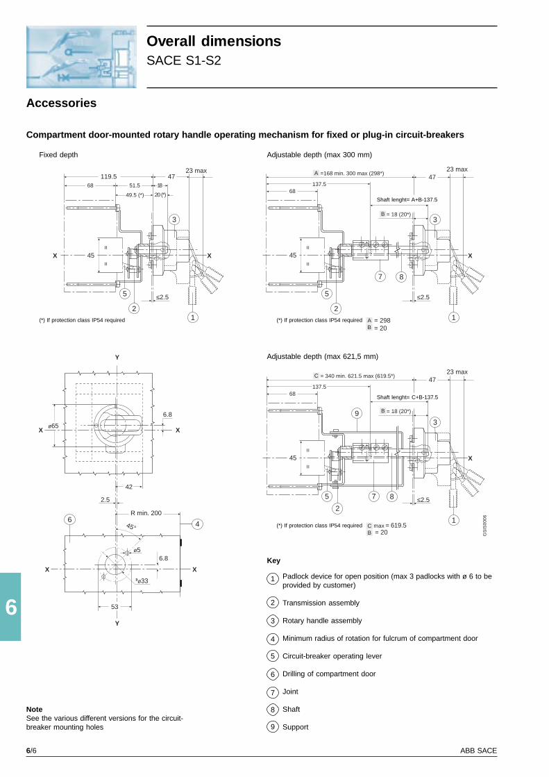
6/6 ABB SACE
6
X X
X X
45°
R min. 200
Y
Y
42
2.5
6.8ø5
³ø33
53
46
6.8
ø65
≤2.5
X
4723 max
=168 min. 300 max (298*)
45
==
7
3
8
12
5
68
≤2.5
X
4723 max
119.5
45
==
3
12
5
68 51.5
X
49.5 (*)
18
20 (*)
GS
IS00
06
A
B
B = 298 = 20A
= 18 (20*)
137.5
≤2.5
X
4723 max
= 340 min. 621.5 max (619.5*)
45
==
7
3
8
1
5
68
C
B = 18 (20*)
137.5
= 619.5 = 20 max
2
9
BC
Overall dimensionsSACE S1-S2
Accessories
Compartment door-mounted rotary handle operating mechanism for fixed or plug-in circuit-breakers
Fixed depth
(*) If protection class IP54 required
Adjustable depth (max 300 mm)
Shaft lenght= A+B-137.5
(*) If protection class IP54 required
Adjustable depth (max 621,5 mm)
Shaft lenght= C+B-137.5
(*) If protection class IP54 required
NoteSee the various different versions for the circuit-breaker mounting holes
Key
Padlock device for open position (max 3 padlocks with ø 6 to beprovided by customer)
Transmission assembly
Rotary handle assembly
Minimum radius of rotation for fulcrum of compartment door
Circuit-breaker operating lever
Drilling of compartment door
Joint
Shaft
Support
1
2
3
4
5
6
7
8
9

6/7ABB SACE
6
I
O
o
off
X
Y
A
F
V
Z
C
D
105
E E
Y
161
E
= =
G
H
H253
135101.5
105
=
=
103.5107 2
5
108 4.5
10.25
4522.5
2.546
X
10 (S3-S3X)15 (S4-S5)
3 (*)
I
M8 (S3/S3X-S4/S4X)M10 (S5)
5
20
X
I
L 31.2 ø21(**)
53.8 (S5 400)
ø15.5 (S5 400)31.8
X
117
1
1
2 3
X1
4
(4 POL)
(3 POL)
B
4
I
O
o
off
I
O
o
off
57 (S5 630)
ø20 (S5 630)
GS
IS00
07
A
105
105
140
140
100
105
S3
S4
S5 400
S5 630
S3X
S4X
Z
17.5
17.5
19.5
19.5
17.5
17.5
V
24
24
31
31
24
24
L
18x18
18x18
24x24
–
18x18
18x18
I
73.75
107.25
107.25
107.25
158.75
196.75
H
10
11
12
12
10
11
G
143
218
218
218
228
307.5
F
Ø 8
Ø 8
Ø 10
Ø 10
Ø 8
Ø 8
E
35
35
43.75
43.75
35
35
D
87.25
125.25
125.25
125.25
175.25
210.25
C
170
254
254
254
255
359
B
140
140
183.75
183.75
140
140
Fixed circuit-breaker
Mounting on sheet metal Mounting on DIN EN50023 channel
Terminal covers(to order when not included in supply)
Low High
(*) 3 mm = minimum admissiblethickness for S5 400
1 x 240 mm2 (S5 400) 2 x 120 mm2
For SACE S5 400 - S5 630 only
(**) high terminal coversincluded in the supply
Overall dimensionsSACE S3-S4-S5-S3X-S4X
Key
Flange for compartment door
Bracket for mounting on DIN EN 50023channel
45 mm front flange
Tightening torque 2 Nm
1
2
3
4
Terminals
Front for flat bars Front for cables
For SACE S3 - S4S5 400 - S3X - S4X only
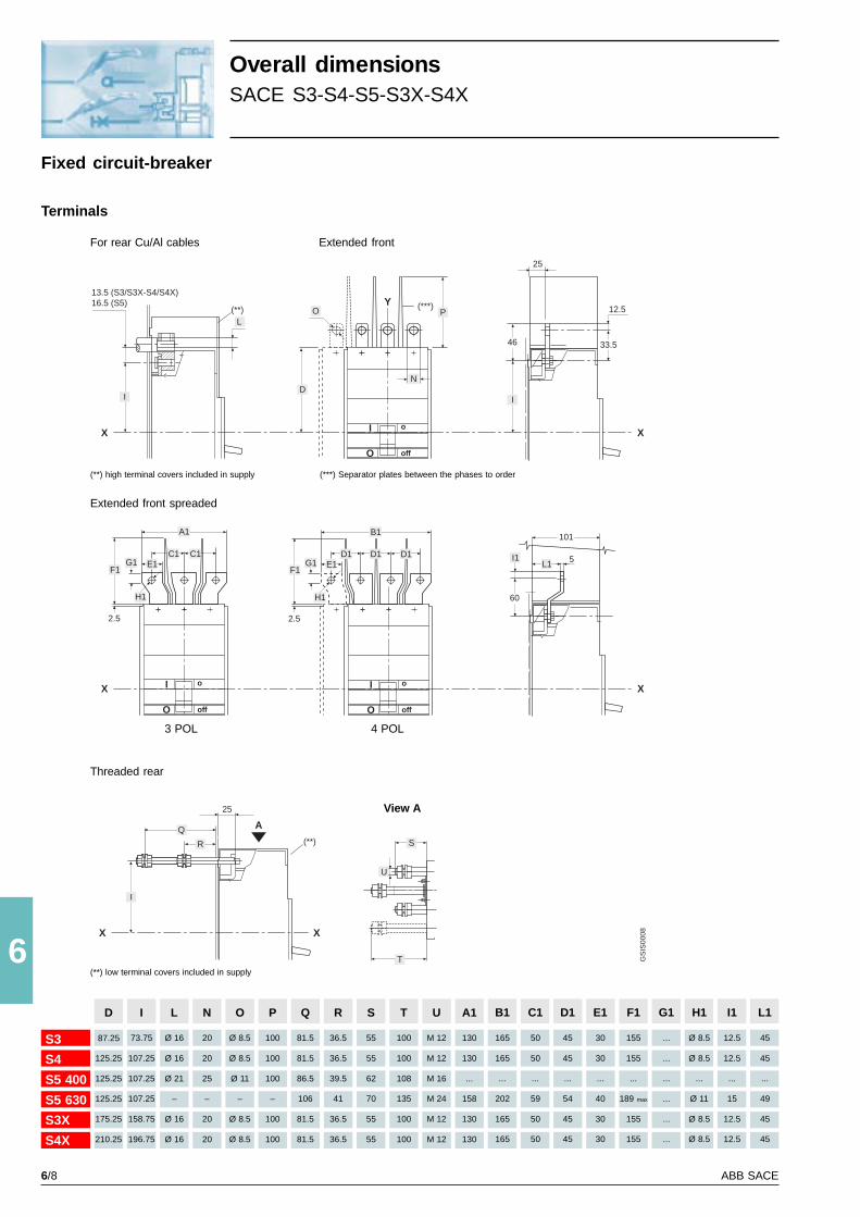
6/8 ABB SACE
6
A
X
(**)
X
S
T
25
R
Q
I
U
GS
IS00
08
X
I
L(**) (***)
D
P
N
I
33.546
6
25
X
O
13.5 (S3/S3X-S4/S4X)16.5 (S5)
I
O
o
off
F1
I
O
o
off
E1D1 D1 D1
B1
G1
2.5
H1
F1
I
O
o
off
E1C1 C1
A1
G1
2.5
H1
X X
Y
60
101
I1 5L1
12.5
D
87.25
125.25
125.25
125.25
175.25
210.25
S3
S4
S5 400
S5 630
S3X
S4X
S
55
55
62
70
55
55
R
36.5
36.5
39.5
41
36.5
36.5
Q
81.5
81.5
86.5
106
81.5
81.5
P
100
100
100
–
100
100
O
Ø 8.5
Ø 8.5
Ø 11
–
Ø 8.5
Ø 8.5
N
20
20
25
–
20
20
L
Ø 16
Ø 16
Ø 21
–
Ø 16
Ø 16
I
73.75
107.25
107.25
107.25
158.75
196.75
U
M 12
M 12
M 16
M 24
M 12
M 12
T
100
100
108
135
100
100
A1
130
130
...
158
130
130
L1
45
45
...
49
45
45
I1
12.5
12.5
...
15
12.5
12.5
H1
Ø 8.5
Ø 8.5
...
Ø 11
Ø 8.5
Ø 8.5
G1
...
...
...
...
...
...
F1
155
155
...
189 max
155
155
E1
30
30
...
40
30
30
D1
45
45
...
54
45
45
C1
50
50
...
59
50
50
B1
165
165
...
202
165
165
Overall dimensionsSACE S3-S4-S5-S3X-S4X
For rear Cu/Al cables
(**) high terminal covers included in supply
Extended front
(***) Separator plates between the phases to order
Threaded rear
View A
(**) low terminal covers included in supply
Terminals
Extended front spreaded
3 POL 4 POL
Fixed circuit-breaker
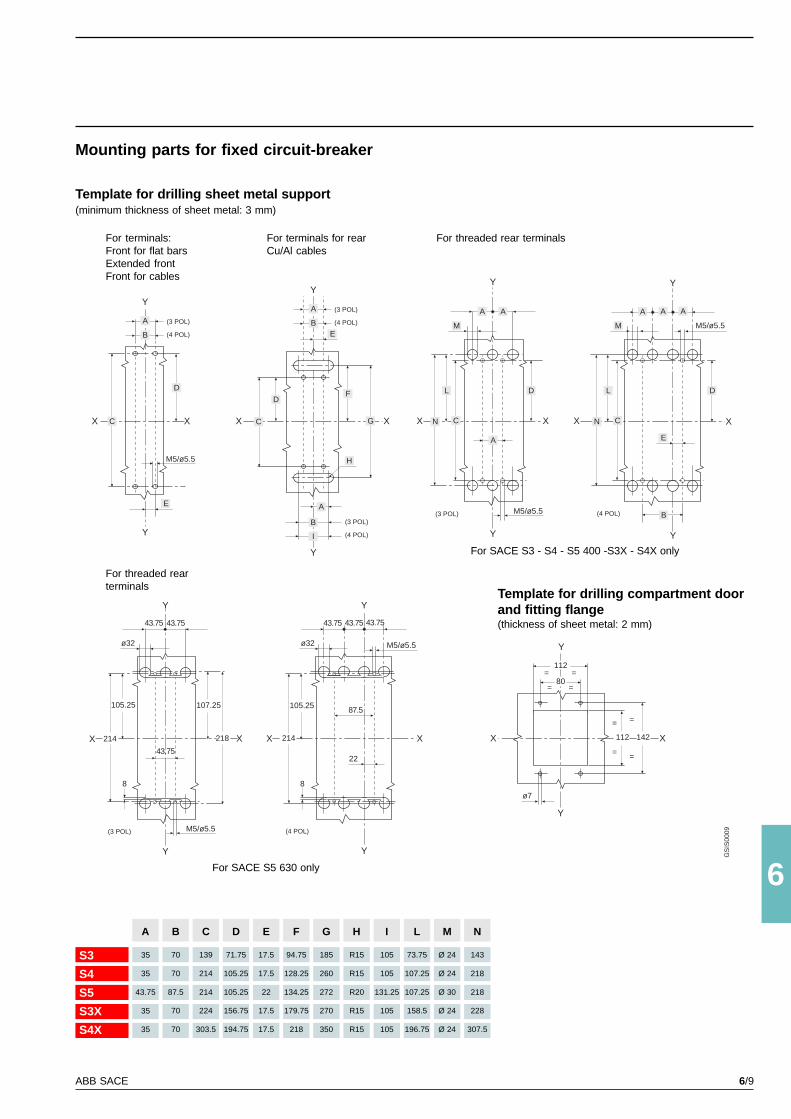
6/9ABB SACE
6
Y
Y
X X
D
A
B
C
E
M5/ø5.5
X C
Y
A
BE
X
F
G
Y
A
I
B
H
Y
Y
M5/ø5.5
A
CX
L
N
M
A A
X
M5/ø5.5
A A A
Y
C
L
NX
E
B
M
Y
Y
XX
80= =
112= =
112
=
=
142
=
=
ø7
DD
GS
IS00
09
(3 POL)
(4 POL)
(3 POL)
(4 POL)
(3 POL)
(4 POL)
(3 POL) (4 POL)
Y
Y
M5/ø5.5
X X
M5/ø5.5
Y
Y
X X
(3 POL) (4 POL)
43.75 43.75
ø32
107.25
218
105.25
43.75
214
43.75 43.75 43.75
8
ø32
105.25
214
22
87.5
8
X
Y
D
S3
S4
S5
S3X
S4X
A
35
35
43.75
35
35
M
Ø 24
Ø 24
Ø 30
Ø 24
Ø 24
L
73.75
107.25
107.25
158.5
196.75
I
105
105
131.25
105
105
H
R15
R15
R20
R15
R15
G
185
260
272
270
350
F
94.75
128.25
134.25
179.75
218
E
17.5
17.5
22
17.5
17.5
D
71.75
105.25
105.25
156.75
194.75
C
139
214
214
224
303.5
B
70
70
87.5
70
70
N
143
218
218
228
307.5
Mounting parts for fixed circuit-breaker
Template for drilling sheet metal support(minimum thickness of sheet metal: 3 mm)
For terminals:Front for flat barsExtended frontFront for cables
For terminals for rearCu/Al cables
Template for drilling compartment doorand fitting flange(thickness of sheet metal: 2 mm)
For threaded rear terminals
For SACE S5 630 only
For SACE S3 - S4 - S5 400 -S3X - S4X only
For threaded rearterminals
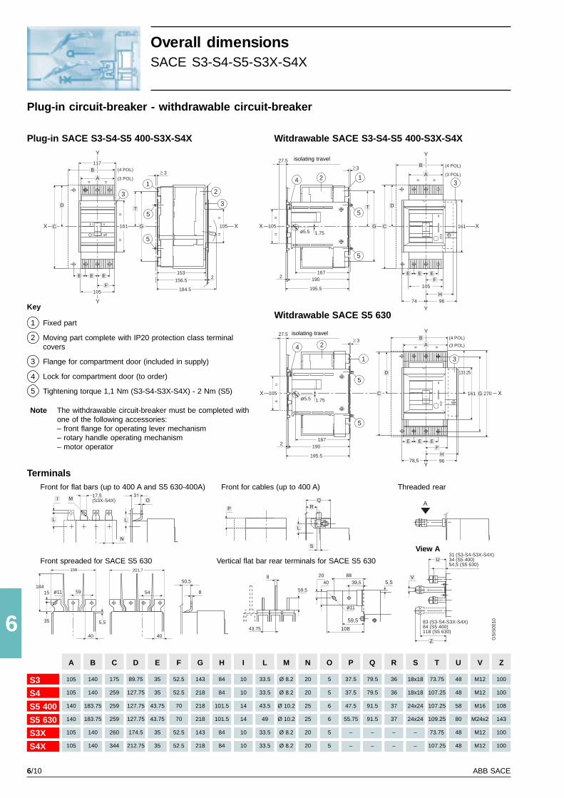
6/10 ABB SACE
6
AQ
R
S
P
GS
IS00
10
Y
Y
X
= =
161
=
=
117
3
105
=
=
X
1532
156.5
184.5
15 ø11
35
40
59
ø11
(4 POL)
(3 POL)
(4 POL)
(3 POL)
(4 POL)
(3 POL)
40
54
161 X
= =
Y
Y
1.75ø5.5
9674
161 X
= =
Y
Y
1
1
105
=
=
X
27.5
167190
2
195.5
3
1.75ø5.5
9678,5
133.25
270
N
I
L
M
5
1
105
1
5
5
5
5
59.5
8
43.75
31 (S3-S4-S3X-S4X)34 (S5 400)54,5 (S5 630)
V
U
Z
59,5
10883 (S3-S4-S3X-S4X)84 (S5 400)118 (S5 630)
17,5(S3X-S4X)
L
L
5,5
158
184
201,7
5,5
3
3
I
O
o
off
B
D
E EE
F
C
3 2
3
A
B
A
E E EF
H
D
105
=
=
X
27.5
167190
2
195.5
24 3
C
BA
G
E E EF
H
D
1
24
C
5
G
T
G
T
105
A
105
105
140
140
105
105
S3
S4
S5 400
S5 630
S3X
S4X
Q
79.5
79.5
91.5
91.5
–
–
P
37.5
37.5
47.5
55.75
–
–
O
5
5
6
6
5
5
N
20
20
25
25
20
20
M
Ø 8.2
Ø 8.2
Ø 10.2
Ø 10.2
Ø 8.2
Ø 8.2
L
33.5
33.5
43.5
49
33.5
33.5
I
10
10
14
14
10
10
H
84
84
101.5
101.5
84
84
G
143
218
218
218
143
218
F
52.5
52.5
70
70
52.5
52.5
E
35
35
43.75
43.75
35
35
D
89.75
127.75
127.75
127.75
174.5
212.75
C
175
259
259
259
260
344
B
140
140
183.75
183.75
140
140
V
M12
M12
M16
M24x2
M12
M12
U
48
48
58
80
48
48
T
73.75
107.25
107.25
109.25
73.75
107.25
S
18x18
18x18
24x24
24x24
–
–
R
36
36
37
37
–
–
Z
100
100
108
143
100
100
Overall dimensionsSACE S3-S4-S5-S3X-S4X
Plug-in circuit-breaker - withdrawable circuit-breaker
Plug-in SACE S3-S4-S5 400-S3X-S4X Witdrawable SACE S3-S4-S5 400-S3X-S4X
isolating travel
Key
Fixed part
Moving part complete with IP20 protection class terminalcovers
Flange for compartment door (included in supply)
Lock for compartment door (to order)
Tightening torque 1,1 Nm (S3-S4-S3X-S4X) - 2 Nm (S5)
1
2
3
4
Witdrawable SACE S5 630
isolating travel
TerminalsFront for flat bars (up to 400 A and S5 630-400A) Threaded rearFront for cables (up to 400 A)
Front spreaded for SACE S5 630 Vertical flat bar rear terminals for SACE S5 630
5
Note The withdrawable circuit-breaker must be completed withone of the following accessories:– front flange for operating lever mechanism– rotary handle operating mechanism– motor operator
View A
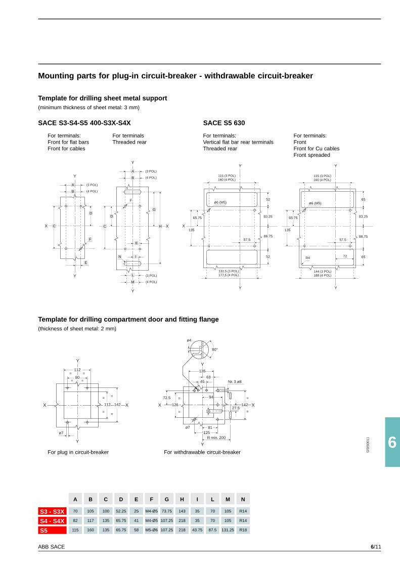
6/11ABB SACE
6
Y
Y
X
D
A
B
C
E
F
Y
Y
XX
80= =
112= =
112
=
=
142
=
=
ø7
X
80°
ø4
Y
Y
X
135
4563
81125
126
=
=
72.5
Nr. 3 ø8
142
=
=
R min. 200
27.5
94
16
GS
IS00
11
Y
Y
X
D
I
E
G
HC
F
A
B
L
M
N
Y
Y
X
ø6 (M5)
Y
Y
R4
135
65.75
57.5
52
86.75
83.25
52
57.5
ø6 (M5)
135
65.75
65
86.75
83.25
65
(3 POL)
(4 POL)
(3 POL)
(4 POL)
(3 POL)
(4 POL)
115 (3 POL)160 (4 POL)
132,5 (3 POL)177,5 (4 POL)
144 (3 POL)188 (4 POL)
115 (3 POL)160 (4 POL)
72
ø7
A
70
82
115
S3 - S3X
S4 - S4X
S5
M
105
105
131.25
L
70
70
87.5
I
35
35
43.75
H
143
218
218
G
73.75
107.25
107.25
F
M4-Ø5
M4-Ø5
M5-Ø6
E
25
41
58
D
52.25
65.75
65.75
C
100
135
135
B
105
117
160
N
R14
R14
R18
Mounting parts for plug-in circuit-breaker - withdrawable circuit-breaker
Template for drilling sheet metal support(minimum thickness of sheet metal: 3 mm)
For terminals:Front for flat barsFront for cables
For plug in circuit-breaker
For terminals:Vertical flat bar rear terminalsThreaded rear
Template for drilling compartment door and fitting flange(thickness of sheet metal: 2 mm)
For terminalsThreaded rear
SACE S3-S4-S5 400-S3X-S4X SACE S5 630
For terminals:FrontFront for Cu cablesFront spreaded
For withdrawable circuit-breaker
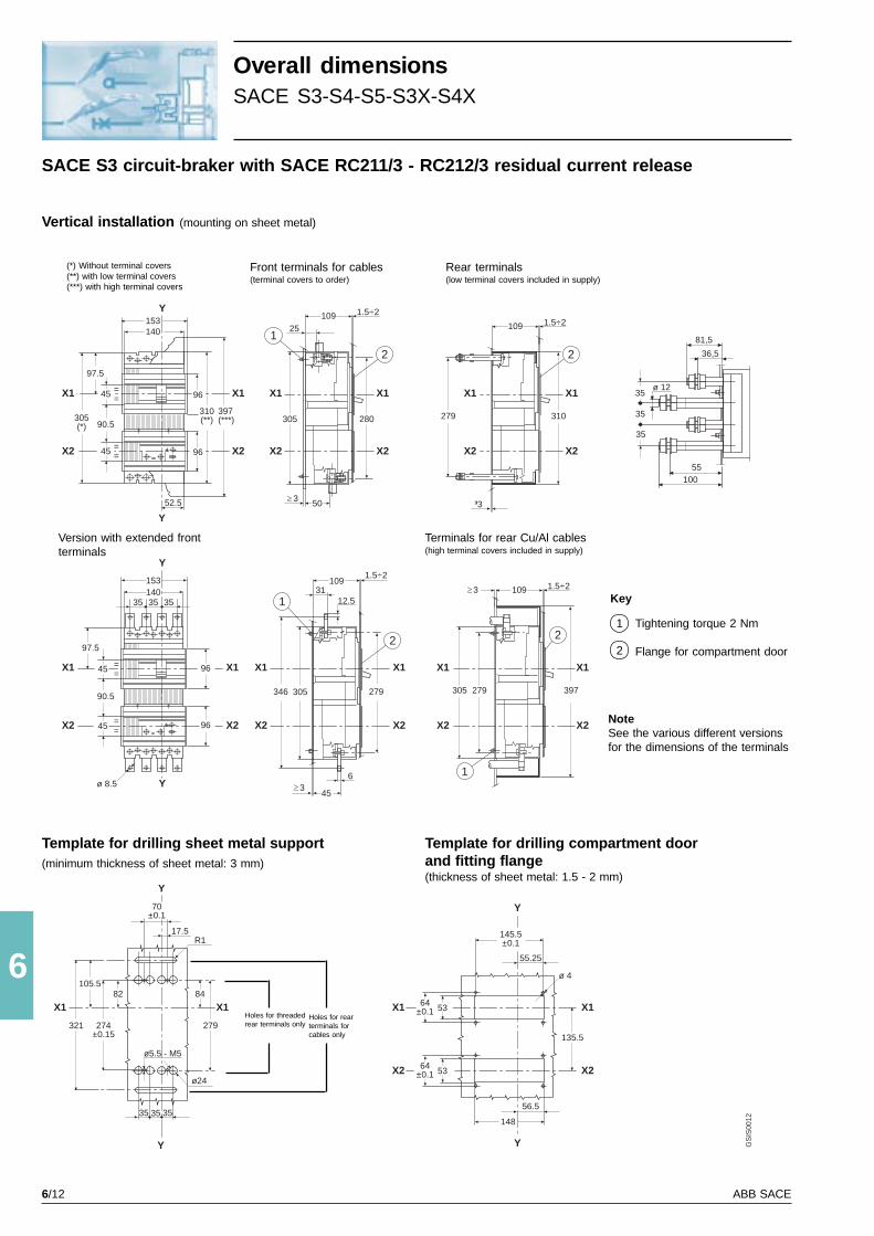
6/12 ABB SACE
6
Y
Y
X2
X1
397(***)
310(**)
45 ==
90.5
45 ==
97.5
305(*)
X2
X1
X2
X1
503
305 280
X2
X1
109 1.5÷2
25
279
X2
X1
X2
X1
310
³3
109 1.5÷2
109 1.5÷2
279305
X2
X1
X2
X1
1
2 2
2
Y
X2
X1 9645 ==
9645 ==
90.5
97.5
X2
X1
Y
35 35 35140153 109
1.5÷2
31
346 305
X2
X1
279
45
6
X2
X1
1
2
Y
35 35 35
ø5.5 - M5
ø24
X1
279
8482
274±0.15
321
X1
105.5
17.5
70±0.1
Y
R1
X1
X2
64±0.1 53
64±0.1 53
Y
Y
X1
X2
135.5
145.5±0.1
56.5
148
55.25
52.5
96
140153
3
397
12.5
96
GS
IS00
12
ø 4
36,5
81,5
55100
ø 1235
35
35
13ø 8.5
Overall dimensionsSACE S3-S4-S5-S3X-S4X
SACE S3 circuit-braker with SACE RC211/3 - RC212/3 residual current release
Vertical installation (mounting on sheet metal)
Front terminals for cables(terminal covers to order)
(*) Without terminal covers(**) with low terminal covers(***) with high terminal covers
Rear terminals(low terminal covers included in supply)
Terminals for rear Cu/Al cables(high terminal covers included in supply)
Version with extended frontterminals
Template for drilling sheet metal support(minimum thickness of sheet metal: 3 mm)
Template for drilling compartment doorand fitting flange(thickness of sheet metal: 1.5 - 2 mm)
Key
Tightening torque 2 Nm
Flange for compartment door
1
2
Holes for threadedrear terminals only
Holes for rearterminals forcables only
NoteSee the various different versionsfor the dimensions of the terminals
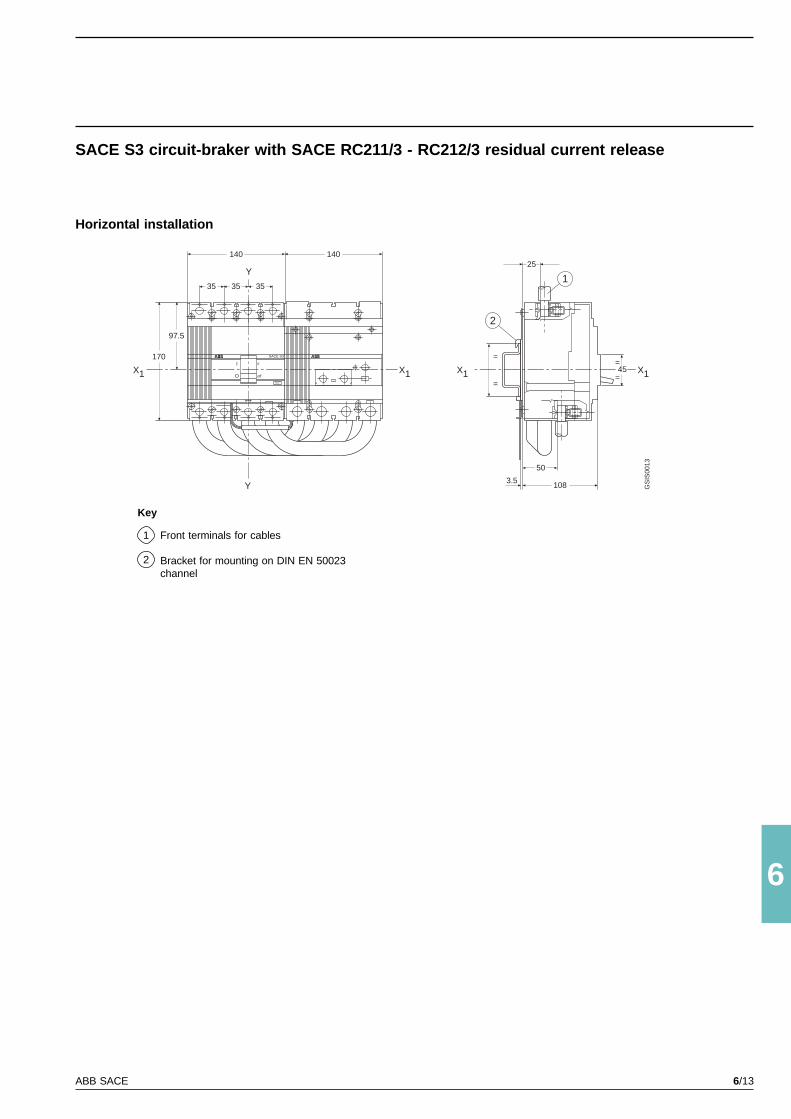
6/13ABB SACE
6
2
1
45=
=
50
1083.5
25140
SACE S3
I
O
o
off
TEST
X1
Y
Y
140
35 35 35
97.5
170 =
=
X1 X1 X1
GS
IS00
13
SACE S3 circuit-braker with SACE RC211/3 - RC212/3 residual current release
Horizontal installation
Key
Front terminals for cables
Bracket for mounting on DIN EN 50023channel
1
2
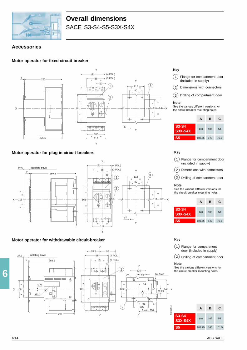
6/14 ABB SACE
6
Y
Y
X
80= =
112= =
112
=
=
142
=
=
ø7
3
Y
Y
X
80= =
112= =
112
=
=
142
=
=
ø7
X
27.5
2 269.5
=
105
=
=
Y
Y
C
B= =
A
117= =
31
2
Y
Y
X
135
63
81125
126
=
=
Nr. 3 ø8
142
=
=
R min. 200
27.25
94
16
=
161
X
=
105
=
1.75
ø5.5
27.5
2 269.5
167
Y
Y
=
161
=
C
B= =
A
96
2
1
2202
225.5
X
=
=
Y
Y
C
B= =
A
117= =
1
2
161
GS
IS00
14
(4 POL)
(3 POL)
105
(4 POL)
(3 POL)
78.5
(4 POL)
(3 POL)
ø7
ø7
A
140
183.75
S3-S4S3X-S4X
S5
C
58
75.5
B
105
140
A
140
183.75
S3-S4S3X-S4X
S5
C
58
75.5
B
105
140
A
140
183.75
S3-S4S3X-S4X
S5
C
58
101.5
B
105
140
Motor operator for fixed circuit-breaker
Accessories
Overall dimensionsSACE S3-S4-S5-S3X-S4X
Motor operator for plug in circuit-breakers
Motor operator for withdrawable circuit-breaker
isolating travel
isolating travel
Key
Flange for compartment door(included in supply)
Dimensions with connectors
Drilling of compartment door
1
2
3
NoteSee the various different versions forthe circuit-breaker mounting holes
Key
Flange for compartment door(included in supply)
Dimensions with connectors
Drilling of compartment door
1
2
3
NoteSee the various different versions forthe circuit-breaker mounting holes
Key
Flange for compartmentdoor (included in supply)
Drilling of compartment door
1
2
NoteSee the various different versions forthe circuit-breaker mounting holes
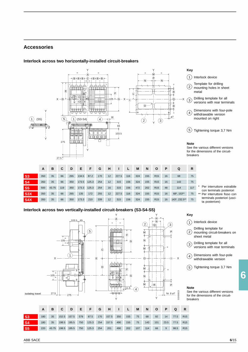
6/15ABB SACE
6
Y
B B B C B B B
A
X
E
D 105
F
G
Y
H
65
103.5
27.5
275
15 4
Y
Y
X X
M
NP
N
Q
RL
I
ø7
E
5
103.5 65
105=
=
1
Y
X X
105=
=
27.5275
D
C
F
G
F
G
11.5 4B
Y
Y
Y
2 3
I
HN
= =
= =
O
Nr. 8 ø7
=
=
1
Y
Y
(S5) (S3-S4)
BB
A
GS
IS00
15
= =
= =
= =
R
=
=
M
M
N
M
M
N
P
P
Q
O
R
2 3
A
180
180
220
S3
S4
S5
Q
77.5
77.5
98.5
P
14
23.5
9
O
92
101
66
N
68
143
114
M
75
75
107
L
155
155
202
I
350
490
490
H
157.5
157.5
201
G
170
254
254
F
87.5
125.3
125.3
E
578
750
750
D
157.5
195.5
195.5
C
152.5
198.5
198.5
B
35
35
43.75
R
R15
R15
R15
F
87.2
125.3
125.3
172
210
G
170
254
254
255
339
H
12
12
16
12
12
I
227.5
315
315
227.5
315
L
116
156
156
116
156
M
324
324
472
324
324
N
155
155
202
155
155
O
R15
R15
R15
R15
R15
P
16
16
48
16
16
Q
68
143
114
68*, 153**
143*, 232.5**
R
75
75
117
75
75
D
265
350
350
265
350
C
66
66
119
66
66
B
35
35
43.75
35
35
A
350
350
500
350
350
E
134.5
173.5
173.3
135
173.3
S3
S4
S5
S3X
S4X
Accessories
Interlock across two horizontally-installed circuit-breakers
Interlock across two vertically-installed circuit-breakers (S3-S4-S5)
isolating travel
Key
Interlock device
Template for drillingmounting holes in sheetmetal
Drilling template for allversions with rear terminals
Dimensions with four-polewithdrawable versionmounted on right
Tightening torque 3,7 Nm
1
2
3
NoteSee the various different versionsfor the dimensions of the circuit-breakers
4
5
Key
Interlock device
Drilling template formounting circuit-breakers onsheet metal
Drilling template for allversions with rear terminals
Dimensions with four-polewithdrawable version
Tightening torque 3,7 Nm
1
2
3
NoteSee the various different versionsfor the dimensions of the circuit-breakers
4
5
* Per interruttore estraibilecon terminals posteriori
** Per interruttore fisso conterminals posteriori (usci-ta posteriore)
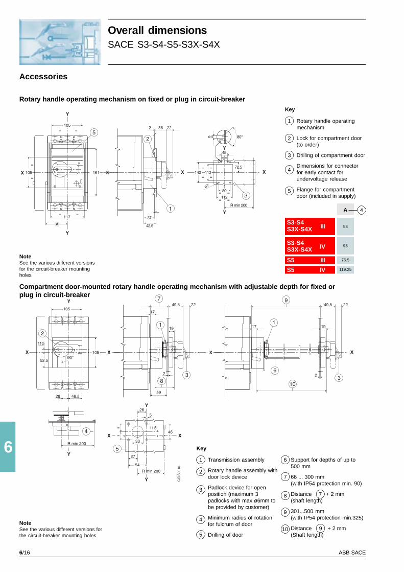
6/16 ABB SACE
6R min 200
142 112 XX
Y
X X
Y
X
X X
Y
Y
3
2
4
80
112
Y
= =
= =R min 200
ø7
Y
= =45
105
52.5
11.5
105
46.526
R min 200
265
27
54
33=
=46
11.5
=
=
=
=
72.5
90°
GS
IS00
16
5
A
Y
X X
Y
105
161105
117
= =
=
=
= =
59
5
80°ø42
1
7
1
83
1
9
6
103
S3-S4S3X-S4X III
S3-S4S3X-S4X IV
S5 III
S5 IV
4A
58
93
75.5
119.25
Rotary handle operating mechanism on fixed or plug in circuit-breaker
Accessories
Overall dimensionsSACE S3-S4-S5-S3X-S4X
Compartment door-mounted rotary handle operating mechanism with adjustable depth for fixed orplug in circuit-breaker
Key
Rotary handle operatingmechanism
Lock for compartment door(to order)
Drilling of compartment door
Dimensions for connectorfor early contact forundervoltage release
Flange for compartmentdoor (included in supply)
1
2
3
NoteSee the various different versionsfor the circuit-breaker mountingholes
NoteSee the various different versions forthe circuit-breaker mounting holes
4
5
Key
Transmission assembly
Rotary handle assembly withdoor lock device
Padlock device for openposition (maximum 3padlocks with max ø6mm tobe provided by customer)
Minimum radius of rotationfor fulcrum of door
Drilling of door
1
2
3
4
5
Support for depths of up to500 mm
66 ... 300 mm(with IP54 protection min. 90)
Distance + 2 mm(shaft length)
301...500 mm(with IP54 protection min.325)
Distance + 2 mm(Shaft length)
6
7
8
9
10
7
9
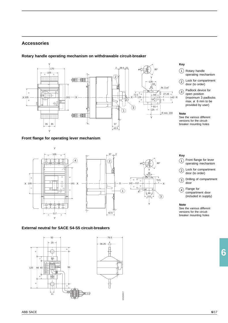
6/17ABB SACE
6
GS
IS00
17X3
14
56
In 5 6 Line
Load100
160200250
320400
50
25
11
9540120 66
=
=
=
=
=
=
76.5
36.254
Y
X
4
X
Y
X
Y
X
105
105 161
117= =
= =
=
=
=
=
42.5
37 2
2
1
380112
Y
= == =
ø7
142 112
=
=
=
=
= =45
72.5
105= =
Y
105
=
=X
170
X161
Y
3535 37
42.5
X
2 38.5 22
Y
X
Y
R min. 200
142=
=27.25
12581
94
16
80°ø4
135
4563
126=
=
72.5
Nr. 5 ø7
1
2
3
80°ø4
Accessories
Rotary handle operating mechanism on withdrawable circuit-breaker
Front flange for operating lever mechanism
External neutral for SACE S4-S5 circuit-breakers
Key
Rotary handleoperating mechanism
Lock for compartmentdoor (to order)
Padlock device foropen position(maximum 3 padlocksmax. ø 6 mm to beprovided by user)
1
2
3
NoteSee the various differentversions for the circuit-breaker mounting holes
KeyFront flange for leveroperating mechanism
Lock for compartmentdoor (to order)
Drilling of compartmentdoor
Flange forcompartment door(included in supply)
1
2
3
NoteSee the various differentversions for the circuit-breaker mounting holes
4
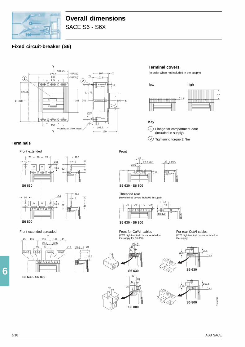
6/18 ABB SACE
6
Y
X
1401
X
Y
210279.5
104.75
125.25
268
152==
==
107
2
³3
12
105
=
=
159
914
2
40
70 70 70
ø11
48.5
S6 630
19.5ø21
12
S6 630S6 630
S6 800
111.75
241
16.5
161
101.5
103.5
S6 630 - S6 800
GS
IS00
18
S6 630 - S6 800
(4 POL)
(3 POL)
ø1450
53.5
S6 800
41.5
8 20
4767
41.5
5 15
4762
S6 800
16.7512
ø17.5
3247
ø21.5
42
59ø20
25
23ø6.5
22.5 ±0.1
40
5 min.
12
2.570 70 707344
M24x2
ø1390 49.5 8
45116116116
S6 630 - S6 800
2.5
47
23
22.5 22.5
Y45
116.5
20
Fixed circuit-breaker (S6)
Threaded rear(low terminal covers included in supply)
Terminal covers(to order when not included in the supply)
low high
Terminals
Front extended Front
Front extended spreaded For rear Cu/Al cables(IP20 high terminal covers included inthe supply)
Front for Cu/Al cables(IP20 high terminal covers included inthe supply for S6 800)
Key
Flange for compartment door(included in supply)
Tightening torque 2 Nm
1
2
Mounting on sheet metal
Overall dimensionsSACE S6 - S6X
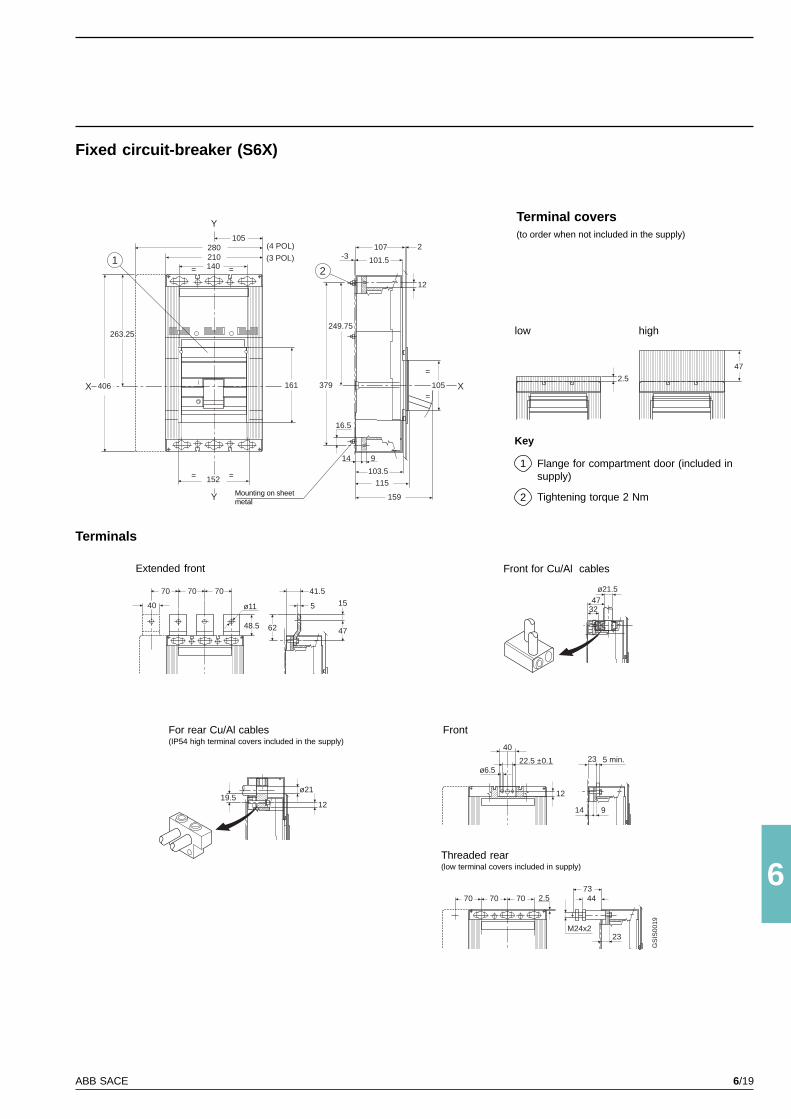
6/19ABB SACE
6
2.5
47
Y
X
140
X
Y
210280
105
263.25
406
152 ==
==
107
2
-3
12
105
=
=
159
914
2
249.75
379
16.5
161
101.5
103.5
(4 POL)
(3 POL)1
3247
ø21.5
23ø6.5
22.5 ±0.1
40
5 min.
12
2.570 70 707344
M24x2
19.5ø21
12
GS
IS00
19
115
40
70 70 70
ø11
41.5
5 15
476248.5
14 9
23
Fixed circuit-breaker (S6X)
Terminal covers(to order when not included in the supply)
low high
Key
Flange for compartment door (included insupply)
Tightening torque 2 Nm
1
2Mounting on sheetmetal
Terminals
Extended front Front for Cu/Al cables
For rear Cu/Al cables(IP54 high terminal covers included in the supply)
Front
Threaded rear(low terminal covers included in supply)
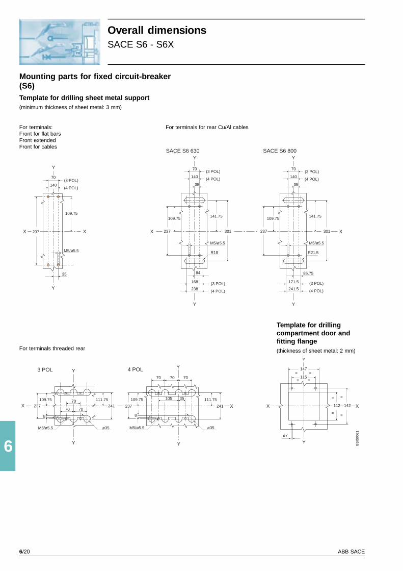
6/20 ABB SACE
6
Y
Y
X X
M5/ø5.5
35
237
109.75
70
140
Y
Y
70
140
35
237
141.75
301
84
168
238
R18
M5/ø5.5
Y
X
Y
70
140
35
237
141.75
301
85.75
171.5
241.5
R21.5
M5/ø5.5
Y
Y
X 237
109.75
8
M5/ø5.5 ø35
241
111.75
70 70
70
X
Y
Y
X237
109.75
8
M5/ø5.5 ø35
241
111.75105 35
70 70 70
109.75 109.75
SACE S6 630 SACE S6 800
GS
IS00
21
(3 POL)
(4 POL)
(3 POL)
(4 POL)
(3 POL)
(4 POL)
(3 POL)
(4 POL)
(3 POL)
(4 POL)
3 POL 4 POL
Y
Y
XX
115= =
147= =
112
=
=
142
=
=
ø7
Mounting parts for fixed circuit-breaker(S6)Template for drilling sheet metal support(minimum thickness of sheet metal: 3 mm)
Template for drillingcompartment door andfitting flange(thickness of sheet metal: 2 mm)For terminals threaded rear
For terminals for rear Cu/Al cablesFor terminals:Front for flat barsFront extendedFront for cables
Overall dimensionsSACE S6 - S6X

6/21ABB SACE
6
Y
Y
XX
115= =
147= =
112
=
=
142
=
=
ø7
Y
Y
X X
M5/ø5.5
35
375
247.75
70
140
Y
Y
70
140
35
375
279.75
439
84
168
238
R18
M5/ø5.5
Y
Y
X 375
247.75
8
M5/ø5.5 ø35
379
249.75
70 70
70
X
Y
247.75
(3 POL)
(4 POL)
(3 POL)
(4 POL)
(3 POL)
(4 POL)
3 POL
X
109.75
109.75
Y
X375
247.75
M5/ø5.5
379
249.75
105 35
70 70 70
4 POL
8
ø35
109.75
109.75
GS
IS00
20
Mounting parts for fixed circuit-breaker (S6X)
Template for drillingcompartment door andfitting flange(thickness of sheet metal: 2 mm)
Template for drilling sheet metal support(minimum thickness of sheet metal: 3 mm)
For terminals threaded rear
For terminals for rear Cu/Al cablesFor terminals:Front for flat barsFront extendedFront for cables

6/22 ABB SACE
6
GS
IS00
22
Y
27.5
Y
X
1
X
24
3
140 14.5
195.5
167
58
145208
89.5
295
133
152
A
70 70 70210
280
96 131
193.5
ø5.5=
=
1902
5
123.5 136.5
196
331
10
20
ø14 40
80.5
20
40
ø14
10
70 7070
(4 POL)
(3 POL)
3
158
X X XX
XXX X
A
273
411
S6
S6X
Withdrawable circuit-breaker
Terminals
Front for SACE S6 630, S6 800
Horizontal or vertical rear flat bar for SACE S6 630, S6 800
Key
Fixed part
Moving part
Flange for compartmentdoor (included in supply)
Lock for compartment door(to order)
Tightening torque 9 Nm
1
2
3
4
5
isolating travel
Overall dimensionsSACE S6 - S6X
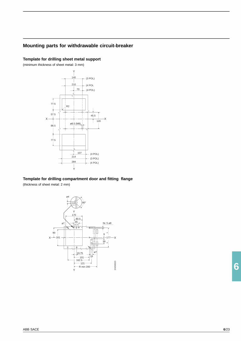
6/23ABB SACE
6
Y
Y
X X
140
210
70
120
214
284
107
45.557.5
77.5
86.5
77.5
ø8.5 (M8)
Y
Y
X X
4580.5
170
161
90
Nr. 5 ø8
177
39
9
=
=
R min 200
162.5101
19.75
= =
121
16
80°
ø4
GS
IS00
23
(3 POL)
(4 POL
(4 POL)
(4 POL)
(3 POL)
(4 POL)
R2
ø7
ø7
Mounting parts for withdrawable circuit-breaker
Template for drilling sheet metal support(minimum thickness of sheet metal: 3 mm)
Template for drilling compartment door and fitting flange(thickness of sheet metal: 2 mm)
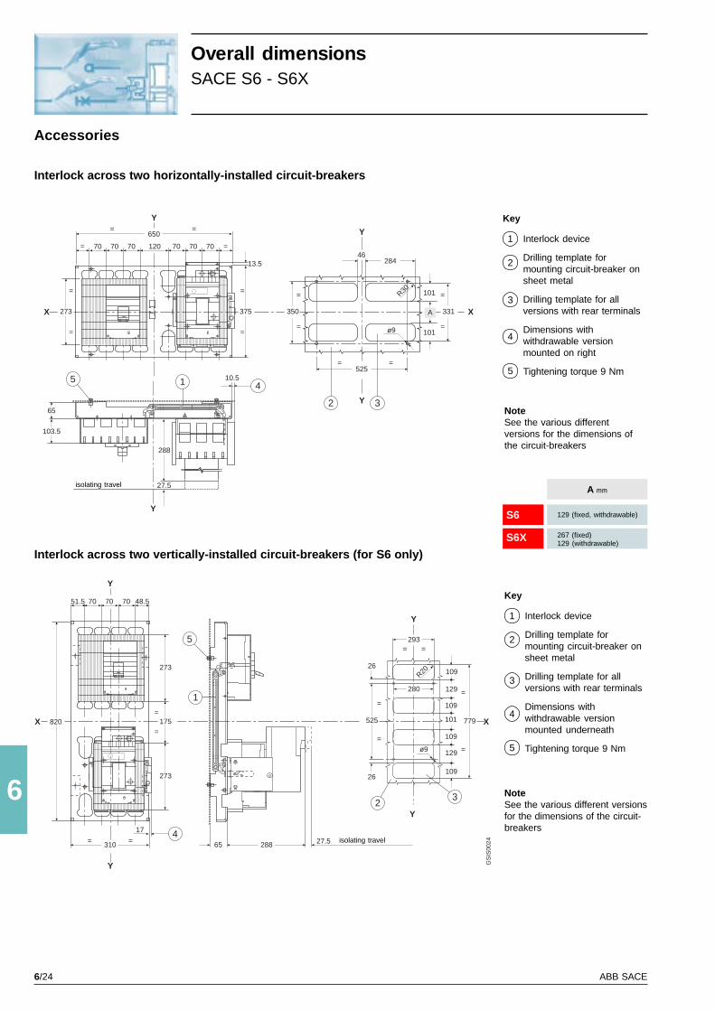
6/24 ABB SACE
6
Y
X
650
5
Y
X
Y
X X
Y
Y
Y
Y
Y
1 4
2 3
70 70 70 120 70 70 70 ==
375
13.5
=
=
10.5
288
27.5
350
=
=
273
=
=
525= =
ø9
R30
331
=
=
101
28446
70 70 7051.5 48.5
273
273
175
1
417
310 ==
=
=820
28865 27.5
5
23
293= =
525
=
=ø9
779
109
=
=
==
65
103.5
280
GS
IS00
24
101
A
26
26
109
129
101
109
109
129
R20
S6
S6X
Interlock across two horizontally-installed circuit-breakers
Overall dimensionsSACE S6 - S6X
Accessories
Interlock across two vertically-installed circuit-breakers (for S6 only)
isolating travel
isolating travel
NoteSee the various differentversions for the dimensions ofthe circuit-breakers
NoteSee the various different versionsfor the dimensions of the circuit-breakers
Key
Interlock device
Drilling template formounting circuit-breaker onsheet metal
Drilling template for allversions with rear terminals
Dimensions withwithdrawable versionmounted on right
Tightening torque 9 Nm
1
2
3
4
5
Key
Interlock device
Drilling template formounting circuit-breaker onsheet metal
Drilling template for allversions with rear terminals
Dimensions withwithdrawable versionmounted underneath
Tightening torque 9 Nm
1
2
3
4
5
A mm
129 (fixed, withdrawable)
267 (fixed)129 (withdrawable)
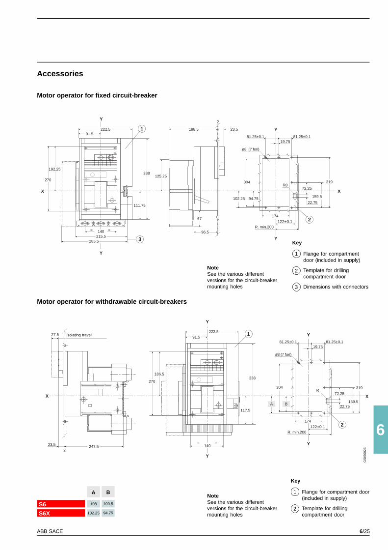
6/25ABB SACE
6
Y
X
222.5 1
Y
91.5
3
111.75
338
140= =
215.5285.5
192.25
270125.25
198.5
2
23.5
96.5
ø8 (7 fori)
Y
81.25±0.1 81.25±0.119.75
304
94.75102.25
174122±0.1
Y
R. min.200
319
X159.5
R8
2
22.75
72.25
ø8 (7 fori)
Y
81.25±0.1 81.25±0.119.75
304
174122±0.1
Y
R. min.200
319
X159.5
R
2
22.75
72.25
1
117.5
338
140= =
Y
X
Y
222.591.5
186.5
270
23.52
247.5
27.5
GS
IS00
25
67
A B
B
100.5
94.75
S6
S6X
A
108
102.25
Accessories
Motor operator for fixed circuit-breaker
Motor operator for withdrawable circuit-breakers
NoteSee the various differentversions for the circuit-breakermounting holes
Key
Flange for compartmentdoor (included in supply)
Template for drillingcompartment door
Dimensions with connectors
1
2
3
Key
Flange for compartment door(included in supply)
Template for drillingcompartment door
1
2
isolating travel
NoteSee the various differentversions for the circuit-breakermounting holes

6/26 ABB SACE
6
103.5
Y
140
196140
4
=
=
152
= =
=
=
104.75
3115
147
Y
= =
= =R min 200
ø7
177 147
=
=
=
=
Y45
90
80°ø42
1
2 44.5 22
42.5
4
R min 200
X
168
2
23
19
63 22103.5
Y
X 105
10541.5 31
36
28
2
7
3
1
6
Y
Y41.5
5
27
54
R min 200
33
4628
5
5
X
=
=
X
GS
IS00
26
37
2.75
Y
X104
8
M5/ø5.5 ø35
70 70
70
Y
X104
8
M5/ø5.5 ø35
244 (S6X)105 35
70 70 704 POL3 POL
Y
133 133
106 (S6)
379 (S6X)241 (S6)375 (S6X)
237 (S6)244 (S6X)106 (S6)
379 (S6X)241 (S6)375 (S6X)
237 (S6)
Y
X104
8
M5/ø5.5 ø35
70 70
70
Y
X104
8
M5/ø5.5 ø35
244 (S6X)105 35
70 70 704 POL3 POL
Y
133 133
106 (S6)
379 (S6X)241 (S6)375 (S6X)
237 (S6)244 (S6X)106 (S6)
379 (S6X)241 (S6)375 (S6X)
237 (S6)
Rotary handle operating mechanism on fixed circuit-breaker
Accessories
Compartment door-mounted rotary handle mechanism with adjustable depth for fixed circuit-breaker
Overall dimensionsSACE S6 - S6X
Key
Rotary handle operatingmechanism on circuit-breaker
Lock for compartment door(to order)
Drilling of compartment door
Flange for compartmentdoor (included in supply)
Tightening torque 2 Nm
1
2
3
4
5
NoteSee the various different versionsfor the circuit-breaker mountingholes
Key
Transmission assembly
Rotary handle assemblywith door lock device
Padlock device (maximum 3padlocks max ø 6 mm to beprovided by customer onlyfor circuit-breaker openposition)
Minimum radius of rotationfor fulcrum of door
Drilling template formounting circuit-breaker onsheet metal
72...506 mm (with IP54protection min. 96)
Distance -4 mm (shaft length)
1
2
3
4
5
NoteSee the various different versionsfor the circuit-breaker mountingholes
6
7 6
Drilling only required for version with rear terminals
Drilling only required for version with rear terminals
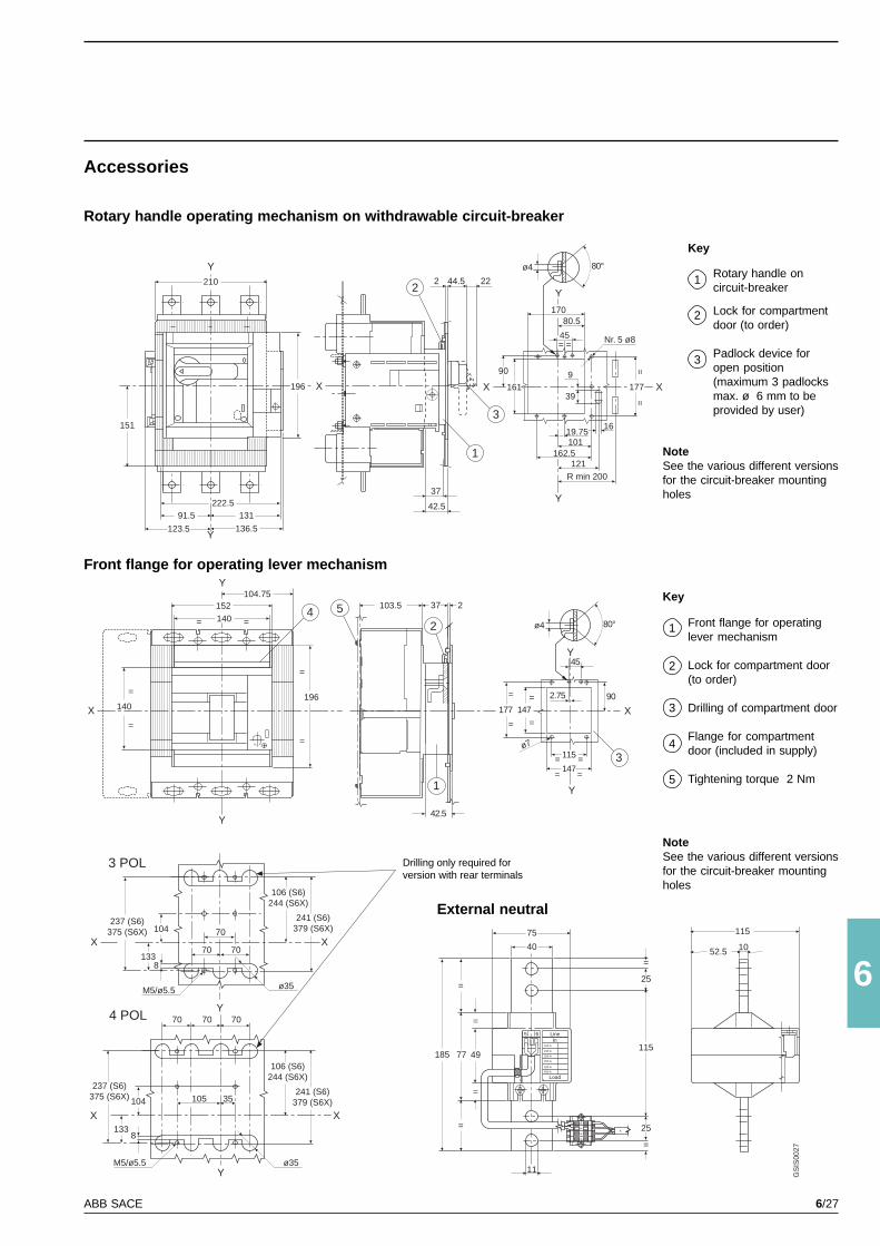
6/27ABB SACE
6
Y
X
140
196140
4
=
=
152
= =
=
=
104.75
3115
147
Y
= =
= =
ø7
177 147
=
=
=
=
45
90
2
1
42.5
5 103.5 37 2
2.75
X
115
52.5 10
In5 6 Line
Load
100 A
160 A
200 A
250 A
320 A
400 A
X
14
56
40
75
11
25
115
25
=
=
4977
=
=
=
=
185
Y
X X
Y
Y
161
90
45==
80.5170
19.75101
162.5121
R min 200
16
177
=
39
9
Nr. 5 ø8
Y
Y
X
151
210
91.5 131
123.5 136.5
196
222.5
2 44.5 22
1
2
3
37
42.5
Y
80°ø4
80°ø4
=
GS
IS00
27
X104
8
M5/ø5.5 ø35
70 70
70
Y
X104
8
M5/ø5.5 ø35
105 35
70 70 70
X
X
4 POL
3 POL
Y
133
133
375 (S6X)237 (S6)
244 (S6X)106 (S6)
379 (S6X)241 (S6)
244 (S6X)106 (S6)
379 (S6X)241 (S6)375 (S6X)
237 (S6)
Accessories
Rotary handle operating mechanism on withdrawable circuit-breaker
Front flange for operating lever mechanism
Key
Rotary handle oncircuit-breaker
Lock for compartmentdoor (to order)
Padlock device foropen position(maximum 3 padlocksmax. ø 6 mm to beprovided by user)
1
2
3
Key
Front flange for operatinglever mechanism
Lock for compartment door(to order)
Drilling of compartment door
Flange for compartmentdoor (included in supply)
Tightening torque 2 Nm
1
2
3
4
5
NoteSee the various different versionsfor the circuit-breaker mountingholes
External neutral
NoteSee the various different versionsfor the circuit-breaker mountingholes
Drilling only required forversion with rear terminals
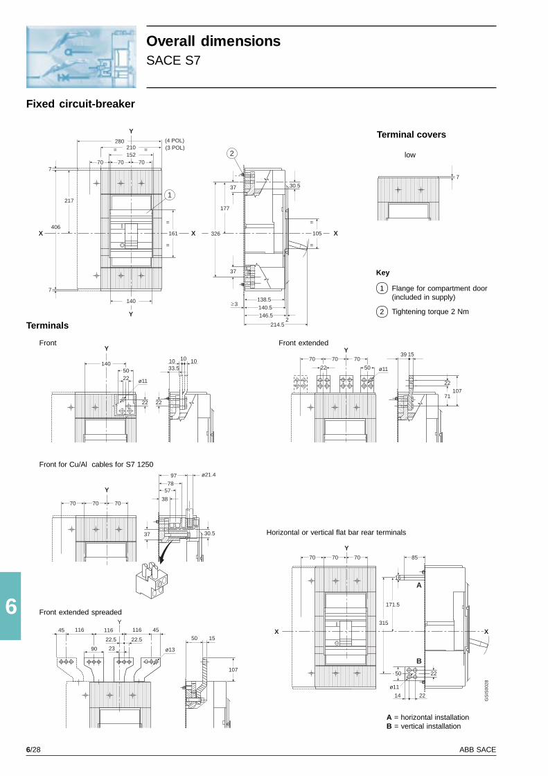
6/28 ABB SACE
6
Y
X
280
X
Y
210= =152
707070
406
7
7
217
161
=
=
140
1
2
326
37
177
37
105
=
=
X
30.5
146.52
140.5
138.53
7070
Y70 85
16
315
171.5
50 22
14 22
X X
A
B
GS
IS00
28
(4 POL)(3 POL)
7
214.5
Y
5022
140
22
10 1010
33.5
22
ø11
7070
Y70
22 50 ø11
71
22107
39 15
50 15
37
97 ø21.4
7857
38
30.5
7070
Y
70
ø1390
45116116116
23
22.5 22.5
Y45
ø11
107
A = horizontal installationB = vertical installation
Overall dimensionsSACE S7
Fixed circuit-breaker
Terminal covers
low
Terminals
Front extendedFront
Horizontal or vertical flat bar rear terminals
Front for Cu/Al cables for S7 1250
Key
Flange for compartment door(included in supply)
Tightening torque 2 Nm
1
2
Front extended spreaded

6/29ABB SACE
6
Y
Y
XX
115= =
147= =
112
=
=
142
=
=
ø7
Y
Y
X X
M5/ø5.5
35
378
203
70
140
378X
Y
Y
220
50 80
ø 3.6 H12
70= =
70 70R40
ø5.5 - M5
315
171.5203
378 X
Y
Y
290
50 80
ø 3.6 H12
140
70 70R40
ø5.5 - M5
315
171.5203
70
GS
IS00
29
(3 POL)
(4 POL)
35
Mounting parts for fixed circuit-breaker
Template for drilling compartment doorand fitting flange(thickness of sheet metal: 2 mm)
Template for drilling sheet metal support(Minimum thickness of sheet metal:3 mm)
For flat bar rear terminalsFor terminals:FrontFront extendedFront for Cu/Al cables
3 POL 4 POL

6/30 ABB SACE
6
Y3108
22 50
143.25
ø11
1422
70 70 70
16
331
16
Y
14
22
2250
70 70 70
ø11
X
XX
X
67
GS
IS00
30
27.5
X 140
247
196
218.5
ø5.5
160max 270
143.25
3
=
=
2
5
1
241.5
8.25
2
4
Y
Y
X406
211.25
140210
280
123.5 136.5
193.5
13196
3
(4 POL)(3 POL)
Overall dimensionsSACE S7
Withdrawable circuit-breaker
Terminals
Front
Horizontal or vertical flat bar rear terminals
Key
Fixed part
Moving part
Flange for compartmentdoor (included in supply)
Lock for compartment door(to order)
Tightening torque 9 Nm
1
2
3
4
5
isolating travel

6/31ABB SACE
6
Y
Y
X X
140
210
70
120
214
284
107
68.2592.5
120.5
76
120.5
ø8.5 (M8)
Y
Y
X X
4580.5
170
161
90
Nr. 5 ø8
177
39
9
=
=
R min 200
162.5
101
19.75 16
80°
ø4
= =
121
GS
IS00
31
(4 POL)
(3 POL)
(3 POL)
(4 POL)
ø7
ø7
Mounting parts for withdrawable circuit-breaker
Template for drilling sheet metal support or channel(Minimum thickness of sheet metal: 3 mm)
Template for drilling compartment door and fitting flange(thickness of sheet metal: 2 mm)
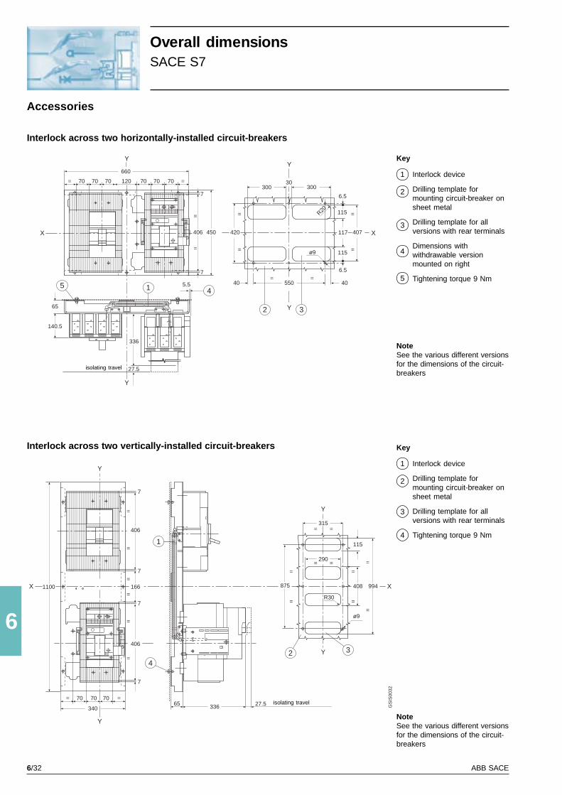
6/32 ABB SACE
6
1
140.5
65
Y
660
5 1 4
70 70 70 120 70 70 70 ==
406
7
=
=
5.5
336
27.5
Y
Y2 3
420
=
=
550= =
ø9
R20
407
=
=
115
30030
70 70 70= =
406
406
166
65340
=
=
=
1100
336 27.5
=
=
=
=4
7
7
7
7
315= =
875
=
=
ø9
994408
115
=
=
=
=
2 3
290= =
R30
X X
7
450
Y
Y
Y
X X
Y
Y
GS
IS00
32
300
117
6.5
115
6.5
4040
Overall dimensionsSACE S7
Accessories
Interlock across two horizontally-installed circuit-breakers
Interlock across two vertically-installed circuit-breakers
isolating travel
isolating travel
NoteSee the various different versionsfor the dimensions of the circuit-breakers
Key
Interlock device
Drilling template formounting circuit-breaker onsheet metal
Drilling template for allversions with rear terminals
Dimensions withwithdrawable versionmounted on right
Tightening torque 9 Nm
1
2
3
4
5
NoteSee the various different versionsfor the dimensions of the circuit-breakers
Key
Interlock device
Drilling template formounting circuit-breaker onsheet metal
Drilling template for allversions with rear terminals
Tightening torque 9 Nm
1
2
3
4
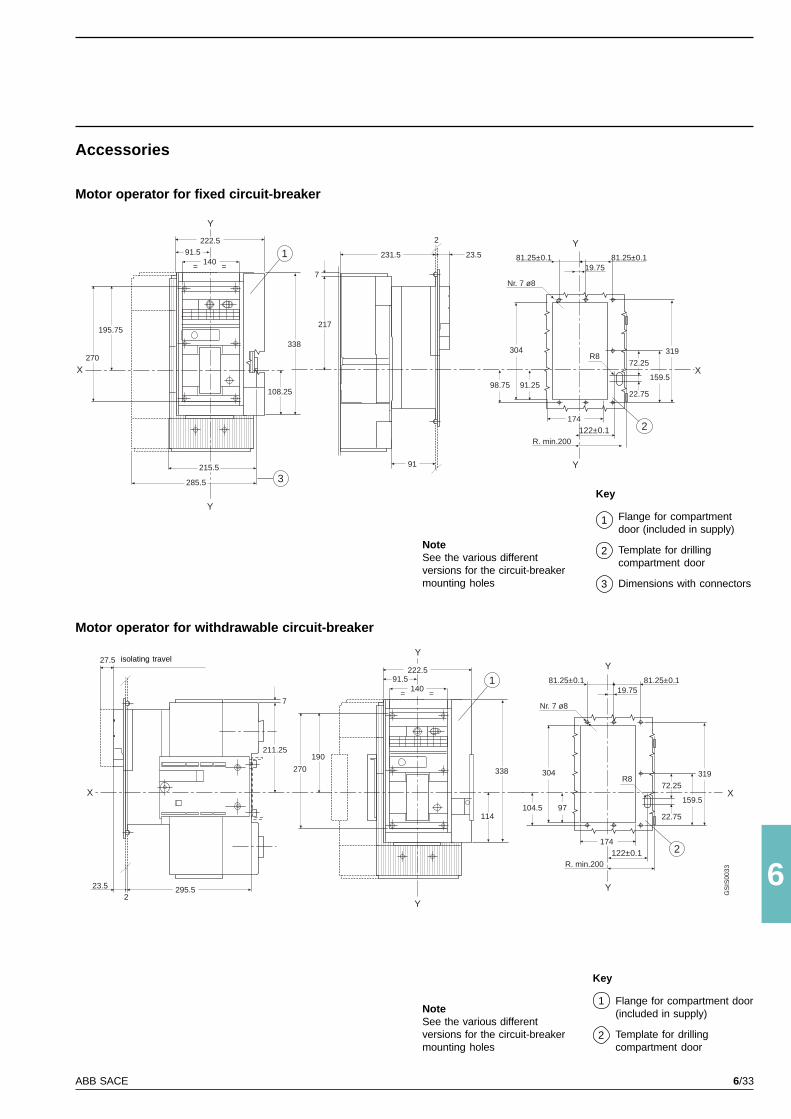
6/33ABB SACE
6
Y
222.51
Y
91.5
114
338
190
270
140= =
Nr. 7 ø8
Y
81.25±0.1 81.25±0.119.75
304
91.2598.75
174122±0.1
Y
R. min.200
319
X159.5
R8
2
22.75
72.25
X
211.25
23.52
295.5
27.5
Y
X
222.5
1
Y
91.5
3
108.25
338
215.5
285.5
195.75
270
140= =
217
231.5
2
23.5
91
7
7Nr. 7 ø8
Y
81.25±0.1 81.25±0.119.75
304
97104.5
174122±0.1
Y
R. min.200
319
X159.5
R8
2
22.75
72.25
GS
IS00
33
Accessories
Motor operator for fixed circuit-breaker
Motor operator for withdrawable circuit-breaker
NoteSee the various differentversions for the circuit-breakermounting holes
Key
Flange for compartmentdoor (included in supply)
Template for drillingcompartment door
Dimensions with connectors
1
2
3
Key
Flange for compartment door(included in supply)
Template for drillingcompartment door
1
2
isolating travel
NoteSee the various differentversions for the circuit-breakermounting holes
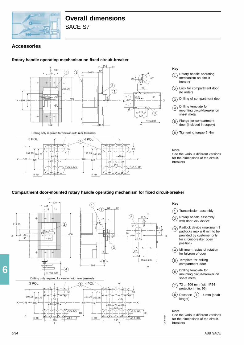
6/34 ABB SACE
6
3115
147
Y
= =
= =R min 200
ø7
177147
=
=
=
=
Y45
90
80°ø4
Y
X
105140
140
211.25
=
=
= =
406196
5
X
42.5
140.5 37
244.5
22
6
2
1
2.75
Y
X
105
41.5
105
211.25
406
19
31
105
4Y
Y41.5
5
27
54
R min 200
33
46
R min 200
32
8205
23
7 63 221
28X
=
=
5
50
378
197.25 165.75
315 70 70
70
ø5.5- M5
Y
X
50
378
197.25 165.75
31570 70
35
ø5.5- M5
Y
X70
140
4
50
378
197.25 165.75
315 70 70
70
ø5.5- M5
Y
X
50
378
197.25 165.75
31570 70
35
ø5.5- M5
Y
X70
140
6
152
R 40 R 40
28
36 90°
80
ø3.6 H12R 40220Y
ø3.6 H12290
Y
R 40
80
2
GS
IS00
34
3 POL 4 POL
3 POL 4 POL
Overall dimensionsSACE S7
Accessories
Rotary handle operating mechanism on fixed circuit-breaker
Compartment door-mounted rotary handle operating mechanism for fixed circuit-breaker
NoteSee the various different versionsfor the dimensions of the circuit-breakers
Key
Rotary handle operatingmechanism on circuit-breaker
Lock for compartment door(to order)
Drilling of compartment door
Drilling template formounting circuit-breaker onsheet metal
Flange for compartmentdoor (included in supply)
Tightening torque 2 Nm
1
2
3
4
5
Drilling only required for version with rear terminals
Drilling only required for version with rear terminals 6
Key
Transmission assembly
Rotary handle assemblywith door lock device
Padlock device (maximum 3padlocks max ø 6 mm to beprovided by customer onlyfor circuit-breaker openposition)
Minimum radius of rotationfor fulcrum of door
Template for drillingcompartment door
Drilling template formounting circuit-breaker onsheet metal
72 ... 506 mm (with IP54protection min. 96)
Distance - 4 mm (shaftlenght)
1
2
3
4
5
6
7
78
NoteSee the various different versionsfor the dimensions of the circuit-breakers

6/35ABB SACE
6
3115
147
Y
= =
= =
ø7
177 147
=
=
=
=
45
90
Y
X
105140
140
211.25
=
=
= =
406196
5
42.5
140.5 37
2
6
2
1
X
152
2.75
GS
IS00
35
115
52.5 10
In5 6 Line
Load
100 A
160 A
200 A
250 A
320 A
400 A
X
14
56
40
75
11
25
115
25
=
=
4977
=
=
=
=
185
50
378
197.25 165.75
315 70 70
70
ø5.5- M5
Y
X
4
R 40
Y
50
378
197.25 165.75
31570 70
35
ø5.5- M5
X70
140
R 40
Y
X
4
X X X
Y
Y
210==
196
=
=
211.25
406
222.591.5 131
136.5123.537
42,5
2 44.5 22
X
Y
161
90
45==
80.5170
19.75101
162.5121
R min 200
16
177
=
=39
9
Nr. 7 ø7
1
2
3
4 POL
3 POL
Y
80°ø4
Y
80°ø4
X
Accessories
Rotary handle operating mechanism on withdrawable circuit-breaker
Front flange for operating lever mechanism
Drilling only required forversion with rear terminals
External neutral
Key
Rotary handle operatingmechanism on circuit-breaker
Lock for compartment door(to order)
Padlock device for openposition (maximum 3padlocks max. ø 6 mm to beprovided by user)
1
2
3
NoteSee the various different versionsfor the circuit-breaker mountingholes
NoteSee the various different versionsfor the circuit-breaker mountingholes
Key
Front flange for leveroperating mechanism
Lock for compartment door(to order)
Drilling of compartment door
Drilling template formounting circuit-breaker onsheet metal
Flange for compartmentdoor (included in supply)
Tightening torque 2 Nm
1
2
3
4
5
6
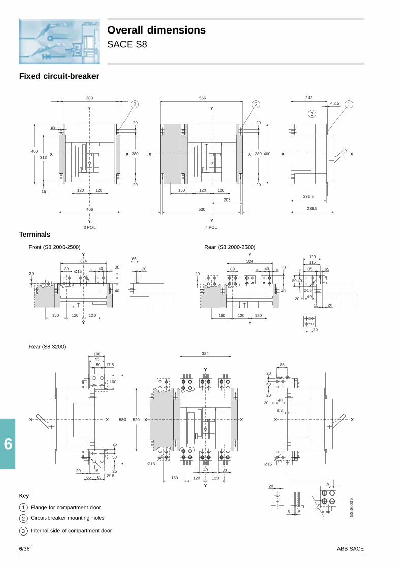
6/36 ABB SACE
6
65
65
15
Y Y
Y Y
324 324
120 120120 120
Ø15
Ø15
XX
2.5
3
242
286,5
236,5
=
X
Y
Y
X
324
X
Y
Y
X
380
120120150
203
530=
280
20
20
400
==
120120
406
2
280
20
20
313
15
400
ø9
80 8040 40
40
40
40 40
= == =20 20
20
20
20
20
8520 20
150 150
3 POL 4 POL
80
=
=
115120
2 1
3
520 X
Y
X X
Y
Y
556
120120150
80
20
5
40= =
Ø15
Ø18
Ø15
8550 17,5
10040
50
40
20
25
20
2520
20
XX X
95100
580
15
6565
5
GS
IS00
36
Overall dimensionsSACE S8
Fixed circuit-breaker
Terminals
Rear (S8 2000-2500)Front (S8 2000-2500)
Key
Flange for compartment door
Circuit-breaker mounting holes
Internal side of compartment door
1
2
Rear (S8 3200)
3
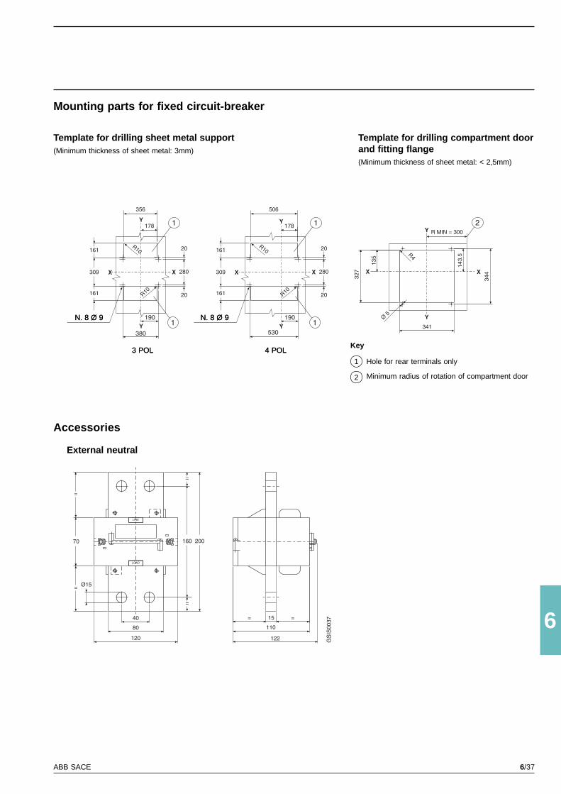
6/37ABB SACE
6
N. 8 Ø 9
3 POL 4 POL
N. 8 Ø 9
Mounting parts for fixed circuit-breaker
Template for drilling sheet metal support(Minimum thickness of sheet metal: 3mm)
N. 8 Ø 9
3 POL 4 POL
Template for drilling compartment doorand fitting flange(Minimum thickness of sheet metal: < 2,5mm)
Key
Hole for rear terminals only
Minimum radius of rotation of compartment door
1
2
Accessories
External neutral
N. 8 Ø 9
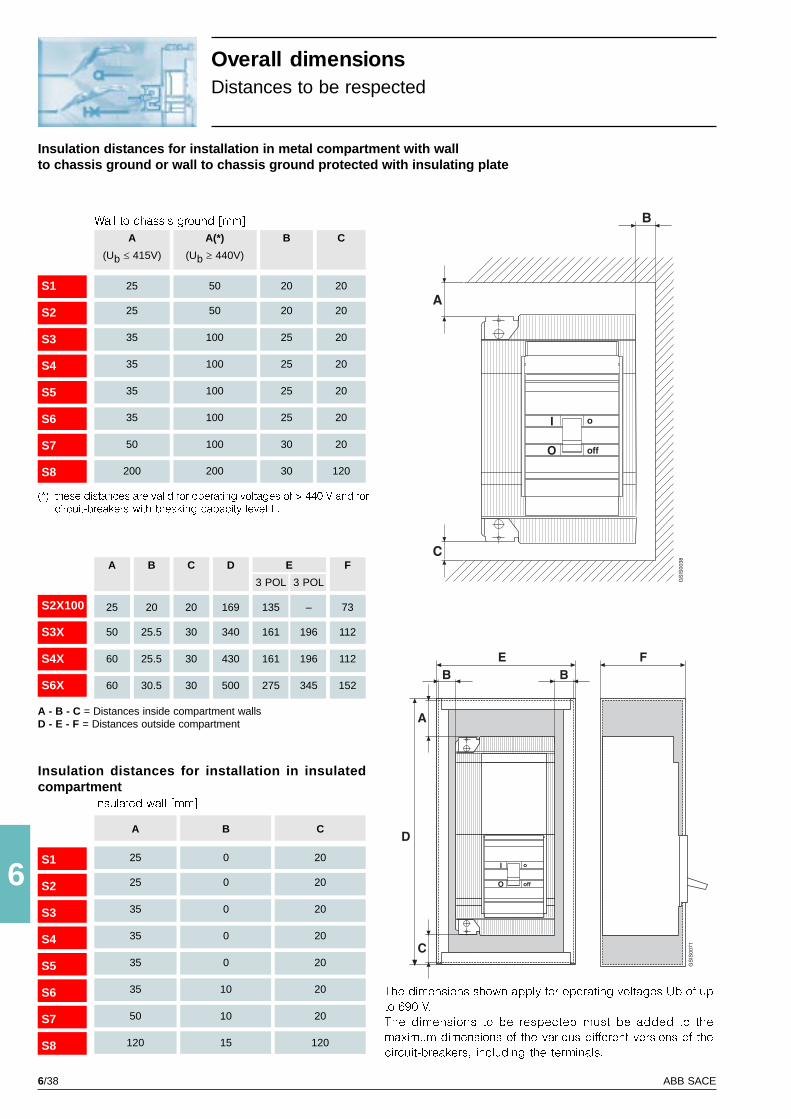
6/38 ABB SACE
6
I
O
o
off
B
A
C
GS
IS00
38
S1
S2
S3
S4
S5
S6
S7
S8
A(*)
(Ub ³ 440V)
50
50
100
100
100
100
100
200
A
(Ub £ 415V)
25
25
35
35
35
35
50
200
B
20
20
25
25
25
25
30
30
C
20
20
20
20
20
20
20
120
S1
S2
S3
S4
S5
S6
S7
S8
B
0
0
0
0
0
10
10
15
A
25
25
35
35
35
35
50
120
C
20
20
20
20
20
20
20
120
S2X100
S3X
S4X
S6X
A
25
50
60
60
C
20
30
30
30
B
20
25.5
25.5
30.5
D
169
340
430
500
F
73
112
112
152
E
3 POL 3 POL
135 –
161 196
161 196
275 345
I
O
o
off
A
D
C
B BE F
GS
IS00
71
Wall to chassis ground [mm]
(*) these distances are valid for operating voltages of > 440 V and forcircuit-breakers with breaking capacity level L.
A - B - C = Distances inside compartment wallsD - E - F = Distances outside compartment
Insulated wall [mm]
Insulation distances for installation in insulatedcompartment
The dimensions shown apply for operating voltages Ub of up
to 690 V.
The dimensions to be respected must be added to the
maximum dimensions of the various different versions of the
circuit-breakers, including the terminals.
Overall dimensionsDistances to be respected
Insulation distances for installation in metal compartment with wallto chassis ground or wall to chassis ground protected with insulating plate
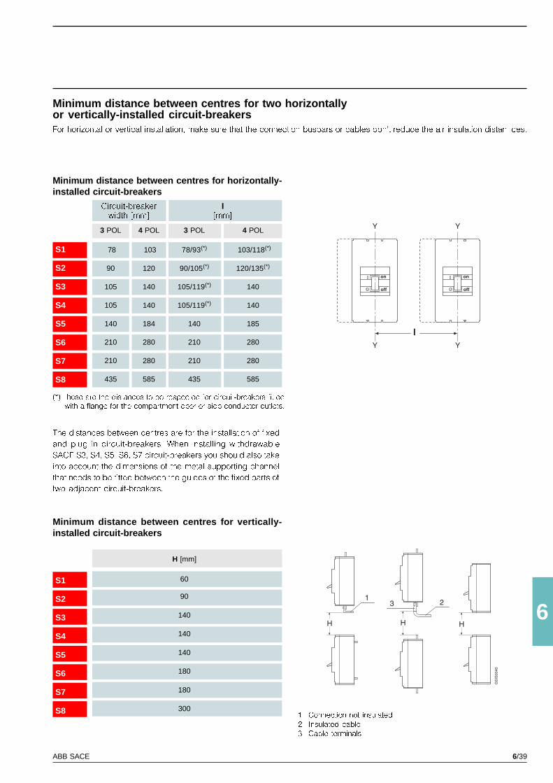
6/39ABB SACE
6
on
off
Y
Y
on
off
Y
Y
l
HHH
123
GS
IS00
40
S1
S2
S3
S4
S5
S6
S7
S8
3 POL
78
90
105
105
140
210
210
435
4 POL
103
120
140
140
184
280
280
585
3 POL
78/93(*)
90/105(*)
105/119(*)
105/119(*)
140
210
210
435
4 POL
103/118(*)
120/135(*)
140
140
185
280
280
585
S1
S2
S3
S4
S5
S6
S7
S8
H [mm]
60
90
140
140
140
180
180
3001 Connection not insulated
2 Insulated cable
3 Cable terminals
The distances between centres are for the installation of fixed
and plug in circuit-breakers. When installing withdrawable
SACE S3, S4, S5, S6, S7 circuit-breakers you should also take
into account the dimensions of the metal supporting channel
that needs to be fitted between the guides of the fixed parts of
two adjacent circuit-breakers.
Minimum distance between centres for vertically-installed circuit-breakers
(*) these are the distances to be respected for circuit-breakers fittedwith a flange for the compartment door or side conductor outlets.
Minimum distance between centres for horizontally-installed circuit-breakers
Minimum distance between centres for two horizontallyor vertically-installed circuit-breakersFor horizontal or vertical installation, make sure that the connection busbars or cables don�t reduce the air insulation distan ces.
Circuit-breakerwidth [mm]
I[mm]

6/40 ABB SACE
6/41ABB SACE
6
Index
Operating status shown ................................................................................................. 6/42
Duty releases ..................................................................................................................... 6/44
Auxiliary contacts ............................................................................................................. 6/46
Position contacts ............................................................................................................. 6/48
Auxiliary circuits of electronic releases ........................................................................ 6/50
Motor operators ................................................................................................................ 6/53
Graphic symbols for circuit-diagrams (IEC 617 and CEI 3-14 … 3-26) ..................... 6/54
Key and reference notes ................................................................................................. 6/55
Circuit-diagrams

6/42 ABB SACE
6
SACE S1-S2-S3-S5-S6 SACE S3D-S6D-S7D-S8D
SACE S1-S2-S3
GS
IS00
45
GS
IS00
46
GS
IS00
47
GS
IS00
48
RC211RC212
RC210RC211RC212
Circuit diagramsOperating status shown
Three-pole or four-pole circuit-breakerwith thermomagnetic release
Three-pole or four-poleswitch-disconnector
Four-pole fixed circuit-breakerwith vertically-installed residual-current release
SACE RC211 o RC212
Four-pole fixed circuit-breaker withhorizontally-installed residual-current release
SACE RC210, RC211 o RC212
The circuit is shown in the following conditions:
- fixed, plug in or withdrawable circuit-breaker (depending
on type of circuit-breaker), open and racked in
- circuits de-energised
- releases not tripped
- motor operator with springs loaded (for S6-S7 circuit-break-
ers)
The circuit-breaker is only fitted with those accessories speci-
fied in the ABB SACE confirmation of order. Consult this cata-
logue for information on how to make out an order.

6/43ABB SACE
6
GS
IS00
53
SACE S4-S5-S6-S7
SACE S4-S5-S6-S7
GS
IS00
49
GS
IS00
50
GS
IS00
51
GS
IS00
52 Inte
rnal
circ
uit
Ext
erna
lci
rcui
tE
xter
nal
circ
uit
Circuit of currenttransformer on neutralconductor outside circuit-breaker (for withdrawablecircuit-breaker)
Term.X5
Term.X5
Three-pole or four-pole circuit-breakerwith SACE PR211/P
microprocessor-based release
Three-pole or four-pole circuit-breakerwith SACE PR212/P
microprocessor-based release
Three-pole fixed circuit-breakerwith current transformer on neutralconductor outside circuit-breaker
N.B. If using a fixed circuit-breaker with a current trans-
former on the neutral conductor outside the circuit-
breaker, you must short-circuit the terminals of the TI/N
transformer when you want to remove the circuit-
breaker.
Three-pole plug-in or withdrawablecircuit-breaker with current transformer onneutral conductor outside circuit-breaker
Three-pole circuit-breakerwith SACE PR212/MP
microprocessor-based release

6/44 ABB SACE
6
SACE S3
SACE S1-S2
GS
IS00
54
GS
IS00
55
Openingrelease
Openingsolenoid ofSACE RC211residual-currentrelease
Opening solenoidof SACE RC212residual-currentrelease
Instantaneousundervoltagerelease
Inte
rnal
circ
uit
Ext
erna
lci
rcui
tE
xter
nal
circ
uit
Version of instantaneousundervoltage release formachine tools
Undervoltage release withelectronic time-lag deviceoutside the circuit-breaker
Inte
rnal
circ
uit
Ext
erna
lci
rcui
tE
xter
nal
circ
uit
Openingrelease
Openingsolenoid ofSACE RC211residual-currentrelease
Opening solenoidof SACE RC212residual-currentrelease
Instantaneousundervoltagerelease
Term. XV
Term. XV
Conn. X1
Conn. X1
Circuit diagramsDuty releases

6/45ABB SACE
6
SACE S4-S5
SACE S6-S7
GS
IS00
56
GS
IS00
57
IncompatibilityThe circuits indicated in the fol-lowing figures cannot be poweredsimultaneously on the same cir-cuit-breaker
1 - 4 - 5 - 6 2 - 3
AvailabilityConnectors X1 and X2 are onlysupplied to order for circuit-break-ers S1 - S2.
Notes(*A) The undervoltage release ispowered from upstream of the cir-cuit-breaker or by an independentpower supply: closing of the cir-cuit-breaker is only allowed whenthe release is energised (the clos-ing lock is implemented mechani-cally).
(*B) Contact S4 shown in Fig. 5opens the circuit when the circuit-breaker is open and closes it againupon a manual closing commandfrom the rotary handle, in con-formity with the Standards gov-erning machine tools (the circuit-breaker will not close, however, ifthe undervoltage release is notpowered).
Version of instantaneousundervoltage release formachine tools
Undervoltage release withelectronic time-lag deviceoutside the circuit-breaker
Openingrelease
Instantaneousundervoltagerelease
Undervoltage release withelectronic time-lag deviceoutside the circuit-breaker
Openingrelease
Instantaneousundervoltagerelease
Term. XV
Inte
rnal
circ
uit
Ext
erna
lci
rcui
tE
xter
nal
circ
uit
Term. XV
Term. XV
Inte
rnal
circ
uit
Ext
erna
lci
rcui
tE
xter
nal
circ
uit
Term. XV
Conn. X1
Conn. X1
Conn. X1
Conn. X1

6/46 ABB SACE
6
SACE S1-S2
SACE S3-S4-S5-S6-S7
GS
IS00
59G
SIS
0058
Two change-overcontacts for electricalsignalling of circuit-breaker open/closed
One change-over contact for electrical signallingof circuit-breaker open or closed and one change-over contact for electrical signalling of circuit-breaker open due to tripping of thermomagneticreleases YO, YO1, YU (tripped position)
Inte
rnal
circ
uit
Ext
erna
lci
rcui
tE
xter
nal
circ
uit
Inte
rnal
circ
uit
Ext
erna
lci
rcui
tE
xter
nal
circ
uit
Term. XV
Term. XV
Conn. X2
Conn. X2
Circuit diagramsAuxiliary contacts
Conn. X2
Conn. X2
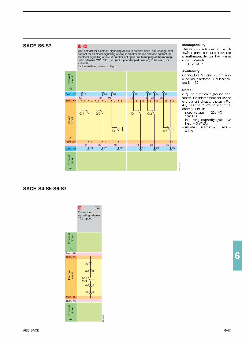
6/47ABB SACE
6
SACE S6-S7
SACE S4-S5-S6-S7
GS
IS00
80
GS
IS00
60
One contact for electrical signalling of circuit-breaker open, one change-overcontact for electrical signalling of circuit-breaker closed and one contact forelectrical signalling of circuit-breaker not open due to tripping of thermomag-netic releases YO1, YO1, YU (not tripped/tripped position) to be used, forexample,for the enabling shown in Fig.8
Contact forsignalling releaseY01 tripped
IncompatibilityThe circuits indicated in the fol-lowing figures cannot be poweredsimultaneously on the samecircuit-breaker: 11-12-13-14
AvailabilityConnectors X1 and X2 are onlysupplied to order for circuit-break-ers S1 - S2.
Notes(*C) The electrical signalling con-tact for the microprocessor-basedovercurrent release, shown in Fig.41, has the following electricalcharacteristics:� rated voltage = 125V AC /
30V DC� breaking capacity (resistive
load = 3 W/VA)� maximum interrupted current =
0.5 A
Inte
rnal
circ
uit
Ext
erna
lci
rcui
tE
xter
nal
circ
uit
Term. XV
Term. XV
Term. X5
Inte
rnal
circ
uit
Ext
erna
lci
rcui
tE
xter
nal
circ
uit
Term. X6
Term. X6
Term. X5
Conn. X2
Conn. X2
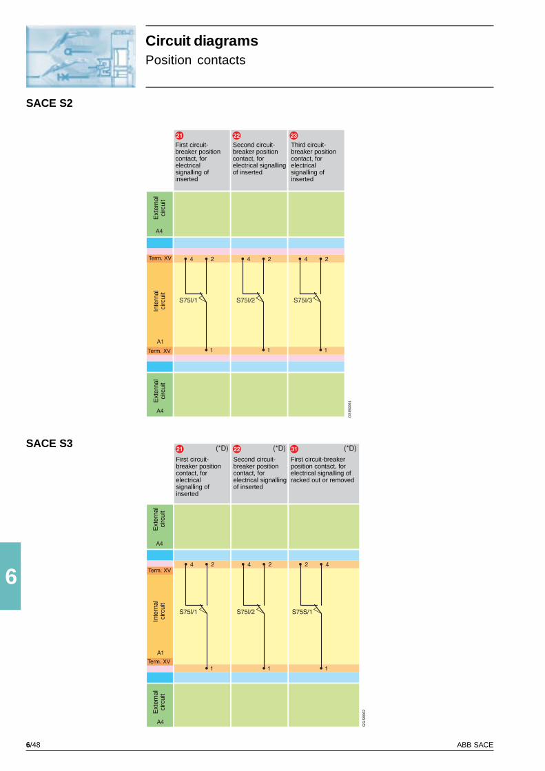
6/48 ABB SACE
6
SACE S2
SACE S3
GS
IS00
61
GS
IS00
62
First circuit-breaker positioncontact, forelectricalsignalling ofinserted
Second circuit-breaker positioncontact, forelectrical signallingof inserted
Third circuit-breaker positioncontact, forelectricalsignalling ofinserted
First circuit-breakerposition contact, forelectrical signalling ofracked out or removed
First circuit-breaker positioncontact, forelectricalsignalling ofinserted
Second circuit-breaker positioncontact, forelectrical signallingof inserted
Term. XV
Inte
rnal
circ
uit
Ext
erna
lci
rcui
tE
xter
nal
circ
uit
Term. XV
Term. XV
Inte
rnal
circ
uit
Ext
erna
lci
rcui
tE
xter
nal
circ
uit
Term. XV
Circuit diagramsPosition contacts

6/49ABB SACE
6
SACE S6-S7
SACE S4-S5
GS
IS00
63
GS
IS00
64
IncompatibilityThe circuitsindicated in thefollowing figurescannot be poweredsimultaneously onthe same circuit-breaker:
20 - 21 - 3122 - 32 23 - 3324 - 34 25 - 35
Notes(*D) The circuit-breaker can befitted with positioncontacts S75I andS75S in anycombination up to amaximum of� total of 2 contacts
for S3� total of 3 contacts
for S4, S5� total of 5 contacts
for S6, S7
First circuit-breaker positioncontact, forelectricalsignalling ofinserted
Second circuit-breaker positioncontact, forelectricalsignalling ofinserted
Third circuit-breaker positioncontact, forelectricalsignalling ofinserted
First circuit-breakerposition contact, forelectrical signalling ofracked out orremoved
Second circuit-breaker positioncontact, for electricalsignalling of rackedout or removed
Third circuit-breakerposition contact, forelectrical signalling ofracked out orremoved
Term. XV
Inte
rnal
circ
uit
Ext
erna
lci
rcui
tE
xter
nal
circ
uit
Term. XV
Term. XV
Inte
rnal
circ
uit
Term. XV
Firs
t circ
uit-
brea
ker
posi
tion
cont
act,
for
elec
tric
al s
igna
lling
of
inse
rted
Sec
ond
circ
uit-
brea
ker
posi
tion
cont
act,
for
elec
tric
al s
igna
lling
of
inse
rted
Thi
rd c
ircui
t-br
eake
r po
sitio
nco
ntac
t, fo
r el
ectr
ical
sig
nalli
ng o
fin
sert
ed
Fou
rth
circ
uit-
brea
ker
posi
tion
cont
act,
for
elec
tric
al s
igna
lling
of
inse
rted
Fift
h ci
rcui
t-br
eake
r po
sitio
nco
ntac
t, fo
r el
ectr
ical
sig
nalli
ng o
fin
sert
ed
Firs
t circ
uit-
brea
ker
posi
tion
cont
act,
for
elec
tric
al s
igna
lling
of
rack
ed o
ut
Sec
ond
circ
uit-
brea
ker
posi
tion
cont
act,
for
elec
tric
al s
igna
lling
of
rack
ed o
ut
Thi
rd c
ircui
t-br
eake
r po
sitio
nco
ntac
t, fo
r el
ectr
ical
sig
nalli
ng o
fra
cked
out
Fou
rth
circ
uit-
brea
ker
posi
tion
cont
act,
for
elec
tric
al s
igna
lling
of
rack
ed o
ut
Fift
h ci
rcui
t-br
eake
r po
sitio
nco
ntac
t, fo
r el
ectr
ical
sig
nalli
ng o
fra
cked
out
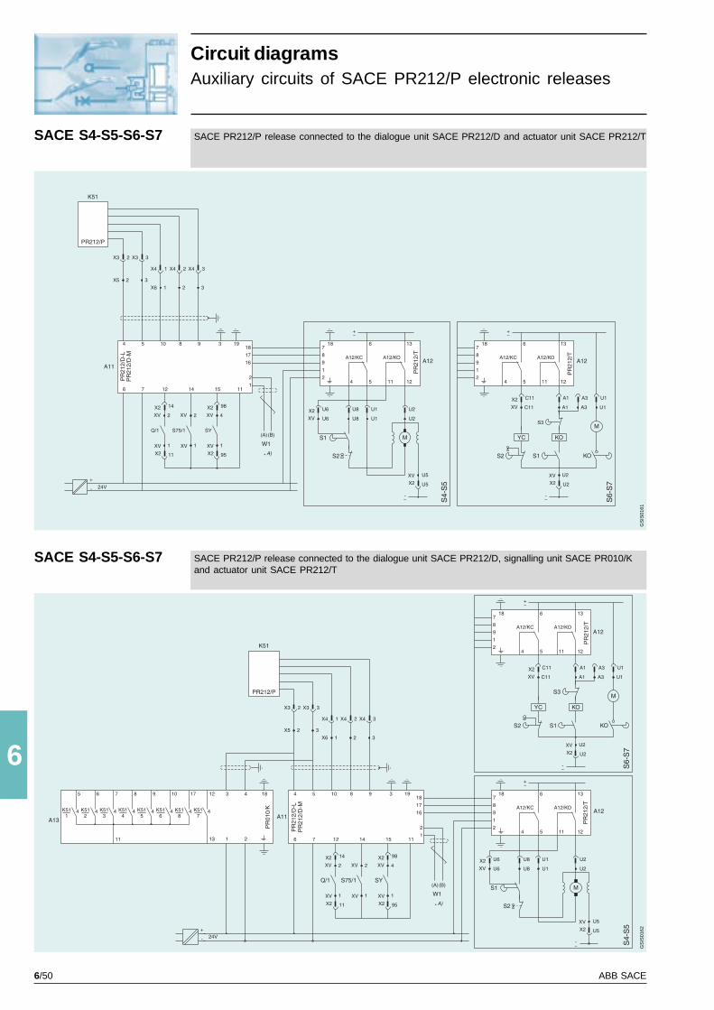
6/50 ABB SACE
6
SACE S4-S5-S6-S7
SACE S4-S5-S6-S7
GS
IS01
61G
SIS
0162
Circuit diagramsAuxiliary circuits of SACE PR212/P electronic releases
SACE PR212/P release connected to the dialogue unit SACE PR212/D and actuator unit SACE PR212/T
SACE PR212/P release connected to the dialogue unit SACE PR212/D, signalling unit SACE PR010/Kand actuator unit SACE PR212/T

6/51ABB SACE
6
SACE S4-S5-S6-S7
SACE S4-S5-S6-S7
GS
IS01
63G
SIS
0164
Circuit diagramsAuxiliary circuits of SACE PR212/MP electronic releasesfor motor protection
SACE PR212/MP release connected to the dialogue unit SACE PR212/D-L, actuator unitSACE PR212/T and contactor operator unit SACE PR212/CI
SACE PR212/MP release connected to the dialogue unit SACE PR212/D-L and actuator unitSACE PR212/T

6/52 ABB SACE
6
GSSC0318
GSSC0319
SACE S4-S5-S6-S7
SACE S4-S5-S6-S7
GS
IS01
65G
SIS
0166
SACE PR212/MP release connected to the signalling unit SACE PR010/K and contactor operator unitSACE PR212/CI
SACE PR212/MP release connected to the dialogue unit SACE PR212/D-L, actuator unitSACE PR212/T, signalling unit SACE PR010/K and contactor operator unit SACE PR212/CI
Circuit diagramsAuxiliary circuits of SACE PR212/MP electronic releasesfor motor protection
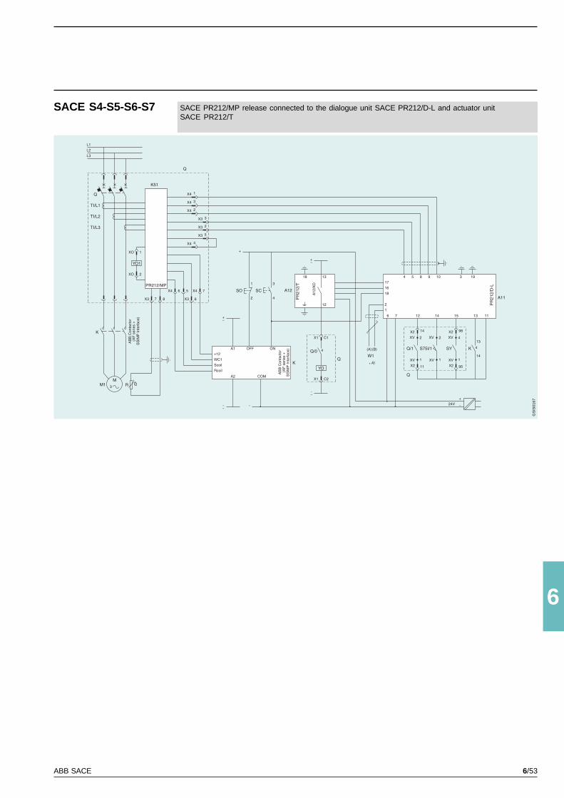
6/53ABB SACE
6
SACE S4-S5-S6-S7
GS
IS01
67
SACE PR212/MP release connected to the dialogue unit SACE PR212/D-L and actuator unitSACE PR212/T

6/54 ABB SACE
6
SACE S3-S4-S5
SACE S6-S7
SACE S1-S2
GS
IS00
81
GS
IS00
65
GS
IS00
66
Direct action motor operator
Stored-energy motor operator
Term. XV
Conn. X2In
tern
alci
rcui
tE
xter
nal
circ
uit
Conn. X2
Term. XV
Term. XV
Conn. X2
Inte
rnal
circ
uit
Ext
erna
lci
rcui
tE
xter
nal
circ
uit
Conn. X2
Term. XV
Ext
erna
lci
rcui
t
Circuit diagramsMotor operators
Solenoid operator
Conn. X2
Inte
rnal
circ
uit
Ext
erna
lci
rcui
t
Conn. X2
Ext
erna
lci
rcui
t

6/55ABB SACE
6
Circuit diagramsGraphic symbols for circuit diagrams(Standards IEC 617 and CEI 3-14...3-26)
Thermal effect
Electromagnetic effect
Time delay
Mechanicalconnection
Manual mechanical control(general case)
Pushbutton actuator
Key control
Cam control
Earth (general symbol)
Equipotentiality
Galvanically separatedconverter
Shielded cable conductors(example: two conductors)
Conductors or stranded cables(example: two conductors)
Connection of conductors
Make contact withheld position
Make position contact(limit contact)
Opening position contact (limitcontact)
Change-over position contactwith temporary interruption (limitcontact)
Switch-disconnector
Contactor (closing contact)
Circuit-breaker with automaticrelease
Control coil (general symbol)
Instantaneous overcurrentrelay
Overcurrent relay withadjustable short time-delay trip
Overcurrent relay with shortinverse time-delay trip
Overcurrent relay with inverselong time delay
Earth fault overcurrent relay withinverse short time-delay trip
Residual current relay
Terminal or clamp
Socket (female) or pole of asocket
Socket and plug (female andmale)
Temperature dependentresistor
Resistor (general symbol)
Induction motor, threephase,squirrel cage
Motor (general symbol)
Brush
Motor energisedin series
Current transformer with primaryformed by 4 through conductorsand wound secondary, withsocket
Current transformer
Make contact
Break contact
Change-over contact withtemporary interruption

6/56 ABB SACE
6
= Figure number of diagram
* = See the note indicated by the letter
A1 = Applications of the circuit-breaker
A2 = Applications of the motor operators
A4 = Example switchgear and connections for control and
signalling, outside the circuit-breaker
A11 = PR212/D-L dialogue unit, for connection to a centralised
control system
A12 = PR212/T actuator unit, with auxiliary relays for execut-
ing commands from the dialogue unit
A12/KC = Actuator unit closing control
A12/KO = Actuator unit opening control
A13 = PR010/K signalling unit with auxiliary relays for electrical
signalling of the protection functions of the microproc-
essor-based overcurrent release
A14 = Interface unit with SACE PR212/CI operator unit
D = Electronic time-lag device of undervoltage release (out-
side the circuit-breaker)
K51 = PR211, PR212/P or PR212/MP microprocessor-based
overcurrent release with the following protection func-
tions:
- L overload protection with inverse long time-delay trip
- S short-circuit protection with inverse or definite short
time-delay trip (only available with PR212/P release)
- I short-circuit protection with instantaneous trip
- G earth fault protection with inverse short time-delay
trip (only available with PR212/P release)
K51/X = Electrical signalling of alarm for internal communication
fault
K51/X = Electrical signalling of alarm for protection function G in
tripping zone
K51/X = Electrical signalling of alarm for protection function I in
tripping zone
K51/X = Electrical signalling of alarm for protection function L in
tripping zone
K51/X = Electrical signalling for protection function L in pre-alarm
zone
K51/X = Electrical signalling of alarm for protection function S in
tripping zone
K51/X = Electrical signalling of alarm for release YO1 tripped
due to overcurrent or �trip test� (Fig. 41)
K87 = RC211-RC212 residual-current release (for circuit-
breakers S1-S2-S3) or RC210 (for circuit-breaker S1)
KO = For S3 - S4 - S5: auxiliary opening relay.
For S6 - S7: opening and spring-loading relay with held-
position make contact, released by a cam of the motor
operator when the circuit-breaker reaches its open po-
sition and the closing springs have been loaded
M = For S3 - S4 - S5: motor with energising in series for
opening and closing of the circuit-breaker. For S6 - S7:
motor for opening the circuit-breaker and loading the
closing springs of the circuit-breaker
M1 = Three-phase asinchronous motor
Q = Main switch
Q/0 ... 2 = Auxiliary contacts of the circuit-breaker
R = Resistor outside the circuit-breaker, supplied for motor
power supply voltages of more than 220 V
S1 = For S3 - S4 - S5: position contact operated by a circuit-
breaker cam For S6 - S7: contact controlled by the
motor operator cam: closes when the circuit-breaker
reaches its closed position and opens when the circuit-
breaker reaches its open position (doesn�t switch when
the circuit-breaker goes into its tripped position)
S2 = For S3 - S4 - S5: safety contact operated by:
- key lock (if fitted)
- padlock device
- manual control selector.
For S6 - S7: contact controlled by the motor operator
cam: opens when the circuit-breaker reaches its closed
position and closes when the circuit-breaker reaches
its open position (doesn�t switch when the circuit-breaker
goes into its tripped position).The contact is also oper-
ated by the key lock device (if present)
S3 = Contact controlled by the motor operator cam: opens
after contact KO has closed and closes when the cir-
cuit-breaker reaches its open position (doesn�t switch
when the circuit-breaker goes into its tripped position)
S4 = Contact operated by the circuit-breaker rotary handle
S75I/1...5 = Contacts for electrical signalling of circuit-breaker in
inserted position (only for plug in or withdrawable cir-
cuit-breakers)
S75S/1...5 = Contacts for electrical signalling of circuit-breaker in
removed or racked-out position (only for plug in or with-
drawable circuit-breakers)
SC = Pushbutton or contact for closing the circuit-breaker or
for motor start. For circuit-breakers S3 - S4 - S5, the
operating mechanism must have a time of not less than
100ms
SO = Pushbutton or contact for opening the circuit-breaker
or for motor stop
SO1, S02 = Pushbuttons or contacts for opening the circuit-breaker.
For circuit-breakers S3 - S4 - S5, the operating mecha-
nism must have a time of not less than 100 ms (see
�Instructions for resetting the circuit-breaker after the
releases have tripped�)
SY = Contact for electrical signalling of circuit-breaker open
due to tripping of thermomagnetic releases, YO, YO1,
YU (tripped position)
TI = Toroidal current transformer
TI/L1 = Current transformer located on phase L1
TI/L2 = Current transformer located on phase L2
TI/L3 = Current transformer located on phase L3
TI/N = Current transformer located on neutral
Circuit diagramsKey and notes

6/57ABB SACE
6
GS
IS00
67
3) Electrical resetting always enabled
The electrical opening control (contact SO2) is connected in se-
ries directly to relay KO for S3 - S4 - S5 or connected directly to
pole A3 of connector X2 (for S6 - S7) and is therefore always
enabled.
Example of use: automatic resetting of the circuit-breaker imme-
diately after the releases have been tripped
N.B. If an overcurrent release is fitted, it will be necessary to
identify the causes that brought it to its tripped position in order
to prevent it from closing again in short-circuit conditions.
Manual resetting is always allowed in each of these examples.
W1 = Serial interface with monitoring system (EIA RS485 in-
terface)
X1, X2 = Connectors for the auxiliary circuits of the circuit-breaker.
For circuit-breakers S1 - S2 supplied to order only.
X3, X4 = Connectors for the circuits of the microprocessor-based
overcurrent release (with plug in or withdrawable cir-
cuit-breakers, the connectors are pulled out at the same
time as the circuit-breaker)
X5, X6 = Terminal delivery block for microprocessor-based
overcurrent release circuits
XO = Connector for the opening solenoid YO1
XV = Terminal blocks for accessories
YC = Closing release
YO = Opening release
YO1 = Opening solenoid of the RC211 or RC212 residual cur-
rent release (for S1 - S2 - S3) and of the overcurrent
release (for S4 ... S8)
YU = Undervoltage release
Instructions for resetting the circuit-breaker after the releases
have tripped
The circuit-breaker can open both through the action of the motor
operator and due to the following releases tripping:
� overcurrent
� undervoltage
� opening
with consequent opening of contact SY (if fitted) in series with relay
KO.
A reset operation involving manual or electric opening will have to be
carried out in order to close the circuit-breaker again after tripping.
Contact SY closes again at the end of the operation. The type of
resetting should be chosen to suit the design requirements and duty
conditions. A number of possible solutions are suggested below:
1) Manual resetting only
The electrical opening control (contact SO1) must be connected
in series with contact SY. Opening (for S3 - S4 - S5 using the
auxiliary relay KO) is therefore prevented until the circuit-breaker
is in its tripped position. To reset the circuit-breaker one needs to
operate the related lever until the circuit-breaker is in its open
position and the closing springs are fully loaded.
2) Electrical resetting, responsibility of the operator
The normal electric opening control (contact SO1) must be con-
nected in series with contact SY.
Another opening control is provided (contact SO2), connected
in series directly to relay KO for S3 - S4 - S5 or connected directly
to pole A3 of connector X2 for S6 - S7.
This control must be protected by, for example, a pushbutton
keyswitch. It should only be used if the information relayed to the
control station manager allows one to rule out the possibility of the
tripping having been caused by a short circuit, or if the causes of
the short circuit have been removed.
Conn.X1
Inte
rnal
circ
uit
Ext
erna
lci
rcui
tE
xter
nal
circ
uit
Term.XV
Conn.X1
Term.XV
Circuit diagramsGraphic symbols for circuit diagrams(Standards IEC 617 and CEI 3-14...3-26)

6/58 ABB SACE
7/1
7
ABB SACE
Order codes
Index
General information .......................................................................................................... 7/2
Circuit-breakers for power distribution
SACE Isomax S1 ................................................................................................... 7/3
SACE Isomax S2 ................................................................................................... 7/6
SACE Isomax S3 ................................................................................................... 7/13
SACE Isomax S4 ................................................................................................... 7/26
SACE Isomax S5 ................................................................................................... 7/32
SACE Isomax S6 ................................................................................................... 7/41
SACE Isomax S7 ................................................................................................... 7/47
SACE Isomax S8 ................................................................................................... 7/51
Current-limiting circuit-breakers
SACE Isomax S2X 100 ......................................................................................... 7/52
SACE Isomax S3X ................................................................................................. 7/53
SACE Isomax S4X ................................................................................................. 7/56
SACE Isomax S6X ................................................................................................. 7/58
Circuit-breakers for motor protection
SACE Isomax S2X 80 ........................................................................................... 7/60
SACE Isomax S3 ................................................................................................... 7/61
SACE Isomax S4 ................................................................................................... 7/62
SACE Isomax S5 ................................................................................................... 7/63
SACE Isomax S6 ................................................................................................... 7/63
SACE Isomax S7 ................................................................................................... 7/63
SACE Isomax S3X-S4X-S6X ................................................................................ 7/64
Circuit-breakers for applications up to 1000 V .............................................................. 7/65
Switch-disconnectors
SACE Isomax S2D ................................................................................................ 7/67
SACE Isomax S3D ................................................................................................ 7/68
SACE Isomax S6D ................................................................................................ 7/70
SACE Isomax S7D ................................................................................................ 7/71
SACE Isomax S8D ................................................................................................ 7/72
Accessories ....................................................................................................................... 7/73
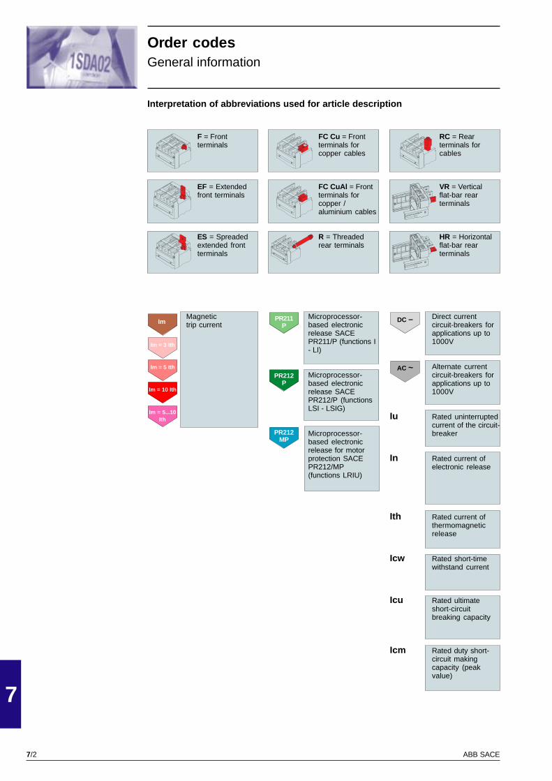
7/2
7
ABB SACE
Order codesGeneral information
F = Frontterminals
EF = Extendedfront terminals
ES = Spreadedextended frontterminals
Interpretation of abbreviations used for article description
Direct currentcircuit-breakers forapplications up to1000V
Alternate currentcircuit-breakers forapplications up to1000V
Iu Rated uninterruptedcurrent of the circuit-breaker
In Rated current ofelectronic release
Ith Rated current ofthermomagneticrelease
Icw Rated short-timewithstand current
Icu Rated ultimateshort-circuitbreaking capacity
Icm Rated duty short-circuit makingcapacity (peakvalue)
Microprocessor-based electronicrelease SACEPR211/P (functions I- LI)
Microprocessor-based electronicrelease SACEPR212/P (functionsLSI - LSIG)
Microprocessor-based electronicrelease for motorprotection SACEPR212/MP(functions LRIU)
FC Cu = Frontterminals forcopper cables
FC CuAl = Frontterminals forcopper /aluminium cables
R = Threadedrear terminals
RC = Rearterminals forcables
VR = Verticalflat-bar rearterminals
HR = Horizontalflat-bar rearterminals
Magnetictrip current
PR211P
Im = 3 Ith
Im = 5 Ith
Im = 10 Ith
PR212P
PR212MP
Im
AC ~
DC –
Im = 5...10Ith

7/3
7
ABB SACE
PSIS9601
Order codesSACE Isomax S1 circuit-breaker
F = FIXED S1B 125 Iu (40 °C) = 125 A Icu (415 V) = 16 kAThermomagnetic code 1SDA0 . . . . . R1 code 1SDA0 . . . . . R1release 3 poles 4 poles 3 poles 4 polesFC Cu = Front terminalsfor copper cablesS1B 125 F FC Cu R 10 160A 23645 24245 500A 00002 00052S1B 125 F FC Cu R 12.5 160A 23647 24247 500A 00004 00054S1B 125 F FC Cu R 16 160A 23649 24249 500A 00006 00056S1B 125 F FC Cu R 20 200A 23651 24251 500A 00008 00058S1B 125 F FC Cu R 25 200A 23653 24253 500A 00010 00060S1B 125 F FC Cu R 32 200A 23655 24255 500A 00012 00062S1B 125 F FC Cu R 40 200A 23657 24257 500A 00014 00064S1B 125 F FC Cu R 50 250A 23659 24259 500A 00016 00066S1B 125 F FC Cu R 63 320A 23661 24261 630A 00018 00068S1B 125 F FC Cu R 80 400A 23663 24263 800A 00020 00070S1B 125 F FC Cu R 100 500A 23665 24265 1000A 00022 00072S1B 125 F FC Cu R 125 630A 23667 24267 1250A 00024 00074R = Terminali posteriori filettatiS1B 125 F R R 10 160A 23765 23885 500A 00027 00077S1B 125 F R R 12.5 160A 23767 23887 500A 00029 00079S1B 125 F R R 16 160A 23769 23889 500A 00031 00081S1B 125 F R R 20 200A 23771 23891 500A 00033 00083S1B 125 F R R 25 200A 23773 23893 500A 00035 00085S1B 125 F R R 32 200A 23775 23895 500A 00037 00087S1B 125 F R R 40 200A 23777 23897 500A 00039 00089S1B 125 F R R 50 250A 23779 23899 500A 00041 00091S1B 125 F R R 63 320A 23781 23901 630A 00043 00093S1B 125 F R R 80 400A 23783 23903 800A 00045 00095S1B 125 F R R 100 500A 23785 23905 1000A 00047 00097S1B 125 F R R 125 630A 23787 23907 1250A 00049 00099
Im = 10 IthIm = 5 Ith

7/4
7
ABB SACE
PSIS9601
S1N 125 Iu (40 °C) = 125 A Icu (415 V) = 25 kAThermomagnetic code 1SDA0 . . . . . R1 code 1SDA0 . . . . . R1release 3 poles 4 poles 3 poles 4 polesFC Cu = Front terminalsfor copper cablesS1N 125 F FC Cu R 10 160A 23669 24269 500A 00152 00202S1N 125 F FC Cu R 12.5 160A 23671 24271 500A 00154 00204S1N 125 F FC Cu R 16 160A 23673 24273 500A 00156 00206S1N 125 F FC Cu R 20 200A 23675 24275 500A 00158 00208S1N 125 F FC Cu R 25 200A 23677 24277 500A 00160 00210S1N 125 F FC Cu R 32 200A 23679 24279 500A 00162 00212S1N 125 F FC Cu R 40 200A 23681 24281 500A 00164 00214S1N 125 F FC Cu R 50 250A 23683 24283 500A 00166 00216S1N 125 F FC Cu R 63 320A 23685 24285 630A 00168 00218S1N 125 F FC Cu R 80 400A 23687 24287 800A 00170 00220S1N 125 F FC Cu R 100 500A 23689 24289 1000A 00172 00222S1N 125 F FC Cu R 125 630A 23691 24291 1250A 00174 00224R = Threaded rear terminalsS1N 125 F R R 10 160A 23789 23909 500A 00177 00227S1N 125 F R R 12.5 160A 23791 23911 500A 00179 00229S1N 125 F R R 16 160A 23793 23913 500A 00181 00231S1N 125 F R R 20 200A 23795 23915 500A 00183 00233S1N 125 F R R 25 200A 23797 23917 500A 00185 00235S1N 125 F R R 32 200A 23799 23919 500A 00187 00237S1N 125 F R R 40 200A 23801 23921 500A 00189 00239S1N 125 F R R 50 250A 23803 23923 500A 00191 00241S1N 125 F R R 63 320A 23805 23925 630A 00193 00243S1N 125 F R R 80 400A 23807 23927 800A 00195 00245S1N 125 F R R 100 500A 23809 23929 1000A 00197 00247S1N 125 F R R 125 630A 23811 23931 1250A 00199 00249
Magnetic code 1SDA0 . . . . . R1 code 1SDA0 . . . . . R1release 3 poles 4 poles 3 poles 4 polesFC Cu = Front terminalsfor copper cablesS1N 125 F FC Cu In 16A 160A 33676 33772S1N 125 F FC Cu In 40A 200A 33684 33780S1N 125 F FC Cu In 50A 250A 33686 33782 500A 33662 33758S1N 125 F FC Cu In 63A 320A 33688 33784 630A 33664 33760S1N 125 F FC Cu In 80A 400A 33690 33786 800A 33666 33762S1N 125 F FC Cu In 100A 1000A 33668 33764S1N 125 F FC Cu In 125A 1250A 33670 33766R = Threaded rear terminalsS1N 125 F R In 16A 160A 33724 33820S1N 125 F R In 40A 200A 33732 33828S1N 125 F R In 50A 250A 33734 33830 500A 33710 33806S1N 125 F R In 63A 320A 33736 33832 630A 33712 33808S1N 125 F R In 80A 400A 33738 33834 800A 33714 33810S1N 125 F R In 100A 1000A 33716 33812S1N 125 F R In 125A 1250A 33718 33814
S1N 125 Curva D Iu (40 °C) = 125 A Icu (415 V) = 25 kAThermomagnetic code 1SDA0 . . . . . R1release 4 polesFC Cu = Front terminalsfor copper cablesS1N 125 F FC Cu R 63A 1250A 45084S1N 125 F FC Cu R 80A 1250A 45087S1N 125 F FC Cu R 100A 1400A 45089S1N 125 F FC Cu R 125A 1500A 45091R = Threaded rear terminalsS1N 125 F R R 63A 1250A 45093S1N 125 F R R 80A 1250A 45095S1N 125 F R R 100A 1400A 45097S1N 125 F R R 125A 1500A 45099
Order codesSACE Isomax S1 circuit-breaker
F = FIXED
Im = 5 Ith Im = 10 Ith
Im = 5 Ith Im = 10 Ith
Im = 10 Ith

7/5
7
ABB SACE
PSIS9601
Moving partS1B 125 Iu (40 °C) = 125 A Icu (415 V) = 16 kAThermomagnetic code 1SDA0 . . . . . R1 code 1SDA0 . . . . . R1release 3 poles 4 poles 3 poles 4 polesS1B 125 P MP R 10 160A 24005 24125 500A 00102 00127S1B 125 P MP R 12.5 160A 24007 24127 500A 00104 00129S1B 125 P MP R 16 160A 24009 24129 500A 00106 00131S1B 125 P MP R 20 200A 24011 24131 500A 00108 00133S1B 125 P MP R 25 200A 24013 24133 500A 00110 00135S1B 125 P MP R 32 200A 24015 24135 500A 00112 00137S1B 125 P MP R 40 200A 24017 24137 500A 00114 00139S1B 125 P MP R 50 250A 24019 24139 500A 00116 00141S1B 125 P MP R 63 320A 24021 24141 630A 00118 00143S1B 125 P MP R 80 400A 24023 24143 800A 00120 00145S1B 125 P MP R 100 500A 24025 24145 1000A 00122 00147S1B 125 P MP R 125 630A 24027 24147 1250A 00124 00149
S1N 125 Iu (40 °C) = 125 A Icu (415 V) = 25 kAThermomagnetic code 1SDA0 . . . . . R1 code 1SDA0 . . . . . R1release 3 poles 4 poles 3 poles 4 polesS1N 125 P MP R 10 160A 24029 24149 500A 00252 00277S1N 125 P MP R 12.5 160A 24031 24151 500A 00254 00279S1N 125 P MP R 16 160A 24033 24153 500A 00256 00281S1N 125 P MP R 20 200A 24035 24155 500A 00258 00283S1N 125 P MP R 25 200A 24037 24157 500A 00260 00285S1N 125 P MP R 32 200A 24039 24159 500A 00262 00287S1N 125 P MP R 40 200A 24041 24161 500A 00264 00289S1N 125 P MP R 50 250A 24043 24163 500A 00266 00291S1N 125 P MP R 63 320A 24045 24165 630A 00268 00293S1N 125 P MP R 80 400A 24047 24167 800A 00270 00295S1N 125 P MP R 100 500A 24049 24169 1000A 00272 00297S1N 125 P MP R 125 630A 24051 24171 1250A 00274 00299
Magnetic code 1SDA0 . . . . . R1 code 1SDA0 . . . . . R1release 3 poles 4 poles 3 poles 4 polesS1N 125 P MP In 16A 160A 33964 34012S1N 125 P MP In 40A 200A 33972 34020S1N 125 P MP In 50A 250A 33974 34022 500A 33950 33998S1N 125 P MP In 63A 320A 33976 34024 630A 33952 34000S1N 125 P MP In 80A 400A 33978 34026 800A 33954 34002S1N 125 P MP In 100A 1000A 33956 34004S1N 125 P MP In 125A 1250A 33958 34006
S1N 125 Curva D Iu (40 °C) = 125 A Icu (415 V) = 25 kAThermomagnetic code 1SDA0 . . . . . R1release 4 polesFC Cu = Front terminalsfor copper cablesS1N 125 P MP R 63A 1250A 45101S1N 125 P MP R 80A 1250A 45103S1N 125 P MP R 100A 1400A 45105S1N 125 P MP R 125A 1500A 45107
P = PLUG-IN
Order codesSACE Isomax S1 circuit-breaker
Im = 5 Ith Im = 10 Ith
Im = 5 Ith Im = 10 Ith
Im = 5 Ith Im = 10 Ith
Im = 10 Ith
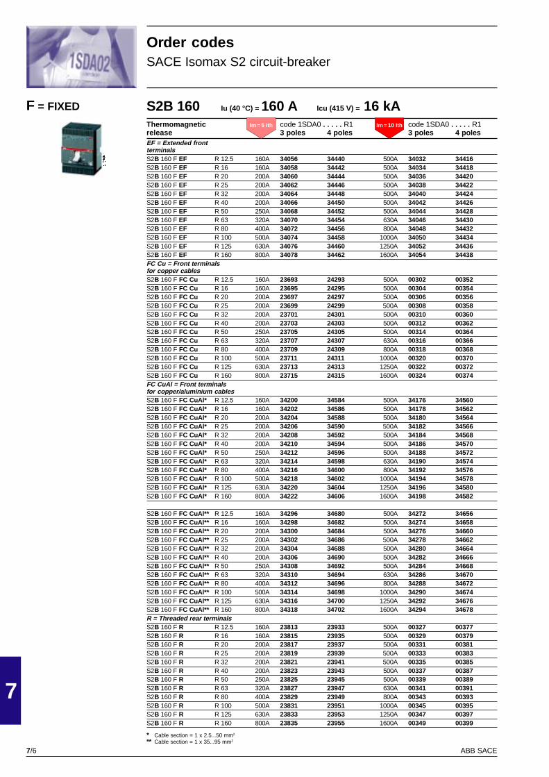
7/6
7
ABB SACE
PSIS9604
S2B 160 Iu (40 °C) = 160 A Icu (415 V) = 16 kAThermomagnetic code 1SDA0 . . . . . R1 code 1SDA0 . . . . . R1release 3 poles 4 poles 3 poles 4 polesEF = Extended frontterminalsS2B 160 F EF R 12.5 160A 34056 34440 500A 34032 34416S2B 160 F EF R 16 160A 34058 34442 500A 34034 34418S2B 160 F EF R 20 200A 34060 34444 500A 34036 34420S2B 160 F EF R 25 200A 34062 34446 500A 34038 34422S2B 160 F EF R 32 200A 34064 34448 500A 34040 34424S2B 160 F EF R 40 200A 34066 34450 500A 34042 34426S2B 160 F EF R 50 250A 34068 34452 500A 34044 34428S2B 160 F EF R 63 320A 34070 34454 630A 34046 34430S2B 160 F EF R 80 400A 34072 34456 800A 34048 34432S2B 160 F EF R 100 500A 34074 34458 1000A 34050 34434S2B 160 F EF R 125 630A 34076 34460 1250A 34052 34436S2B 160 F EF R 160 800A 34078 34462 1600A 34054 34438FC Cu = Front terminalsfor copper cablesS2B 160 F FC Cu R 12.5 160A 23693 24293 500A 00302 00352S2B 160 F FC Cu R 16 160A 23695 24295 500A 00304 00354S2B 160 F FC Cu R 20 200A 23697 24297 500A 00306 00356S2B 160 F FC Cu R 25 200A 23699 24299 500A 00308 00358S2B 160 F FC Cu R 32 200A 23701 24301 500A 00310 00360S2B 160 F FC Cu R 40 200A 23703 24303 500A 00312 00362S2B 160 F FC Cu R 50 250A 23705 24305 500A 00314 00364S2B 160 F FC Cu R 63 320A 23707 24307 630A 00316 00366S2B 160 F FC Cu R 80 400A 23709 24309 800A 00318 00368S2B 160 F FC Cu R 100 500A 23711 24311 1000A 00320 00370S2B 160 F FC Cu R 125 630A 23713 24313 1250A 00322 00372S2B 160 F FC Cu R 160 800A 23715 24315 1600A 00324 00374FC CuAl = Front terminalsfor copper/aluminium cablesS2B 160 F FC CuAl* R 12.5 160A 34200 34584 500A 34176 34560S2B 160 F FC CuAl* R 16 160A 34202 34586 500A 34178 34562S2B 160 F FC CuAl* R 20 200A 34204 34588 500A 34180 34564S2B 160 F FC CuAl* R 25 200A 34206 34590 500A 34182 34566S2B 160 F FC CuAl* R 32 200A 34208 34592 500A 34184 34568S2B 160 F FC CuAl* R 40 200A 34210 34594 500A 34186 34570S2B 160 F FC CuAl* R 50 250A 34212 34596 500A 34188 34572S2B 160 F FC CuAl* R 63 320A 34214 34598 630A 34190 34574S2B 160 F FC CuAl* R 80 400A 34216 34600 800A 34192 34576S2B 160 F FC CuAl* R 100 500A 34218 34602 1000A 34194 34578S2B 160 F FC CuAl* R 125 630A 34220 34604 1250A 34196 34580S2B 160 F FC CuAl* R 160 800A 34222 34606 1600A 34198 34582
S2B 160 F FC CuAl** R 12.5 160A 34296 34680 500A 34272 34656S2B 160 F FC CuAl** R 16 160A 34298 34682 500A 34274 34658S2B 160 F FC CuAl** R 20 200A 34300 34684 500A 34276 34660S2B 160 F FC CuAl** R 25 200A 34302 34686 500A 34278 34662S2B 160 F FC CuAl** R 32 200A 34304 34688 500A 34280 34664S2B 160 F FC CuAl** R 40 200A 34306 34690 500A 34282 34666S2B 160 F FC CuAl** R 50 250A 34308 34692 500A 34284 34668S2B 160 F FC CuAl** R 63 320A 34310 34694 630A 34286 34670S2B 160 F FC CuAl** R 80 400A 34312 34696 800A 34288 34672S2B 160 F FC CuAl** R 100 500A 34314 34698 1000A 34290 34674S2B 160 F FC CuAl** R 125 630A 34316 34700 1250A 34292 34676S2B 160 F FC CuAl** R 160 800A 34318 34702 1600A 34294 34678R = Threaded rear terminalsS2B 160 F R R 12.5 160A 23813 23933 500A 00327 00377S2B 160 F R R 16 160A 23815 23935 500A 00329 00379S2B 160 F R R 20 200A 23817 23937 500A 00331 00381S2B 160 F R R 25 200A 23819 23939 500A 00333 00383S2B 160 F R R 32 200A 23821 23941 500A 00335 00385S2B 160 F R R 40 200A 23823 23943 500A 00337 00387S2B 160 F R R 50 250A 23825 23945 500A 00339 00389S2B 160 F R R 63 320A 23827 23947 630A 00341 00391S2B 160 F R R 80 400A 23829 23949 800A 00343 00393S2B 160 F R R 100 500A 23831 23951 1000A 00345 00395S2B 160 F R R 125 630A 23833 23953 1250A 00347 00397S2B 160 F R R 160 800A 23835 23955 1600A 00349 00399
F = FIXED
Order codesSACE Isomax S2 circuit-breaker
* Cable section = 1 x 2.5...50 mm2
** Cable section = 1 x 35...95 mm2
Im = 5 Ith Im = 10 Ith

7/7
7
ABB SACE
PSIS9604
S2N 160 Iu (40 °C) = 160 A Icu (415 V) = 35 kAThermomagnetic code 1SDA0 . . . . . R1 code 1SDA0 . . . . . R1release 3 poles 4 poles 3 poles 4 polesEF = Extended frontterminalsS2N 160 F EF R 12.5 160A 34826 35210 500A 34802 35186S2N 160 F EF R 16 160A 34828 35212 500A 34804 35188S2N 160 F EF R 20 200A 34830 35214 500A 34806 35190S2N 160 F EF R 25 200A 34832 35216 500A 34808 35192S2N 160 F EF R 32 200A 34834 35218 500A 34810 35194S2N 160 F EF R 40 200A 34836 35220 500A 34812 35196S2N 160 F EF R 50 250A 34838 35222 500A 34814 35198S2N 160 F EF R 63 320A 34840 35224 630A 34816 35200S2N 160 F EF R 80 400A 34842 35226 800A 34818 35202S2N 160 F EF R 100 500A 34844 35228 1000A 34820 35204S2N 160 F EF R 125 630A 34846 35230 1250A 34822 35206S2N 160 F EF R 160 800A 34848 35232 1600A 34824 35208FC Cu = Front terminalsfor copper cablesS2N 160 F FC Cu R 12.5 160A 23717 24317 500A 00452 00502S2N 160 F FC Cu R 16 160A 23719 24319 500A 00454 00504S2N 160 F FC Cu R 20 200A 23721 24321 500A 00456 00506S2N 160 F FC Cu R 25 200A 23723 24323 500A 00458 00508S2N 160 F FC Cu R 32 200A 23725 24325 500A 00460 00510S2N 160 F FC Cu R 40 200A 23727 24327 500A 00462 00512S2N 160 F FC Cu R 50 250A 23729 24329 500A 00464 00514S2N 160 F FC Cu R 63 320A 23731 24331 630A 00466 00516S2N 160 F FC Cu R 80 400A 23733 24333 800A 00468 00518S2N 160 F FC Cu R 100 500A 23735 24335 1000A 00470 00520S2N 160 F FC Cu R 125 630A 23737 24337 1250A 00472 00522S2N 160 F FC Cu R 160 800A 23739 24339 1600A 00474 00524FC CuAl = Front terminalsfor copper/aluminium cablesS2N 160 F FC CuAl* R 12.5 160A 34970 35354 500A 34946 35330S2N 160 F FC CuAl* R 16 160A 34972 35356 500A 34948 35332S2N 160 F FC CuAl* R 20 200A 34974 35358 500A 34950 35334S2N 160 F FC CuAl* R 25 200A 34976 35360 500A 34952 35336S2N 160 F FC CuAl* R 32 200A 34978 35362 500A 34954 35338S2N 160 F FC CuAl* R 40 200A 34980 35364 500A 34956 35340S2N 160 F FC CuAl* R 50 250A 34982 35366 500A 34958 35342S2N 160 F FC CuAl* R 63 320A 34984 35368 630A 34960 35344S2N 160 F FC CuAl* R 80 400A 34986 35370 800A 34962 35346S2N 160 F FC CuAl* R 100 500A 34988 35372 1000A 34964 35348S2N 160 F FC CuAl* R 125 630A 34990 35374 1250A 34966 35350S2N 160 F FC CuAl* R 160 800A 34992 35376 1600A 34968 35352
S2N 160 F FC CuAl** R 12.5 160A 35066 35450 500A 35042 35426S2N 160 F FC CuAl** R 16 160A 35068 35452 500A 35044 35428S2N 160 F FC CuAl** R 20 200A 35070 35454 500A 35046 35430S2N 160 F FC CuAl** R 25 200A 35072 35456 500A 35048 35432S2N 160 F FC CuAl** R 32 200A 35074 35458 500A 35050 35434S2N 160 F FC CuAl** R 40 200A 35076 35460 500A 35052 35436S2N 160 F FC CuAl** R 50 250A 35078 35462 500A 35054 35438S2N 160 F FC CuAl** R 63 320A 35080 35464 630A 35056 35440S2N 160 F FC CuAl** R 80 400A 35082 35466 800A 35058 35442S2N 160 F FC CuAl** R 100 500A 35084 35468 1000A 35060 35444S2N 160 F FC CuAl** R 125 630A 35086 35470 1250A 35062 35446S2N 160 F FC CuAl** R 160 800A 35088 35472 1600A 35064 35448R = Threaded rear terminalsS2N 160 F R R 12.5 160A 23837 23957 500A 00477 00527S2N 160 F R R 16 160A 23839 23959 500A 00479 00529S2N 160 F R R 20 200A 23841 23961 500A 00481 00531S2N 160 F R R 25 200A 23843 23963 500A 00483 00533S2N 160 F R R 32 200A 23845 23965 500A 00485 00535S2N 160 F R R 40 200A 23847 23967 500A 00487 00537S2N 160 F R R 50 250A 23849 23969 500A 00489 00539S2N 160 F R R 63 320A 23851 23971 630A 00491 00541S2N 160 F R R 80 400A 23853 23973 800A 00493 00543S2N 160 F R R 100 500A 23855 23975 1000A 00495 00545S2N 160 F R R 125 630A 23857 23977 1250A 00497 00547S2N 160 F R R 160 800A 23859 23979 1600A 00499 00549
Order codesSACE Isomax S2 circuit-breaker
F = FIXED
* Cable section = 1 x 2.5...50 mm2
** Cable section = 1 x 35...95 mm2
Im = 5 Ith Im = 10 Ith
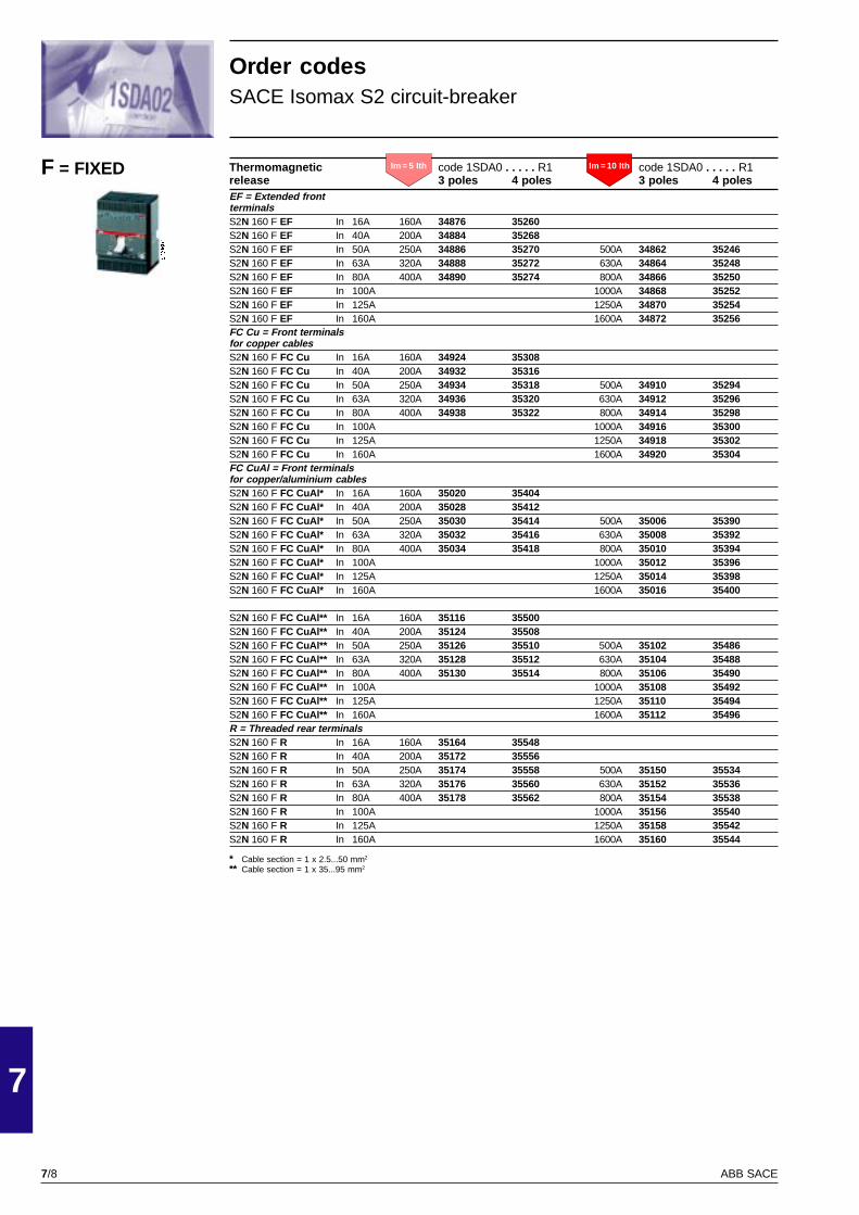
7/8
7
ABB SACE
PSIS9604
Thermomagnetic code 1SDA0 . . . . . R1 code 1SDA0 . . . . . R1release 3 poles 4 poles 3 poles 4 polesEF = Extended frontterminalsS2N 160 F EF In 16A 160A 34876 35260S2N 160 F EF In 40A 200A 34884 35268S2N 160 F EF In 50A 250A 34886 35270 500A 34862 35246S2N 160 F EF In 63A 320A 34888 35272 630A 34864 35248S2N 160 F EF In 80A 400A 34890 35274 800A 34866 35250S2N 160 F EF In 100A 1000A 34868 35252S2N 160 F EF In 125A 1250A 34870 35254S2N 160 F EF In 160A 1600A 34872 35256FC Cu = Front terminalsfor copper cablesS2N 160 F FC Cu In 16A 160A 34924 35308S2N 160 F FC Cu In 40A 200A 34932 35316S2N 160 F FC Cu In 50A 250A 34934 35318 500A 34910 35294S2N 160 F FC Cu In 63A 320A 34936 35320 630A 34912 35296S2N 160 F FC Cu In 80A 400A 34938 35322 800A 34914 35298S2N 160 F FC Cu In 100A 1000A 34916 35300S2N 160 F FC Cu In 125A 1250A 34918 35302S2N 160 F FC Cu In 160A 1600A 34920 35304FC CuAl = Front terminalsfor copper/aluminium cablesS2N 160 F FC CuAl* In 16A 160A 35020 35404S2N 160 F FC CuAl* In 40A 200A 35028 35412S2N 160 F FC CuAl* In 50A 250A 35030 35414 500A 35006 35390S2N 160 F FC CuAl* In 63A 320A 35032 35416 630A 35008 35392S2N 160 F FC CuAl* In 80A 400A 35034 35418 800A 35010 35394S2N 160 F FC CuAl* In 100A 1000A 35012 35396S2N 160 F FC CuAl* In 125A 1250A 35014 35398S2N 160 F FC CuAl* In 160A 1600A 35016 35400
S2N 160 F FC CuAl** In 16A 160A 35116 35500S2N 160 F FC CuAl** In 40A 200A 35124 35508S2N 160 F FC CuAl** In 50A 250A 35126 35510 500A 35102 35486S2N 160 F FC CuAl** In 63A 320A 35128 35512 630A 35104 35488S2N 160 F FC CuAl** In 80A 400A 35130 35514 800A 35106 35490S2N 160 F FC CuAl** In 100A 1000A 35108 35492S2N 160 F FC CuAl** In 125A 1250A 35110 35494S2N 160 F FC CuAl** In 160A 1600A 35112 35496R = Threaded rear terminalsS2N 160 F R In 16A 160A 35164 35548S2N 160 F R In 40A 200A 35172 35556S2N 160 F R In 50A 250A 35174 35558 500A 35150 35534S2N 160 F R In 63A 320A 35176 35560 630A 35152 35536S2N 160 F R In 80A 400A 35178 35562 800A 35154 35538S2N 160 F R In 100A 1000A 35156 35540S2N 160 F R In 125A 1250A 35158 35542S2N 160 F R In 160A 1600A 35160 35544
Order codesSACE Isomax S2 circuit-breaker
F = FIXED
* Cable section = 1 x 2.5...50 mm2
** Cable section = 1 x 35...95 mm2
Im = 5 Ith Im = 10 Ith

7/9
7
ABB SACE
PSIS9604
S2S 160 Iu (40 °C) = 160 A Icu (415 V) = 50 kAThermomagnetic code 1SDA0 . . . . . R1release 3 poles 4 polesEF = Extended frontterminalsS2S 160 F EF R 12.5 500A 35570 35762S2S 160 F EF R 16 500A 35572 35764S2S 160 F EF R 20 500A 35574 35766S2S 160 F EF R 25 500A 35576 35768S2S 160 F EF R 32 500A 35578 35770S2S 160 F EF R 40 500A 35580 35772S2S 160 F EF R 50 500A 35582 35774S2S 160 F EF R 63 630A 35584 35776S2S 160 F EF R 80 800A 35586 35778S2S 160 F EF R 100 1000A 35588 35780S2S 160 F EF R 125 1250A 35590 35782S2S 160 F EF R 160 1600A 35592 35784FC Cu = Front terminalsfor copper cablesS2S 160 F FC Cu R 12.5 500A 00602 00652S2S 160 F FC Cu R 16 500A 00604 00654S2S 160 F FC Cu R 20 500A 00606 00656S2S 160 F FC Cu R 25 500A 00608 00658S2S 160 F FC Cu R 32 500A 00610 00660S2S 160 F FC Cu R 40 500A 00612 00662S2S 160 F FC Cu R 50 500A 00614 00664S2S 160 F FC Cu R 63 630A 00616 00666S2S 160 F FC Cu R 80 800A 00618 00668S2S 160 F FC Cu R 100 1000A 00620 00670S2S 160 F FC Cu R 125 1250A 00622 00672S2S 160 F FC Cu R 160 1600A 00624 00674FC CuAl = Front terminalsfor copper/aluminium cablesS2S 160 F FC CuAl* R 12.5 500A 36197 35834S2S 160 F FC CuAl* R 16 500A 36199 35836S2S 160 F FC CuAl* R 20 500A 36201 35838S2S 160 F FC CuAl* R 25 500A 36203 35840S2S 160 F FC CuAl* R 32 500A 36205 35842S2S 160 F FC CuAl* R 40 500A 36207 35844S2S 160 F FC CuAl* R 50 500A 36209 35846S2S 160 F FC CuAl* R 63 630A 36211 35848S2S 160 F FC CuAl* R 80 800A 36213 35850S2S 160 F FC CuAl* R 100 1000A 36215 35852S2S 160 F FC CuAl* R 125 1250A 36217 35854S2S 160 F FC CuAl* R 160 1600A 36219 35856
S2S 160 F FC CuAl** R 12.5 500A 36221 35882S2S 160 F FC CuAl** R 16 500A 36223 35884S2S 160 F FC CuAl** R 20 500A 36225 35886S2S 160 F FC CuAl** R 25 500A 36227 35888S2S 160 F FC CuAl** R 32 500A 36229 35890S2S 160 F FC CuAl** R 40 500A 36231 35892S2S 160 F FC CuAl** R 50 500A 36233 35894S2S 160 F FC CuAl** R 63 630A 36235 35896S2S 160 F FC CuAl** R 80 800A 36237 35898S2S 160 F FC CuAl** R 100 1000A 36239 35900S2S 160 F FC CuAl** R 125 1250A 36241 35902S2S 160 F FC CuAl** R 160 1600A 36243 35904R = Threaded rear terminalsS2S 160 F R R 12.5 500A 00627 00677S2S 160 F R R 16 500A 00629 00679S2S 160 F R R 20 500A 00631 00681S2S 160 F R R 25 500A 00633 00683S2S 160 F R R 32 500A 00635 00685S2S 160 F R R 40 500A 00637 00687S2S 160 F R R 50 500A 00639 00689S2S 160 F R R 63 630A 00641 00691S2S 160 F R R 80 800A 00643 00693S2S 160 F R R 100 1000A 00645 00695S2S 160 F R R 125 1250A 00647 00697S2S 160 F R R 160 1600A 00649 00699
Order codesSACE Isomax S2 circuit-breaker
F = FIXED
* Cable section = 1 x 2.5...50 mm2
** Cable section = 1 x 35...95 mm2
Im = 10 Ith
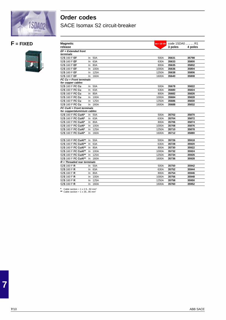
7/10
7
ABB SACE
PSIS9604
Magnetic code 1SDA0 . . . . . R1release 3 poles 4 polesEF = Extended frontterminalsS2S 160 F EF In 50A 500A 35631 35798S2S 160 F EF In 63A 630A 35633 35800S2S 160 F EF In 80A 800A 35635 35802S2S 160 F EF In 100A 1000A 35636 35804S2S 160 F EF In 125A 1250A 35638 35806S2S 160 F EF In 160A 1600A 35640 35808FC Cu = Front terminalsfor copper cablesS2S 160 F FC Cu In 50A 500A 35678 35822S2S 160 F FC Cu In 63A 630A 35680 35824S2S 160 F FC Cu In 80A 800A 35682 35826S2S 160 F FC Cu In 100A 1000A 35684 35828S2S 160 F FC Cu In 125A 1250A 35686 35830S2S 160 F FC Cu In 160A 1600A 35688 35832FC CuAl = Front terminalsfor copper/aluminium cablesS2S 160 F FC CuAl* In 50A 500A 35702 35870S2S 160 F FC CuAl* In 63A 630A 35704 35872S2S 160 F FC CuAl* In 80A 800A 35706 35874S2S 160 F FC CuAl* In 100A 1000A 35708 35876S2S 160 F FC CuAl* In 125A 1250A 35710 35878S2S 160 F FC CuAl* In 160A 1600A 35712 35880
S2S 160 F FC CuAl** In 50A 500A 35726 35918S2S 160 F FC CuAl** In 63A 630A 35728 35920S2S 160 F FC CuAl** In 80A 800A 35730 35922S2S 160 F FC CuAl** In 100A 1000A 35732 35924S2S 160 F FC CuAl** In 125A 1250A 35734 35926S2S 160 F FC CuAl** In 160A 1600A 35736 35928R = Threaded rear terminalsS2S 160 F R In 50A 500A 35750 35942S2S 160 F R In 63A 630A 35752 35944S2S 160 F R In 80A 800A 35754 35946S2S 160 F R In 100A 1000A 35756 35948S2S 160 F R In 125A 1250A 35758 35950S2S 160 F R In 160A 1600A 35760 35952
Order codesSACE Isomax S2 circuit-breaker
F = FIXED
* Cable section = 1 x 2.5...50 mm2
** Cable section = 1 x 35...95 mm2
Im = 10 Ith
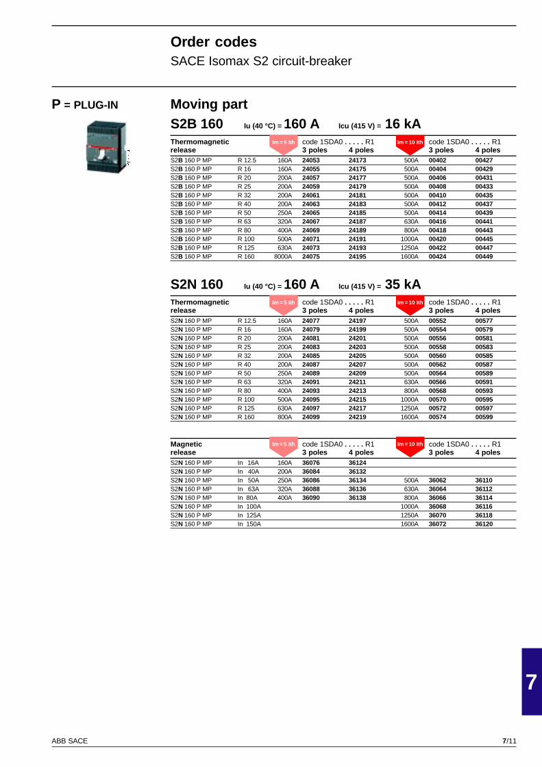
7/11
7
ABB SACE
PSIS9604
Moving partS2B 160 Iu (40 °C) = 160 A Icu (415 V) = 16 kAThermomagnetic code 1SDA0 . . . . . R1 code 1SDA0 . . . . . R1release 3 poles 4 poles 3 poles 4 polesS2B 160 P MP R 12.5 160A 24053 24173 500A 00402 00427S2B 160 P MP R 16 160A 24055 24175 500A 00404 00429S2B 160 P MP R 20 200A 24057 24177 500A 00406 00431S2B 160 P MP R 25 200A 24059 24179 500A 00408 00433S2B 160 P MP R 32 200A 24061 24181 500A 00410 00435S2B 160 P MP R 40 200A 24063 24183 500A 00412 00437S2B 160 P MP R 50 250A 24065 24185 500A 00414 00439S2B 160 P MP R 63 320A 24067 24187 630A 00416 00441S2B 160 P MP R 80 400A 24069 24189 800A 00418 00443S2B 160 P MP R 100 500A 24071 24191 1000A 00420 00445S2B 160 P MP R 125 630A 24073 24193 1250A 00422 00447S2B 160 P MP R 160 8000A 24075 24195 1600A 00424 00449
S2N 160 Iu (40 °C) = 160 A Icu (415 V) = 35 kAThermomagnetic code 1SDA0 . . . . . R1 code 1SDA0 . . . . . R1release 3 poles 4 poles 3 poles 4 polesS2N 160 P MP R 12.5 160A 24077 24197 500A 00552 00577S2N 160 P MP R 16 160A 24079 24199 500A 00554 00579S2N 160 P MP R 20 200A 24081 24201 500A 00556 00581S2N 160 P MP R 25 200A 24083 24203 500A 00558 00583S2N 160 P MP R 32 200A 24085 24205 500A 00560 00585S2N 160 P MP R 40 200A 24087 24207 500A 00562 00587S2N 160 P MP R 50 250A 24089 24209 500A 00564 00589S2N 160 P MP R 63 320A 24091 24211 630A 00566 00591S2N 160 P MP R 80 400A 24093 24213 800A 00568 00593S2N 160 P MP R 100 500A 24095 24215 1000A 00570 00595S2N 160 P MP R 125 630A 24097 24217 1250A 00572 00597S2N 160 P MP R 160 800A 24099 24219 1600A 00574 00599
Magnetic code 1SDA0 . . . . . R1 code 1SDA0 . . . . . R1release 3 poles 4 poles 3 poles 4 polesS2N 160 P MP In 16A 160A 36076 36124S2N 160 P MP In 40A 200A 36084 36132S2N 160 P MP In 50A 250A 36086 36134 500A 36062 36110S2N 160 P MP In 63A 320A 36088 36136 630A 36064 36112S2N 160 P MP In 80A 400A 36090 36138 800A 36066 36114S2N 160 P MP In 100A 1000A 36068 36116S2N 160 P MP In 125A 1250A 36070 36118S2N 160 P MP In 150A 1600A 36072 36120
P = PLUG-IN
Order codesSACE Isomax S2 circuit-breaker
Im = 5 Ith Im = 10 Ith
Im = 5 Ith Im = 10 Ith
Im = 5 Ith Im = 10 Ith
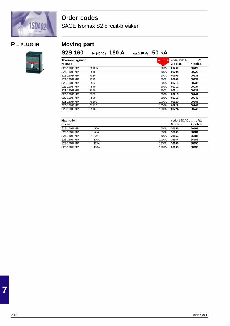
7/12
7
ABB SACE
Im = 5 Ith
PSIS9604
Moving partS2S 160 Iu (40 °C) = 160 A Icu (415 V) = 50 kAThermomagnetic code 1SDA0 . . . . . R1release 3 poles 4 polesS2S 160 P MP R 12.5 500A 00702 00727S2S 160 P MP R 16 500A 00704 00729S2S 160 P MP R 20 500A 00706 00731S2S 160 P MP R 25 500A 00708 00733S2S 160 P MP R 32 500A 00710 00735S2S 160 P MP R 40 500A 00712 00737S2S 160 P MP R 50 500A 00714 00739S2S 160 P MP R 63 630A 00716 00741S2S 160 P MP R 80 800A 00718 00743S2S 160 P MP R 100 1000A 00720 00745S2S 160 P MP R 125 1250A 00722 00747S2S 160 P MP R 160 1600A 00724 00749
Magnetic code 1SDA0 . . . . . R1release 3 poles 4 polesS2S 160 P MP In 50A 500A 36158 36182S2S 160 P MP In 63A 630A 36160 36184S2S 160 P MP In 80A 800A 36162 36186S2S 160 P MP In 100A 1000A 36164 36188S2S 160 P MP In 125A 1250A 36166 36190S2S 160 P MP In 150A 1600A 36168 36192
P = PLUG-IN
Order codesSACE Isomax S2 circuit-breaker
Im = 10 Ith

7/13
7
ABB SACE
PSIS9607
S3N 160 Iu (40 °C) = 160 A Icu (415 V) = 35 kAThermomagnetic code 1SDA0 . . . . . R1release 3 poles 4 polesF = Front terminalsS3N 160 F F R 100 300A 48539 48549S3N 160 F F R 125 375A 48540 48550S3N 160 F F R 160 I480A 48541 48551S3N 160 F F (N50%) R 160 I480A 48559
Thermomagnetic code 1SDA0 . . . . . R1 code 1SDA0 . . . . . R1release 3 poles 4 poles 3 poles 4 polesF = Front terminalsS3N 160 F F R 32 250A 13359 13383 500A 13346 13371S3N 160 F F R 50 250A 13361 13385 500A 13348 13373S3N 160 F F R 80 400A 13363 13387 800A 13350 13375S3N 160 F F R 100 500A 13365 13389 1000A 13352 13377S3N 160 F F R 125 625A 13367 13391 1250A 13354 13379S3N 160 F F R 160 800A 13369 13393 1600A 13356 13381EF = Extended frontterminalsS3N 160 F EF R 32 250A 00764 01389 500A 00752 01377S3N 160 F EF R 50 250A 00766 01391 500A 00754 01379S3N 160 F EF R 80 400A 00768 01393 800A 00756 01381S3N 160 F EF R 100 500A 00770 01395 1000A 00758 01383S3N 160 F EF R 125 625A 00772 01397 1250A 00760 01385S3N 160 F EF R 160 800A 00774 01399 1600A 00762 01387FC Cu = Front terminalsfor copper cablesS3N 160 F FC Cu R 32 250A 00914 01539 500A 00902 01527S3N 160 F FC Cu R 50 250A 00916 01541 500A 00904 01529S3N 160 F FC Cu R 80 400A 00918 01543 800A 00906 01531S3N 160 F FC Cu R 100 500A 00920 01545 1000A 00908 01533S3N 160 F FC Cu R 125 625A 00922 01547 1250A 00910 01535S3N 160 F FC Cu R 160 800A 00924 01549 1600A 00912 01537FC CuAl = Front terminalsfor copper/aluminium cablesS3N 160 F FC CuAl R 32 250A 01064 01689 500A 01052 01677S3N 160 F FC CuAl R 50 250A 01066 01691 500A 01054 01679S3N 160 F FC CuAl R 80 400A 01068 01693 800A 01056 01681S3N 160 F FC CuAl R 100 500A 01070 01695 1000A 01058 01683S3N 160 F FC CuAl R 125 625A 01072 01697 1250A 01060 01685S3N 160 F FC CuAl R 160 800A 01074 01699 1600A 01062 01687R = Threaded rear terminalsS3N 160 F R R 32 250A 01364 14243 500A 01352 14231S3N 160 F R R 50 250A 01366 14245 500A 01354 14233S3N 160 F R R 80 400A 01368 14247 800A 01356 14235S3N 160 F R R 100 500A 01370 14249 1000A 01358 14237S3N 160 F R R 125 625A 01372 14251 1250A 01360 14239S3N 160 F R R 160 800A 01374 14253 1600A 01362 14241RC = Rear terminalsfor cablesS3N 160 F RC R 32 250A 01214 01839 500A 01202 01827S3N 160 F RC R 50 250A 01216 01841 500A 01204 01829S3N 160 F RC R 80 400A 01218 01843 800A 01206 01831S3N 160 F RC R 100 500A 01220 01845 1000A 01208 01833S3N 160 F RC R 125 625A 01222 01847 1250A 01210 01835S3N 160 F RC R 160 800A 01224 01849 1600A 01212 01837R Res. Cur = Threaded rear terminals +kit of threaded rear terminalsfor residual-current releaseinstalled below the circuit-breakerS3N 160 F R Res. Cur R 32 250A 25459 500A 25447S3N 160 F R Res. Cur R 50 250A 25461 500A 25449S3N 160 F R Res. Cur R 80 400A 25463 800A 25451S3N 160 F R Res. Cur R 100 500A 25465 1000A 25454S3N 160 F R Res. Cur R 125 625A 25467 1250A 25455S3N 160 F R Res. Cur R 160 800A 25469 1600A 25457
F = FIXED
Order codesSACE Isomax S2 circuit-breaker
Im = 5 Ith Im = 10 Ith
Im = 3 Ith

7/14
7
ABB SACE
PSIS9607
Magnetic code 1SDA0 . . . . . R1 code 1SDA0 . . . . . R1release 3 poles 4 poles 3 poles 4 polesF = Front terminalsS3N 160 F F In 50A 250A 25817 25889 500A 25804 25877S3N 160 F F In 80A 400A 25819 25891 800A 25807 25879S3N 160 F F In 100A 1000A 25809 25881S3N 160 F F In 125A 625A 25823 25895 1250A 25811 25883S3N 160 F F In 160A 1600A 25813 25885EF = Extended frontterminalsS3N 160 F EF In 50A 250A 27930 29706 500A 27918 29694S3N 160 F EF In 80A 400A 27932 29708 800A 27920 29696S3N 160 F EF In 100A 1000A 27922 29698S3N 160 F EF In 125A 625A 27936 29712 1250A 27924 29700S3N 160 F EF In 160A 1600A 27926 29702FC Cu = Front terminalsfor copper cablesS3N 160 F FC Cu In 50A 250A 28074 29850 500A 28062 29838S3N 160 F FC Cu In 80A 400A 28076 29852 800A 28064 29840S3N 160 F FC Cu In 100A 1000A 28066 29842S3N 160 F FC Cu In 125A 625A 28080 29856 1250A 28068 29844S3N 160 F FC Cu In 160A 1600A 28070 29846FC CuAl = Front terminalsfor copper/aluminium cablesS3N 160 F FC CuAl In 50A 250A 28218 29994 500A 28206 29982S3N 160 F FC CuAl In 80A 400A 28220 29996 800A 28208 29984S3N 160 F FC CuAl In 100A 1000A 28210 29986S3N 160 F FC CuAl In 125A 625A 28224 30000 1250A 28212 29988S3N 160 F FC CuAl In 160A 1600A 28214 29990R = Threaded rear terminalsS3N 160 F R In 50A 250A 28506 30282 500A 28494 30270S3N 160 F R In 80A 400A 28508 30284 800A 28496 30272S3N 160 F R In 100A 1000A 28498 30274S3N 160 F R In 125A 625A 28512 30288 1250A 28500 30276S3N 160 F R In 160A 1600A 28502 30278RC = Rear terminalsfor cablesS3N 160 F RC In 50A 250A 28362 30138 500A 28350 30126S3N 160 F RC In 80A 400A 28364 30140 800A 28352 30128S3N 160 F RC In 100A 1000A 28354 30130S3N 160 F RC In 125A 625A 28368 30144 1250A 28356 30132S3N 160 F RC In 160A 1600A 28358 30134
Order codesSACE Isomax S2 circuit-breaker
F = FIXED Im = 5 Ith Im = 10 Ith
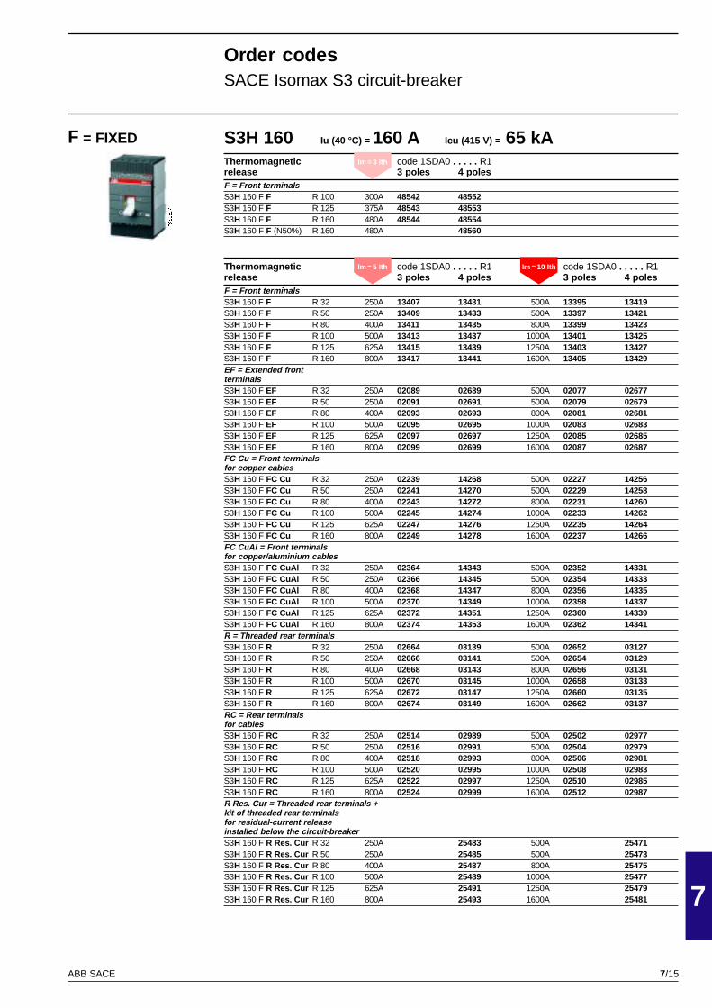
7/15
7
ABB SACE
PSIS9607
S3H 160 Iu (40 °C) = 160 A Icu (415 V) = 65 kAThermomagnetic code 1SDA0 . . . . . R1release 3 poles 4 polesF = Front terminalsS3H 160 F F R 100 300A 48542 48552S3H 160 F F R 125 375A 48543 48553S3H 160 F F R 160 480A 48544 48554S3H 160 F F (N50%) R 160 480A 48560
Thermomagnetic code 1SDA0 . . . . . R1 code 1SDA0 . . . . . R1release 3 poles 4 poles 3 poles 4 polesF = Front terminalsS3H 160 F F R 32 250A 13407 13431 500A 13395 13419S3H 160 F F R 50 250A 13409 13433 500A 13397 13421S3H 160 F F R 80 400A 13411 13435 800A 13399 13423S3H 160 F F R 100 500A 13413 13437 1000A 13401 13425S3H 160 F F R 125 625A 13415 13439 1250A 13403 13427S3H 160 F F R 160 800A 13417 13441 1600A 13405 13429EF = Extended frontterminalsS3H 160 F EF R 32 250A 02089 02689 500A 02077 02677S3H 160 F EF R 50 250A 02091 02691 500A 02079 02679S3H 160 F EF R 80 400A 02093 02693 800A 02081 02681S3H 160 F EF R 100 500A 02095 02695 1000A 02083 02683S3H 160 F EF R 125 625A 02097 02697 1250A 02085 02685S3H 160 F EF R 160 800A 02099 02699 1600A 02087 02687FC Cu = Front terminalsfor copper cablesS3H 160 F FC Cu R 32 250A 02239 14268 500A 02227 14256S3H 160 F FC Cu R 50 250A 02241 14270 500A 02229 14258S3H 160 F FC Cu R 80 400A 02243 14272 800A 02231 14260S3H 160 F FC Cu R 100 500A 02245 14274 1000A 02233 14262S3H 160 F FC Cu R 125 625A 02247 14276 1250A 02235 14264S3H 160 F FC Cu R 160 800A 02249 14278 1600A 02237 14266FC CuAl = Front terminalsfor copper/aluminium cablesS3H 160 F FC CuAl R 32 250A 02364 14343 500A 02352 14331S3H 160 F FC CuAl R 50 250A 02366 14345 500A 02354 14333S3H 160 F FC CuAl R 80 400A 02368 14347 800A 02356 14335S3H 160 F FC CuAl R 100 500A 02370 14349 1000A 02358 14337S3H 160 F FC CuAl R 125 625A 02372 14351 1250A 02360 14339S3H 160 F FC CuAl R 160 800A 02374 14353 1600A 02362 14341R = Threaded rear terminalsS3H 160 F R R 32 250A 02664 03139 500A 02652 03127S3H 160 F R R 50 250A 02666 03141 500A 02654 03129S3H 160 F R R 80 400A 02668 03143 800A 02656 03131S3H 160 F R R 100 500A 02670 03145 1000A 02658 03133S3H 160 F R R 125 625A 02672 03147 1250A 02660 03135S3H 160 F R R 160 800A 02674 03149 1600A 02662 03137RC = Rear terminalsfor cablesS3H 160 F RC R 32 250A 02514 02989 500A 02502 02977S3H 160 F RC R 50 250A 02516 02991 500A 02504 02979S3H 160 F RC R 80 400A 02518 02993 800A 02506 02981S3H 160 F RC R 100 500A 02520 02995 1000A 02508 02983S3H 160 F RC R 125 625A 02522 02997 1250A 02510 02985S3H 160 F RC R 160 800A 02524 02999 1600A 02512 02987R Res. Cur = Threaded rear terminals +kit of threaded rear terminalsfor residual-current releaseinstalled below the circuit-breakerS3H 160 F R Res. Cur R 32 250A 25483 500A 25471S3H 160 F R Res. Cur R 50 250A 25485 500A 25473S3H 160 F R Res. Cur R 80 400A 25487 800A 25475S3H 160 F R Res. Cur R 100 500A 25489 1000A 25477S3H 160 F R Res. Cur R 125 625A 25491 1250A 25479S3H 160 F R Res. Cur R 160 800A 25493 1600A 25481
Order codesSACE Isomax S3 circuit-breaker
F = FIXED
Im = 5 Ith Im = 10 Ith
Im = 3 Ith

7/16
7
ABB SACE
PSIS9607
Magnetic code 1SDA0 . . . . . R1 code 1SDA0 . . . . . R1release 3 poles 4 poles 3 poles 4 polesF = Front terminalsS3H 160 F F In 50A 250A 25841 25913 500A 25829 25901S3H 160 F F In 80A 400A 25843 25915 800A 25831 25903S3H 160 F F In 100A 1000A 25833 25905S3H 160 F F In 125A 625A 25847 25919 1250A 25835 25907S3H 160 F F In 160A 1600A 25837 25909EF = Extended frontterminalsS3H 160 F EF In 50A 250A 28530 30306 500A 28518 30294S3H 160 F EF In 80A 400A 28532 30308 800A 28520 30296S3H 160 F EF In 100A 1000A 28522 30298S3H 160 F EF In 125A 625A 28536 30312 1250A 28524 30300S3H 160 F EF In 160A 1600A 28526 30302FC Cu = Front terminalsfor copper cablesS3H 160 F FC Cu In 50A 250A 28674 30450 500A 28662 30438S3H 160 F FC Cu In 80A 400A 28676 30452 800A 28664 30440S3H 160 F FC Cu In 100A 1000A 28666 30442S3H 160 F FC Cu In 125A 625A 28680 30456 1250A 28668 30444S3H 160 F FC Cu In 160A 1600A 28670 30446FC CuAl = Front terminalsfor copper/aluminium cablesS3H 160 F FC CuAl In 50A 250A 28818 30594 500A 28806 30582S3H 160 F FC CuAl In 80A 400A 28820 30596 800A 28808 30584S3H 160 F FC CuAl In 100A 1000A 28810 30586S3H 160 F FC CuAl In 125A 625A 28824 30600 1250A 28812 30588S3H 160 F FC CuAl In 160A 1600A 28814 30590R = Threaded rear terminalsS3H 160 F R In 50A 250A 29106 30882 500A 29094 30870S3H 160 F R In 80A 400A 29108 30884 800A 29096 30872S3H 160 F R In 100A 1000A 29098 30874S3H 160 F R In 125A 625A 29112 30888 1250A 29100 30876S3H 160 F R In 160A 1600A 29102 30878RC = Rear terminalsfor cablesS3H 160 F RC In 50A 250A 28962 30738 500A 28950 30726S3H 160 F RC In 80A 400A 28964 30740 800A 28952 30728S3H 160 F RC In 100A 1000A 28954 30730S3H 160 F RC In 125A 625A 28968 30744 1250A 28956 30732S3H 160 F RC In 160A 1600A 28958 30734
Order codesSACE Isomax S3 circuit-breaker
F = FIXED Im = 5 Ith Im = 10 Ith

7/17
7
ABB SACE
PSIS9607
S3L 160 Iu (40 °C) = 160 A Icu (415 V) = 85 kAThermomagnetic code 1SDA0 . . . . . R1 code 1SDA0 . . . . . R1release 3 poles 4 poles 3 poles 4 polesF = Front terminalsS3L 160 F F R 32 250A 13455 13479 500A 13443 13467S3L 160 F F R 50 250A 13457 13481 500A 13445 13469S3L 160 F F R 80 400A 13459 13483 800A 13447 13471S3L 160 F F R 100 500A 13461 13485 1000A 13449 13473S3L 160 F F R 125 625A 13463 13487 1250A 13451 13475S3L 160 F F R 160 800A 13465 13489 1600A 13453 13477EF = Extended frontterminalsS3L 160 F EF R 32 250A 03264 03864 500A 03252 03852S3L 160 F EF R 50 250A 03266 03866 500A 03254 03854S3L 160 F EF R 80 400A 14486 14511 800A 03256 03856S3L 160 F EF R 100 500A 03269 03869 1000A 03258 03858S3L 160 F EF R 125 625A 03271 03871 1250A 03260 03860S3L 160 F EF R 160 800A 03273 03873 1600A 03262 03862FC Cu = Front terminalsfor copper cablesS3L 160 F FC Cu R 32 250A 03408 04008 500A 03396 03996S3L 160 F FC Cu R 50 250A 03410 04010 500A 03398 03998S3L 160 F FC Cu R 80 400A 14492 14517 800A 03400 04000S3L 160 F FC Cu R 100 500A 03413 04013 1000A 03402 04002S3L 160 F FC Cu R 125 625A 03415 04015 1250A 03404 04004S3L 160 F FC Cu R 160 800A 03417 04017 1600A 03406 04006FC CuAl = Front terminalsfor copper/aluminium cablesS3L 160 F FC CuAl R 32 250A 03552 04152 500A 03540 04140S3L 160 F FC CuAl R 50 250A 03554 04154 500A 03542 04142S3L 160 F FC CuAl R 80 400A 14498 14523 800A 03544 04144S3L 160 F FC CuAl R 100 500A 03557 04157 1000A 03546 04146S3L 160 F FC CuAl R 125 625A 03559 04159 1250A 03548 04148S3L 160 F FC CuAl R 160 800A 03561 04161 1600A 03550 04150R = Threaded rear terminalsS3L 160 F R R 32 250A 03840 04440 500A 03828 04428S3L 160 F R R 50 250A 03842 04442 500A 03830 04430S3L 160 F R R 80 400A 14510 14535 800A 03832 04432S3L 160 F R R 100 500A 03845 04445 1000A 03834 04434S3L 160 F R R 125 625A 03847 04447 1250A 03836 04436S3L 160 F R R 160 800A 03849 04449 1600A 03838 04438RC = Rear terminalsfor cablesS3L 160 F RC R 32 250A 03696 04296 500A 03684 04284S3L 160 F RC R 50 250A 03698 04298 500A 03686 04286S3L 160 F RC R 80 400A 14504 14529 800A 03688 04288S3L 160 F RC R 100 500A 03701 04301 1000A 03690 04290S3L 160 F RC R 125 625A 03703 04303 1250A 03692 04292S3L 160 F RC R 160 800A 03705 04305 1600A 03694 04294R Res. Cur = Threaded rear terminals +kit of threaded rear terminalsfor residual-current releaseinstalled below the circuit-breakerS3L 160 F R Res. Cur R 32 250A 25507 500A 25495S3L 160 F R Res. Cur R 50 250A 25509 500A 25497S3L 160 F R Res. Cur R 80 400A 25511 800A 25499S3L 160 F R Res. Cur R 100 500A 25513 1000A 25501S3L 160 F R Res. Cur R 125 625A 25515 1250A 25503S3L 160 F R Res. Cur R 160 800A 25517 1600A 25505
Order codesSACE Isomax S3 circuit-breaker
F = FIXED
Im = 5 Ith Im = 10 Ith
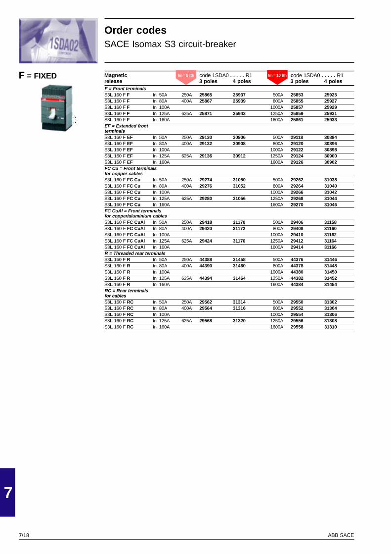
7/18
7
ABB SACE
PSIS9607
Magnetic code 1SDA0 . . . . . R1 code 1SDA0 . . . . . R1release 3 poles 4 poles 3 poles 4 polesF = Front terminalsS3L 160 F F In 50A 250A 25865 25937 500A 25853 25925S3L 160 F F In 80A 400A 25867 25939 800A 25855 25927S3L 160 F F In 100A 1000A 25857 25929S3L 160 F F In 125A 625A 25871 25943 1250A 25859 25931S3L 160 F F In 160A 1600A 25861 25933EF = Extended frontterminalsS3L 160 F EF In 50A 250A 29130 30906 500A 29118 30894S3L 160 F EF In 80A 400A 29132 30908 800A 29120 30896S3L 160 F EF In 100A 1000A 29122 30898S3L 160 F EF In 125A 625A 29136 30912 1250A 29124 30900S3L 160 F EF In 160A 1600A 29126 30902FC Cu = Front terminalsfor copper cablesS3L 160 F FC Cu In 50A 250A 29274 31050 500A 29262 31038S3L 160 F FC Cu In 80A 400A 29276 31052 800A 29264 31040S3L 160 F FC Cu In 100A 1000A 29266 31042S3L 160 F FC Cu In 125A 625A 29280 31056 1250A 29268 31044S3L 160 F FC Cu In 160A 1600A 29270 31046FC CuAl = Front terminalsfor copper/aluminium cablesS3L 160 F FC CuAl In 50A 250A 29418 31170 500A 29406 31158S3L 160 F FC CuAl In 80A 400A 29420 31172 800A 29408 31160S3L 160 F FC CuAl In 100A 1000A 29410 31162S3L 160 F FC CuAl In 125A 625A 29424 31176 1250A 29412 31164S3L 160 F FC CuAl In 160A 1600A 29414 31166R = Threaded rear terminalsS3L 160 F R In 50A 250A 44388 31458 500A 44376 31446S3L 160 F R In 80A 400A 44390 31460 800A 44378 31448S3L 160 F R In 100A 1000A 44380 31450S3L 160 F R In 125A 625A 44394 31464 1250A 44382 31452S3L 160 F R In 160A 1600A 44384 31454RC = Rear terminalsfor cablesS3L 160 F RC In 50A 250A 29562 31314 500A 29550 31302S3L 160 F RC In 80A 400A 29564 31316 800A 29552 31304S3L 160 F RC In 100A 1000A 29554 31306S3L 160 F RC In 125A 625A 29568 31320 1250A 29556 31308S3L 160 F RC In 160A 1600A 29558 31310
Order codesSACE Isomax S3 circuit-breaker
F = FIXED Im = 5 Ith Im = 10 Ith
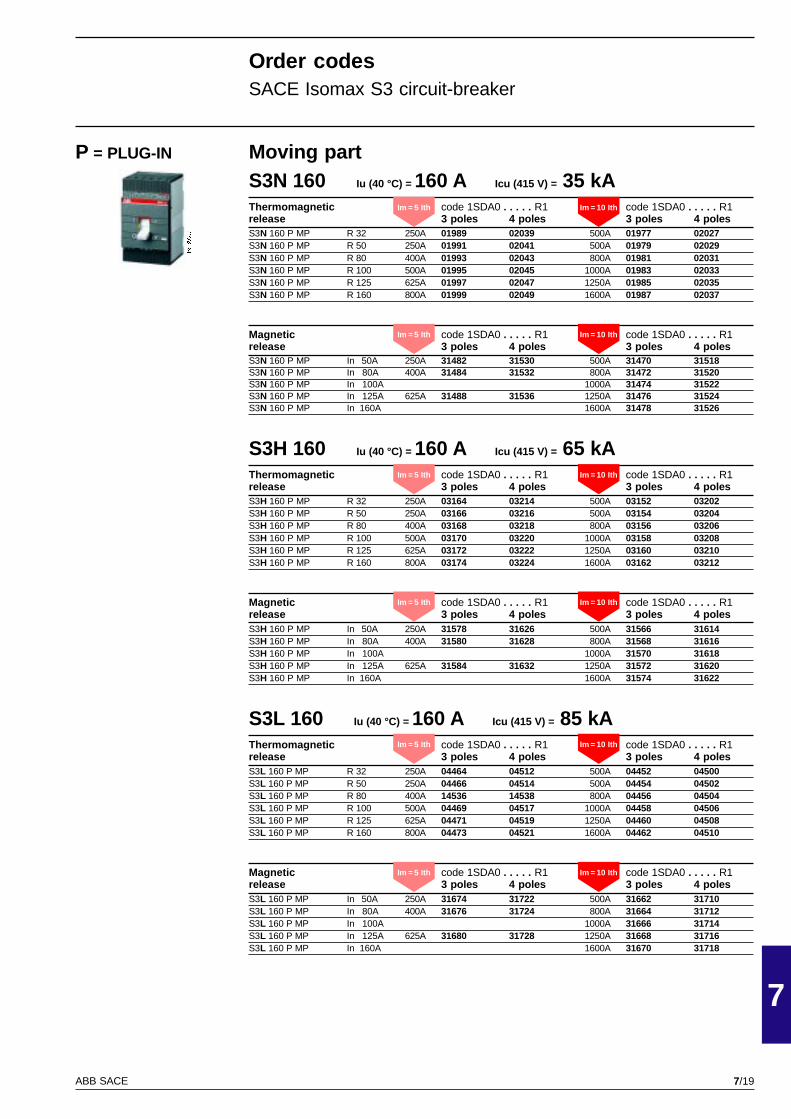
7/19
7
ABB SACE
PSIS9607
Moving partS3N 160 Iu (40 °C) = 160 A Icu (415 V) = 35 kAThermomagnetic code 1SDA0 . . . . . R1 code 1SDA0 . . . . . R1release 3 poles 4 poles 3 poles 4 polesS3N 160 P MP R 32 250A 01989 02039 500A 01977 02027S3N 160 P MP R 50 250A 01991 02041 500A 01979 02029S3N 160 P MP R 80 400A 01993 02043 800A 01981 02031S3N 160 P MP R 100 500A 01995 02045 1000A 01983 02033S3N 160 P MP R 125 625A 01997 02047 1250A 01985 02035S3N 160 P MP R 160 800A 01999 02049 1600A 01987 02037
Magnetic code 1SDA0 . . . . . R1 code 1SDA0 . . . . . R1release 3 poles 4 poles 3 poles 4 polesS3N 160 P MP In 50A 250A 31482 31530 500A 31470 31518S3N 160 P MP In 80A 400A 31484 31532 800A 31472 31520S3N 160 P MP In 100A 1000A 31474 31522S3N 160 P MP In 125A 625A 31488 31536 1250A 31476 31524S3N 160 P MP In 160A 1600A 31478 31526
S3H 160 Iu (40 °C) = 160 A Icu (415 V) = 65 kAThermomagnetic code 1SDA0 . . . . . R1 code 1SDA0 . . . . . R1release 3 poles 4 poles 3 poles 4 polesS3H 160 P MP R 32 250A 03164 03214 500A 03152 03202S3H 160 P MP R 50 250A 03166 03216 500A 03154 03204S3H 160 P MP R 80 400A 03168 03218 800A 03156 03206S3H 160 P MP R 100 500A 03170 03220 1000A 03158 03208S3H 160 P MP R 125 625A 03172 03222 1250A 03160 03210S3H 160 P MP R 160 800A 03174 03224 1600A 03162 03212
Magnetic code 1SDA0 . . . . . R1 code 1SDA0 . . . . . R1release 3 poles 4 poles 3 poles 4 polesS3H 160 P MP In 50A 250A 31578 31626 500A 31566 31614S3H 160 P MP In 80A 400A 31580 31628 800A 31568 31616S3H 160 P MP In 100A 1000A 31570 31618S3H 160 P MP In 125A 625A 31584 31632 1250A 31572 31620S3H 160 P MP In 160A 1600A 31574 31622
S3L 160 Iu (40 °C) = 160 A Icu (415 V) = 85 kAThermomagnetic code 1SDA0 . . . . . R1 code 1SDA0 . . . . . R1release 3 poles 4 poles 3 poles 4 polesS3L 160 P MP R 32 250A 04464 04512 500A 04452 04500S3L 160 P MP R 50 250A 04466 04514 500A 04454 04502S3L 160 P MP R 80 400A 14536 14538 800A 04456 04504S3L 160 P MP R 100 500A 04469 04517 1000A 04458 04506S3L 160 P MP R 125 625A 04471 04519 1250A 04460 04508S3L 160 P MP R 160 800A 04473 04521 1600A 04462 04510
Magnetic code 1SDA0 . . . . . R1 code 1SDA0 . . . . . R1release 3 poles 4 poles 3 poles 4 polesS3L 160 P MP In 50A 250A 31674 31722 500A 31662 31710S3L 160 P MP In 80A 400A 31676 31724 800A 31664 31712S3L 160 P MP In 100A 1000A 31666 31714S3L 160 P MP In 125A 625A 31680 31728 1250A 31668 31716S3L 160 P MP In 160A 1600A 31670 31718
P = PLUG-IN
Order codesSACE Isomax S3 circuit-breaker
Im = 5 Ith Im = 10 Ith
Im = 5 Ith Im = 10 Ith
Im = 5 Ith Im = 10 Ith
Im = 5 Ith Im = 10 Ith
Im = 5 Ith Im = 10 Ith
Im = 5 Ith Im = 10 Ith
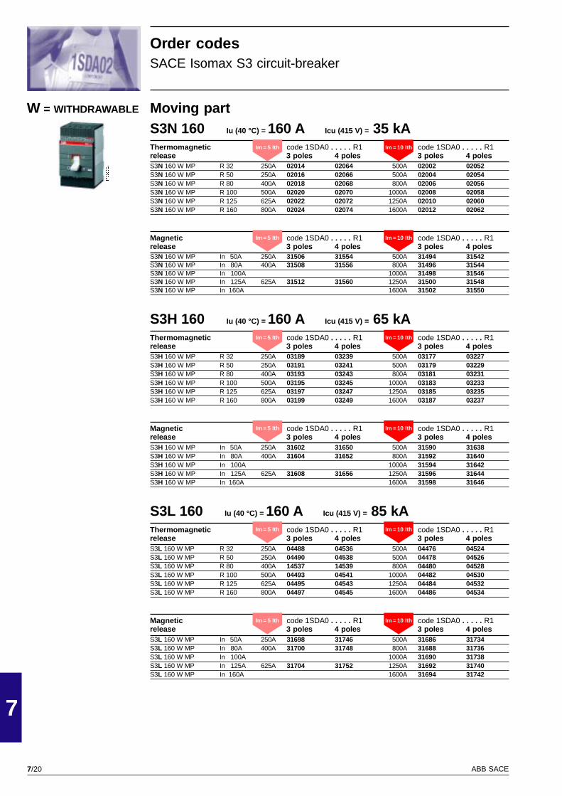
7/20
7
ABB SACE
PSIS9607
Moving partS3N 160 Iu (40 °C) = 160 A Icu (415 V) = 35 kAThermomagnetic code 1SDA0 . . . . . R1 code 1SDA0 . . . . . R1release 3 poles 4 poles 3 poles 4 polesS3N 160 W MP R 32 250A 02014 02064 500A 02002 02052S3N 160 W MP R 50 250A 02016 02066 500A 02004 02054S3N 160 W MP R 80 400A 02018 02068 800A 02006 02056S3N 160 W MP R 100 500A 02020 02070 1000A 02008 02058S3N 160 W MP R 125 625A 02022 02072 1250A 02010 02060S3N 160 W MP R 160 800A 02024 02074 1600A 02012 02062
Magnetic code 1SDA0 . . . . . R1 code 1SDA0 . . . . . R1release 3 poles 4 poles 3 poles 4 polesS3N 160 W MP In 50A 250A 31506 31554 500A 31494 31542S3N 160 W MP In 80A 400A 31508 31556 800A 31496 31544S3N 160 W MP In 100A 1000A 31498 31546S3N 160 W MP In 125A 625A 31512 31560 1250A 31500 31548S3N 160 W MP In 160A 1600A 31502 31550
S3H 160 Iu (40 °C) = 160 A Icu (415 V) = 65 kAThermomagnetic code 1SDA0 . . . . . R1 code 1SDA0 . . . . . R1release 3 poles 4 poles 3 poles 4 polesS3H 160 W MP R 32 250A 03189 03239 500A 03177 03227S3H 160 W MP R 50 250A 03191 03241 500A 03179 03229S3H 160 W MP R 80 400A 03193 03243 800A 03181 03231S3H 160 W MP R 100 500A 03195 03245 1000A 03183 03233S3H 160 W MP R 125 625A 03197 03247 1250A 03185 03235S3H 160 W MP R 160 800A 03199 03249 1600A 03187 03237
Magnetic code 1SDA0 . . . . . R1 code 1SDA0 . . . . . R1release 3 poles 4 poles 3 poles 4 polesS3H 160 W MP In 50A 250A 31602 31650 500A 31590 31638S3H 160 W MP In 80A 400A 31604 31652 800A 31592 31640S3H 160 W MP In 100A 1000A 31594 31642S3H 160 W MP In 125A 625A 31608 31656 1250A 31596 31644S3H 160 W MP In 160A 1600A 31598 31646
S3L 160 Iu (40 °C) = 160 A Icu (415 V) = 85 kAThermomagnetic code 1SDA0 . . . . . R1 code 1SDA0 . . . . . R1release 3 poles 4 poles 3 poles 4 polesS3L 160 W MP R 32 250A 04488 04536 500A 04476 04524S3L 160 W MP R 50 250A 04490 04538 500A 04478 04526S3L 160 W MP R 80 400A 14537 14539 800A 04480 04528S3L 160 W MP R 100 500A 04493 04541 1000A 04482 04530S3L 160 W MP R 125 625A 04495 04543 1250A 04484 04532S3L 160 W MP R 160 800A 04497 04545 1600A 04486 04534
Magnetic code 1SDA0 . . . . . R1 code 1SDA0 . . . . . R1release 3 poles 4 poles 3 poles 4 polesS3L 160 W MP In 50A 250A 31698 31746 500A 31686 31734S3L 160 W MP In 80A 400A 31700 31748 800A 31688 31736S3L 160 W MP In 100A 1000A 31690 31738S3L 160 W MP In 125A 625A 31704 31752 1250A 31692 31740S3L 160 W MP In 160A 1600A 31694 31742
W = WITHDRAWABLE
Order codesSACE Isomax S3 circuit-breaker
Im = 5 Ith Im = 10 Ith
Im = 5 Ith Im = 10 Ith
Im = 5 Ith Im = 10 Ith
Im = 5 Ith Im = 10 Ith
Im = 5 Ith Im = 10 Ith
Im = 5 Ith Im = 10 Ith
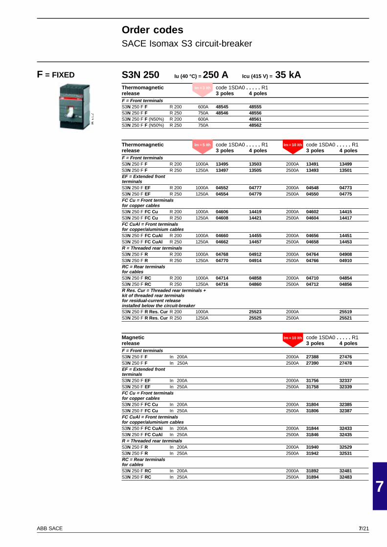
7/21
7
ABB SACE
PSIS9607
S3N 250 Iu (40 °C) = 250 A Icu (415 V) = 35 kAThermomagnetic code 1SDA0 . . . . . R1release 3 poles 4 polesF = Front terminalsS3N 250 F F R 200 600A 48545 48555S3N 250 F F R 250 750A 48546 48556S3N 250 F F (N50%) R 200 600A 48561S3N 250 F F (N50%) R 250 750A 48562
Thermomagnetic code 1SDA0 . . . . . R1 code 1SDA0 . . . . . R1release 3 poles 4 poles 3 poles 4 polesF = Front terminalsS3N 250 F F R 200 1000A 13495 13503 2000A 13491 13499S3N 250 F F R 250 1250A 13497 13505 2500A 13493 13501EF = Extended frontterminalsS3N 250 F EF R 200 1000A 04552 04777 2000A 04548 04773S3N 250 F EF R 250 1250A 04554 04779 2500A 04550 04775FC Cu = Front terminalsfor copper cablesS3N 250 F FC Cu R 200 1000A 04606 14419 2000A 04602 14415S3N 250 F FC Cu R 250 1250A 04608 14421 2500A 04604 14417FC CuAl = Front terminalsfor copper/aluminium cablesS3N 250 F FC CuAl R 200 1000A 04660 14455 2000A 04656 14451S3N 250 F FC CuAl R 250 1250A 04662 14457 2500A 04658 14453R = Threaded rear terminalsS3N 250 F R R 200 1000A 04768 04912 2000A 04764 04908S3N 250 F R R 250 1250A 04770 04914 2500A 04766 04910RC = Rear terminalsfor cablesS3N 250 F RC R 200 1000A 04714 04858 2000A 04710 04854S3N 250 F RC R 250 1250A 04716 04860 2500A 04712 04856R Res. Cur = Threaded rear terminals +kit of threaded rear terminalsfor residual-current releaseinstalled below the circuit-breakerS3N 250 F R Res. Cur R 200 1000A 25523 2000A 25519S3N 250 F R Res. Cur R 250 1250A 25525 2500A 25521
Magnetic code 1SDA0 . . . . . R1release 3 poles 4 polesF = Front terminalsS3N 250 F F In 200A 2000A 27388 27476S3N 250 F F In 250A 2500A 27390 27478EF = Extended frontterminalsS3N 250 F EF In 200A 2000A 31756 32337S3N 250 F EF In 250A 2500A 31758 32339FC Cu = Front terminalsfor copper cablesS3N 250 F FC Cu In 200A 2000A 31804 32385S3N 250 F FC Cu In 250A 2500A 31806 32387FC CuAl = Front terminalsfor copper/aluminium cablesS3N 250 F FC CuAl In 200A 2000A 31844 32433S3N 250 F FC CuAl In 250A 2500A 31846 32435R = Threaded rear terminalsS3N 250 F R In 200A 2000A 31940 32529S3N 250 F R In 250A 2500A 31942 32531RC = Rear terminalsfor cablesS3N 250 F RC In 200A 2000A 31892 32481S3N 250 F RC In 250A 2500A 31894 32483
Order codesSACE Isomax S3 circuit-breaker
F = FIXED
Im = 5 Ith Im = 10 Ith
Im = 3 Ith
Im = 10 Ith
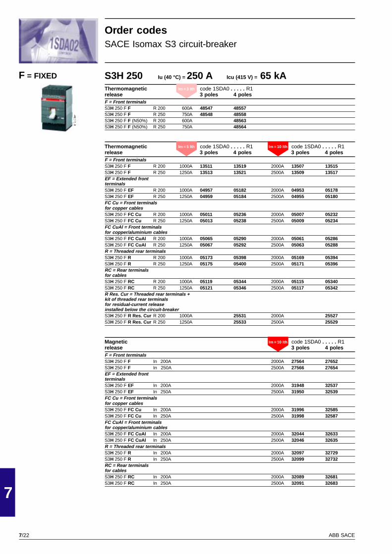
7/22
7
ABB SACE
PSIS9607
S3H 250 Iu (40 °C) = 250 A Icu (415 V) = 65 kAThermomagnetic code 1SDA0 . . . . . R1release 3 poles 4 polesF = Front terminalsS3H 250 F F R 200 600A 48547 48557S3H 250 F F R 250 750A 48548 48558S3H 250 F F (N50%) R 200 600A 48563S3H 250 F F (N50%) R 250 750A 48564
Thermomagnetic code 1SDA0 . . . . . R1 code 1SDA0 . . . . . R1release 3 poles 4 poles 3 poles 4 polesF = Front terminalsS3H 250 F F R 200 1000A 13511 13519 2000A 13507 13515S3H 250 F F R 250 1250A 13513 13521 2500A 13509 13517EF = Extended frontterminalsS3H 250 F EF R 200 1000A 04957 05182 2000A 04953 05178S3H 250 F EF R 250 1250A 04959 05184 2500A 04955 05180FC Cu = Front terminalsfor copper cablesS3H 250 F FC Cu R 200 1000A 05011 05236 2000A 05007 05232S3H 250 F FC Cu R 250 1250A 05013 05238 2500A 05009 05234FC CuAl = Front terminalsfor copper/aluminium cablesS3H 250 F FC CuAl R 200 1000A 05065 05290 2000A 05061 05286S3H 250 F FC CuAl R 250 1250A 05067 05292 2500A 05063 05288R = Threaded rear terminalsS3H 250 F R R 200 1000A 05173 05398 2000A 05169 05394S3H 250 F R R 250 1250A 05175 05400 2500A 05171 05396RC = Rear terminalsfor cablesS3H 250 F RC R 200 1000A 05119 05344 2000A 05115 05340S3H 250 F RC R 250 1250A 05121 05346 2500A 05117 05342R Res. Cur = Threaded rear terminals +kit of threaded rear terminalsfor residual-current releaseinstalled below the circuit-breakerS3H 250 F R Res. Cur R 200 1000A 25531 2000A 25527S3H 250 F R Res. Cur R 250 1250A 25533 2500A 25529
Magnetic code 1SDA0 . . . . . R1release 3 poles 4 polesF = Front terminalsS3H 250 F F In 200A 2000A 27564 27652S3H 250 F F In 250A 2500A 27566 27654EF = Extended frontterminalsS3H 250 F EF In 200A 2000A 31948 32537S3H 250 F EF In 250A 2500A 31950 32539FC Cu = Front terminalsfor copper cablesS3H 250 F FC Cu In 200A 2000A 31996 32585S3H 250 F FC Cu In 250A 2500A 31998 32587FC CuAl = Front terminalsfor copper/aluminium cablesS3H 250 F FC CuAl In 200A 2000A 32044 32633S3H 250 F FC CuAl In 250A 2500A 32046 32635R = Threaded rear terminalsS3H 250 F R In 200A 2000A 32097 32729S3H 250 F R In 250A 2500A 32099 32732RC = Rear terminalsfor cablesS3H 250 F RC In 200A 2000A 32089 32681S3H 250 F RC In 250A 2500A 32091 32683
Order codesSACE Isomax S3 circuit-breaker
F = FIXED
Im = 3 Ith
Im = 5 Ith Im = 10 Ith
Im = 10 Ith
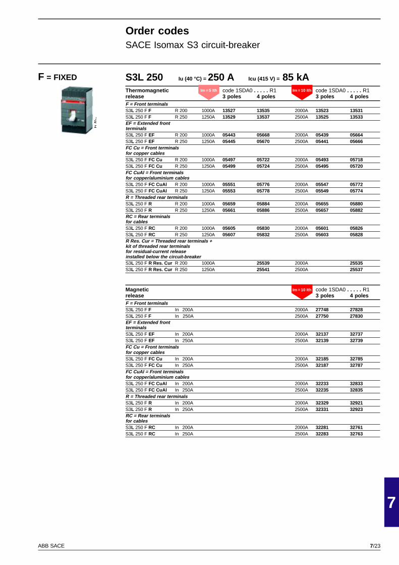
7/23
7
ABB SACE
PSIS9607
S3L 250 Iu (40 °C) = 250 A Icu (415 V) = 85 kAThermomagnetic code 1SDA0 . . . . . R1 code 1SDA0 . . . . . R1release 3 poles 4 poles 3 poles 4 polesF = Front terminalsS3L 250 F F R 200 1000A 13527 13535 2000A 13523 13531S3L 250 F F R 250 1250A 13529 13537 2500A 13525 13533EF = Extended frontterminalsS3L 250 F EF R 200 1000A 05443 05668 2000A 05439 05664S3L 250 F EF R 250 1250A 05445 05670 2500A 05441 05666FC Cu = Front terminalsfor copper cablesS3L 250 F FC Cu R 200 1000A 05497 05722 2000A 05493 05718S3L 250 F FC Cu R 250 1250A 05499 05724 2500A 05495 05720FC CuAl = Front terminalsfor copper/aluminium cablesS3L 250 F FC CuAl R 200 1000A 05551 05776 2000A 05547 05772S3L 250 F FC CuAl R 250 1250A 05553 05778 2500A 05549 05774R = Threaded rear terminalsS3L 250 F R R 200 1000A 05659 05884 2000A 05655 05880S3L 250 F R R 250 1250A 05661 05886 2500A 05657 05882RC = Rear terminalsfor cablesS3L 250 F RC R 200 1000A 05605 05830 2000A 05601 05826S3L 250 F RC R 250 1250A 05607 05832 2500A 05603 05828R Res. Cur = Threaded rear terminals +kit of threaded rear terminalsfor residual-current releaseinstalled below the circuit-breakerS3L 250 F R Res. Cur R 200 1000A 25539 2000A 25535S3L 250 F R Res. Cur R 250 1250A 25541 2500A 25537
Magnetic code 1SDA0 . . . . . R1release 3 poles 4 polesF = Front terminalsS3L 250 F F In 200A 2000A 27748 27828S3L 250 F F In 250A 2500A 27750 27830EF = Extended frontterminalsS3L 250 F EF In 200A 2000A 32137 32737S3L 250 F EF In 250A 2500A 32139 32739FC Cu = Front terminalsfor copper cablesS3L 250 F FC Cu In 200A 2000A 32185 32785S3L 250 F FC Cu In 250A 2500A 32187 32787FC CuAl = Front terminalsfor copper/aluminium cablesS3L 250 F FC CuAl In 200A 2000A 32233 32833S3L 250 F FC CuAl In 250A 2500A 32235 32835R = Threaded rear terminalsS3L 250 F R In 200A 2000A 32329 32921S3L 250 F R In 250A 2500A 32331 32923RC = Rear terminalsfor cablesS3L 250 F RC In 200A 2000A 32281 32761S3L 250 F RC In 250A 2500A 32283 32763
Order codesSACE Isomax S3 circuit-breaker
F = FIXEDIm = 5 Ith Im = 10 Ith
Im = 10 Ith
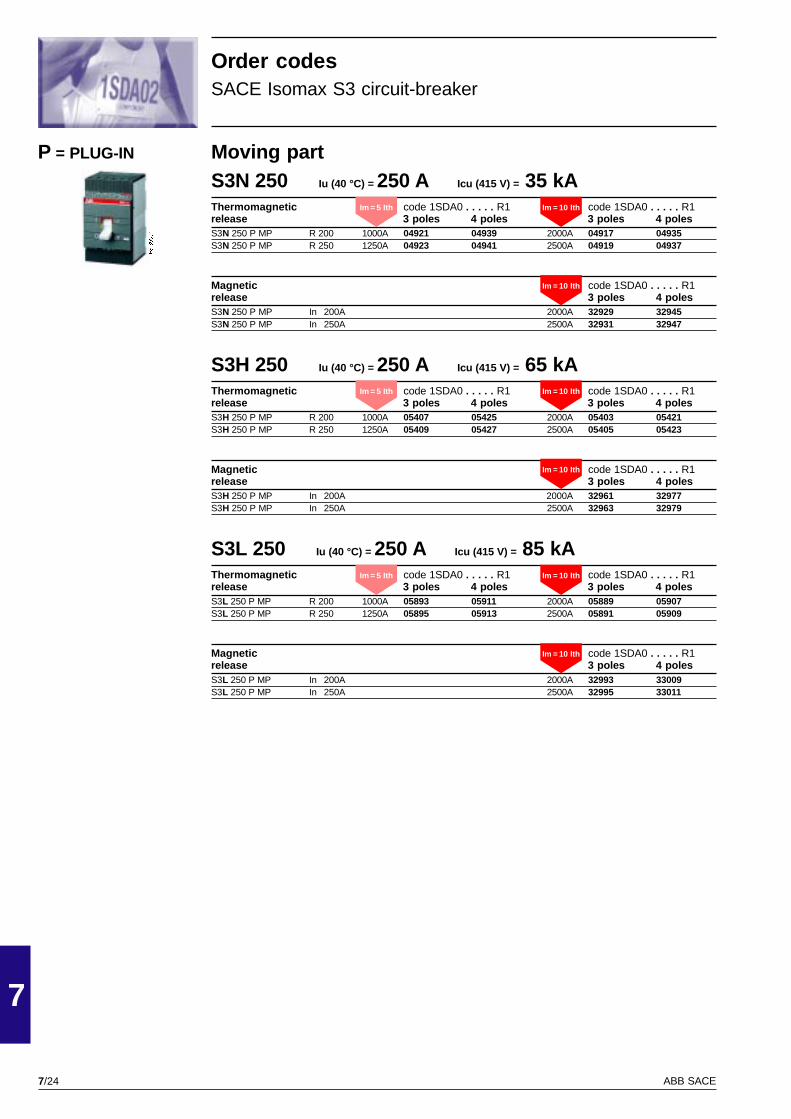
7/24
7
ABB SACE
PSIS9607
Moving partS3N 250 Iu (40 °C) = 250 A Icu (415 V) = 35 kAThermomagnetic code 1SDA0 . . . . . R1 code 1SDA0 . . . . . R1release 3 poles 4 poles 3 poles 4 polesS3N 250 P MP R 200 1000A 04921 04939 2000A 04917 04935S3N 250 P MP R 250 1250A 04923 04941 2500A 04919 04937
Magnetic code 1SDA0 . . . . . R1release 3 poles 4 polesS3N 250 P MP In 200A 2000A 32929 32945S3N 250 P MP In 250A 2500A 32931 32947
S3H 250 Iu (40 °C) = 250 A Icu (415 V) = 65 kAThermomagnetic code 1SDA0 . . . . . R1 code 1SDA0 . . . . . R1release 3 poles 4 poles 3 poles 4 polesS3H 250 P MP R 200 1000A 05407 05425 2000A 05403 05421S3H 250 P MP R 250 1250A 05409 05427 2500A 05405 05423
Magnetic code 1SDA0 . . . . . R1release 3 poles 4 polesS3H 250 P MP In 200A 2000A 32961 32977S3H 250 P MP In 250A 2500A 32963 32979
S3L 250 Iu (40 °C) = 250 A Icu (415 V) = 85 kAThermomagnetic code 1SDA0 . . . . . R1 code 1SDA0 . . . . . R1release 3 poles 4 poles 3 poles 4 polesS3L 250 P MP R 200 1000A 05893 05911 2000A 05889 05907S3L 250 P MP R 250 1250A 05895 05913 2500A 05891 05909
Magnetic code 1SDA0 . . . . . R1release 3 poles 4 polesS3L 250 P MP In 200A 2000A 32993 33009S3L 250 P MP In 250A 2500A 32995 33011
P = PLUG-IN
Order codesSACE Isomax S3 circuit-breaker
Im = 5 Ith Im = 10 Ith
Im = 10 Ith
Im = 5 Ith Im = 10 Ith
Im = 10 Ith
Im = 5 Ith Im = 10 Ith
Im = 10 Ith
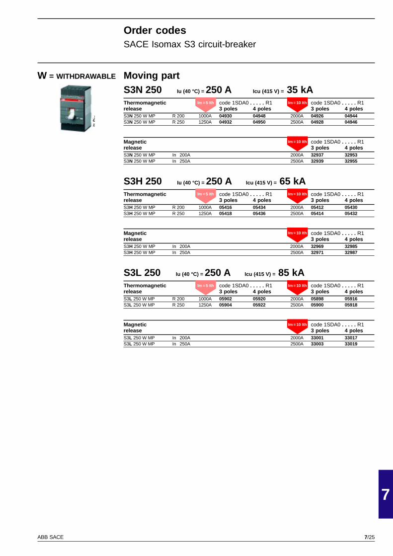
7/25
7
ABB SACE
PSIS9607
Moving partS3N 250 Iu (40 °C) = 250 A Icu (415 V) = 35 kAThermomagnetic code 1SDA0 . . . . . R1 code 1SDA0 . . . . . R1release 3 poles 4 poles 3 poles 4 polesS3N 250 W MP R 200 1000A 04930 04948 2000A 04926 04944S3N 250 W MP R 250 1250A 04932 04950 2500A 04928 04946
Magnetic code 1SDA0 . . . . . R1release 3 poles 4 polesS3N 250 W MP In 200A 2000A 32937 32953S3N 250 W MP In 250A 2500A 32939 32955
S3H 250 Iu (40 °C) = 250 A Icu (415 V) = 65 kAThermomagnetic code 1SDA0 . . . . . R1 code 1SDA0 . . . . . R1release 3 poles 4 poles 3 poles 4 polesS3H 250 W MP R 200 1000A 05416 05434 2000A 05412 05430S3H 250 W MP R 250 1250A 05418 05436 2500A 05414 05432
Magnetic code 1SDA0 . . . . . R1release 3 poles 4 polesS3H 250 W MP In 200A 2000A 32969 32985S3H 250 W MP In 250A 2500A 32971 32987
S3L 250 Iu (40 °C) = 250 A Icu (415 V) = 85 kAThermomagnetic code 1SDA0 . . . . . R1 code 1SDA0 . . . . . R1release 3 poles 4 poles 3 poles 4 polesS3L 250 W MP R 200 1000A 05902 05920 2000A 05898 05916S3L 250 W MP R 250 1250A 05904 05922 2500A 05900 05918
Magnetic code 1SDA0 . . . . . R1release 3 poles 4 polesS3L 250 W MP In 200A 2000A 33001 33017S3L 250 W MP In 250A 2500A 33003 33019
W = WITHDRAWABLE
Order codesSACE Isomax S3 circuit-breaker
Im = 5 Ith Im = 10 Ith
Im = 10 Ith
Im = 5 Ith Im = 10 Ith
Im = 10 Ith
Im = 5 Ith Im = 10 Ith
Im = 10 Ith
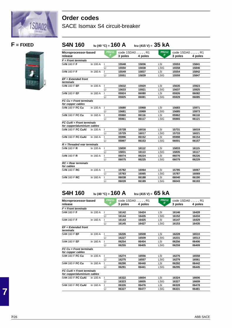
7/26
7
ABB SACE
PSIS9610
S4N 160 Iu (40 °C) = 160 A Icu (415 V) = 35 kAMicroprocessor-based code 1SDA0 . . . . . R1 code 1SDA0 . . . . . R1release 3 poles 4 poles 3 poles 4 polesF = Front terminalsS4N 160 F F In 100 A I 15548 15836 LSI 15553 15841
LI 15550 15838 LSIG 15558 15846S4N 160 F F In 160 A I 15549 15837 LSI 15554 15842
LI 15551 15839 LSIG 15559 15847EF = Extended frontterminalsS4N 160 F EF In 100 A I 15632 15920 LSI 15635 15923
LI 15633 15921 LSIG 15637 15925S4N 160 F EF In 160 A I 05924 06080 LSI 05926 06082
LI 05925 06081 LSIG 05929 06085FC Cu = Front terminalsfor copper cablesS4N 160 F FC Cu In 100 A I 15680 15968 LSI 15683 15971
LI 15681 15969 LSIG 15685 15973S4N 160 F FC Cu In 160 A I 05960 06116 LSI 05962 06118
LI 05961 06117 LSIG 05965 06121FC CuAl = Front terminalsfor copper/aluminium cablesS4N 160 F FC CuAl In 100 A I 15728 16016 LSI 15731 16019
LI 15729 16017 LSIG 15733 16021S4N 160 F FC CuAl In 160 A I 05996 06152 LSI 05998 06154
LI 05997 06153 LSIG 06001 06157R = Threaded rear terminalsS4N 160 F R In 100 A I 15830 16112 LSI 15833 16115
LI 15831 16113 LSIG 15835 16117S4N 160 F R In 160 A I 06074 06224 LSI 06076 06226
LI 06075 06225 LSIG 06079 06229RC = Rear terminalsfor cablesS4N 160 F RC In 100 A I 15782 16064 LSI 15785 16067
LI 15783 16065 LSIG 15787 16069S4N 160 F RC In 160 A I 06038 06188 LSI 06040 06190
LI 06039 06189 LSIG 06043 06193
S4H 160 Iu (40 °C) = 160 A Icu (415 V) = 65 kAMicroprocessor-based code 1SDA0 . . . . . R1 code 1SDA0 . . . . . R1release 3 poles 4 poles 3 poles 4 polesF = Front terminalsS4H 160 F F In 100 A I 16142 16424 LSI 16146 16428
LI 16144 16426 LSIG 16152 16434S4H 160 F F In 160 A I 16143 16425 LSI 16147 16429
LI 16145 16427 LSIG 16153 16435EF = Extended frontterminalsS4H 160 F EF In 100 A I 16226 16508 LSI 16228 16510
LI 16227 16509 LSIG 16231 16513S4H 160 F EF In 160 A I 06254 06404 LSI 06256 06406
LI 06255 06405 LSIG 06259 06409FC Cu = Front terminalsfor copper cablesS4H 160 F FC Cu In 100 A I 16274 16556 LSI 16276 16558
LI 16275 16557 LSIG 16279 16561S4H 160 F FC Cu In 160 A I 06290 06440 LSI 06292 06442
LI 06291 06441 LSIG 06295 06445FC CuAl = Front terminalsfor copper/aluminium cablesS4H 160 F FC CuAl In 100 A I 16322 16604 LSI 16324 16606
LI 16323 16605 LSIG 16327 16609S4H 160 F FC CuAl In 160 A I 06326 06476 LSI 06328 06478
LI 06327 06477 LSIG 06331 06481
F = FIXED
Order codesSACE Isomax S4 circuit-breaker
PR211P
PR212P
PR211P
PR212P
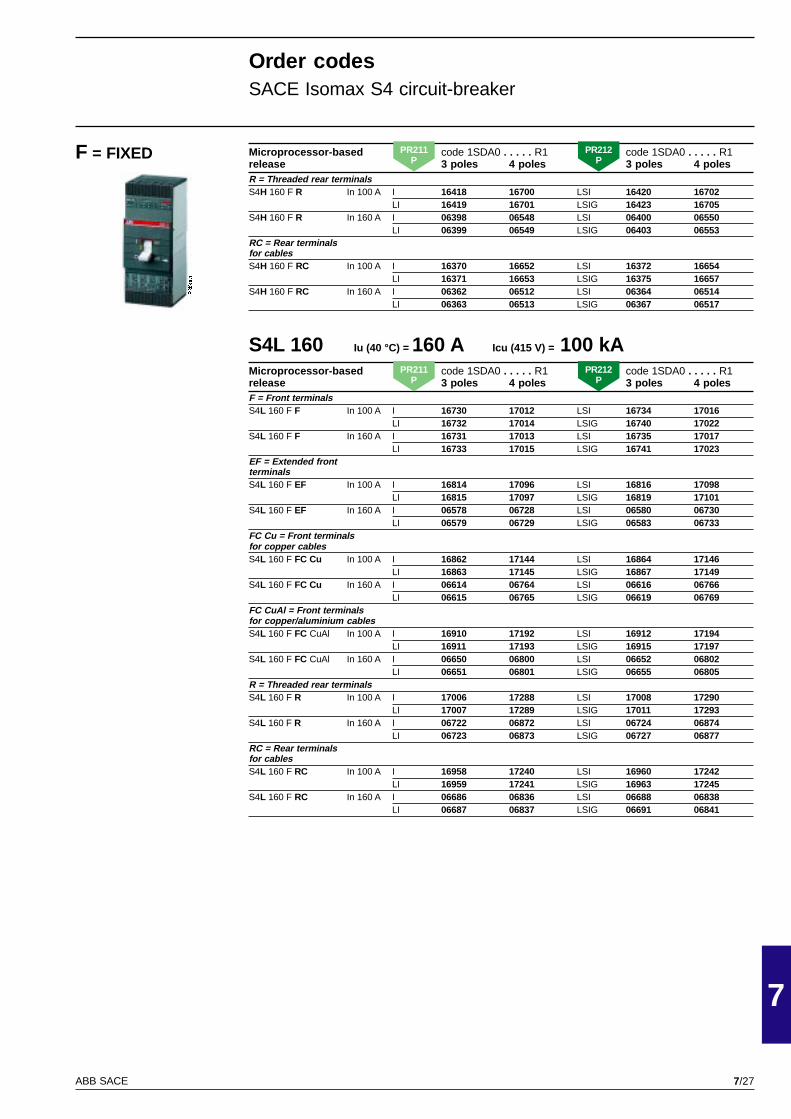
7/27
7
ABB SACE
PSIS9610
Microprocessor-based code 1SDA0 . . . . . R1 code 1SDA0 . . . . . R1release 3 poles 4 poles 3 poles 4 polesR = Threaded rear terminalsS4H 160 F R In 100 A I 16418 16700 LSI 16420 16702
LI 16419 16701 LSIG 16423 16705S4H 160 F R In 160 A I 06398 06548 LSI 06400 06550
LI 06399 06549 LSIG 06403 06553RC = Rear terminalsfor cablesS4H 160 F RC In 100 A I 16370 16652 LSI 16372 16654
LI 16371 16653 LSIG 16375 16657S4H 160 F RC In 160 A I 06362 06512 LSI 06364 06514
LI 06363 06513 LSIG 06367 06517
S4L 160 Iu (40 °C) = 160 A Icu (415 V) = 100 kAMicroprocessor-based code 1SDA0 . . . . . R1 code 1SDA0 . . . . . R1release 3 poles 4 poles 3 poles 4 polesF = Front terminalsS4L 160 F F In 100 A I 16730 17012 LSI 16734 17016
LI 16732 17014 LSIG 16740 17022S4L 160 F F In 160 A I 16731 17013 LSI 16735 17017
LI 16733 17015 LSIG 16741 17023EF = Extended frontterminalsS4L 160 F EF In 100 A I 16814 17096 LSI 16816 17098
LI 16815 17097 LSIG 16819 17101S4L 160 F EF In 160 A I 06578 06728 LSI 06580 06730
LI 06579 06729 LSIG 06583 06733FC Cu = Front terminalsfor copper cablesS4L 160 F FC Cu In 100 A I 16862 17144 LSI 16864 17146
LI 16863 17145 LSIG 16867 17149S4L 160 F FC Cu In 160 A I 06614 06764 LSI 06616 06766
LI 06615 06765 LSIG 06619 06769FC CuAl = Front terminalsfor copper/aluminium cablesS4L 160 F FC CuAl In 100 A I 16910 17192 LSI 16912 17194
LI 16911 17193 LSIG 16915 17197S4L 160 F FC CuAl In 160 A I 06650 06800 LSI 06652 06802
LI 06651 06801 LSIG 06655 06805R = Threaded rear terminalsS4L 160 F R In 100 A I 17006 17288 LSI 17008 17290
LI 17007 17289 LSIG 17011 17293S4L 160 F R In 160 A I 06722 06872 LSI 06724 06874
LI 06723 06873 LSIG 06727 06877RC = Rear terminalsfor cablesS4L 160 F RC In 100 A I 16958 17240 LSI 16960 17242
LI 16959 17241 LSIG 16963 17245S4L 160 F RC In 160 A I 06686 06836 LSI 06688 06838
LI 06687 06837 LSIG 06691 06841
Order codesSACE Isomax S4 circuit-breaker
F = FIXED PR211P
PR212P
PR211P
PR212P
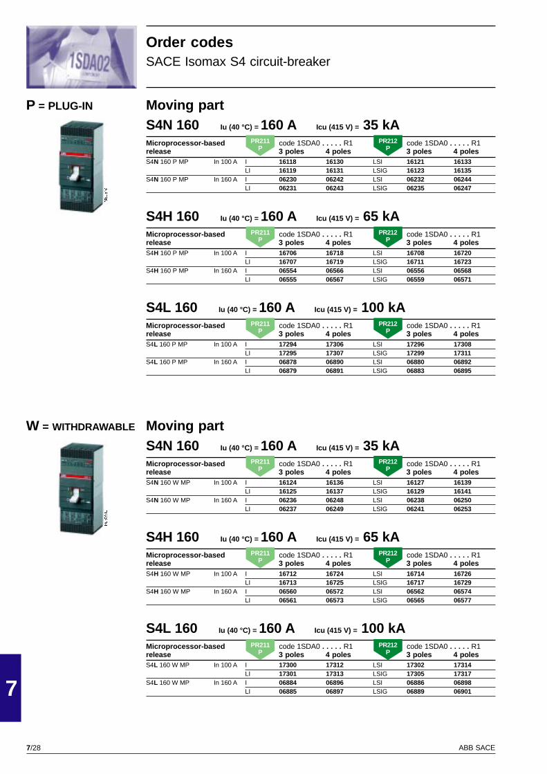
7/28
7
ABB SACE
PSIS9610
PSIS9610
Moving partS4N 160 Iu (40 °C) = 160 A Icu (415 V) = 35 kAMicroprocessor-based code 1SDA0 . . . . . R1 code 1SDA0 . . . . . R1release 3 poles 4 poles 3 poles 4 polesS4N 160 W MP In 100 A I 16124 16136 LSI 16127 16139
LI 16125 16137 LSIG 16129 16141S4N 160 W MP In 160 A I 06236 06248 LSI 06238 06250
LI 06237 06249 LSIG 06241 06253
S4H 160 Iu (40 °C) = 160 A Icu (415 V) = 65 kAMicroprocessor-based code 1SDA0 . . . . . R1 code 1SDA0 . . . . . R1release 3 poles 4 poles 3 poles 4 polesS4H 160 W MP In 100 A I 16712 16724 LSI 16714 16726
LI 16713 16725 LSIG 16717 16729S4H 160 W MP In 160 A I 06560 06572 LSI 06562 06574
LI 06561 06573 LSIG 06565 06577
S4L 160 Iu (40 °C) = 160 A Icu (415 V) = 100 kAMicroprocessor-based code 1SDA0 . . . . . R1 code 1SDA0 . . . . . R1release 3 poles 4 poles 3 poles 4 polesS4L 160 W MP In 100 A I 17300 17312 LSI 17302 17314
LI 17301 17313 LSIG 17305 17317S4L 160 W MP In 160 A I 06884 06896 LSI 06886 06898
LI 06885 06897 LSIG 06889 06901
Moving partS4N 160 Iu (40 °C) = 160 A Icu (415 V) = 35 kAMicroprocessor-based code 1SDA0 . . . . . R1 code 1SDA0 . . . . . R1release 3 poles 4 poles 3 poles 4 polesS4N 160 P MP In 100 A I 16118 16130 LSI 16121 16133
LI 16119 16131 LSIG 16123 16135S4N 160 P MP In 160 A I 06230 06242 LSI 06232 06244
LI 06231 06243 LSIG 06235 06247
S4H 160 Iu (40 °C) = 160 A Icu (415 V) = 65 kAMicroprocessor-based code 1SDA0 . . . . . R1 code 1SDA0 . . . . . R1release 3 poles 4 poles 3 poles 4 polesS4H 160 P MP In 100 A I 16706 16718 LSI 16708 16720
LI 16707 16719 LSIG 16711 16723S4H 160 P MP In 160 A I 06554 06566 LSI 06556 06568
LI 06555 06567 LSIG 06559 06571
S4L 160 Iu (40 °C) = 160 A Icu (415 V) = 100 kAMicroprocessor-based code 1SDA0 . . . . . R1 code 1SDA0 . . . . . R1release 3 poles 4 poles 3 poles 4 polesS4L 160 P MP In 100 A I 17294 17306 LSI 17296 17308
LI 17295 17307 LSIG 17299 17311S4L 160 P MP In 160 A I 06878 06890 LSI 06880 06892
LI 06879 06891 LSIG 06883 06895
P = PLUG-IN
W = WITHDRAWABLE
Order codesSACE Isomax S4 circuit-breaker
PR211P
PR212P
PR211P
PR212P
PR211P
PR212P
PR211P
PR212P
PR211P
PR212P
PR211P
PR212P

7/29
7
ABB SACE
PSIS9610
S4N 250 Iu (40 °C) = 250 A Icu (415 V) = 35 kAMicroprocessor-based code 1SDA0 . . . . . R1 code 1SDA0 . . . . . R1release 3 poles 4 poles 3 poles 4 polesF = Front terminalsS4N 250 F F In 250 A I 17318 17384 LSI 17320 17386
LI 17319 17385 LSIG 17323 17389EF = Extended front terminalsS4N 250 F EF In 250 A I 06902 07052 LSI 06904 07054
LI 06903 07053 LSIG 06907 07057FC Cu = Front terminalsfor copper cablesS4N 250 F FC Cu In 250 A I 06938 07088 LSI 06940 07090
LI 06939 07089 LSIG 06943 07093FC CuAl = Front terminalsfor copper/aluminium cablesS4N 250 F FC CuAl In 250 A I 06974 07124 LSI 06976 07126
LI 06975 07125 LSIG 06979 07129R = Threaded rear terminalsS4N 250 F R In 250 A I 07046 07196 LSI 07048 07198
LI 07047 07197 LSIG 07051 07201RC = Rear terminals for cablesS4N 250 F RC In 250 A I 07010 07160 LSI 07012 07162
LI 07011 07161 LSIG 07015 07165
S4H 250 Iu (40 °C) = 250 A Icu (415 V) = 65 kAMicroprocessor-based code 1SDA0 . . . . . R1 code 1SDA0 . . . . . R1release 3 poles 4 poles 3 poles 4 polesF = Front terminalsS4H 250 F F In 250 A I 17450 17516 LSI 17452 17518
LI 17451 17517 LSIG 17455 17521EF = Extended front terminalsS4H 250 F EF In 250 A I 07226 07376 LSI 07228 07378
LI 07227 07377 LSIG 07231 07381FC Cu = Front terminalsfor copper cablesS4H 250 F FC Cu In 250 A I 07262 07412 LSI 07264 07414
LI 07263 07413 LSIG 07267 07417FC CuAl = Front terminalsfor copper/aluminium cablesS4H 250 F FC CuAl In 250 A I 07298 07448 LSI 07300 07450
LI 07299 07449 LSIG 07303 07453R = Threaded rear terminalsS4H 250 F R In 250 A I 07370 07520 LSI 07372 07522
LI 07371 07521 LSIG 07375 07525RC = Rear terminals for cablesS4H 250 F RC In 250 A I 07334 07484 LSI 07336 07486
LI 07335 07485 LSIG 07339 07489
Order codesSACE Isomax S4 circuit-breaker
F = FIXEDPR211
PPR212
P
PR211P
PR212P
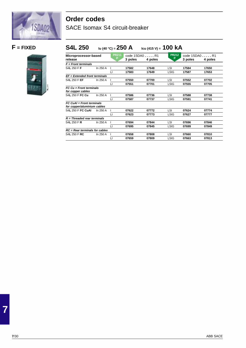
7/30
7
ABB SACE
PSIS9610
S4L 250 Iu (40 °C) = 250 A Icu (415 V) = 100 kAMicroprocessor-based code 1SDA0 . . . . . R1 code 1SDA0 . . . . . R1release 3 poles 4 poles 3 poles 4 polesF = Front terminalsS4L 250 F F In 250 A I 17582 17648 LSI 17584 17650
LI 17583 17649 LSIG 17587 17653EF = Extended front terminalsS4L 250 F EF In 250 A I 07550 07700 LSI 07552 07702
LI 07551 07701 LSIG 07555 07705FC Cu = Front terminalsfor copper cablesS4L 250 F FC Cu In 250 A I 07586 07736 LSI 07588 07738
LI 07587 07737 LSIG 07591 07741FC CuAl = Front terminalsfor copper/aluminium cablesS4L 250 F FC CuAl In 250 A I 07622 07772 LSI 07624 07774
LI 07623 07773 LSIG 07627 07777R = Threaded rear terminalsS4L 250 F R In 250 A I 07694 07844 LSI 07696 07846
LI 07695 07845 LSIG 07699 07849RC = Rear terminals for cablesS4L 250 F RC In 250 A I 07658 07808 LSI 07660 07810
LI 07659 07809 LSIG 07663 07813
F = FIXED
Order codesSACE Isomax S4 circuit-breaker
PR211P
PR212P
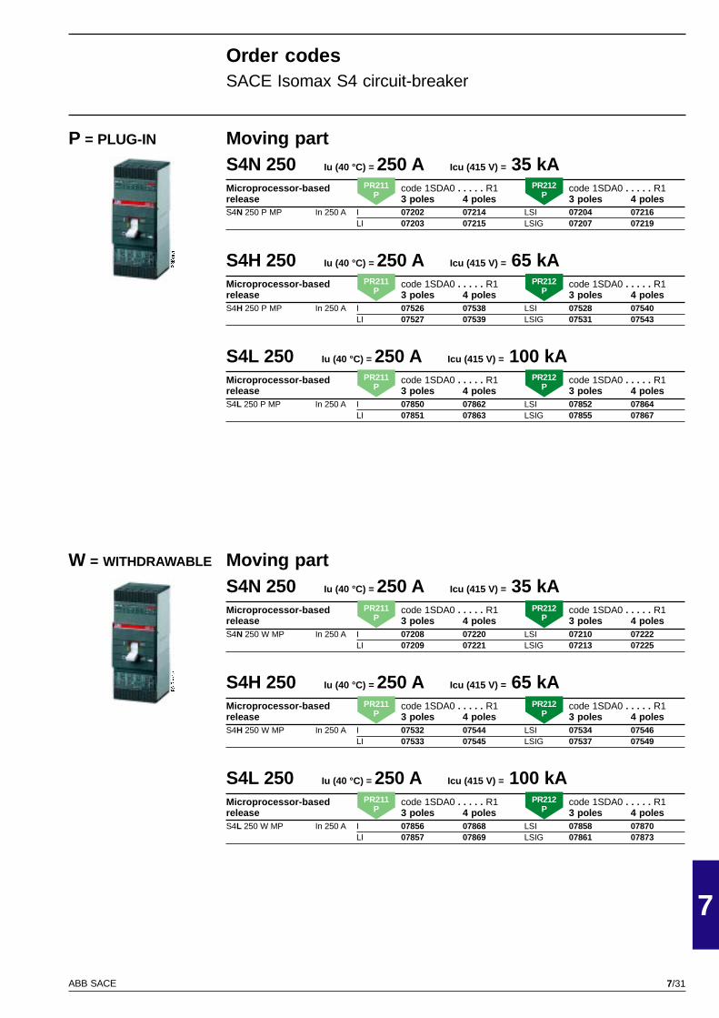
7/31
7
ABB SACE
PSIS9610
PSIS9610
Moving partS4N 250 Iu (40 °C) = 250 A Icu (415 V) = 35 kAMicroprocessor-based code 1SDA0 . . . . . R1 code 1SDA0 . . . . . R1release 3 poles 4 poles 3 poles 4 polesS4N 250 W MP In 250 A I 07208 07220 LSI 07210 07222
LI 07209 07221 LSIG 07213 07225
S4H 250 Iu (40 °C) = 250 A Icu (415 V) = 65 kAMicroprocessor-based code 1SDA0 . . . . . R1 code 1SDA0 . . . . . R1release 3 poles 4 poles 3 poles 4 polesS4H 250 W MP In 250 A I 07532 07544 LSI 07534 07546
LI 07533 07545 LSIG 07537 07549
S4L 250 Iu (40 °C) = 250 A Icu (415 V) = 100 kAMicroprocessor-based code 1SDA0 . . . . . R1 code 1SDA0 . . . . . R1release 3 poles 4 poles 3 poles 4 polesS4L 250 W MP In 250 A I 07856 07868 LSI 07858 07870
LI 07857 07869 LSIG 07861 07873
Moving partS4N 250 Iu (40 °C) = 250 A Icu (415 V) = 35 kAMicroprocessor-based code 1SDA0 . . . . . R1 code 1SDA0 . . . . . R1release 3 poles 4 poles 3 poles 4 polesS4N 250 P MP In 250 A I 07202 07214 LSI 07204 07216
LI 07203 07215 LSIG 07207 07219
S4H 250 Iu (40 °C) = 250 A Icu (415 V) = 65 kAMicroprocessor-based code 1SDA0 . . . . . R1 code 1SDA0 . . . . . R1release 3 poles 4 poles 3 poles 4 polesS4H 250 P MP In 250 A I 07526 07538 LSI 07528 07540
LI 07527 07539 LSIG 07531 07543
S4L 250 Iu (40 °C) = 250 A Icu (415 V) = 100 kAMicroprocessor-based code 1SDA0 . . . . . R1 code 1SDA0 . . . . . R1release 3 poles 4 poles 3 poles 4 polesS4L 250 P MP In 250 A I 07850 07862 LSI 07852 07864
LI 07851 07863 LSIG 07855 07867
P = PLUG-IN
W = WITHDRAWABLE
Order codesSACE Isomax S4 circuit-breaker
PR211P
PR212P
PR211P
PR212P
PR211P
PR212P
PR211P
PR212P
PR211P
PR212P
PR211P
PR212P

7/32
7
ABB SACE
PSIS9613
S5N 400 Iu (40 °C) = 400 A Icu (415 V) = 35 kAThermomagnetic code 1SDA0 . . . . . R1release 3 poles 4 polesF = Front terminalsS5N 400 F F R 320 3200A 38438 38440S5N 400 F F R 400 4000A 38439 38441EF = Extended frontterminalsS5N 400 F EF R 320 3200A 38442 38444S5N 400 F EF R 400 4000A 38443 38445FC Cu = Front terminalsfor copper cablesS5N 400 F FC Cu R 320 3200A 38446 38448S5N 400 F FC Cu R 400 4000A 38447 38449FC CuAl = Front terminalsfor copper/aluminium cablesS5N 400 F FC CuAl* R 320 3200A 38450 38452S5N 400 F FC CuAl* R 400 4000A 38451 38453S5N 400 F FC CuAl** R 320 3200A 38466 38480S5N 400 F FC CuAl** R 400 4000A 38467 38481R = Threaded rear terminalsS5N 400 F R R 320 3200A 38486 38488S5N 400 F R R 400 4000A 38487 38489RC = Rear terminalsfor cablesS5N 400 F RC R 320 3200A 38482 38484S5N 400 F RC R 400 4000A 38483 38485
Microprocessor-based code 1SDA0 . . . . . R1 code 1SDA0 . . . . . R1release 3 poles 4 poles 3 poles 4 polesF = Front terminalsS5N 400 F F In 320 A I 17714 17846 LSI 17718 17850
LI 17716 17848 LSIG 17724 17856S5N 400 F F In 400 A I 17715 17847 LSI 17719 17851
LI 17717 17849 LSIG 17725 17857EF = Extended frontterminalsS5N 400 F EF In 320 A I 07874 08174 LSI 07878 08178
LI 07876 08176 LSIG 07884 08184S5N 400 F EF In 400 A I 07875 08175 LSI 07879 08179
LI 07877 08177 LSIG 07885 08185FC Cu = Front terminalsfor copper cablesS5N 400 F FC Cu In 320 A I 07946 08246 LSI 07950 08250
LI 07948 08248 LSIG 07956 08256S5N 400 F FC Cu In 400 A I 07947 08247 LSI 07951 08251
LI 07949 08249 LSIG 07957 08257FC CuAl = Front terminalsfor copper/aluminium cablesS5N 400 F FC CuAl* In 320 A I 08018 08318 LSI 08022 08322
LI 08020 08320 LSIG 08028 08328S5N 400 F FC CuAl* In 400 A I 08019 08319 LSI 08023 08323
LI 08021 08321 LSIG 08029 08329S5N 400 F FC CuAl** In 320 A I 38454 38468 LSI 38458 38472
LI 38456 38470 LSIG 38464 38478S5N 400 F FC CuAl** In 400 A I 38455 38469 LSI 38459 38473
LI 38457 38471 LSIG 38465 38479R = Threaded rear terminalsS5N 400 F R In 320 A I 08162 08450 LSI 08166 08454
LI 08164 08452 LSIG 08172 08460S5N 400 F R In 400 A I 08163 08451 LSI 08167 08455
LI 08165 08453 LSIG 08173 08461RC = Rear terminalsfor cablesS5N 400 F RC In 320 A I 08090 08390 LSI 08094 08394
LI 08092 08392 LSIG 08100 08400S5N 400 F RC In 400 A I 08091 08391 LSI 08095 08395
LI 08093 08393 LSIG 08101 08401
* Cable section = 1 x 240 mm2
** Cable section = 2 x 120 mm2
F = FIXED
Order codesSACE Isomax S5 circuit-breaker
PR211P
PR212P
Im = 5...10Ith
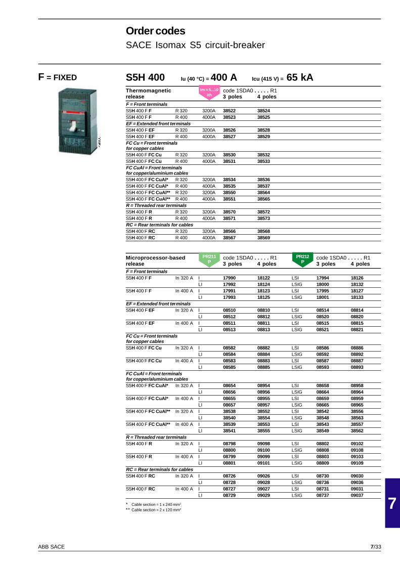
7/33
7
ABB SACE
PSIS9613
S5H 400 Iu (40 °C) = 400 A Icu (415 V) = 65 kAThermomagnetic code 1SDA0 . . . . . R1release 3 poles 4 polesF = Front terminalsS5H 400 F F R 320 3200A 38522 38524S5H 400 F F R 400 4000A 38523 38525EF = Extended front te rminalsS5H 400 F EF R 320 3200A 38526 38528S5H 400 F EF R 400 4000A 38527 38529FC Cu = Front terminalsfor copper cablesS5H 400 F FC Cu R 320 3200A 38530 38532S5H 400 F FC Cu R 400 4000A 38531 38533FC CuAl = Front terminalsfor copper/aluminium cablesS5H 400 F FC CuAl* R 320 3200A 38534 38536S5H 400 F FC CuAl* R 400 4000A 38535 38537S5H 400 F FC CuAl** R 320 3200A 38550 38564S5H 400 F FC CuAl** R 400 4000A 38551 38565R = Threaded rear terminalsS5H 400 F R R 320 3200A 38570 38572S5H 400 F R R 400 4000A 38571 38573RC = Rear terminals for cablesS5H 400 F RC R 320 3200A 38566 38568S5H 400 F RC R 400 4000A 38567 38569
Microprocessor-based code 1SDA0 . . . . . R1 code 1SDA0 . . . . . R1release 3 poles 4 poles 3 poles 4 polesF = Front terminalsS5H 400 F F In 320 A I 17990 18122 LSI 17994 18126
LI 17992 18124 LSIG 18000 18132S5H 400 F F In 400 A I 17991 18123 LSI 17995 18127
LI 17993 18125 LSIG 18001 18133EF = Extended front te rminalsS5H 400 F EF In 320 A I 08510 08810 LSI 08514 08814
LI 08512 08812 LSIG 08520 08820S5H 400 F EF In 400 A I 08511 08811 LSI 08515 08815
LI 08513 08813 LSIG 08521 08821FC Cu = Front terminalsfor copper cablesS5H 400 F FC Cu In 320 A I 08582 08882 LSI 08586 08886
LI 08584 08884 LSIG 08592 08892S5H 400 F FC Cu In 400 A I 08583 08883 LSI 08587 08887
LI 08585 08885 LSIG 08593 08893FC CuAl = Front terminalsfor copper/aluminium cablesS5H 400 F FC CuAl* In 320 A I 08654 08954 LSI 08658 08958
LI 08656 08956 LSIG 08664 08964S5H 400 F FC CuAl* In 400 A I 08655 08955 LSI 08659 08959
LI 08657 08957 LSIG 08665 08965S5H 400 F FC CuAl** In 320 A I 38538 38552 LSI 38542 38556
LI 38540 38554 LSIG 38548 38563S5H 400 F FC CuAl** In 400 A I 38539 38553 LSI 38543 38557
LI 38541 38555 LSIG 38549 38562R = Threaded rear terminalsS5H 400 F R In 320 A I 08798 09098 LSI 08802 09102
LI 08800 09100 LSIG 08808 09108S5H 400 F R In 400 A I 08799 09099 LSI 08803 09103
LI 08801 09101 LSIG 08809 09109RC = Rear terminals for cablesS5H 400 F RC In 320 A I 08726 09026 LSI 08730 09030
LI 08728 09028 LSIG 08736 09036S5H 400 F RC In 400 A I 08727 09027 LSI 08731 09031
LI 08729 09029 LSIG 08737 09037
F = FIXED
Order codesSACE Isomax S5 circuit-breaker
* Cable section = 1 x 240 mm2
** Cable section = 2 x 120 mm2
Im = 5...10Ith
PR211P
PR212P

7/34
7
ABB SACE
PSIS9613
S5L 400 Iu (40 °C) = 400 A Icu (415 V) = 100 kAThermomagnetic code 1SDA0 . . . . . R1release 3 poles 4 polesF = Front terminalsS5L 400 F F R 320 3200A 38606 38608S5L 400 F F R 400 4000A 38607 38609EF = Extended front te rminalsS5L 400 F EF R 320 3200A 38610 38612S5L 400 F EF R 400 4000A 38611 38613FC Cu = Front terminalsfor copper cablesS5L 400 F FC Cu R 320 3200A 38614 38616S5L 400 F FC Cu R 400 4000A 38615 38617FC CuAl = Front terminalsfor copper/aluminium cablesS5L 400 F FC CuAl* R 320 3200A 38618 38620S5L 400 F FC CuAl* R 400 4000A 38619 38621S5L 400 F FC CuAl** R 320 3200A 38634 38648S5L 400 F FC CuAl** R 400 4000A 38635 38649R = Threaded rear terminalsS5L 400 F R R 320 3200A 38654 38656S5L 400 F R R 400 4000A 38655 38657RC = Rear terminals for cablesS5L 400 F RC R 320 3200A 38650 38652S5L 400 F RC R 400 4000A 38651 38653
Microprocessor-based code 1SDA0 . . . . . R1 code 1SDA0 . . . . . R1release 3 poles 4 poles 3 poles 4 polesF = Front terminalsS5L 400 F F In 320 A I 18254 18386 LSI 18258 18390
LI 18256 18388 LSIG 18264 18396S5L 400 F F In 400 A I 18255 18387 LSI 18259 18391
LI 18257 18389 LSIG 18265 18397EF = Extended front te rminalsS5L 400 F EF In 320 A I 09158 09458 LSI 09162 09462
LI 09160 09460 LSIG 09168 09468S5L 400 F EF In 400 A I 09159 09459 LSI 09163 09463
LI 09161 09461 LSIG 09169 09469FC Cu = Front terminalsfor copper cablesS5L 400 F FC Cu In 320 A I 09230 09530 LSI 09234 09534
LI 09232 09532 LSIG 09240 09540S5L 400 F FC Cu In 400 A I 09231 09531 LSI 09235 09535
LI 09233 09533 LSIG 09241 09541FC CuAl = Front terminalsfor copper/aluminium cablesS5L 400 F FC CuAl* In 320 A I 09302 09602 LSI 09306 09606
LI 09304 09604 LSIG 09312 09612S5L 400 F FC CuAl* In 400 A I 09303 09603 LSI 09307 09607
LI 09305 09605 LSIG 09313 09613S5L 400 F FC CuAl** In 320 A I 38622 38636 LSI 38626 38640
LI 38624 38638 LSIG 38628 38646S5L 400 F FC CuAl** In 400 A I 38623 38637 LSI 38627 38641
LI 38625 38639 LSIG 38629 38647R = Threaded rear terminalsS5L 400 F R In 320 A I 09446 09746 LSI 09450 09750
LI 09448 09748 LSIG 09456 09756S5L 400 F R In 400 A I 09447 09747 LSI 09451 09751
LI 09449 09749 LSIG 09457 09757RC = Rear terminals for cablesS5L 400 F RC In 320 A I 09374 09674 LSI 09378 09678
LI 09376 09676 LSIG 09384 09684S5L 400 F RC In 400 A I 09375 09675 LSI 09379 09679
LI 09377 09677 LSIG 09385 09685
F = FIXED
Order codesSACE Isomax S5 circuit-breaker
* Cable section = 1 x 240 mm2
** Cable section = 2 x 120 mm2
Im = 5...10Ith
PR211P
PR212P
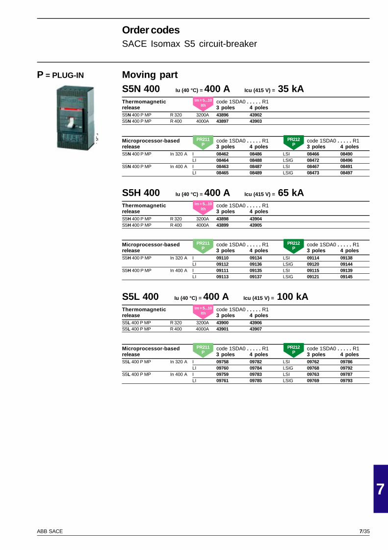
7/35
7
ABB SACE
PSIS9613
Moving partS5N 400 Iu (40 °C) = 400 A Icu (415 V) = 35 kAThermomagnetic code 1SDA0 . . . . . R1release 3 poles 4 polesS5N 400 P MP R 320 3200A 43896 43902S5N 400 P MP R 400 4000A 43897 43903
Microprocessor-based code 1SDA0 . . . . . R1 code 1SDA0 . . . . . R1release 3 poles 4 poles 3 poles 4 polesS5N 400 P MP In 320 A I 08462 08486 LSI 08466 08490
LI 08464 08488 LSIG 08472 08496S5N 400 P MP In 400 A I 08463 08487 LSI 08467 08491
LI 08465 08489 LSIG 08473 08497
S5H 400 Iu (40 °C) = 400 A Icu (415 V) = 65 kAThermomagnetic code 1SDA0 . . . . . R1release 3 poles 4 polesS5H 400 P MP R 320 3200A 43898 43904S5H 400 P MP R 400 4000A 43899 43905
Microprocessor-based code 1SDA0 . . . . . R1 code 1SDA0 . . . . . R1release 3 poles 4 poles 3 poles 4 polesS5H 400 P MP In 320 A I 09110 09134 LSI 09114 09138
LI 09112 09136 LSIG 09120 09144S5H 400 P MP In 400 A I 09111 09135 LSI 09115 09139
LI 09113 09137 LSIG 09121 09145
S5L 400 Iu (40 °C) = 400 A Icu (415 V) = 100 kAThermomagnetic code 1SDA0 . . . . . R1release 3 poles 4 polesS5L 400 P MP R 320 3200A 43900 43906S5L 400 P MP R 400 4000A 43901 43907
Microprocessor-based code 1SDA0 . . . . . R1 code 1SDA0 . . . . . R1release 3 poles 4 poles 3 poles 4 polesS5L 400 P MP In 320 A I 09758 09782 LSI 09762 09786
LI 09760 09784 LSIG 09768 09792S5L 400 P MP In 400 A I 09759 09783 LSI 09763 09787
LI 09761 09785 LSIG 09769 09793
P = PLUG-IN
Order codesSACE Isomax S5 circuit-breaker
Im = 5...10Ith
Im = 5...10Ith
Im = 5...10Ith
PR211P
PR212P
PR211P
PR212P
PR211P
PR212P

7/36
7
ABB SACE
PSIS9613
Moving partS5N 400 Iu (40 °C) = 400 A Icu (415 V) = 35 kAThermomagnetic code 1SDA0 . . . . . R1release 3 poles 4 polesS5N 400 W MP R 320 3200A 38414 38416S5N 400 W MP R 400 4000A 38415 38417
Microprocessor-based code 1SDA0 . . . . . R1 code 1SDA0 . . . . . R1release 3 poles 4 poles 3 poles 4 polesS5N 400 W MP In 320 A I 08474 08498 LSI 08478 08502
LI 08476 08500 LSIG 08484 08508S5N 400 W MP In 400 A I 08475 08499 LSI 08479 08503
LI 08477 08501 LSIG 08485 08509
S5H 400 Iu (40 °C) = 400 A Icu (415 V) = 65 kAThermomagnetic code 1SDA0 . . . . . R1release 3 poles 4 polesS5H 400 W MP R 320 3200A 38490 38492S5H 400 W MP R 400 4000A 38491 38493
Microprocessor-based code 1SDA0 . . . . . R1 code 1SDA0 . . . . . R1release 3 poles 4 poles 3 poles 4 polesS5H 400 W MP In 320 A I 09122 09146 LSI 09126 09150
LI 09124 09148 LSIG 09132 09156S5H 400 W MP In 400 A I 09123 09147 LSI 09127 09151
LI 09125 09149 LSIG 09133 09157
S5L 400 Iu (40 °C) = 400 A Icu (415 V) = 100 kAThermomagnetic code 1SDA0 . . . . . R1release 3 poles 4 polesS5L 400 W MP R 320 3200A 38574 38576S5L 400 W MP R 400 4000A 38575 38577
Microprocessor-based code 1SDA0 . . . . . R1 code 1SDA0 . . . . . R1release 3 poles 4 poles 3 poles 4 polesS5L 400 W MP In 320 A I 09770 09794 LSI 09774 09798
LI 09772 09796 LSIG 09780 09804S5L 400 W MP In 400 A I 09771 09795 LSI 09775 09799
LI 09773 09797 LSIG 09781 09805
W = WITHDRAWABLE
Order codesSACE Isomax S5 circuit-breaker
Im = 5...10Ith
Im = 5...10Ith
Im = 5...10Ith
PR211P
PR212P
PR211P
PR212P
PR211P
PR212P
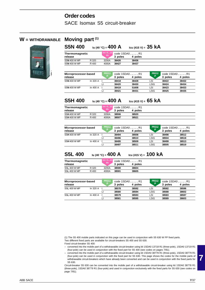
7/37
7
ABB SACE
PSIS9613
Moving part (1)
S5N 400 Iu (40 °C) = 400 A Icu (415 V) = 35 kAThermomagnetic code 1SDA0 . . . . . R1release 3 poles 4 polesS5N 400 W MP R 320 3200A 38426 38436S5N 400 W MP R 400 4000A 38427 38437
Microprocessor-based code 1SDA0 . . . . . R1 code 1SDA0 . . . . . R1release 3 poles 4 poles 3 poles 4 polesS5N 400 W MP In 320 A I 38418 38428 LSI 38422 38432
LI 38420 38430 LSIG 38424 38434S5N 400 W MP In 400 A I 38419 51608 LSI 38423 38433
LI 38421 38431 LSIG 38425 38435
S5H 400 Iu (40 °C) = 400 A Icu (415 V) = 65 kAThermomagnetic code 1SDA0 . . . . . R1release 3 poles 4 polesS5H 400 W MP R 320 3200A 38506 38520S5H 400 W MP R 400 4000A 38507 38521
Microprocessor-based code 1SDA0 . . . . . R1 code 1SDA0 . . . . . R1release 3 poles 4 poles 3 poles 4 polesS5H 400 W MP In 320 A I 38494 38508 LSI 38498 38512
LI 38496 38510 LSIG 38504 38518S5H 400 W MP In 400 A I 38495 38509 LSI 38499 38513
LI 38497 38511 LSIG 38505 38519
S5L 400 Iu (40 °C) = 400 A Icu (415 V) = 100 kAThermomagnetic code 1SDA0 . . . . . R1release 3 poles 4 polesS5L 400 W MP R 320 3200A 38590 38604S5L 400 W MP R 400 4000A 38591 38605
Microprocessor-based code 1SDA0 . . . . . R1 code 1SDA0 . . . . . R1release 3 poles 4 poles 3 poles 4 polesS5L 400 W MP In 320 A I 38578 38592 LSI 38582 38596
LI 38580 38594 LSIG 38588 38602S5L 400 W MP In 400 A I 38579 38593 LSI 38583 38597
LI 38581 38595 LSIG 38589 38603
W = WITHDRAWABLE
Order codesSACE Isomax S5 circuit-breaker
(1) The S5 400 mobile parts indicated on this page can be used in conjunction with S5 630 W FP fixed parts.Two different fixed parts are available for circuit-breakers S5 400 and S5 630.Fixed circuit-breaker S5 400:– converted into the mobile part of a withdrawable circuit-breaker using kit 1SDA0 13718 R1 (three-pole), 1SDA0 13719 R1
(four-pole) can be used in conjunction with the fixed part for S5 400 (see codes on pages 7/81).– converted into the mobile part of a withdrawable circuit-breaker using kit 1SDA0 38778 R1 (three-pole), 1SDA0 38779 R1
(four-pole) can be used in conjunction with the fixed part for S5 630. This page shows the codes for the mobile parts ofwithdrawable circuit-breakers which have already been converted and can be used in conjunction with the fixed parts forS5 630.
Circuit-breaker S5 630 can be converted into the mobile part of a withdrawable circuit-breaker using kit 1SDA0 38778 R1(three-pole), 1SDA0 38779 R1 (four-pole) and used in conjunction exclusively with the fixed parts for S5 630 (see codes onpage 7/81).
Im = 5...10Ith
Im = 5...10Ith
Im = 5...10Ith
PR211P
PR212P
PR211P
PR212P
PR211P
PR212P
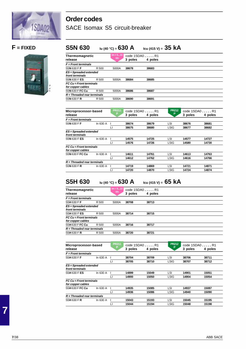
7/38
7
ABB SACE
PSIS9613
S5N 630 Iu (40 °C) = 630 A Icu (415 V) = 35 kAThermomagnetic code 1SDA0 . . . . . R1release 3 poles 4 polesF = Front terminalsS5N 630 F F R 500 5000A 38678 38683ES = Spreaded extendedfront terminalsS5N 630 F ES R 500 5000A 38684 38685FC Cu = Front terminalsfor copper cablesS5N 630 F FC Cu R 500 5000A 38686 38687R = Threaded rear terminalsS5N 630 F R R 500 5000A 38690 38691
Microprocessor-based code 1SDA0 . . . . . R1 code 1SDA0 . . . . . R1release 3 poles 4 poles 3 poles 4 polesF = Front terminalsS5N 630 F F In 630 A I 38674 38679 LSI 38676 38681
LI 38675 38680 LSIG 38677 38682ES = Spreaded extendedfront terminalsS5N 630 F ES In 630 A I 14575 14725 LSI 14577 14727
LI 14576 14726 LSIG 14580 14730FC Cu = Front terminalsfor copper cablesS5N 630 F FC Cu In 630 A I 14611 14761 LSI 14613 14763
LI 14612 14762 LSIG 14616 14766R = Threaded rear terminalsS5N 630 F R In 630 A I 14719 14869 LSI 14721 14871
LI 14720 14870 LSIG 14724 14874
S5H 630 Iu (40 °C) = 630 A Icu (415 V) = 65 kAThermomagnetic code 1SDA0 . . . . . R1release 3 poles 4 polesF = Front terminalsS5H 630 F F R 500 5000A 38708 38713ES = Spreaded extendedfront terminalsS5H 630 F ES R 500 5000A 38714 38715FC Cu = Front terminalsfor copper cablesS5H 630 F FC Cu R 500 5000A 38716 38717R = Threaded rear terminalsS5H 630 F R R 500 5000A 38720 38721
Microprocessor-based code 1SDA0 . . . . . R1 code 1SDA0 . . . . . R1release 3 poles 4 poles 3 poles 4 polesF = Front terminalsS5H 630 F F In 630 A I 38704 38709 LSI 38706 38711
LI 38705 38710 LSIG 38707 38712ES = Spreaded extendedfront terminalsS5H 630 F ES In 630 A I 14899 15049 LSI 14901 15051
LI 14900 15050 LSIG 14904 15054FC Cu = Front terminalsfor copper cablesS5H 630 F FC Cu In 630 A I 14935 15085 LSI 14937 15087
LI 14936 15086 LSIG 14940 15090R = Threaded rear terminalsS5H 630 F R In 630 A I 15043 15193 LSI 15045 15195
LI 15044 15194 LSIG 15048 15198
F = FIXED
Order codesSACE Isomax S5 circuit-breaker
Im = 5...10Ith
Im = 5...10Ith
PR211P
PR212P
PR211P
PR212P
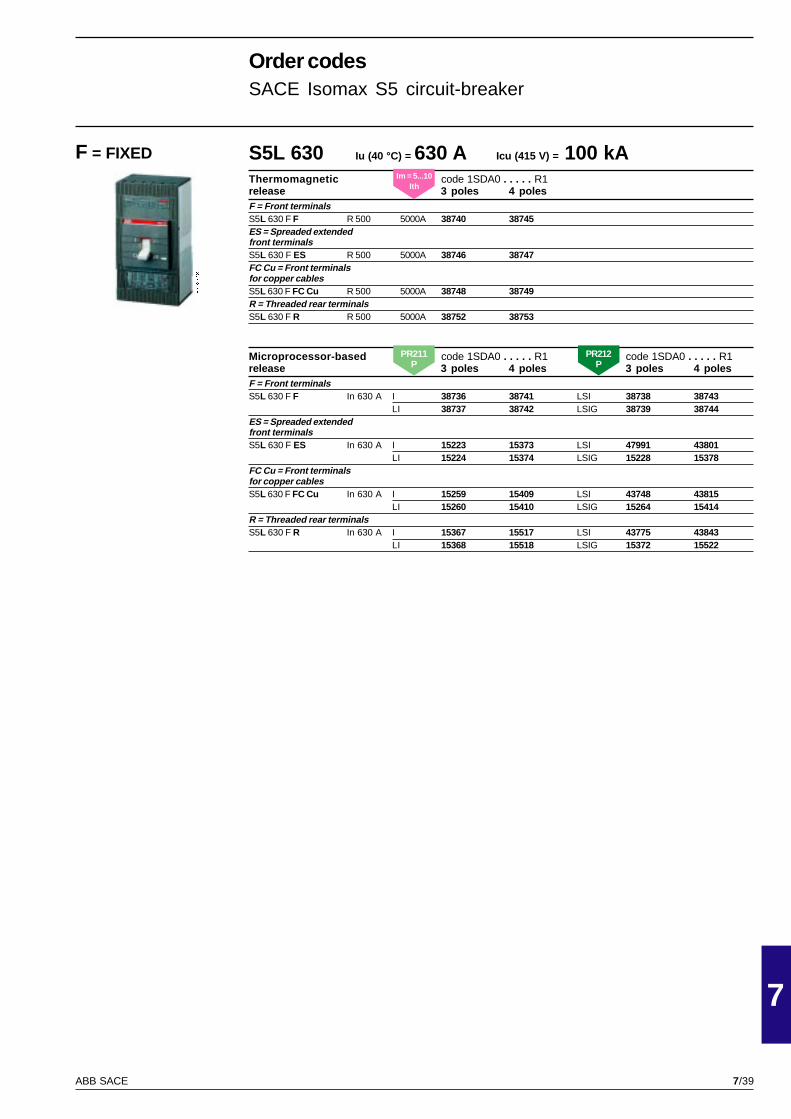
7/39
7
ABB SACE
PSIS9613
S5L 630 Iu (40 °C) = 630 A Icu (415 V) = 100 kAThermomagnetic code 1SDA0 . . . . . R1release 3 poles 4 polesF = Front terminalsS5L 630 F F R 500 5000A 38740 38745ES = Spreaded extendedfront terminalsS5L 630 F ES R 500 5000A 38746 38747FC Cu = Front terminalsfor copper cablesS5L 630 F FC Cu R 500 5000A 38748 38749R = Threaded rear terminalsS5L 630 F R R 500 5000A 38752 38753
Microprocessor-based code 1SDA0 . . . . . R1 code 1SDA0 . . . . . R1release 3 poles 4 poles 3 poles 4 polesF = Front terminalsS5L 630 F F In 630 A I 38736 38741 LSI 38738 38743
LI 38737 38742 LSIG 38739 38744ES = Spreaded extendedfront terminalsS5L 630 F ES In 630 A I 15223 15373 LSI 47991 43801
LI 15224 15374 LSIG 15228 15378FC Cu = Front terminalsfor copper cablesS5L 630 F FC Cu In 630 A I 15259 15409 LSI 43748 43815
LI 15260 15410 LSIG 15264 15414R = Threaded rear terminalsS5L 630 F R In 630 A I 15367 15517 LSI 43775 43843
LI 15368 15518 LSIG 15372 15522
Order codesSACE Isomax S5 circuit-breaker
F = FIXEDIm = 5...10
Ith
PR211P
PR212P
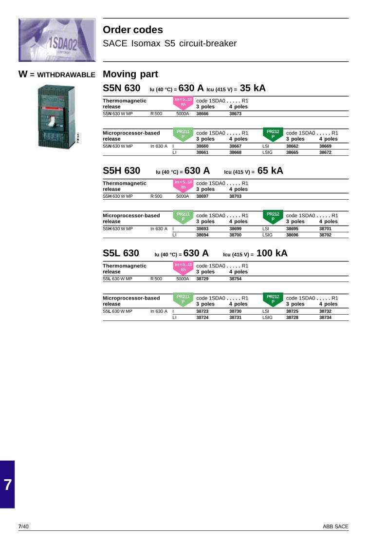
7/40
7
ABB SACE
PSIS9613
Moving partS5N 630 Iu (40 °C) = 630 A Icu (415 V) = 35 kAThermomagnetic code 1SDA0 . . . . . R1release 3 poles 4 polesS5N 630 W MP R 500 5000A 38666 38673
Microprocessor-based code 1SDA0 . . . . . R1 code 1SDA0 . . . . . R1release 3 poles 4 poles 3 poles 4 polesS5N 630 W MP In 630 A I 38660 38667 LSI 38662 38669
LI 38661 38668 LSIG 38665 38672
S5H 630 Iu (40 °C) = 630 A Icu (415 V) = 65 kAThermomagnetic code 1SDA0 . . . . . R1release 3 poles 4 polesS5H 630 W MP R 500 5000A 38697 38703
Microprocessor-based code 1SDA0 . . . . . R1 code 1SDA0 . . . . . R1release 3 poles 4 poles 3 poles 4 polesS5H 630 W MP In 630 A I 38693 38699 LSI 38695 38701
LI 38694 38700 LSIG 38696 38702
S5L 630 Iu (40 °C) = 630 A Icu (415 V) = 100 kAThermomagnetic code 1SDA0 . . . . . R1release 3 poles 4 polesS5L 630 W MP R 500 5000A 38729 38754
Microprocessor-based code 1SDA0 . . . . . R1 code 1SDA0 . . . . . R1release 3 poles 4 poles 3 poles 4 polesS5L 630 W MP In 630 A I 38723 38730 LSI 38725 38732
LI 38724 38731 LSIG 38728 38734
W = WITHDRAWABLE
Order codesSACE Isomax S5 circuit-breaker
Im = 5...10Ith
Im = 5...10Ith
Im = 5...10Ith
PR211P
PR212P
PR211P
PR212P
PR211P
PR212P
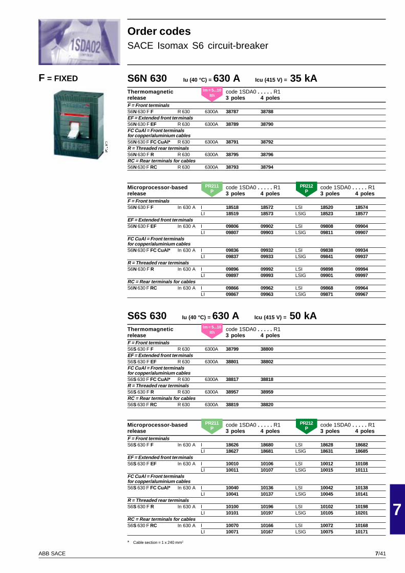
7/41
7
ABB SACE
PSIS9616
S6N 630 Iu (40 °C) = 630 A Icu (415 V) = 35 kAThermomagnetic code 1SDA0 . . . . . R1release 3 poles 4 polesF = Front terminalsS6N 630 F F R 630 6300A 38787 38788EF = Extended front te rminalsS6N 630 F EF R 630 6300A 38789 38790FC CuAl = Front terminalsfor copper/aluminium cablesS6N 630 F FC CuAl* R 630 6300A 38791 38792R = Threaded rear terminalsS6N 630 F R R 630 6300A 38795 38796RC = Rear terminals for cablesS6N 630 F RC R 630 6300A 38793 38794
Microprocessor-based code 1SDA0 . . . . . R1 code 1SDA0 . . . . . R1release 3 poles 4 poles 3 poles 4 polesF = Front terminalsS6N 630 F F In 630 A I 18518 18572 LSI 18520 18574
LI 18519 18573 LSIG 18523 18577EF = Extended front te rminalsS6N 630 F EF In 630 A I 09806 09902 LSI 09808 09904
LI 09807 09903 LSIG 09811 09907FC CuAl = Front terminalsfor copper/aluminium cablesS6N 630 F FC CuAl* In 630 A I 09836 09932 LSI 09838 09934
LI 09837 09933 LSIG 09841 09937R = Threaded rear terminalsS6N 630 F R In 630 A I 09896 09992 LSI 09898 09994
LI 09897 09993 LSIG 09901 09997RC = Rear terminals for cablesS6N 630 F RC In 630 A I 09866 09962 LSI 09868 09964
LI 09867 09963 LSIG 09871 09967
S6S 630 Iu (40 °C) = 630 A Icu (415 V) = 50 kAThermomagnetic code 1SDA0 . . . . . R1release 3 poles 4 polesF = Front terminalsS6S 630 F F R 630 6300A 38799 38800EF = Extended front te rminalsS6S 630 F EF R 630 6300A 38801 38802FC CuAl = Front terminalsfor copper/aluminium cablesS6S 630 F FC CuAl* R 630 6300A 38817 38818R = Threaded rear terminalsS6S 630 F R R 630 6300A 38957 38959RC = Rear terminals for cablesS6S 630 F RC R 630 6300A 38819 38820
Microprocessor-based code 1SDA0 . . . . . R1 code 1SDA0 . . . . . R1release 3 poles 4 poles 3 poles 4 polesF = Front terminalsS6S 630 F F In 630 A I 18626 18680 LSI 18628 18682
LI 18627 18681 LSIG 18631 18685EF = Extended front te rminalsS6S 630 F EF In 630 A I 10010 10106 LSI 10012 10108
LI 10011 10107 LSIG 10015 10111FC CuAl = Front terminalsfor copper/aluminium cablesS6S 630 F FC CuAl* In 630 A I 10040 10136 LSI 10042 10138
LI 10041 10137 LSIG 10045 10141R = Threaded rear terminalsS6S 630 F R In 630 A I 10100 10196 LSI 10102 10198
LI 10101 10197 LSIG 10105 10201RC = Rear terminals for cablesS6S 630 F RC In 630 A I 10070 10166 LSI 10072 10168
LI 10071 10167 LSIG 10075 10171
F = FIXED
Order codesSACE Isomax S6 circuit-breaker
* Cable section = 1 x 240 mm2
Im = 5...10Ith
Im = 5...10Ith
PR211P
PR212P
PR211P
PR212P
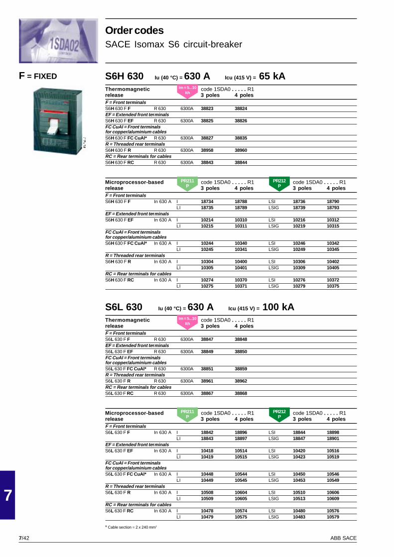
7/42
7
ABB SACE
PSIS9616
S6H 630 Iu (40 °C) = 630 A Icu (415 V) = 65 kAThermomagnetic code 1SDA0 . . . . . R1release 3 poles 4 polesF = Front terminalsS6H 630 F F R 630 6300A 38823 38824EF = Extended front te rminalsS6H 630 F EF R 630 6300A 38825 38826FC CuAl = Front terminalsfor copper/aluminium cablesS6H 630 F FC CuAl* R 630 6300A 38827 38835R = Threaded rear terminalsS6H 630 F R R 630 6300A 38958 38960RC = Rear terminals for cablesS6H 630 F RC R 630 6300A 38843 38844
Microprocessor-based code 1SDA0 . . . . . R1 code 1SDA0 . . . . . R1release 3 poles 4 poles 3 poles 4 polesF = Front terminalsS6H 630 F F In 630 A I 18734 18788 LSI 18736 18790
LI 18735 18789 LSIG 18739 18793EF = Extended front te rminalsS6H 630 F EF In 630 A I 10214 10310 LSI 10216 10312
LI 10215 10311 LSIG 10219 10315FC CuAl = Front terminalsfor copper/aluminium cablesS6H 630 F FC CuAl* In 630 A I 10244 10340 LSI 10246 10342
LI 10245 10341 LSIG 10249 10345R = Threaded rear terminalsS6H 630 F R In 630 A I 10304 10400 LSI 10306 10402
LI 10305 10401 LSIG 10309 10405RC = Rear terminals for cablesS6H 630 F RC In 630 A I 10274 10370 LSI 10276 10372
LI 10275 10371 LSIG 10279 10375
S6L 630 Iu (40 °C) = 630 A Icu (415 V) = 100 kAThermomagnetic code 1SDA0 . . . . . R1release 3 poles 4 polesF = Front terminalsS6L 630 F F R 630 6300A 38847 38848EF = Extended front te rminalsS6L 630 F EF R 630 6300A 38849 38850FC CuAl = Front terminalsfor copper/aluminium cablesS6L 630 F FC CuAl* R 630 6300A 38851 38859R = Threaded rear terminalsS6L 630 F R R 630 6300A 38961 38962RC = Rear terminals for cablesS6L 630 F RC R 630 6300A 38867 38868
Microprocessor-based code 1SDA0 . . . . . R1 code 1SDA0 . . . . . R1release 3 poles 4 poles 3 poles 4 polesF = Front terminalsS6L 630 F F In 630 A I 18842 18896 LSI 18844 18898
LI 18843 18897 LSIG 18847 18901EF = Extended front te rminalsS6L 630 F EF In 630 A I 10418 10514 LSI 10420 10516
LI 10419 10515 LSIG 10423 10519FC CuAl = Front terminalsfor copper/aluminium cablesS6L 630 F FC CuAl* In 630 A I 10448 10544 LSI 10450 10546
LI 10449 10545 LSIG 10453 10549R = Threaded rear terminalsS6L 630 F R In 630 A I 10508 10604 LSI 10510 10606
LI 10509 10605 LSIG 10513 10609RC = Rear terminals for cablesS6L 630 F RC In 630 A I 10478 10574 LSI 10480 10576
LI 10479 10575 LSIG 10483 10579
* Cable section = 2 x 240 mm2
F = FIXED
Order codesSACE Isomax S6 circuit-breaker
Im = 5...10Ith
Im = 5...10Ith
PR211P
PR212P
PR211P
PR212P
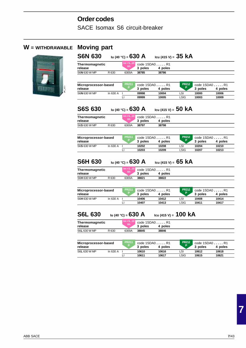
7/43
7
ABB SACE
PSIS9616
Moving partS6N 630 Iu (40 °C) = 630 A Icu (415 V) = 35 kAThermomagnetic code 1SDA0 . . . . . R1release 3 poles 4 polesS6N 630 W MP R 630 6300A 38785 38786
Microprocessor-based code 1SDA0 . . . . . R1 code 1SDA0 . . . . . R1release 3 poles 4 poles 3 poles 4 polesS6N 630 W MP In 630 A I 09998 10004 LSI 10000 10006
LI 09999 10005 LSIG 10003 10009
S6S 630 Iu (40 °C) = 630 A Icu (415 V) = 50 kAThermomagnetic code 1SDA0 . . . . . R1release 3 poles 4 polesS6S 630 W MP R 630 6300A 38797 38798
Microprocessor-based code 1SDA0 . . . . . R1 code 1SDA0 . . . . . R1release 3 poles 4 poles 3 poles 4 polesS6S 630 W MP In 630 A I 10202 10208 LSI 10204 10210
LI 10203 10209 LSIG 10207 10213
S6H 630 Iu (40 °C) = 630 A Icu (415 V) = 65 kAThermomagnetic code 1SDA0 . . . . . R1release 3 poles 4 polesS6H 630 W MP R 630 6300A 38821 38822
Microprocessor-based code 1SDA0 . . . . . R1 code 1SDA0 . . . . . R1release 3 poles 4 poles 3 poles 4 polesS6H 630 W MP In 630 A I 10406 10412 LSI 10408 10414
LI 10407 10413 LSIG 10411 10417
S6L 630 Iu (40 °C) = 630 A Icu (415 V) = 100 kAThermomagnetic code 1SDA0 . . . . . R1release 3 poles 4 polesS6L 630 W MP R 630 6300A 38845 38846
Microprocessor-based code 1SDA0 . . . . . R1 code 1SDA0 . . . . . R1release 3 poles 4 poles 3 poles 4 polesS6L 630 W MP In 630 A I 10610 10616 LSI 10612 10618
LI 10611 10617 LSIG 10615 10621
W = WITHDRAWABLE
Order codesSACE Isomax S6 circuit-breaker
Im = 5...10Ith
Im = 5...10Ith
Im = 5...10Ith
Im = 5...10Ith
PR211P
PR212P
PR211P
PR212P
PR211P
PR212P
PR211P
PR212P
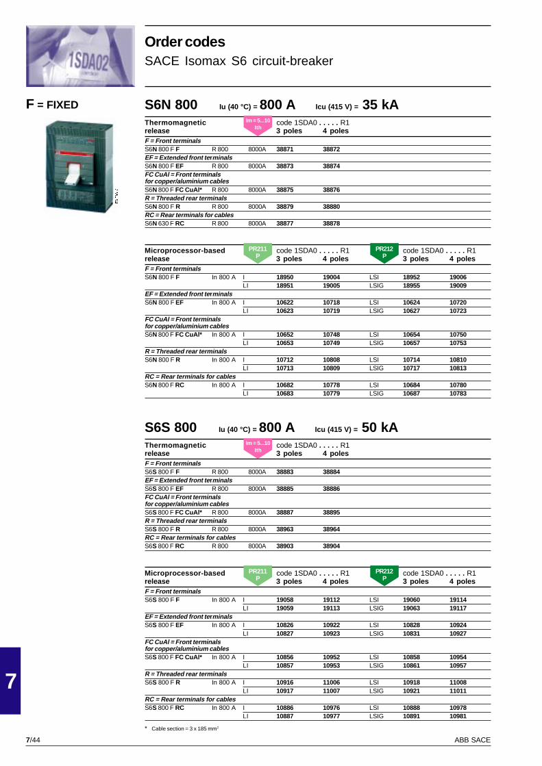
7/44
7
ABB SACE
PSIS9616
S6N 800 Iu (40 °C) = 800 A Icu (415 V) = 35 kAThermomagnetic code 1SDA0 . . . . . R1release 3 poles 4 polesF = Front terminalsS6N 800 F F R 800 8000A 38871 38872EF = Extended front te rminalsS6N 800 F EF R 800 8000A 38873 38874FC CuAl = Front terminalsfor copper/aluminium cablesS6N 800 F FC CuAl* R 800 8000A 38875 38876R = Threaded rear terminalsS6N 800 F R R 800 8000A 38879 38880RC = Rear terminals for cablesS6N 630 F RC R 800 8000A 38877 38878
Microprocessor-based code 1SDA0 . . . . . R1 code 1SDA0 . . . . . R1release 3 poles 4 poles 3 poles 4 polesF = Front terminalsS6N 800 F F In 800 A I 18950 19004 LSI 18952 19006
LI 18951 19005 LSIG 18955 19009EF = Extended front te rminalsS6N 800 F EF In 800 A I 10622 10718 LSI 10624 10720
LI 10623 10719 LSIG 10627 10723FC CuAl = Front terminalsfor copper/aluminium cablesS6N 800 F FC CuAl* In 800 A I 10652 10748 LSI 10654 10750
LI 10653 10749 LSIG 10657 10753R = Threaded rear terminalsS6N 800 F R In 800 A I 10712 10808 LSI 10714 10810
LI 10713 10809 LSIG 10717 10813RC = Rear terminals for cablesS6N 800 F RC In 800 A I 10682 10778 LSI 10684 10780
LI 10683 10779 LSIG 10687 10783
S6S 800 Iu (40 °C) = 800 A Icu (415 V) = 50 kAThermomagnetic code 1SDA0 . . . . . R1release 3 poles 4 polesF = Front terminalsS6S 800 F F R 800 8000A 38883 38884EF = Extended front te rminalsS6S 800 F EF R 800 8000A 38885 38886FC CuAl = Front terminalsfor copper/aluminium cablesS6S 800 F FC CuAl* R 800 8000A 38887 38895R = Threaded rear terminalsS6S 800 F R R 800 8000A 38963 38964RC = Rear terminals for cablesS6S 800 F RC R 800 8000A 38903 38904
Microprocessor-based code 1SDA0 . . . . . R1 code 1SDA0 . . . . . R1release 3 poles 4 poles 3 poles 4 polesF = Front terminalsS6S 800 F F In 800 A I 19058 19112 LSI 19060 19114
LI 19059 19113 LSIG 19063 19117EF = Extended front te rminalsS6S 800 F EF In 800 A I 10826 10922 LSI 10828 10924
LI 10827 10923 LSIG 10831 10927FC CuAl = Front terminalsfor copper/aluminium cablesS6S 800 F FC CuAl* In 800 A I 10856 10952 LSI 10858 10954
LI 10857 10953 LSIG 10861 10957R = Threaded rear terminalsS6S 800 F R In 800 A I 10916 11006 LSI 10918 11008
LI 10917 11007 LSIG 10921 11011RC = Rear terminals for cablesS6S 800 F RC In 800 A I 10886 10976 LSI 10888 10978
LI 10887 10977 LSIG 10891 10981
* Cable section = 3 x 185 mm2
F = FIXED
Order codesSACE Isomax S6 circuit-breaker
Im = 5...10Ith
Im = 5...10Ith
PR211P
PR212P
PR211P
PR212P

7/45
7
ABB SACE
PSIS9616
S6L 800 Iu (40 °C) = 800 A Icu (415 V) = 100 kAThermomagnetic code 1SDA0 . . . . . R1release 3 poles 4 polesF = Front terminalsS6L 800 F F R 800 8000A 38931 38932EF = Extended front te rminalsS6L 800 F EF R 800 8000A 38933 38934FC CuAl = Front terminalsfor copper/aluminium cablesS6L 800 F FC CuAl* R 800 8000A 38935 38943R = Threaded rear terminalsS6L 800 F R R 800 8000A 38973 38974RC = Rear terminals for cablesS6L 800 F RC R 800 8000A 38951 38952
Microprocessor-based code 1SDA0 . . . . . R1 code 1SDA0 . . . . . R1release 3 poles 4 poles 3 poles 4 polesF = Front terminalsS6L 800 F F In 800 A I 19274 19328 LSI 19276 19330
LI 19275 19329 LSIG 19279 19333EF = Extended front te rminalsS6L 800 F EF In 800 A I 11228 11324 LSI 11230 11326
LI 11229 11325 LSIG 11233 11329FC CuAl = Front terminalsfor copper/aluminium cablesS6L 800 F FC CuAl* In 800 A I 11258 11354 LSI 11260 11356
LI 11259 11355 LSIG 11263 11359R = Threaded rear terminalsS6L 800 F R In 800 A I 11318 11414 LSI 11320 11416
LI 11319 11415 LSIG 11323 11419RC = Rear terminals for cablesS6L 800 F RC In 800 A I 11288 11384 LSI 11290 11386
LI 11289 11385 LSIG 11293 11389
S6H 800 Iu (40 °C) = 800 A Icu (415 V) = 65 kAThermomagnetic code 1SDA0 . . . . . R1release 3 poles 4 polesF = Front terminalsS6H 800 F F R 800 8000A 38907 38908EF = Extended front te rminalsS6H 800 F EF R 800 8000A 38909 38910FC CuAl = Front terminalsfor copper/aluminium cablesS6H 800 F FC CuAl* R 800 8000A 38911 38919R = Threaded rear terminalsS6H 800 F R R 800 8000A 38965 38966RC = Rear terminals for cablesS6H 800 F RC R 800 8000A 38927 38928
Microprocessor-based code 1SDA0 . . . . . R1 code 1SDA0 . . . . . R1release 3 poles 4 poles 3 poles 4 polesF = Front terminalsS6H 800 F F In 800 A I 19166 19220 LSI 19168 19222
LI 19167 19221 LSIG 19171 19225EF = Extended front te rminalsS6H 800 F EF In 800 A I 11024 11120 LSI 11026 11122
LI 11025 11121 LSIG 11029 11125FC CuAl = Front terminalsfor copper/aluminium cablesS6H 800 F FC CuAl* In 800 A I 11054 11150 LSIG 11056 11152
LI 11055 11151 LSIG 11059 11155R = Threaded rear terminalsS6H 800 F R In 800 A I 11114 11210 LSIG 11116 11212
LI 11115 11211 LSIG 11119 11215RC = Rear terminals for cablesS6H 800 F RC In 800 A I 11084 11180 LSI 11086 11182
LI 11085 11181 LSIG 11089 11185
Order codesSACE Isomax S6 circuit-breaker
F = FIXED
* Cable section = 3 x 185 mm2
Im = 5...10Ith
Im = 5...10Ith
PR211P
PR212P
PR211P
PR212P

7/46
7
ABB SACE
PSIS9616
Moving partS6N 800 Iu (40 °C) = 800 A Icu (415 V) = 35 kAThermomagnetic code 1SDA0 . . . . . R1release 3 poles 4 polesS6N 800 W MP R 800 8000A 38869 38870
Microprocessor-based code 1SDA0 . . . . . R1 code 1SDA0 . . . . . R1release 3 poles 4 poles 3 poles 4 polesS6N 800 W MP In 800 A I 10814 10820 LSI 10816 10822
LI 10815 10821 LSIG 10819 10825
S6S 800 Iu (40 °C) = 800 A Icu (415 V) = 50 kAThermomagnetic code 1SDA0 . . . . . R1release 3 poles 4 polesS6S 800 W MP R 800 8000A 38881 38882
Microprocessor-based code 1SDA0 . . . . . R1 code 1SDA0 . . . . . R1release 3 poles 4 poles 3 poles 4 polesS6S 800 W MP In 800 A I 11012 11018 LSI 11014 11020
LI 11013 11019 LSIG 11017 11023
S6H 800 Iu (40 °C) = 800 A Icu (415 V) = 65 kAThermomagnetic code 1SDA0 . . . . . R1release 3 poles 4 polesS6H 800 W MP R 800 8000A 38905 38906
Microprocessor-based code 1SDA0 . . . . . R1 code 1SDA0 . . . . . R1release 3 poles 4 poles 3 poles 4 polesS6H 800 W MP In 800 A I 11216 11222 LSI 11218 11224
LI 11217 11223 LSIG 11221 11227
S6L 800 Iu (40 °C) = 800 A Icu (415 V) = 100 kAThermomagnetic code 1SDA0 . . . . . R1release 3 poles 4 polesS6L 800 W MP R 800 8000A 38929 38930
Microprocessor-based code 1SDA0 . . . . . R1 code 1SDA0 . . . . . R1release 3 poles 4 poles 3 poles 4 polesS6L 800 W MP In 800 A I 11420 11682 LSI 11422 11684
LI 11421 11683 LSIG 11425 11687
W = WITHDRAWABLE
Order codesSACE Isomax S6 circuit-breaker
Im = 5...10Ith
Im = 5...10Ith
Im = 5...10Ith
Im = 5...10Ith
PR211P
PR212P
PR211P
PR212P
PR211P
PR212P
PR211P
PR212P

7/47
7
ABB SACE
PSIS9620
S7S 1250 Iu (40 °C) = 1250 A Icu (415 V) = 50 kAMicroprocessor-based code 1SDA0 . . . . . R1 code 1SDA0 . . . . . R1release 3 poles 4 poles 3 poles 4 polesF = Front terminalsS7S 1250 F F In 1000 A I 19382 19490 LSI 19386 19494
LI 19384 19492 LSIG 19392 19500S7S 1250 F F In 1250 A I 19383 19491 LSI 19387 19495
LI 19385 19493 LSIG 19393 19501EF = Extended front te rminalsS7S 1250 F EF In 1000 A I 11432 11624 LSI 11436 11628
LI 11434 11626 LSIG 11442 11634S7S 1250 F EF In 1250 A I 11433 11625 LSI 11437 11629
LI 11435 11627 LSIG 11443 11635FC CuAl = Front terminalsfor copper/aluminium cablesS7S 1250 F FC CuAl In 1000 A I 11492 11428 LSI 11496 11688
LI 11494 11430 LSIG 11502 11694S7S 1250 F FC CuAl In 1250 A I 11493 11429 LSI 11497 11689
LI 11495 11431 LSIG 11503 11695VR = Vertical flat-barrear terminalsS7S 1250 F VR In 1000 A I 11612 11804 LSI 11616 11808
LI 11614 11806 LSIG 11622 11814S7S 1250 F VR In 1250 A I 11613 11805 LSI 11617 11809
LI 11615 11807 LSIG 11623 11815HR = Horizontal flat-barrear terminalsS7S 1250 F HR In 1000 A I 11552 11744 LSI 11556 11748
LI 11554 11746 LSIG 11562 11754S7S 1250 F HR In 1250 A I 11553 11745 LSI 11557 11749
LI 11555 11747 LSIG 11563 11755
S7H 1250 Iu (40 °C) = 1250 A Icu (415 V) = 65 kAMicroprocessor-based code 1SDA0 . . . . . R1 code 1SDA0 . . . . . R1release 3 poles 4 poles 3 poles 4 polesF = Front terminalsS7H 1250 F F In 1000 A I 19598 19706 LSI 19602 19710
LI 19600 19708 LSIG 19608 19716S7H 1250 F F In 1250 A I 19599 19707 LSI 19603 19711
LI 19601 19709 LSIG 19609 19717EF = Extended front te rminalsS7H 1250 F EF In 1000 A I 11840 12032 LSI 11844 12036
LI 11842 12034 LSIG 11850 12042S7H 1250 F EF In 1250 A I 11841 12033 LSI 11845 12037
LI 11843 12035 LSIG 11851 12043FC CuAl = Front terminalsfor copper/aluminium cablesS7H 1250 F FC CuAl In 1000 A I 11900 12092 LSI 11904 12096
LI 11902 12094 LSIG 11910 12102S7H 1250 F FC CuAl In 1250 A I 11901 12093 LSI 11905 12097
LI 11903 12095 LSIG 11911 12103VR = Vertical flat-barrear terminalsS7H 1250 F VR In 1000 A I 12020 12212 LSI 12024 12216
LI 12022 12214 LSIG 12030 12222S7H 1250 F VR In 1250 A I 12021 12213 LSI 12025 12217
LI 12023 12215 LSIG 12031 12223HR = Horizontal flat-barrear terminalsS7H 1250 F HR In 1000 A I 11960 12152 LSI 11964 12156
LI 11962 12154 LSIG 11970 12162S7H 1250 F HR In 1250 A I 11961 12153 LSI 11965 12157
LI 11963 12155 LSIG 11971 12163
Order codesSACE Isomax S7 circuit-breaker
F = FIXEDPR211
PPR212
P
PR211P
PR212P

7/48
7
ABB SACE
PSIS9620
PSIS9620
S7L 1250 Iu (40 °C) = 1250 A Icu (415 V) = 100 kAMicroprocessor-based code 1SDA0 . . . . . R1 code 1SDA0 . . . . . R1release 3 poles 4 poles 3 poles 4 polesF = Front terminalsS7L 1250 F F In 1000 A I 19814 19922 LSI 19818 19926
LI 19816 19924 LSIG 19824 19932S7L 1250 F F In 1250 A I 19815 19923 LSI 19819 19927
LI 19817 19925 LSIG 19825 19933EF = Extended front te rminalsS7L 1250 F EF In 1000 A I 12248 12440 LSI 12252 12444
LI 12250 12442 LSIG 12258 12450S7L 1250 F EF In 1250 A I 12249 12441 LSI 12253 12445
LI 12251 12443 LSIG 12259 12451FC CuAl = Front terminalsfor copper/aluminium cablesS7L 1250 F FC CuAl In 1000 A I 12308 12500 LSI 12312 12504
LI 12310 12502 LSIG 12318 12510S7L 1250 F FC CuAl In 1250 A I 12309 12501 LSI 12313 12505
LI 12311 12503 LSIG 12319 12511VR = Vertical flat-barrear terminalsS7L 1250 F VR In 1000 A I 12428 12620 LSI 12432 12624
LI 12430 12622 LSIG 12438 12630S7L 1250 F VR In 1250 A I 12429 12621 LSI 12433 12625
LI 12431 12623 LSIG 12439 12631HR = Horizontal flat-barrear terminalsS7L 1250 F HR In 1000 A I 12368 12560 LSI 12372 12564
LI 12370 12562 LSIG 12378 12570S7L 1250 F HR In 1250 A I 12369 12561 LSI 12373 12565
LI 12371 12563 LSIG 12379 12571
Moving partS7S 1250 Iu (40 °C) = 1250 A Icu (415 V) = 50 kAMicroprocessor-based code 1SDA0 . . . . . R1 code 1SDA0 . . . . . R1release 3 poles 4 poles 3 poles 4 polesS7S 1250 W MP In 1000 A I 11816 11828 LSI 11820 11832
LI 11818 11830 LSIG 11826 11838S7S 1250 W MP In 1250 A I 11817 11829 LSI 11821 11833
LI 11819 11831 LSIG 11827 11839
S7H 1250 Iu (40 °C) = 1250 A Icu (415 V) = 65 kAMicroprocessor-based code 1SDA0 . . . . . R1 code 1SDA0 . . . . . R1release 3 poles 4 poles 3 poles 4 polesS7H 1250 W MP In 1000 A I 12224 12236 LSI 12228 12240
LI 12226 12238 LSIG 12234 12246S7H 1250 W MP In 1250 A I 12225 12237 LSI 12229 12241
LI 12227 12239 LSIG 12235 12247
S7L 1250 Iu (40 °C) = 1250 A Icu (415 V) = 100 kAMicroprocessor-based code 1SDA0 . . . . . R1 code 1SDA0 . . . . . R1release 3 poles 4 poles 3 poles 4 polesS7L 1250 W MP In 1000 A I 12632 12644 LSI 12636 12648
LI 12634 12646 LSIG 12642 12654S7L 1250 W MP In 1250 A I 12633 12645 LSI 12637 12649
LI 12635 12647 LSIG 12643 12655
W = WITHDRAWABLE
F = FIXED
Order codesSACE Isomax S7 circuit-breaker
PR211P
PR212P
PR211P
PR212P
PR211P
PR212P
PR211P
PR212P
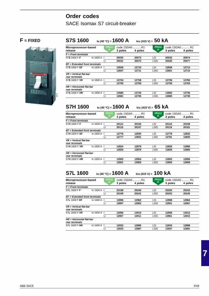
7/49
7
ABB SACE
PSIS9620
S7S 1600 Iu (40 °C) = 1600 A Icu (415 V) = 50 kAMicroprocessor-based code 1SDA0 . . . . . R1 code 1SDA0 . . . . . R1release 3 poles 4 poles 3 poles 4 polesF = Front terminalsS7S 1600 F F In 1600 A I 20030 20072 LSI 20032 20074
LI 20031 20073 LSIG 20035 20077EF = Extended front terminalsS7S 1600 F EF In 1600 A I 12656 12710 LSI 12658 12712
LI 12657 12711 LSIG 12661 12715VR = Vertical flat-barrear terminalsS7S 1600 F VR In 1600 A I 12704 12758 LSI 12706 12760
LI 12705 12759 LSIG 12709 12763HR = Horizontal flat-barrear terminalsS7S 1600 F HR In 1600 A I 12680 12734 LSI 12682 12736
LI 12681 12735 LSIG 12685 12739
S7H 1600 Iu (40 °C) = 1600 A Icu (415 V) = 65 kAMicroprocessor-based code 1SDA0 . . . . . R1 code 1SDA0 . . . . . R1release 3 poles 4 poles 3 poles 4 polesF = Front terminalsS7H 1600 F F In 1600 A I 20114 20156 LSI 20116 20158
LI 20115 20157 LSIG 20119 20161EF = Extended front terminalsS7H 1600 F EF In 1600 A I 12776 12830 LSI 12778 12832
LI 12777 12831 LSIG 12781 12835VR = Vertical flat-barrear terminalsS7H 1600 F VR In 1600 A I 12824 12878 LSI 12826 12880
LI 12825 12879 LSIG 12829 12883HR = Horizontal flat-barrear terminalsS7H 1600 F HR In 1600 A I 12800 12854 LSI 12802 12856
LI 12801 12855 LSIG 12805 12859
S7L 1600 Iu (40 °C) = 1600 A Icu (415 V) = 100 kAMicroprocessor-based code 1SDA0 . . . . . R1 code 1SDA0 . . . . . R1release 3 poles 4 poles 3 poles 4 polesF = Front terminalsS7L 1600 F F In 1600 A I 20198 20240 LSI 20200 20242
LI 20199 20241 LSIG 20203 20245EF = Extended front terminalsS7L 1600 F EF In 1600 A I 12896 12962 LSI 12898 12964
LI 12897 12963 LSIG 12901 12967VR = Vertical flat-barrear terminalsS7L 1600 F VR In 1600 A I 12956 13010 LSI 12958 13012
LI 12957 13011 LSIG 12961 13015HR = Horizontal flat-barrear terminalsS7L 1600 F HR In 1600 A I 12932 12986 LSI 12934 12988
LI 12933 12987 LSIG 12937 12991
Order codesSACE Isomax S7 circuit-breaker
F = FIXED
PR211P
PR212P
PR211P
PR212P
PR211P
PR212P
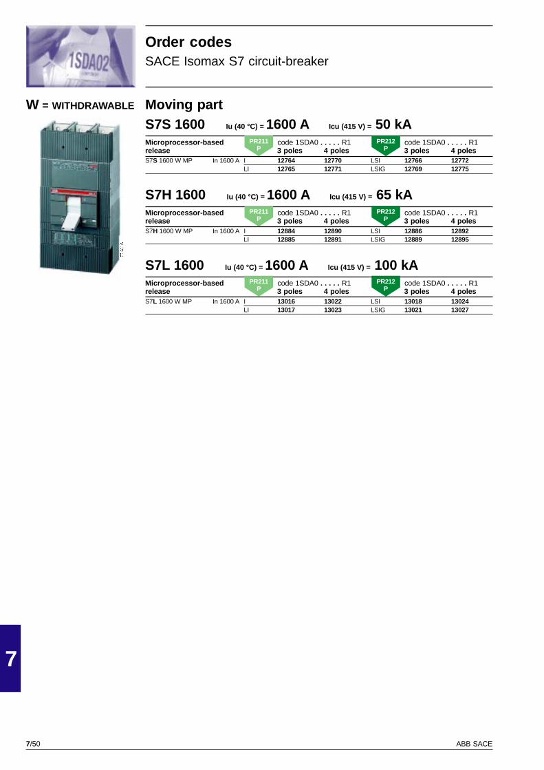
7/50
7
ABB SACE
PSIS9620
Moving partS7S 1600 Iu (40 °C) = 1600 A Icu (415 V) = 50 kAMicroprocessor-based code 1SDA0 . . . . . R1 code 1SDA0 . . . . . R1release 3 poles 4 poles 3 poles 4 polesS7S 1600 W MP In 1600 A I 12764 12770 LSI 12766 12772
LI 12765 12771 LSIG 12769 12775
S7H 1600 Iu (40 °C) = 1600 A Icu (415 V) = 65 kAMicroprocessor-based code 1SDA0 . . . . . R1 code 1SDA0 . . . . . R1release 3 poles 4 poles 3 poles 4 polesS7H 1600 W MP In 1600 A I 12884 12890 LSI 12886 12892
LI 12885 12891 LSIG 12889 12895
S7L 1600 Iu (40 °C) = 1600 A Icu (415 V) = 100 kAMicroprocessor-based code 1SDA0 . . . . . R1 code 1SDA0 . . . . . R1release 3 poles 4 poles 3 poles 4 polesS7L 1600 W MP In 1600 A I 13016 13022 LSI 13018 13024
LI 13017 13023 LSIG 13021 13027
W = WITHDRAWABLE
Order codesSACE Isomax S7 circuit-breaker
PR211P
PR212P
PR211P
PR212P
PR211P
PR212P
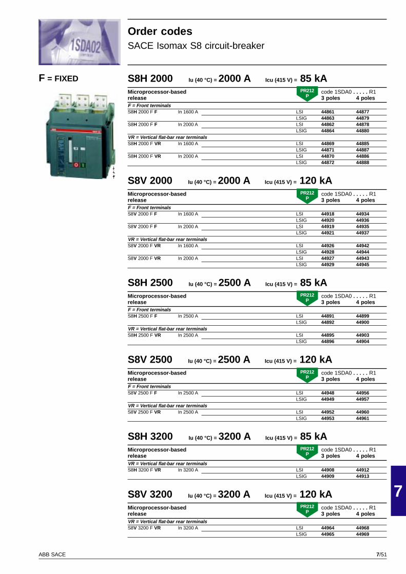
7/51
7
ABB SACE
GSIS9018
S8H 2000 Iu (40 °C) = 2000 A Icu (415 V) = 85 kAMicroprocessor-based code 1SDA0 . . . . . R1release 3 poles 4 polesF = Front terminalsS8H 2000 F F In 1600 A LSI 44861 44877
LSIG 44863 44879S8H 2000 F F In 2000 A LSI 44862 44878
LSIG 44864 44880VR = Vertical flat-bar rear terminalsS8H 2000 F VR In 1600 A LSI 44869 44885
LSIG 44871 44887S8H 2000 F VR In 2000 A LSI 44870 44886
LSIG 44872 44888
S8V 2000 Iu (40 °C) = 2000 A Icu (415 V) = 120 kAMicroprocessor-based code 1SDA0 . . . . . R1release 3 poles 4 polesF = Front terminalsS8V 2000 F F In 1600 A LSI 44918 44934
LSIG 44920 44936S8V 2000 F F In 2000 A LSI 44919 44935
LSIG 44921 44937VR = Vertical flat-bar rear terminalsS8V 2000 F VR In 1600 A LSI 44926 44942
LSIG 44928 44944S8V 2000 F VR In 2000 A LSI 44927 44943
LSIG 44929 44945
S8H 2500 Iu (40 °C) = 2500 A Icu (415 V) = 85 kAMicroprocessor-based code 1SDA0 . . . . . R1release 3 poles 4 polesF = Front terminalsS8H 2500 F F In 2500 A LSI 44891 44899
LSIG 44892 44900VR = Vertical flat-bar rear terminalsS8H 2500 F VR In 2500 A LSI 44895 44903
LSIG 44896 44904
S8V 2500 Iu (40 °C) = 2500 A Icu (415 V) = 120 kAMicroprocessor-based code 1SDA0 . . . . . R1release 3 poles 4 polesF = Front terminalsS8V 2500 F F In 2500 A LSI 44948 44956
LSIG 44949 44957VR = Vertical flat-bar rear terminalsS8V 2500 F VR In 2500 A LSI 44952 44960
LSIG 44953 44961
S8H 3200 Iu (40 °C) = 3200 A Icu (415 V) = 85 kAMicroprocessor-based code 1SDA0 . . . . . R1release 3 poles 4 polesVR = Vertical flat-bar rear terminalsS8H 3200 F VR In 3200 A LSI 44908 44912
LSIG 44909 44913
S8V 3200 Iu (40 °C) = 3200 A Icu (415 V) = 120 kAMicroprocessor-based code 1SDA0 . . . . . R1release 3 poles 4 polesVR = Vertical flat-bar rear terminalsS8V 3200 F VR In 3200 A LSI 44964 44968
LSIG 44965 44969
F = FIXED
Order codesSACE Isomax S8 circuit-breaker
PR212P
PR212P
PR212P
PR212P
PR212P
PR212P
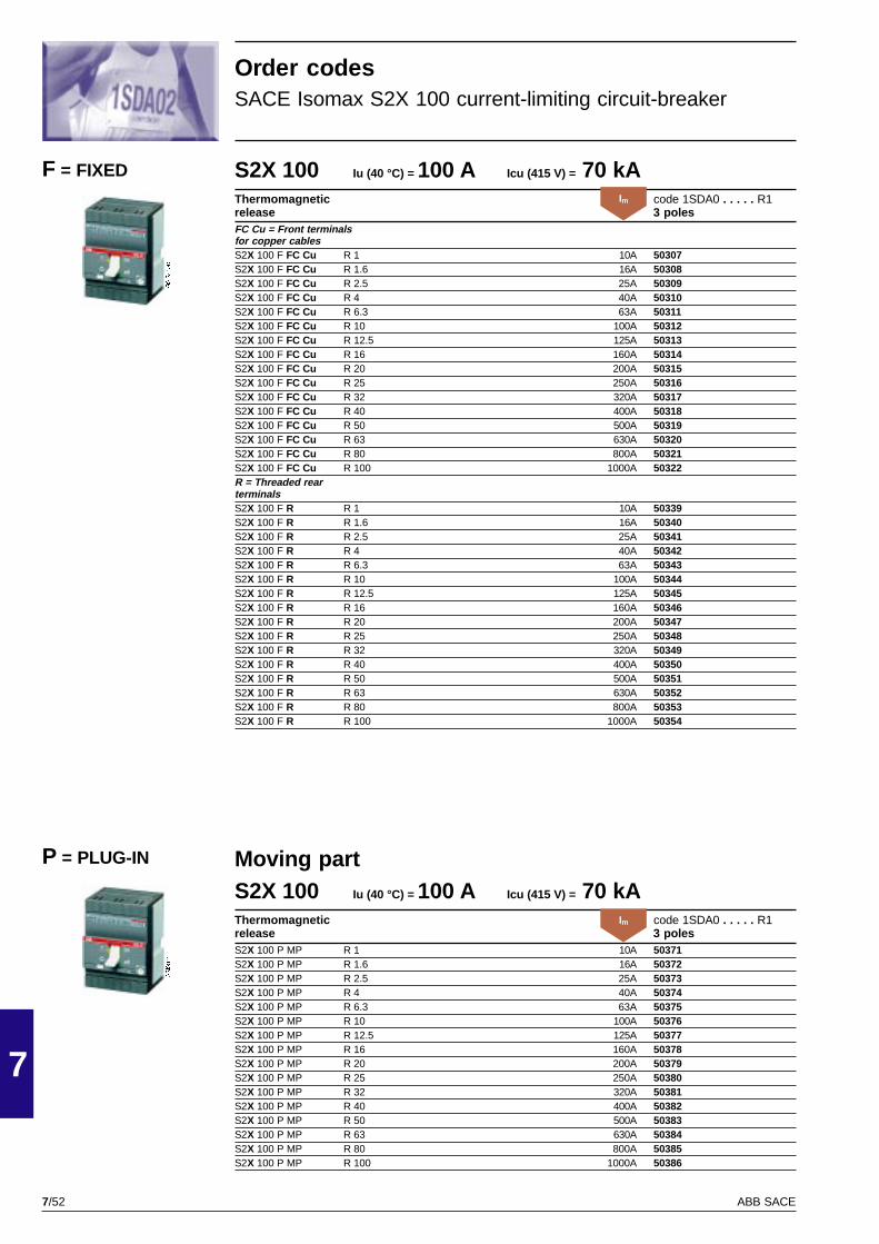
7/52
7
ABB SACE
GSIS9150
GSIS9150
Moving partS2X 100 Iu (40 °C) = 100 A Icu (415 V) = 70 kAThermomagnetic code 1SDA0 . . . . . R1release 3 polesS2X 100 P MP R 1 10A 50371S2X 100 P MP R 1.6 16A 50372S2X 100 P MP R 2.5 25A 50373S2X 100 P MP R 4 40A 50374S2X 100 P MP R 6.3 63A 50375S2X 100 P MP R 10 100A 50376S2X 100 P MP R 12.5 125A 50377S2X 100 P MP R 16 160A 50378S2X 100 P MP R 20 200A 50379S2X 100 P MP R 25 250A 50380S2X 100 P MP R 32 320A 50381S2X 100 P MP R 40 400A 50382S2X 100 P MP R 50 500A 50383S2X 100 P MP R 63 630A 50384S2X 100 P MP R 80 800A 50385S2X 100 P MP R 100 1000A 50386
P = PLUG-IN
S2X 100 Iu (40 °C) = 100 A Icu (415 V) = 70 kAThermomagnetic code 1SDA0 . . . . . R1release 3 polesFC Cu = Front terminalsfor copper cablesS2X 100 F FC Cu R 1 10A 50307S2X 100 F FC Cu R 1.6 16A 50308S2X 100 F FC Cu R 2.5 25A 50309S2X 100 F FC Cu R 4 40A 50310S2X 100 F FC Cu R 6.3 63A 50311S2X 100 F FC Cu R 10 100A 50312S2X 100 F FC Cu R 12.5 125A 50313S2X 100 F FC Cu R 16 160A 50314S2X 100 F FC Cu R 20 200A 50315S2X 100 F FC Cu R 25 250A 50316S2X 100 F FC Cu R 32 320A 50317S2X 100 F FC Cu R 40 400A 50318S2X 100 F FC Cu R 50 500A 50319S2X 100 F FC Cu R 63 630A 50320S2X 100 F FC Cu R 80 800A 50321S2X 100 F FC Cu R 100 1000A 50322R = Threaded rearterminalsS2X 100 F R R 1 10A 50339S2X 100 F R R 1.6 16A 50340S2X 100 F R R 2.5 25A 50341S2X 100 F R R 4 40A 50342S2X 100 F R R 6.3 63A 50343S2X 100 F R R 10 100A 50344S2X 100 F R R 12.5 125A 50345S2X 100 F R R 16 160A 50346S2X 100 F R R 20 200A 50347S2X 100 F R R 25 250A 50348S2X 100 F R R 32 320A 50349S2X 100 F R R 40 400A 50350S2X 100 F R R 50 500A 50351S2X 100 F R R 63 630A 50352S2X 100 F R R 80 800A 50353S2X 100 F R R 100 1000A 50354
Order codesSACE Isomax S2X 100 current-limiting circuit-breaker
F = FIXEDIm
Im
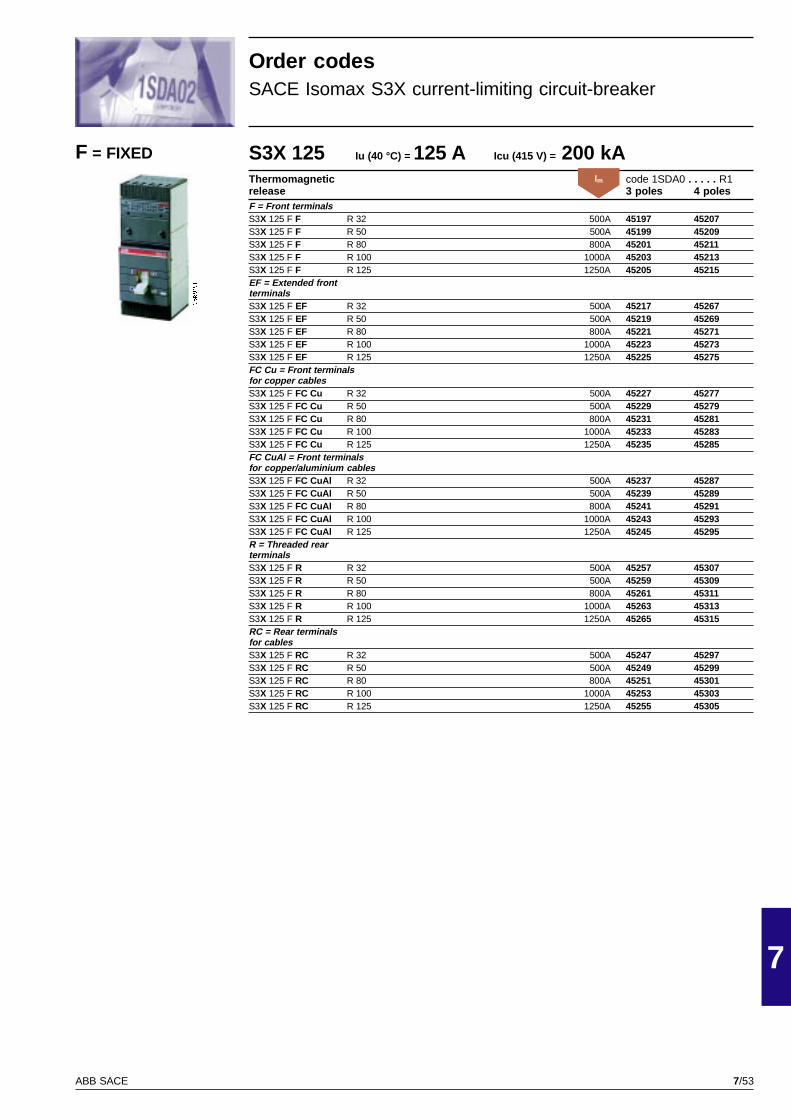
7/53
7
ABB SACE
GSIS9151
S3X 125 Iu (40 °C) = 125 A Icu (415 V) = 200 kAThermomagnetic code 1SDA0 . . . . . R1release 3 poles 4 polesF = Front terminalsS3X 125 F F R 32 500A 45197 45207S3X 125 F F R 50 500A 45199 45209S3X 125 F F R 80 800A 45201 45211S3X 125 F F R 100 1000A 45203 45213S3X 125 F F R 125 1250A 45205 45215EF = Extended frontterminalsS3X 125 F EF R 32 500A 45217 45267S3X 125 F EF R 50 500A 45219 45269S3X 125 F EF R 80 800A 45221 45271S3X 125 F EF R 100 1000A 45223 45273S3X 125 F EF R 125 1250A 45225 45275FC Cu = Front terminalsfor copper cablesS3X 125 F FC Cu R 32 500A 45227 45277S3X 125 F FC Cu R 50 500A 45229 45279S3X 125 F FC Cu R 80 800A 45231 45281S3X 125 F FC Cu R 100 1000A 45233 45283S3X 125 F FC Cu R 125 1250A 45235 45285FC CuAl = Front terminalsfor copper/aluminium cablesS3X 125 F FC CuAl R 32 500A 45237 45287S3X 125 F FC CuAl R 50 500A 45239 45289S3X 125 F FC CuAl R 80 800A 45241 45291S3X 125 F FC CuAl R 100 1000A 45243 45293S3X 125 F FC CuAl R 125 1250A 45245 45295R = Threaded rearterminalsS3X 125 F R R 32 500A 45257 45307S3X 125 F R R 50 500A 45259 45309S3X 125 F R R 80 800A 45261 45311S3X 125 F R R 100 1000A 45263 45313S3X 125 F R R 125 1250A 45265 45315RC = Rear terminalsfor cablesS3X 125 F RC R 32 500A 45247 45297S3X 125 F RC R 50 500A 45249 45299S3X 125 F RC R 80 800A 45251 45301S3X 125 F RC R 100 1000A 45253 45303S3X 125 F RC R 125 1250A 45255 45305
F = FIXED
Order codesSACE Isomax S3X current-limiting circuit-breaker
Im
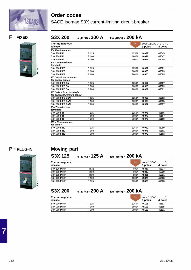
7/54
7
ABB SACE
GSIS9151
GSIS9151
Moving partS3X 125 Iu (40 °C) = 125 A Icu (415 V) = 200 kAThermomagnetic code 1SDA0 . . . . . R1release 3 poles 4 polesS3X 125 P MP R 32 500A 45317 45327S3X 125 P MP R 50 500A 45319 45329S3X 125 P MP R 80 800A 45321 45331S3X 125 P MP R 100 1000A 45323 45333S3X 125 P MP R 125 1250A 45325 45335
S3X 200 Iu (40 °C) = 200 A Icu (415 V) = 200 kAThermomagnetic code 1SDA0 . . . . . R1release 3 poles 4 polesS3X 200 P MP R 125 1250A 46111 46117S3X 200 P MP R 160 1600A 46113 46119S3X 200 P MP R 200 2000A 46115 46121
P = PLUG-IN
S3X 200 Iu (40 °C) = 200 A Icu (415 V) = 200 kAThermomagnetic code 1SDA0 . . . . . R1release 3 poles 4 polesF = Front terminalsS3X 200 F F R 125 1250A 46039 46045S3X 200 F F R 160 1600A 46041 46047S3X 200 F F R 200 2000A 46043 46049EF = Extended frontterminalsS3X 200 F EF R 125 1250A 46051 46081S3X 200 F EF R 160 1600A 46053 46083S3X 200 F EF R 200 2000A 46055 46085FC Cu = Front terminalsfor copper cablesS3X 200 F FC Cu R 125 1250A 46057 46087S3X 200 F FC Cu R 160 1600A 46059 46089S3X 200 F FC Cu R 200 2000A 46061 46091FC CuAl = Front terminalsfor copper/aluminium cablesS3X 200 F FC CuAl R 125 1250A 46063 46093S3X 200 F FC CuAl R 160 1600A 46065 46095S3X 200 F FC CuAl R 200 2000A 46067 46097R = Threaded rearterminalsS3X 200 F R R 125 1250A 46075 46105S3X 200 F R R 160 1600A 46077 46107S3X 200 F R R 200 2000A 46079 46109RC = Rear terminalsfor cablesS3X 200 F RC R 125 1250A 46069 46099S3X 200 F RC R 160 1600A 46071 46101S3X 200 F RC R 200 2000A 46073 46103
F = FIXED
Order codesSACE Isomax S3X current-limiting circuit-breaker
Im
Im
Im
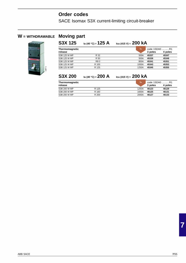
7/55
7
ABB SACE
GSIS9151
Moving partS3X 125 Iu (40 °C) = 125 A Icu (415 V) = 200 kAThermomagnetic code 1SDA0 . . . . . R1release 3 poles 4 polesS3X 125 W MP R 32 500A 45337 45347S3X 125 W MP R 50 500A 45339 45349S3X 125 W MP R8 0 800A 45341 45351S3X 125 W MP R 100 1000A 45343 45353S3X 125 W MP R 125 1250A 45345 45355
S3X 200 Iu (40 °C) = 200 A Icu (415 V) = 200 kAThermomagnetic code 1SDA0 . . . . . R1release 3 poles 4 polesS3X 200 W MP R 125 1250A 46123 46129S3X 200 W MP R 160 1600A 46125 46131S3X 200 W MP R 200 2000A 46127 46133
W = WITHDRAWABLE
Order codesSACE Isomax S3X current-limiting circuit-breaker
Im
Im
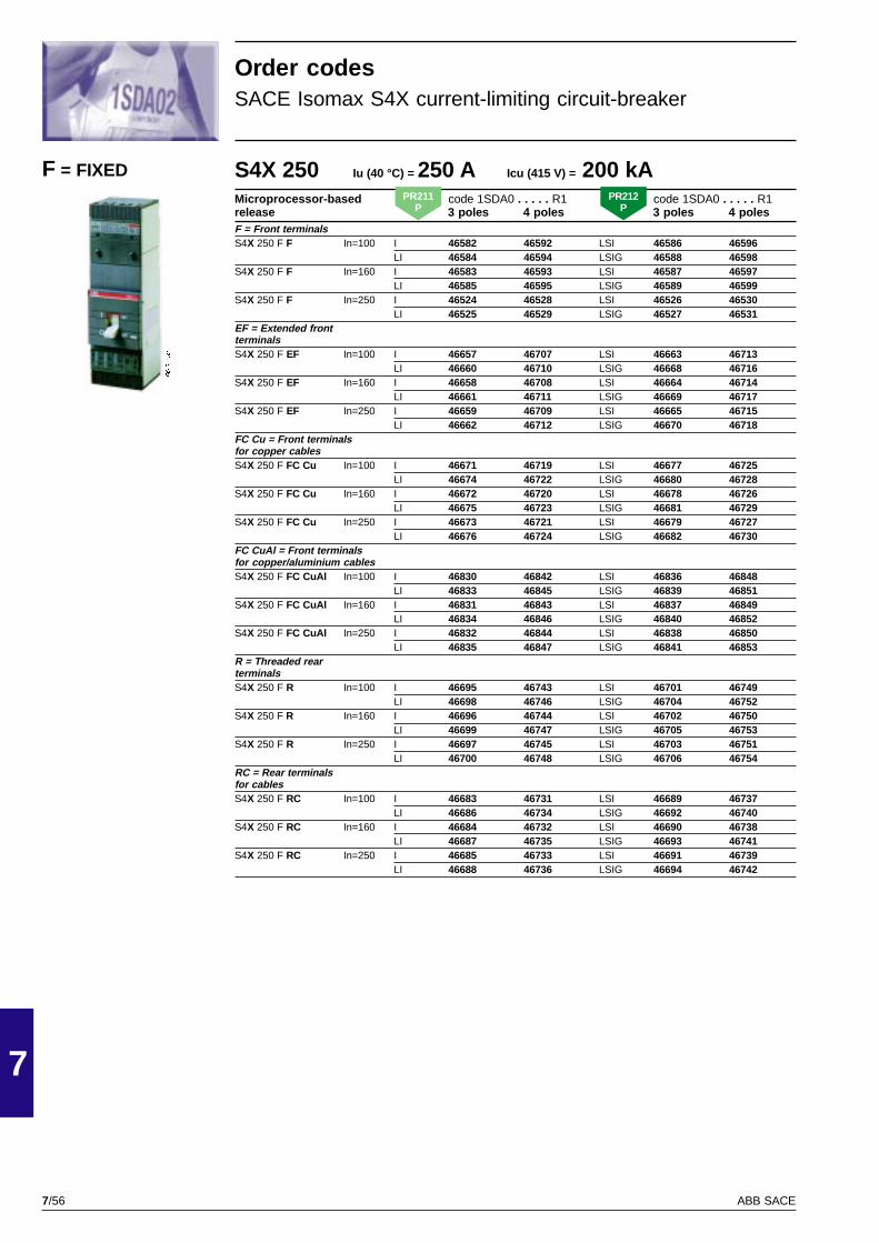
7/56
7
ABB SACE
GSIS9152
S4X 250 Iu (40 °C) = 250 A Icu (415 V) = 200 kAMicroprocessor-based code 1SDA0 . . . . . R1 code 1SDA0 . . . . . R1release 3 poles 4 poles 3 poles 4 polesF = Front terminalsS4X 250 F F In=100 I 46582 46592 LSI 46586 46596
LI 46584 46594 LSIG 46588 46598S4X 250 F F In=160 I 46583 46593 LSI 46587 46597
LI 46585 46595 LSIG 46589 46599S4X 250 F F In=250 I 46524 46528 LSI 46526 46530
LI 46525 46529 LSIG 46527 46531EF = Extended frontterminalsS4X 250 F EF In=100 I 46657 46707 LSI 46663 46713
LI 46660 46710 LSIG 46668 46716S4X 250 F EF In=160 I 46658 46708 LSI 46664 46714
LI 46661 46711 LSIG 46669 46717S4X 250 F EF In=250 I 46659 46709 LSI 46665 46715
LI 46662 46712 LSIG 46670 46718FC Cu = Front terminalsfor copper cablesS4X 250 F FC Cu In=100 I 46671 46719 LSI 46677 46725
LI 46674 46722 LSIG 46680 46728S4X 250 F FC Cu In=160 I 46672 46720 LSI 46678 46726
LI 46675 46723 LSIG 46681 46729S4X 250 F FC Cu In=250 I 46673 46721 LSI 46679 46727
LI 46676 46724 LSIG 46682 46730FC CuAl = Front terminalsfor copper/aluminium cablesS4X 250 F FC CuAl In=100 I 46830 46842 LSI 46836 46848
LI 46833 46845 LSIG 46839 46851S4X 250 F FC CuAl In=160 I 46831 46843 LSI 46837 46849
LI 46834 46846 LSIG 46840 46852S4X 250 F FC CuAl In=250 I 46832 46844 LSI 46838 46850
LI 46835 46847 LSIG 46841 46853R = Threaded rearterminalsS4X 250 F R In=100 I 46695 46743 LSI 46701 46749
LI 46698 46746 LSIG 46704 46752S4X 250 F R In=160 I 46696 46744 LSI 46702 46750
LI 46699 46747 LSIG 46705 46753S4X 250 F R In=250 I 46697 46745 LSI 46703 46751
LI 46700 46748 LSIG 46706 46754RC = Rear terminalsfor cablesS4X 250 F RC In=100 I 46683 46731 LSI 46689 46737
LI 46686 46734 LSIG 46692 46740S4X 250 F RC In=160 I 46684 46732 LSI 46690 46738
LI 46687 46735 LSIG 46693 46741S4X 250 F RC In=250 I 46685 46733 LSI 46691 46739
LI 46688 46736 LSIG 46694 46742
F = FIXED
Order codesSACE Isomax S4X current-limiting circuit-breaker
PR211P
PR212P
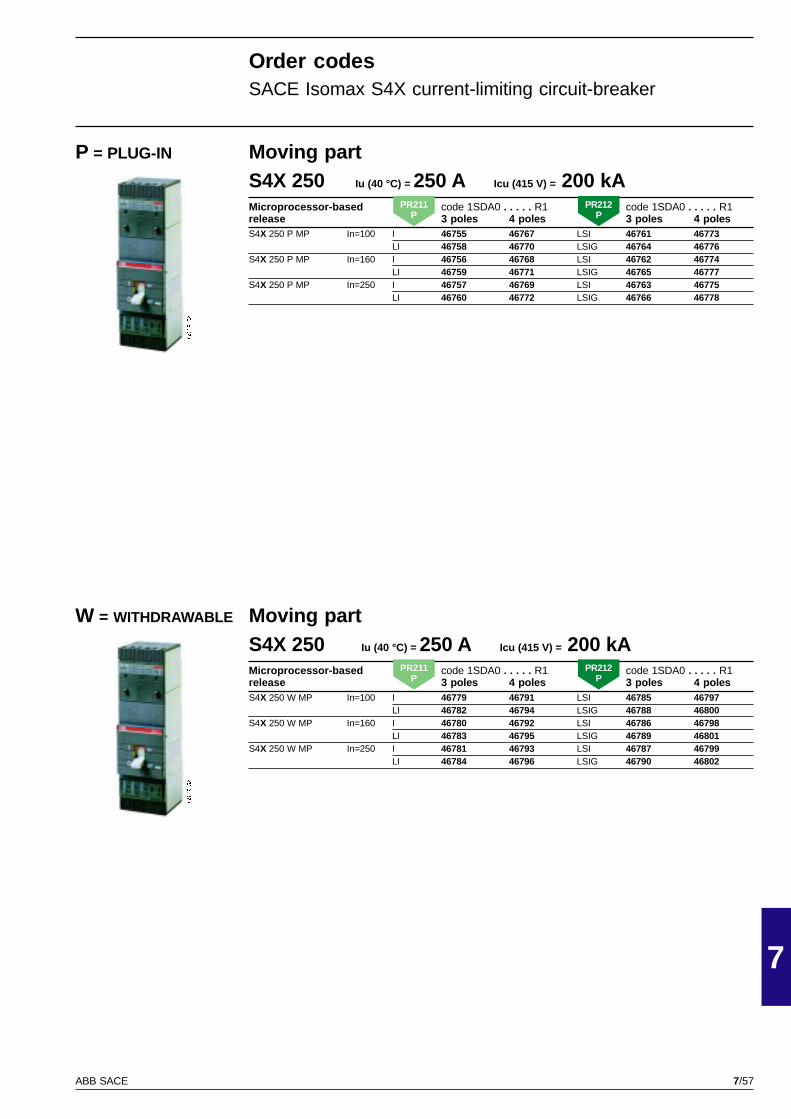
7/57
7
ABB SACE
GSIS9152
GSIS9152
Moving partS4X 250 Iu (40 °C) = 250 A Icu (415 V) = 200 kAMicroprocessor-based code 1SDA0 . . . . . R1 code 1SDA0 . . . . . R1release 3 poles 4 poles 3 poles 4 polesS4X 250 P MP In=100 I 46755 46767 LSI 46761 46773
LI 46758 46770 LSIG 46764 46776S4X 250 P MP In=160 I 46756 46768 LSI 46762 46774
LI 46759 46771 LSIG 46765 46777S4X 250 P MP In=250 I 46757 46769 LSI 46763 46775
LI 46760 46772 LSIG 46766 46778
Moving partS4X 250 Iu (40 °C) = 250 A Icu (415 V) = 200 kAMicroprocessor-based code 1SDA0 . . . . . R1 code 1SDA0 . . . . . R1release 3 poles 4 poles 3 poles 4 polesS4X 250 W MP In=100 I 46779 46791 LSI 46785 46797
LI 46782 46794 LSIG 46788 46800S4X 250 W MP In=160 I 46780 46792 LSI 46786 46798
LI 46783 46795 LSIG 46789 46801S4X 250 W MP In=250 I 46781 46793 LSI 46787 46799
LI 46784 46796 LSIG 46790 46802
P = PLUG-IN
W = WITHDRAWABLE
Order codesSACE Isomax S4X current-limiting circuit-breaker
PR211P
PR212P
PR211P
PR212P

7/58
7
ABB SACE
GSIS9153
S6X 400 Iu (40 °C) = 400 A Icu (415 V) = 200 kAMicroprocessor-based code 1SDA0 . . . . . R1 code 1SDA0 . . . . . R1release 3 poles 4 poles 3 poles 4 polesF = Front terminalsS6X 400 F F In=320 I 47595 47601 LSI 47597 47603
LI 47596 47602 LSIG 47598 47604S6X 400 F F In=400 I 46534 46538 LSI 46536 46540
LI 46535 46539 LSIG 46537 46541EF = Extended frontterminalsS6X 400 F EF In=320 I 47661 47693 LSI 47665 47697
LI 47663 47695 LSIG 47667 47699S6X 400 F EF In=400 I 47660 47692 LSI 47664 47696
LI 47662 47694 LSIG 47666 47698FC CuAl = Front terminalsfor copper/aluminium cablesS6X 400 F FC CuAl In=320 I 47669 47701 LSI 47673 47704
LI 47671 47703 LSIG 47675 47707S6X 400 F FC CuAl In=400 I 47668 47700 LSI 47672 47705
LI 47670 47702 LSIG 47674 47706R = Threaded rearterminalsS6X 400 F R In=320 I 47685 47717 LSI 47689 47721
LI 47687 47719 LSIG 47691 47723S6X 400 F R In=400 I 47684 47716 LSI 47688 47720
LI 47686 47718 LSIG 47690 47722RC = Rear terminalsfor cablesS6X 400 F RC In=320 I 47677 47709 LSI 47681 47713
LI 47679 47711 LSIG 47683 47715S6X 400 F RC In=400 I 47676 47708 LSI 47680 47712
LI 47678 47710 LSIG 47682 47714
S6X 630 Iu (40 °C) = 630 A Icu (415 V) = 200 kAMicroprocessor-based code 1SDA0 . . . . . R1 code 1SDA0 . . . . . R1release 3 poles 4 poles 3 poles 4 polesF = Front terminalsS6X 630 F F In=630 I 46560 46564 LSI 46562 46566
LI 46561 46565 LSIG 46563 46567EF = Extended frontterminalsS6X 630 F EF In=630 I 47724 47744 LSI 47726 47746
LI 47725 47745 LSIG 47727 47747FC CuAl = Front terminalsfor copper/aluminium cablesS6X 630 F FC CuAl In=630 I 47729 47749 LSI 47731 47751
LI 47730 47750 LSIG 47732 47752R = Threaded rearterminalsS6X 630 F R In=630 I 47739 47759 LSI 47741 47761
LI 47740 47760 LSIG 47742 47762RC = Rear terminalsfor cablesS6X 630 F RC In=630 I 47734 47754 LSI 47736 47756
LI 47735 47755 LSIG 47737 47757
F = FIXED
Order codesSACE Isomax S6X current-limiting circuit-breaker
PR211P
PR212P
PR211P
PR212P
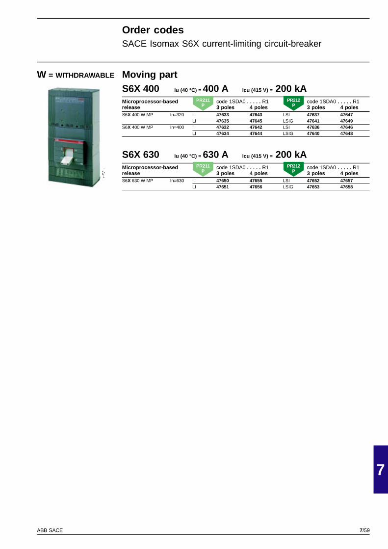
7/59
7
ABB SACE
GSIS9153
Moving partS6X 400 Iu (40 °C) = 400 A Icu (415 V) = 200 kAMicroprocessor-based code 1SDA0 . . . . . R1 code 1SDA0 . . . . . R1release 3 poles 4 poles 3 poles 4 polesS6X 400 W MP In=320 I 47633 47643 LSI 47637 47647
LI 47635 47645 LSIG 47641 47649S6X 400 W MP In=400 I 47632 47642 LSI 47636 47646
LI 47634 47644 LSIG 47640 47648
S6X 630 Iu (40 °C) = 630 A Icu (415 V) = 200 kAMicroprocessor-based code 1SDA0 . . . . . R1 code 1SDA0 . . . . . R1release 3 poles 4 poles 3 poles 4 polesS6X 630 W MP In=630 I 47650 47655 LSI 47652 47657
LI 47651 47656 LSIG 47653 47658
W = WITHDRAWABLE
Order codesSACE Isomax S6X current-limiting circuit-breaker
PR211P
PR212P
PR211P
PR212P

7/60
7
ABB SACE
GSIS9154
GSIS9154
Moving partS2X 80 Iu (40 °C) = 80 A Icu (415 V) = 70 kAMagnetic only code 1SDA0 . . . . . R1release 3 polesS2X 80 P MP R 1 13A 50269S2X 80 P MP R 1.6 21A 50270S2X 80 P MP R 2 26A 50271S2X 80 P MP R 2.5 32A 50272S2X 80 P MP R 3.2 41A 50273S2X 80 P MP R 4 52A 50274S2X 80 P MP R 5 65A 50275S2X 80 P MP R 6.5 84A 50276S2X 80 P MP R 8.5 110A 50277S2X 80 P MP R 11 145A 50278S2X 80 P MP R 12.5 163A 50279S2X 80 P MP R 16 210A 50280S2X 80 P MP R 20 260A 50281S2X 80 P MP R 25 325A 50282S2X 80 P MP R 32 415A 50283S2X 80 P MP R 42 545A 50284S2X 80 P MP R 52 680A 50285S2X 80 P MP R 63 820A 50286S2X 80 P MP R 80 1040A 50287
P = PLUG-IN
S2X 80 Iu (40 °C) = 80 A Icu (415 V) = 70 kAMagnetic only code 1SDA0 . . . . . R1release 3 polesFC Cu = Front terminals for copper cablesS2X 80 F FC Cu R 1 13A 50231S2X 80 F FC Cu R 1.6 21A 50232S2X 80 F FC Cu R 2 26A 50233S2X 80 F FC Cu R 2.5 32A 50234S2X 80 F FC Cu R 3.2 42A 50235S2X 80 F FC Cu R 4 52A 50236S2X 80 F FC Cu R 5 65A 50237S2X 80 F FC Cu R 6.5 84A 50238S2X 80 F FC Cu R 8.5 110A 50239S2X 80 F FC Cu R 11 145A 50240S2X 80 F FC Cu R 12.5 163A 50241S2X 80 F FC Cu R 16 210A 50242S2X 80 F FC Cu R 20 260A 50243S2X 80 F FC Cu R 25 325A 50244S2X 80 F FC Cu R 32 415A 50245S2X 80 F FC Cu R 42 545A 50246S2X 80 F FC Cu R 52 680A 50247S2X 80 F FC Cu R 63 820A 50248S2X 80 F FC Cu R 80 1040A 50249R = Threaded rear terminalsS2X 80 F R R 1 13A 50250S2X 80 F R R 1.6 21A 50251S2X 80 F R R 2 26A 50252S2X 80 F R R 2.5 32A 50253S2X 80 F R R 3.2 42A 50254S2X 80 F R R 4 52A 50255S2X 80 F R R 5 65A 50256S2X 80 F R R 6.5 84A 50257S2X 80 F R R 8.5 110A 50258S2X 80 F R R 11 145A 50259S2X 80 F R R 12.5 163A 50260S2X 80 F R R 16 210A 50261S2X 80 F R R 20 260A 50262S2X 80 F R R 25 325A 50263S2X 80 F R R 32 415A 50264S2X 80 F R R 42 545A 50265S2X 80 F R R 52 680A 50266S2X 80 F R R 63 820A 50267S2X 80 F R R 80 1040A 50268
F = FIXED
Order codesSACE Isomax S2X 80 circuit-breaker for motor protection
Im
Im

7/61
7
ABB SACE
PSIS9607
S3N 160 Iu (40 °C) = 160 A Icu (415 V) = 35 kAMagnetic only code 1SDA0 . . . . . R1release 3 polesF = Front terminalsS3N 160 F F R 3 12 ... 36A 47782S3N 160 F F R 5 20 ... 60A 47783S3N 160 F F R 10 40 ... 120A 47784S3N 160 F F R 25 100 ... 300A 47785S3N 160 F F R 50 200 ... 600A 47786S3N 160 F F R 100 400 ... 1200A 47787S3N 160 F F R 125 500 ... 1500A 47788S3N 160 F F R 160 640 ... 1600A 47789
S3H 160 Iu (40 °C) = 160 A Icu (415 V) = 65 kAMagnetic only code 1SDA0 . . . . . R1release 3 polesF = Front terminalsS3H 160 F F R 50 200 ... 600A 45185S3H 160 F F R 100 400 ... 1200A 45186S3H 160 F F R 125 500 ... 1500A 45187S3H 160 F F R 160 640 ... 1600A 45188
S3L 160 Iu (40 °C) = 160 A Icu (415 V) = 85 kAMagnetic only code 1SDA0 . . . . . R1release 3 polesF = Front terminalsS3L 160 F F R 50 200 ... 600A 50544S3L 160 F F R 100 400 ... 1200A 50545S3L 160 F F R 125 500 ... 1500A 50546S3L 160 F F R 160 640 ... 1600A 50547
S3N 250 Iu (40 °C) = 250 A Icu (415 V) = 35 kAMagnetic only code 1SDA0 . . . . . R1release 3 polesF = Front terminalsS3N 250 F F R 160 640 ... 1920A 48651S3N 250 F F R 200 800 ... 2400A 48654
S3H 250 Iu (40 °C) = 250 A Icu (415 V) = 65 kAMagnetic only code 1SDA0 . . . . . R1release 3 polesF = Front terminalsS3H 250 F F R 160 640 ... 1920A 48657S3H 250 F F R 200 800 ... 2400A 48658
S3L 250 Iu (40 °C) = 250 A Icu (415 V) = 85 kAMagnetic only code 1SDA0 . . . . . R1release 3 polesF = Front terminalsS3L 250 F F R 160 640 ... 1920A 50548S3L 250 F F R 200 800 ... 2400A 50549
F = FIXED
Order codesSACE Isomax S3 circuit-breaker for motor protection
NotePlug-in and withdrawable version are taken from the corresponding fixed version by means of the conversionkits indicated on page 80.
Im
Im
Im
Im
Im
Im
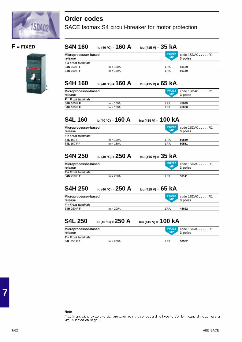
7/62
7
ABB SACE
PSIS9610
S4N 160 Iu (40 °C) = 160 A Icu (415 V) = 35 kAMicroprocessor-based code 1SDA0 . . . . . R1release 3 polesF = Front terminalsS4N 160 F F In = 100A LRIU 50139S4N 160 F F In = 160A LRIU 50140
S4H 160 Iu (40 °C) = 160 A Icu (415 V) = 65 kAMicroprocessor-based code 1SDA0 . . . . . R1release 3 polesF = Front terminalsS4H 160 F F In = 100A LRIU 45049S4H 160 F F In = 160A LRIU 45050
S4L 160 Iu (40 °C) = 160 A Icu (415 V) = 100 kAMicroprocessor-based code 1SDA0 . . . . . R1release 3 polesF = Front terminalsS4L 160 F F In = 100A LRIU 50550S4L 160 F F In = 160A LRIU 50551
S4N 250 Iu (40 °C) = 250 A Icu (415 V) = 35 kAMicroprocessor-based code 1SDA0 . . . . . R1release 3 polesF = Front terminalsS4N 250 F F In = 200A LRIU 50141
S4H 250 Iu (40 °C) = 250 A Icu (415 V) = 65 kAMicroprocessor-based code 1SDA0 . . . . . R1release 3 polesF = Front terminalsS4H 250 F F In = 200A LRIU 48662
S4L 250 Iu (40 °C) = 250 A Icu (415 V) = 100 kAMicroprocessor-based code 1SDA0 . . . . . R1release 3 polesF = Front terminalsS4L 250 F F In = 200A LRIU 50552
F = FIXED
Order codesSACE Isomax S4 circuit-breaker for motor protection
NotePlug-in and withdrawable version are taken from the corresponding fixed version by means of the conversionkits indicated on page 80.
PR212MP
PR212MP
PR212MP
PR212MP
PR212MP
PR212MP

7/63
7
ABB SACE
PSIS9613
PSIS9616
PSIS9620
S5N 400 Iu (40 °C) = 400 A Icu (415 V) = 35 kAMicroprocessor-based code 1SDA0 . . . . . R1release 3 polesF = Front terminalsS5N 400 F F In = 320A LRIU 50142
S5H 400 Iu (40 °C) = 400 A Icu (415 V) = 65 kAMicroprocessor-based code 1SDA0 . . . . . R1release 3 polesF = Front terminalsS5H 400 F F In = 320A LRIU 45051
S5L 400 Iu (40 °C) = 400 A Icu (415 V) = 100 kAMicroprocessor-based code 1SDA0 . . . . . R1release 3 polesF = Front terminalsS5L 400 F F In = 320A LRIU 50553
S6N 800 Iu (40 °C) = 800 A Icu (415 V) = 35 kAMicroprocessor-based code 1SDA0 . . . . . R1release 3 polesF = Front terminalsS6N 800 F F In = 630A LRIU 50143
S6H 800 Iu (40 °C) = 800 A Icu (415 V) = 65 kAMicroprocessor-based code 1SDA0 . . . . . R1release 3 polesF = Front terminalsS6H 800 F F In = 630A LRIU 45052
S6L 800 Iu (40 °C) = 800 A Icu (415 V) = 100 kAMicroprocessor-based code 1SDA0 . . . . . R1release 3 polesF = Front terminalsS6L 800 F F In = 630A LRIU 50554
S7S 1250 Iu (40 °C) = 1250 A Icu (415 V) = 50 kAMicroprocessor-based code 1SDA0 . . . . . R1release 3 polesF = Front terminalsS7S 1250 F F In = 1000A LRIU 50144
S7H 1250 Iu (40 °C) = 1250 A Icu (415 V) = 65 kAMicroprocessor-based code 1SDA0 . . . . . R1release 3 polesF = Front terminalsS7H 1250 F F In = 1000A LRIU 45053
F = FIXED
Order codesSACE Isomax S5-S6-S7 circuit-breakers for motor protection
NoteWithdrawable version are taken from the corresponding fixed version by means of the conversion kitsindicated on page 80.
PR212MP
PR212MP
PR212MP
PR212MP
PR212MP
PR212MP
PR212MP
PR212MP
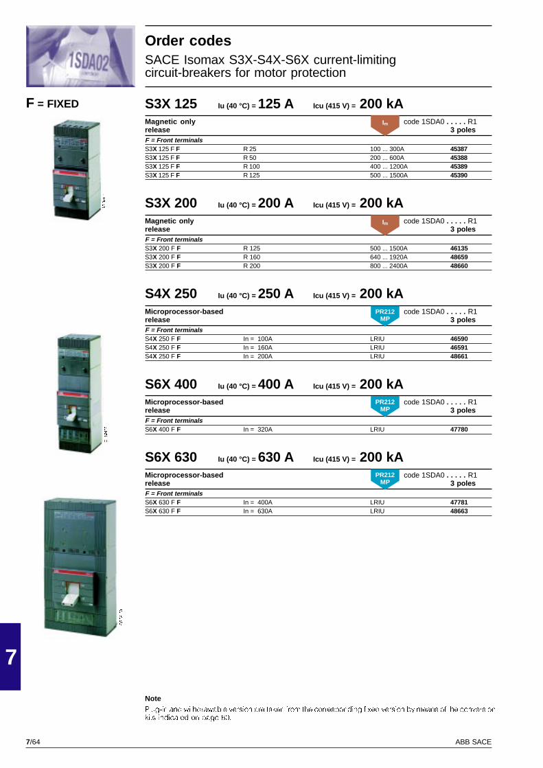
7/64
7
ABB SACE
GSIS9153
GSIS9152
GSIS9151
S3X 125 Iu (40 °C) = 125 A Icu (415 V) = 200 kAMagnetic only code 1SDA0 . . . . . R1release 3 polesF = Front terminalsS3X 125 F F R 25 100 ... 300A 45387S3X 125 F F R 50 200 ... 600A 45388S3X 125 F F R 100 400 ... 1200A 45389S3X 125 F F R 125 500 ... 1500A 45390
S3X 200 Iu (40 °C) = 200 A Icu (415 V) = 200 kAMagnetic only code 1SDA0 . . . . . R1release 3 polesF = Front terminalsS3X 200 F F R 125 500 ... 1500A 46135S3X 200 F F R 160 640 ... 1920A 48659S3X 200 F F R 200 800 ... 2400A 48660
S4X 250 Iu (40 °C) = 250 A Icu (415 V) = 200 kAMicroprocessor-based code 1SDA0 . . . . . R1release 3 polesF = Front terminalsS4X 250 F F In = 100A LRIU 46590S4X 250 F F In = 160A LRIU 46591S4X 250 F F In = 200A LRIU 48661
S6X 400 Iu (40 °C) = 400 A Icu (415 V) = 200 kAMicroprocessor-based code 1SDA0 . . . . . R1release 3 polesF = Front terminalsS6X 400 F F In = 320A LRIU 47780
S6X 630 Iu (40 °C) = 630 A Icu (415 V) = 200 kAMicroprocessor-based code 1SDA0 . . . . . R1release 3 polesF = Front terminalsS6X 630 F F In = 400A LRIU 47781S6X 630 F F In = 630A LRIU 48663
F = FIXED
Order codesSACE Isomax S3X-S4X-S6X current-limitingcircuit-breakers for motor protection
NotePlug-in and withdrawable version are taken from the corresponding fixed version by means of the conversionkits indicated on page 80.
PR212MP
PR212MP
PR212MP
Im
Im
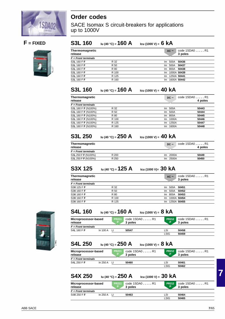
7/65
7
ABB SACE
PSIS9607
PSIS9610
S3L 160 Iu (40 °C) = 160 A Icu (1000 V) = 6 kAThermomagnetic code 1SDA0 . . . . . R1release 3 polesF = Front terminalsS3L 160 F F R 32 Im 500A 50436S3L 160 F F R 50 Im 500A 50437S3L 160 F F R 80 Im 800A 50438S3L 160 F F R 100 Im 1000A 50439S3L 160 F F R 125 Im 1250A 50441S3L 160 F F R 160 Im 1600A 50442
S3L 160 Iu (40 °C) = 160 A Icu (1000 V) = 40 kAThermomagnetic code 1SDA0 . . . . . R1release 4 polesF = Front terminalsS3L 160 F F (N100%) R 32 Im 500A 50443S3L 160 F F (N100%) R 50 Im 500A 50444S3L 160 F F (N100%) R 80 Im 800A 50445S3L 160 F F (N100%) R 100 Im 1000A 50446S3L 160 F F (N100%) R 125 Im 1250A 50447S3L 160 F F (N100%) R 160 Im 1600A 50448
S3L 250 Iu (40 °C) = 250 A Icu (1000 V) = 40 kAThermomagnetic code 1SDA0 . . . . . R1release 4 polesF = Front terminalsS3L 250 F F (N100%) R 200 Im 2000A 50449S3L 250 F F (N100%) R 250 Im 2500A 50450
S3X 125 Iu (40 °C) = 125 A Icu (1000 V)= 30 kAThermomagnetic code 1SDA0 . . . . . R1release 3 polesF = Front terminalsS3X 125 F F R 32 Im 500A 50451S3X 160 F F R 50 Im 500A 50452S3X 160 F F R 80 Im 800A 50453S3X 160 F F R 100 Im 1000A 50454S3X 160 F F R 125 Im 1250A 50455
S4L 160 Iu (40 °C) = 160 A Icu (1000 V) = 8 kAMicroprocessor-based code 1SDA0 . . . . . R1 code 1SDA0 . . . . . R1release 3 poles 3 polesF = Front terminalsS4L 160 F F In 100 A LI 50547 LSI 50458
LSIG 50459
S4L 250 Iu (40 °C) = 250 A Icu (1000 V) = 8 kAMicroprocessor-based code 1SDA0 . . . . . R1 code 1SDA0 . . . . . R1release 3 poles 3 polesF = Front terminalsS4L 250 F F In 250 A LI 50460 LSI 50461
LSIG 50462
S4X 250 Iu (40 °C) = 250 A Icu (1000 V) = 30 kAMicroprocessor-based code 1SDA0 . . . . . R1 code 1SDA0 . . . . . R1release 3 poles 3 polesF = Front terminalsS4X 250 F F In 250 A LI 50463 LSI 50464
LSIG 50465
Order codesSACE Isomax S circuit-breakers for applicationsup to 1000V
F = FIXED
AC ~
DC –
DC –
AC ~
PR211P
PR212P
PR211P
PR212P
PR211P
PR212P
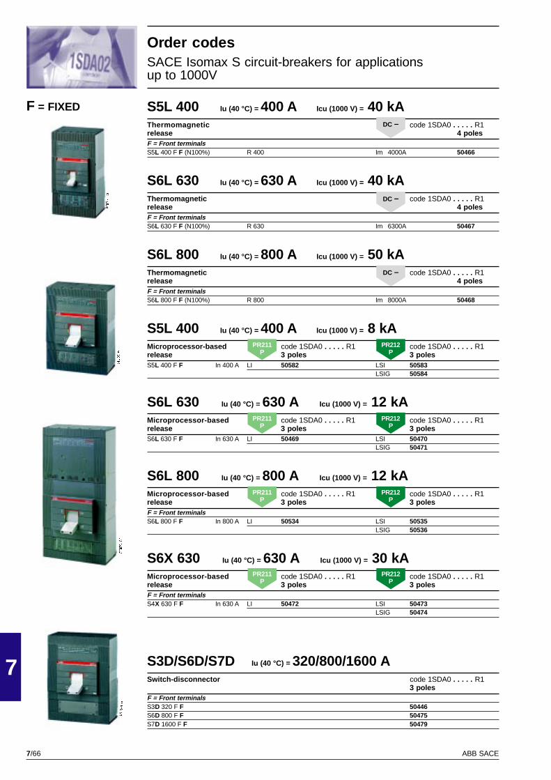
7/66
7
ABB SACE
PSIS9616
PSIS9613
PSIS9155
GSIS9153
S5L 400 Iu (40 °C) = 400 A Icu (1000 V) = 40 kAThermomagnetic code 1SDA0 . . . . . R1release 4 polesF = Front terminalsS5L 400 F F (N100%) R 400 Im 4000A 50466
S6L 630 Iu (40 °C) = 630 A Icu (1000 V) = 40 kAThermomagnetic code 1SDA0 . . . . . R1release 4 polesF = Front terminalsS6L 630 F F (N100%) R 630 Im 6300A 50467
S6L 800 Iu (40 °C) = 800 A Icu (1000 V) = 50 kAThermomagnetic code 1SDA0 . . . . . R1release 4 polesF = Front terminalsS6L 800 F F (N100%) R 800 Im 8000A 50468
S5L 400 Iu (40 °C) = 400 A Icu (1000 V) = 8 kAMicroprocessor-based code 1SDA0 . . . . . R1 code 1SDA0 . . . . . R1release 3 poles 3 polesS5L 400 F F In 400 A LI 50582 LSI 50583
LSIG 50584
S6L 630 Iu (40 °C) = 630 A Icu (1000 V) = 12 kAMicroprocessor-based code 1SDA0 . . . . . R1 code 1SDA0 . . . . . R1release 3 poles 3 polesS6L 630 F F In 630 A LI 50469 LSI 50470
LSIG 50471
S6L 800 Iu (40 °C) = 800 A Icu (1000 V) = 12 kAMicroprocessor-based code 1SDA0 . . . . . R1 code 1SDA0 . . . . . R1release 3 poles 3 polesF = Front terminalsS6L 800 F F In 800 A LI 50534 LSI 50535
LSIG 50536
S6X 630 Iu (40 °C) = 630 A Icu (1000 V) = 30 kAMicroprocessor-based code 1SDA0 . . . . . R1 code 1SDA0 . . . . . R1release 3 poles 3 polesF = Front terminalsS4X 630 F F In 630 A LI 50472 LSI 50473
LSIG 50474
S3D/S6D/S7D Iu (40 °C) = 320/800/1600 ASwitch-disconnector code 1SDA0 . . . . . R1
3 polesF = Front terminalsS3D 320 F F 50446S6D 800 F F 50475S7D 1600 F F 50479
F = FIXED
Order codesSACE Isomax S circuit-breakers for applicationsup to 1000V
DC –
DC –
DC –
PR211P
PR212P
PR211P
PR212P
PR211P
PR212P
PR211P
PR212P

7/67
7
ABB SACE
PSIS9604
PSIS9604
S2D 125 Iu (40 °C) = 125 A Icw (1s) = 2.2 kA Icm (415 V) = 3.1 kASwitch-disconnector code 1SDA0 . . . . . R1
3 poles 4 polesFC Cu = Front terminalsfor copper cablesS2D 125 F FC Cu 45057 45063FC CuAl = Front terminalsfor copper/aluminium cablesS2D 125 F FC CuAl* 45058 45064S2D 125 F FC CuAl** 45059 45065EF = Extended front terminalsS2D 125 F EF 45056 45062R = Threaded rear terminalsS2D 125 F R 45060 45066
S2D 160 Iu (40 °C) = 160 A Icw (1s) = 2.2 kA Icm (415 V) = 3.1 kASwitch-disconnector code 1SDA0 . . . . . R1
3 poles 4 polesFC Cu = Front terminalsfor copper cablesS2D 160 F FC Cu 20632 45071FC CuAl = Front terminalsfor copper/aluminium cablesS2D 160 F FC CuAl* 45068 45072S2D 160 F FC CuAl** 20633 45074EF = Extended front terminalsS2D 160 F EF 20630 45070R = Threaded rear terminalsS2D 160 F R 20634 45073
Moving partS2D 125 Iu (40 °C) = 125 A Icw (1s) = 2.2 kA Icm (415 V) = 3.1 kASwitch-disconnector code 1SDA0 . . . . . R1
3 poles 4 polesS2D 125 P MP 45061 45067
S2D 160 Iu (40 °C) = 160 A Icw (1s) = 2.2 kA Icm (415 V) = 3.1 kASwitch-disconnector code 1SDA0 . . . . . R1
3 poles 4 polesS2D 160 P MP 45069 45075
* Cable section = 1 x 2.5...50 mm2
** Cable section = 1 x 35...95 mm2
P = PLUG-IN
F = FIXED
Order codesSACE Isomax S2D switch-disconnectors
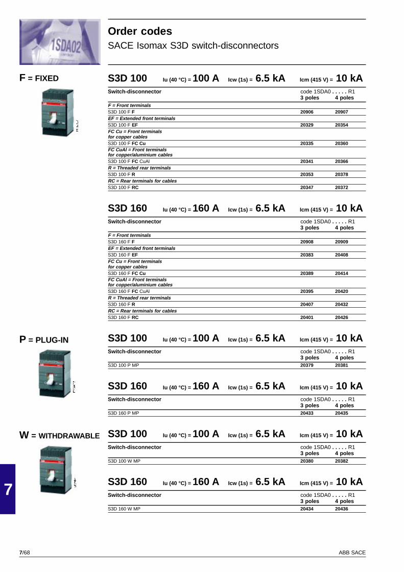
7/68
7
ABB SACE
PSIS9607
PSIS9607
PSIS9607
S3D 100 Iu (40 °C) = 100 A Icw (1s) = 6.5 kA Icm (415 V) = 10 kASwitch-disconnector code 1SDA0 . . . . . R1
3 poles 4 polesF = Front terminalsS3D 100 F F 20906 20907EF = Extended front terminalsS3D 100 F EF 20329 20354FC Cu = Front terminalsfor copper cablesS3D 100 F FC Cu 20335 20360FC CuAl = Front terminalsfor copper/aluminium cablesS3D 100 F FC CuAl 20341 20366R = Threaded rear terminalsS3D 100 F R 20353 20378RC = Rear terminals for cablesS3D 100 F RC 20347 20372
S3D 160 Iu (40 °C) = 160 A Icw (1s) = 6.5 kA Icm (415 V) = 10 kASwitch-disconnector code 1SDA0 . . . . . R1
3 poles 4 polesF = Front terminalsS3D 160 F F 20908 20909EF = Extended front terminalsS3D 160 F EF 20383 20408FC Cu = Front terminalsfor copper cablesS3D 160 F FC Cu 20389 20414FC CuAl = Front terminalsfor copper/aluminium cablesS3D 160 F FC CuAl 20395 20420R = Threaded rear terminalsS3D 160 F R 20407 20432RC = Rear terminals for cablesS3D 160 F RC 20401 20426
S3D 100 Iu (40 °C) = 100 A Icw (1s) = 6.5 kA Icm (415 V) = 10 kASwitch-disconnector code 1SDA0 . . . . . R1
3 poles 4 polesS3D 100 P MP 20379 20381
S3D 160 Iu (40 °C) = 160 A Icw (1s) = 6.5 kA Icm (415 V) = 10 kASwitch-disconnector code 1SDA0 . . . . . R1
3 poles 4 polesS3D 160 P MP 20433 20435
S3D 100 Iu (40 °C) = 100 A Icw (1s) = 6.5 kA Icm (415 V) = 10 kASwitch-disconnector code 1SDA0 . . . . . R1
3 poles 4 polesS3D 100 W MP 20380 20382
S3D 160 Iu (40 °C) = 160 A Icw (1s) = 6.5 kA Icm (415 V) = 10 kASwitch-disconnector code 1SDA0 . . . . . R1
3 poles 4 polesS3D 160 W MP 20434 20436
F = FIXED
W = WITHDRAWABLE
P = PLUG-IN
Order codesSACE Isomax S3D switch-disconnectors
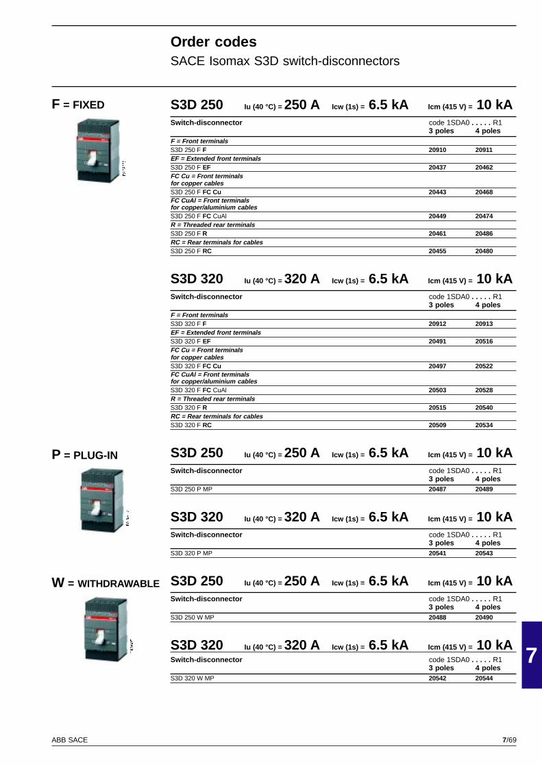
7/69
7
ABB SACE
PSIS9607
PSIS9607
PSIS9607
S3D 250 Iu (40 °C) = 250 A Icw (1s) = 6.5 kA Icm (415 V) = 10 kASwitch-disconnector code 1SDA0 . . . . . R1
3 poles 4 polesF = Front terminalsS3D 250 F F 20910 20911EF = Extended front terminalsS3D 250 F EF 20437 20462FC Cu = Front terminalsfor copper cablesS3D 250 F FC Cu 20443 20468FC CuAl = Front terminalsfor copper/aluminium cablesS3D 250 F FC CuAl 20449 20474R = Threaded rear terminalsS3D 250 F R 20461 20486RC = Rear terminals for cablesS3D 250 F RC 20455 20480
S3D 320 Iu (40 °C) = 320 A Icw (1s) = 6.5 kA Icm (415 V) = 10 kASwitch-disconnector code 1SDA0 . . . . . R1
3 poles 4 polesF = Front terminalsS3D 320 F F 20912 20913EF = Extended front terminalsS3D 320 F EF 20491 20516FC Cu = Front terminalsfor copper cablesS3D 320 F FC Cu 20497 20522FC CuAl = Front terminalsfor copper/aluminium cablesS3D 320 F FC CuAl 20503 20528R = Threaded rear terminalsS3D 320 F R 20515 20540RC = Rear terminals for cablesS3D 320 F RC 20509 20534
S3D 250 Iu (40 °C) = 250 A Icw (1s) = 6.5 kA Icm (415 V) = 10 kASwitch-disconnector code 1SDA0 . . . . . R1
3 poles 4 polesS3D 250 P MP 20487 20489
S3D 320 Iu (40 °C) = 320 A Icw (1s) = 6.5 kA Icm (415 V) = 10 kASwitch-disconnector code 1SDA0 . . . . . R1
3 poles 4 polesS3D 320 P MP 20541 20543
S3D 250 Iu (40 °C) = 250 A Icw (1s) = 6.5 kA Icm (415 V) = 10 kASwitch-disconnector code 1SDA0 . . . . . R1
3 poles 4 polesS3D 250 W MP 20488 20490
S3D 320 Iu (40 °C) = 320 A Icw (1s) = 6.5 kA Icm (415 V) = 10 kASwitch-disconnector code 1SDA0 . . . . . R1
3 poles 4 polesS3D 320 W MP 20542 20544
Order codesSACE Isomax S3D switch-disconnectors
F = FIXED
W = WITHDRAWABLE
P = PLUG-IN
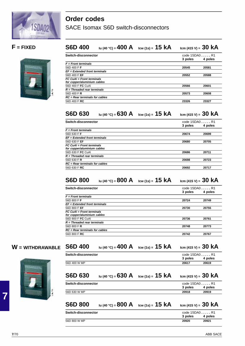
7/70
7
ABB SACE
GSIS9156
GSIS9156
S6D 400 Iu (40 °C) = 400 A Icw (1s) = 15 kA Icm (415 V) = 30 kASwitch-disconnector code 1SDA0 . . . . . R1
3 poles 4 polesF = Front terminalsS6D 400 F F 20545 20581EF = Extended front terminalsS6D 400 F EF 20552 20588FC CuAl = Front terminalsfor copper/aluminium cablesS6D 400 F FC CuAl 20566 20601R = Threaded rear terminalsS6D 400 F R 20573 20608RC = Rear terminals for cablesS6D 400 F RC 23326 23327
S6D 630 Iu (40 °C) = 630 A Icw (1s) = 15 kA Icm (415 V) = 30 kASwitch-disconnector code 1SDA0 . . . . . R1
3 poles 4 polesF = Front terminalsS6D 630 F F 20674 20699EF = Extended front terminalsS6D 630 F EF 20680 20705FC CuAl = Front terminalsfor copper/aluminium cablesS6D 630 F FC CuAl 20686 20711R = Threaded rear terminalsS6D 630 F R 20698 20723RC = Rear terminals for cablesS6D 630 F RC 20692 20717
S6D 800 Iu (40 °C) = 800 A Icw (1s) = 15 kA Icm (415 V) = 30 kASwitch-disconnector code 1SDA0 . . . . . R1
3 poles 4 polesF = Front terminalsS6D 800 F F 20724 20749EF = Extended front terminalsS6D 800 F EF 20730 20755FC CuAl = Front terminalsfor copper/aluminium cablesS6D 800 F FC CuAl 20736 20761R = Threaded rear terminalsS6D 800 F R 20748 20773RC = Rear terminals for cablesS6D 800 F RC 20742 20767
S6D 400 Iu (40 °C) = 400 A Icw (1s) = 15 kA Icm (415 V) = 30 kASwitch-disconnector code 1SDA0 . . . . . R1
3 poles 4 polesS6D 400 W MP 20617 20619
S6D 630 Iu (40 °C) = 630 A Icw (1s) = 15 kA Icm (415 V) = 30 kASwitch-disconnector code 1SDA0 . . . . . R1
3 poles 4 polesS6D 630 W MP 20918 20919
S6D 800 Iu (40 °C) = 800 A Icw (1s) = 15 kA Icm (415 V) = 30 kASwitch-disconnector code 1SDA0 . . . . . R1
3 poles 4 polesS6D 800 W MP 20920 20921
Order codesSACE Isomax S6D switch-disconnectors
F = FIXED
W = WITHDRAWABLE
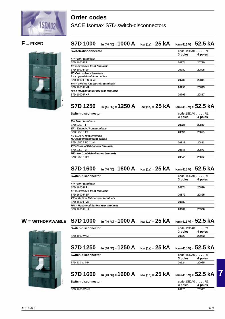
7/71
7
ABB SACE
PSIS9625
PSIS9625
S7D 1000 Iu (40 °C) = 1000 A Icw (1s) = 25 kA Icm (415 V) = 52.5 kASwitch-disconnector code 1SDA0 . . . . . R1
3 poles 4 polesF = Front terminalsS7D 1000 F F 20774 20799EF = Extended front terminalsS7D 1000 F EF 20780 20805FC CuAl = Front terminalsfor copper/aluminium cablesS7D 1000 F FC CuAl 20786 20811VR = Vertical flat-bar rear terminalsS7D 1000 F VR 20798 20823HR = Horizontal flat-bar rear terminalsS7D 1000 F HR 20792 20817
S7D 1250 Iu (40 °C) = 1250 A Icw (1s) = 25 kA Icm (415 V) = 52.5 kASwitch-disconnector code 1SDA0 . . . . . R1
3 poles 4 polesF = Front terminalsS7D 1250 F F 20824 20849EF = Extended front terminalsS7D 1250 F EF 20830 20855FC CuAl = Front terminalsfor copper/aluminium cablesS7D 1250 F FC CuAl 20836 20861VR = Vertical flat-bar rear terminalsS7D 1250 F VR 20848 20873HR = Horizontal flat-bar rear terminalsS7D 1250 F HR 20842 20867
S7D 1600 Iu (40 °C) = 1600 A Icw (1s) = 25 kA Icm (415 V) = 52.5 kASwitch-disconnector code 1SDA0 . . . . . R1
3 poles 4 polesF = Front terminalsS7D 1600 F F 20874 20890EF = Extended front terminalsS7D 1600 F EF 20879 20895VR = Vertical flat-bar rear terminalsS7D 1600 F VR 20889HR = Horizontal flat-bar rear terminalsS7D 1600 F HR 20884 20900
S7D 1000 Iu (40 °C) = 1000 A Icw (1s) = 25 kA Icm (415 V) = 52.5 kASwitch-disconnector code 1SDA0 . . . . . R1
3 poles 4 polesS7D 1000 W MP 20922 20923
S7D 1250 Iu (40 °C) = 1250 A Icw (1s) = 25 kA Icm (415 V) = 52.5 kASwitch-disconnector code 1SDA0 . . . . . R1
3 poles 4 polesS7D 630 W MP 20924 20925
S7D 1600 Iu (40 °C) = 1600 A Icw (1s) = 25 kA Icm (415 V) = 52.5 kASwitch-disconnector code 1SDA0 . . . . . R1
3 poles 4 polesS7D 1600 W MP 20926 20927
Order codesSACE Isomax S7D switch-disconnectors
F = FIXED
W = WITHDRAWABLE
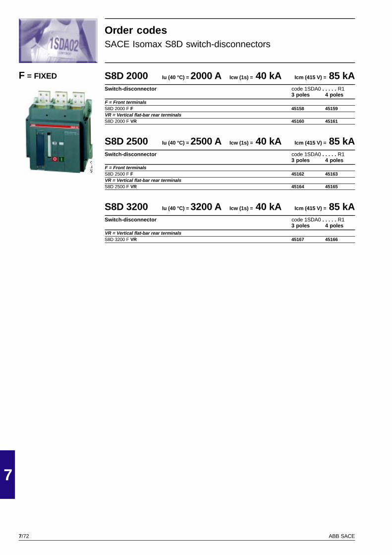
7/72
7
ABB SACE
GSIS9149
S8D 2000 Iu (40 °C) = 2000 A Icw (1s) = 40 kA Icm (415 V) = 85 kASwitch-disconnector code 1SDA0 . . . . . R1
3 poles 4 polesF = Front terminalsS8D 2000 F F 45158 45159VR = Vertical flat-bar rear terminalsS8D 2000 F VR 45160 45161
S8D 2500 Iu (40 °C) = 2500 A Icw (1s) = 40 kA Icm (415 V) = 85 kASwitch-disconnector code 1SDA0 . . . . . R1
3 poles 4 polesF = Front terminalsS8D 2500 F F 45162 45163VR = Vertical flat-bar rear terminalsS8D 2500 F VR 45164 45165
S8D 3200 Iu (40 °C) = 3200 A Icw (1s) = 40 kA Icm (415 V) = 85 kASwitch-disconnector code 1SDA0 . . . . . R1
3 poles 4 polesVR = Vertical flat-bar rear terminalsS8D 3200 F VR 45167 45166
F = FIXED
Order codesSACE Isomax S8D switch-disconnectors
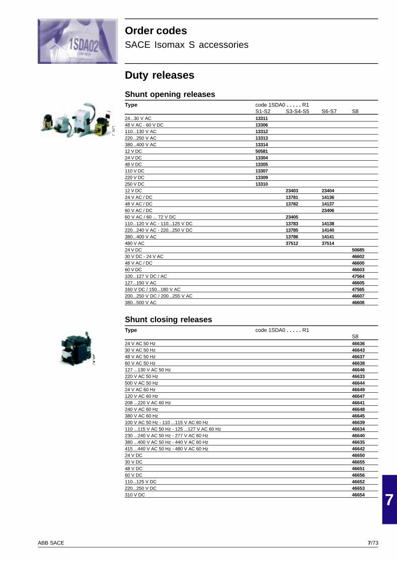
7/73
7
ABB SACE
GSIS9003
GSIS9001
Order codesSACE Isomax S accessories
Duty releases
Shunt opening releasesType code 1SDA0 . . . . . R1
S1-S2 S3-S4-S5 S6-S7 S824...30 V AC 1331148 V AC - 60 V DC 13306110...130 V AC 13312220...250 V AC 13313380...400 V AC 1331412 V DC 5058124 V DC 1330448 V DC 13305110 V DC 13307220 V DC 13309250 V DC 1331012 V DC 23403 2340424 V AC / DC 13781 1413648 V AC / DC 13782 1413760 V AC / DC 2340660 V AC / 60 ... 72 V DC 23405110...120 V AC - 110...125 V DC 13783 14138220...240 V AC - 220...250 V DC 13785 14140380...400 V AC 13786 14141480 V AC 37512 3751424 V DC 5068530 V DC - 24 V AC 4660248 V AC / DC 4660060 V DC 46603100...127 V DC / AC 47564127...150 V AC 46605160 V DC / 150...180 V AC 47565200...250 V DC / 200...255 V AC 46607380...500 V AC 46608
Shunt closing releasesType code 1SDA0 . . . . . R1
S824 V AC 50 Hz 4663630 V AC 50 Hz 4664348 V AC 50 Hz 4663760 V AC 50 Hz 46638127 ...130 V AC 50 Hz 46646220 V AC 50 Hz 46633500 V AC 50 Hz 4664424 V AC 60 Hz 46649120 V AC 60 Hz 46647208 ...220 V AC 60 Hz 46641240 V AC 60 Hz 46648380 V AC 60 Hz 46645100 V AC 50 Hz - 110 ...115 V AC 60 Hz 46639110 ...115 V AC 50 Hz - 125 ...127 V AC 60 Hz 46634230 ...240 V AC 50 Hz - 277 V AC 60 Hz 46640380 ...400 V AC 50 Hz - 440 V AC 60 Hz 46635415 ...440 V AC 50 Hz - 480 V AC 60 Hz 4664224 V DC 4665030 V DC 4665548 V DC 4665160 V DC 46656110...125 V DC 46652220...250 V DC 46653310 V DC 46654
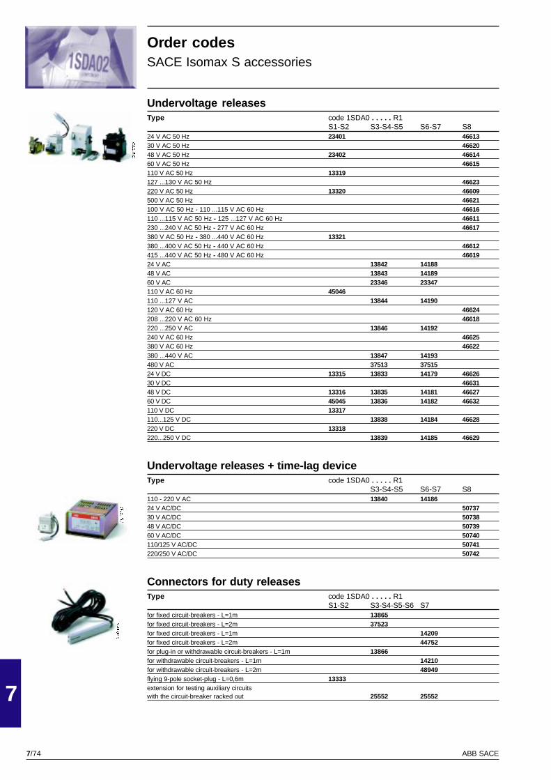
7/74
7
ABB SACE
GSIS9042
GSIS9002
GSIS9013
Order codesSACE Isomax S accessories
Undervoltage releasesType code 1SDA0 . . . . . R1
S1-S2 S3-S4-S5 S6-S7 S824 V AC 50 Hz 23401 4661330 V AC 50 Hz 4662048 V AC 50 Hz 23402 4661460 V AC 50 Hz 46615110 V AC 50 Hz 13319127 ...130 V AC 50 Hz 46623220 V AC 50 Hz 13320 46609500 V AC 50 Hz 46621100 V AC 50 Hz - 110 ...115 V AC 60 Hz 46616110 ...115 V AC 50 Hz - 125 ...127 V AC 60 Hz 46611230 ...240 V AC 50 Hz - 277 V AC 60 Hz 46617380 V AC 50 Hz - 380 ...440 V AC 60 Hz 13321380 ...400 V AC 50 Hz - 440 V AC 60 Hz 46612415 ...440 V AC 50 Hz - 480 V AC 60 Hz 4661924 V AC 13842 1418848 V AC 13843 1418960 V AC 23346 23347110 V AC 60 Hz 45046110 ...127 V AC 13844 14190120 V AC 60 Hz 46624208 ...220 V AC 60 Hz 46618220 ...250 V AC 13846 14192240 V AC 60 Hz 46625380 V AC 60 Hz 46622380 ...440 V AC 13847 14193480 V AC 37513 3751524 V DC 13315 13833 14179 4662630 V DC 4663148 V DC 13316 13835 14181 4662760 V DC 45045 13836 14182 46632110 V DC 13317110...125 V DC 13838 14184 46628220 V DC 13318220...250 V DC 13839 14185 46629
Undervoltage releases + time-lag deviceType code 1SDA0 . . . . . R1
S3-S4-S5 S6-S7 S8110 - 220 V AC 13840 1418624 V AC/DC 5073730 V AC/DC 5073848 V AC/DC 5073960 V AC/DC 50740110/125 V AC/DC 50741220/250 V AC/DC 50742
Connectors for duty releasesType code 1SDA0 . . . . . R1
S1-S2 S3-S4-S5-S6 S7for fixed circuit-breakers - L=1m 13865for fixed circuit-breakers - L=2m 37523for fixed circuit-breakers - L=1m 14209for fixed circuit-breakers - L=2m 44752for plug-in or withdrawable circuit-breakers - L=1m 13866for withdrawable circuit-breakers - L=1m 14210for withdrawable circuit-breakers - L=2m 48949flying 9-pole socket-plug - L=0,6m 13333extension for testing auxiliary circuitswith the circuit-breaker racked out 25552 25552
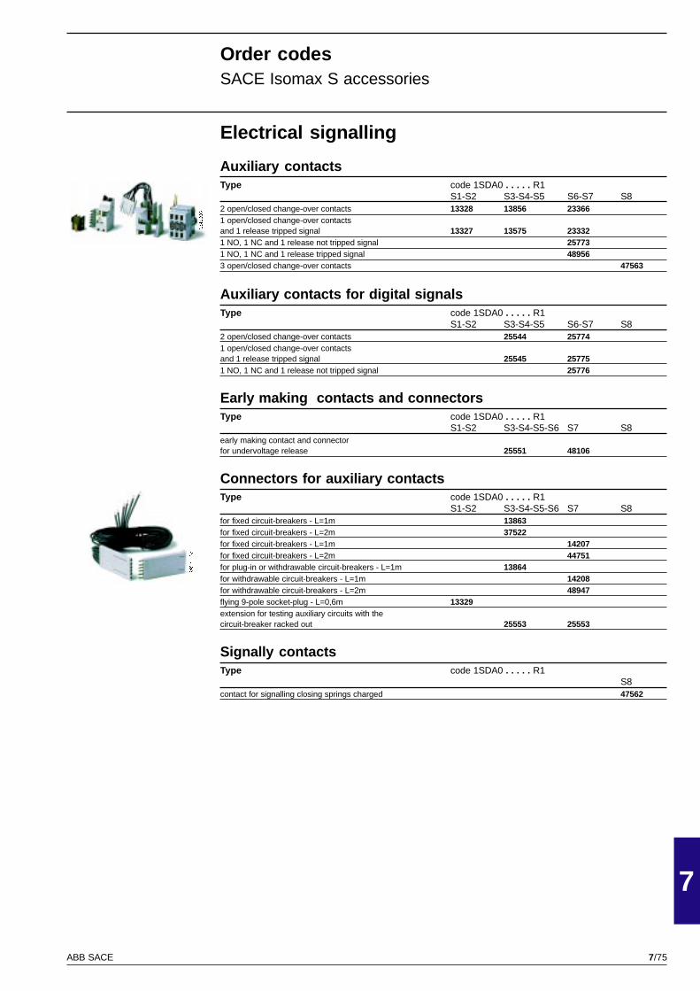
7/75
7
ABB SACE
GSIS9004
GSIS9015
Electrical signalling
Auxiliary contactsType code 1SDA0 . . . . . R1
S1-S2 S3-S4-S5 S6-S7 S82 open/closed change-over contacts 13328 13856 233661 open/closed change-over contactsand 1 release tripped signal 13327 13575 233321 NO, 1 NC and 1 release not tripped signal 257731 NO, 1 NC and 1 release tripped signal 489563 open/closed change-over contacts 47563
Auxiliary contacts for digital signalsType code 1SDA0 . . . . . R1
S1-S2 S3-S4-S5 S6-S7 S82 open/closed change-over contacts 25544 257741 open/closed change-over contactsand 1 release tripped signal 25545 257751 NO, 1 NC and 1 release not tripped signal 25776
Early making contacts and connectorsType code 1SDA0 . . . . . R1
S1-S2 S3-S4-S5-S6 S7 S8early making contact and connectorfor undervoltage release 25551 48106
Connectors for auxiliary contactsType code 1SDA0 . . . . . R1
S1-S2 S3-S4-S5-S6 S7 S8for fixed circuit-breakers - L=1m 13863for fixed circuit-breakers - L=2m 37522for fixed circuit-breakers - L=1m 14207for fixed circuit-breakers - L=2m 44751for plug-in or withdrawable circuit-breakers - L=1m 13864for withdrawable circuit-breakers - L=1m 14208for withdrawable circuit-breakers - L=2m 48947flying 9-pole socket-plug - L=0,6m 13329extension for testing auxiliary circuits with thecircuit-breaker racked out 25553 25553
Signally contactsType code 1SDA0 . . . . . R1
S8contact for signalling closing springs charged 47562
Order codesSACE Isomax S accessories
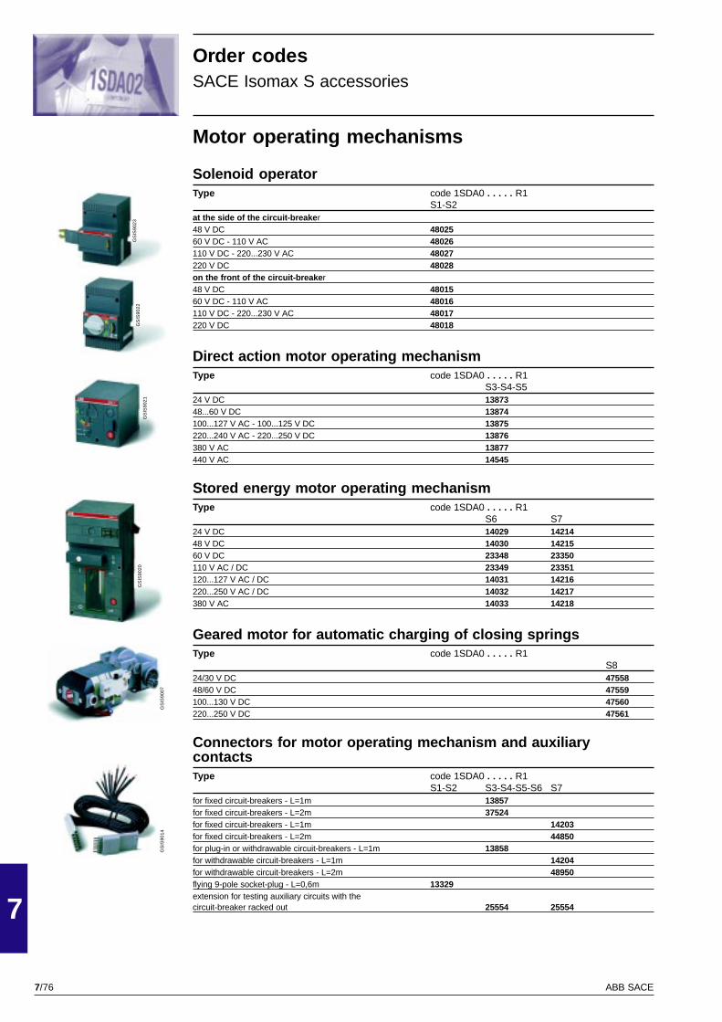
7/76
7
ABB SACE
GS
IS90
22G
SIS
9023
GS
IS90
21G
SIS
9020
GS
IS90
07G
SIS
9014
Motor operating mechanisms
Solenoid operatorType code 1SDA0 . . . . . R1
S1-S2at the side of the circuit-breake r48 V DC 4802560 V DC - 110 V AC 48026110 V DC - 220...230 V AC 48027220 V DC 48028on the front of the circuit-breake r48 V DC 4801560 V DC - 110 V AC 48016110 V DC - 220...230 V AC 48017220 V DC 48018
Direct action motor operating mechanismType code 1SDA0 . . . . . R1
S3-S4-S524 V DC 1387348...60 V DC 13874100...127 V AC - 100...125 V DC 13875220...240 V AC - 220...250 V DC 13876380 V AC 13877440 V AC 14545
Stored energy motor operating mechanismType code 1SDA0 . . . . . R1
S6 S724 V DC 14029 1421448 V DC 14030 1421560 V DC 23348 23350110 V AC / DC 23349 23351120...127 V AC / DC 14031 14216220...250 V AC / DC 14032 14217380 V AC 14033 14218
Geared motor for automatic charging of closing springsType code 1SDA0 . . . . . R1
S824/30 V DC 4755848/60 V DC 47559100...130 V DC 47560220...250 V DC 47561
Connectors for motor operating mechanism and auxiliarycontactsType code 1SDA0 . . . . . R1
S1-S2 S3-S4-S5-S6 S7for fixed circuit-breakers - L=1m 13857for fixed circuit-breakers - L=2m 37524for fixed circuit-breakers - L=1m 14203for fixed circuit-breakers - L=2m 44850for plug-in or withdrawable circuit-breakers - L=1m 13858for withdrawable circuit-breakers - L=1m 14204for withdrawable circuit-breakers - L=2m 48950flying 9-pole socket-plug - L=0,6m 13329extension for testing auxiliary circuits with thecircuit-breaker racked out 25554 25554
Order codesSACE Isomax S accessories
7/77
7
ABB SACE
GSIS9024
GSIS9026
GSIS9008
GSIS9025
GSIS9035
GSIS9010
Operating mechanism and locks
Direct-mounted rotary handle operating mechanismType code 1SDA0 . . . . . R1
S1-S2 S3-S4-S5 S6 S7for fixed/plug-in circuit breakers 13867 14026 14211for withdrawable circuit breakers 13868 14027 14212emergency for fixed or plug-in circuit-breakers 13870 46568 46570
Rotary handle operating mechanism with transmission rodType code 1SDA0 . . . . . R1
S1-S2 S3-S4-S5 S6 S7compartment door, fixed depth for fixedor plug-in circuit-breakers (L= 119,5 mm) 13326compartment door, adjustable depth(Lmax=300 mm) for fixed or plug-in 13869compartment door, adjustable depth(Lmax=300 mm) for withdrawable 50714compartment door, adjustable depth(Lmax=500 mm) for fixed 14028 14213compartment door, adjustable depth(Lmax=500 mm) for withdrawable 50715 50716compartment door, emergency, fixed depthfor fixed or plug-in circuit-breakers (Lmax= 119.5 mm) 45054compartment door, emergency, adjustable depthfor fixed or plug-in circuit-breakers (Lmax= 300 mm) 13871compartment door, emergency, adjustable depthfor fixed circuit-breakers (Lmax= 500 mm) 46569 46572remote transmission rod with adj. depth (Lmax= 180 mm) 25436remote transmission rod with adj. depth (Lmax= 500 mm) 45055 25427
Front flangeType code 1SDA0 . . . . . R1
S3...S5 S6 S7 S8front flange for operating lever mechanism for fixed or plug-in 13889 14035 14227front flange for operating lever mechanism for withdrawable 13890 14036 14228flange for compartment door 45023
Key lock for open positionType code 1SDA0 . . . . . R1
S3...S5 S6-S7 S8for motor operating mechanism - a different key for each cb. 13883 13885for motor operating mechanism - the same key for sets of cbs 13884 13886for motor operating mechanism against manual operation -the same key for each circuit-breaker 36245for front flange / rotary handle -a different key for each circuit-breaker 13881 13881for front flange / rotary handle -the same key for sets of circuit-breakers 13882 13882for front flange 45024key lock type RONIS 43514 43514
Locks
Type Size code 1SDA0 . . . . . R1
compartment door lock for front flangefor locks /crank handle operating mechanism S3-S4-S5-S6-S7 13880padlock device for operating lever S1-S2 13332padlock device on the front of the circuit-breaker S8 45025tamper-proof lock for thermal release S2 36196tamper-proof lock for thermal release S3 25548
Order codesSACE Isomax S accessories

7/78
7
ABB SACE
PSIS9663
PSIS9641
PSIS9642
PSIS9643
PSIS9640
Order codesSACE Isomax S accessories
(*) Order also the relevant EF extended front terminals
Connection terminals
Type code 1SDA0 . . . . . R13 pieces 4 pieces 6 pieces 8 pieces
EF=Extended front terminalsS2 25797 25798S3-S4 23353 23359 13596 13597S5 400 23367 23373 13706 13707S6 630 23379 23389 13920 13921S6 800 23383 23393 13954 13955S7 23399 23396 14079 14080ES=Spreaded extended front terminalsS3-S4 46517 46518 46515 46516S5 47551 47552 47549 47550S6 (1/2 upper kit) 50692 – – –S6 (1/2 lower kit) 50704 – – –S6 – 50693 50688 50689S7 (1/2 upper kit) 50694 – – –S7 (1/2 lowerkit) 50705 – – –S7 – 50695 50690 50691FC Cu=Front terminals for copper cablesS3-S4 23354 23360 13598 13599S5 400 23368 23374 13708 13709S5 630 38769 38770 38767 38768FC CuAl=Front terminals for copper/aluminium cablesS2 (2,5-50 mm2) (*) 50526 50528 36194 36195S2 (35-95 mm2) (*) 50527 50530 25801 25802S3D 100 23355 23361 13600 13601S3 160 - S4 160 (1x95 mm2) 23356 23362 13602 13603S3 250 - S4 250 (1x150 mm2) 23357 23363 20293 20294S5 400 (2x120 mm2) 25766 25765 23295 23296S5 400 (1x240 mm2) 23370 23376 13710 13711S6 630 (2x240 mm2) 23380 23390 13922 13923S6 800 (3x185 mm2) 23384 23394 13956 13957S7 1250 (4x240 mm2) 23387 23397 14081 14082R=Threaded rear terminalsS1 13268 13269S2 13294 13295S3-S4 23352 23365 13606 13607S5 400 23372 23378 13714 13715S5 630 38776 38777 38968 38775S6 23382 23392 13960 13961R Res.Cur.=Threaded rear terminalsfor reasidual current-release mounted belowS3 25543HR/VR=Horizontal or vertical flat-bar rear terminalsS7 23400 23398 14083 14084S8 46578 46579RC = Rear terminals for copper/aluminium cablesS3-S4 (1x120 mm2) 23358 23364 13604 13605S5 400 (1x240 mm2) 23371 23377 13712 13713S6 630 (2x150 mm2) 23381 23391 13924 13925S6 800 (3x240 mm2) 23385 23395 13958 13959
Mechanical interlock across two circuit-breakers
Type code 1SDA0 . . . . . R1horizontal vertical
S3 23330 23331S3X 50524S4 13690 13691S4X 50525S5400/630 43453 43454S6 14024 14025S7 14205 14206S3-S4-S5-S6-S7 (circuit-breaker/fixed part for interlocking) 50093 50093

7/79
7
ABB SACE
PSIS9644
PSIS9638
GSIS9041
GSIS9043
GSIS9045
GSIS9005
GSIS9031
Accessories for electronic releases
Type Model code1SDA0 . . . . . R1
Signalling unit SACE PR010/K S4-S5-S6-S7 48965Signalling unit SACE PR212/K S8 45021Dialogue unit SACE PR212/D-M Modbus + actuator unit SACE PR212/Tfor SACE PR212/P (LSI - LSIG) S4-S5-S6-S7 50718Dialogue unit SACE PR212/D-M Modbus + actuator unit SACE PR212/Tfor SACE PR212/MP (LRIU) S4-S5-S6-S7 50719Dialogue unit SACE PR212/D-L Lon + actuator unit SACE PR212/Tfor SACE PR212/P (LSI - LSIG) S4-S5-S6-S7 50720Dialogue unit SACE PR212/D-L Lon + actuator unit SACE PR212/Tfor SACE PR212/MP (LRIU) S4-S5-S6-S7 50721Dialogue unit SACE PR212/D + Actuator unit SACE PR212/T S8 45020Test unit SACE TT1 S4-S5-S6-S7 37121Test and configuration unit SACE PR010/T S4-S5-S6-S7 48964SACE PR212/CI contactor operating unit (with PR212/MP) S4-S5-S6-S7 50708Current transformer for neutral conductor outside circuit-breaker S4 100 37114Current transformer for neutral conductor outside circuit-breaker S4 160 37115Current transformer for neutral conductor outside circuit-breaker S4 250 37117Current transformer for neutral conductor outside circuit-breaker S5 320 37118Current transformer for neutral conductor outside circuit-breaker S5 400 37119Current transformer for neutral conductor outside circuit-breaker S5 630 37120Current transformer for neutral conductor outside circuit-breaker S6 630 25777Current transformer for neutral conductor outside circuit-breaker S6 800 25778Current transformer for neutral conductor outside circuit-breaker S7 1000 25779Current transformer for neutral conductor outside circuit-breaker S7 1250 25780Current transformer for neutral conductor outside circuit-breaker S7 1600 25781Current transformer for neutral conductor outside circuit-breaker S8 1600 45015Current transformer for neutral conductor outside circuit-breaker S8 2000 45016Current transformer for neutral conductor outside circuit-breaker S8 2500 45017Current transformer for neutral conductor outside circuit-breaker S8 3200 45018X3 connector for relay tripped signal and neutral protectionfor fixed circuit-breaker with PR211/P, PR212/P - LSI S4-S5-S6-S7 13702X3, X4 connectors for relay tripped signal and neutral protectionfor fixed circuit-breaker with PR212/P - LSIG S4-S5-S6-S7 13704X3 connector for relay tripped signal and neutral protectionfor plug-in or withdrawable circuit-breaker with PR211/P, PR212/P - LSI S4-S5-S6-S7 13703X3, X4 connectors for relay tripped signal and neutral protectionfor plug-in or withdrawable circuit-breaker with PR212/P - LSIG S4-S5-S6-S7 13705electrical/mechanical signalling and lock for PR212/P tripped S8 46581
Order codesSACE Isomax S accessories
Insulating terminal covers
Type code 1SDA0 . . . . . R13 poles 4 poles
high for fixedS1 13290 13291S2 13340 13341S3-S4 13695 13696S5 13897 13898S6 14040 14041low for fixed and for moving part of plug-in or withdrawable circuit-breakersS1 13292 13293S2 13342 13343S3-S4 13693 13694S5 13895 13896S6 14038 14039S7 23324 23325
Screws for sealing terminal covers
Type code 1SDA0 . . . . . R1
S1-S2 13344S3-S4-S5-S6-S7 13699
7/80
7
ABB SACE
GSIS9036
GSIS9047
GSIS9037
Conversion kits
from fixed circuit-breaker to moving part of plug-in circuit-breaker
Type code 1SDA0 . . . . . R13 poles 4 poles
S1 13270 13271S2 13296 13297S3-S4 13608 13609S3X 46519 46520S4X 46511 46512S5 400 13716 13717
from fixed circuit-breaker to moving part of withdrawable circuit-breaker
Type code 1SDA0 . . . . . R13 poles 4 poles
S3-S4 13610 13611S3X 46521 46522S4X 46514 46513S5 400 13718 13719S5 630 38778 38779S6 630 / 800 13962 13963S6X 47619 47620S7 23299 14087
from plug-in circuit-breaker to withdrawable circuit-breaker
Type Size code1SDA0 . . . . . R1
Guide for preparing the fixed part of a plug-in circuit-breaker for useas the fixed part of a withdrawable circuit-breaker S3-S4 13692Guide for preparing the fixed part of a plug-in circuit-breaker for useas the fixed part of a withdrawable circuit-breaker S5 13892
Order codesSACE Isomax S accessories
7/81
7
ABB SACE
GS
IS91
23G
SIS
9124
Order codesSACE Isomax S accessories
Fixed parts
Plug-in circuit-breakerType code 1SDA0 . . . . . R1
3 poles 4 polesEF = Extended front terminalsS3 P FP EF 13539 13548S4 P FP EF 13612 13621S5 400 P FP EF 13720 13729FC = Front terminals for copper cablesS1 P FP FC 13272 13274S2 P FP FC 13298 13300S3 P FP FC 13543 13550S4 P FP FC 13616 13625S5 400 P FP FC 13724 13733R = Threaded rear terminalsS1 P FP R 13273 13275S2 P FP R 13299 13540S3 P FP R 13547 13554S4 P FP R 13620 13629S5 400 P FP R 13728 13737
Withdrawable circuit-breaker
Type code 1SDA0 . . . . . R13 poles 4 poles
EF = Extended front terminalsS3 W FP EF 13555 13564S4 W FP EF 13630 13639S5 400 W FP EF 13738 13747S6 W FP EF 13964 13973S7 W FP EF 48951 14097ES = Spreaded extended front terminalsS5 630 W FP ES 38761 38762FC = Front terminals for copper cablesS3 W FP FC 13559 13568S4 W FP FC 13634 13643S5 400 W FP FC 13742 13751R = Threaded rear terminalsS3 W FP R 13563 13572S4 W FP R 13638 13647S5 400 W FP R 13746 13755S5 630 W FP R 38763 38970VR = Vertical flat-bar rear terminalsS5 630 W FP VR 38971 38972S6 W FP VR 13972 13981S7 W FP VR 14096 14105HR = Horizontal flat-bar rear terminalsS6 W FP HR 13968 13977S7 W FP HR 14092 14101
7/82
7
ABB SACE
PSIS9655
PSIS9654
PSIS9653
PSIS9646
GSIS9006
GSIS9009
Accessories for fixed part of plug-in or withdraw-able circuit-breakers
Terminals for the fixed parts of plug-in or withdrawablecircuit-breakers
Type code 1SDA0 . . . . . R13 poles 4 poles
EF = Extended front terminalsS3-S4 13650 13651S5 400 13759 13760S5 630 38780 38781S6 (with terminals mounted below for S6X) 13984 13985S7 14108 14109FC Cu/Al = Front terminals for copper / aluminium cablesS3-S4 13652 13653S5 400 13761 13762R = Threaded rear terminalsS3-S4 13654 13655S5 400 13763 13764S5 630 38969 38782HR = Horizontal flat-bar rear terminalsS6 13986 13987S7 14110 14111VR = Vertical flat-bar rear terminalsS5 630 38763 38784S6 13988 13989S7 14112 14113
Insulating covers for fixed parts
Type code 1SDA0 . . . . . R13 poles 4 poles
S3-S4 13697 13698S5 400 13899 13900
Position contacts
Type Model code1SDA0 . . . . . R1
contacts for signalling circuit-breaker racked out S3-S4-S5-S6-S7 13859contacts for signalling circuit-breaker racked out for digital signals S3-S4-S5-S6-S7 25546contacts for signalling circuit-breaker racked in S3-S4-S5-S6-S7 13860contacts for signalling circuit-breaker racked in for digital signals S3-S4-S5-S6-S7 25547
Lock for fixed part of withdrawable circuit-breakers
Type Model code1SDA0 . . . . . R1
key lock for locking in racked in / out position - different key for each cb. S3-S4-S5-S6-S7 25434key lock for locking in racked in / out position - same key for sets of cb. S3-S4-S5-S6-S7 25435padlock device S3-S4-S5-S6-S7 13872
Order codesSACE Isomax S accessories
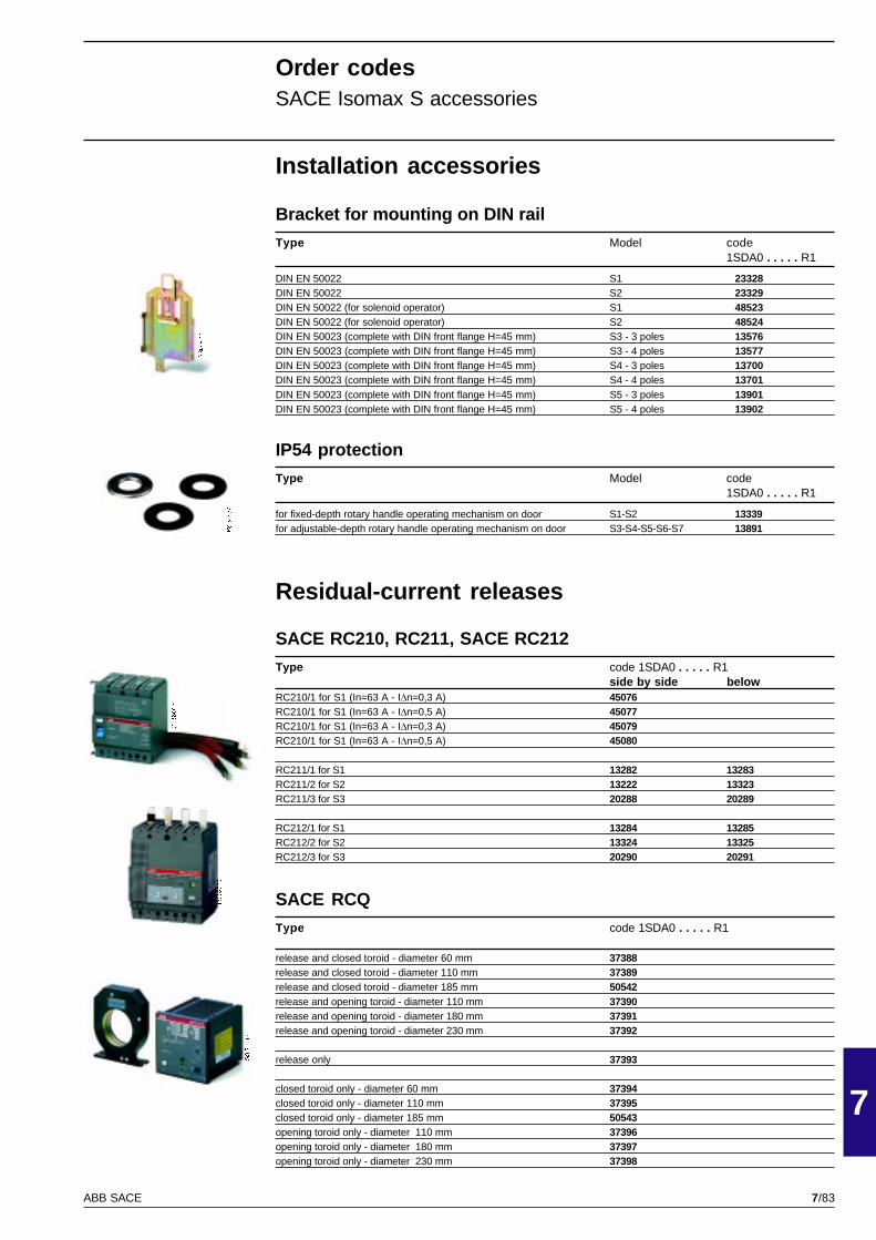
7/83
7
ABB SACE
GSIS9011
PSIS9657
GSIS9027
PSIS9665
GSIS9046
Installation accessories
Bracket for mounting on DIN rail
Type Model code1SDA0 . . . . . R1
DIN EN 50022 S1 23328DIN EN 50022 S2 23329DIN EN 50022 (for solenoid operator) S1 48523DIN EN 50022 (for solenoid operator) S2 48524DIN EN 50023 (complete with DIN front flange H=45 mm) S3 - 3 poles 13576DIN EN 50023 (complete with DIN front flange H=45 mm) S3 - 4 poles 13577DIN EN 50023 (complete with DIN front flange H=45 mm) S4 - 3 poles 13700DIN EN 50023 (complete with DIN front flange H=45 mm) S4 - 4 poles 13701DIN EN 50023 (complete with DIN front flange H=45 mm) S5 - 3 poles 13901DIN EN 50023 (complete with DIN front flange H=45 mm) S5 - 4 poles 13902
IP54 protection
Type Model code1SDA0 . . . . . R1
for fixed-depth rotary handle operating mechanism on door S1-S2 13339for adjustable-depth rotary handle operating mechanism on door S3-S4-S5-S6-S7 13891
Residual-current releases
SACE RC210, RC211, SACE RC212
Type code 1SDA0 . . . . . R1side by side below
RC210/1 for S1 (In=63 A - IDn=0,3 A) 45076RC210/1 for S1 (In=63 A - IDn=0,5 A) 45077RC210/1 for S1 (In=63 A - IDn=0,3 A) 45079RC210/1 for S1 (In=63 A - IDn=0,5 A) 45080
RC211/1 for S1 13282 13283RC211/2 for S2 13222 13323RC211/3 for S3 20288 20289
RC212/1 for S1 13284 13285RC212/2 for S2 13324 13325RC212/3 for S3 20290 20291
SACE RCQ
Type code 1SDA0 . . . . . R1
release and closed toroid - diameter 60 mm 37388release and closed toroid - diameter 110 mm 37389release and closed toroid - diameter 185 mm 50542release and opening toroid - diameter 110 mm 37390release and opening toroid - diameter 180 mm 37391release and opening toroid - diameter 230 mm 37392
release only 37393
closed toroid only - diameter 60 mm 37394closed toroid only - diameter 110 mm 37395closed toroid only - diameter 185 mm 50543opening toroid only - diameter 110 mm 37396opening toroid only - diameter 180 mm 37397opening toroid only - diameter 230 mm 37398
Order codesSACE Isomax S accessories

7/84 ABB SACE

7/85ABB SACE

7/86 ABB SACE

7/87ABB SACE

7/88 ABB SACE

7/89ABB SACE

7/90 ABB SACE


6040
50/0
12 e
nP
rinte
d in
Ital
yT
ipog
rafia
ABB SACE S.p.A.L.V. Breakers DivisionVia Baioni, 3524123 Bergamo - ItalyTel.: +39 035.395.111 - Telefax: +39 035.395.306-433
http://www.abb.com
Due to possible developments of standards as well as of materials,the characteristics and dimensions specified in the present cataloguemay only be considered binding after confirmation by ABB SACE.


