(12) United States Patent (10) Patent No.: US 8.245,511 … · Patrick Sexton, Ypsilanti, MI (US);...
12
USOO8245511 B2 (12) United States Patent (10) Patent No.: US 8.245,511 B2 Cowland et al. (45) Date of Patent: * Aug. 21, 2012 (54) CYLINDER BLOCK MOUNTED PEDESTAL 4.483,147 A * 1 1/1984 Evans et al. ..................... 60/611 AND TURBOCHARGER SYSTEM FOR 4,583,367 A * 4/1986 Kapfer et al. ................ 60.605.3 4,643,137 A 2f1987 Choushi INTERNAL COMBUSTON ENGINE 4,716,735 A * 1/1988 Rufetal. ..................... 60.605.3 5,079,921 A 1/1992 McCandless (75) Inventors: Christopher Cowland, Dexter, MI (US); 5,139,349 A 8, 1992 Nakano Patrick Sexton, Ypsilanti, MI (US); 5,392,604 A * 2/1995 Nikula et al. ...... ... 60.605.3 Christopher Kelly Palazzolo, Ann 5,392,751 A * 2/1995 Matsubara et al. 123,559.1 i. 5,544.486 A 8, 1996 Lu ................................... 60,599 Arbor, MI (US); Anthony William 6,125,799 A 10/2000 Van Son Hudson, Highland, MI (US) 6,305,168 B1 * 10/2001 Furukawa .................... 60.605.1 6,484,683 B2 11/2002 Zielke (73) Assignee: Ford Global Technologies, LLC, 6,915,634 B2 * 7/2005 Dumas et al. ................ 60.605.3 Dearborn, MI (US) 7,043,915 B2 * 5/2006 Anello ......................... 60.605.3 (Continued) (*) Notice: Subject to any disclaimer, the term of this patent is extended or adjusted under 35 U.S.C. 154(b) by 988 days. This patent is Subject to a terminal dis claimer. (21) Appl. No.: 12/145,896 (22) Filed: Jun. 25, 2008 (65) Prior Publication Data US 2009/032O472 A1 Dec. 31, 2009 (51) Int. Cl. F02G 3/00 (2006.01) FO2B33/44 (2006.01) (52) U.S. Cl. ......................................... 60/624; 60/605.3 (58) Field of Classification Search ................. 184/6.11, 184/6.16, 624; 60/605.3; 123/195A, 54.4: 277/591, 594,596,598,637; 41.5/213.1 See application file for complete search history. (56) References Cited U.S. PATENT DOCUMENTS 4.405,138 A * 9/1983 Skrycki ......................... 277/591 4,469,078 A * 9/1984 Speer et al. ................... 123,564 FOREIGN PATENT DOCUMENTS CN 1.01614151 A 12/2009 (Continued) OTHER PUBLICATIONS Office Action of Chinese Application No. 200910 139674.9, Issued Jun. 11, 2012, State Intellectual Property Office of PRC, 2 Pages. Primary Examiner — Thomas Denion Assistant Examiner — Cameron Setayesh (74) Attorney, Agent, or Firm — Julia Voutyras: Alleman Hall McCoy Russell & Tuttle LLP (57) ABSTRACT A turbocharger system for an internal combustion engine includes a turbocharger with a utility pedestal extending between the turbocharger and hard point associated with the cylinder block. The utility pedestal includes a mounting pad for attaching the combined turbocharger and pedestal assem bly to an engine, as well as internal oil and coolant Supply passages for Supplying the turbocharger with coolant and lubricating oil under pressure. 20 Claims, 6 Drawing Sheets
Transcript of (12) United States Patent (10) Patent No.: US 8.245,511 … · Patrick Sexton, Ypsilanti, MI (US);...

USOO8245511 B2
(12) United States Patent (10) Patent No.: US 8.245,511 B2 Cowland et al. (45) Date of Patent: * Aug. 21, 2012
(54) CYLINDER BLOCK MOUNTED PEDESTAL 4.483,147 A * 1 1/1984 Evans et al. ..................... 60/611 AND TURBOCHARGER SYSTEM FOR 4,583,367 A * 4/1986 Kapfer et al. ................ 60.605.3
4,643,137 A 2f1987 Choushi INTERNAL COMBUSTON ENGINE 4,716,735 A * 1/1988 Rufetal. ..................... 60.605.3
5,079,921 A 1/1992 McCandless (75) Inventors: Christopher Cowland, Dexter, MI (US); 5,139,349 A 8, 1992 Nakano
Patrick Sexton, Ypsilanti, MI (US); 5,392,604 A * 2/1995 Nikula et al. ...... ... 60.605.3 Christopher Kelly Palazzolo, Ann 5,392,751 A * 2/1995 Matsubara et al. 123,559.1
i. 5,544.486 A 8, 1996 Lu ................................... 60,599 Arbor, MI (US); Anthony William 6,125,799 A 10/2000 Van Son Hudson, Highland, MI (US) 6,305,168 B1 * 10/2001 Furukawa .................... 60.605.1
6,484,683 B2 11/2002 Zielke (73) Assignee: Ford Global Technologies, LLC, 6,915,634 B2 * 7/2005 Dumas et al. ................ 60.605.3
Dearborn, MI (US) 7,043,915 B2 * 5/2006 Anello ......................... 60.605.3 (Continued)
(*) Notice: Subject to any disclaimer, the term of this patent is extended or adjusted under 35 U.S.C. 154(b) by 988 days. This patent is Subject to a terminal dis claimer.
(21) Appl. No.: 12/145,896
(22) Filed: Jun. 25, 2008
(65) Prior Publication Data
US 2009/032O472 A1 Dec. 31, 2009
(51) Int. Cl. F02G 3/00 (2006.01) FO2B33/44 (2006.01)
(52) U.S. Cl. ......................................... 60/624; 60/605.3 (58) Field of Classification Search ................. 184/6.11,
184/6.16, 624; 60/605.3; 123/195A, 54.4: 277/591, 594,596,598,637; 41.5/213.1
See application file for complete search history.
(56) References Cited
U.S. PATENT DOCUMENTS
4.405,138 A * 9/1983 Skrycki ......................... 277/591 4,469,078 A * 9/1984 Speer et al. ................... 123,564
FOREIGN PATENT DOCUMENTS
CN 1.01614151 A 12/2009
(Continued)
OTHER PUBLICATIONS
Office Action of Chinese Application No. 200910 139674.9, Issued Jun. 11, 2012, State Intellectual Property Office of PRC, 2 Pages.
Primary Examiner — Thomas Denion Assistant Examiner — Cameron Setayesh (74) Attorney, Agent, or Firm — Julia Voutyras: Alleman Hall McCoy Russell & Tuttle LLP
(57) ABSTRACT
A turbocharger system for an internal combustion engine includes a turbocharger with a utility pedestal extending between the turbocharger and hard point associated with the cylinder block. The utility pedestal includes a mounting pad for attaching the combined turbocharger and pedestal assem bly to an engine, as well as internal oil and coolant Supply passages for Supplying the turbocharger with coolant and lubricating oil under pressure.
20 Claims, 6 Drawing Sheets
US 8,245,511 B2 Page 2
U.S. PATENT DOCUMENTS 2009/0078240 A1* 3/2009 Diggs et al. ................ 123,559.1 ck
7,165,402 B2 * 1/2007 Blom ........................... 60.605.3 2009, OO95875 A1 ck 4/2009 Anello ............ ... 248,637 2009/0320469 A1* 12/2009 Palazzolo et al. ............... 60,624
7,784,442 B2 * 8/2010 Lester et al. ............... 123, 1935 2011, 0023800 A1* 2, 2011 Ives etal 123,544 2001/0048062 A1 12, 2001 Murao . . . . . . . . . . . . . . . . . . . . .
2005/0257521 A1 11, 2005 Anello FOREIGN PATENT DOCUMENTS 2007/0056281 A1 3f2007 Arvan et al. .................... 60,598 2007/0175456 A1 8/2007 Tally DE 10218354 A1 11, 2003 2007/0234997 A1 10/2007 Prenger GB 2424450 A 9, 2006 2008/0223329 A1* 9/2008 Preimesberger et al. . 123/195. A * cited by examiner
U.S. Patent Aug. 21, 2012 Sheet 1 of 6 US 8.245,511 B2

U.S. Patent Aug. 21, 2012 Sheet 2 of 6 US 8.245,511 B2
14
56, 18 50 xxy ZN N
S-3 S
38 & YNA-77 N Yé92 S. 28&2 ge 22 S 2x XY 48 % S: kas a

U.S. Patent Aug. 21, 2012 Sheet 3 of 6 US 8.245,511 B2
N S. 2 13 g
es er
TS SLEX
va O s s e-S se e-RSS S isgs
U.S. Patent Aug. 21, 2012 Sheet 4 of 6 US 8.245,511 B2
2zzzza e s
...)
R 1 8 7
& N 4 6 48 as lasAs. 2 ESS LZ An ENSSN-a-3 36 as a
O (As SS s ass
SSNes s SS
9 (SSSSSSSSSS EIS 52 4 77
N at 3 s VN 1 /
H 36 33 2% Was 2. $2
98 4
Figure 4

U.S. Patent Aug. 21, 2012 Sheet 5 of 6 US 8.245,511 B2
C/2SK2, S. S

U.S. Patent Aug. 21, 2012 Sheet 6 of 6 US 8.245,511 B2
Figure 6

US 8,245,511 B2 1.
CYLNDER BLOCK MOUNTED PEDESTAL AND TURBOCHARGER SYSTEM FOR INTERNAL COMBUSTON ENGINE
CROSS REFERENCE TO RELATED APPLICATIONS
None.
BACKGROUND OF THE INVENTION
1. Field of the Invention The present invention relates to a turbocharger system
including not only a turbocharger, but also a mounting ped estal arranged with utilities needed to operate and position the turbocharger. The mounting pedestal is attached to the cylin der block of an engine and is connected with various utilities integrated within a mounting padassociated with the cylinder block.
2. Related Art Turbocharging has been used for a number of years with
internal combustion engines. Although early turbochargers were often cooled primarily by air, as well as by the flow of oil through the turbocharger's bearings, later model turbocharg ers, especially larger turbochargers and those installed in heavy duty engines, generally utilize coolant circulating from the engine's cooling system through the turbo, and then back to the engine's main cooling system.
Turbochargers also require oil Supply and drain utilities to lubricate bearings incorporated within the turbocharger. Needless to say, the provision of a source of coolant and a source of oil, with both being under pressure, as well as draining the oil and coolant from the turbocharger and return ing these fluids separately to the engine, has necessitated a good deal of plumbing. Usually, this plumbing takes the form of external hoses and fittings. Unfortunately, external fluid connections and associated pipes and hoses cause problems becausehoses and fittings are known to leak and are subject to damage accelerated by the high temperatures prevailing within engine compartments. Moreover, aside from durabil ity issues, the need for external plumbing for turbochargers increases the space required by the turbocharger in an already crowded underhood environment.
Turbochargers mounted on engines typically consume a good deal of space for another reason. Because known mounting arrangements are not susceptible to locating the turbocharger close to the engine block, turbochargers must be spaced away from the engine to permit the insertion of the turbochargers' fasteners. U.S. Pat. No. 6,125,799 discloses a bulky mounting system relying in part upon external utilities to the extent that mounting a turbochargers is recommended only on the extreme front or back of an engine. Moreover, other known turbocharger mounting systems increase radi ated noise because of a lack of rigidity and because of the dimensional problems associated with their usage.
It would be desirable to provide a turbocharger, including a mounting system having integral Supply and return passages for coolant and lubricating oil and communicating directly with utility passages within a hard point associated with a cylinder block.
BRIEF DESCRIPTION OF THE INVENTION
According to an aspect of the present invention, a turbo charger system for an internal combustion engine having a cylinder block includes a turbocharger and a utility pedestal extending between the turbocharger and a hard point associ
10
15
25
30
35
40
45
50
55
60
65
2 ated with the cylinder block. The utility pedestal includes a mounting pad for the pedestal and an oil supply passage for conveying lubricating oil under pressure from the cylinder block to the turbocharger. A return oil passage conveys lubri cating oil from the turbocharger to a lubrication system incor porated within the engine. A coolant Supply passage conveys coolant under pressure to the turbocharger, and a coolant return passage, configured at least in part within the utility pedestal, conveys coolant from the turbocharger to a cooling system incorporated within the engine. According to another aspect of the present invention, the coolant return passage may include a passage configured, at least in part, within the engine's cylinder block, as well as within the utility pedestal.
According to another aspect of the present invention a coolant return passage from the turbocharger may be config ured so as to convey the coolant to a mixing chamber within which the coolant from the turbocharger is mixed with cool ant flowing from at least one cylinder head.
According to another aspect of the present invention, a return oil passage from the turbocharger conveys waste oil from the turbocharger to a crankcase Sump without allowing the waste oil to contact moving parts within the engine.
According to another aspect of the present invention, a hard point associated with the cylinder block for mounting the turbocharger includes a generally planar mounting pad con figured on a portion of the cylinder block, with the mounting pad of the utility pedestal having a lower mating Surface matched to the generally planar mounting pad. The cylinder block's mounting pad is configured with lubricating oil and coolant utilities.
According to another aspect of the present invention, a turbocharger's generally planar mounting pad may be con figured upon a cylinder block within a valley defined by the cylinder banks of a V-block engine.
According to yet another aspect of the present invention, the turbocharger pedestal mounting pad of the utility pedestal comprises a number of mounting bosses having fastener bores extending therethrough at an acute angle with respect to a horizontal plane such that fasteners inserted within the bores pass inboard to threaded bores formed in a hard point asso ciated with the cylinder block.
According to another aspect of the present invention, the return, or waste, oil passage extending from the turbocharger and through the utility pedestal is designed to prevent foamed or frothed oil flowing from the turbocharger from impairing engine lubrication. This is accomplished by preventing the waste oil from contacting moving parts within the engine as the oil flows back to the crankcase Sump.
It is an advantage of the present turbocharger system that the turbocharger and pedestal may be assembled at one geo graphic location and installed upon an engine as a single unit at a second geographic location without the need for making external utility connections for lubricating oil and water feeds and drains.
It is another advantage of a turbocharging system accord ing to the present invention that the present turbocharger system, including the turbocharger, a utility pedestal, and a cylinder block mounting pad communicating oil and coolant utilities to the pedestal, functions as a very compact mounting system for attaching the turbocharger system directly to the cylinder block of an internal combustion engine.
It is yet another advantage of a turbocharging system according to the present invention that the noise signature of the turbocharger will be reduced because of the stiffness inherent with the close mounted utility pedestal and cylinder block mounting pad featured in the present invention.

US 8,245,511 B2 3
It is yet another advantage of the present invention that the fasteners used to mount the pedestal to the engine may be accessed without removing portions of the turbocharger.
Other advantages, as well as features of the present inven tion, will become apparent to the reader of this specification.
BRIEF DESCRIPTION OF THE DRAWINGS
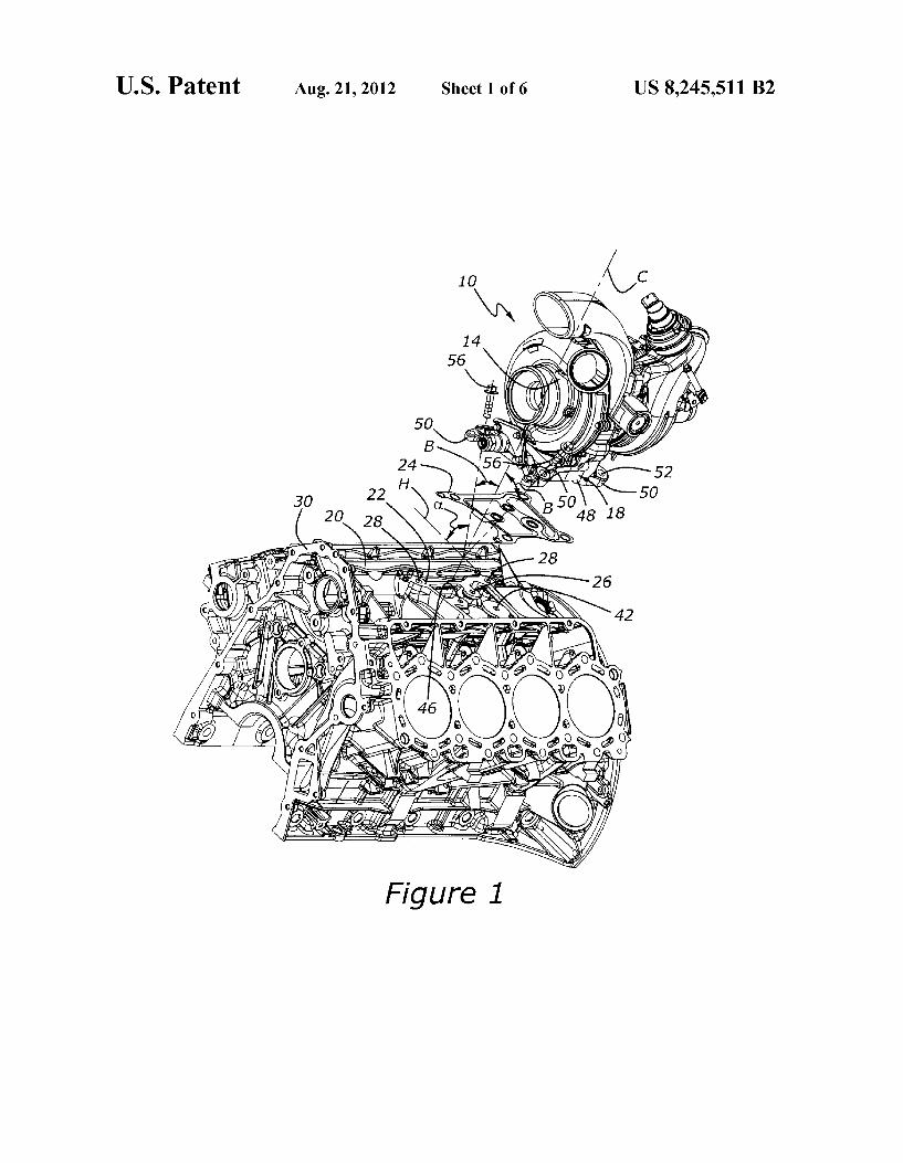
FIG. 1 is an exploded perspective view of an engine having a turbocharger system according to the present invention.
FIG. 2 is an end view, partially cut away, of a portion of an engine having a turbocharger system according to the present invention.
FIG. 3 is a plan view of an engine block showing a turbo charger pedestal mounting pad and utility passages for lubri cating oil and coolant according to an aspect of the present invention.
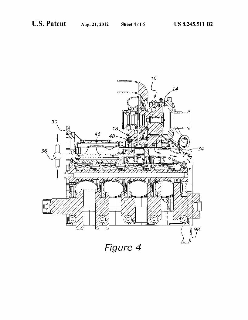
FIG. 4 is a side elevation, partially cut away, of an engine having a turbocharger system according to the present inven tion and showing the routing for several of the utility passages for oil and water according to the present invention.
FIG. 5 is a side perspective view, partially cut away, of an engine having a turbocharger system according to the present invention.
FIG. 6 is a perspective view of a turbocharger mounting hardpoint configured as a plate Suitable for bolting or welding to an engine cylinder block.
DETAILED DESCRIPTION OF THE PREFERRED EMBODIMENTS
As shown in FIG. 1, turbocharger system 10 includes a turbocharger, 14, and a utility pedestal 18. Turbocharger 14 is preferably mounted to utility pedestal 18 before turbocharger 14 is mounted upon an engine. FIG. 1 also shows an engine cylinder block, 30, having a valley, 20, into which turbo charger system 10 is placed upon a hard point, which is illustrated as a generally planar turbocharger mounting pad, 22, which is one piece with cylinder block 30. Utility pedestal 18 provides rigid structural support for turbocharger 14; this helps to reduce unwanted engine noise emissions, as well as reducing unwanted vibration associated with the turbo charger. Those skilled in the art will appreciate in view of this disclosure that the term “hard point', as used herein means eithera structurally rigid mounting location Such as block pad 22 machined into the parent metal of a cylinder block, or a separate pad or bracket, such as that illustrated at 100 in FIG. 6. Mounting pad 100 is intended to be attached to an engine by bolting, or welding, or by Some other Suitable process.
Utility pedestal 18 has a mounting pad, 48, at its lower extremity. Mounting pad 48 includes mounting bosses 50. which have fastener bores 52. Fastener bores 52 extend through mounting bosses 50 and make an acute angle, C., with a horizontal plane, H (FIG. 1). Fastener bores 52 allow the passage of a number of threaded fasteners, 56, which pass through fastenerbores 52 and into threaded bores, 28, formed in generally planar mounting pad 22 of cylinder block 30. Two of threaded bores 28 are shown in FIG. 1. FIG. 1 further shows that mounting bosses 50 are angled so that threaded fasteners or bolts 56 extendinboard into bolt holes 28 formed in mounting pad 22 of cylinder block 30. This geometry is also shown in FIG. 2. As seen in FIG. 2, the width, A, of utility pedestal mounting
pad 48 is less than the overall width, B, of turbocharger 14. This is an added benefit stemming from the angular orienta tion of fastener bores 52, which fortuitously permit turbo charger 14 and utility pedestal 18 to be disassembled as one
10
15
25
30
35
40
45
50
55
60
65
4 unit from the engine without removing portions of the turbo charger assembly. The angles of fastener bores 52 also allow turbocharger 14 to be mounted closer to cylinder block 30, in a vertical direction closer to crankshaft 16. FIG. 2 shows turbocharger 14 nestled in valley 20 between cylinder heads 38 and cylinder block 30.
FIG. 3 shows generally planar mounting pad 22 as being located in the mid-portion of the valley of cylinder block 30. Several of threaded mounting bolt holes 28 are shown. FIGS. 3, 4, and 5 further illustrate lubrication and cooling utilities for turbocharger 14. The first Such utility, oil supply passage 26, is shown as extending through a lubrication port formed within the planar Surface of mounting pad 22 within a boss, 27, and upwardly into utility pedestal 18 from within cylinder block 30.
Coolant Supply passage 42, which is formed in part as a coolant port within a boss, 29, also communicates with the planar Surface of mounting pad 22, as does coolant return 46, which is formed within a third boss, 31. FIG. 5 shows coolant Supply passage 42, which extends into utility pedestal 18 from an engine water jacket, 32. Water leaving turbocharger 14 flows through coolant return passage 46 (FIG. 4) down through utility pedestal 18 and out to the front of engine block 30, wherein the flow is joined with coolant flow from one or more cylinderheads at a combination point 36. Coolant return passage 46 may advantageously be configured as a cored passage within cylinder block 30. Those skilled in the art will appreciate, in view of this disclosure that combination point 36 could be configured as a water outlet or coolant Surge tank or other device for combining coolant flows from more than one source, Such as one or more of the engine's cylinder heads. This combination of flows offers the advantage of mitigating coolant temperature excursions which could oth erwise result from the very warm coolant leaving turbo charger 14.
Because the upper machined surfaces of bosses 27, 29, and 31 corresponding with internal oil Supply passage 26, internal coolant Supply passage 42, and internal coolant return pas sage 46, respectively, are all co-planar with the uppermost Surface of mounting pad 22, all of these utilities may be sealed to utility pedestal 18 with a single gasket 24, which is shown in FIG. 1. Gasket 24 is illustrated as a unitary carrier incor porating a number of integral o-rings for sealing passages 26, 42, and 46. The use of a single gasket carrier, equipped with a number of integral o-ring seals, and coplanar passages, allows a leak-tight seal to be made very quickly and accu rately, without excessive labor or component expense. Those skilled in the art will appreciate in view of this disclosure that a hard point for mounting utility pedestal 18 may be config ured not only within the parent metal of cylinder block 30, but alternatively within adapter 100 having various utility pas sages, as well as threaded fastenerbores akinto the illustrated bores 28 provided in mounting pad 22.
In the event that a separate mounting pad or plate is employed, such as that illustrated at 100 in FIG. 6, a number of fastenerbores, 108, will be provided in the same manner as bores 52. Adapter plate 100 also contains fluid passages 26'. 42', and 46', which perform the functions ascribed to passages 26, 42, and 46, respectively. Plate 100 may be fastened to an engine by means of threaded fasteners extending through bores 104, or by welding or other known methods.
Only the uppermost part of return oil isolation passage 34 within cylinder block 30 is shown in FIG. 3; for more defini tion, one must look to FIG.4, wherein return oil passage 34 is shown as leading to the one end of engine block 30 and down into crankcase Sump 98 in a region in which there are no rotating or moving parts. As noted above, the drainback of

US 8,245,511 B2 5
waste oil from turbocharger 14 to crankcase sump 98 through areas of the engine devoid of moving parts prevents galling or overheating of Such moving parts by preventing contact between parts needing lubrication and temporarily aerated oil. The foregoing invention has been described in accordance
with the relevant legal standards, thus the description is exem plary rather than limiting in nature. Variations and modifica tions to the disclosed embodiment may become apparent to those skilled in the art and fall within the scope of the inven tion. Accordingly the scope of legal protection afforded this invention can only be determined by studying the following claims.
What is claimed is: 1. A turbocharger system for an engine having a cylinder
block, comprising: a turbocharger, and a utility pedestal fastened to the turbocharger and mounted
to a hard point that extends laterally between opposing cylinder banks and is located on a mid-portion of the cylinder block, with said utility pedestal comprising: a mounting pad located at a lower extremity of the ped
estal for mounting the pedestal to the hard point; an internal oil supply passage for conveying lubricating
oil under pressure, from an internal lubrication pas sage in the cylinder block through the hard point, to the turbocharger, and
an internal coolant Supply passage for conveying coolant under pressure, from an internal coolant passage in the cylinder block through the hard point, to the tur bocharger.
2. A turbocharger system according to claim 1, wherein said hard point comprises a generally planar mounting pad configured on a portion of the cylinder block, with the mount ing pad of the utility pedestal having a lower mating Surface matched to the generally planar mounting pad of the hard point.
3. A turbocharger system according to claim 2, wherein said generally planar mounting pad is one piece with the cylinder block.
4. A turbocharger system according to claim 2, wherein said generally planar mounting pad comprises an adapter plate attached to the cylinder block.
5. A turbocharger system according to claim 2, wherein said generally planar mounting pad is configured upon an upper portion of the cylinder block.
6. A turbocharger system according to claim 2, wherein said generally planar mounting pad is configured within a valley defined by the opposing cylinder banks of a V-block engine.
7. A turbocharger system according to claim 1, wherein said pedestal mounting pad comprises a plurality of mounting bosses having fastener bores extending therethrough at an acute angle with respect to a horizontal plane, such that fas teners inserted within the bores pass inboard to threaded bores formed in the hard point.
8. A turbocharger system according to claim 1, further comprising a coolant return passage configured, at least in part, within said utility pedestal for conveying coolant from the turbocharger to a cooling system incorporated within the engine.
9. A turbocharger system according to claim 1, wherein said hard point associated with the cylinder block comprises a generally planar mounting pad configured with a plurality of ported bosses for communicating with said oil Supply passage and said coolant Supply passage.
5
10
15
25
30
35
40
45
50
55
60
65
6 10. A turbocharger system according to claim 1, further
comprising a return oil passage for conveying waste lubricat ing oil through a passage extending through the hard point to a lubrication system incorporated within the engine.
11. A turbocharger system according to claim 1, further comprising a gasket interposed between the pedestal mount ing pad and the hard point, with said gasket comprising a unitary carrier having a plurality of integral o-ring seals.
12. An engine, comprising: a V-block configured cylinder block; a plurality of cylinder heads attached to said cylinder
block, with said cylinder heads and said cylinder block defining a valley between the cylinder heads:
a hard point configured upon said cylinder block within said valley, with said hard point comprising a plurality of ported bosses for furnishing lubricating oil and coolant to a turbocharger, the hard point extending laterally between opposing cylinder heads of the cylinder block; and
a turbocharger mounted upon a utility pedestal extending between the turbocharger and said hard point with said utility pedestal comprising: a mounting pad for the pedestal, with said mounting pad
having a plurality of mounting bosses with fastener bores extending therethrough at an acute angle with respect to a horizontal plane, such that fasteners inserted within the fastener bores pass inboard and into threaded bores formed within the hard point:
an oil Supply passage for conveying lubricating oil under pressure from the cylinder block to the turbocharger, with said oil Supply passage being operatively con nected with one of said ported bosses furnishing lubri cating oil under pressure;
a return oil passage for conveying lubricating oil from the turbocharger to a lubrication system incorporated within the engine; and
a coolant Supply passage for conveying coolant under pressure to the turbocharger, with said coolant Supply passage being operatively connected with one of said ported bosses furnishing coolant under pressure.
13. An engine according to claim 12, further comprising a coolant return passage configured, at least in part, within said utility pedestal for conveying coolant from the turbocharger to a cooling system incorporated within the engine, with said coolant return passage being operatively connected with a ported coolant return boss configured within the hard point.
14. An engine according to claim 12, further comprising a gasket interposed between the pedestal mounting pad and the hard point, with said gasket comprising a unitary carrier hav ing a plurality of integral o-ring seals.
15. An engine, comprising: a V-block configured cylinder block; a plurality of cylinder heads attached to said cylinder
block, with said cylinder heads and said cylinder block defining a valley between the cylinder heads; and
a turbocharger mounted upon a utility pedestal extending between the turbocharger and a hard point, the hard point configured upon said cylinder block within said Valley, with said hard point comprising a plurality of ported bosses for furnishing lubricating oil and coolant to the turbocharger.
16. The engine of claim 15, further comprising: a turbocharger mounted upon a utility pedestal extending
between the turbocharger and said hard point with said utility pedestal having a plurality of mounting bosses with fastener bores extending therethrough at an acute angle with respect to a horizontal plane.

US 8,245,511 B2 7
17. The engine of claim 16, further comprising: fasteners inserted within the fastener bores wherein the
fasteners are directed inboard as they pass through fas tener bores and into threaded bores formed within the hard point associated with the cylinder block.
18. The engine of claim 15, further comprising: an oil Supply passage for conveying lubricating oil under
pressure from the cylinder block to the turbocharger, with said oil Supply passage being operatively con nected with one of said ported bosses furnishing lubri cating oil.
10
8 19. The engine of claim 15, further comprising: a return oil passage for conveying lubricating oil from the
turbocharger to a lubrication system incorporated within the engine.
20. The engine of claim 15, further comprising: a coolant Supply passage for conveying coolant under pres
Sure to the turbocharger, with said coolant Supply pas Sage being operatively connected with one of said ported bosses furnishing coolant.
k k k k k