12” TABLE SAW - The Home Depot · User Manual Read and understand this manual before using...
40
User Manual Read and understand this manual before using machine. 12” TABLE SAW STEEL CITY TOOL WORKS Manual Part No. OR70655 VER. 3.07 C US ® Model Numbers 35635 35636 Shown with optional Industrial Fence and Extension Table
Transcript of 12” TABLE SAW - The Home Depot · User Manual Read and understand this manual before using...

User ManualRead and understand this manual before using machine.
12” TABLE SAW
STEEL CITY TOOL WORKS Manual Part No. OR70655VER. 3.07
C US®
Model Numbers3563535636
Shown with optionalIndustrial Fence
and Extension Table

2
THANK YOU for purchasing your new Steel City Table
Saw. This table saw has been designed, tested, and inspected
with you, the customer, in mind. When properly assembled,
used and maintained, your table saw will provide you with
years of trouble free service, which is why it is backed by
one of the longest machinery warranties in the business.
This table saw is just one of many products in the Steel
City’s family of woodworking machinery and is proof of
our commitment to total customer satisfaction.
At Steel City we continue to strive for excellence each and
every day and value the opinion of you, our customer. For
comments about your table saw or Steel City Tool Works,
please visit our web site at www.steelcitytoolworks.com .

3
TABLE OF CONTENTS
INTRODUCTION
This user manual is intended for use by anyone working with this machine. It should be kept availablefor immediate reference so that all operations can be performed with maximum efficiency and safety.Do not attempt to perform maintenance or operate this machine until you have read and understand theinformation contained in this manual.
The drawings, illustrations, photographs, and specifications in this user manual represent your machineat time of print. However, changes may be made to your machine or this manual at any time with noobligation to Steel City Tool Works.
INTRODUCTION
SECTION 1 Warranty .................................................................................................................................................4
SECTION 2 Product Specifications ............................................................................................................................7
SECTION 3 Accessories and Attachments ................................................................................................................7
SECTION 4 Definition of Terms..................................................................................................................................8
SECTION 5 Feature Identification ..............................................................................................................................9
SECTION 6 General Safety......................................................................................................................................10
SECTION 7 Product Safety ......................................................................................................................................12
SECTION 8 Electrical Requirements...................................................................................................................14-15
SECTION 9 Unpacking & Inventory..........................................................................................................................17
SECTION 10 Assembly ..............................................................................................................................................19
SECTION 11 Adjustments ..........................................................................................................................................21
SECTION 12 Operations ............................................................................................................................................25
SECTION 13 Maintenance .........................................................................................................................................29
SECTION 14 Troubleshooting ....................................................................................................................................30
SECTION 15 Parts List..........................................................................................................................................32-37

4
WARRANTY
STEEL CITY TOOL WORKS5 YEAR LIMITED WARRANTY
Steel City Tool Works, LLC (“SCTW”) warrants all “STEEL CITY TOOL WORKS” machinery to befree of defects in workmanship and materials for a period of 5 years from the date of the original retailpurchase by the original owner. SCTW will repair or replace, at its expense and at its option, anySCTW machine, machine part, or machine accessory which in normal use has proven to be defective,provided that the customer returns the product, shipping prepaid, to an authorized service center withproof of purchase and provides SCTW with a reasonable opportunity to verify the alleged defect byinspection. This warranty does not apply to defects due directly or indirectly to misuse, abuse,negligence, accidents, or lack of maintenance, or to repairs or alterations made or specifically authorizedby anyone other than SCTW. Normal wear components are also excluded under this coverage. Everyeffort has been made to ensure that all SCTW machinery meets the highest quality and durabilitystandards. We reserve the right to change specifications at any time due to our commitment tocontinuous improvement of the quality of our products.
EXCEPT AS SET FORTH ABOVE, SCTW MAKES NO EXPRESS OR IMPLIED REPRESENTA-TIONS OR WARRANTIES WITH RESPECT TO ITS MACHINERY, OR ITS CONDITION,MERCHANTABILITY, OR FITNESS FOR ANY PARTICULAR PURPOSE OR USE. SCTWFURNISHES THE ABOVE WARRANTIES IN LIEU OF ALL OTHER WARRANTIES, EXPRESSOR IMPLIED, INCLUDING THE WARRANTIES OF MERCHANTABILITY AND FITNESS FOR APARTICULAR PURPOSE, WHICH ARE HEREBY SPECIFICALLY DISCLAIMED.
SCTW SHALL NOT BE LIABLE FOR ANY (A) SPECIAL, INDIRECT, INCIDENTAL, PUNITIVEOR CONSEQUENTIAL DAMAGES, INCLUDING WITHOUT LIMITATION LOSS OF PROFITS,ARISING FROM OR RELATED TO THIS WARRANTY, THE BREACH OF ANY AGREEMENT ORWARRANTY, OR THE OPERATION OR USE OF ITS MACHINERY, INCLUDING WITHOUTLIMITATION DAMAGES ARISING FROM DAMAGE TO FIXTURES, TOOLS, EQUIPMENT,PARTS OR MATERIALS, DIRECT OR INDIRECT LOSS CAUSED BY ANY OTHER PARTY, LOSSOF REVENUE OR PROFITS, FINANCING OR INTEREST CHARGES, AND CLAIMS BY ANYTHIRD PERSON, WHETHER OR NOT NOTICE OF SUCH POSSIBLE DAMAGES HAS BEENGIVEN TO SCTW; (B) DAMAGES OF ANY KIND FOR ANY DELAY BY OR FAILURE OF SCTWTO PERFORM ITS OBLIGATIONS UNDER THIS AGREEMENT; OR (C) CLAIMS MADE ASUBJECT OF A LEGAL PROCEEDING AGAINST SCTW MORE THAN ONE (1) YEAR AFTERSUCH CAUSE OF ACTION FIRST AROSE.
The validity, construction and performance of this Warranty and any sale of machinery by SCTW shallbe governed by the laws of the Commonwealth of Pennsylvania, without regard to conflicts of laws pro-visions of any jurisdiction. Any action related in any way to any alleged or actual offer, acceptance orsale by SCTW, or any claim related to the performance of any agreement including without limitationthis Warranty, shall take place in the federal or state courts in Allegheny County, Pennsylvania.
STEEL CITY TOOL WORKS

5
WARRANTY CARDName ________________________________________________
Street _______________________________________________
Apt. No. ______________________________________________
City_________________________ State ______ Zip __________
Phone Number_________________________________________
E-Mail________________________________________________
Product Description:_____________________________________
Model No.: ___________________________________________
Serial No. _____________________________________________
The following information is given on a voluntary basisand is strictly confidential.
1. Where did you purchase your STEEL CITY machine?
Store: ____________________________________________
City:______________________________________________
2. How did you first learn of Steel City Tool Works?
___ Advertisement ___ Mail Order Catalog
___ Web Site ___ Friend
___ Local Store Other_______________________
3. Which of the following magazines do you subscribe to?
___ American Woodworker ___ American How-To
––– Cabinetmaker ___ Family Handyman
___ Fine Homebuilding ___ Fine Woodworking
___ Journal of Light Construction ___ Old House Journal
___ Popular Mechanics ___ Popular Science
___ Popular Woodworking ___ Today’s Homeowner
___ WOOD ___ Woodcraft
___ WOODEN Boat ___ Woodshop News
___ Woodsmith ___ Woodwork
___ Woodworker ___ Woodworker’s Journal
___ Workbench Other_________________
4. Which of the following woodworking / remodeling shows doyou watch?
___ Backyard America ___ The American Woodworker
___ Home Time ___ The New Yankee Workshop
___ This Old House ___ Woodwright’s Shop
Other__________________________________________
5. What is your annual household income?
___ $20,000 to $29,999 ___ $30,000 to $39,999
___ $40,000 to $49,999 ___ $50,000 to $59,999
___ $60,000 to $69,999 ___ 70,000 to $79,999
___ $80,000 to $89,999 ___ $90,000 +
6. What is your age group?
___ 20 to 29 years ___ 30 to 39 years
___ 40 to 49 years ___ 50 to 59 years
___ 60 to 69 years ___ 70 + years
7. How long have you been a woodworker?
___ 0 to 2 years ___ 2 to 8 years
___ 8 to 20 years ___ over 20 years
8. How would you rank your woodworking skills?
___ Simple ___ Intermediate
___ Advance ___ Master Craftsman
9. How many Steel City machines do you own? _____________
10. What stationary woodworking tools do you own? Check all that apply.
___ Air Compressor ___ Band Saw
___ Drill Press ___ Drum Sander
___ Dust Collection ___ Horizontal Boring Machine
___ Jointer ___ Lathe
___ Mortiser ___ Panel Saw
___ Planer ___ Power Feeder
___ Radial Arm Saw ___ Shaper
___ Spindle Sander ___ Table Saw
___ Vacuum Veneer Press ___ Wide Belt Sander
Other____________________________________________
11. Which benchtop tools do you own? Check all that apply.
___ Belt Sander ___ Belt / Disc Sander
___ Drill Press ___ Band Saw
___ Grinder ___ Mini Jointer
___ Mini Lathe ___ Scroll Saw
___ Spindle / Belt Sander Other______________________
12. Which portable / hand held power tools do you own? Check all that apply.
___ Belt Sander ___ Biscuit Jointer
___ Dust Collector ___ Circular Saw
___ Detail Sander ___ Drill / Driver
___ Miter Saw ___ Orbital Sander
___ Palm Sander ___ Portable Thickness Planer
___ Saber Saw ___ Reciprocating Saw
___ Router Other_______________________
13. What machines / accessories would you like to see added to theSTEEL CITY line?
____________________________________________________
____________________________________________________
14. What new accessories would you like to see added?
____________________________________________________
____________________________________________________
15. Do you think your purchase represents good value?
___Yes ___ No
16. Would you recommend STEEL CITY products to a friend?
___ Yes ___ No
17. Comments:
____________________________________________________
____________________________________________________
____________________________________________________
____________________________________________________
____________________________________________________
!C
UT
HE
RE

6
Steel City Tool WorksP.O. Box 10529
Murfreesboro, TN 37129
PLACESTAMPHERE
FOLD ON DOTTED LINE
FOLD ON DOTTED LINE

7
PRODUCT SPECIFICATIONS
Blade Diameter 12”
Arbor Diameter 1”
Maximum Depth of Cut 4”
Maximum Thickness at 45 cut 2-7/8”
Table in front of Saw 12”
Maximum Width of Dado 13/16”
Maximum Diameter of Dado 10”
Dust Port Diameter 4”
Table Height 33-7/8”
Table Size(with extension) 29” D x 44” W
Table Size(without extension) 29” D x 22” W
Blade Speed 4200
Motor Model #35635 Model #35636
Type Induction Induction
HorsePower 7.5 HP 5 HP
Amps 18 24.5
Voltage 230 V 230 V
Phase Three Single
Hertz 60 60
RPM 3450 3450
Product Dimensions
Footprint 22-1/4” X 22-1/4”
Length 44-1/2”
Width 35”
Height 40”
Weight 400 lbs.
Shipping Dimensions
Carton Type Box on Pallet
Length 32”
Width 34”
Height 41”
Gross Weight 430 lbs.
ACCESSORIES AND ATTACHMENTS
There are a variety of accessories available for your Steel City Product. For more information onany accessories associated with this and other machines, please contact your nearest Steel Citydistributor, or visit our website at: www.steelcitytoolworks.com.

8
DEFINITION OF TERMS
Anti-Kickback Fingers – A safety device attached tothe blade guard and splitter assembly designed to mini-mize the chance of a workpiece being thrown back dur-ing a cutting operation.
Arbor – The shaft on which the blade or accessory cut-ting-tool is mounted.
Bevel Cut – The operation of making any cut with theblade set at an angle other than 90 degrees.
Compound Cut – The operation of making both abevel and a miter cut at one time.
Crosscut – The operation of making a cut across thegrain or width of a workpiece.
Dado – A non-through cut that produces a squarenotch. A dado is typically from 1/8-in. to 13/16-in. wide.A dado requires a special set of blades, not includedwith this table saw.
Featherboard – An accessory device that can be madeor purchased to help guide or hold down a workpieceduring cutting operations.
Freehand – A very dangerous operation of making acut without using the fence or miter gauge in a cuttingoperation. Freehand cuts must never be performed ona Table Saw.
Gum, Pitch or Resin – A sticky, sap based residue thatcomes from wood products.
Heeling – The misalignment of the blade to the miterslots; when the blade is not parallel to the miter slots.
Kerf – The material removed from the workpiece by theblade during any cutting operation.
Kickback – When the workpiece is thrown back towardthe operator at a high rate of speed during a cuttingoperation.
Miter Cut – The operation of making a cut using themiter gauge at any angle other than zero degrees.
Push Stick – An accessory device that can be madeor purchased to help push the workpiece through theblade. A push stick is used to keep the operator’shands away from the blade when ripping a narrowworkpiece.
Rabbet – A square notch in the edge of the workpiece.
Rip Cut – The operation of making a cut with the grainor down the length of the workpiece.
Saw Blade Path – The area that is directly in line withthe blade, including area over, under, behind and infront of it.
Set of the Saw Blade – The distance that the tips ofthe saw blade are angled outwards from the thicknessof the blade. The set of the saw blade teeth allows forthe blade body to pass safely through all cuts.
Table/Work Area – The total surface of the top of thetable saw on which the workpiece rests while set-up orcutting operations are being performed.

9
FEATURE IDENTIFICATION
A) Switch
B) Blade Height Adjustment Handwheel
C) Bevel Adjustment Handwheel
D) Blade Height Lock Knob
E) Bevel Lock Knob
F) Miter Gauge
G) Blade Guard Assembly
H) Motor Cover
(shown with an optional fence and extension table)
E
C
B
D
A
H
FG

10
TO AVOID serious injury and damage to the machine,read and follow all Safety and Operating Instructionsbefore assembling and operating this machine.
This manual is not totally comprehensive. It does notand can not convey every possible safety and opera-tional problem which may arise while using thismachine. The manual will cover many of the basic andspecific safety procedures needed in an industrial envi-ronment.
All federal and state laws and any regulations havingjurisdiction covering the safety requirements for use ofthis machine take precedence over the statements inthis manual. Users of this machine must adhere to allsuch regulations.
Below is a list of symbols that are used to attract yourattention to possible dangerous conditions.
This is the international safety alert symbol. It is usedto alert you to potential personal injury hazards. Obeyall safety messages that follow this symbol to avoidpossible injury or death.
Indicates an imminently hazardous situation which, ifnot avoided, WILL result in death or serious injury.
Indicates a potentially hazardous situation which, if notavoided, COULD result in death or serious injury.
Indicates a potentially hazardous situation, if not avoid-ed, MAY result in minor or moderate injury. It may alsobe used to alert against unsafe practices.
CAUTION used without the safety alert symbol indi-cates a potentially hazardous situation which, if notavoided, may result in property damage.
This symbol is used to alert the user to useful informa-tion about proper operation of the machine.
GENERAL SAFETY
DANGER
NOTICE
CAUTION
Exposure to the dust created by power sanding, saw-ing, grinding, drilling and other construction activitiesmay cause serious and permanent respiratory orother injury, including silicosis (a serious lung dis-ease), cancer, and death. Avoid breathing the dust,and avoid prolonged contact with dust. The dustmay contain chemicals known to the State ofCalifornia to cause cancer, birth defects or otherreproductive harm.
2. ALWAYS wear eye protection. Any machine canthrow debris into the eyes during operations,which could cause severe and permanent eyedamage. Everyday eyeglasses are NOT safetyglasses. ALWAYS wear Safety Goggles (thatcomply with ANSI standard Z87.1) when operat-ing power tools.
WARNING
WARNING
CAUTION
Some examples of these chemicals are:
• Lead from lead-based paints.
• Crystalline silica from bricks, cement and othermasonry products.
• Arsenic and chromium from chemically-treatedlumber.
Always operate tool in well ventilated area and pro-vide for proper dust removal. Use a dust collectionsystem along with an air filtration system wheneverpossible. Always use properly fitting NIOSH/OSHAapproved respiratory protection appropriate for thedust exposure, and wash exposed areas with soapand water.
1. To avoid serious injury and damage to the machine,read the entire User Manual before assembly andoperation of this machine.
!
!
!
!
!
WARNING!
WARNING!

11
4. ALWAYS wear a NIOSH/OSHA approved dustmask to prevent inhaling dangerous dust or air-borne particles.
8. AVOID a dangerous working environment. DONOT use electrical tools in a damp environmentor expose them to rain or moisture.
9. CHILDPROOF THE WORKSHOP AREA byremoving switch keys, unplugging tools from theelectrical receptacles, and using padlocks.
3. ALWAYS wear hearing protection. Plain cotton isnot an acceptable protective device. Hearingequipment should comply with ANSI S3.19Standards.
5. ALWAYS keep the work area clean, well lit, andorganized. DO NOT work in an area that has slip-pery floor surfaces from debris, grease, and wax.
6. ALWAYS unplug the machine from the electricalreceptacle before making adjustments, changingparts or performing any maintenance.
7. AVOID ACCIDENTAL STARTING. Make sure thatthe power switch is in the “OFF” position beforeplugging in the power cord to the electricalreceptacle.
WARNING!
WARNING!
WARNING!
WARNING!
11. DO NOT FORCE the machine to perform an opera-tion for which it was not designed. It will do a saferand higher quality job by only performing operationsfor which the machine was intended.
12. DO NOT stand on a machine. Serious injury couldresult if it tips over or you accidentally contact anymoving part.
13. DO NOT store anything above or near the machine.
14. DO NOT operate any machine or tool if under theinfluence of drugs, alcohol, or medication.
15. EACH AND EVERY time, check for damaged partsprior to using any machine. Carefully check allguards to see that they operate properly, are notdamaged, and perform their intended functions.Check for alignment, binding or breakage of allmoving parts. Any guard or other part that is dam-aged should be immediately repaired or replaced.
16. Ground all machines. If any machine is suppliedwith a 3-prong plug, it must be plugged into a 3-contact electrical receptacle. The third prong isused to ground the tool and provide protectionagainst accidental electric shock. DO NOT removethe third prong.
17. Keep visitors and children away from any machine.DO NOT permit people to be in the immediate workarea, especially when the machine is operating.
18. KEEP protective guards in place and in workingorder.
19. MAINTAIN your balance. DO NOT extend yourselfover the tool. Wear oil resistant rubber soled shoes.Keep floor clear of debris, grease, and wax.
20. MAINTAIN all machines with care. ALWAYS KEEPmachine clean and in good working order. KEEP allblades and tool bits sharp.
21. NEVER leave a machine running, unattended. Turnthe power switch to the OFF position. DO NOTleave the machine until it has come to a completestop.
22. REMOVE ALL MAINTENANCE TOOLS from theimmediate area prior to turning the machine ON.
23. SECURE all work. When it is possible, use clampsor jigs to secure the workpiece. This is safer thanattempting to hold the workpiece with your hands.
24. STAY ALERT, watch what you are doing, and usecommon sense when operating any machine. DONOT operate any machine tool while tired or underthe influence of drugs, alcohol, or medication. Amoment of inattention while operating power toolsmay result in serious personal injury.
10. DO NOT use electrical tools in the presence offlammable liquids or gasses.

12
25. USE ONLY recommended accessories. Use ofincorrect or improper accessories could cause seri-ous injury to the operator and cause damage to themachine. If in doubt, DO NOT use it.
26. THE USE of extension cords is not recommendedfor 230V equipment. It is better to arrange theplacement of your equipment and the installedwiring to eliminate the need for an extension cord.If an extension cord is necessary, refer to the chartin the Grounding Instructions section to determinethe minimum gauge for the extension cord. Theextension cord must also contain a ground wire andplug pin.
27. Wear proper clothing, DO NOT wear loose clothing,gloves, neckties, or jewelry. These items can getcaught in the machine during operations and pullthe operator into the moving parts. Users mustwear a protective cover on their hair, if the hair islong, to prevent it from contacting any moving parts.
28. SAVE these instructions and refer to them frequent-ly and use them to instruct other users.
29. Information regarding the safe and proper operationof this tool is also available from the followingsources:
Power Tool Institute1300 Summer AvenueCleveland, OH 44115-2851www.powertoolinstitute.org
National Safety Council1121 Spring Lake DriveItasca, IL 60143-3201
American National Standards Institute25West 43rd. St, 4th FloorNew York, NY. 10036ANSI 01.1 Safety RequirementsFor Woodworking MachinesWWW.ANSI.ORG
U.S. Department of Labor RegulationsOSHA 1910.213 RegulationsWWW.OSHA.GOV
1. Serious personal injury may occur if normal safetyprecautions are overlooked or ignored. Accidentsare frequently caused by lack of familiarity or failureto pay attention. Obtain advice from supervisor,instructor, or another qualified individual who isfamiliar with this machine and its operations.
2. Every work area is different. Always consider safe-ty first, as it applies to your work area. Use thismachine with respect and caution. Failure to do socould result in serious personal injury and damageto the machine.
3. Prevent electrical shock. Follow all electrical andsafety codes, including the National Electrical Code(NEC) and the Occupational Safety and HealthRegulations (OSHA). All electrical connections andwiring should be made by qualified personnel only.
6. Safety decals are on this machine to warn anddirect you to how to protect yourself or visitors frompersonal injury. These decals MUST be maintainedso that they are legible. REPLACE decals that arenot legible.
7. DO NOT leave the unit plugged into the electricaloutlet. Unplug the unit from the outlet when not inuse and before servicing, performing maintenancetasks, or cleaning.
8. ALWAYS turn the power switch “OFF” beforeunplugging the table saw.
PRODUCT SAFETY
4. TO REDUCE the risk of electrical shock. DONOT use this machine outdoors. DO NOTexpose to rain or moisture. Store indoors in adry area.
WARNING!
5. STOP using this machine, if at any time you experi-ence difficulties in performing any operation.Contact your supervisor, instructor or machine serv-ice center immediately.
9. DO NOT handle the plug or table saw withwet hands.
WARNING!
10. USE accessories only recommended by SteelCity.
11. DO NOT pull the table saw by the power cord.NEVER allow the power cord to come in contactwith sharp edges, hot surfaces, oil or grease.
12. DO NOT unplug the table saw by pulling on thepower cord. ALWAYS grasp the plug, not thecord.

13
21. DO NOT cut a workpiece that is too large for youto safely handle. Use an outfeed table or workstandto properly support the piece.
22. DO NOT use the rip fence as a guide when cross-cutting
23. BE MINDFUL of flaws in the wood. Cutting awarped or twisted board along the rip fence can getpinched between the fence and the blade, causinga kickback
24. ALWAYS remove cut off pieces and scraps fromthe table before starting the saw
25. NEVER start the machine with the workpieceagainst the blade
26. NEVER perform freehand operations. Use eitherthe fence or miter gauge to position and guide theworkpiece through the blade.
27. ALWAYS use a pushstick for ripping narrow work-pieces
28. NEVER have any part of your body in line with thepath of the saw blade. If a kickback occurs withyou directly in front of the blade, a serious injurycan occur.
29. NEVER attempt to free a stalled blade without firstturning the machine off and disconnecting the sawfrom the power source.
30. DO NOT reach over or behind a rotating saw blade.
15. ENSURE that the machine sits firmly on the floorbefore using. If the machine wobbles or is unstable,correct the problem by using shims or blocks priorto operation.
16. KEEP saw blade sharp and clean. Failure to do sogreatly increases friction, decreases cut quality, andincreases the possibility of a kickback
17. MAKE CERTAIN the saw blade is parallel with themiter slots and with the rip fence. A blade that isnot aligned parallel can cause the workpiece to bepinched between the blade and the fence causingburning or kickbacks.
18. ALWAYS use blade guard on all through cuts. This will help prevent the cut from closing on theback of the saw blade. The blade guard also hasanti-kickback fingers which minimize the chanceof a workpiece being thrown back during a cuttingoperation.
19. ALWAYS push the workpiece past the blade. DONOT release a workpiece until it is past the bladeand removed from the saw.
20. DO NOT execute a cut when you do not havecomplete control of the situation.
13. REPLACE a damaged cord immediately. DO NOTuse a damaged cord or plug. DO NOT use if thetable saw is not operating properly, or has beendamaged, left outdoors or has been in contact withwater.
14. DO NOT use the table saw as a toy. DO NOT usenear or around children.

14
ELECTRICAL REQUIREMENTS
TO PREVENT electrical shock, follow all electrical andsafety codes, including the National Electrical Code(NEC) and the Occupational Safety and HealthRegulations (OSHA). All electrical connections andwiring should be made by qualified personnel only.
TO REDUCE the risk of electrical shock, DO NOT usemachine outdoors. DO NOT expose to rain or mois-ture. Store indoors in a dry area.
DO NOT connect the machine to the power sourcebefore you have completed the set up process.
DO NOT connect the machine to the power source untilinstructed to do so.
This motor in this machine is designed to run at 230V.Power connections must be made at the switch. For connections, refer to wiring photo Fig. A.
On your incoming power line:
1. The White Lead connects to terminal L1.
2. The Black Lead connects to terminal L3.
3. The Ground Wire connects to the groundingterminal.
Notice: Some Table Saws will be equipped with a junc-tion box located near the base of the saw. If this is thecase with your model saw, all power connections will bemade in the junction box instead of at the switch. Thejunction box will have markings for L1, L3, and Ground.Following the steps above, connect the wires to theirproper terminals.
WHITE LEAD TOL1 TERMINAL
BLACK LEAD TOL3 TERMINAL
GROUND WIRETO GROUNDING
TERMINAL
USE THIS SETUP FOR MODEL NUMBER 35636 ONLY
Fig. A

15
ELECTRICAL REQUIREMENTS
The motor in this machine is designed for 230 Volt 3phase use. Power connections for this must be madeat the switch. For connections refer to wiring photoFig. B.
On your incoming power line:
1. The White Lead connects to terminal L1
2. The Black Lead connects to terminal L2
3. The Red Lead connects to terminal L3
4. The Ground Line connects to the groundingterminal
After making these connections, turn the saw on tomake sure that the arbor is turning towards the opera-tor. If the arbor rotates in the proper direction theconnection is complete. If the arbor rotates away fromthe operator, switch any 2 lines with one another tochange direction of rotation.
Notice: Some Table Saws will be equipped with a junc-tion box located near the base of the saw. If this is thecase with your model saw, all power connections will bemade in the junction box instead of at the switch. Thejunction box will have terminals for L1, L2, L3, andGround. Following the steps above, connect the wiresto their proper terminals.
USE THIS SETUP FOR MODEL NUMBER 35635 ONLY
TO PREVENT electrical shock, follow all electrical andsafety codes, including the National Electrical Code(NEC) and the Occupational Safety and HealthRegulations (OSHA). All electrical connections andwiring should be made by qualified personnel only.
TO REDUCE the risk of electrical shock, DO NOT usemachine outdoors. DO NOT expose to rain or mois-ture. Store indoors in a dry area.
DO NOT connect the machine to the power sourcebefore you have completed the set up process.
DO NOT connect the machine to the power source untilinstructed to do so.
RED LEAD TOL3 TERMINAL
GROUND WIRETO GROUNDING
TERMINAL
WHITE LEAD TOL1 TERMINAL
BLACK LEAD TOL2 TERMINAL
Fig. B

16
GROUNDING INSTRUCTIONS
This machine MUST BE GROUNDED while in use toprotect the operator from electric shock.
In the event of a malfunction or breakdown, GROUND-ING provides the path of least resistance for electriccurrent and reduces the risk of electric shock. The plugMUST be plugged into a matching electrical receptaclethat is properly installed and grounded in accordancewith ALL local codes and ordinances.
If a plug is provided with your machine DO NOT modifythe plug. If it will not fit your electrical receptacle, havea qualified electrician install the proper connections tomeet all electrical codes local and state. All connectionsmust also adhere to all of OSHA mandates.
IMPROPER ELECTRICAL CONNECTION of the equip-ment-grounding conductor can result in risk of electricshock. The conductor with the green insulation (with orwithout yellow stripes) is the equipment-grounding con-ductor. DO NOT connect the equipment-grounding con-ductor to a live terminal.
Check with a qualified electrician or service personnel ifyou do not completely understand the groundinginstructions, or if you are not sure the tool is properlygrounded.
PLUGS/RECEPTACLES
• Electrocution or fire could result if this machine isnot grounded properly or if the electrical configura-tion does not comply with local and state electricalcodes.
• MAKE CERTAIN the machine is disconnectedfrom power source before starting any electricalwork.
• MAKE SURE the circuit breaker does not exceedthe rating of the plug and receptacle.
MINIMUM RECOMMENDED GAUGE FOR EXTENSION CORDS (AWG)
230 VOLT OPERATION ONLY
25’ LONG 50’ LONG 100’ LONG
0 to 6 Amps 16 AWG 16 AWG 14 AWG
6 to 8 Amps 16 AWG 16 AWG 12 AWG
8 to 12 Amps 14 AWG 14 AWG 10 AWG
12 to 15 Amps 12 AWG 12 AWG 10 AWG
15 to 20 Amps 10 AWG 10 AWG Notrecommended
EXTENSION CORDS
To reduce the risk of fire or electrical shock, use theproper gauge of extension cord. When using anextension cord, be sure to use one heavy enough tocarry the current your machine will draw.
The smaller the gauge-number, the larger the diameterof the extension cord is. If in doubt of the proper size ofan extension cord, use a shorter and thicker cord. Anundersized cord will cause a drop in line voltage result-ing in a loss of power and overheating.
USE ONLY a 3-wire extension cord that has a 3-pronggrounding plug and a 3-pole receptacle that accepts themachine’s plug.
If you are using an extension cord outdoors, be sure itis marked with the suffix “W-A” (“W” in Canada) to indi-cate that it is acceptable for outdoor use.
Make certain the extension cord is properly sized, andin good electrical condition. Always replace a worn ordamaged extension cord immediately or have itrepaired by a qualified person before using it.
Protect your extension cords from sharp objects, exces-sive heat, and damp or wet areas.
Depending on your model table saw, the motor suppliedwith your machine is either a 230 volt, single phasemotor (Model 35636) or a 230 volt, three phase motor(Model 35635). Never connect the green or ground wireto a live terminal.
A machine with a 230 volt plug should only be connect-ed to an outlet having the same configuration as theplug.
WARNING!
WARNING!
WARNING!
CAUTION!

17
• The machine is heavy, two people are required tounpack and lift.
• Use a safety strap to avoid tip over when liftingmachine.
Check shipping carton and machine for damage beforeunpackaging. Carefully remove packaging materials,parts and machine from shipping carton. To remove thecarton from the inside of the saw cabinet, crank thehandwheel to lower the arbor to its lowest position.Always check for and remove protective shipping mate-rials around motors and moving parts. Lay out all partson a clean work surface.
Remove any protective materials and coatings from all
UNPACKING & INVENTORY
of the parts and the table saw. The protective coatingscan be removed by spraying WD-40 on them and wip-ing it off with a soft cloth. This may need redone sever-al times before all of the protective coatings areremoved completely.
After cleaning, apply a good quality paste wax to anyunpainted surfaces. Make sure to buff out the waxbefore assembly.
Compare the items to inventory figures; verify that allitems are accounted for before discarding the shippingbox.
If any parts are missing, do not attempt to plug in thepower cord and turn “ON” the machine. The machineshould only be turned “ON” after all the parts have beenobtained and installed correctly. For missing parts,contact Steel City at 1-877-SC4-TOOL.
A) Blade Wrenches
B) Blade GuardMounting BracketAssembly
C) Miter Gauge
D) Handwheel
E) Lock Knob
F) 12mm Wrench
A D
E
C
B
F
WARNING!
WARNING!

18
G) Left and RightExtension Wings
H) Blade GuardAssembly
GH

19
ASSEMBLY
INSTALLATION AND LEVELING
Final location for the saw must be level, dry, well light-ed, and have enough room to allow movement aroundthe saw with long pieces of wood stock.
Level the saw front to back and side to side, using acarpenter’s level placed on the table. Use shims underthe corners, if necessary, but make sure the saw isstable before being placed into service.
MAKE CERTAIN THAT THE SAW IS DISCONNECT-ED FROM THE POWER SOURCE.
Fig. 2
EXTENSION WING ASSEMBLY
1. Attach extension wing to the table with three hexhead bolts, three lock washers, and three flat wash-ers. Snug but do not tighten.
2. Slide extension wings toward the front edge of thesaw table until two edges are flush. Make certainthat the beveled edge of the wing faces towards thefront of the saw.
HANDWHEEL ASSEMBLY
Fig. 3
1. Line up the key on the shaft with the keyway in thehandwheel (A), and slide the handwheel onto theshaft. SEE FIG. 3.
2. Tighten the set screw on the handwheel hubsecurely to hold in place.
3. Install center lock knob (B) by inserting into centerhole in the shaft and threading in a clockwisedirection.
3. Using a straight edge (A), align the extension wingsto the saw table and tighten the hex head bolts.SEE FIG. 2.
4. Repeat Steps 1-3 for the other wing.
A
B
A
WARNING!

20
BLADE GUARD ASSEMBLY
1. Place the closed loop end of the cable (A) with theattached blade guard wrench over the blade guardshaft. SEE FIG. 4.
2. Place a lock washer onto the threaded portion ofthe blade guard shaft.
3. Thread blade guard shaft into rear trunnion throughopening at rear of saw.
4. Tighten blade guard shaft. The blade guard posthas a flat detent to accommodate wrenches.
5. Place upper and lower bracket assembly in theupright position and snug two set screws justenough to hold in place. Do not tighten firmly atthis time.
6. Insert front tab of blade guard splitter through insertopening in the table. Loosen the hex head screw(A) already installed at the factory and insert thefront tab of the blade guard splitter. The tab is heldin place between the flat washer and bracket.Finger tighten only at this time. SEE FIG. 5.
7. Attach rear tab of blade guard splitter to the upperblade guard bracket with two hex head bolts (B).Finger tighten only at this time.
8. A blade will need to be installed before final adjust-ment can be made.
Fig. 4 Fig. 5
A
B
A
MAKE CERTAIN THAT THE SAW IS DISCONNECT-ED FROM THE POWER SOURCE.
1. Raise the blade arbor fully, set the bevel angle atzero, and lock the arbor by tightening the lock knobin the middle of the handwheel.
2. Remove the arbor nut and flange.
3. Place the blade on the arbor shaft, making sure theteeth point down at the front of the saw. Replacethe flange (A) and the arbor nut (B). SEE FIG. 6.
4. Using the wrenches provided, securely tighten thearbor nut. Remove the wrenches.
INSTALLING BLADE
Fig. 6
B
A
WARNING!
MAKE CERTAIN THAT THE SAW IS DISCONNECT-ED FROM THE POWER SOURCE.
WARNING!

21
ADJUSTMENTS
1. Raise blade guard away from table and hold anti-kickback fingers (A) away from table surface.SEE FIG. 7.
2. Using an accurate straight edge (B), align thesplitter with the saw blade. Be sure the straightedge rests against body of saw blade and not sawteeth.
3. When saw blade is aligned with the splitter, care-fully tighten the hex cap bolt (C) on the bracketassembly inside the saw.
4. Make sure the splitter is level with the table andapproximately 1/8” above the table before tighten-ing the hardware on the rear of the blade guardassembly. This space between the splitter and thetable keeps the splitter from binding on the tablewhen the blade is tilted to 45°.
5. When saw blade is aligned with the splitter, lowerthe blade, and tighten all hardware.
6. Check alignment again after tightening hardware.Adjust if necessary.
MAKE CERTAIN THAT THE SAW IS DISCONNECT-ED FROM THE POWER SOURCE.
ALIGNING BLADE GUARDAND SPLITTER
Fig. 7
A
C
B
TABLE INSERT ADJUSTMENT
1. Lower blade completely.
2. Place the open end of the insert under the splitterand lower the insert into the opening.
3. Adjust the table insert flush with the table by turningfour leveling screws and using a straight edge. SEEFIG. 8.
Fig. 8
Fig. 9
MITER GAUGE OPERATION1. Operate miter gauge by loosening lock knob (A)
and turning miter body (B) to desired angle. Tomove gauge beyond index stops of 45° and 90°,flip down stop (C). SEE FIG. 9.
2. Adjust index stops by turning one of three adjust-ment screws (D).
Note: Always make test cuts. Do not rely solely onmiter gauge indictor marks.
B
A
D
D
C
WARNING! MAKE CERTAIN THAT THE SAW IS DISCONNECT-ED FROM THE POWER SOURCE.
WARNING!

22
1. To raise or lower the saw blade, loosen the lockknob (A) in the middle of the handwheel and turnthe handwheel (B) on the saw front until desiredheight is reached. Tighten lock knob. SEE FIG. 10.
2. To tilt the saw blade, loosen lock knob (C), turnhandwheel on the right of the saw cabinet (D) untildesired angle is obtained, then tighten lock knob.
BLADE RAISING ANDTILTING MECHANISM
Fig. 10
ON/OFF SWITCHThe on and off switch is thermally protected. If thesaw motor is overloaded, or a momentary interruptionof electrical current is sensed, the saw will shut off.Allow a few minutes for the saw to cool down and resetby pushing the off button (A). SEE FIG. 11.
Using extension cords can cause a loss in power toyour machine. It is best if the saw is plugged directlyinto an outlet on a dedicated circuit. If using an exten-sion cord, refer to chart in the Grounding Instructionssection to determine proper gauge and length.
Fig. 11
A
BD
C
A
BLADE ALIGNMENTBlade alignment with the table is adjusted at the factory.After a period of use, or after moving the saw to an-other location, the blade may no longer be aligned withthe table. To check and align the blade:
1. Raise the blade guard (A) up and out of the way ofthe blade. SEE FIG. 12.
2. Unlock fence and move away from the blade so asto expose the right miter slot (B).
3. Choose a tooth on the far side of the blade anddirectly over the back side of the insert. Mark thetooth with a marker. Measure the distance from theside of the blade to the right miter slot edge using acombination square (C). Make sure to measurebetween the teeth, not on the tooth.
4. Rotate the blade toward the front so that themarked tooth is just above the front side of theinsert. Measure the distance from the side of theblade to the right miter slot edge. The two measure-ments should be the same.
Fig. 12
A
C
B
MAKE CERTAIN THAT THE SAW IS DISCONNECT-ED FROM THE POWER SOURCE.
WARNING!

23
Fig. 13
A
ADJUSTING 45° AND 90°POSITIVE STOPSThe stops have been adjusted at the factory. After aperiod of use, or, after moving the saw to anotherlocation, the stops may no longer be set properly.To check and adjust the stops:
MAKE CERTAIN THAT THE SAW IS DISCONNECT-ED FROM THE POWER SOURCE.
1. Raise the saw blade to its maximum height usingthe handwheel.
2. Set the blade at 90 degrees to the table by turningthe blade tilting handwheel clockwise as far as itwill go.
Fig. 14
Fig. 15
3. Place a square on the table and check to see thatthe blade is at a 90° angle to the table. Make suresquare is not touching a blade tooth. SEE FIG. 14.
4. If blade is not at 90 degrees, open the motor coverdoor, loosen lock nut (A) and turn adjusting stopscrew (B) on the front trunnion (C) in or out. Theadjusting stop screw (B) should stop against thefront trunnion bracket when the blade is 90 degreesto the table. SEE FIG. 15.
5. If they are not the same, loosen the four sockethead cap screws (A) that hold the table to the base.Two are shown in Fig. 13; the other two are on theback corners of the machine. SEE FIG. 13.
6. Make the needed adjustments and tighten the fourhex socket cap screws firmly.
7. Check the alignment once again after tighteninghardware.
WARNING!

24
MOUNTING RAILS, FENCEAND EXTENSION TABLEWith the extension wings properly aligned, the rail andfence assembly can now be mounted to the saw.See the Owner’s Manual for the Fence AssemblyInstructions. This will address the mounting of the railsand fence.
Fig. 16
5. Tighten locknut (A)
6. Set the blade at 45 degrees to the table by turningthe blade tilting handwheel counterclockwise as faras it will go. Place a square on the table.SEE FIG. 16.
7. If the blade is not at 45 degrees, loosen lock nut(D) and turn adjusting stop screw (E) on the fronttrunnion (C) in or out. The adjusting stop screw (E)should stop against the front trunnion bracket whenthe blade is 45 degrees to the table. SEE FIG 15.
8. Check the accuracy of the pointer on the anglescale and adjust if necessary.
25
OPERATIONS
MAKE CERTAIN THAT THE SAW IS DISCONNECT-ED FROM THE POWER SOURCE.
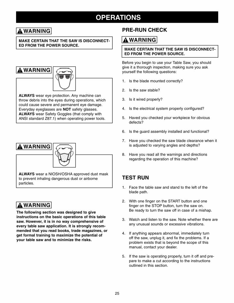
ALWAYS wear eye protection. Any machine canthrow debris into the eyes during operations, whichcould cause severe and permanent eye damage.Everyday eyeglasses are NOT safety glasses.ALWAYS wear Safety Goggles (that comply withANSI standard Z87.1) when operating power tools.
The following section was designed to giveinstructions on the basic operations of this tablesaw. However, it is in no way comprehensive ofevery table saw application. It is strongly recom-mended that you read books, trade magazines, orget formal training to maximize the potential ofyour table saw and to minimize the risks.
PRE-RUN CHECK
Before you begin to use your Table Saw, you shouldgive it a thorough inspection, making sure you askyourself the following questions:
1. Is the blade mounted correctly?
2. Is the saw stable?
3. Is it wired properly?
4. Is the electrical system properly configured?
5. Haved you checked your workpiece for obviousdefects?
6. Is the guard assembly installed and functional?
7. Have you checked the saw blade clearance when itis adjusted to varying angles and depths?
8. Have you read all the warnings and directionsregarding the operation of this machine?
TEST RUN
1. Face the table saw and stand to the left of theblade path.
2. With one finger on the START button and onefinger on the STOP button, turn the saw on.Be ready to turn the saw off in case of a mishap.
3. Watch and listen to the saw. Note whether there areany unusual sounds or excessive vibrations.
4. If anything appears abnormal, immediately turnoff the saw, unplug it, and fix the problems. If aproblem exists that is beyond the scope of thismanual, contact your dealer.
5. If the saw is operating properly, turn it off and pre-pare to make a cut according to the instructionsoutlined in this section.
ALWAYS wear a NIOSH/OSHA approved dust maskto prevent inhaling dangerous dust or airborneparticles.
MAKE CERTAIN THAT THE SAW IS DISCONNECT-ED FROM THE POWER SOURCE.
WARNING!
WARNING!
WARNING!
WARNING!
WARNING!

26
BLADE SELECTIONChoosing the correct blade for the job is essential forthe safe and efficient use of your table saw. Ignoringthis important step could result in damage to the sawand serious injury to the operator. Below are the mostcommon saw blades and their uses.
1. Rip Blade: Used for cutting with the grain.Typically, 12” rip blades have between 18-40 teethand large gullets to allow for large chip removal.SEE FIG. 19.
Fig. 19
2. Cross-cut Blade: Used for cutting across the grain.12” cross-cut blades have between 60-80 teeth anda shallow gullet. SEE FIG. 20.
Fig. 20
3. Combination Blade: Used for cutting with andacross the grain. A compromise between a rip bladeand a cross-cut blade, a 12” combination blade willtypically have between 40-50 teeth. SEE FIG. 21.
Fig. 21
4. Thin-kerf blade: Most types of saw blades areavailable in a thin-kerf style. Designed primarily tominimize stock waste, thin-kerf blades are used inconjunction with a blade stabilizer to reduce bladewobble. Note: Many blade guards/splitters arethicker than many thin-kerf blades. Make sure thatthe stock will pass by the guard/splitter beforebeginning a cut.
5. Dado Blades: There are two types of dado blades:stack and wobble. Stack dadoes involve more set-up time, but they provide a superior finish cut whencompared to a wobble dado. Dado blades requireuse of accessory dado table insert.
6. Moulding Heads: A moulding head is a cutterheadthat attaches to the arbor and holds individualmoulding knives. They are very dangerous andrequire training beyond the scope of this manual.
This section on blade selection is by no means compre-hensive. Always follow the saw blade manufacturer’srecommendations to assure safe and efficient operationof your table saw.
27
CROSSCUTTINGCrosscutting means cutting across the grain of thewood. In wood products without grain (i.e. MDF,particleboard), crosscutting simply means cutting acrossthe width of the stock.
Crosscuts are made with the miter gauge. There aretwo miter gauge slots in the table top. Use the one thatworks best for the piece being crosscut. To make acrosscut using the miter gauge:
1. Inspect the board for soundness. You do notnecessarily need a square edge to crosscut withaccuracy.
2. Inspect the miter gauge. Is it properly set and tight?
3. Move the rip fence completely out of the way.
4. Turn on the saw and allow it to come to full speed.
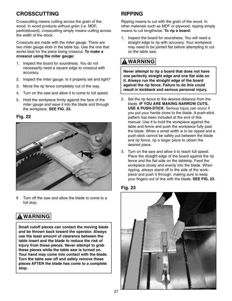
5. Hold the workpiece firmly against the face of themiter gauge and ease it into the blade and throughthe workpiece. SEE FIG. 22.
Fig. 22
6 Turn off the saw and allow the blade to come to afull stop.
Small cutoff pieces can contact the moving bladeand be thrown back toward the operator. Alwaysuse the least amount of clearance between thetable insert and the blade to reduce the risk ofinjury from these pieces. Never attempt to grabthese pieces while the table saw is turned on.Your hand may come into contact with the blade.Turn the table saw off and safely remove thesepieces AFTER the blade has come to a completestop.
RIPPINGRipping means to cut with the grain of the wood. Inother materials such as MDF or plywood, ripping simplymeans to cut lengthwise. To rip a board:
1. Inspect the board for soundness. You will need astraight edge to rip with accuracy. Your workpiecemay need to be jointed flat before attempting to cuton the table saw.
2. Set the rip fence to the desired distance from theblade. IF YOU ARE MAKING NARROW CUTS,USE A PUSH-STICK. Serious injury can occur ifyou put your hands close to the blade. A push-stickpattern has been included at the end of thismanual. Use it to hold the workpiece against thetable and fence and push the workpiece fully pastthe blade. When a small width is to be ripped and apush-stick cannot be safely put between the bladeand rip fence, rip a larger piece to obtain thedesired piece.
3. Turn on the saw and allow it to reach full speed.Place the straight edge of the board against the ripfence and the flat side on the tabletop. Feed theworkpiece slowly and evenly into the blade. Whenripping, always stand off to the side of the work-piece and push it through, making sure to keepyour fingers out of line with the blade. SEE FIG. 23.
Never attempt to rip a board that does not haveone perfectly straight edge and one flat side onit. Always run the straight edge of the boardagainst the rip fence. Failure to do this couldresult in kickback and serious personal injury.
Fig. 23
WARNING!
WARNING!

28
Fig. 24
Stand out of the line of potential kickback. Holdthe workpiece firmly against the fence and table.Do not allow your fingers to get close to theblade! Do not reach over the blade to off-load theworkpiece.
DADO OPERATIONSIn addition to its ability to rip and crosscut lumber,the table saw is also an invaluable tool for creating avariety of dadoes. These non-through cuts can becreated with specially-designed stacking or wobblingdado blades.
Never allow hands or arms to be above or behindthe saw blade. Should kickback occur, the handsand arms can be pulled into the saw blade.Serious injury will result.
Never perform a through cut operation with adado blade. A dado blade is designed to makenon-through cuts only. Failure to follow thesedierctions could result in serious injury.
Dado operations present very real hazardsrequiring proper procedures to avoid seriousinjury. The chance of kickback is always greaterwhen dado blades are used so extra precautionsmust be used. Any movement of the stock awayfrom the fence can cause kickback. Be certainthat stock is flat and straight. Failure to followthese warnings could result in serious personalinjury.
Always use push sticks, featherboards, push pad-dles and other safety accessories whenever poss-ible to increase safety and control during opera-tions which require the blade guard and splitter tobe removed from the saw. ALWAYS replace theblade guard after dadoing is complete.
Proper dado operations will differ depending on theblade system you choose. Consult the instructionsincluded with your dado blades for directions regardingattachment and adjustment. To use a dado blade:
1. Remove the table insert, splitter guard, and regularsaw blade.
2. Attach and adjust the dado blade system as recom-mended in the dado blade’s instructions.
3. Install the dado table insert.
4. Raise the blade system up to the desired depth ofthe dado. Make sure the dado blade will not cutthrough the workpiece.
5. Reconnect the saw to the power source.
6. If dadoing along the length of your workpiece,adjust the distance between the fence and theinside edge of the blade to suit your needs. Whencutting across the wood grain, use the miter gaugeas a guide while dadoing. Remember: Never usethe fence as a stop in conjunction with your mitergauge.
7. Using a scrap piece as a test piece, switch on thesaw and take a pass over the dado blade.
8. If the cut is satisfactory, repeat with your finishstock.
9. Avoid taking too deep a cut in a single pass. Makeincremental cuts to avoid kickback.
MAKE CERTAIN THAT THE SAW IS DISCONNECT-ED FROM THE POWER SOURCE.
Do not stand directly behind the workpiece whenripping. SEE FIG. 24.
WARNING!
WARNING!
WARNING!WARNING!
WARNING!
WARNING!

29
MAINTENANCE
This table saw requires very little maintenance otherthan minor lubrication and cleaning. The following sec-tions detail what will need to be done in order to assurecontinued operation of your saw.
LUBRICATION
The table saw has sealed lubricated bearings in themotor housing and the arbor assembly that do notrequire any additional lubrication from the operator.
Use a wire brush to clean off the worm gears andtrunnions and apply a white lithium grease to keepthem lubricated.
CLEANINGKeep the inside of the cabinet clear of saw dust andwood chips. With the table saw unplugged, vacuum outthe inside of the cabinet or blow out the inside with anair hose. Be sure to use air pressure no higher than50 P.S.I. as high pressure air may damage insulation. The tabletop is an unfinished metal surface that, overtime, will accumulate rust if not properly cared for.When the table saw is not in use, keep a light coat ofWD-40 on the table top as this will help prevent rustfrom occurring. If rust has already accumulated on thetable, use WD-40 and a fine steel wool to get rid of therust. Using a quality paste wax on the tabletop andwings is a good preventative measure to help preventrust from forming.
Be sure to wear protective eyewear and dust maskwhen cleaning out the cabinet of the saw.
CHANGING BELTS
MAKE CERTAIN THAT THE SAW IS DISCONNECT-ED FROM THE POWER SOURCE.
Fig. 1
1. Lower the blade to its lowest point.
2. Loosen one hex cap bolts (A). SEE FIG. 1.
3. Take the tension off of the belts (B) by lifting up onthe motor.
4. Remove the belts from the arbor and motor pulleys.
5. Replace and tension the belts. The weight of themotor should apply enough tension to the belts.Tighten the hex cap bolts.
6. Check the belt tension after the saw has been usedfor a few hours. Adjust as necessary.
7. Use only Steel City replacement parts.
B
A
MAKE CERTAIN THAT THE SAW IS DISCONNECT-ED FROM THE POWER SOURCE.
WARNING!
WARNING!
WARNING!

30
TROUBLESHOOTING GUIDE
This section covers the most common processing problems encountered in sawing and what to do about them.Do not make any adjustments until the table saw is unplugged from the power source and moving parts have cometo a complete stop.
PROBLEM LIKELY CAUSE(S) SOLUTION
1. Overload tripped. 1. Allow motor to cool and reset by pushing off switch.2. Saw unplugged from wall or motor. 2. Check all plug connections.3. Fuse blown or circuit breaker tripped. 3. Replace fuse or reset circuit breaker.4. Cord damaged. 4. Replace cord.
1. Stops not adjusted correctly. 1. Check blade with square and adjust stops.2. Angle pointer not set accurately. 2. Check blade with square and adjust pointer.3. Miter gauge out of adjustment. 3. Adjust miter gauge.
1. Fence not aligned with blade. 1. Check and adjust fence.2. Warped wood. 2. Select another piece of wood.3. Excessive feed rate. 3. Reduce feed rate.4. Splitter not aligned with blade. 4. Align splitter with blade.
1. Dull blade. 1. Sharpen or replace blade.2. Blade mounted backwards. 2. Properly mount blade.3. Gum or pitch on blade. 3. Remove blade and clean.4. Incorrect blade for cut. 4. Change blade to correct type.5. Gum or pitch on table. 5. Clean table.
1. Extension cord too light or too long. 1. Replace with adequate size cord.2. Low shop voltage. 2. Contact your local electric company.3. Motor not wired for correct voltage. 3. Refer to motor junction box.
1. Stand on uneven floor. 1. Reposition on flat, level surface.2. Damaged saw blade. 2. Replace saw blade.3. Bad V-belts. 3. Replace V-belts.4. Bent pulley. 4. Replace pulley.5. Improper motor mounting. 5. Check and adjust motor.6. Loose hardware. 6. Tighten hardware.7. Loose set screw in pulley. 7. Tighten set screw.
1. Guide rails or extension wing not installed 1. Reassemble guide rails, refer to fence manual.correctly.
2. Guide of rip fence not adjusted properly. 2. Adjust guides, refer to fence manual.
1. Rip fence out of alignment. 1. Align rip fence with miter slot and blade.2. Splitter not aligned with blade. 2. Align splitter with blade.3. Feeding stock without rip fence. 3. Install and use rip fence.4. Splitter not in place. 4. Install and use splitter (with guard).5. Dull blade. 5. Replace blade.6. Letting go of material before it is past blade. 6. Push material all the way past blade before releasing work.7. Anti-kickback fingers dull. 7. Replace or sharpen anti-kickback fingers.
1. Sawdust and debris in raising and tilting 1. Clean and grease.mechanisms.
Saw stops orwill not start.
Does not makeaccurate 45° or 90°cuts.
Material binds bladewhen ripping.
Saw makesunsatisfactorycuts.
Blade does notcome up to speed.
Saw vibratesexcessively.
Rip fence bindson guide rails.
Material kicked backfrom blade.
Blade does not raiseor tilt freely.

31
u NOTES u

32
PARTS

33
KEY PARTNO. NO. DESCRIPTION QTY.
1 OR70450 Miter Gage Lock Knob 1
2 OR70451 Miter Gage Body 1
3 OR90381 Hex Nut M5 3
4 OR70452 Pointer 1
5 OR70453 Stop 1
6 OR93812 Set Screw M5 x 5 1
7 OR93813 Special Pin 3mm x 6mm 1
8 OR93814 Pan Head Screw M5 x 20 3
9 OR70457 Guide Bar 1
10 OR70458 Guide Washer 1
11 OR91805 Flat Head Screw M6 x 8 1
12 OR91789 Set Screw 1/4 x 3/8 4
13 OR70598 Table Insert 1
14 OR70599 Table 1
15A OR70600 Extension Wing, LEFT 11” 1
15B OR73636 Extension Wing, RIGHT 11” 1
16 OR93815 Hex Socket Cap Screw 7/16 x 1 1/2 6
17 OR93816 Lock Washer 7/16 6
18 OR93817 Flat Washer 7/16 x 25mm x 3mm 10
19 OR70601 Motor Cover 1
20 OR90235 Hex Nut M6 1
21 OR70467 Handle 1
22 OR70468 Foam Strip 1
23 OR90059 Flat Washer M6 2
24 OR93818 Spring 1
25 OR93819 Hex Head Screw M6 x 50 1
26 OR90060 Flat Washer 1/4 4
27 OR90070 Lock Washer 1/4 4
28 OR90071 Hex Nut 1/4 4
29A OR70602 Tilt Scale 1
29B OR93823 Rivet 2
30 OR70473 Dust Hose Adapter 1
31 OR93821 Tap Screw M5 x 10 8
32 OR90460 Carriage Bolt 1/4 x 3/4 4
33 OR70475 Switch Plate 1
34A OR70603 Switch (Magnetic, 7.5HP, 3PH, 230V) 1
34B OR70476 Switch (Magnetic, 5HP, 1PH, 230V) 1
35 OR93822 Screw 3/16 x 3/4 2
36 OR90462 Flat Washer M5 2
37A OR70604 Power Cord (Switch to Motor, 7.5HP, 3ph, 230V) 1
37B OR70605 Power Cord (Switch to Motor, 5HP, 1ph, 230V) 1
38 OR70479 Cable Strain Relief 1
39 OR70480 Cable Bushing 1
40A OR70484 Nameplate 1
40B OR93823 Rivet 4
41A OR70481 Warning Label 1
41B OR70482 Kickback Warning Label 1
41C OR70483 Ear & Eye Protection Label 1
42 OR70606 Cabinet 1
43 OR93824 Hex Socket Cap Screw 7/16 x 3/4 4
44A OR70306 Serial Number Plate ( 7.5HP, 3PH, 230V) 1
44B OR70307 Serial Number Plate ( 5HP, 1PH, 230V) 1
45 OR70609 Dust Chute 1
46 OR70490 Junction Box Assembly (Not Shown) 1
47 OR70594 Tool Hook 3
KEY PARTNO. NO. DESCRIPTION QTY.

34

35
KEY PARTNO. NO. DESCRIPTION QTY.
101 OR70610 Arbor Nut 1
102 OR70611 Arbor Flange 1
103 OR70612 Blade 1
104 OR70613 Arbor 1
105 OR70495 Key 5mm x 5mm x 44mm 2
106 OR93887 Ball Bearing 2
107 OR93826 Wave Washer 2
108 OR70614 Spacer 2
109 OR91789 Set Screw 1/4 x 3/8 6
110 OR70615 Arbor Pulley 1
111 OR93884 Hex Socket Cap Screw 3/8 - 16 x 1 3/4 1
112 OR93883 Key 5mm x 5mm x 50mm 1
113 OR90647 Lock Washer 3/8 10
114 OR70616 Arbor Bracket 1
115 OR70617 Spanner Nut 1
116 OR93876 Hex Nut 3/4 1
117 OR93882 Spring Pin 6mm x 50mm 1
118 OR93881 Key 1/4 x 1/4 x 75mm 1
119 OR93816 Flat Washer 7/16 x 25mm x 3mm 2
120 OR93880 Hex Head Screw 7/16 -14 x 1 2
121 OR70618 Shaft 1
122 OR70619 Motor Bracket 1
123 OR70620 Pin 1
124 OR93879 Spring Clip 2
125 OR93888 V-Belt 3
126 OR70621 Motor Plate 1
127 OR70519 Motor Pulley 1
128 OR90064 Flat Washer 5/16 4
129 OR90386 Lock Washer 5/16 4
130 OR90640 Hex Head Screw 5/16 x 3/4 4
131A OR70402 Motor (5HP,1PH,230V) 1
131B OR70352 Motor Specification Plate 1
131C OR93889 Capacitor (250 MFD) 1
132 OR93837 Hex Socket Cap Screw 3/8 - 16 x 1 1/2 5
133 OR70623 Rear Trunnion Bracket 1
134 OR90369 Hex Nut 3/8 5
135 OR93878 Hex Socket Cap Screw 3/8 - 16 x 1 4
136 OR93877 Spring Pin 8mm x 25mm 4
137 OR93876 Hex Nut 3/4 1
138 OR93841 Fiber Washer 4
139 OR70624 Rear Trunnion 1
140 OR70625 Bushing 2
141 OR70626 Yoke 1
142 OR93874 Hex Socket Set Screw 5/16 - 18 x 1/4 4
143 OR70547 Collar 2
144 OR70628 Shaft (Blade Raising & Lowering) 1
145 OR93840 Spring Pin 5mm x 28 mm 2
146 OR70629 Worm Gear 2
147 OR70534 Lock Pin 4
148 OR70536 Key 5mm x 5mm x 35mm 2
149 OR90272 Hex Socket Cap Screw M8 x 12mm 2
150 OR70631 Dust Deflector 1
152 OR70632 Front Trunnion 1
153 OR90466 Hex Head Screw 5/16 -18 x 3/4 2
154 OR93843 Hex Nut 5/16 2
155 OR70551 Lock Knob 1
156 OR93849 Fiber Washer 2
157 OR93846 Hex Socket Cap Screw 5/16 - 18 x 1 1/2 2
158 OR70634 Front Trunnion Bracket 1
159 OR70541 Hand Wheel Handle 2
160 OR70542 Handle 2
161 OR70544 Adapter Plate 1
162 OR93848 Pan Head Screw 1/4 - 20 x 3/8 1
163 OR70549 Pointer 1
164 OR70637 Pointer Bracket 1
165 OR93869 Pan Head Screw 10 -32 x 2 2
166 OR70638 Guide Block 1
167 OR90467 Flat Washer 3/8 1
168 OR93833 Hex Head Screw 3/8 x 1 1/2 1
169 OR70639 Shaft (Blade Tilt) 1
170A OR70640 Wrench 1
170B OR70641 Wrench 1
171A OR70403 Motor ( 7.5HP, 3PH , 230V )
1171B OR70351 Motor Specification Plate 1
KEY PARTNO. NO. DESCRIPTION QTY.

36

37
KEY PARTNO. NO. DESCRIPTION QTY.
201 OR70554 Pin 1
202 OR70643 Guard 1
203 OR93850 Hex Head Screw 1/4 - 20 x 1 1/2 1
204 OR90060 Flat Washer 1/4 1
205 OR70644 Spacer 2
206 OR93851 Nylok Hex Nut 1/4 1
207 OR93852 Push Nut 6mm 3
208 OR70560 Warning Lable 1
209 OR70645 Support Arm 1
210 OR91796 Spring Pin 4mm x 24mm 1
211 OR90634 Hex Head Bolt 5/16 -18 x 1 2
212 OR70562 Plate 1
213 OR70647 Splitter 1
214 OR91649 Hex Head Bolt 5/16 - 18 x 1 1/2 2
215 OR90064 Flat Washer 5/16 6
216 OR70564 Upper Blade Guard Bracket 1
217 OR70565 Lower Blade Guard Bracket 1
218 OR90386 Lock Washer 5/16 5
219 OR90616 Hex Nut 5/16 2
220 OR93853 Hex Socket Set Screw 5/16 -18 x 3/8 2
221 OR70567 Shaft 1
222 OR93854 Lock Washer 5/8 1
223 OR91797 Spring Pin 6mm x 26mm 1
224 OR70651 Anti-Kickback Finger 2
225 OR70652 Spring 1
226 OR70571 Spacer 2
227 OR90064 Flat Washer 5/16 1
228 OR90635 Hex Head Bolt 5/16 - 18 x 5/8 1
229 OR70654 Bracket 1
230 OR93868 Hex Socket Cap Screw 5/16 - 18 x 1/2 2
231 OR70655 Owners Manual (Owners Manual ) 1
KEY PARTNO. NO. DESCRIPTION QTY.

38

39
5 Year Warranty
STEEL CITYTOOL WORKS
www.steelcitytoolworks.com
u
1-877-SC4-TOOL(1-877-724-8665)