12 Band Saw - Best woodworking tools - Mike's Tools
18
1 PART NO. 1345385 © Delta International Machinery Corp. 1995 INSTRUCTION MANUAL 12" Band Saw (Model 28-190) DATED 5-6-98
Transcript of 12 Band Saw - Best woodworking tools - Mike's Tools
1
PART NO. 1345385© Delta International Machinery Corp. 1995
INS
TR
UC
TIO
N M
AN
UA
L12" Band Saw
(Model 28-190)
DATED 5-6-98
2
TABLE OF CONTENTSSAFETY RULES ................................................................................................................................3
ADDITIONAL SAFETY RULES FOR BAND SAWS..........................................................................4
SPECIFICATIONS..............................................................................................................................5
UNPACKING ......................................................................................................................................5
ASSEMBLY INSTRUCTIONS ............................................................................................................6Assembling Stand And Rubber Feet ........................................................................................6Assembling Band Saw To Stand................................................................................................6Assembling Table ........................................................................................................................7Assembling Upper Blade Guide Assembly ..............................................................................8
EXTENSION CORDS ........................................................................................................................8
CONNECTING BAND SAW TO POWER SOURCEPower Connections ....................................................................................................................9Grounding Instructions ..............................................................................................................9
OPERATING CONTROLS AND ADJUSTMENTSStarting And Stopping Saw......................................................................................................10Locking Switch In The “OFF” Position....................................................................................10Adjusting Blade Tension ..........................................................................................................10Tracking The Blade ..................................................................................................................11Adjusting Upper Blade Guide Assembly ................................................................................11Adjusting Upper Blade Guides And Blade Support Bearing ................................................12Adjusting Lower Blade Guides And Blade Support Bearing ................................................13Tilting The Table ........................................................................................................................14Band Saw Minimum Cutting Radius ......................................................................................14Changing Blades ......................................................................................................................15Adjusting Belt Tension..............................................................................................................15Blade Brushes ..........................................................................................................................16Dust Chute ................................................................................................................................16Blades ........................................................................................................................................16
WARRANTY ....................................................................................................................................18
3
SAFETY RULESWoodworking can be dangerous if safe and proper operating procedures are not followed. As with all machinery, there arecertain hazards involved with the operation of the product. Using the machine with respect and caution will considerablylessen the possiblity of personal injury. However, if normal safety precautions are overlooked or ignored, personal injury to theoperator may result. Safety equipment such as guards, push sticks, hold-downs, featherboards, goggles, dust masks andhearing protection can reduce your potential for injury. But even the best guard won’t make up for poor judgment,carelessness or inattention. Always use common sense and exercise caution in the workshop. If a procedure feels dangerous,don’t try it. Figure out an alternative procedure that feels safer. REMEMBER: Your personal safety is your responsibility.
This machine was designed for certain applications only. Delta Machinery strongly recommends that this machine not bemodified and/or used for any application other than that for which it was designed. If you have any questions relative to aparticular application, DO NOT use the machine until you have first contacted Delta to determine if it can or should beperformed on the product.
DELTA INTERNATIONAL MACHINERY CORP.MANAGER OF TECHNICAL SERVICES246 ALPHA DRIVEPITTSBURGH, PENNSYLVANIA 15238(IN CANADA: 644 IMPERIAL ROAD, GUELPH, ONTARIO N1H 6M7)
1. FOR YOUR OWN SAFETY, READ INSTRUCTIONMANUAL BEFORE OPERATING THE TOOL. Learn thetool's application and limitations as well as the specifichazards peculiar to it.2. KEEP GUARDS IN PLACE and in working order.3. ALWAYS WEAR EYE PROTECTION.4. GROUND ALL TOOLS. If tool is equipped with three-prong plug, it should be plugged into a three-hole electricalreceptacle. If an adapter is used to accommodate a two-prong receptacle, the adapter lug must be attached to aknown ground. Never remove the third prong.5. REMOVE ADJUSTING KEYS AND WRENCHES. Formhabit of checking to see that keys and adjusting wrenchesare removed from tool before turning it “on.”6. KEEP WORK AREA CLEAN. Cluttered areas andbenches invite accidents.7. DON'T USE IN DANGEROUS ENVIRONMENT. Don'tuse power tools in damp or wet locations, or expose themto rain. Keep work area well-lighted.8. KEEP CHILDREN AND VISITORS AWAY. All childrenand visitors should be kept a safe distance from work area.9. MAKE WORKSHOP CHILDPROOF - with padlocks,master switches, or by removing starter keys.10. DON'T FORCE TOOL. It will do the job better and besafer at the rate for which it was designed.11. USE RIGHT TOOL. Don't force tool or attachment todo a job for which it was not designed.12. WEAR PROPER APPAREL. No loose clothing, gloves,neckties, rings, bracelets, or other jewelry to get caught inmoving parts. Nonslip footwear is recommended. Wearprotective hair covering to contain long hair.13. ALWAYS USE SAFETY GLASSES. Wear safety glasses(must comply with ANSI Z87.1). Everyday eyeglasses onlyhave impact resistant lenses; they are not safety glasses.Also use face or dust mask if cutting operation is dusty.14. SECURE WORK. Use clamps or a vise to hold workwhen practical. It's safer than using your hand and freesboth hands to operate tool.
15. DON'T OVERREACH. Keep proper footing andbalance at all times.16. MAINTAIN TOOLS IN TOP CONDITION. Keep toolssharp and clean for best and safest performance. Followinstructions for lubricating and changing accessories.17. DISCONNECT TOOLS before servicing and whenchanging accessories such as blades, bits, cutters, etc.18. USE RECOMMENDED ACCESSORIES. The use ofimproper accessories may cause hazards or risk of injury topersons.19. REDUCE THE RISK OF UNINTENTIONAL START-ING. Make sure switch is in “OFF” position before pluggingin power cord.20. NEVER STAND ON TOOL. Serious injury could occur ifthe tool is tipped or if the cutting tool is accidentallycontacted.21. CHECK DAMAGED PARTS. Before further use of thetool, a guard or other part that is damaged should becarefully checked to ensure that it will operate properly andperform its intended function - check for alignment ofmoving parts, binding of moving parts, breakage of parts,mounting, and any other conditions that may affect itsoperation. A guard or other part that is damaged should beproperly repaired or replaced.22. DIRECTION OF FEED. Feed work into a blade orcuttter against the direction of rotation of the blade or cutteronly.23. NEVER LEAVE TOOL RUNNING UNATTENDED.TURN POWER OFF. Don't leave tool until it comes to acomplete stop.24. DRUGS, ALCOHOL, MEDICATION. Do not operatetool while under the influence of drugs, alcohol or anymedication.25. MAKE SURE TOOL IS DISCONNECTED FROMPOWER SUPPLY while motor is being mounted, connectedor reconnected.26. WARNING: The dust generated by certain woods andwood products can be injurious to your health. Alwaysoperate machinery in well ventilated areas and provide forproper dust removal. Use wood dust collection systemswhenever possible.
WARNING: FAILURE TO FOLLOW THESE RULESMAY RESULT IN SERIOUS PERSONAL INJURY
4
ADDITIONAL SAFETY RULESFOR BAND SAWS
1. WARNING: Do not operate your band saw until it iscompletely assembled and installed according to theinstructions.
2. IF YOU ARE NOT thoroughly familiar with the oper-ation of band saws, obtain advice from your supervisor,instructor, or other qualified person.
3. ALWAYS WEAR EYE PROTECTION.
4. NEVER turn the machine “ON” before clearing thetable of all objects (tools, scrap pieces, etc.).
5. NEVER start the band saw with the workpiece con-tacting the saw blade.
6. ADJUST the upper guide assembly about 1/8"above the material being cut.
7. MAKE SURE the blade tension and blade trackingare properly adjusted.
8. ALWAYS keep hands and fingers away from theblade.
9. CHECK for proper blade size and type.
10. DO NOT attempt to saw stock that does not have aflat surface, unless a suitable support is used.
11. HOLD material firmly against the table and feed intoblade at a moderate speed.
12. TURN OFF machine if the material is to be backedout of an uncompleted cut.
13. MAKE “release” cuts before cutting long curves.
14. DO NOT remove jammed cut-off pieces until bladehas stopped.
15. STOP the machine before removing scrap piecesfrom the table.
16. NEVER perform layout, assembly, or set-up work onthe table while the machine is operating.
17. ALWAYS hold the workpiece firmly against the table.
18. AVOID awkward hand positions where a sudden slipcould cause a hand to move into the blade.
19. DO NOT cut material that is too small to be safelysupported.
20. MAKE SURE the blade teeth point downwardtoward the table.
21. ALWAYS maintain proper adjustment of blade ten-sion, blade guides, and blade support bearings.
22. SHUT OFF the power and clean the table and workarea before leaving the machine.
23. SHOULD any part of your band saw be missing,damaged, or fail in any way, or any electrical componentfail to perform properly, shut off switch and remove plugfrom power supply outlet. Replace missing, damaged, orfailed parts before resuming operation.
24. THE USE of attachments and accessories not rec-ommended by Delta may result in the risk of injuries.
25. ADDITIONAL information regarding the safe andproper operation of this product is available from theNational Safety Council, 1121 Spring Lake Drive, Itasca,IL 60143-3201, in the Accident Prevention Manual for In-dustrial Operations and also in the Safety Data Sheetsprovided by the NSC. Please also refer to the AmericanNational Standards Institute ANSI 01.1 Safety Require-ments for Woodworking Machinery and the U.S. Depart-ment of Labor OSHA 1910.213 Regulations.
26. SAVE THESE INSTRUCTIONS. Refer to them oftenand use them to instruct others.
5
Speed: 2700 SF/MTable: 14" x 14"Table Groove: 3/8" x 3/4"Table Tilt: 46º right / 3º leftBlade Width: 1/8" minimum, 1/2" maximum
Blade Length: 82"Capacities: Blade to Frame 12"
Table to Frame 6"Height on Stand: 64"Width: 31"Depth (front to rear): 22-1/2"Weight: 120 lbs.
SPECIFICATIONSMotor: 1/2 H.P., 120V, Single Phase
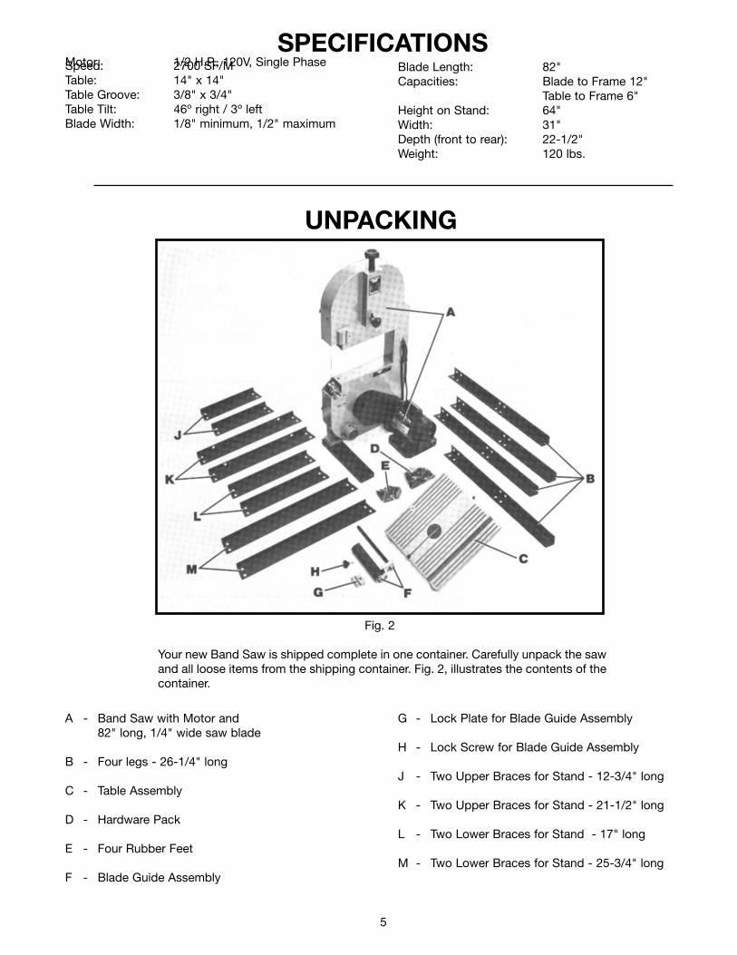
G - Lock Plate for Blade Guide Assembly
H - Lock Screw for Blade Guide Assembly
J - Two Upper Braces for Stand - 12-3/4" long
K - Two Upper Braces for Stand - 21-1/2" long
L - Two Lower Braces for Stand - 17" long
M - Two Lower Braces for Stand - 25-3/4" long
A - Band Saw with Motor and82" long, 1/4" wide saw blade
B - Four legs - 26-1/4" long
C - Table Assembly
D - Hardware Pack
E - Four Rubber Feet
F - Blade Guide Assembly
Your new Band Saw is shipped complete in one container. Carefully unpack the sawand all loose items from the shipping container. Fig. 2, illustrates the contents of thecontainer.
Fig. 2
UNPACKING
6
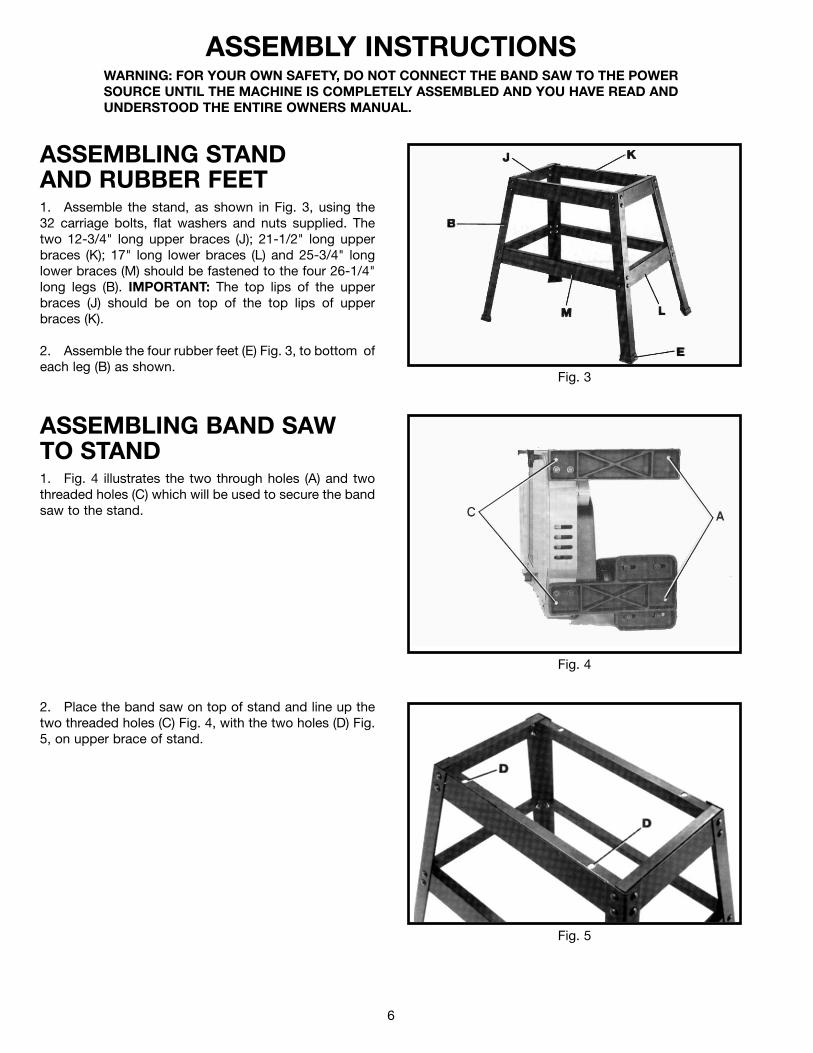
ASSEMBLING STANDAND RUBBER FEET1. Assemble the stand, as shown in Fig. 3, using the32 carriage bolts, flat washers and nuts supplied. Thetwo 12-3/4" long upper braces (J); 21-1/2" long upperbraces (K); 17" long lower braces (L) and 25-3/4" longlower braces (M) should be fastened to the four 26-1/4"long legs (B). IMPORTANT: The top lips of the upperbraces (J) should be on top of the top lips of upperbraces (K).
2. Assemble the four rubber feet (E) Fig. 3, to bottom ofeach leg (B) as shown.
ASSEMBLY INSTRUCTIONSWARNING: FOR YOUR OWN SAFETY, DO NOT CONNECT THE BAND SAW TO THE POWERSOURCE UNTIL THE MACHINE IS COMPLETELY ASSEMBLED AND YOU HAVE READ ANDUNDERSTOOD THE ENTIRE OWNERS MANUAL.
ASSEMBLING BAND SAWTO STAND1. Fig. 4 illustrates the two through holes (A) and twothreaded holes (C) which will be used to secure the bandsaw to the stand.
2. Place the band saw on top of stand and line up thetwo threaded holes (C) Fig. 4, with the two holes (D) Fig.5, on upper brace of stand.
Fig. 5
Fig. 4
Fig. 3
7
Fig. 6
Fig. 7
Fig. 9
Fig. 8
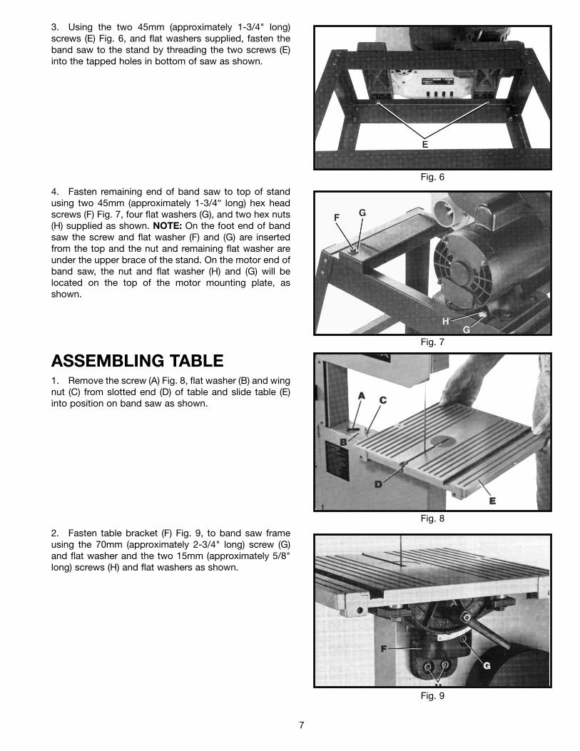
4. Fasten remaining end of band saw to top of standusing two 45mm (approximately 1-3/4″ long) hex headscrews (F) Fig. 7, four flat washers (G), and two hex nuts(H) supplied as shown. NOTE: On the foot end of bandsaw the screw and flat washer (F) and (G) are insertedfrom the top and the nut and remaining flat washer areunder the upper brace of the stand. On the motor end ofband saw, the nut and flat washer (H) and (G) will belocated on the top of the motor mounting plate, asshown.
3. Using the two 45mm (approximately 1-3/4" long)screws (E) Fig. 6, and flat washers supplied, fasten theband saw to the stand by threading the two screws (E)into the tapped holes in bottom of saw as shown.
ASSEMBLING TABLE1. Remove the screw (A) Fig. 8, flat washer (B) and wingnut (C) from slotted end (D) of table and slide table (E)into position on band saw as shown.
2. Fasten table bracket (F) Fig. 9, to band saw frameusing the 70mm (approximately 2-3/4" long) screw (G)and flat washer and the two 15mm (approximately 5/8"long) screws (H) and flat washers as shown.
8
Fig. 11
Fig. 10
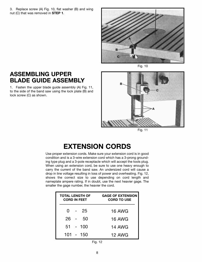
3. Replace screw (A) Fig. 10, flat washer (B) and wingnut (C) that was removed in STEP 1.
ASSEMBLING UPPERBLADE GUIDE ASSEMBLY1. Fasten the upper blade guide assembly (A) Fig. 11,to the side of the band saw using the lock plate (B) andlock screw (C) as shown.
Fig. 12
TOTAL LENGTH OFCORD IN FEET
GAGE OF EXTENSIONCORD TO USE
16 AWG
16 AWG
14 AWG
12 AWG
0 - 25
26 - 50
51 - 100
101 - 150
EXTENSION CORDSUse proper extension cords. Make sure your extension cord is in goodcondition and is a 3-wire extension cord which has a 3-prong ground-ing type plug and a 3-pole receptacle which will accept the tools plug.When using an extension cord, be sure to use one heavy enough tocarry the current of the band saw. An undersized cord will cause adrop in line voltage resulting in loss of power and overheating. Fig. 12,shows the correct size to use depending on cord length andnameplate ampere rating. If in doubt, use the next heavier gage. Thesmaller the gage number, the heavier the cord.
9
CONNECTING BAND SAW TO POWER SOURCE
POWER CONNECTIONSA separate electrical circuit should be used for your tools. This circuit should not be less than #12wire and should be protected with a 20 Amp fuse. Have a certified electrician replace or repair aworn cord immediately. Before connecting the motor to a power line, make sure the switch is inthe “OFF” position and be sure that the electric current is of the same characteristics as stampedon the motor nameplate. Running on low voltage will damage the motor.
WARNING: DO NOT EXPOSE THE TOOL TO RAIN OR OPERATE THE TOOL IN DAMP LO-CATIONS.
In the event of a malfunction or breakdown, groundingprovides a path of least resistance for electric current toreduce the risk of electric shock. This tool is equippedwith an electric cord having an equipment-groundingconductor and a grounding plug. The plug must beplugged into a matching outlet that is properly installedand grounded in accordance with all local codes andordinances.
Do not modify the plug provided - if it will not fit theoutlet, have the proper outlet installed by a qualifiedelectrician.
Improper connection of the equipment-grounding con-ductor can result in risk of electric shock. The conductorwith insulation having an outer surface that is green withor without yellow stripes is the equipment-groundingconductor. If repair or replacement of the electric cord orplug is necessary, do not connect the equipmentgrounding conductor to a live terminal.
Check with a qualified electrician or service personnel ifthe grounding instructions are not completelyunderstood, or if in doubt as to whether the tool isproperly grounded.
GROUNDING INSTRUCTIONSCAUTION: THIS TOOL MUST BE GROUNDED WHILE IN USETO PROTECT THE OPERATOR FROM ELECTRIC SHOCK.
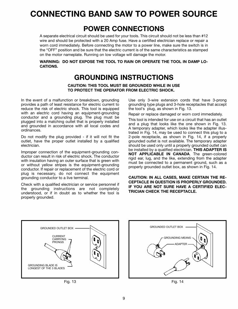
Use only 3-wire extension cords that have 3-pronggrounding type plugs and 3-hole receptacles that acceptthe tool's plug, as shown in Fig. 13.Repair or replace damaged or worn cord immediately.This tool is intended for use on a circuit that has an outletand a plug that looks like the one shown in Fig. 13.A temporary adapter, which looks like the adapter illus-trated in Fig. 14, may be used to connect this plug to a2-pole receptacle, as shown in Fig. 14, if a properlygrounded outlet is not available. The temporary adaptershould be used only until a properly grounded outlet canbe installed by a qualified electrician. THIS ADAPTER ISNOT APPLICABLE IN CANADA. The green-coloredrigid ear, lug, and the like, extending from the adaptermust be connected to a permanent ground, such as aproperly grounded outlet box, as shown in Fig. 14.
CAUTION: IN ALL CASES, MAKE CERTAIN THE RE-CEPTACLE IN QUESTION IS PROPERLY GROUNDED.IF YOU ARE NOT SURE HAVE A CERTIFIED ELEC-TRICIAN CHECK THE RECEPTACLE.
Fig. 14Fig. 13
GROUNDED OUTLET BOX
CURRENTCARRYINGPRONGS
GROUNDING BLADE ISLONGEST OF THE 3 BLADES
GROUNDED OUTLET BOX
GROUNDING MEANS
ADAPTER
10
Fig. 17
Fig. 16
Fig. 15
OPERATING CONTROLS AND ADJUSTMENTS
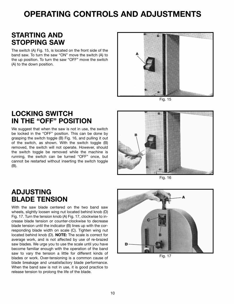
STARTING ANDSTOPPING SAWThe switch (A) Fig. 15, is located on the front side of theband saw. To turn the saw “ON” move the switch (A) tothe up position. To turn the saw “OFF” move the switch(A) to the down position.
LOCKING SWITCHIN THE “OFF” POSITIONWe suggest that when the saw is not in use, the switchbe locked in the “OFF” position. This can be done bygrasping the switch toggle (B) Fig. 16, and pulling it outof the switch, as shown. With the switch toggle (B)removed, the switch will not operate. However, shouldthe switch toggle be removed while the machine isrunning, the switch can be turned “OFF” once, butcannot be restarted without inserting the switch toggle(B).
ADJUSTINGBLADE TENSIONWith the saw blade centered on the two band sawwheels, slightly loosen wing nut located behind knob (D)Fig. 17. Turn the tension knob (A) Fig. 17, clockwise to in-crease blade tension or counter-clockwise to decreaseblade tension until the indicator (B) lines up with the cor-responding blade width on scale (C). Tighten wing nutlocated behind knob (D). NOTE: The scale is correct foraverage work, and is not affected by use of re-brazedsaw blades. We urge you to use the scale until you havebecome familiar enough with the operation of the bandsaw to vary the tension a little for different kinds ofblades or work. Over-tensioning is a common cause ofblade breakage and unsatisfactory blade performance.When the band saw is not in use, it is good practice torelease tension to prolong the life of the blade.
11
Fig. 20
Fig. 19
Fig. 18
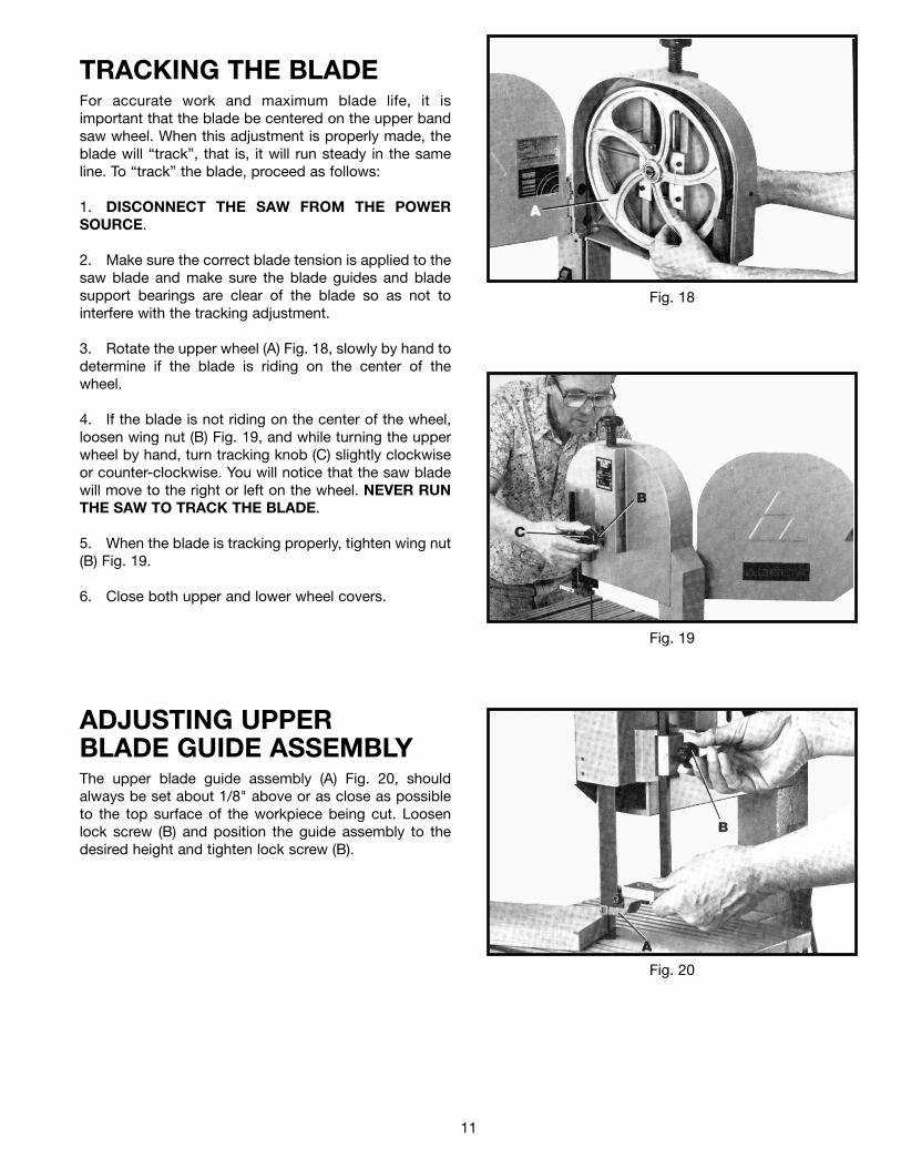
ADJUSTING UPPERBLADE GUIDE ASSEMBLYThe upper blade guide assembly (A) Fig. 20, shouldalways be set about 1/8" above or as close as possibleto the top surface of the workpiece being cut. Loosenlock screw (B) and position the guide assembly to thedesired height and tighten lock screw (B).
TRACKING THE BLADEFor accurate work and maximum blade life, it isimportant that the blade be centered on the upper bandsaw wheel. When this adjustment is properly made, theblade will “track”, that is, it will run steady in the sameline. To “track” the blade, proceed as follows:
1. DISCONNECT THE SAW FROM THE POWERSOURCE.
2. Make sure the correct blade tension is applied to thesaw blade and make sure the blade guides and bladesupport bearings are clear of the blade so as not tointerfere with the tracking adjustment.
3. Rotate the upper wheel (A) Fig. 18, slowly by hand todetermine if the blade is riding on the center of thewheel.
4. If the blade is not riding on the center of the wheel,loosen wing nut (B) Fig. 19, and while turning the upperwheel by hand, turn tracking knob (C) slightly clockwiseor counter-clockwise. You will notice that the saw bladewill move to the right or left on the wheel. NEVER RUNTHE SAW TO TRACK THE BLADE.
5. When the blade is tracking properly, tighten wing nut(B) Fig. 19.
6. Close both upper and lower wheel covers.
12
ADJUSTING UPPER BLADE GUIDESAND BLADE SUPPORT BEARING
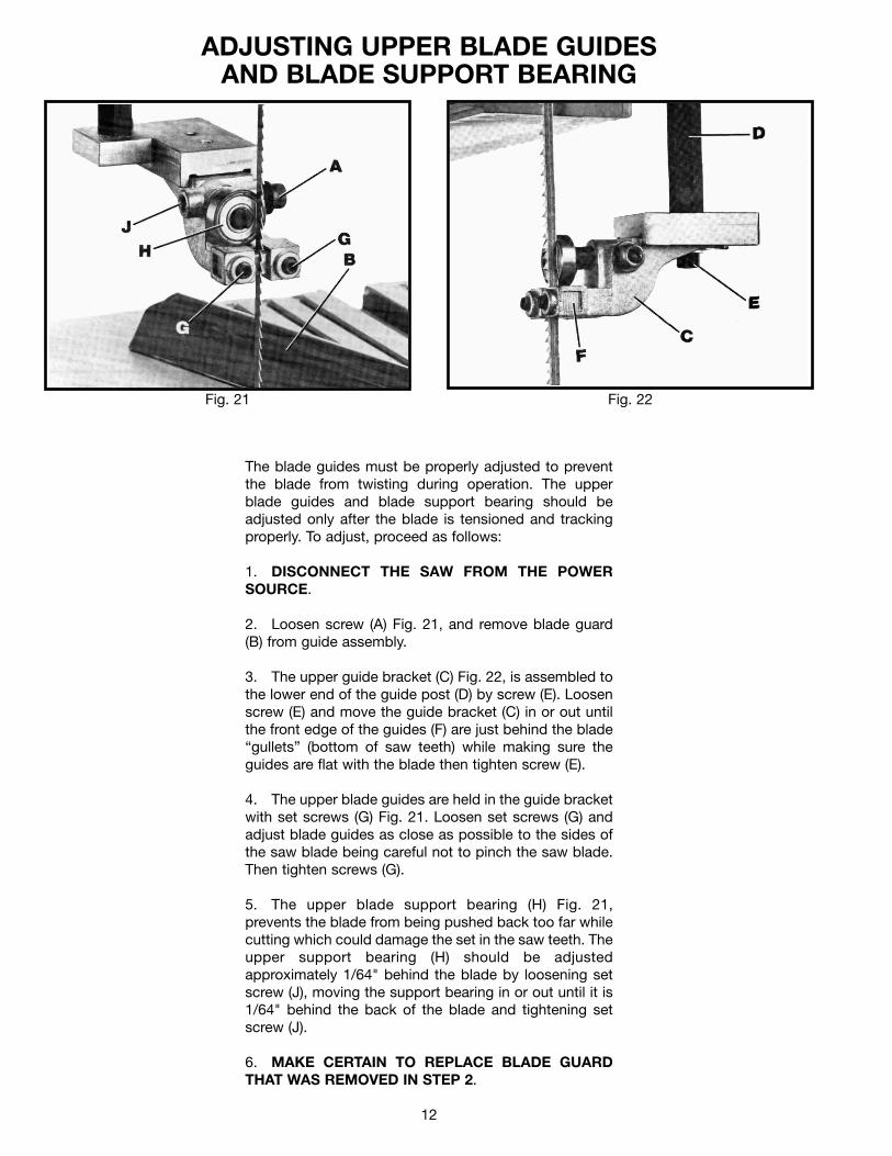
The blade guides must be properly adjusted to preventthe blade from twisting during operation. The upperblade guides and blade support bearing should beadjusted only after the blade is tensioned and trackingproperly. To adjust, proceed as follows:
1. DISCONNECT THE SAW FROM THE POWERSOURCE.
2. Loosen screw (A) Fig. 21, and remove blade guard(B) from guide assembly.
3. The upper guide bracket (C) Fig. 22, is assembled tothe lower end of the guide post (D) by screw (E). Loosenscrew (E) and move the guide bracket (C) in or out untilthe front edge of the guides (F) are just behind the blade“gullets” (bottom of saw teeth) while making sure theguides are flat with the blade then tighten screw (E).
4. The upper blade guides are held in the guide bracketwith set screws (G) Fig. 21. Loosen set screws (G) andadjust blade guides as close as possible to the sides ofthe saw blade being careful not to pinch the saw blade.Then tighten screws (G).
5. The upper blade support bearing (H) Fig. 21,prevents the blade from being pushed back too far whilecutting which could damage the set in the saw teeth. Theupper support bearing (H) should be adjustedapproximately 1/64" behind the blade by loosening setscrew (J), moving the support bearing in or out until it is1/64" behind the back of the blade and tightening setscrew (J).
6. MAKE CERTAIN TO REPLACE BLADE GUARDTHAT WAS REMOVED IN STEP 2.
Fig. 22Fig. 21
13
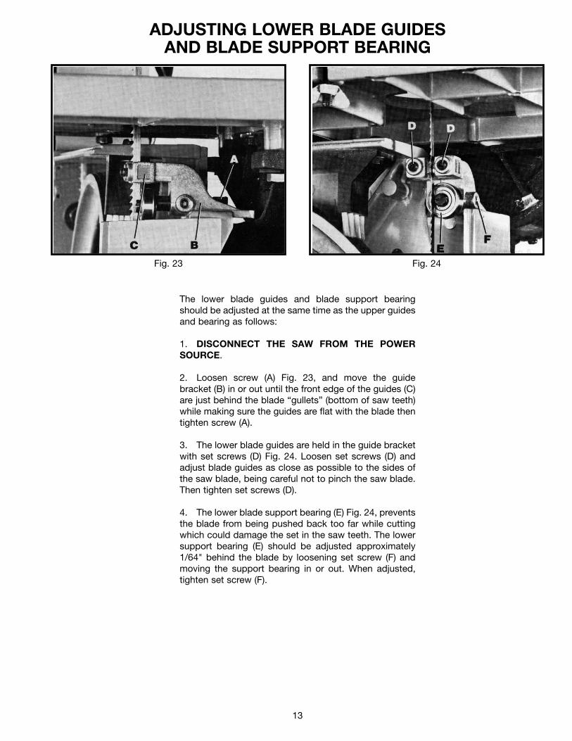
ADJUSTING LOWER BLADE GUIDESAND BLADE SUPPORT BEARING
Fig. 23 Fig. 24
The lower blade guides and blade support bearingshould be adjusted at the same time as the upper guidesand bearing as follows:
1. DISCONNECT THE SAW FROM THE POWERSOURCE.
2. Loosen screw (A) Fig. 23, and move the guidebracket (B) in or out until the front edge of the guides (C)are just behind the blade “gullets” (bottom of saw teeth)while making sure the guides are flat with the blade thentighten screw (A).
3. The lower blade guides are held in the guide bracketwith set screws (D) Fig. 24. Loosen set screws (D) andadjust blade guides as close as possible to the sides ofthe saw blade, being careful not to pinch the saw blade.Then tighten set screws (D).
4. The lower blade support bearing (E) Fig. 24, preventsthe blade from being pushed back too far while cuttingwhich could damage the set in the saw teeth. The lowersupport bearing (E) should be adjusted approximately 1/64" behind the blade by loosening set screw (F) andmoving the support bearing in or out. When adjusted,tighten set screw (F).
14
Fig. 26
Fig. 27
Fig. 25
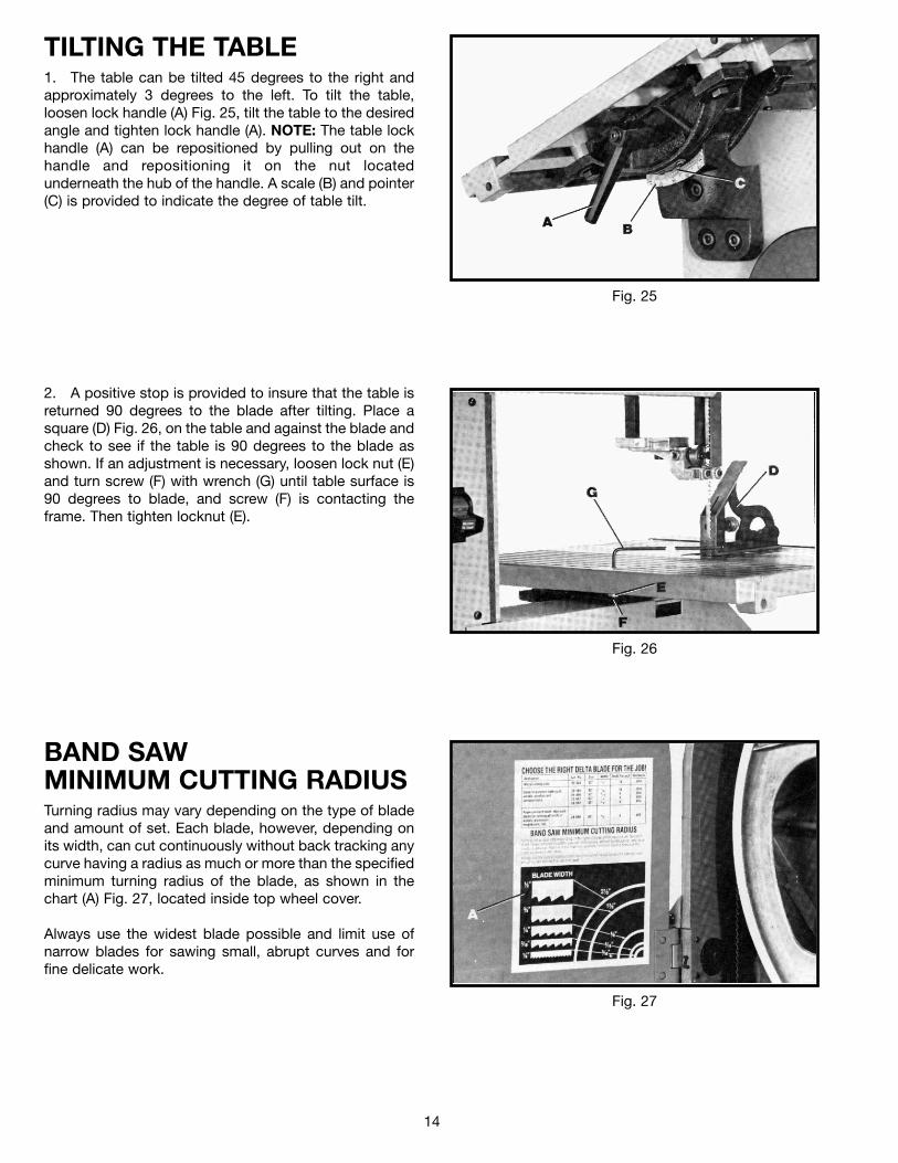
BAND SAWMINIMUM CUTTING RADIUSTurning radius may vary depending on the type of bladeand amount of set. Each blade, however, depending onits width, can cut continuously without back tracking anycurve having a radius as much or more than the specifiedminimum turning radius of the blade, as shown in thechart (A) Fig. 27, located inside top wheel cover.
Always use the widest blade possible and limit use ofnarrow blades for sawing small, abrupt curves and forfine delicate work.
TILTING THE TABLE1. The table can be tilted 45 degrees to the right andapproximately 3 degrees to the left. To tilt the table,loosen lock handle (A) Fig. 25, tilt the table to the desiredangle and tighten lock handle (A). NOTE: The table lockhandle (A) can be repositioned by pulling out on thehandle and repositioning it on the nut locatedunderneath the hub of the handle. A scale (B) and pointer(C) is provided to indicate the degree of table tilt.
2. A positive stop is provided to insure that the table isreturned 90 degrees to the blade after tilting. Place asquare (D) Fig. 26, on the table and against the blade andcheck to see if the table is 90 degrees to the blade asshown. If an adjustment is necessary, loosen lock nut (E)and turn screw (F) with wrench (G) until table surface is90 degrees to blade, and screw (F) is contacting theframe. Then tighten locknut (E).
15
Fig. 28
Fig. 29
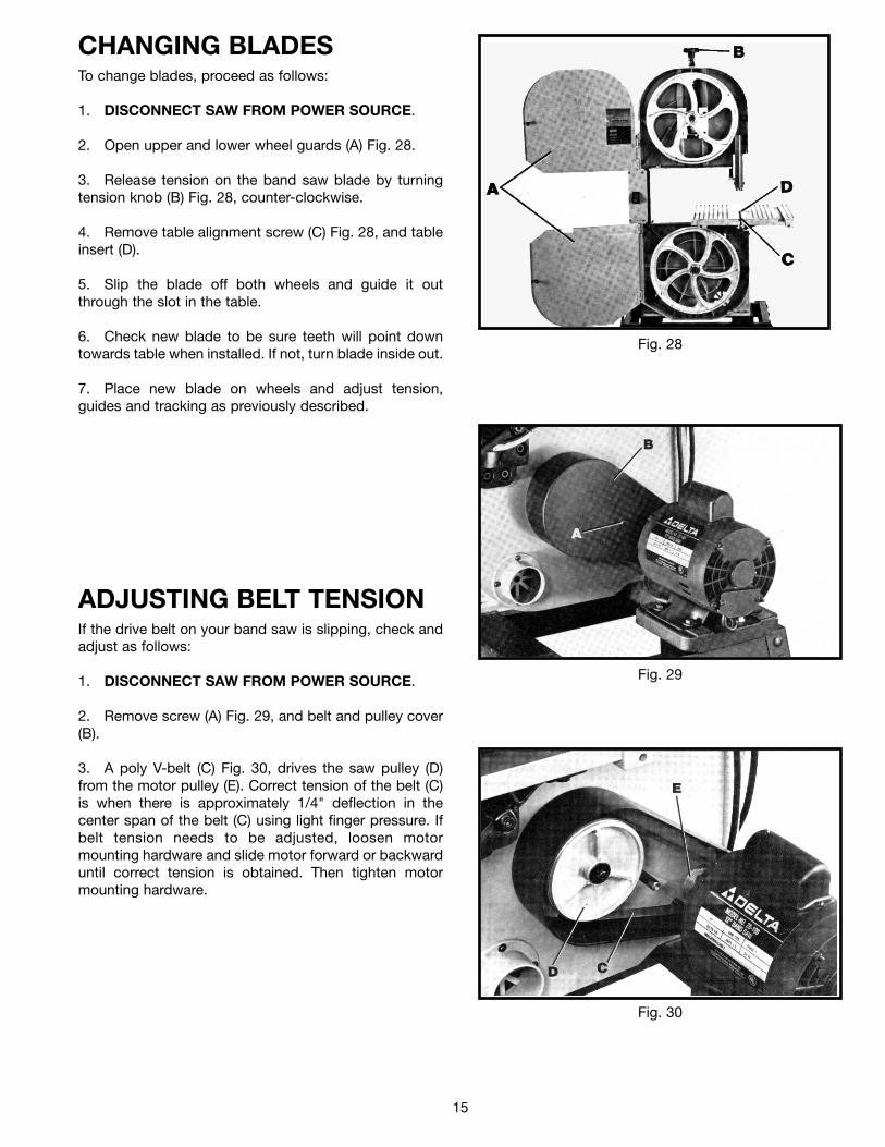
CHANGING BLADESTo change blades, proceed as follows:
1. DISCONNECT SAW FROM POWER SOURCE.
2. Open upper and lower wheel guards (A) Fig. 28.
3. Release tension on the band saw blade by turningtension knob (B) Fig. 28, counter-clockwise.
4. Remove table alignment screw (C) Fig. 28, and tableinsert (D).
5. Slip the blade off both wheels and guide it outthrough the slot in the table.
6. Check new blade to be sure teeth will point downtowards table when installed. If not, turn blade inside out.
7. Place new blade on wheels and adjust tension,guides and tracking as previously described.
ADJUSTING BELT TENSIONIf the drive belt on your band saw is slipping, check andadjust as follows:
1. DISCONNECT SAW FROM POWER SOURCE.
2. Remove screw (A) Fig. 29, and belt and pulley cover(B).
3. A poly V-belt (C) Fig. 30, drives the saw pulley (D)from the motor pulley (E). Correct tension of the belt (C)is when there is approximately 1/4" deflection in thecenter span of the belt (C) using light finger pressure. Ifbelt tension needs to be adjusted, loosen motormounting hardware and slide motor forward or backwarduntil correct tension is obtained. Then tighten motormounting hardware.
Fig. 30
16
Fig. 31
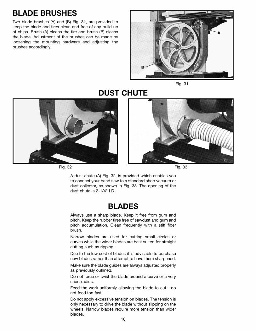
BLADE BRUSHESTwo blade brushes (A) and (B) Fig. 31, are provided tokeep the blade and tires clean and free of any build-upof chips. Brush (A) cleans the tire and brush (B) cleansthe blade. Adjustment of the brushes can be made byloosening the mounting hardware and adjusting thebrushes accordingly.
DUST CHUTE
Fig. 33Fig. 32
A dust chute (A) Fig. 32, is provided which enables youto connect your band saw to a standard shop vacuum ordust collector, as shown in Fig. 33. The opening of thedust chute is 2-1/4" I.D.
BLADESAlways use a sharp blade. Keep it free from gum andpitch. Keep the rubber tires free of sawdust and gum andpitch accumulation. Clean frequently with a stiff fiberbrush.
Narrow blades are used for cutting small circles orcurves while the wider blades are best suited for straightcutting such as ripping.
Due to the low cost of blades it is advisable to purchasenew blades rather than attempt to have them sharpened.
Make sure the blade guides are always adjusted properlyas previously outlined.
Do not force or twist the blade around a curve or a veryshort radius.
Feed the work uniformly allowing the blade to cut - donot feed too fast.
Do not apply excessive tension on blades. The tension isonly necessary to drive the blade without slipping on thewheels. Narrow blades require more tension than widerblades.

17

18
Delta Building Trades and Home Shop MachineryTwo Year Limited Warranty
Delta will repair or replace, at its expense and at its option, any Delta machine,machine part, or machine accessory which in normal use has proven to bedefective in workmanship or material, provided that the customer returns theproduct prepaid to a Delta factory service center or authorized service station withproof of purchase of the product within two years and provides Delta withreasonable opportunity to verify the alleged defect by inspection. Delta may requirethat electric motors be returned prepaid to a motor manufacturer’s authorizedstation for inspection and repair or replacement. Delta will not be responsible forany asserted defect which has resulted from normal wear, misuse, abuse or repairor alteration made or specifically authorized by anyone other than an authorizedDelta service facility or representative. Under no circumstances will Delta be liablefor incidental or consequential damages resulting from defective products. Thiswarranty is Delta’s sole warranty and sets forth the customer’s exclusive remedy,with respect to defective products; all other warranties, express or implied,whether of merchantability, fitness for purpose, or otherwise, are expresslydisclaimed by Delta.
Printed in U.S.A.