12 April, 2017 - Air Glas Install Part 1-3.pdf · EQUIPMENT AND MATERIALS 1 AIRGLAS, INC ANCHORAGE,...
19
AIRGLAS INSTALLATION, MAINTENANCE, SERVICE INSTRUCTIONS & ILLUSTRATED PARTS LIST (IMSIIPL) MANUAL MODEL L20500A SKI KIT CODE IDENT NO. 17564 THIS MANUAL INCLUDES INFORMATION PROPRIETARY TO AIRGLAS, INC. AND SHALL NOT BE USED TO MANUFACTURE OR REPRODUCE WITHOUT PERMISSION OF AIRGLAS, INC. AIRGLAS, INC ANCHORAGE, ALASKA 99507 12 April, 2017
Transcript of 12 April, 2017 - Air Glas Install Part 1-3.pdf · EQUIPMENT AND MATERIALS 1 AIRGLAS, INC ANCHORAGE,...
AIRGLAS INSTALLATION,
MAINTENANCE, SERVICE
INSTRUCTIONS & ILLUSTRATED PARTS
LIST (IMSIIPL) MANUAL
MODEL L20500A SKI KIT
CODE IDENT NO. 17564
THIS MANUAL INCLUDES INFORMATION PROPRIETARY TO AIRGLAS, INC. AND SHALL
NOT BE USED TO MANUFACTURE OR REPRODUCE WITHOUT PERMISSION OF
AIRGLAS, INC.
AIRGLAS, INC
ANCHORAGE, ALASKA 99507
12 April, 2017

TABLE OF CONTENTS
AIRGLAS, INC
ANCHORAGE, ALASKA 99507
Equipment & Materials 1
Section 1.0 Ski - Preparation Main Landing Gear 2
Section 2.0 Ski - Preparation Tail Landing Gear 2
Section 3.0 Helicopter - Preparation Main Landing Gear 2
Section 4.0 Helicopter - Preparation Tail Landing Gear 3
Section 5.0 Tail Ski - Installation 3
Section 6.0 Main Ski - Installation 4
Figure 1.0 Main Ski – Ski Preparation for Assembling to AH-64D 5
Figure 1.1 Main Ski – Ski Preparation for Assembling to AH-64D 6
Figure 2.0 Tail Ski – Ski Preparation for Assembling to AH-64D 7
Figure 3.0 Main Gear – Boeing Step and Plate Removal 8
Figure 3.1 Main Gear – Airglas Bracket and Step Assembly 9
Figure 3.2 Main Gear – Jack Pad Removal / Axle Assembly 10
Figure 5.0 Main Gear / Tail Gear – Pre-Install Ski Position 11
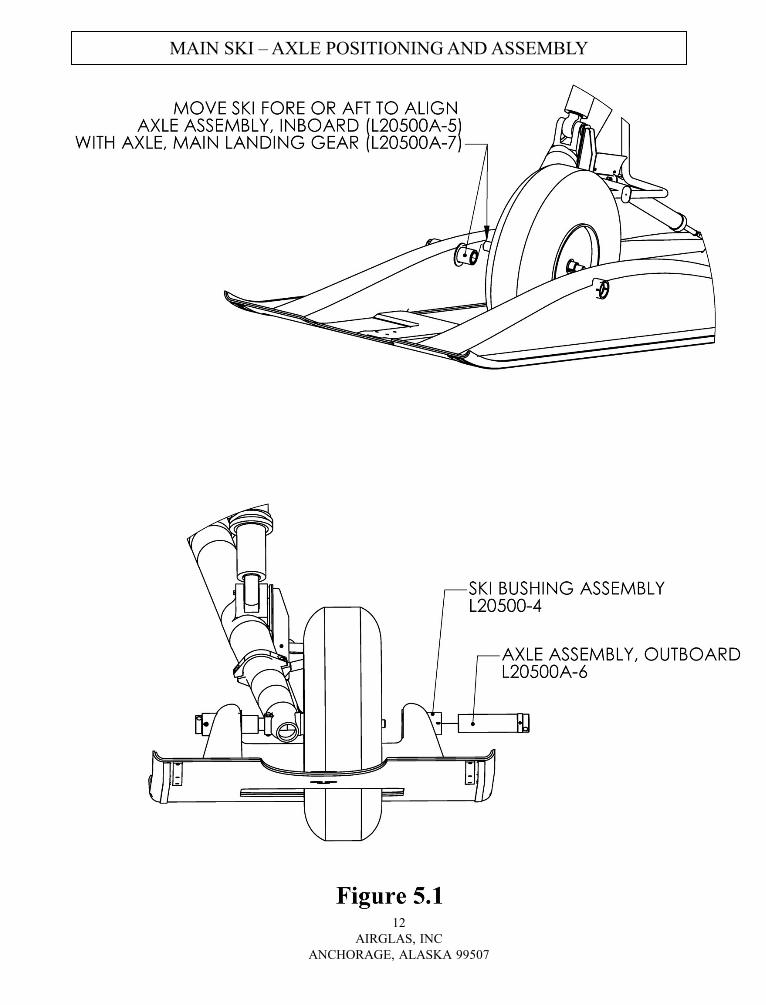
Figure 5.1 Main Ski – Axle Positioning and Assembly 12
Figure 5.2 Main Ski – Axle Positioning and Assembly 13
Figure 5.3 Main Ski – Spring Cylinder Positioning and Assembly 14
Figure 5.4 Main Ski – Check Cable Assembly 15
Figure 5.5 Main Ski – Safety Cable Assembly 16
Figure 5.6 Main Ski Check Cable Installation 17
Figure 6.0 Tail Ski – Axle Location and Assembly 18
Figure 6.1 Tail Ski – Axle Location and Assembly 19
Figure 6.2 Tail Ski – Spring Cylinder Positioning and Assembly 20
Figure 6.3 Tail Ski – Safety Cable Assembly 21
Section 7.0 Maintenance and Ground Handling Restrictions 22
Section 8.0 Maintenance Operational Checks 22
Section 9.0 Inspection Criteria 22
Section 10.0 Maintenance Tasks 23
Section 11.0 Ski Removal 30

EQUIPMENT AND MATERIALS
1
AIRGLAS, INC
ANCHORAGE, ALASKA 99507
INITIAL SETUP
PERSONNEL REQUIRED
•One: AH-64 Helicopter Repairer
•One: Aircraft Structural Repairer
•Three: Assistants
MATERIALS/PARTS
•Corrosion Preventative Compound, MIL-C-16173D,
Grade 2
•Dry Cleaning Solvent, MIL PRF-680 Type II
•SuperLube Synthetic Grease (PTFE)
•Readily Available Anti-Seize agent
•Rag, Clean, DDD-T-541
TOOLS
Aircraft Mechanic’s Tool Kit
Torque Wrench, 0 – 600 in. lbs,
GGG-W-686
Airglas Inc. does not always annotate torque values for components. When it is not identified in our manual
we recommend use of the below table to determine proper torque values. This data is from T.O. 1-1A-8 and
TM-1-1500-204-23-6. If you have any questions, please make contact us at Airglas.
GENERAL TORQUE VALUES FOR UNSPECIFIED COMPONENTS
LANDING GEAR SKIS - INSTALL MAIN AND TAIL
Section 1.0
Preparation of both skis is the same except where noted.
Right side is shown.
1. Remove and save hardware (AN3-27A bolt,
AN960-10 Washer, and AN365-1032 Nut)
holding the Axle Assy., Outboard (L20500A-6)
in place. See figure 1.0
2. Slide Axle Assy., Outboard out of fitting in ski.
See figure 1.0
3. Remove Shipping Tube covering the Axle, Main
Landing Gear (L20500A-7). See figure 1.0
4. Remove the Axle (L20500A-7) See figure 1.0
5. DO NOT REMOVE AXLE ASSY., INBOARD.
See figure 1.0
6. Remove Tail Wheel Assembly and Check Cable
from rear of the Main Ski by removing Elevator
Bolts (EB616-20, EB616-21) from the bottom
of the ski See figure 1.1 Save all hardware for
future use.
Section 2.0
7. Remove Tail Wheel Bracket Kit (L20500-18)
from back of Tail Ski Assy. (L20500A-3).
Save all hardware for future use. See Figure
2.0
8. Remove Tail Ski Axle Adapter (L20500A-13).
Save all hardware for future use See Figure
2.0
2
AIRGLAS, INC
ANCHORAGE, ALASKA 99507
SKI - PREPARATION TAIL LANDING
GEAR
SKI - PREPARATION
MAIN LANDING GEAR
HELICOPTER - PREPARATION
MAIN LANDING GEAR
Section 3.0
Preparation of both skis is the same except where noted.
Right side is shown.
9. Remove Step Assembly (7-511113527-1 & -2).
Keep existing hardware for future use. See
figure 3.0.
10. Remove Wire Cutter Assembly (443-83020-2).
Keep hardware and wire cutter assy. for future
use. See figure 3.0
11. Attach Airglas Bracket Assembly (L20500A-20
R.H., L20500A-21 L.H.) to Main Landing Gear
using existing hardware See Figure 3.1
TORQUE VALUE
12. Bolt Bracket Assembly to Clamp (443-83023-1)
(both sides) using existing hardware from Step
10. See Figure 3.1
13. Re-install Step Assembly (7-511113527-1 & -2)
to Bracket Assembly (L20500A-20, L20500A-
21) using existing hardware from Step 9. See
Figure 3.1inboard
14. Remove Jack Pad (1168321-1). Keep existing
hardware. See Figure 3.2
15. Slide Axle, Main Landing Gear (L20500A-7)
into the Trailing Arm (1168320-101) axle
housing. See Figure 3.2
16. Line up clearance hole on Axle (L20500A-7)
with clearance hole on Trailing Arm (1168320-
101).
17. Re-install existing hardware from Step 14 to
hold Axle (L20500A-7) in place. See Figure 3.2
TORQUE VALUE
18. Remove both inboard pylons.
19. Remove inboard attach bolts
20. Install check cable attach bracket PN L20500A-
11-3, see fig. 5..6
21. Match torque of existing pylon bolts.
22. Set levelers to make full contact with side of
pylon. Tighten NAS509-3C and safety the two
nuts.

REMOVE
REMOVE HARDWARE CIRCLED IN PICTURE. NOTE: ONE OF THE FASTENERS IS HIDDEN BEHIND THE STEP, ONE (UPPER
STEP BOLT) IS NOT IN PICTURE.
NOTE: RETAIN ALL HARDWARE FOR LATER USE.
REMOVAL OF STEP AND WIRE CUTTER
HIDDEN BEHIND STEP
UPPER STEP BOLT NOT SHOWN

INSTALL BOLTS REMOVED FROM WIRE CUTTER AND
STEP. USE NEW AIRGLAS PROVIDED HARDWARE AS
NEEDED.
INSTALLATION OF AIRGLAS ADAPTER ASSEMBLY
(L20500A-20 RH SIDE. L20500A-21 LH Side)
SEE FIG 3.1 FOR SPECIFIC DETAILS ON HARDWARE AND
TORQUE REQUIREMENTS
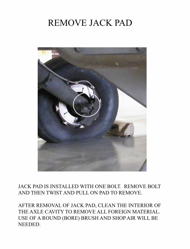
REMOVE JACK PAD
JACK PAD IS INSTALLED WITH ONE BOLT. REMOVE BOLT
AND THEN TWIST AND PULL ON PAD TO REMOVE.
AFTER REMOVAL OF JACK PAD, CLEAN THE INTERIOR OF
THE AXLE CAVITY TO REMOVE ALL FOREIGN MATERIAL.
USE OF A ROUND (BORE) BRUSH AND SHOP AIR WILL BE
NEEDED.
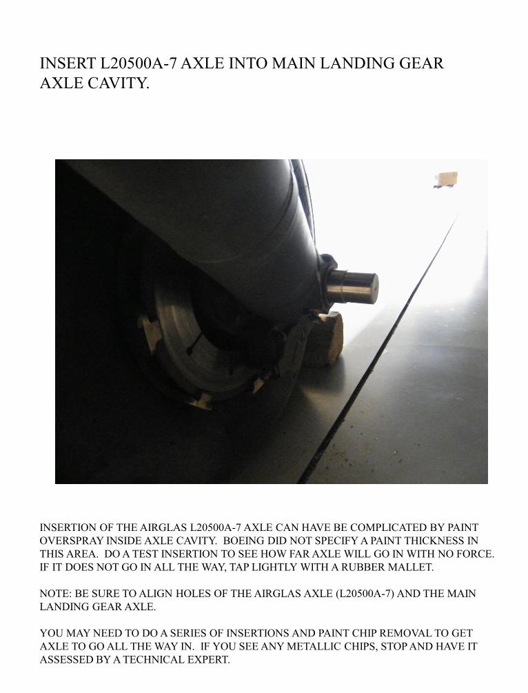
INSERT L20500A-7 AXLE INTO MAIN LANDING GEAR
AXLE CAVITY.
INSERTION OF THE AIRGLAS L20500A-7 AXLE CAN HAVE BE COMPLICATED BY PAINT
OVERSPRAY INSIDE AXLE CAVITY. BOEING DID NOT SPECIFY A PAINT THICKNESS IN
THIS AREA. DO A TEST INSERTION TO SEE HOW FAR AXLE WILL GO IN WITH NO FORCE.
IF IT DOES NOT GO IN ALL THE WAY, TAP LIGHTLY WITH A RUBBER MALLET.
NOTE: BE SURE TO ALIGN HOLES OF THE AIRGLAS AXLE (L20500A-7) AND THE MAIN
LANDING GEAR AXLE.
YOU MAY NEED TO DO A SERIES OF INSERTIONS AND PAINT CHIP REMOVAL TO GET
AXLE TO GO ALL THE WAY IN. IF YOU SEE ANY METALLIC CHIPS, STOP AND HAVE IT
ASSESSED BY A TECHNICAL EXPERT.

TAIL SKI - INSTALLATION
Section 5.0
24. Remove Bolts (AN4-7A), Washers (AN960-
416), and Nuts (A365-428), (and NAS70C-4
Washers) holding tail ski, Tail Wheel Bracket
Kit (L20500-18) to ski and remove Tail Wheel
Bracket Kit. See Figure 2.0 (retain hardware)
Note: Remove the L20500A-14-2 bracket (Item 38 of
IPB on Page 28) prior to towing helicopter onto tail
ski. This bracket will create interference with tow
bar. This is done by removing the two AN5-12A
bolts and one AN3-21A bolt (Item 8 & 41on page 28)
attaching bracket to the L20500A-14 (Item 22 on
page 28)
25. Center Tail Ski in front of Tail Gear Wheel.
See Figure 5.0
26.. Tow helicopter, or push helicopter forward,
with help of assistants, until Tail Wheel is
centered in Ski Wheel Well.
27. Lift rear ski so the Tail Ski Attach Brackets
(L20500A-14) line up with the Tail Wheel
Axle (1168819-1). See Figure 6.0
Note: Re-install the L20500A-14-2 bracket (Item 38
of IPB on Page 28) attaching bracket to the
L20500A-14 (Item 22 on page 28) This is done by
installing the two AN5-12A bolts and one AN3-21A
bolt (Item 8 & 41on page 28) removed in Step 24
above. Torque AN5-12A to 100-140 IN LBS, the
AN3-21A to 20-25 IN LBS.
28. Insert Tail Ski Axle Adapter(s) (L20500A-13)
through Ski Attach Bracket(s), place Axle Spacer(s)
(L20500A-16) on Tail Ski Axle Adapter(s). See
Figure 6.0
29. Push Ski Axle Adapter (s) into Tail Ski Axle until
clearance holes line up on Ski Attach Bracket(s) and
Ski Axle Adapter (s). See Figure 6.1
30. Insert Bolt(s) (AN3-14A) through clearance holes,
affix Washer(s) (AN960-10) and Nut(s) (AN365-
1032). See Figure 6.1 TORQUE VALUE
31. Attach Spring Cylinder, Tail Ski (L20500A-15) to
Tail Ski, Lower Attach Fitting (L20500A-19) with
Bolt (AN26-21), Washer (AN960-616L) and Nut
(AN320-6). Secure Nut with Cotter Pin (MS24665-
302). See Figure 6.2 TORQUE VALUE
32. Insert Bushings (L20500A-22) into 3/8 hole in
Eye Bolt, SPL (L20500A-23) one from each
side. See Figure 6.2
33. Hold the Spring Cylinder in one hand, lift the
front of the ski, and position the upper Eye
Bolt (L20500A-23) so that the Eye Bolt is
lined up with the Bushings and tlg wheel fork
assy lugs 1168850. Insert Eye Bolt
(L20500A-24) Affix Washer (AN960-416)
and Nut (AN310-4). Instl MS24665-151
cotter pin. See Figure 6.2
34. Install Safety Cable Tail Ski (L20500A-17)
onto Tail Ski using Washer (30185), Screw
(NAS514P524-16), Washer (AN960-516) and
Nut (AN365-524). See Figure 6.3 TORQUE
VALUE
35. Attach upper portion of Safety Cable to Eye
Bolt (L20500A-24) using Clevis Pin (AN394-
15) and Cotter Pin (MS24665-151). See Figure
6.3
36. Re-Install Tail Wheel Bracket Kit (L20500-
18). See Figure 2.0
HELICOPTER - PREPARATION
TAIL LANDING GEAR
Section 4.0
23. Remove Wire Strike (Deflector) from Tail
Landing Gear and all associated hardware.
NOTE: The bolts that attach wire strike to tail wheel
axle will need to be replaced with NAS6405-32 bolts,
or an alternate temporary method by using a washer
stack added to replace the thickness of the wire strike
attach lugs. Washers should be replaced at the next
major maintenance inspection. These bolts are in
shear, so washer stack has no impact on joint
strength.
3
AIRGLAS, INC
ANCHORAGE, ALASKA 99507

Tail ski with L20500A-14-2 Tow Bar Adapters and
L20500-18 tail wheel assembly removed
Tail ski with L20500A-14-2 Tow Bar Adapters
reinstalled and connected to tow bar.
Tail ski with L20500A-14-2 Tow Bar Adapters
reinstalled and L20500-18 tail wheel assembly
being installed.

LANDING GEAR SKIS - INSTALL MAIN AND TAIL
4
AIRGLAS, INC
ANCHORAGE, ALASKA 99507
MAIN SKI - INSTALLATION
Section 6.0
37. Center Main Skis in front of Main Landing Gear
Wheels See Figure 5.0
38. CAUTION – To avoid damage to ski take
extreme care to ensure that the wheels are on the
outboard part of the wheel wells.
39. Install Airglas installation ramps on both main
skis.
40. Tow helicopter or push helicopter forward with
help of assistants until the main wheels are
centered in the ski wheel well.
41. Lubricate Axle, Main Landing Gear (L20500A-
7) with thin coat of Synthetic Grease (PTFE).
42. Lift tail of main ski off the ground and slide fore
or aft to align the Axle Assembly, Inboard
(L20500A-5) (which was left on the ski) with
the Axle, Main Landing Gear (L20500A-7).
Slide ski outboard until Axle (L20500A-7) is
properly seated in Inboard Axle (L20500A-5).
See Figure 5.1
43. Coat Axle Assy., Outboard (L20500A-6)
threads with anti-seize agent. Coat Axle Assy.,
Outboard (L20500A-6) body with corrosion
preventative compound , MIL-C-16173D, Grade
2.
44. Insert Axle Assy., Outboard (L20500A-6) into
Main Ski Bushing Assy. (L20500-4) and thread
Ski Axle into Ski Bushing. See Figure 5.1
45. Thread Inboard and Outboard Ski Axles until
both are evenly seated on Axle, Main Landing
Gear (L20500A-7). See Figure 5.2
46. Back off Inboard and Outboard Ski Axles until
the holes line up to slots on the Ski Bushing.
47. Install bolt(s) (AN3-27A) through Inboard and
Outboard Axles and Ski Bushing. Affix
Washer(s) (AN960-10) and Nut(s) (AN365-
1032) onto bolt(s) See Figure 5.2.TORQUE
NUTS TO 20 – 25 INCH-POUND.
48. Install Spring Cylinder, Main Ski (L20500A-8)
on forward Ski Eye Bolt (AN47-14) with Clevis
Bolt (AN396-23) and Cotter Pin (MS24665-
302) and to the Upper Mounting Bracket
(L20500A-21-3) with Clevis Bolt (AN26-25),
(2) Washers (AN960-616L) and Nut (AN320-
6), (4) Special Washers (P/N 528D378D050 (2
each side of rod end). See Figure 5.3 TORQUE
VALUE
49. Install Check Cable (L20500A-11) to check
cable bracket, PN L20500A-11-3 using Clevis
Pin and Cotter Pin.
50. Re-Install Tail Wheel Assembly (L20500-
D501A) See Figure 1.1
51. Align Check Cable to Ski Angle Bracket
(L20500A-11-1A, L20500A-11-1B), Insert
Clevis Pin (AN396-23) and Cotter pin
(MS24665-302). See Figure 5.4
52. Install lower end of Safety Cable Assy.
(L20500A-12) to ski with Bolt (AN5-6A)
Washer (AN960-516L) Nut (AN365-524). See
Figure 5.5. TORQUE VALUE Install upper end
to Eye Bolt (AN45-11) at 2nd hole back on
Bracket Assy. (P/N L20500A-20, L20500A-21)
Fasten with clevis pin (AN395-17) and secure
with cotter pin MS249665-302. See Figure 5.5.

5
AIRGLAS, INC
ANCHORAGE, ALASKA 99507
MAIN SKI – SKI PREPARATION FOR ASSEMBLING TO AH-64D

MAIN SKI – SKI PREPARATION FOR ASSEMBLING TO AH-64D
6
AIRGLAS, INC
ANCHORAGE, ALASKA 99507

7
AIRGLAS, INC
ANCHORAGE, ALASKA 99507
TAIL SKI – SKI PREPARATION FOR ASSEMBLING TO AH-64D
FIGURE 2.

8
AIRGLAS, INC
ANCHORAGE, ALASKA 99507
MAIN GEAR – BOEING STEP AND PLATE REMOVAL

9
AIRGLAS, INC
ANCHORAGE, ALASKA 99507
MAIN GEAR – AIRGLAS BRACKET AND STEP ASSEMBLY
40-50 IN-LBS
40-50
MS24665-151 COTTER PIN
TORQUE TO 40-50 IN LB

10
AIRGLAS, INC
ANCHORAGE, ALASKA 99507
MAIN GEAR – JACK PAD REMOVAL / AXLE ASSEMBLY

11
AIRGLAS, INC
ANCHORAGE, ALASKA 99507
MAIN GEAR / TAIL GEAR – PRE-INSTALL SKI POSITION
12
AIRGLAS, INC
ANCHORAGE, ALASKA 99507
MAIN SKI – AXLE POSITIONING AND ASSEMBLY