12-15 EVALUATION OF TYPICAL WELDED INTERIM …digital.lib.lehigh.edu/fritz/pdf/385_1.pdf · 12-15...
72
12-15 EVALUATION OF TYPICAL WELDED BRIDGE DETAILS FOR FATIGUE DESIGN by John W. Fisher INTERIM REPORT NCHRP PROJECT 12-15 DETECTION AND REPAIR OF FATIGUE CRACKING IN HIGHWAY BRIDGES Prepared for Highway Research Board National Cooperative Highway Research Program National Academy of Sciences Fritz Engineering Laboratory Department of Civil Engineering Lehigh University Bethlehem, Pennsylvania September 1973 Fritz Engineering Laboratory Report 385.1
Transcript of 12-15 EVALUATION OF TYPICAL WELDED INTERIM …digital.lib.lehigh.edu/fritz/pdf/385_1.pdf · 12-15...

12-15
EVALUATION OF TYPICAL WELDED
BRIDGE DETAILS FOR FATIGUE DESIGN
by John W. Fisher
INTERIM REPORT
NCHRP PROJECT 12-15 DETECTION AND REPAIR OF FATIGUE CRACKING
IN HIGHWAY BRIDGES
Prepared for Highway Research Board
National Cooperative Highway Research Program National Academy of Sciences
Fritz Engineering Laboratory Department of Civil Engineering
Lehigh University Bethlehem, Pennsylvania
September 1973
Fritz Engineering Laboratory Report 385.1

TABLE OF CONTENTS
1. INTRODUCTION
2. FATIGUE STRENGTH AND DESIGN VARIABLES
3. CLASSIFICATION OF TYPICAL BRIDGE DETAILS
CATEGORY A CATEGORY B CATEGORY C CATEGORY D CATEGORY E CATEGORY F
4. DETAILS NOST SUSCEPTIBLE TO FATIGUE
5. SIGNIFICANCE OF FABRICATION AND MANUFACTURING DISCONTINUITIES
6. REFERENCES
7. TABLES
8. FIGURES
ii
Page
1-2
3-7
8
8-9 10-11 11-12 12-13 13-15
16
17
18-29
30-31
32-36
Acknowledgement
This work was sponsored by the American Association of State High
way Officials, in cooperation with the Federal Highway Administration~
and was conducted in the National Cooperative Highway Research Program
which is administered by the Highway Research Board of the National
Academy of Sciences - National Research Council.
The study was carried out at the Fritz Engineering Laboratory,
Department of Civil Engineering, Lehigh University, Bethlehem, Penn
sylvania. Dr. S. Desai assisted with the analytical studies of the
stress concentration effect.
Disclaimer
This copy is an uncorrected draft as submitted by the research
agency. A decision concerning acceptance by the Highway Research
Board and publication in the regular NCHRP series will not be made
until a complete technical review has been made and discussed with the
researchers. The opinions and conclusions expressed or implied in
the report are those of the research agency. They are not necessarily
those of the llighway Research Board, the National Academy of Sciences,
the Federal Highway Administration, the American Association of State
Highway Officials, or of the individual states participating in the
. National Cooperative Highway Research Program.
iii

1. INTRODUCTION
Fatigue studies on rolled, welded, cover-plated, and gro~ve weided
beams and on beams with stiffeners and attachments fabricated from A36,
A441, and A514 steels have revealed that the primary variables influ-
, 't.. · · encing· the fatigue strength are the type of detail and the stress range'
to which. the detail is subjected. The work on NCHRP Project 12-7 has
lead to the development of comprehensive changes to the fatigue pro
visions of the AASHO specifications. The revisions use the concept of
stress range for each design detail and loading conditions. The use
of stress range greatly simplifies design computations and at the same
time reflects the available experimental and theoretical fatigue find
ings defining significant design variables.
The revisions to Article 1.7.3 of the AASHO specifications are
summarized in Tables 1 and 2. Table 1 gives the allowable ranges of
stress for a number of categories that are defined in Table 2. The
results are comprehensive and cover both welded and mechanically
fastened joints.
The objective of this state of art review of existing and current
ly designed welded bridge details is to identify these details in terms
of the specification provisions. The categories that are defined in
detail on Table 2 of the specification are illustrated by various types
of joints that are in common use. Bridge details that were used on
bridges in various parts of the United States were examined and class
ified according to their severity.
1
This report was prepared as part of NCHRP Project 12-15, "Detec
tion and Repair of Fatigue Cracking in Highway Bridges." It is intend
tion and Repair of Fatigue Cracking in Highway Bridges. i• It is intend
ed to provide designers and others with a better understanding of de
sign conditions and the severity of various details.
2
2. FATIGUE STRENGTH AND DESIGN VARIABLES
In the past, only approximate general design relationships have
been possible because of the limited experimental data available. Re-
search undertaken on NCHRP Project 12-7 has been reported in NCHRP
... Report 102 entitled. "Effect of. Weldments on the Fatigue Strength of
Steel Beams", 1
and the final report on NCHRP Project 12-7 (1) (NCHRP Re.-
2 port 147), entitled "Fatigue Strength of Welded Beams." These studies
on some 531 steel beams and girders having two or more details has
shown that stress range is the most significant stress factor for de-
signing a given detail against fatigue. Other stress variables and
the type of steel do not significantly affect the fatigue strength
providing the yield point is not exceeded. Since static strength pro-
visions prevent the maximum stress from exceeding 0.55 a , there are y
obvious advantages to uses of high strength steels under large dead
loads. These findings were found to be applicable to every beam and
detail examined. They included rolled beams, welded beams, groove
welded splices with the reinforcement removed at transitions in width,
square ended cover plates with and without transverse end welds, cover
plate width and thickness transitions, multiple cover plates, and
beams with stiffeners and attachments.
The cracks in the rolled beams were observed to O+iginate from
the rolled surface of the tension flange. Cracks generally initiated
from small discontinuities in the flange surface. These discontinui-
·ties were all small and resulted in a high fatigue strength condition.
The lower bound to the results of the rolled beam studies were utilized
3

to develop the design relationship for stress Category A. This pro
vides the highest stress range that the base metal or rolled element
can be subjected to for a given number of stress cycles.
In·welded built-up beams the crack causing failure_initiated at
a discontinuity in the.fillet weld at the flange-to-web junction. In
nearly all situations the crack started at discontinuities such as gas
pockets, blow holes, and other fusion type discontinuities and took
the shape of a disk perpendicular to the stress field. The fatigue
strength of the welded beam was observed to be about 75% of the
strength provided by the rolled beam. This was used to define stress
category B in Table 1.
In beams with groove welded flange splices at transition in width,
fatigue crack propagation generally occurred either from a weld dis
continuity in the longitudinal fillet weld at the flange-to-web junc
tion in a manner similar to the plain welded beams or initiated in the
ground groove weld detail near a discontinuity or mechanical notch
that was caused by the grinding operation. A relatively high fatigue
strength resulted and the test results for the flange transition at a
groove weld with the reinforcement removed provided a fatigue strength
that was identical to the welded beam. (Category B)
Fatigue crack propagation at nearly all other structural details
occurred as cracks initiated from the toe of fillet or groove welds.
In general, the growth of fatigue cracks at such locations are most
likely to occur because the area is a region of high stress concentra
tion and is also the location of the initial discontinuity and resid
ual tension stress. The initial micro-discontinuity condition is pro-
4

vided by slag inclusions, undercut, and other conditions that exist at
the toes .of both fillet and groove welds. These imperfections are
common to all welding procedures. Such flaws cannot be avoided, al
though their sizes and frequency of occurrance may be controlled by
J ,varipus w.elding techniqu~s. · The .. various details examined:., cover
plated beams, stiffeners, and other types of attachments only differ
in behavior as the stress concentration condition changes because of
the geometry of the detail and the state of residual stress. Trans
verse stiffeners w·hich provide a minimum length of detail in the di
rection of the primary bending stress provide the least decrease in
fatigue strength. In general the discontinuity results in crack
growth in the form of a semi-elliptical shape until the crack has pen
etrated the thickness of the load carrying element. Thereafter very
rapid growth occurs and relatively little life remains in the structu
ral detail.
The reduction in fatigue strength at a transverse stiffener is
approximately 50% to 55% of the strength for base metal or rolled beam
and is defined by Category C. Category C is also applicable to short
attachments up to 2 inches in length in the direction of the applied
stress.
As the attachment length is increased for either fillet or groove
welded flange attachments or longitudinal stiffeners or attachments to
the web, the forces developed in the attachment increase with an in
crease in length. This causes an increase in the stress concentration
effect \vhich in turn decreases the fatigue strength. For fillet or
5
•· : ~ .
groove welded attachments up to 4 inches in length an additional 10%
decrease in fatigue strength results. Design Category D was developed
to provide for this type of detail.
As the length of an attachment continues to increase, the fatigue
strength was observed to further decrease. The longer attachment pro
vided the same behavior as a cover plated beam when the length in the
direction of the applied stress was equal to two or three times the
width of the attachment. A reduction in fatigue strength of 60% to
70% from the rolled beam is experienced at the lower bound cover
plated beam condition. (Category E) The increasing length of the at
tachment results in the development of greater forces in the attach-
ment which in turn cause a more severe stress concentration condition
at the termination of a weld. All experimental evidence on fillet
and groove welded details verify the reduction in fatigue strength
with increasing attachment length. 3 Studies show that a cover plated
section reached conformance with the theory of flexure at a distance
from the end equal to approximately twice the cover plate width for
beams with end welds across the cover plate end and a distance equal
to approximately three times the cover plate width for beams with no
end welds. 4 Hence, the limiting decrease defined by longer attach
ments is reasonable. Finite element studies of the stress field and
stress concentration conditions confirmed the general trend of the ex-
perimental observations.
The studies have also indicated that details located in com-
pression stress regions are not fatigue critical unless there is a
possibility of some stress reversal. Although cracks may form at the
6

detail in a residual tensile stress region, these cracks will not pro
pagate beyond the tension residual region and do not adversely effect
the members load carrying capability. The crack provides a condition
analogous to any compression splice which has been proportioned to
_c~rry. pnly part of the members strength.
A fracture mechanics analysis of crack growth indicated that the
behavior of structural details which experience crack growth from the
weld toe termination are primarily dependent upon changes in the
stress concentration at the weld toe .. Hence the evaluation of other
structural details can also utilize studies of the stress concentra
tion condition to help provide an approximation of their fatigue
behavior.
7

3. CLASSIFICATION OF TYPICAL BRIDGE DETAILS
Welded. bridge details were examined and classified according to
their severity on the basis of existing experimental data and analyti-
cal studies of the stress concentration effect and initial stress in-
'"'.tensi.ty_ fac.tor .... Details are. gro.uped in accordance .with the six _cate-
gories of fatigue stresses defined in Table 1. These categories, which
range from Category A, which permits the highest allowable range of
fatigue stress, to Category E which provides the lowest allowable
ranges of stress are described in general terms in Table 2. Category
F applies to the shear stress on the throat of fillet welds and is
similar to Category E in magnitude.
:' .... - . ,A .. number of. these. bridge·,,details are shown in Figs. 1-30. In each .
figure the detail is provided with one or more classifications depend-
ing on the location and direction of the applied stress. A small
double-ended arrow is shown near or adjacent to the detail to indicate
the direction of the stress field that is affected by the stress ca-
tegory shown. The arrow indicates the critically stressed point in
the base metal adjacent to the weld.
Category A
Structural components and joints that fall under Category A are
only provided by the plain material with rolled or cleaned surfaces.
This "base metal" condition is for rolled shapes and plate without a
welded detail. It provides the upper limit to the fatigue strength
of a structural detail. Fatigue studies on A36, A441, and A514 steel
rolled beams have shown that the fatigue cracks originated from the
8
I -:

surface of the tension flange. Studies on plate specimens have also
shown that the fatigue crack originates from the surface of the plate
specimen. The point of crack initiation is a micro-discontinuity in
the flange surface. Generally these are observed to occur at locally
adhered mill scale or other similar surface imperfections. If the
surface discontinuity is at the edge of a flange or plate it is
slightly more severe. This results from the higher stress intensity
factor at an edge. The wide scatterband observed with the rolled beam
specimens reflects the variability of the initial imperfection. The
design recommendations are based on the lov1er confidence limit which
corresponds to the worst initial condition.
Small sharp surface indentations are more severe than the larger
more gradually occurring surface depressions caused by pitting from
rolled-in mill scale or roll marks. The usual slight surface depres
sions from rolled-in mill scale are not as detremental to the fatigue
strength as a sharp surface indentation. None of the test beams have
indicated the existence of sharp surface cracks at points of rolled
in mill scale or roll marks. The surface of rolled elements provides
a notch condition which isn't very severe and this results in a rela
tively high fatigue strength.
Figures 1 and 2 show typical rolled beam and plate elements which
are defined by Category A. The small arrow on the flange indicates
the direction of the limiting stress. The category is sho>vn by the
circled letter.
9
Category B
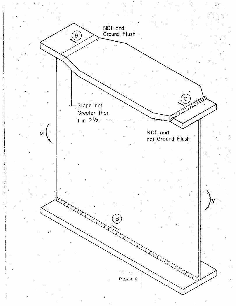
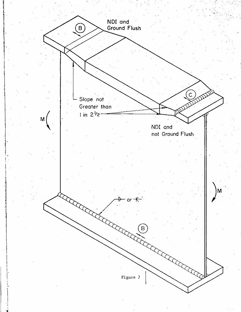
StressJCategory B applies to a variety of welded beam details.
Among the details for which this stress catesory is applicable are
groove welded joints with the reinforcement removed and the weld
soundness established by non-destructive inspection. Typical bridge
details that fall into this category are shown in Figs. 3 to 10. They
include groove welded plates of similar profiles that have been ground
flush (reinforcement removed) as illustrated in Figs. 3 and 4 for
flange and web, and straight tapered transition details which have the
reinforcement removed and a slope not greater than 1 and 2~ inches in
either the thickness or width (see Figs. 5, 6 and 7).
Groove welds at transitions in width sometimes utilize a curved
.;J:.raditis transition. (This transition is required for A514 steeL) If
the reinforcement has been removed and the weld soundness established
by non-destructive inspection, Category B is also applicable. Typi
cal examples of curved transitions at gusset plates and at flange
thickness and width transitions are shown in Figs. 8, 9, and 10.
Longitudinal welds in built-up plates or shapes that are contin
uous and parallel to the direction of the applied stress field also
fall into stress Category B. This includes the groove and fillet
welded web-to-flange connection of welded build-up girders shown in
Figures 3 to 7 and 10 to 17. As long as the longitudinal weld is con
tinuous, the primary factor influencing the fatigue strength is the
discontinuities that exist in the weldment. If crack growth occurs
it results in embedded disk-like cracks that originate in the weldment
10

at these discontinuities. Since there. is no significant stress con
centration condition, a high fatigue strength results. The same fa
tigue strength relationship is applicable to continuous groove welds
and longitudinal fillet welds.
Stress Category B is also applicable to continuous longitudinal
welds for attachment, gussets, and cover plates. Only the weld-toe
termination at the end of the longitudinal weldment has a substantial
decrease in fatigue strength. Examples of the portions of the welds
for which Category B is applicable are shown in Fig. 21, 23, and 24.
Category C
Stress Category C is primarily applicable to short attachments
and. stiffeners which exhibit fatigue crack growth from terminating
weld toes. In addition it is also applicable to groove welded connec
tions which have the reinforcement left in place and the weld sound
ness established by non-destructive inspection when the applied
stresses are perpendicular to the weld. Groove welds that are paral
lel to the applied stresses are governed by Category B and are compar
able to continuous fillet welds.
Example of various groove welded splices with the reinforcement
in place are given in Figs. 3 to 7 and in Figs. 27 to 30.
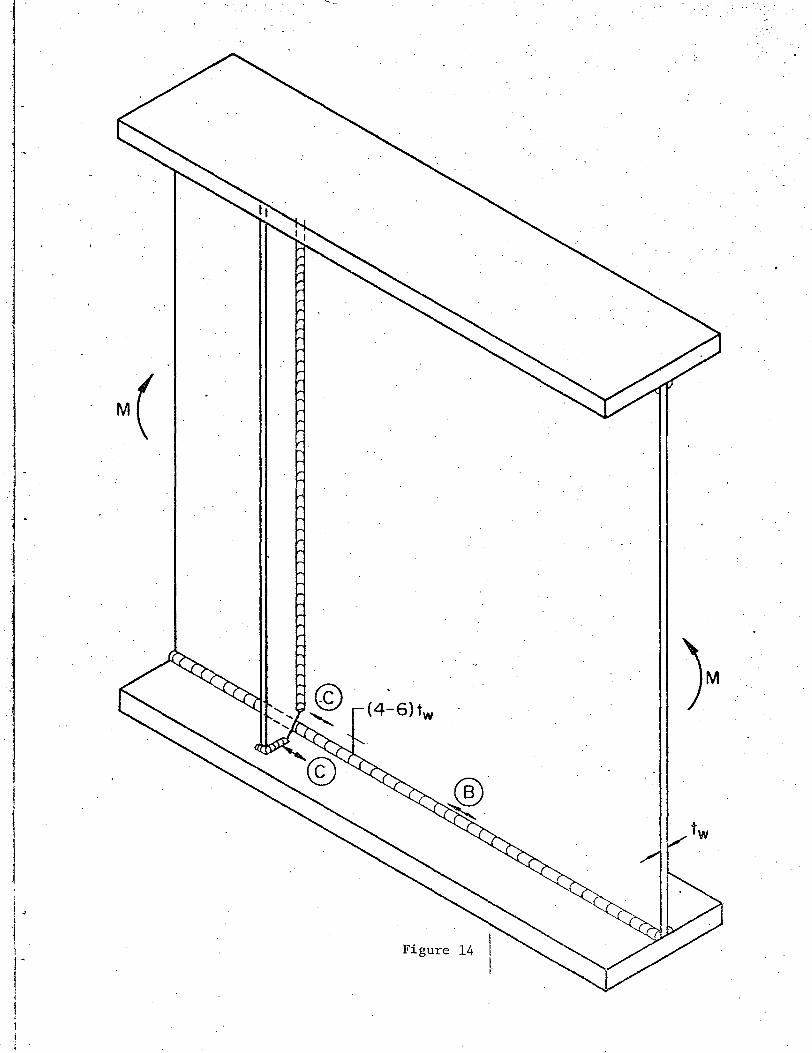
Figures 12, 13 and 14 show a number of stiffener details that
fall into Category C. Transverse stiffeners welded to the web and
transverse \velds attaching the stiffener to the flange are in the same
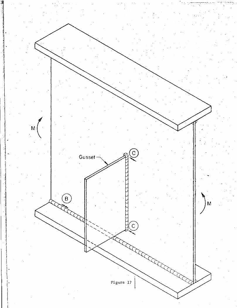
stress category. Category C is also applicable to vertical gussets
attached to the web as indicated in Fig. 17 and to other short flange
11
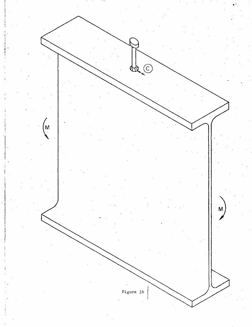
attachment less than 2 inches long. A stud shear connector in the
· "' ·.~ · ·~:s:negative motnen(t region reduce•s the·~ strength of the· flange to Category··· 1
C (see Fig. 16). In all of these cases the critical point is in the
base metal adjacent to the weld.
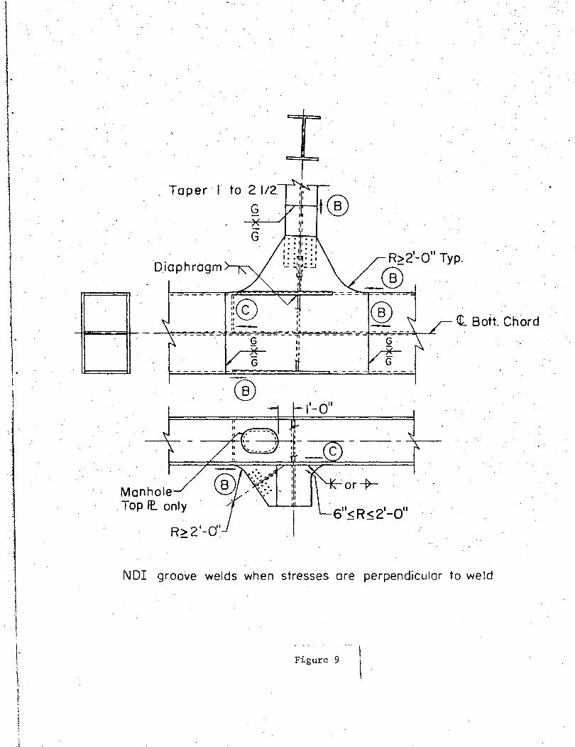
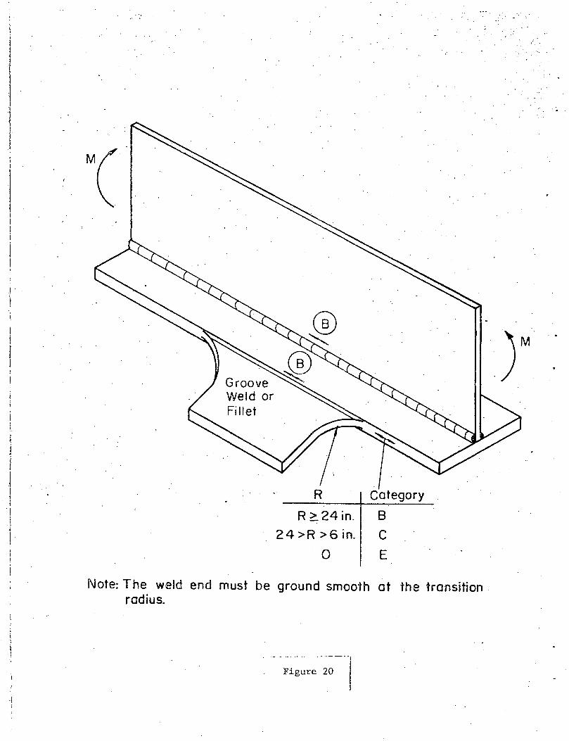
If attachments are fillet or groove welded to the edge of the
flange as indicated in Fig. 20, the stress category at the weld termi
nation is dependent upon the radius transition. If the transition ra
dius is sharp (RrvO), a fillet or groove weld provides a right angle
attachment similar to the flange attachment in Fig. 19 and stress Ca
tegory E is applicable. If the radius transition is less than 24
inches but greater than 6 inches Category C is applicable as illustra
ted in Figs. 9 and 20. The improvement in fatigue strength results
.from. a. decrease. in the stress •.. concentration condition with .. an~increase ....
in the transition radius R and the removal by grinding of the weld
ends. It is equally applicable to attachments to the web or flange.
In most bracket attachments to the web or flange, the transverse
forces acting on the bracket are in equilibrium. Hence the weld at
taching the bracket to the web or flange is primarily subjected to
shear. Hence such weldments can be treated as other longitudinal
welds.
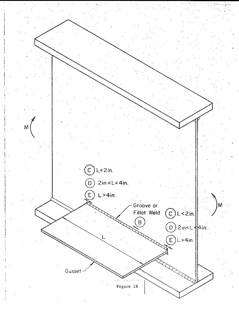
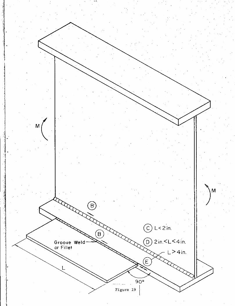
Category D
Category D provides for the transition between short fillet or
groove welded attachments and longer attachments such as cover plates.
If the attachment length in the direction of the applied stress is
greater than 2 inches but less than 4 inches, the controlling stress
12
·at the weld end is given by Category D (see Figs. 18 and 19).
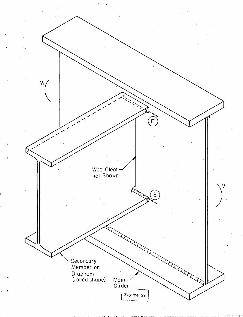
Category D is also applicable to the cross beam connection shown
in Fig. 27. The secondary rolled beam has part of the web cut away.
The change in geometry at the flange-to-web junction provides a stress
concentration effect. Analytical studies indicate that the fatigue
strength is reduced to stress Category D because of the resulting
stress concentration. An increased fatigue strength can be developed
by providing a radiused transition at the rolled beam cut-out. A one
inch radius at the web-flange juncture can increase the fatigue
strength in a rolled beam to Category B.
When cross girder connections are made by groove welding the
.. cross beam flanges to the girder flange, a decreased fatigue strength
can result as illustrated in Fig. 30. When the flanges are not of
· equal thickness the stress concentration condition reduces the fatigue
strength of the secondary girder connection to Category D or E. If
higher fatigue strength is desirable it is preferable to make the
cross girder flange continuous by passing it over the top of the gir
der ~lange (see Fig. 28) or by passing it through the web.
Other possible applications of stress Category D would be short
bar connections and flanges or channel type shear connectors which
are between 2 and 4 inches long. If these attachments are placed in
negative moment regions the reduced stress provided by Category D is
applicable.
Category E
A wide class of fillet and groove welded details are covered by
13
stress Category E. It provides the lower bound fatigue strength of
welded details and has been defined by experimental work on cover
plated beams and other comparable type connections. Studies on at
tachments have shown that when the attachment length exceeds 4 inches,
the fatigue strength rapidly approaches the lower bound cover-plated
beam condition. The critical point is at the end of the longitudinal
weld. Crack growth originates at micro-discontinuities at the weld
toe and continues perpendicular to the stress field into the plate
thickness.
A number of commonly used details have fatigue strengths that are
decreased to this lower bound condition. This includes the weld toe
termination of longitudinal stiffeners as shown in Fig. 15 and the
gusset stiffeners shown in Fig. 8. At the end of the longitudinal
stiffener, the_weld toe termination is comparable to a cover-plated
beam. At points away from the weld end, stress Category B is appli
cable. When attachments to the web or flange are in excess of 4
inches in length in the direction of the applied stress (see Figs. 18
and 19), stress Category E is also applicable. Category E is also
applicable to gussets that are attached to flanges (see Fig. 21) or
to the webs of other structural elements as shown in Fig. 22.
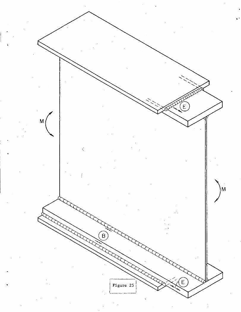
A wide variety of cover-plated beam details with tapered or
square ends are described in Figs. 23, 24 and 25. Stress Category E
applies to the base metal at the ends of the cover plates. The con
tinuous longitudinal fillet welds along the edges of the cover plate
are covered by stress Category B.
14

When discontinuous or intermittent fillet welds are used (see
Fig. 26) stress Category E is applicable at the end of each intermit
tent weld. This is a conservative treatment of intermittent·welds
because of the lack of test d~ta. It is probable that higher fatigue
strengths exist when the intermittent welds are continuous (i.e. web
to-flange connection) so that the connected plates are about equally
strained. Further work is needed to clarify this condition.
Beam girder intersections often result in low fatigue strength
details. This is shown in Figs. 27 to 30. Groove welded flange to
web or flange to flange joints can cause substantial reductions in the
~veb or flange bending stress range. Since the length of the weld
connecting the secondary beam to the web or flange will always be
greater than 4 inches, Category E applies. If a continuous web-to
·flange weld abruptly terminates as shmvn in Fig. 28, Category E is
also applicable. The stress gradient through the main girder depth
may result in stress ranges in the web that are low and not fatigue
critical at the floor beam compression flange in Figs. 27, 28 and 29.
A more critical condition is provided by the flange welds in Fig. 30.
When higher fatigue strengths are needed in either the main girder
or the cross girder, appropriate transitions can be used and the cross
girder flange can be made continuous and passed over the main girder
flange or through its web as illustrated in the detail shown in Fig.
28.
15
.. \ ....
Category F
Category F is applicable to the shear stress acting on the throat
of fillet welds. It applies to continuous or intermittent longitudi
nal or transverse weldments. These stress conditions are obvious and
at"e not shown in the Figures., , It is seldom that Catego-ry F controls
a design. Under normal design conditions, the shear stresses in the
weld are low enough to prevent cracks from forming in the weld.
Cracks form instead at the weld toe termination and propagate into the
connected material. Category F was derived from tests of small plate
specimens with specially designed welds15
which were purposely sub
jected to high shear stresses.
16

4. DETAILS MOST SUSCEPTIBLE TO FATIGUE
Of all the details shown in Figs. 1-30 those that fall into
stress Category E are the most susceptible to fatigue crack growth in
highway bridges. Existing studies of the stress history in bridges
have indicated that the stress range seldom exceeds 6 to 8 ksi. Hence
most details are never subjected to fatigue crack growth because the
stresses are below the crack growth threshold.
Only details that provide the lowest fatigue strength are likely
to experience crack growth. Details falling into Stress Category E
have the lowest fatigue strengths.
The designer has two major factors he can control. These are the
choice of detail and the design stress range. If a low strength de
tail is used, then every effort should be made to avoid locating the
detail in regions of significant cyclic stress. Alternately, the
stress range must be reduced to accomodate the detail which depends
on the selected cycle life. When details are located in compression
stress regions and no possibility of stress reversal exists, there is
no fatigue problem. Any crack growth will be limited to the residual
tensile stress zone unless out-of-plane deformations occur. The
crack will not affect the members behavior.
Details designed in accordance with the provisions given in the
Interim AASHO Specifications - 1974, will provide satisfactory per
formance and no appreciable amount of crack growth can be expected
throughout their life.
17
5. SIGNIFICANCE OF FABRICATION AND MANUFACTURING DISCONTINUITIES
Although only indirectly a part of connection design, discontinu-
ities from manufacturing or the fabrication process may be of concern
depending on their orientation with respect to the applied stresses
and their size and location. In general, if a discontinuity is in a
plane that is parallel to the line of applied stress, it has little
or no effect on the fatigue strength or performance of the member or
detail. Crack growth results only when a substantial amount of cyclic
tension from the applied loads crosses a planar region which contains
a discontinuity.
This section provides guidance to the designer on the signifi-
cance of conditions frequently encountered during fabrication and man-
ufacture.
(a) Rolled Plates and Shapes
In rolled structural plates and shapes the discontinuities may
be in the form of surface imperfections, irregularities in mill scale,
laminations, seams or inclusions. Generally laminations, seams and
inclusions have a microscopic thickness with respect to the direction
of rolling and hence have a negligible effect on a members behavior
when stresses are parallel to the direction of the discontinuity. Ex-
perimental fatigue studies have demonstrated that fabricated planes
of discontinuity that are parallel to the applied stress have. no de-
1 2 3 trimental influence on the fatigue behavior and strength. ' ' Even
small irregularly shaped pits in the flange or plate surface have
little effect and result in high fatigue strength. (Category A) An
18
example is the surface discontinuity shown in Fig. 3la. This beam
sustained 4,456,000 cycles at a 36 ksi stress range which placed it
near the upper confidence limit.1
Most discontinuities that are in planes parallel to the applied
stress~s are not injurious and should be left alone. Most attempts
to remove them will result in a condition that is worse than the ori-
gin~! discontinuity.
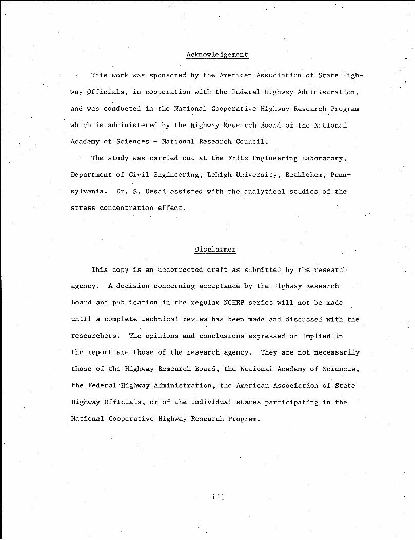
During fabrication nicks or notches may occasionally result from
handling devices. Smooth or flat discontinuities have little effect
since they do not result in a significant increase in stress concen
tration. However if a sharp severe notch condition results from
either fabrication or manufacture (see Fig. 3lb), it should be removed
or repaired to prevent an undesirable condition from developing. The
sharp gouge in the flange tip shown in Fig. 3lb resulted in failure
after 2,846,000 cycles at a 20.5 ksi stress range which was below the
threshold level for Category A. Frequently such discontinuities can
be removed by grinding out the notch to a smooth transition.
Sometimes surface imperfections occur in plates or shapes from
the manufacturing process which are repaired by welding and then
grinding the reinforcement off. 6 Typical surface and edge conditions
that are conditioned in this manner are mechanical gouges, scabs, sli
vers and large seams. Criteria for conditioning the plate is given in
Ref. 6. These repairs are usually very shallow and only a visual
check of the repaired surface is needed to insure that no severe sur
face discontinuity exist that is transverse to the applied stresses.
19
--.
Any micro-discontinuities that may exist in the repaired region have
no. significant influence on the members behavior because they are not
at locations of stress concentration and geometric change with the
reinforcement removed.
Occasionally a severe notch condition may occur at the flame-cut
edge of a plate as illustrated in Fig. 32. Fatigue tests of beams
with flame-cut edges have shown that an ASA roughness of 1000 or less
will not result in crack growth from the flame-cut edge prior to fail-
ure from discontinuities in the flange-web fillet welds of built-up
1 beams. - However, poor quality cutting can result in substantial re-
3 ductions in strength and much earlier crack growth. Obviously, if
high fatigue or fracture strength is desired, severe fla\vs that result
...... from flame- irregularity or other causes should be removed by grinding . . '
Inclusions sometimes exist in fine grained killed steels when a
highly refractory aluminum oxide is entrapped during solidification.
During slab rolling these non-metallic inclusions are extended long-
itudinally in the direction of rolling. When the slab or bloom is
rolled into a plate or a structural shape, further elongation and
some lateral spreading of these inclusions occur, resulting in in-
elusion stringers or clusters of stringers which are oriented in
elongated flat areas parallel to the rolled surfaces. These non-·
metallic particles are very small as illustrated in Fig. 33. Gener-
ally they are only 0.001 in. thick and 0.1 in. or less wide. These
types of discontinuities have no significant effect on the fatigue
strength (Category A) and performance of the material when they are
20
oriented parallel to the applied stress.
Figure 34 shows a fatigue fracture surface of a W36x300 rolled
beam which experienced fatigue crack growth at the end of a welded
7 cover plate. The fracture surface is in the beam section away from
the cover plate. Fatigue crack growth occurred at the weld toe and
penetrated into the flange perpendicular to the line of stress. An
inclusion condition existed at mid-depth of the flange and was defined
by ultrasonic inspection to be about 5-1/2 inches wide and running for
some length centered on the web. It is apparent in the photograph
that the inclusion intercepted the crack as it grew upward into the
flange perpendicular to the inclusion. The crack was forced to grow
around the inclusion as evidenced by the change in the fatigue crack
growth path. Figure 35 shows a ground and etched cross section about
1 inch from the fatigue crack surface. The etched cross section con-
firmed the presence of the inclusion condition. Since the dimension
of the inclusion perpendicular to the line of stress was extremely
small, the inclusion had no detrimental effect on the behavior of the
member. In fact, the orientation of the inclusion being parallel to
the line of stress was beneficial in this case since it served to
arrest the crack front.
An inclusion condition of this type would be of greater concern
if the member were subjected to forces perpendicular to the flange.
For example, if a structural element were attached perpendicular to
the direction of rolling and cyclical forces applied through the at-
tachment so that stresses are applied perpendicular to the rolled sur-
21
face, such an inclusion condition could be detrimental to the member's
performance.
Seams of laminations may result from rolling thick plates or
heavy shapes. Fortunately, they are usually in planes parallel to the
line of stress and do not affect a member's behavior or performance.
(b) Mechanically Fastened Joints and Members
In mechanically fastened (riveted or bolted) members and joints
the primary concern is with the drilled or punched holes needed for
the fasteners. Other discontinuities exist but are not critical. For
example, most mechanically fastened built-up members have multiple
plies which result in many planes of discontinuity between plates.
These planes are all parallel to the applied stresses and have no
effect on the member's strength or performance. Most laminations,
seams or inclusions can be considered comparable when they have a com
parable orientation. Tests on mechanically fastened built-up members
have shown clearly that the fabricated planes of discontinuity are not
a critical factor. Columns, beams and tension members are not affect
ed by their presence.
When drilled or sub-punched and reamed holes are used, a very
high fatigue strength generally results because the surfaces of the
reamed or drilled holes are smooth with very small initial discon
tinuities. These hole surfaces are similar to rolled surfaces of
plates and shapes as far as fatigue life is concerned.
The bolt clamping force in a high strength bolted joint assists
with the load transfer, and very often crack growth does not occur
22

8 9 at the bolt hole. ' Often a fretting condition occurs on the faying
surface which results in crack growth in the gross section as shown in
Fig. 36. The fatigue strength that results is almost as high as that
of the plain material. This high strength is made possible by the
high bolt clamping force which reduces the stress magnitude at the
very small-sized discontinuities at the bolt hole.
Punched holes can result in substantial reductions in fatigue
strength because of the imperfections introduced during punching as
illustrated in Fig. 37. If subjected to cyclic loading, a punched
hole is more likely to experience crack growth than a drilled hole. A
second factor of concern is the influence of the punching on the
toughness of the material in the immediate area of the hole. Studies
have indicated that substantial variation can be expected in notch
toughness and in the initial discontinuity condition from misalignment
of the punches or other fabrication factors.10
These conditions may
result in a brittle fracture from rapid crack propagation if cyclic
loading results in an enlargement of the initial cracks from punching
and a critical combination of crack size, stress magnitude and notch
toughness occurs. The situation is less severe for joints of high
strength bolts with their high clamping force.
Misplaced drilled holes have little effect on fatigue strength.
If they do not adversely influence static strength and maintenance
they should be left open or a bolt inserted. If it is necessary for
such holes to be welded shut care must be taken to insure that large
Helding discontinuities are not present. The same inspection criteria
23

. -
applied to transverse groove welds should be used to establish weld
soundness if such holes are w~lded shut. Welded up holes have caused
cracks to form \vhen such care was not exercised.
(c) Welded Details and Members
In welded built-up members of structures, small sharp discontin-
uities exist at the weld periphery or in the welds of both fillet and
groove welded details. In addition, many planes of discontinuity can
be induced by fabrication.
Whether or not these discontinuities are critical, and constitute
an initial crack condition that may grow, depends largely on their
orientation with respect to the applied stress. Fatigue studies of
welded members and details have provided insight into the crack growth
behavior of welded details.
Signes, et al. have shown that fatigue cracks initiating from
fillet weld toes start from small sharp intrusions of slag that ema-
11 nated from the welding flux or plate. These observations were con-
firmed by further studies conducted by Watkinson et al. who showed
12 that these discontinuities exist in all conventionally made welds.
These micro-flaws cannot be detected nor characterized by currently
used non-destructive inspection techniques.
All experimental evidence has confirmed that fatigue crack growth
from fillet-welded details normally initiates at the weld toe of a
weldment, starting from a micro-discontinuity when the applied stress-
. 1 2 3 es are perpendicular to the weld toe. ' ' This is illustrated in
Figs. 38, 39 and 40 v1hich show the cracks that formed in the beam
24

1 2 flange or web at the toes of a terminating fillet weld. ' The primary
difference between the details shown in Figs. 38, 39 and 40 is the ge-
ometrical stress concentration condition produced by the welded detail.
This is reflected in the fatigue strength of these details: the
stiffener and the short attachment have a higher fatigue strength
(Category C and D) than the cover plated beam. (Category E)
If tack welds are used to temporarily align or position plates
and are not incorporated into the final weld they should be treated as
any other welded detail. Tack welds that are parallel to the applied
stresses are more severe than those that are perpendicular because of
the geometrical effect of length. (They provide a Category C, D or E
design condition depending on their length). If used it is preferable
to place them in low stress regions or in the compression zone. Tack
welds that are incorporated into fillet or groove welds do not ad-
versely effect the joint. Their influence is already reflected in
the various design categories.
Fatigue cracks which occur in multiple coverplated beams form at
weld ends that are perpendicular to the direct.ion of applied stress.
As shown in Fig. 41 the fatigue crack growth is initially through the
primary cover plate at the terminating toe of the fillet weld. Crack
growth is arrested when it intersects the fabricated plane of discon-
tinuity between the primary plate and beam flange. Continued growth
of the crack can only occur if it is propagated into the beam flange
via the continuous longitudinal fillet weld connecting the primary
cover plate to the flange. The fabricated plane of discontinuity had
25
! ' ...
no detrimental influence on the fatigue behavior and strength of mul-
1 tiple coverplated beams. Their behavior is analogous to'the behavior
of multiple-ply bolted or riveted members.
In some types of welded joints fatigue cracks may initiate at
points other than the weld toe when the stress concentration effect is
not great at the toe. For example, in joints involving transverse
load-carrying fillet welds or transverse partial-penetration groove
welds, cracking can initiate at the weld root with propagation through
the weld as shown in Fig. 42. If the welds are sufficiently large and
their geometry satisfactory, with small initial cracks (lack of pene-
tration) these joints may not experience crack growth at the weld root
but at the weld toe (Category C). In these cases the condition at
· --':: '""· i · theiweld toe·-is more severe than' the condition resulting•from the fa-·
bricated partial penetration discontinuity.
Fillet welds connecting flange and web plates such as in the
· -. ... · '''plain·welded'beam are also structural details which experience fatigue··
crack growth from an internal weld discontinuity. The flange-web fil-
let welds often result in internal discontinuities. Porosity (gas
pockets) illustrated in Fig. 43 represents a typical initial discon-
tinuity. The lack of penetration in the web-flange joint constitutes
a discontinuity the full length of the member. This discontinuity is
parallel to the line of stress and has no influence on the fatigue
crack growth. Other sources of crack growth are at stop-start posi-
tions and weld repairs where incomplete fusion or trapped slag
exists.1
'2
Cracks starting at porosity and at the directly comparable
26
-(..
stop-start or weld repair locations were initially completely inside
the weld and were not visable from the surface until substantial crack
growth had occurred. These cracks took the shape of a disc and main-
tained this shape until the crack penetrated the flange and assumed a
three-ended crack shape. Most of the fatigue life was spent propa
gating the crack inside the weld. 1 •13
A directly comparable condition occurs in longitudinal groove
welds. In either continuous longitudinal fillet or groove welds, the
usual discontinuity such as porosity, incomplete fusion or trapped
slag results in a high fatigue strength (Category B). Unless these
d . . . . d 1 bl 1. . 14 h 1 ld 1scont1nu1t1es excee current y accepta e 1m1ts t ey s wu not
be removed since the resulting repair will often result in a worse
d . . 1,3 con 1t1on.
The fatigue strength is governed by discontinuities that are per-
pendicular to the applied stresses not by those that are parallel.
Hence, the inspection criteria used for fillet welds is equally appli-
cable to longitudinal groove welds. Generally this includes a visual
inspection with some magnetic particle examination to determine wheth-
er or not cracks are in the welds. Ultrasonic and·radiographic in-
spection are not necessary for longitudinal welds. Large internal
discontinuities that are perpendicular to the applied stresses are not
possible as would be the case with transverse groove welds in the
web or flange.
Transverse groove welds with the reinforcement in place result
in a stress concentration at the weld toe. This stress concentration
27

is associated with small discontinuities at the weld toe and is usu-
ally I;Uore severe (Category C)·than the condition caused-by other minor'
internal flaws (Category B). This is particularly true if a severe
geometrical stress concentration exists at the weld toe as in a flange
attachment.
It has been common practice in bridge construction to provide
non-destructive inspection of groove welds transverse to the applied
stresses so that the internal flaw can be minimized. This coupled
with the removal of the weld reinforcement minimizes the stress con-
centration and toe discontinuity. Crack growth generally initiates
in these cases at a mechanical notch in the flange plate or in the
longitudinal flange-web fillet weld. The fatigue strength thus cannot
exceed that of the plain welded beam.1
If the internal groove weld discontinuities such as lack of pen-
etration, slab inclusions and other conditions are comparatively large
' • :; r"' . in size' in· a ·plane' perpendicular· to. the stress field' ·crack growth is
. . . 1 h 1 . 3,14 more cr1t1ca at t ose ocat1ons. The orientation of the internal
discontinuities is of primary importance. Only those discontinuities
that are perpendicular to the applied stress are critical. Studies
by Gurney and Harrison have shown that when slag inclusions were par
allel to the applied stress, they had little if any effect.3
The fa-
tigue strength was not impaired (Category B) and crack growth did not
occur. For example, the discontinuities shown in Fig. 4 are long
alumina stringer inclusions. They are oriented parallel to the line
of stress and have no appreciable influence on fatigue strength. If
28
• - 4-,..; .,_;.. . -

their width perpendicular to the line of stress is substantial they
will have a deleterious effect.
29
•.
6. REFERENCES
1. Fisher, J. W., Frank, K. H., Hirt, M.A. and McNamee, B. M.
2.
. .~ ...... - r--~-· .L-,'l
3.
4.
5.
6.
- ! ,._
7.
EFFEClf OF WELDMENTS·ON 1'HE FATIGUE STRENGTH OF STEEL:BEAMS, NCHRP Report 102, Highway Research Board 1970.
Fisher, J. W., Albrecht, P. A., Yen, B. T., Klingerman, D. J. and McNamee, B. M.
FATIGJJE. s:rRENG.TH_ OJ:\ Sl'EEL BEAMS WITH TRANSVERSE. STIFFENERS AND ATTACHMENTS, NCHRP Report 147, Highway Research Board, 1974
Gurney, T. R. FATIGUE OF WELDED STRUCTURES, Cambridge University Press, 1968.
Ozell, A. M. and Conyers, A. L. TRANSFER OF STRESSES IN WELDED COVER PLATES, WRC Bulletin No. 63, 1960.
Mueller, J. A. STRESSES IN COVER PLATES AND BEARING STIFFENERS, WRC Bulletin No. 63, 1960.
ASTM A6-73 Standard Specification for GENERAL REQUIREMENTS FOR DELIVERY OF ROLLED STEEL PLATES, SHAPES, SHEET PILING, AND BARS FOR STRUCTURAL USE, ASTM, Philadelphia, 1973.
Bowers, D. G. LOADING HISTORY OF SPAN 10 ON YELLOI-J MILL POND VIADUCT, Highway Research Record No. 428, Highway Research Board, 1973.
c ..... l~Jt.~-~ttf-~-1~:~~81 .... ~ }3irkem.oe~,.,P.·:C.t, Meinheit~ D. f., and Munse, W. H. 1 ·' - 11·~·!. I·~~-·
FATIGUE OF A514 STEEL IN BOLTED CONNECTIONS, Journal of the Structural Division, ASCE, Vol. 95, No •. STlO, Oct. 1969.
9. Steinhardt, 0., and Mohler, K. TESTS ON THE APPLICATION OF HIGH-STRENGTH BOLTS IN STEEL CONSTRUCTION, Part III, (in German) Berichte des Deutschen Ausschusses fur Stahlbau, Stahlbau-Verlag Ginbh, Heft 24, 1962.
10. Stout, R. D., Tor, S. S., and Ruzek, J. M. THE EFFECT OF FABRICATION PROCESSES ON STEELS USED IN PRESSURE VESSELS, Welding Research Supplement, Vol. 30, No. 9, September 1951.
11. Signes, E. G. , Baker, R. G. , Harrison, J. D. and Burdekin, F. M. FACTORS AFFECTING THE FATIGUE STRENGTH OF WELDED HIGH STRENGTH STEELS, British Welding Journal, Vol. 14, March 1967.
30
12. Watkinson, F., Badger, P. H., and Harrison, J.D. THE FATIGUE STRENGTH OF WELDED JOINTS AND METHODS FOR ITS IHPROV~fENT, Proceedings, Fatigue of Welded Structures Conference, The Welding Institute; England, Paper No. 7, Vol. 1, 1971.
13. Hirt, lvl. A. and Fisher, J. W. FATIGUE CRACK GROHTH IN WELDED BEAH, Engineering Fracture Hechanics, Vol. 5, pp. 415-429, 1973.
14. Hunse, W. H. and Grover, L. H. FATIGUE OF WELDED STEEL STRUCTURES, He1ding Research Council, New York, 1964.
15. Wilson, H. H. FATIGUE STRENGTH OF FILLET-HELD AND PLUG-HELD CONNECTIONS IN STEEL STRUCTURAL lvl~BERS, Engineering Experiment Station Bulletin No. 350, University of Illinois, Vol. 41, No. 30, lvlarch, 1944.
31

TABLE 1
(MSHO TABLE 1. 7. 3B)
Allowable Range of Stress, F (ksi) sr
.. Category - . . - ··-~ ... .. -
See Table 2 For For For For over 100,000 500,000 2,000,000 2,000,000
Cycles C_y_cles Cycles Cycles
A 60 36 24 24
B 45 27.5 18 16
c 32 19 13 10
D 27 16 10 7
E 21 12.5 8 5
F 15 12 9 8
In Table 1.7.3C, "T" signifies range in tensile stress only; "Rev." signifies a range of stress involving both tension and compression during a stress cycle.
32
,I

General Condition
Plain
Built-up
Groove Welds
TABLE 2
(AASHO TABLE 1.7.3C)
Situation
Base metal with rolled or cleaned surfaces. Flame cut edges with ASA smoothness of 1000 or less
Base metal and weld metal in members without attachments, built-up of plates or shapes connected by continuous full or partial penetration groove welds or by continuous fillet welds parallel to the direction of applied stress
Calculated flexural stress at toe of transverse stiffener \V"elds on girder webs or flanges
Base metal at end of partial length welded cover plates
Kind of Stress
T or Rev.
T or Rev.
T or Rev.
having square or tapered · T or Rev. ends, with or without welds across the ends.
Base metal and weld metal at full penetration groove welded splices of rolled and welded sections having similar profiles when welds are ground flush and weld soundness established by non-destructive inspection.
33
T or Rev.
Stress Category (See
Table 1.7.3B)
A
B
c
E
B

General Condition
Groove weld (cont'd)
TABLE 2 (Continued)
Situation
Base metal and weld Metal in or adjacent to full penetration groove welded splices at transitions in width or thickness, with welds ground to provide slopes no steeper than 1 to 2~, with grinding in the direction of applied stress, and weld soundness established by non-destructive inspection
Base metal and weld metal in or adjacent to full penetration groove·welded splices, with or without transitions having slopes no greater than 1 to 2~ when reinforcement is not removed and weld soundness is established by non-destructive inspection
Base metal at details attached by groove welds subject to transverse and/ or longitudinal loading
Kind of St:ress<1)
T. or Rev.
T or Rev.
when the detail length, L, T or Rev. parallel to the line of stre5s is between_2 .·in. and 12 times the plate thickness, but less than 4 in.
Base metal at details attached by groove welds subject to transverse and/ or longitudinal loading when the detail length L T or Rev. is greater than 12 times the plate thickness or greater than 4 in. long
34
Stress Category
(See Table 1)
B
c
D
E

General Conditions
Fillet Welded Connections
!Mechanically Fastened Connections
TABLE 2 (Continued)
Situation
Base metal at intermittent fillet welds
Base metal adjacent to fillet welded attaclments with length L in direction of stress less than 2 in. and stud-type shear connectors
Base metal at details attached by fillet welds with detail length L in direction of stress between 2 in. and 12 times the plate thickness but less than 4 in.
Base metal at attachment details with detail length L in direction of stress (length of fillet weld) greater than 12 times the.plate thickness or greater than 4 in.
Base metal at gross section of high strength bolted slip resistant connections, except axially loaded joints which induce out-of-plane bending in connected material
Base metal at net sec-tion of high-strength bolted bearing-type connections and other mechanically fastened joints
35
Kind of Stress
Tor Rev.
T or Rev.
T or Rev:.
T or Rev.
T or Rev.
T or Rev.
Stress Category
(See Table 1)
E
c
D
E
B
B

TABLE 2 (Continued)
[Fillet Welds Shear stress on throat of fillet welds Shear F
36

l .~ i
;
1 l
1 l
Figure 1
>:t"}:~:= '.: \· · ··'i~~j?~(~~: .· ~ .·· . . .. - . . '
·:-.··· .. '"'•·~ .. ~ . ..,. '
·.~·

l l l l l I
j
1 I
I f I
l I I
I . '
'; '·
· .. -'. '·' .
. ' .:~ ...
.· ,_,

I ~-
I I
. .
- .... <· ,.-'/' ' .. '~ ...... - .,._, '~ ..
~ ~;· .' ·.~---~ ' .. ----·-.
._._ ..... · .- ·- .
·Nondestructive · Inspection (NOT) Ground Flush (reinforcement removed)
NDI and not Ground Flush
Figure 3 I I

./
"~.-;:~·:·:;· :\:· ~<--· .. . _.
~ .. =-... ..
- r-:· . .- ·:: . ..• . ..~ ... . ~:. . '.
Groove Weld ..,_,__ Web Splice Ground Flush with NDI of tension portion of Web
®
-.......
· Figure 4
©
Groove Weld
.Web Splice not Ground Flush with NDI of tension
portion of Web

I ·,
j .
1 l
NDI and Ground Flush
Slope not Greater than
·1 in 2 ~2
NDI and
..
not Ground Flush
Figure 5
)M
I
I !
.j
l.
l l I
·l j l I .j
l 1 I 1 I
I ! i l l 1
NDI and Ground Flush ·
Slope ·not
Greater than
I in 2 lt2
Figure 6
NDI and not Ground Flush
. I . I
l l I" ! ' i I
1 {
i
NDI and . Ground Flush
Slope not Greate·r than I in 2 lf2 --===:::::::::======~;!_......__
NDI and not Ground Flush
·or+·.
Figure 7
... ~ .· ,. . . . ' ..=·-· .
. · ..

' l. l 1
i '
l I '
_ Note: * radius transition . with the weld termination ground smooth
V®R=O ©* 24>R>6in.
Stiffener
Figure 8
~End of Stiffener
'Gusset
Sec. A-A
All Groove Welds NDI and Ground Flush when perpen_dicular to applied stress
. I
i I
1-1 I
l
Taper I
Manhole . Top fP.. only
R~2'-0 11
Typ.
i• ·:
_® ®
~~~-=r = _.._,.l$'::"ri~'=""=~ • ,.,.,~,;r.e;;.;~--L, ~ __ ,__ ·=....-,
,, II
••
·or+-
(t Bott. Chord
NDI groove welds when stresses are perpendicular to weld
Figure 9

j l I
l ·l
I ! '
1 i I ! 1 I
l l
! I
I
:l
I l i
I I
NDI and.· Ground Fl ush
Figure 10
As Weldedand NDI
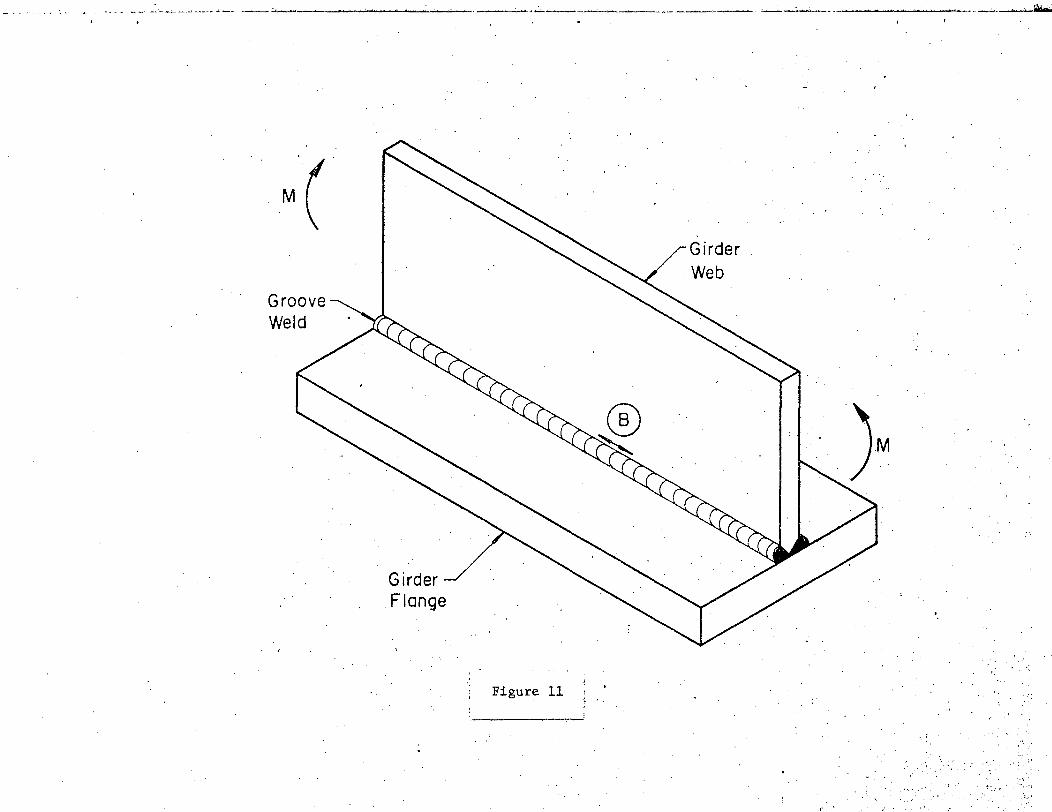
M( Groove Weld
Girder Flange
! • Figure 11 ~ ..
Girder . . Web
.:..--- .... ~· -· _. -------
. '·
.. · .. · .·. _,··:. ':··.
. ~ :. ' ·· ... ; ,•·,

i 1 j l
I 1 l j
... ' i j
i . !
i '
l ' I I ' .,
i.
i ··;
1
l
I 1
·.J
i
. I I '
' ... !
or -fE-
Figure 12

. i I
'
J
1
l· I
( 4-6) tw
Figure 13
·I . . .
l
, l _, l
•j l . l . I i l
I l
(4-6}tw
Figure 14

., . ..
~ .
' I •
j
I t I -
1
l . '. I
I
I I
j
j ·'
Figure 16 I I
...
i I ,
1
1 1
l 1 l
·' "'
1 j 1 -
\ ! r l
1 1 1 1 i
Figure 17
.;
'
~ j : i i 1 ,. i
·1
i 1
1
!
Gusset
@)L<2in.
@ 2in.<L<4in.
® L.>4in. ~
Groove or Fillet Weld
0 ~.
Figure 18
@L<2in.
@2in<L
@L>4in. ~
in.
.. :.
@ L<2-in.
@ 2in.<L<4in.
-- . 9QO
Figure 19 ~
L>4in.
l I I
I 1 I I j i
1
j
I ., I j j I l j
I l 1 I j
I I
M
R Category
R> 24in. 8
24>R >6 in. C
0 E
Note: The weld end must be ground smooth at the transition radius.
Figure 20

W L<2in.
@ 2in.<L<4in.
Gusset
@)L<2in.
M

J
Gusset
...

! ., i
End not Welded
Cover Plate with
Tapered Ends
-.

End not Welded
j
Cover Plate with Square End~
. ~· ··1 Figure 24
. .' -~-............ ~·.-,.-!
-· - .
~-- -----~---1 --
1 Figure 25l 1 I -----~~-~--.~1
••

I Figure~i -~~-~~~

Main Girder
-. NDI and not Ground
Web Cleat not Shown
Flush
Secondary Beam (rolled shape)
Rolled Beam cut-out
.:...__ .............__ ~.,.._. - -• . ·- ...___~ ~ ·....... ~··· ... - ' ~-- - . - ~ . . .,._ ... - .. ,. -... ..-· - '

NDI and Ground Flush
)
not Shown
Secondary Beam
// //
/
•
Web Cleat not Shown
Secondary Member or Diapham (rolled shape)
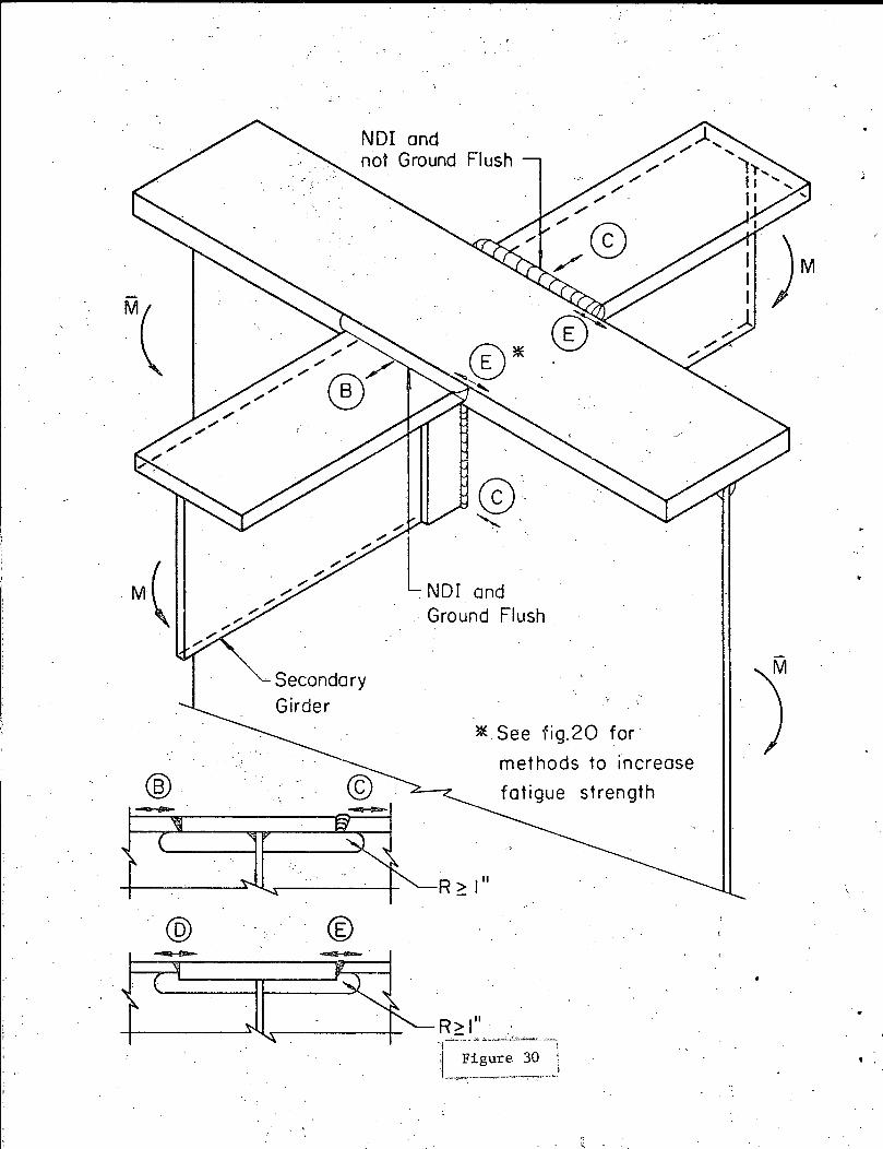
®
"@
NDI and not Ground
· Secondary
Girder
® -·
and Ground Flush
* See fig.20 for
methods to increase
fatigue strength
R ~ I"

•
•
From discontinuities in
(b) From sharp gouge in flange tip.
Fig . 31 Typical fatigue cracks initiating from surface flaws
Fig. 32 Fatigue crack at flame cut flange-tip of beam
Fig. 34 Fatigue crack surface of rolled beam at end of welded coverplate -inclusion condition ·at mid-thickness of flange
Fig. ~3 Etched surface of steel plate showing non-metallic inclusion stringers
-- -~-""::'~---- -~ • - -···-- .. ·'tt·-~~ ... - · .;:.,.. :-:-~-
,. :..' ~ . - ~ .... :..:.:.:-._--1.~ .. :; ;::;-....~';-;~ -::·~~-
Fig. 35 Etched cross-section showing inclusion condition at mid-thickness
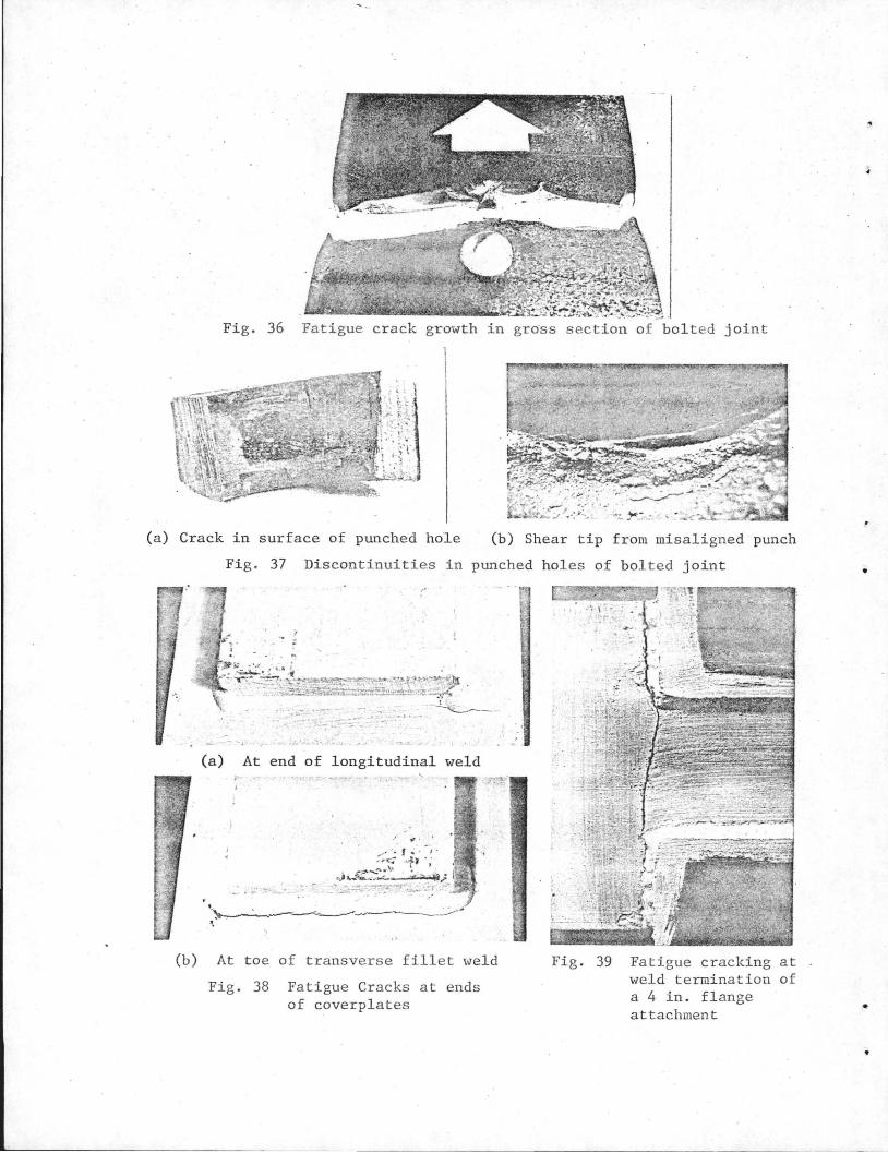
Fig. 36 Fat igue crack growth in grass section of bolted joint
(a) Crack in surface of punched hole (b) Shear tip from misaligned punch
Fig . 37 Discontinuities in punched holes of bol ted joint :
~~~ #~:-.:~~~,~~~0~~~~~~~,:~·:~~·: '~ -~-
.......
'· --- :;-_
(a) At end of longitudinal weld
., . .,
... - • ,. ¥
- ... - ....... --~-~..... -
(b) At toe of transverse fillet weld
Fig. 38 Fatigue Cracks at ends of coverplates
·'
Fig. 39 Fatigue cracking at weld termination of a 4 in . fl ange attachment
•
•
•

1 I
Fig. 40
)
Fig. 42
' •
•
•
Fatigue crack at weld toe of a transverse stiffener
Fig. 41 Fatigue crack growth in multiple coverplated beam at unwelded end of secondary coverplate
Fatigue crack growth from Fig. 43 root of partial penetration load-carrying fillet welds
r-------
I
I L
Crack initiation from gas porosity in web-flange fillet welds
I t-l ~--
_ _J
Fig. 44 Al~mina stringer inclusions in ~ plate adjacent to grove weld
-