11a. Electrical Specifications - General
86
PRPOSED COMMERCIAL DEVELOPMENT FOR MR. ALI SALEH. T. NASSER AL NEYADI ME-9 PLOT C-128 MUSSAFAH- ABU DHABI, U.A.E FILE NO. 1074 1-ELECTRICAL SPECIFICATIONS - GENERAL INDEX 1 of 2 ELECTRICAL SPECIFICATIONS 1- GENERAL SPECIFICATIONS
Transcript of 11a. Electrical Specifications - General
8/10/2019 11a. Electrical Specifications - General
http://slidepdf.com/reader/full/11a-electrical-specifications-general 1/86
PRPOSED COMMERCIAL DEVELOPMENT FORMR. ALI SALEH. T. NASSER AL NEYADIME-9 PLOT C-128 MUSSAFAH- ABU DHABI, U.A.E
FILE NO. 1074
1-ELECTRICAL SPECIFICATIONS - GENERAL INDEX 1 of 2
ELECTRICAL SPECIFICATIONS
1- GENERAL SPECIFICATIONS
8/10/2019 11a. Electrical Specifications - General
http://slidepdf.com/reader/full/11a-electrical-specifications-general 2/86
8/10/2019 11a. Electrical Specifications - General
http://slidepdf.com/reader/full/11a-electrical-specifications-general 3/86
PRPOSED COMMERCIAL DEVELOPMENT FORMR. ALI SALEH. T. NASSER AL NEYADIME-9 PLOT C-128 MUSSAFAH- ABU DHABI, U.A.E
FILE NO. 1074
1- ELECTRICAL SPECIFICATIONS – GENERAL ELECTRICAL WORKS 1 of 60
ELECTRICAL SPECIFICATIONS
1- GENERAL SPECIFICATIONS
8/10/2019 11a. Electrical Specifications - General
http://slidepdf.com/reader/full/11a-electrical-specifications-general 4/86
PRPOSED COMMERCIAL DEVELOPMENT FORMR. ALI SALEH. T. NASSER AL NEYADIME-9 PLOT C-128 MUSSAFAH- ABU DHABI, U.A.E
FILE NO. 1074
1- ELECTRICAL SPECIFICATIONS – GENERAL ELECTRICAL WORKS 2 of 60
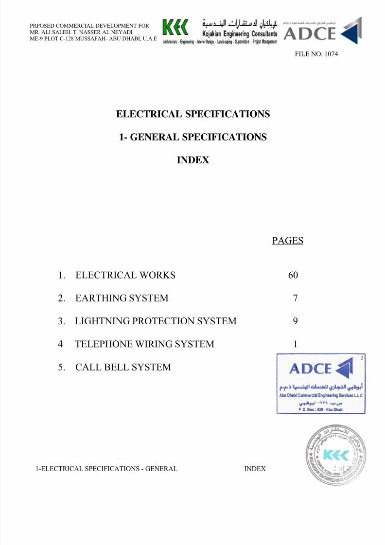
ELECTRICAL WORKS
INDEX
1.0 GENERAL1.02 SCOPE OF WORK1.03 GEN. CONDITIONS AND REGULATIONS1.04 OPERATING CONDITIONS1.05 DESIGN CONDITIONS1.06 STANDARDS1.07 SAMPLES1.08 NAME PLATES AND CHARTS1.09 AS FITTED DRAWINGS1.10 RECORD DRAWINGS AND OPERATING MANUALS1.11 MAINTENANCE AND SERVICING1.12 NOTICES
1.13 LABELS AND IDENTIFICATION MARKS1.14 SITE TESTS1.15 POWER SUPPLY TO A.C., MECH. AND SPECIAL EQUIPMENT1.16 APPROVAL OF DRAWINGS AND DIAGRAMS1.17 DRAWINGS AND SAMPLES1.18 MAIN L.V. DISTRIBUTION PANEL BOARDS1.19 DISTRIBUTION BOARDS1.20 LOAD CENTERS1.21 AUTO CHANGE OVER CONTRACTORS1.22 MOTOR CONTROL CENTRES1.23 SUB MAIN DISTRIBUTION BOARDS1.24 AUTOMATIC TRANSFER SWITCH “ATS”
1.25 AUTOMATIC POWER FACTOR CORRECTION CAPACITOR BANK1.26 BUS WAY HOUSING1.27 TRUNKING1.28 FEEDERS1.29 CONDUIT BOXES1.30 LIGHTING & POWER INSTALLATIONS1.31 TELEPHONE SYSTEM1.32 SATELLITE SMATV SYTEM1.33 LIGHTING INSTALLATION AND FITTINGS1.34 LAMPS1.35 POWER INTAKES1.36 VIDEO INTERCOM1.37 CAR ENTRANCE / EXIT BARRIERS1.38 GENERATING SYSTEM1.39 ELECTRIC MOTORS & MOTOR STARTERS
8/10/2019 11a. Electrical Specifications - General
http://slidepdf.com/reader/full/11a-electrical-specifications-general 5/86
PRPOSED COMMERCIAL DEVELOPMENT FORMR. ALI SALEH. T. NASSER AL NEYADIME-9 PLOT C-128 MUSSAFAH- ABU DHABI, U.A.E
FILE NO. 1074
1- ELECTRICAL SPECIFICATIONS – GENERAL ELECTRICAL WORKS 3 of 60
ELECTRICAL WORKS
1.01 GENERAL
The information supplied in this Specification is to assist the Contractor inunderstanding the scope of the Electrical Work, materials, equipment or servicesand those not specifically mentioned in this section but mentioned or implied inother sections of these specifications or elsewhere or indicated on the drawingshave also to be included in the Contractor’s price.
In addition to the following, the Contractor has to satisfy all the Conditions,Specifications and Requirements of ADDC.
1.02 SCOPE OF WORK
The Contractor shall furnish all labour, materials, equipment, tools, services,temporary works and storage necessary to completely supply, install, test, run,handover in a good working condition, and maintain during the guarantee periodthe following electrical system as detailed on the drawings.
- Main Boards, Sub Main Distribution Board (SMDB) and secondary distribution boards (DB).
- Trunking- All feeders from MDB to the DB’s and electrical equipment.- All conduits, boxes, etc. related to electrical installations specified hereafter.- Lighting & power installations, including power for all other trades.- Empty conduits, trunking, boxes and accessories required for the telephone
system in coordination with the Abu Dhabi Telephone Authority.- Mounting height.- Light Fittings and fixtures- Main earthing of the building.- All works related to main power intakes in coordination with Abu Dhabi Water
and Electricity Department (W.E.D.)- Intercom system- M.A.T.V. system- Fire alarm & Fire Detection System- Electrical Motors and Motor Starters.
8/10/2019 11a. Electrical Specifications - General
http://slidepdf.com/reader/full/11a-electrical-specifications-general 6/86
PRPOSED COMMERCIAL DEVELOPMENT FORMR. ALI SALEH. T. NASSER AL NEYADIME-9 PLOT C-128 MUSSAFAH- ABU DHABI, U.A.E
FILE NO. 1074
1- ELECTRICAL SPECIFICATIONS – GENERAL ELECTRICAL WORKS 4 of 60
1.03 GENERAL CONDITIONS AND REGULATIONS
All electrical work shall be carried out in a neat workmanlike and efficientmanner to fulfill the true meaning and intent of the Specifications and drawings.
All electrical work shall be carried out in accordance with the latest issue of theRegulations published by the Government of Abu Dhabi, Department of Waterand Electricity and latest edition and Rules and Regulations for buildings by theInstitution of electrical Engineers (I.E.E.), London.
All equipment and materials shall be in accordance with the latestrecommendations of the U.A.E. Regulations or B.S.S.
All equipment, including circuit breakers, relays, cables, etc. shall be designedfor or be rated for a continuous services under high humidity and ambienttemperature of 50 Deg. C.
1.04 OPERATING CONDITIONS
The declared supply system of the local Supply Authority is 415/240 Volts, 3- phase, 4-wire, 50 Hertz.
All electrical equipment shall be good for operation at a variation of plus orminus 5% on voltage and plus or 2% on frequency.
1.05 DESIGN CONDITIONS
All equipment shall be of the latest model; shall be designed to be suitable forthe climatic conditions (humidity, temperature, etc) at the site and shall be ratedfor continuous duty.
1.06 STANDARDS
All works under the contract shall be executed to conform to the best principlesof modern practice and shall generally be in accordance with the 15th. edition,inclusive latest amendments, of the Regulations for the Electrical Equipment ofBuildings issued by the Institution of Electrical Engineer, U.K., but shall in noway conflict with current rules, recommendations, regulations and requirementsof the Water & Electricity Department of Abu Dhabi.
1.07 SAMPLESThe Contractor shall submit of all materials and fittings to the Engineer andobtain his approval in writing before commencing any part of the works.
All materials shall manufactured by approved manufacturers.
1.08 NAME PLATES AND CHARTSAll equipment shall be identified by a permanently attached nameplateindicating the manufacturer, rated capacity, temperature and other limitations inArabic and English. All distribution boards shall have lettered charts inside thecover to show the services of every circuit breaker.
8/10/2019 11a. Electrical Specifications - General
http://slidepdf.com/reader/full/11a-electrical-specifications-general 7/86
PRPOSED COMMERCIAL DEVELOPMENT FORMR. ALI SALEH. T. NASSER AL NEYADIME-9 PLOT C-128 MUSSAFAH- ABU DHABI, U.A.E
FILE NO. 1074
1- ELECTRICAL SPECIFICATIONS – GENERAL ELECTRICAL WORKS 5 of 60
1.09 AS FITTED DRAWINGSDuring the course of the works the Contractor shall maintain a fully detailedrecord of all changes to the tender drawings so as to ensure easy and accurate
preparation of all the drawings as a true record of the actual installation.
The drawings shall show the complete electrical installation of all the workswithin and external to the buildings, etc. including the sizes and runs of allcables, the precise locations of all cables which may be buried within thestructure and those of any external cables which are buried directly in theground. The location and depth of all underground cables at the various entry
points shall also be clearly indicated.
1.10 RECORD DRAWINGS AND OPERATING MANUALSBefore acceptance of the works by the Engineer, the Contractor shall be requiredto demonstrate and explain to the client’s staff, the operation of all the electricalinstallations, and also the method of starting, running and stopping of allmechanical plant, and the correct method of operating P.A. Equipment, Fire
Alarm Systems, etc.Within one month of the completion of the installation, the Contractor shall
provide complete sets of record, drawings and operating manuals as follows:
a) General arrangement of all services as fitted to a scale of not less than1:100 metric.
b) Details of all items of plant and equipment including name and address ofthe respective manufacturer, type and model, serial number, duty, ratingand any other pertinent information.
c) Single line schematic drawings to a scale not less thank 1:100, indicating position of all distribution boards, switches, etc. together with relevantnotes describing their purposes.
The Contractor shall submit to the Engineer one complete set of all recorddrawings and manuals for his study and approval. After obtaining approval inwriting, the Contractor shall provide one negative and two black and white
prints of each drawing together with tow bound sets of all manuals andoperating instructions to the Engineer for issuing to the Client.
1.11 MAINTENANCE AND SERVICING
The Contractor shall be required to provide maintenance, servicing andreplacement of all defective parts during the maintenance guarantee period fromthe date of acceptance tests carried out by the Engineer.
1.12 NOTICES
In each L.V. Switch Room the following Notices relating to importantinstructions and information shall be provided and hung in a conspicuous place:
a) The instruction for the treatment of electric shock, in Arabic and in Englishlanguage, enameled on steel frame and screwed to the switch room wall.
8/10/2019 11a. Electrical Specifications - General
http://slidepdf.com/reader/full/11a-electrical-specifications-general 8/86
PRPOSED COMMERCIAL DEVELOPMENT FORMR. ALI SALEH. T. NASSER AL NEYADIME-9 PLOT C-128 MUSSAFAH- ABU DHABI, U.A.E
FILE NO. 1074
1- ELECTRICAL SPECIFICATIONS – GENERAL ELECTRICAL WORKS 6 of 60
b) A schematic diagram of the Plant located in the room together with a completeoutline single line Schematic drawing of the complete electrical distributionsystem, framed and mounted on the wall.
1.13 LABELS AND IDENTIFICATIONS All equipment and apparatus shall permanently with the Manufacturer’s name,and shall also be identified by engraved “Traffelyte” labels to indicate theservices controlled or to identify individual apparatus or equipment. Labels shall
be securely fixed to the front over of equipment in an approved manner.
1.14 SITE TESTS
The Contractor shall carry out the electrical tests on all sections of the works inthe presence of the Engineer and the representative of the Water & ElectricityDepartment.
The Contractor shall submit to the Engineer for approval the results of all testson completion two copies of test certificates forms as prescribed by Water &Electricity Department.
The tests shall include the following:
a) Continuity tests, for wire and cables. b) Insulation resistance tests, phase and phase to earth on all circuits and
equipment, using 1000 volts megger. The megger reading shall not be less thanthose specified in the British I.E.E. regulations and local authority requirements.
c) Operational tests of the equipment and systems.d) Operating of all and power circuits with load balancing.
All the above mentioned tests shall be carried out by the Contractor and anydamage resulting from the tests shall be repaired and/or damaged materialreplaced all to the entire satisfaction of the Engineer and at the Contractor’s ownexpense.
10.15 POWER SUPPLY TO AIR CONDITIONING, MECHANICAL ANDOTHER SPECIAL EQUIPMENT
The Contractor shall supply power as required to all equipment and provide
isolators, whether shown on the drawings or not. The Contractor shall ensureclose liaison between trades in respect of the wiring for the interconnection ofmotor control boards or isolators to the various items of equipment and controlsand the motor control boards.
8/10/2019 11a. Electrical Specifications - General
http://slidepdf.com/reader/full/11a-electrical-specifications-general 9/86
PRPOSED COMMERCIAL DEVELOPMENT FORMR. ALI SALEH. T. NASSER AL NEYADIME-9 PLOT C-128 MUSSAFAH- ABU DHABI, U.A.E
FILE NO. 1074
1- ELECTRICAL SPECIFICATIONS – GENERAL ELECTRICAL WORKS 7 of 60
1.16 APPROVAL OF DRAWINGS AND DIAGRAMSThe drawings supplied with the tender show the location of lighting fittings,sockets, switches, apparatus, etc. only they are approximate. The Contractorshall be responsible for the exact locations and to watch and fit the Architecture,other services and requirements.
Within 45 days from the date of signing the Contract, the Contractor shall prepare necessary electrical switchgear diagram, load schedules, etc., inaccordance with the Rules and Regulations of Local Authority and submit 5 setsof drawings to the Engineer for obtaining approval.
The Contractor shall be responsible for any discrepancies, error or omissions inthe drawings and other particulars have been approved or not by the Engineer.
1.17 DRAWINGS AND SAMPLES
1.17.1 General
This section should include for all drawings, information, progress charts andsamples which must be “Specifications” and as requested by the Engineer. The progress charts to be submitted for this section shall be closely coordinated withother progress charts for works.
1.17.2 Architect’s DrawingsThe Architect’s drawings issued with these Specifications indicate theapproximate locations of all electrical equipment and accessories. Exactlocations shall be shown in the drawings to be submitted by the Contractor forthe Engineer’s approval.
Wiring layouts and circuit routings shall also be shown on the shop drawings.
The Contractor shall check all architectural, structural, plumbing, airconditioning and ventilating drawings to avert any possible installation conflictsand secure the Engineer’s approval for any necessary adjustments.
1.17.3 Shop Drawings
The Contractor shall prepare and submit detailed shop drawings for allequipment, services distribution cables, wires and circuit routing.
The work described on any shop drawing submitted shall be carefully checked by the Contractor for all clearance, field conditions, maintenance of architecturalconditions and proper coordination of all trades on the works.
No payment shall be made for any variations or alteration on site due to lack ofknowledge of other trades. Any unresolved conflict between trades shall refer tothe Engineer for decision.
Equipment layout is to be detailed on the drawings showing the exact method ofinstallation and clearly illustrating components to be used in making allconnections. Drawings for Electric Room, M.D.B’s and M.C.C.B’s shall besubmitted to a scale of 1:5 showing exact location, feeder cables, space requiredfor same, trunking connections, etc. Details of supports, floor-ducts and cableconnection shall be to a scale 1:10.
8/10/2019 11a. Electrical Specifications - General
http://slidepdf.com/reader/full/11a-electrical-specifications-general 10/86
8/10/2019 11a. Electrical Specifications - General
http://slidepdf.com/reader/full/11a-electrical-specifications-general 11/86
PRPOSED COMMERCIAL DEVELOPMENT FORMR. ALI SALEH. T. NASSER AL NEYADIME-9 PLOT C-128 MUSSAFAH- ABU DHABI, U.A.E
FILE NO. 1074
1- ELECTRICAL SPECIFICATIONS – GENERAL ELECTRICAL WORKS 9 of 60
1.18.3 Busbars
Bus bars are hard drawn copper bar throughout and fully fault braced and ASTAcertified to withstand thermal and mechanical stresses arising from a maximumfault level of 50 KA RMS symmetrical for 3 seconds, 80KA for 1 second.
The main busbars are fully rated. The main neutral bar is 100% rating and aseparate continuous earth bar rated at 25% of the main busbar rating.
Bracing is achieved by means of injection moulded glass filled polyesterinsulation, high tensile bolts and Belleville washers. Busbar jointing isachieved by single or double bolt per phase and Belleville washers to giveconsistent torque per joint. All bars are phase taped where necessary foridentification.
1.18.4 Glanding Arrangements
All bottom plates of the switchgear will comprise a vermin barrier plate and
centre aluminum gland plate, for single core cables will be provided.
1.18.5 Incoming Sections
Main incoming sections will be provided for top or bottom cable entry andequipped within main ACBs.
1.18.6 Air Circuit Breakers
Air circuit breakers will be as follows:
3 pole, manula /draw out complying with BS 4752/IEC-157 part 1 P1 and P2duty. ACBs will have a P2 rating minimum of 50 KA.
1.18.7 Bus Coupling Sections
Bus coupling sections will be provided on their own incoming sections. Theywill comprise individually mounted ACBs, 3 pole with solid neutral links.
1.18.8 MCCB Branch Feeder Section
The branch feeder section will accommodate plug-in MCCBs up to 125OA TP.
Branch circuits above 125OA will comprise individually / dual mounted circuit breaker in a single section.
All ratings of MCCB’s at 415/240V 50 Hz to BS 4752/IEC-157 part 1 P1 duty.
1.19 DISTRIBUTION BOARDS
Distribution Boards will consist of 2mm zinc coated sheet steel finished inepoxy powder coating. The design and construction of the cubicle conforms toBS-5486, part 1, 1986 form 3. The cubicle protection standard shall be BS 5490,1971, IP31.
The Distribution Boards will include main incoming 3 pole main circuit breaker.The main incoming device shall feed a fully fault rated, vertical, tin plate copper
8/10/2019 11a. Electrical Specifications - General
http://slidepdf.com/reader/full/11a-electrical-specifications-general 12/86
PRPOSED COMMERCIAL DEVELOPMENT FORMR. ALI SALEH. T. NASSER AL NEYADIME-9 PLOT C-128 MUSSAFAH- ABU DHABI, U.A.E
FILE NO. 1074
1- ELECTRICAL SPECIFICATIONS – GENERAL ELECTRICAL WORKS 10 of 60
Busbar structure onto which can be plugged the MCCBs. Spare ways on thevertical stack will be fitted with SP or TP removable blank plates to ensure“dead front” operation.
Each board shall be equipped with solid removable 50% neutral links for
isolation and 25% earth bar assembly.
All MMCBs will be mounted behind a dead front cover to shroud all live parts.Cubicle covers shall be fitted with a hinged door which when closed is secured
by two thumb screws. The cabling well at the side of each panel will be provided with a separate cover.
Distribution Boards will be of the wall or wall/floor mounting type. All cubicleswill be completed with top and bottom, and wall gland plates, which will beeasily removable and suitable for bottom cable entry and top or bottom cableexit.
All ratings of MCCB’s at 415/240 volts 50Hz to BS-4752/IEC-157-1 part 1 P1duty.
The integral short circuit rating of the boards will be equal to the lowest shortcircuit rating of the feeder MCCB fitted.
A full directory frame will be fixed to the inside of the hinged door.
1.20 SHEET STEEL LOAD CENTRES
MCB Load Centers will consist of zinc coated sheet steel finished epoxy powdercoating. The design and construction of the enclosure will conform to BS 5486
part 12 1986. The cubicle protection standards will be BS 4752, 1971, IP31.
The load centre will feature a tin plated copper 3 pole busbar mounted oninsulators adhered to the back of the load centre box. The load centres will be ofthe multi-pole type enabling busbar plug-in clips to accept SP, DP and TPMCBs in any position or phrase connection. The MCB’s will plug onto thevertical busbars thus facilitating easy re-arrangement or addition of circuit at alater stage.
Each load centre will be fitted with main incoming TP, main breaker or residualcurrent device. Also fitted will be sub fed fully rated neutral bar and suitableearth bar.
The load centre will have a flush front lid with integral hinged door and thumbscrew door catch. A full directory frame will be fixed to the inside of the hingeddoor.
All MCB’s will be available in SP, DP and TP plug-in arrangement, M6 and M9rated to BS-3871 part 1, 1965 instantaneous trip types 2 & 3.
MCB plastic blanking shrouds will be fitted to shroud live busbars on unusedspaces. MCB plastic blanking plates will be fitted to all vacant positions in thecover to maintain a dead front operation.
8/10/2019 11a. Electrical Specifications - General
http://slidepdf.com/reader/full/11a-electrical-specifications-general 13/86
8/10/2019 11a. Electrical Specifications - General
http://slidepdf.com/reader/full/11a-electrical-specifications-general 14/86
8/10/2019 11a. Electrical Specifications - General
http://slidepdf.com/reader/full/11a-electrical-specifications-general 15/86
PRPOSED COMMERCIAL DEVELOPMENT FORMR. ALI SALEH. T. NASSER AL NEYADIME-9 PLOT C-128 MUSSAFAH- ABU DHABI, U.A.E
FILE NO. 1074
1- ELECTRICAL SPECIFICATIONS – GENERAL ELECTRICAL WORKS 13 of 60
Barriers shall effectively protect the buses from contact with any object in, orfalling from the wire ways.
Vertical barriers shall be provided with readily removable solids, plates or plugsover stab contact openings to allow addition or rearrangement of units.
Unit Compartment
Each unit compartment shall be provided with an individual front door. Startersand feeder-unit doors shall be inter-locked mechanically with unit disconnectdevice to prevent un-intentional opening of the door while energized andunintentional application of power while door is open. Means shall be providedfor releasing the interlock for intentional access to the interior at any time andintentional application of power if desired, while door is open. Padlockingarrangement shall permit locking the disconnect device with door close or open.
Components of each module shall have individual printed label identifying size,voltage, ampere rating, etc. Starter wiring diagram and overload thermal cut-outdevice installation instruction shall be attached to each starter.
Unit Components
The starter units shall be of the combination type consisting of components asshown on the Drawings.
The motor horsepower indicated on the Drawings may not be the same as thosesupplied. If larger motors are supplied, components, cable and conduits of largercapacity may be necessary and if so they shall be provided.
Starter units shall be provided with 2 pilot lights for trip-ping and runningconditions.
Motor Starters
Motor starters shall be furnished where indicated on the motor control centreschedules.
Starters in the motor control centre(s) shall be part of combination starters asshown on Drawings.
Starters shall be as elsewhere specified under "MOTORS & STARTERS".
Breakers
Circuit breakers shall be thermal magnetic, moulded case bolt-on type furnishedwhere indicated on the Drawings. Breakers shall provide thermal inverse time-limit overload and fixed magnetic instantaneous short-circuit protection andshall be as elsewhere specified under "Main and Sub-Main DistributionBoards".
8/10/2019 11a. Electrical Specifications - General
http://slidepdf.com/reader/full/11a-electrical-specifications-general 16/86
PRPOSED COMMERCIAL DEVELOPMENT FORMR. ALI SALEH. T. NASSER AL NEYADIME-9 PLOT C-128 MUSSAFAH- ABU DHABI, U.A.E
FILE NO. 1074
1- ELECTRICAL SPECIFICATIONS – GENERAL ELECTRICAL WORKS 14 of 60
Breakers shall be ambient compensated type with a built in compensator tocarry rated load at 50°C.
Earth leakage relays shall be provided where so indicated on the drawings andshall be shunt tripped with the relevant protective device.
Circuit breakers shall have frame sizes with short circuit interrupting ratings atleast equal to the short circuit bracing of the motor control centre bus bars.
Current Limiter Breakers
Current limiter breakers shall incorporate a slot motor, providing contactopening and arc extinguishing in less than 25 cycles. These breakers shall
provide protection to all downstream circuit breakers at the available shortcircuit levels.
Breakers shall in other respects be similar to moulded case circuit breakers asdescribed hereinbefore.
Terminal Blocks
Terminal blocks shall be installed and internally connected by the manufacturer,for all internal and external wire number. Each terminal point shall have a largemarking area or to be equipped with two marking areas.
In addition, with each group of terminals per unit, a minimum of 20 percentunconnected extra non-load terminals, but not less than one, shall be provided
for the Contractor's external connections.
Current, Potential & Control Power Transformers.
Current, potential and control power transformers shall be in-stalled as indicatedon the Drawings or as needed. They shall be designed for 600 volt service. Theyshall have adequate thermal capacity and mechanical strength to match the shortcircuit capacity of the motor control centre.
Potential transformers primaries and secondary shall be protected by fuses.Primary fuses shall be current limiting.Instruments
Instruments such as ammeters, voltmeters, etc. shall be approximately 9 cmsquare; semi flush mounted, and shall be ac-curate within one percent of fullscale. Scale shall be 250 degrees and selected so that normal voltage or full-loadcurrent shall indicate at approximately 70 percent of scale reading.
Test blocks and plugs for testing all instruments and instrument transformersshall be provided.
8/10/2019 11a. Electrical Specifications - General
http://slidepdf.com/reader/full/11a-electrical-specifications-general 17/86
PRPOSED COMMERCIAL DEVELOPMENT FORMR. ALI SALEH. T. NASSER AL NEYADIME-9 PLOT C-128 MUSSAFAH- ABU DHABI, U.A.E
FILE NO. 1074
1- ELECTRICAL SPECIFICATIONS – GENERAL ELECTRICAL WORKS 15 of 60
Instruments shall generally be in accordance with the particular specificationsunder Sub-Section "Instruments and Metering" of these Specifications.
Selector SwitchesSelector switches for use in instrument and control circuits shall be of the rotarytype with a rectangular escutcheon. The operating handle shall be of the roundknurled or notched type for voltage and current.
EXECUTION
Nameplates and Indicating Lamps Nameplates shall be provided on and in the motor control centre as specified below. All nameplates shall be fixed with adhesives.
The top wiring space and each unit door shall be provided with laminated plastic nameplate engraved white on black background in English and Arabic.
All starter control wiring schematic diagrams shall be provided at the back ofthe unit doors.
Manufacturer's nameplate on the front of the control centre shall be provided.Manufacturer's identification on each draw out unit shall also be provided.
Indicating lamps shall be of low voltage (6V) type with built in transformer.
Lamp test facility shall be provided on one front panel, to enable verifying thestatus of indicating lamps.
Finish
All steel, other than some interior components which are made corrosion
resistant by galvanizing or plating shall be thoroughly cleaned, treated with rustinhibiting primer and baked enamel finished in an acceptable colour.
MiscellaneousDevices such as Hand-Off-Auto selector switches, automatic electric alternator,etc. shall be provided as specified under other sections.
If the motor control centre is for the chilled water pumps, it shall incorporate thefollowing items:
Operation selector switch, three positions: Manual-Off-Auto. On "manual", the pumps shall be possible to be operated individually out of the system control.On "off", no pump shall be possible to be operated. On "Auto" all duty pumpsshall operate in the System when system "ON" pushbutton is pressed.
Standby/duty selector switch, with number of positions at least equal to thenumber of pumps. This switch shall select the standby pump (or duty pump incase of 2 pumps only).
System "Start-Stop" pushbutton.
8/10/2019 11a. Electrical Specifications - General
http://slidepdf.com/reader/full/11a-electrical-specifications-general 18/86
PRPOSED COMMERCIAL DEVELOPMENT FORMR. ALI SALEH. T. NASSER AL NEYADIME-9 PLOT C-128 MUSSAFAH- ABU DHABI, U.A.E
FILE NO. 1074
1- ELECTRICAL SPECIFICATIONS – GENERAL ELECTRICAL WORKS 16 of 60
1.23 SUB-MAIN DISTRIBUTION BOARDS
Sub-Main Distribution Board to be franchised approved locally assembledpanels including the enclosures
GENERALThe contractor shall supply, install, test and commission Sub-main DistributionBoards complete as herein specified and as shown on the drawings, consistingof voltmeters, ammeters and instrument transformers where required and asindicated in the schematic diagrams.
CODES AND STANDARDS
Sub-main Distribution Board shall conform to BSEN 60439-1:1994.
Cabinet colour shall conform to BS381C.
Moulded case circuit breaker shall conform to IEC-439-1 (EN 60439-1)
Requirements for type tested or - BSEN 60439-1 1994, partially type testedassemblies: EN 60898
Specification for Colour identification -BS 381 C: 1988.
Circuit breakers shall be UL listed and meet NEMA Standard No. AB1-1975,and Federal Specification W-C-375B/GEN, where applicable.
PRODUCTS
Cabinets and Fronts
Distribution board assembly shall be enclosed in a steel cabinet. Cabinet shall be of sufficient size to provide a minimum gutter space of 10cm on all sides.The thickness of the sheet steel shall be minimum 1.5mm.
Fronts shall include doors and have flush, brushed stainless steel cylindertumbler - type locks with catches and spring loaded door pulls. The flush lockshall not protrude beyond the front of the adjustable indicating trim clampswhich shall be completely concealed when the doors are closed. Fronts shallhave approved directories with name of panel, number of phases, wires andvoltage written on them. Doors shall be mounted by completely concealed steelhinges. Fronts shall not be removable with door in the locked position. A circuit
directory card shall provide a space of at least 0.8cm high x 7cm long orequivalent for each circuit.
The directory shall be typed to identify the load fed by each circuit.
Fronts shall be of powder coated electro galvanized sheet steel. Colour shall begrey or acceptable equal.
Joints shall be welded, galvanized and reinforced where necessary and galvanized after fabrication.
8/10/2019 11a. Electrical Specifications - General
http://slidepdf.com/reader/full/11a-electrical-specifications-general 19/86
PRPOSED COMMERCIAL DEVELOPMENT FORMR. ALI SALEH. T. NASSER AL NEYADIME-9 PLOT C-128 MUSSAFAH- ABU DHABI, U.A.E
FILE NO. 1074
1- ELECTRICAL SPECIFICATIONS – GENERAL ELECTRICAL WORKS 17 of 60
Sub-main Distribution Board Bus Assembly
Bus for connections to the branch circuit breakers shall be the "DistributedPhase" or "Phase Sequence" Type.
Three-phase, four-wire bussing shall be such that any three adjacent single-pole breakers are individually connected to each of the three different phases in sucha manner that two or three pole breakers can be installed at any location. Allcurrent carrying parts of the bus assembly shall be plated.
Main and neutral buses shall be minimum 98% conductivity rectangular copper bars, provided with bolted-type lugs as necessary.
Buses shall be rigidly supported and insulated and be so designed that branchcircuits can be removed without disturbing adjacent units or changed withoutadditional machining, drilling or tapping.
Necessary bussing, drilling and blank plates shall be provided for installation offuture circuits when so indicated in the Schedules on the Drawings.
All screws and bolts used for making copper connections shall be equipped withlock washers. Riveted connections will not be acceptable.
Mains shall be equipped with solder less pressure indent type connectors andshall have means to prevent swivelling of connector.
Neutral bus bars shall be full size and shall incorporate one neutral terminal foreach single pole and neutral way.
Aluminium shall not be used for any interior panel board parts.
Back pan or mounting on which buses and branches are mounted shall be rigidto properly support the component parts.
Reinforcing of back pan shall be by flanging or addition of angle iron.
Buses, connectors, and terminals shall be silver plated to a minimum thicknessof 0.1mm.
Sub-main Distribution Board shall be equipped with thermal magnetic typemoulded case circuit breakers of frame size and trip ratings as indicated on thedrawings.
The bus bar structure and the main breaker shall have current ratings as shownon the drawings. The main incomer shall be either an automatic or non-automatic moulded case circuit breaker as indicated on the drawings.
Sub-main Distribution Board shall have, 415 V, 3-phase, 50 Hz duty rating andshall have short circuit interrupting capacity equal to or greater than theintegrated equipment rating shown on the drawings.
8/10/2019 11a. Electrical Specifications - General
http://slidepdf.com/reader/full/11a-electrical-specifications-general 20/86
PRPOSED COMMERCIAL DEVELOPMENT FORMR. ALI SALEH. T. NASSER AL NEYADIME-9 PLOT C-128 MUSSAFAH- ABU DHABI, U.A.E
FILE NO. 1074
1- ELECTRICAL SPECIFICATIONS – GENERAL ELECTRICAL WORKS 18 of 60
Moulded Case Circuit BreakersMoulded case circuit breakers shall have trip settings, and number of poles, asindicated on the Drawings. All circuit breakers shall have their ampere triprating clearly marked and visible.
Breakers shall have quick-make, quick-break, toggle mechanisms; and shall provide positive trip-free operation on abnormal overloads. Stationary andmovable contacts shall be adequately protected with effective and rapid arcinterruption. Each pole of the breaker shall be equipped with an inverse timedelay thermal over current trip element and magnetic instantaneous over currenttrip elements for common tripping of all poles for multiple breakers. Multiple
pole breakers shall have a single handle mechanism. Automatic tripping shall beindicated by the breaker handle assuming a clearly distinctive position from themanual ON and OFF position.
Circuit breakers shall have minimum RMS symmetrical interrupting capacitiesat 380 V equal to the values indicated below for moulded case circuit breakers
unless otherwise indicated, and shall in no case be less than the bus bar shortcircuit bracing of the distribution board: 30 KA minimum
Current Limiting Circuit BreakersCurrent limiting circuit breakers shall have a maximum interrupting rating of100 KA rms symmetrical amperes.
Current limiting circuit breakers shall be supplied in unit moulded caseconstruction and shall consist of a common trip, thermal magnetic circuit
breaker with an independently operating limiter section in series with each pole.
The conventional breaker section shall have an over centre, trip-free toggle-typemechanism with quick make, quick break action and positive handle indication.A button shall be provided on the cover for mechanically tripping the circuit
breaker. The current limiting breaker shall have permanent trip units containingindividual thermal and magnetic trip elements in each pole. The thermal tripelement shall be calibrated for 50°C ambient temperature.
The limiter section shall consist of three current limiting elements electricallyco-ordinated with the conventional circuit breaker trip elements. The contacts ofthe limiter section shall be electro-magnetically and electro-dynamically openedand held open until interruption is complete. The unit shall not containreplaceable elements and the limiter shall automatically reset after circuitinterruption.
On high level fault currents the limiter portion of the circuit breaker shalloperate to limit the rise of fault current. Integral resistance shall be introducedinto faulted circuit to dissipate and limit let-through energy and to provide avoltage transient-free interruption at rear unity power factor.
The current limiting circuit breaker shall have front removable lugs. Lugs shall be UL listed for copper conductors.
8/10/2019 11a. Electrical Specifications - General
http://slidepdf.com/reader/full/11a-electrical-specifications-general 21/86
8/10/2019 11a. Electrical Specifications - General
http://slidepdf.com/reader/full/11a-electrical-specifications-general 22/86
PRPOSED COMMERCIAL DEVELOPMENT FORMR. ALI SALEH. T. NASSER AL NEYADIME-9 PLOT C-128 MUSSAFAH- ABU DHABI, U.A.E
FILE NO. 1074
1- ELECTRICAL SPECIFICATIONS – GENERAL ELECTRICAL WORKS 20 of 60
The neutrals of the normal and emergency power sources shall be connectedtogether only during the transfer and retransfer operation and remain connectedtogether until power source contacts close on the source to which transfer orretransfer is being made. The overlapping neutral transfer contacts shall notoverlap for time duration greater than 100 milli seconds.
The automatic transfer switch shall be housed in an enclosure having aminimum ingress protection of IP42.
1.25 AUTOMATIC POWER FACTOR CORRECTION CAPACITOR BANK
Capacitor Bank to be franchised approved locally assembled panelsincluding the enclosures .
The power factor control panel shall be of stand alone type, conforming toADWEA requirements.
The automatic power factor correction capacitor panels shall correct the powerfactor to between 0.8 and unity.
The power factor control panel enclosures are floor mounted or wall mountedtype made of sheet steel with a minimum degree of protection of IP54, completewith a hinged lockable door or bolted covers for safety. The capacitor panelsshall be equipped with the following:
a. Main Incoming isolating switch.
b. Automatic microprocessor based power factor controller (mounted on thefront of the panel).
c. LV power factor improvement capacitors arranged in suitable steps.
d. 3 pole contractors especially selected for the maximum possible inrushcurrent of the capacitors under normal service conditions (Voltage, current,temperature etc…) to be rated for 1.5 times the rated current (In).
The automatic power factor correction panels should be ready for fieldconnection with all components labeled for easy identification. Tinned copper
bus bars of compatible current ratings and dimensions shall be used for the mainincomer connection. A fan along with filter should be provided in the enclosurefor the capacitor banks.
The capacitors shall comply with the requirements of the latest edition andamendment of IEC 831 – 1 and 2 (test voltage 2.15 in between terminals). Thelatest editions of these standards to be complied with are IEC 831-1 edition 1-1988 plus amendment 1 & 2 for the same and edition 2 – 1995 for IEC 831-2.
The capacitor shall be rated for 415 volts, 3 phase, 50 Hz supply.The capacitors shall be of the self healing type, with dielectric being zincmetalized polypropylene.
8/10/2019 11a. Electrical Specifications - General
http://slidepdf.com/reader/full/11a-electrical-specifications-general 23/86
PRPOSED COMMERCIAL DEVELOPMENT FORMR. ALI SALEH. T. NASSER AL NEYADIME-9 PLOT C-128 MUSSAFAH- ABU DHABI, U.A.E
FILE NO. 1074
1- ELECTRICAL SPECIFICATIONS – GENERAL ELECTRICAL WORKS 21 of 60
The capacitors shall be leakage proof dry type. Filling of jelly, wax or gas is notacceptable.
The capacitor shall have permanently connected built in discharge resistorssized to ensure surge discharge of the capacitors to less than 50 volts in 1 min.
after switch off.The capacitors shall in addition to the self healing, have a double protectionsystem working independently and sequentially like an individual element
protection system coupled with a second and global capacitors protection byinternal compressible material inside a strong steel cabinet. Over pressuredisconnections are not acceptable.
Temperature category shall be -25/D as per IEC 831-1 latest edition.
Total losses in the capacitors including those in the discharge resistors should beless than 0.5 watts / KVAR.
The steel capacitor enclosure for each units shall have a minimum protection ofIP42. For capacitor units above 25 KVAR, aluminium thermal equalizers shall
be used around each capacitor element to ensure effective heat dissipation.
The power factor regulator shall have the following features:
a. To be digital microprocessor based and user programmable.
b. To allow for selection / programming of capacitors steps in circular or linearmode.
c. To adjust for different switching times between steps from 1 sec. to 120 sec.or 1 min. to 120 min.
d. Power factor setting 0.70 inductive to 0.7 capacitive.
e. To be insensitive to harmonics.
f. To be provided with a front lockable door which enhances the IP rating ofthe controller to IP 55?
g. To allow for manual or automatic switching of the steps.
h. Automatic no volt release.
i. To have a built in digital power factor meter.
j. To have a built in fault indicator.
k. The controller shall have LED indicators for each of the capacitor steps aswell as the various monitoring, measurement and fault indicator functions.
l. The controller shall be suitable for an operation temperature range of -10deg. C to + 70 deg. C.
8/10/2019 11a. Electrical Specifications - General
http://slidepdf.com/reader/full/11a-electrical-specifications-general 24/86
PRPOSED COMMERCIAL DEVELOPMENT FORMR. ALI SALEH. T. NASSER AL NEYADIME-9 PLOT C-128 MUSSAFAH- ABU DHABI, U.A.E
FILE NO. 1074
1- ELECTRICAL SPECIFICATIONS – GENERAL ELECTRICAL WORKS 22 of 60
1.26 BUSYWAY SPECIFICATIONS
HousingThe bus way housing shall be constructed of code gauge steel and aluminum toreduce hysteresis and eddy current losses and shall be provided with a suitable
protective finish of ANSI 49 gray epoxy paint. The busway housing shall betotally enclosed for protection against mechanical damage and dustaccumulation. Busway having a perforated housing will be acceptable only inareas where protection against mechanical damage and dust accumulation is notneeded. In order to comply with the NEC paragraph 364-6 on “Through Wallsand Floors”, the busway must be totally enclosed where passing through a floorfor a distance of six feet above the floor. The busway approval drawings shallshow this detail and show design detail of the portion of the bus way which istotally enclosed. The totally enclosed housing shall be manufactured by the busway manufacturer. Modifications of busway to make it totally enclosed by otherthan the busway manufacturer void the UL manifest. Busway so modified is notacceptable. Fire stops or barriers shall be included as an integral part of each
busway length and fitting.
JointThe bus way joint shall be of the one-bolt type which utilizes a high strengthsteel bolt(s) and Belleville washers to maintain proper pressure over a largecontact surface area. The bolt shall be torque indicating, fully insulated and atground potential. The bolt shall be a two-headed design to indicate when propertorque has been applied and require only a standard long handle wrench to be
properly activated. Access shall be required to only one side of the busway fortightening joint bolts. It shall be possible to remove any joint connectionassembly to allow (a) electrical isolation or (b) physical removal of a buswaylength without disturning adjacent busway lengths.
Bus BarsThe bus bars shall be electrolytically tin plated. Bus bars shall be copper. Each
bus bar shall be insulated over its entire length with Class B (130 Deg.C) ratedinsulating material. The temperature rise at any point in the busway shall notexceed 55 Deg. C. rise above ambient temperature when operating at rated loadcurrent.
Plug-In OpeningsOn plug-in busway there shall be five dead front, hinged cover type plug-inopenings on each side of ten foot lengths, and all openings shall be usablesimultaneously. Busway shall be installed so that plugs are side mounted to
permit practical use of all 10 plug-in openings. Hangers shall not block any plug-in opening. Each phase position of a plug-in shall be individually insulated.It shall be possible to inspect the plug-in opening and bus bars prior to theinstallation of the plug –in unit.
Plug-In UnitsPlug-in units shall be (circuit breaker type) (fusible switch type with visible
blade quick-make and break mechanism). Plug-in units which cannot beoperated directly from the floor shall be equipped with suitable means for hookstick operation.
8/10/2019 11a. Electrical Specifications - General
http://slidepdf.com/reader/full/11a-electrical-specifications-general 25/86
PRPOSED COMMERCIAL DEVELOPMENT FORMR. ALI SALEH. T. NASSER AL NEYADIME-9 PLOT C-128 MUSSAFAH- ABU DHABI, U.A.E
FILE NO. 1074
1- ELECTRICAL SPECIFICATIONS – GENERAL ELECTRICAL WORKS 23 of 60
Plug-In Safety Devices
Each plug-in unit rated 100 amperes or below shall be mechanically interlockedwith the busway housing to prevent installation or removal of plug-in units
which the switch is in the ON position, and be equipped with an operatinghandle which always remains in control of the switching mechanism. Plug-inunit enclosures shall make positive ground connection with the ground bus
before the jaws make contact with the phase bus bars. The grounding methodshall be such that it cannot be defeated by future painting of the buswayhousing. The plug-in units shall be equipped with internal barriers to preventaccidental contact of fish tape and conductors with live parts on the line side ofthe protective device during time of wire pulling. Covers of all plug-in unitsmust have “releasable” type interlocks to prevent the cover from being openedwhile the switch is in the ON position. The plugs must be provided with meansof padlocking the switch in the OFF position. Plug-in units must be equippedwith means for direct positioning on the busway before the plug-in jaws makecontact.
Responsibility for Routing and MeasurementThe ampere ratings, approximate footage, fittings, plug-in units, etc. are shownon the plans. The electrical contractor shall be responsible for routing the
busway to coordinate to coordinate with the other trades. Final fieldmeasurements shall be made by the Contractor prior to release of the busway forfabrication. Coordination with other trades will assure that the busway specifiedwill fit.
Short-circuit Rating and Tests
The short-circuit rating of the busway shall be (Engineer’s calculated requiredrating) RMS symmetrical, which is the ultimate anticipated short-circuit currentavailable at the source.
The short circuit rating of the busway shall be determined according to ULStandards No. 857. This rating must be based upon actual tests at the ratedshort-circuit current in which typical plug-in units are installed on one of the twolengths of busway under test. The insulation and jaws of the plug-in units must
be capable of withstanding the motion of the busbars under the short-circuitcondition without damage.
Voltage DropThe voltage drop (Input Voltage minus Output) specified shall be based on the
busway operating at full rated current and at stabilized operating temperature ina 30 Deg. C. ambient temperature.
The three phase, line-to-line feeder busway voltage drop shall not exceed 2.4volts per hundred feet at 40% power factor concentrated load which conditionmay exist during motor starting, thus causing voltage dips. The line-to-linevoltage shall not exceed 3.3 volts per hundred feet at the load power factorwhich produces maximum voltage drop in the busway.
8/10/2019 11a. Electrical Specifications - General
http://slidepdf.com/reader/full/11a-electrical-specifications-general 26/86
8/10/2019 11a. Electrical Specifications - General
http://slidepdf.com/reader/full/11a-electrical-specifications-general 27/86
PRPOSED COMMERCIAL DEVELOPMENT FORMR. ALI SALEH. T. NASSER AL NEYADIME-9 PLOT C-128 MUSSAFAH- ABU DHABI, U.A.E
FILE NO. 1074
1- ELECTRICAL SPECIFICATIONS – GENERAL ELECTRICAL WORKS 25 of 60
Non-metallic clamps should be used where cables run vertically over 5 meterslength, and special bushes where cables run through metallic surfaces.
PVC/PVC cables will be used where indicated on drawings and diagrams.
Underground concrete cable trenches should be fitted with suitable cablesupporting brackets.
PVC Insulated steel wire armoured and PVC Sheathed cables (PVC/SWA/PVC)
PVC/SWA/PVC cables shall be 660/1100 Volt insulation grade, with strandedcopper conductors, PVC insulated and sheathed and galvanized steel wirearmours to BS6349.
Cables shall be terminated with proper sizes brass cable glands which will sealthe bedding and the overall sheath and firmly clamp the wire armoring.
PVC/SWA/PVC cables will be used where indicated on drawings and diagrams.
Cross Linked Polyethylene Cables
MaterialsXLPE insulated cables shall have copper conductors in accordance to BS6360with cross linked polyethylene insulation to BS 5467, with non hygroscopicfillers between laid-up cores and non-hydroscopic binder, PVC sheathed steelwire armoring with high conductivity wires inserted to make the conductivity ofthe armoring the same as that for a separate conductor and PVC sheathedoverall. All PVC sheathing shall be termite resistant.
1.29 CONDUITS BOXES
GenerallyThis section covers all conduits, all accessories for all lighting and powerinstallation including power supply needed for air-conditioning, ventilation andany other electrical equipment as shown on drawings and schedules.
PVC Conduit and Installation
Throughout the conduit shall be of adequate cross section and arranged withsuitably sized “draw-in” boxes to allow for easy “draw-in” or out of any one orall of the cables.
The minimum of diameter of any conduit shall be 20mm.
All conduits with fittings, accessory boxes and fixings shall be fully complete prior to drawing in of cables. Adequate precautions shall be taken to prevent theingress of direct or moisture but should this occur the conduits shall be swabbedclean before wiring commences.
Where conduits and conduit fittings are cast into the structure building, careshall be taken to ensure that the boxes and conduit are plugged to prevent theingress of moisture or building materials. As soon as practicable after theshuttering is struck the conduits, etc. shall be swabbed out and any defectsrectified then replugged ready for cabling.
8/10/2019 11a. Electrical Specifications - General
http://slidepdf.com/reader/full/11a-electrical-specifications-general 28/86
PRPOSED COMMERCIAL DEVELOPMENT FORMR. ALI SALEH. T. NASSER AL NEYADIME-9 PLOT C-128 MUSSAFAH- ABU DHABI, U.A.E
FILE NO. 1074
1- ELECTRICAL SPECIFICATIONS – GENERAL ELECTRICAL WORKS 26 of 60
PVC Conduit and Installation (Cont’d)
Conduits shall not be installed above or within 150mm of pipes carryingsteam/hot water or any other service or corrosive element that is liable to causeelectrical or mechanical breakdown/interference.
Where conduits are run in screeds, every effort shall be made to avoid conduitscrossing. Where is unavoidable they shall cross at point locations only asapproved by the Engineer.
Structural concrete must not chase to allow the passage of conduits withoutconsent of the Engineer and then only in the manner indicated by the Engineer.
In in-situ concrete walls, floors screeds the conduit and boxes shall be heldfirmly but without deformation, in an approved manner, so that they areabsolutely rigid until and while the concrete is poured and/or vibrated.
Plaster depth boxes shall not use without prior approval of the Engineer.
Conduit runs on finished walls, etc. shall be installed vertically above or belowequipment, accessories, etc. with any necessary horizontal runs installed at highlevel only, unless approved otherwise by the Engineer.
All conduits shall be run in square and symmetrical lines, be carefully planned before installation is commenced and be indicated or marked out on site forapproval by the Engineer.
Where multiple parallel runs occur, use shall be made of cable trunking withremovable lid.
Where a number of conduits converge, large adaptable boxes shall be utilized inorder to avoid crossovers.
Conduits shall be saddled to the structure of the building within 150mm of each box, bend or fitting and at intervals as follows:
Conduit Size Spacing
20mm 0.6m25mm and larger 1.0m
Materials and Accessories
Rigid high impact heavy gauge PVC conduit and fittings to BS4607 Part 1 shall be used for all internal works unless otherwise stated.
Plastic conduit shall have solvent cement joints using standard couplers andaccessories. Conduit shall terminate in two part PVC adaptors.
Small circular conduit boxes and extension rings shall be PVC and be providedwith brass earthing terminals. Where used with lighting fittings or other outletsthey shall incorporate rigid metal fixing lugs, so designed that they remaineffective even if the PVC box or ring softens due to high working temperatures.
8/10/2019 11a. Electrical Specifications - General
http://slidepdf.com/reader/full/11a-electrical-specifications-general 29/86
PRPOSED COMMERCIAL DEVELOPMENT FORMR. ALI SALEH. T. NASSER AL NEYADIME-9 PLOT C-128 MUSSAFAH- ABU DHABI, U.A.E
FILE NO. 1074
1- ELECTRICAL SPECIFICATIONS – GENERAL ELECTRICAL WORKS 27 of 60
Fixing saddles shall be PVC of the standard spacer bar type comprising a spacer bar approximately 3mm thick with a single fixing hole and a strap secured to the base by two screws.
The fixing saddles shall allow for the longitudinal expansion and contraction of
the conduits which may occur with variation of temperature.The conduit system shall be mechanically continuous throughout. Joints andconnections shall be carefully cemented with an adhesive recommended by themanufacturer of the conduit to ensure that the conduit bore is not reduced.
Corners shall turn with easy bends or sets, formed in the manner recommended by the manufacturer of the conduit, without altering the section of the conduit.Alternatively, normal or half normal bends shall be used.
Where PVC conduits pass directly through concrete, terrazzo or similar floors,they shall be sleeved with metal conduit finished category Class 4. The metalconduit shall be flush with the underside of the floor and extend 300mm abovethe top surface and be plugged with a suitable mastic.
Expansion joint facilities shall be installed as follows:
a) Surface work – were any straight runs of conduit including runs through outlet points, exceeds a total length of 5 meters expansion couplings shall be used.Where the conduit runs through wiring points suitable sliding joints shall bemade on each conduit box position.
1.30 LIGHTING & POWER INSTALLATIONS
Wires and cablesAll wires shall be 660/1100 Volt insulation grade, and stranded copperconductors PVC insulated to BS 6004.
Wire sizes will be according to drawings and schedules otherwise it should beaccording to “Regulations” as minimum. No wires shall be smaller than1.5mm2. Color code shall be black for Neutral. Red/Yellow/Blue for phases 1,2, 3 (Red for phase will be used for all single phase sub-circuits) and green foreach conductors.
No connections of wires are permitted.
Earth conductors for all sockets should not be less than 4.0mm2 and for lighting1.5mm2.
Two different phases are not permitted to run in the same conduit.
Electrical Accessories
Local Switches
The local switches shall be 10 / 20 amp. Circuit switches shall be one-way, twoway, intermediate or double pole as indicated on the drawings. Where morethan one switch is denoted at any position multiple gang units shall be used .
8/10/2019 11a. Electrical Specifications - General
http://slidepdf.com/reader/full/11a-electrical-specifications-general 30/86
8/10/2019 11a. Electrical Specifications - General
http://slidepdf.com/reader/full/11a-electrical-specifications-general 31/86
PRPOSED COMMERCIAL DEVELOPMENT FORMR. ALI SALEH. T. NASSER AL NEYADIME-9 PLOT C-128 MUSSAFAH- ABU DHABI, U.A.E
FILE NO. 1074
1- ELECTRICAL SPECIFICATIONS – GENERAL ELECTRICAL WORKS 29 of 60
Cooker Control Units
The cooker control units shall be of flush mounting type which incorporates a 45A DP main switch and neon indicators.
All terminals shall be designed to accept 16mm2 conductors. The complete unitshall be manufactured in compliance with BS4177 with amendments. The cookercontrol units used throughout the installation shall of the same manufacturer andthe choice of the plate finish will be in accordance with the Engineer’sinstructions.
Telephone Socket Outlets.
Telephone outlets shall be flush mounting type. These shall be of the same makeand plate finish of the adjacent socket outlets.
TV/FM Socket Outlets
These sockets shall be suitable as either loop-wired sockets or terminal sockets asappropriate. When used as a terminal socket, free clamp shall be closed with aterminal resistor of 75 ohm. These sockets shall incorporate two numbers of outlets,designated TV and FM systems respectively. The through pass attenuation shall not
be less than 1.2 db over the frequency range 47-890 MHZ.
The TV/FM socket outlets shall be of the same make and finish of the adjacentPower/Telephone outlets.
Fuse Connection Units/DP Switches
These shall be of flush or surface mounting type as manufactured in compliancewith BS 5733 and BS 3676 as appropriate. The fuse connection units shallincorporate integral switch, neon indicator and 13 amp fuse links to BS 1362. TheDP switches supplied for water heaters shall be incorporated with neon indicatorlights, and these also shall be engraved 'Water Heater. When the 20 A DP switchesare used to connect air handling units as shown on drawings these shall be suppliedwith an integral switch and a flexible outlet.
These shall be of the same manufacturer for a particular type of switch throughoutthe installation and shall be complete with the other accessories installed. Thechoice of plate finishes will be in accordance with the Engineer's instructions.
8/10/2019 11a. Electrical Specifications - General
http://slidepdf.com/reader/full/11a-electrical-specifications-general 32/86
PRPOSED COMMERCIAL DEVELOPMENT FORMR. ALI SALEH. T. NASSER AL NEYADIME-9 PLOT C-128 MUSSAFAH- ABU DHABI, U.A.E
FILE NO. 1074
1- ELECTRICAL SPECIFICATIONS – GENERAL ELECTRICAL WORKS 30 of 60
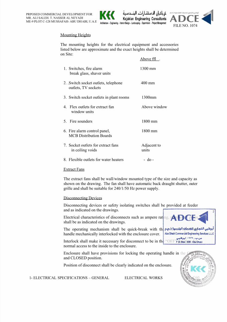
Mounting Heights
The mounting heights for the electrical equipment and accessorieslisted below are approximate and the exact heights shall be determinedon Site:
Above ffl .
1. Switches, fire alarm 1300 mm break glass, shaver units
2. .Switch socket outlets, telephone 400 mmoutlets, TV sockets
3. Switch socket outlets in plant rooms 1300mm
4. Flex outlets for extract fan Above window
window units
5. Fire sounders 1800 mm
6. Fire alarm control panel, 1800 mmMCB Distribution Boards
7. Socket outlets for extract fans Adjacent toin ceiling voids units
8. Flexible outlets for water heaters - do -
Extract Fans
The extract fans shall be wall/window mounted type of the size and capacity asshown on the drawing. The fan shall have automatic back draught shutter, outergrille and shall be suitable for 240/1/50 Hz power supply.
Disconnecting Devices
Disconnecting devices or safety isolating switches shall be provided at feederand as indicated on the drawings.
Electrical characteristics of disconnects such as ampere rating, number of polesshall be as indicated on the drawings.
The operating mechanism shall be quick-break with the external operatinghandle mechanically interlocked with the enclosure cover.
Interlock shall make it necessary for disconnect to be in the “OFF” position fornormal access to the inside to the enclosure.
Enclosure shall have provisions for locking the operating handle in the OPENand CLOSED position.
Position of disconnect shall be clearly indicated on the enclosure.
8/10/2019 11a. Electrical Specifications - General
http://slidepdf.com/reader/full/11a-electrical-specifications-general 33/86
PRPOSED COMMERCIAL DEVELOPMENT FORMR. ALI SALEH. T. NASSER AL NEYADIME-9 PLOT C-128 MUSSAFAH- ABU DHABI, U.A.E
FILE NO. 1074
1- ELECTRICAL SPECIFICATIONS – GENERAL ELECTRICAL WORKS 31 of 60
Disconnects shall be a non-fusible, single throw safety switch in a separateenclosure. Disconnects shall have means of bypassing mechanically interlockdoor and handle. Isolating switches with ratings 15, 30 and 60 Amps shall besimilar to G.E.C. type “Hidutac” or equal. 100 Amps and over isolating switches
shall be similar to G.E.C. “Cromwell” or equal. Disconnects shall be suitable forindoor use where it shall be provided with rubber gasket for weatherproofing.
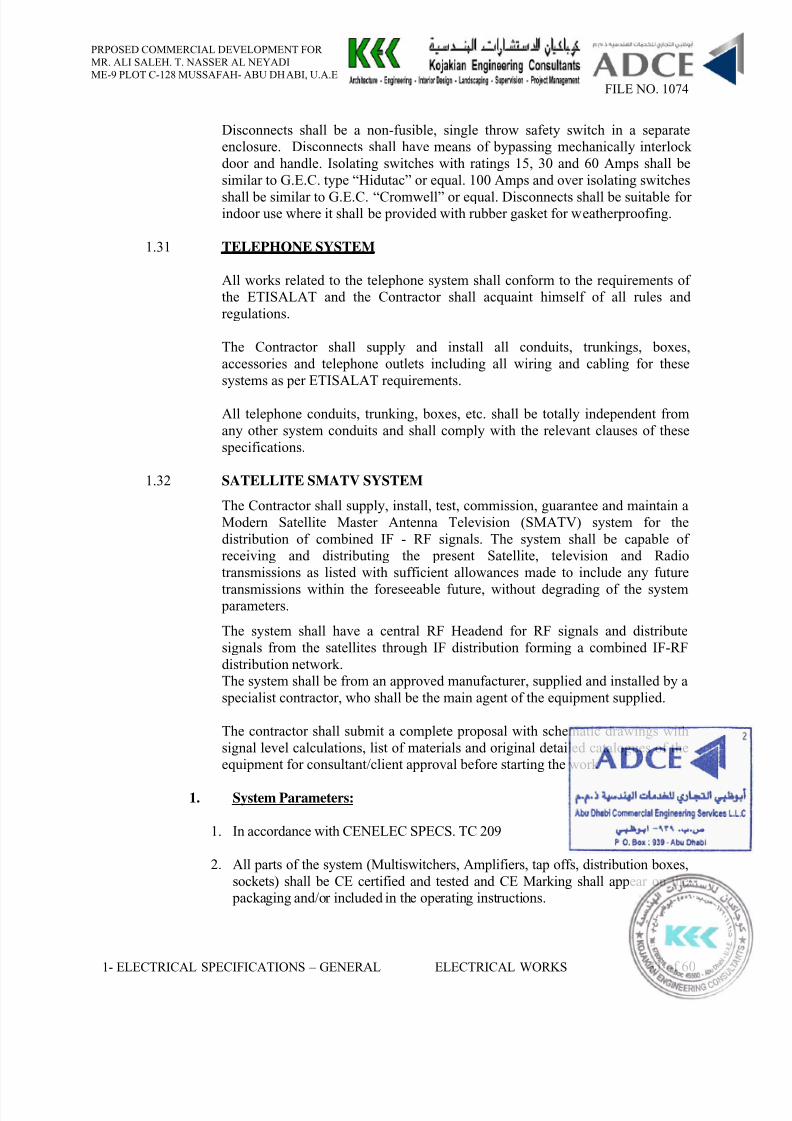
1.31 TELEPHONE SYSTEM
All works related to the telephone system shall conform to the requirements ofthe ETISALAT and the Contractor shall acquaint himself of all rules andregulations.
The Contractor shall supply and install all conduits, trunkings, boxes,accessories and telephone outlets including all wiring and cabling for thesesystems as per ETISALAT requirements.
All telephone conduits, trunking, boxes, etc. shall be totally independent fromany other system conduits and shall comply with the relevant clauses of thesespecifications.
1.32 SATELLITE SMATV SYSTEM
The Contractor shall supply, install, test, commission, guarantee and maintain aModern Satellite Master Antenna Television (SMATV) system for thedistribution of combined IF - RF signals. The system shall be capable ofreceiving and distributing the present Satellite, television and Radiotransmissions as listed with sufficient allowances made to include any future
transmissions within the foreseeable future, without degrading of the system parameters.
The system shall have a central RF Headend for RF signals and distributesignals from the satellites through IF distribution forming a combined IF-RFdistribution network.The system shall be from an approved manufacturer, supplied and installed by aspecialist contractor, who shall be the main agent of the equipment supplied.
The contractor shall submit a complete proposal with schematic drawings withsignal level calculations, list of materials and original detailed catalogues of theequipment for consultant/client approval before starting the work
1. System Parameters:
1. In accordance with CENELEC SPECS. TC 209
2. All parts of the system (Multiswitchers, Amplifiers, tap offs, distribution boxes,sockets) shall be CE certified and tested and CE Marking shall appear on the
packaging and/or included in the operating instructions.
8/10/2019 11a. Electrical Specifications - General
http://slidepdf.com/reader/full/11a-electrical-specifications-general 34/86
PRPOSED COMMERCIAL DEVELOPMENT FORMR. ALI SALEH. T. NASSER AL NEYADIME-9 PLOT C-128 MUSSAFAH- ABU DHABI, U.A.E
FILE NO. 1074
1- ELECTRICAL SPECIFICATIONS – GENERAL ELECTRICAL WORKS 32 of 60
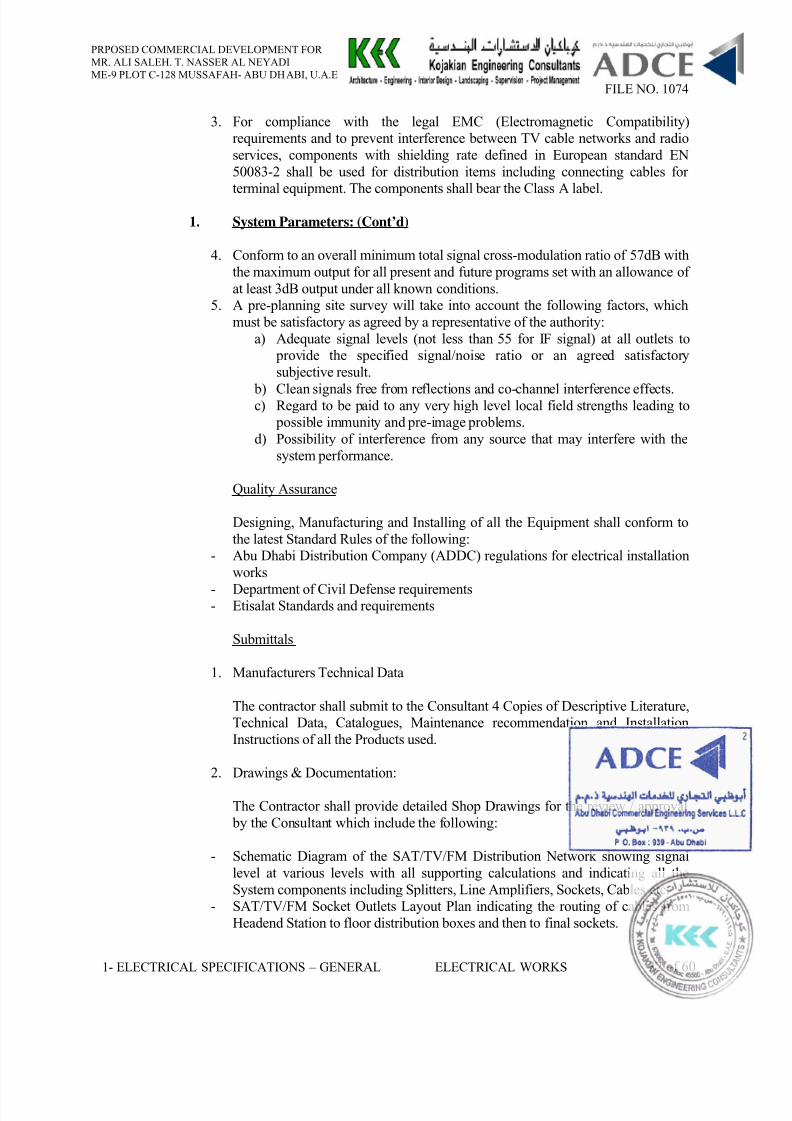
3. For compliance with the legal EMC (Electromagnetic Compatibility)requirements and to prevent interference between TV cable networks and radioservices, components with shielding rate defined in European standard EN50083-2 shall be used for distribution items including connecting cables forterminal equipment. The components shall bear the Class A label.
1. System Parameters: (Cont’d)
4. Conform to an overall minimum total signal cross-modulation ratio of 57dB withthe maximum output for all present and future programs set with an allowance ofat least 3dB output under all known conditions.
5. A pre-planning site survey will take into account the following factors, whichmust be satisfactory as agreed by a representative of the authority:
a) Adequate signal levels (not less than 55 for IF signal) at all outlets to provide the specified signal/noise ratio or an agreed satisfactorysubjective result.
b) Clean signals free from reflections and co-channel interference effects.c) Regard to be paid to any very high level local field strengths leading to possible immunity and pre-image problems.
d) Possibility of interference from any source that may interfere with thesystem performance.
Quality Assurance
Designing, Manufacturing and Installing of all the Equipment shall conform tothe latest Standard Rules of the following:
- Abu Dhabi Distribution Company (ADDC) regulations for electrical installationworks
- Department of Civil Defense requirements- Etisalat Standards and requirements
Submittals
1. Manufacturers Technical Data
The contractor shall submit to the Consultant 4 Copies of Descriptive Literature,Technical Data, Catalogues, Maintenance recommendation and InstallationInstructions of all the Products used.
2. Drawings & Documentation:
The Contractor shall provide detailed Shop Drawings for the review / approval by the Consultant which include the following:
- Schematic Diagram of the SAT/TV/FM Distribution Network showing signallevel at various levels with all supporting calculations and indicating all theSystem components including Splitters, Line Amplifiers, Sockets, Cables etc.
- SAT/TV/FM Socket Outlets Layout Plan indicating the routing of cables fromHeadend Station to floor distribution boxes and then to final sockets.
8/10/2019 11a. Electrical Specifications - General
http://slidepdf.com/reader/full/11a-electrical-specifications-general 35/86
PRPOSED COMMERCIAL DEVELOPMENT FORMR. ALI SALEH. T. NASSER AL NEYADIME-9 PLOT C-128 MUSSAFAH- ABU DHABI, U.A.E
FILE NO. 1074
1- ELECTRICAL SPECIFICATIONS – GENERAL ELECTRICAL WORKS 33 of 60
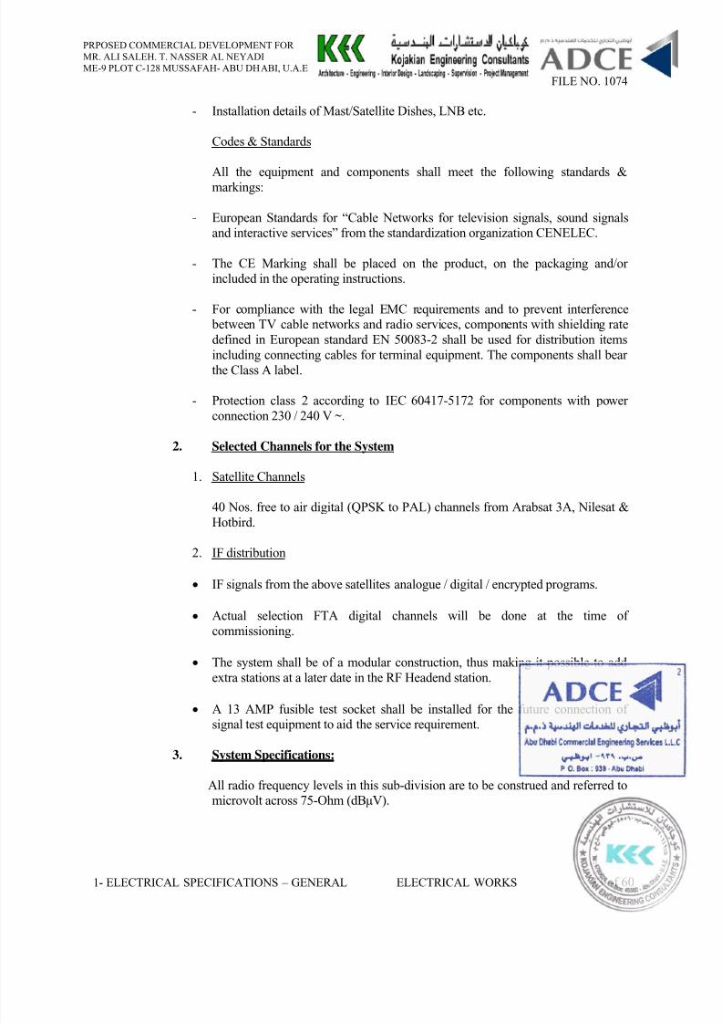
- Installation details of Mast/Satellite Dishes, LNB etc.
Codes & Standards
All the equipment and components shall meet the following standards &markings:
- European Standards for “Cable Networks for television signals, sound signalsand interactive services” from the standardization organization CENELEC.
- The CE Marking shall be placed on the product, on the packaging and/orincluded in the operating instructions.
- For compliance with the legal EMC requirements and to prevent interference between TV cable networks and radio services, components with shielding ratedefined in European standard EN 50083-2 shall be used for distribution items
including connecting cables for terminal equipment. The components shall bearthe Class A label.
- Protection class 2 according to IEC 60417-5172 for components with powerconnection 230 / 240 V ~.
2. Selected Channels for the System
1. Satellite Channels
40 Nos. free to air digital (QPSK to PAL) channels from Arabsat 3A, Nilesat &Hotbird.
2. IF distribution
• IF signals from the above satellites analogue / digital / encrypted programs.
• Actual selection FTA digital channels will be done at the time ofcommissioning.
• The system shall be of a modular construction, thus making it possible to addextra stations at a later date in the RF Headend station.
• A 13 AMP fusible test socket shall be installed for the future connection ofsignal test equipment to aid the service requirement.
3. System Specifications:
All radio frequency levels in this sub-division are to be construed and referred tomicrovolt across 75-Ohm (dBµV).
8/10/2019 11a. Electrical Specifications - General
http://slidepdf.com/reader/full/11a-electrical-specifications-general 36/86
PRPOSED COMMERCIAL DEVELOPMENT FORMR. ALI SALEH. T. NASSER AL NEYADIME-9 PLOT C-128 MUSSAFAH- ABU DHABI, U.A.E
FILE NO. 1074
1- ELECTRICAL SPECIFICATIONS – GENERAL ELECTRICAL WORKS 34 of 60
• One standard radio frequency distribution impedance of 75-Ohm shall be usedwithin the system.
• Return loss shall not be less than 14dB at any point of the system.
• Isolation between any two outlets shall be at least 22dB. Adjacent channelsoperation requires more than 50dB isolation.
• The system shall be such that the short or open circuit at any outlet socket willnot significantly affect signals at other outlets (tap-off system).
• Both IF and RF signals shall be coupled together and fed into the distributionnetwork
• The system shall be capable of continuous operation in an ambient temperatureup to + 50o C.
4. Equipment Specifications:
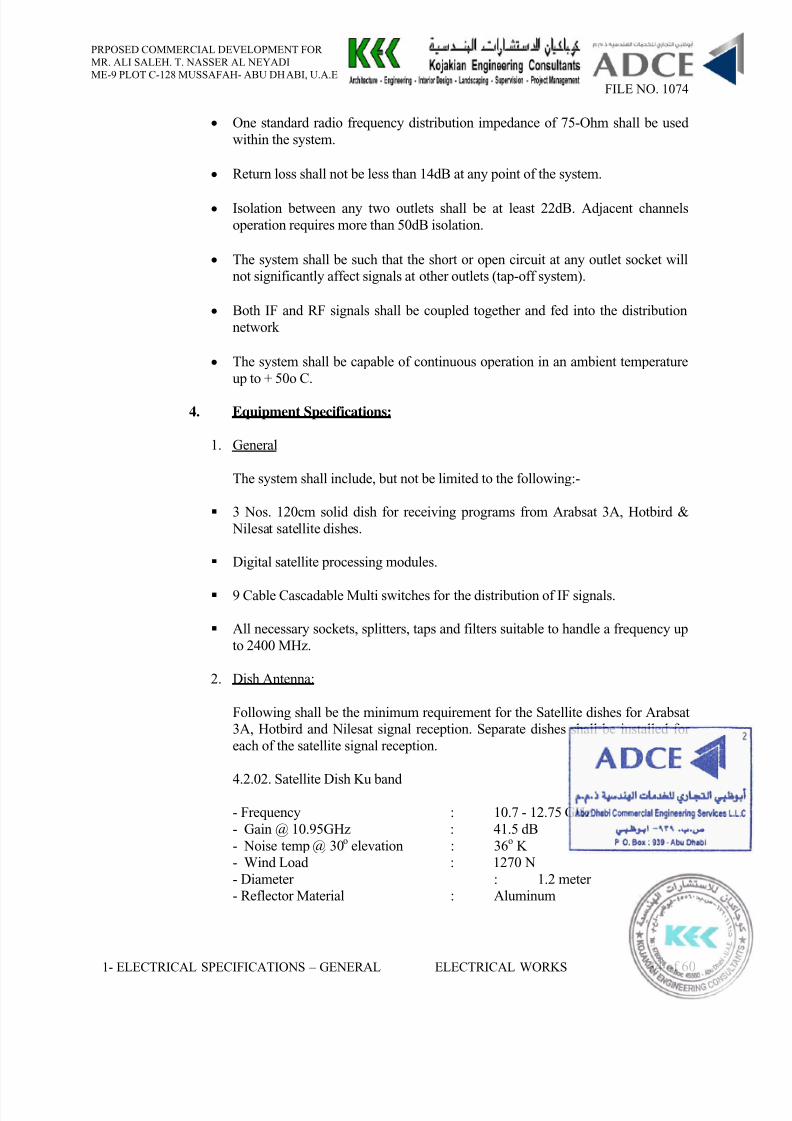
1. General
The system shall include, but not be limited to the following:-
3 Nos. 120cm solid dish for receiving programs from Arabsat 3A, Hotbird & Nilesat satellite dishes.
Digital satellite processing modules.
9 Cable Cascadable Multi switches for the distribution of IF signals.
All necessary sockets, splitters, taps and filters suitable to handle a frequency upto 2400 MHz.
2. Dish Antenna:
Following shall be the minimum requirement for the Satellite dishes for Arabsat3A, Hotbird and Nilesat signal reception. Separate dishes shall be installed foreach of the satellite signal reception.
4.2.02. Satellite Dish Ku band- Frequency : 10.7 - 12.75 GHz- Gain @ 10.95GHz : 41.5 dB- Noise temp @ 30 o elevation : 36 o K- Wind Load : 1270 N- Diameter : 1.2 meter- Reflector Material : Aluminum
8/10/2019 11a. Electrical Specifications - General
http://slidepdf.com/reader/full/11a-electrical-specifications-general 37/86
PRPOSED COMMERCIAL DEVELOPMENT FORMR. ALI SALEH. T. NASSER AL NEYADIME-9 PLOT C-128 MUSSAFAH- ABU DHABI, U.A.E
FILE NO. 1074
1- ELECTRICAL SPECIFICATIONS – GENERAL ELECTRICAL WORKS 35 of 60
3. Head-end Station:
RF System:
• The head-end shall be capable of using adjacent channels without any restriction.
• Satellite processing head-end stations shall consist of basic unit with slots for plugging in the channel processing modules, integrated programmable inputdistribution panel (splitter), power supply unit and microprocessor-based controlunit, all housed in steel cabinet with a lockable door.
• The channel modules must be physically independent; thereby the system willhave built-in modularity enabling easy maintenance and support.
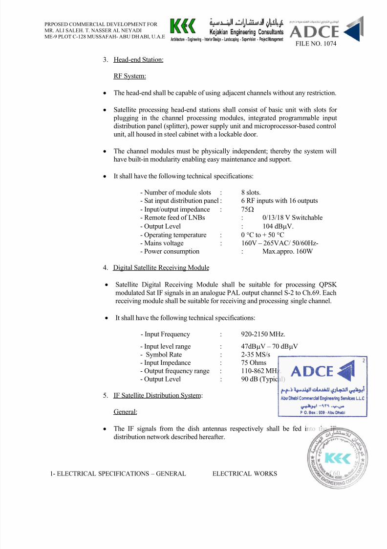
• It shall have the following technical specifications:
- Number of module slots : 8 slots.- Sat input distribution panel : 6 RF inputs with 16 outputs- Input/output impedance : 75 Ω - Remote feed of LNBs : 0/13/18 V Switchable- Output Level : 104 dB µV.- Operating temperature : 0 °C to + 50 °C- Mains voltage : 160V – 265VAC/ 50/60Hz-- Power consumption : Max.appro. 160W
4. Digital Satellite Receiving Module
• Satellite Digital Receiving Module shall be suitable for processing QPSKmodulated Sat IF signals in an analogue PAL output channel S-2 to Ch.69. Eachreceiving module shall be suitable for receiving and processing single channel.
• It shall have the following technical specifications:
- Input Frequency : 920-2150 MHz.
- Input level range : 47dB µV – 70 dB µV- Symbol Rate : 2-35 MS/s- Input Impedance : 75 Ohms- Output frequency range : 110-862 MHz.- Output Level : 90 dB (Typical)
5. IF Satellite Distribution System:
General:
• The IF signals from the dish antennas respectively shall be fed into the IFdistribution network described hereafter.
8/10/2019 11a. Electrical Specifications - General
http://slidepdf.com/reader/full/11a-electrical-specifications-general 38/86
PRPOSED COMMERCIAL DEVELOPMENT FORMR. ALI SALEH. T. NASSER AL NEYADIME-9 PLOT C-128 MUSSAFAH- ABU DHABI, U.A.E
FILE NO. 1074
1- ELECTRICAL SPECIFICATIONS – GENERAL ELECTRICAL WORKS 36 of 60
• The system shall utilize distributing all available IF signals in Arabsat 3A,Hotbird & Nilesat dishes to all the outlets of the building.
• The switching between different polarization planes from the LNB’s shall be
done from the domestic receiver at the outlet sockets. Decoders / Domesticreceivers, etc., if required, shall be provided by the owner / user.
• Outlets shall be connected separately (radial) to switcher, loop connection is not permitted.
• All equipment shall be double shielded and in conformity with VDE or similarstandard.
• The system shall have 100% connectivity for digital signal reception.
6. 9 Cable Cascadable Multiswitcher:
• Switchers shall have 9 cable system, where 8 cables are used for the IFfrequency and 1 cable for RF frequency.
• The switcher shall be cascadable with provision for 4 or 8 subscribers perswitcher.
• Switcher shall have the total frequency range from 47 MHz to 2150MHz.
• Switching possibilities for 8 polarization planes.
• Switcher shall have min. 6 dB through pass attenuation for IF frequency (950-2400MHz).
7. 19” Rack Cabinet
• 19” Steel rack cabinets shall be provided for housing the basic units.
• The rack shall have enough ventilation to allow for dissipation of heat generatedfrom the headed equipments
• The racks shall have required numbers of 230 / 240 V, 13A power sockets to power the basic units / decoders. Unused sockets shall be concealed.
• The racks shall have enough space to provide trunkings, splitters for cabling.
• Cables in the racks shall be wired through trunkings and shall be fastened bycable ties. No loose / unused cables shall be exposed.
• Metallic parts of the cabinets & racks shall be connected to earth rails for potential equalization.
8/10/2019 11a. Electrical Specifications - General
http://slidepdf.com/reader/full/11a-electrical-specifications-general 39/86
PRPOSED COMMERCIAL DEVELOPMENT FORMR. ALI SALEH. T. NASSER AL NEYADIME-9 PLOT C-128 MUSSAFAH- ABU DHABI, U.A.E
FILE NO. 1074
1- ELECTRICAL SPECIFICATIONS – GENERAL ELECTRICAL WORKS 37 of 60
5. Distribution Network:
The distribution elements shall be of die-cast aluminum housing protecting theelectrical components against moisture and corrosion.
All such units shall be located in manholes on dedicated weatherproof boxes protected from ingress of water and other external forces.
The distribution components including amplifiers and splitters/tap-offs along theriser cable shall be of CATV grade.
1. Cables:
Low loss coaxial cable shall be used in order to limit the limit the number ofcascaded amplifiers along the main line.• Cables used within the system shall have air or polyethylene dielectric.
• Cables used for wiring dish antennas shall be ultra violet resistant.
• All the internal cables shall be screened with the following minimumshielding rates:
30 – 470 MHz > 75 dB470 - 1000 MHz > 75 dB1000 - 2050 MHz > 65 dB.
• Maximum loss of the coax-cables shall be as listed:
For external feeders 6 dB/100m at 800 MHz.For internal sockets wiring 18 dB/100m at 800 MHz.For dish antennas wiring 29 dB/100m at 2150 MHz.
• Joints and cable termination shall be adequately sealed against ingress ofmoisture and migration along the cable.
2. Splitters and tap-off boxes:
• Splitters and tap-off boxes used within the system shall ensureapproximately even signal levels at all the outlets in the building. Difference
between the signal levels at the subscribers’ outlets shall not exceed 7 dBµVunder any circumstances.
• All splitters and tap-off boxes used within the system for distributing thesignal to the outlet sockets shall have a minimum frequency range of 5 MHz- 2400 MHz.
• The minimum mutual attenuation between the branched outputs shall be25dB or better.
8/10/2019 11a. Electrical Specifications - General
http://slidepdf.com/reader/full/11a-electrical-specifications-general 40/86
PRPOSED COMMERCIAL DEVELOPMENT FORMR. ALI SALEH. T. NASSER AL NEYADIME-9 PLOT C-128 MUSSAFAH- ABU DHABI, U.A.E
FILE NO. 1074
1- ELECTRICAL SPECIFICATIONS – GENERAL ELECTRICAL WORKS 38 of 60
• Main riser cable shall be securely clamped at each splitter and tap-off position.
3. SAT/TV/FM sockets:
• Sockets shall be broadband type with operating frequency range from 5 MHz- 2400 MHz.
• Sockets shall have SAT / TV / FM triple outlet in rigid metallic structurewith cover similar to the adjacent wiring accessories.
• Sockets shall be wired in radially from the concerned junction box. 75-Ohmend-of-line resistors shall be used for reflection-free terminations.
4. 9 Cable Cascadable Post Amplifiers:
• Cascadable Post Amplifiers shall be used as necessary along the line tocompensate for the signal loss on the co-axial cable. Specifications are asfollows:
- Broad - band range : 47 – 2400 MHz.- Maximum gain : 15/19 dB- Maximum output level : 108 dB µV- Ambient operating temp. : -20 °C to + 50 °C- DiSEqC 2.0, suitable for return path.
• The number of amplifiers shall be made as required for the final wiringlayout.
• Proper arrangements shall be made to dissipate the heat generated duringnormal working of the amplifier.
6. Maintenance :
The system shall be warranted for a period of 12 months after final approval.To maintain the system in a proper working condition a maintenancecontract is strongly recommended.
8/10/2019 11a. Electrical Specifications - General
http://slidepdf.com/reader/full/11a-electrical-specifications-general 41/86
8/10/2019 11a. Electrical Specifications - General
http://slidepdf.com/reader/full/11a-electrical-specifications-general 42/86
PRPOSED COMMERCIAL DEVELOPMENT FORMR. ALI SALEH. T. NASSER AL NEYADIME-9 PLOT C-128 MUSSAFAH- ABU DHABI, U.A.E
FILE NO. 1074
1- ELECTRICAL SPECIFICATIONS – GENERAL ELECTRICAL WORKS 40 of 60
Heat resistant type lamp holders shall be used with flexible cords and enclosedtype lighting fittings regardless of the lamp cap position, i.e. cap-up or capdown.
Lamp holders incorporated in weather proof fittings shall be porcelain or brass.
Fittings installed externally shall be weather proof and insect proof.
Fittings installed in damp locations shall be totally enclosed and shall preventthe ingress of moisture.
Fluorescent fittings shall contain all associated control gear within the fitting.
All metal fittings or metal parts of fittings shall be effectively earthed.
Fittings installed in position subject to vibration shall be of the ant vibrationtype.
Metal used in lighting fitting shall not less than 0.7mm.
Recessed fittings shall be constructed so as to fit into acoustic tile suspendedfalse ceilings, acoustic tile fixed to ceilings or other suspended false ceilings or
plastered ceilings without distorting either the fitting or the ceiling and includingall necessary labour for cutting and making good.
Fittings with hinged diffuser doors shall be provided with spring clips or otherretaining devices to prevent the diffuser from moving.
Shop drawings for non-standard fitting types shall be submitted for approval tothe Engineer.
Detailed catalogue cuts for all fittings or if so required by the Engineer, samplefittings shall be submitted for approval to the Engineer before orders for the
fittings are placed.
Fluorescent Fittings
Wherever a fluorescent lighting fitting is located over an expansion joint, oneend of the fitting shall be free to move or slide.
Recessed fittings shall be constructed so that all components are replaceablewithout removing housing from the ceiling.
Only single and/or two lamp ballast shall be used in any one fitting.
Ballasts shall be completely enclosed inside sheet steel casing, and shall have acorrosion-resistant finish.
Ballasts shall contain a thermosetting type compound not subject to softening orliquefying under any operating conditions or upon ballast failure.
All fluorescent fitting and lamps shall be switch start type according toInternational Specifications.
All ballasts shall be high power factor, compensated to above 0.85 P.F.
8/10/2019 11a. Electrical Specifications - General
http://slidepdf.com/reader/full/11a-electrical-specifications-general 43/86
PRPOSED COMMERCIAL DEVELOPMENT FORMR. ALI SALEH. T. NASSER AL NEYADIME-9 PLOT C-128 MUSSAFAH- ABU DHABI, U.A.E
FILE NO. 1074
1- ELECTRICAL SPECIFICATIONS – GENERAL ELECTRICAL WORKS 41 of 60
Ballasts shall be for operation at the voltages and frequencies indicated underfitting types and /or on the drawings, and under temperature conditions
prevailing in the various locations of the site.
Surface mounted fittings longer than 60cm shall have one additional point of
support besides the outlet box fitting stud when installed individually.Pendant individually mounted fittings 120cm long and smaller shall be providedwith twin stem hangers. Stems shall have ball aligners and provision for aminimum of 2.5cm vertical adjustment.
The various fluorescent fitting types shall be as described in the schedule ofLight Fittings and as shown on Drawings.
Incandescent Fittings
Incandescent fittings shall be equipped with porcelain, medium lamp holder, bayonet type lamp holders fro lamps up to and including 150 watts and righthand screw type lamp holders for lamps 200 watts.
Replacing the lamp shall be possible without having to remove the fitting fromits place.
The various incandescent fittings shall be as described in the schedule oflighting fittings and as shown on drawings.
Lighting fitting for use with tungsten filament lamp shall comply with B.S.4533.
1.34 LAMPS
General Lamps shall be furnished and installed in all lighting fittings furnished underthis contract.
Lamps for permanent installation shall not be placed in the fitting until sodirected by the Engineer, and this shall be accomplished directly before the
building areas are ready for occupancy by the Employer.
Fluorescent TubesLamps shall be of type, wattage and colour rendering index as herein specifiedunless otherwise indicated on drawings.
Fluorescent lamps/tubes shall be diam. 26mm 18W, 36W or 58W for switchstart versions and of lumen output of 1450 lumens for 18 W and 3450 lumensfor 36W and 5400 lumens for 58W the color shall be white and colour temp.3500 Deg. K.
All fluorescent lighting luminaries shall be provided with capacitors to give P.F.in excess of 0.9 logging. Capacitors shall comply with BS 4017 and shall besuitable for operation at temperature up to 85 Deg. C.
8/10/2019 11a. Electrical Specifications - General
http://slidepdf.com/reader/full/11a-electrical-specifications-general 44/86
PRPOSED COMMERCIAL DEVELOPMENT FORMR. ALI SALEH. T. NASSER AL NEYADIME-9 PLOT C-128 MUSSAFAH- ABU DHABI, U.A.E
FILE NO. 1074
1- ELECTRICAL SPECIFICATIONS – GENERAL ELECTRICAL WORKS 42 of 60
1.35 POWER INTAKES
Inclusion of P.S. sum of taking full responsibility for payment of fees, charges, any
sum and unforeseen expenses involved of whatsoever to W.E.D. in bringing permanent electrical power to the project including supply, erection and connectionsof main feeder cables to the project from W.E.D. electricity network systems underW.E.D.’s strict coordination and supervision and be responsible till official handover of the project in good and satisfactory working order.
1.36 VIDEO INTERCOM
The Contractor shall supply, install, test and commission an intercom system asfollows:
a) The intercom panels shall be provided with facility for two way communications
between the panel and the intercom receivers.
The intercom panels shall be elegant design and of anodized aluminumconstruction suitable for recessed mounting.
The push button panel of 35 push buttons shall be installed at the entrance of the building in order to have communications with each and every flat.
Push buttons shall be illuminated from the rear of the panels.
The system operating voltage shall be of extra low voltage (24 volt D.C.).
Name labels should be easily substituted directly on the front plate withoutdismantling the panel.
b) The intercom receivers shall be wall mounted with twisted cord connected to thehandset and shall be installed at the locations as indicated on the following.
c) Conduits should be separate from any other system, shop drawings must besubmitted from Consultant’s approval before starting the work.(Horizontaldistribution will only be allowed).
1.37 CAR ENTRANCE / EXIT BARRIERS
Two automatic car barriers shall be provided to control entrance and exit from thecar parking facility.
Each barrier shall have a span of 3 meters with an aluminum pole in red/whitereflective finish and be complete with stop signs and tip supports.
The barriers shall consist of a cast steel pedestal with fibre glass covers to protectthe drive mechanisms. Raise and lowering shall be by an electric motor driving ascrew shaft mechanism. All necessary control circuitry will be located at the barrier.A hand wind facility and operation by key switch shall be provided at the barrier.
8/10/2019 11a. Electrical Specifications - General
http://slidepdf.com/reader/full/11a-electrical-specifications-general 45/86
8/10/2019 11a. Electrical Specifications - General
http://slidepdf.com/reader/full/11a-electrical-specifications-general 46/86
PRPOSED COMMERCIAL DEVELOPMENT FORMR. ALI SALEH. T. NASSER AL NEYADIME-9 PLOT C-128 MUSSAFAH- ABU DHABI, U.A.E
FILE NO. 1074
1- ELECTRICAL SPECIFICATIONS – GENERAL ELECTRICAL WORKS 44 of 60
c) Torsional Vibrations : BS 5514 Part 5:1984.d) Over speed Protection : BS 5514 Part 6:1992.
Fuel Oils for Non Marine Use : BS 2869.Code of Practice for Safety of Machinery : BS 5304.Radio Frequency Interference suppression : BSEN 55014 and BS 1597.
QUALITY ASSURANCE
Manufacturers
The generating set manufacturer shall preferably be the actual manufacturer ofeither the alternator or the generator and shall be responsible for the assembly. Thegenerator set manufacturer shall have a reliable local representative of good repute,keeping adequate stocks of spare parts and providing efficient after sales services.Tests on Site Tests and inspection procedures shall be formulated to check the performancerequirements and characteristics of the diesel generating sets.
Visual Inspection
All equipment which form part of the diesel generating plant shall be visuallyinspected for damage and checked against the manufacturer catalogues/drawingsand schedule, for the following:-
- Type of generating set- Serial number- Engine details- Alternator, exciter and AVR details- Rated speed- Rated voltage- Number of phases- Rated frequency- Rated KVA at continuous rating- Rated KW at continuous rating- Rated KVA at service rating
- Rated KW at service rating- Ancillary equipment
Preliminary Inspection Check
Preliminary inspection check shall include the following:Alignment of engine/alternator assembly on bed plate.Installation of vibration isolators
Preliminary Running Test
Preliminary running test to check the following:
- Engine start and stop control- Engine oil pressure
8/10/2019 11a. Electrical Specifications - General
http://slidepdf.com/reader/full/11a-electrical-specifications-general 47/86
PRPOSED COMMERCIAL DEVELOPMENT FORMR. ALI SALEH. T. NASSER AL NEYADIME-9 PLOT C-128 MUSSAFAH- ABU DHABI, U.A.E
FILE NO. 1074
1- ELECTRICAL SPECIFICATIONS – GENERAL ELECTRICAL WORKS 45 of 60
- Generator voltage and frequency including phase sequence- Control and protection devices- Leaks in oil, water and exhaust- Excessive vibration- Adjustments of meters and potentiometer related to generated output
parameters.
Tests
The set shall be run continuously for 8 hours test run at rated load followed by110 percent of rated load for a period of one hour.
Every 15 minutes for the first hour and every hour thereafter, the following parameters shall be recorded:-
All electrical output parameters associated with main alternator.
Parameters of charging alternator
Measurements of all engine parameters
Lubricating oil consumption
Cooling air medium flow
Alternator cooling air inlet and outlet temperatures.
Transient Load Switching
Resistive load shall be applied and switched "ON" and "OFF" in STEPS, with thediesel generator running at rated speed and generating rated voltage.
Transient recordings of maximum, minimum and nominal voltage and frequencylevels together with the response times shall be obtained.
Insulation Test
Remove all external wiring between the plant and load bank/ test panels.
Isolate sensitive electronic equipment in alternator and control panel as per
manufacturer's recommendation.Open any neutral earthing links.
Using 1000V megger check the insulation resistance:-
Between the load terminals and plant structure
Between the generator terminals.
Reconnect electronic equipment and neutral earth links.
8/10/2019 11a. Electrical Specifications - General
http://slidepdf.com/reader/full/11a-electrical-specifications-general 48/86
PRPOSED COMMERCIAL DEVELOPMENT FORMR. ALI SALEH. T. NASSER AL NEYADIME-9 PLOT C-128 MUSSAFAH- ABU DHABI, U.A.E
FILE NO. 1074
1- ELECTRICAL SPECIFICATIONS – GENERAL ELECTRICAL WORKS 46 of 60
Functional Test
The operation of interlocks and interconnections with all external equipmentand controls to be connected on site shall be simulated as part of these tests.
Controls, Alarms and ProtectionLocal controls, alarms and shutdown functions associated with the generator setinstallation shall be simulated and demonstrated on site. These tests shallinclude, but not limited to the following:
High coolant temperature test
Over speed test
Low oil pressure test
Over crank test to look after failure to start the engine after five consecutiveattempts.
Product Data
The Contractor shall furnish certified performance data and curves as a part ofhis proposal and a description of his quality control program. The Manufacturershall ascertain that his equipment withstands the starting KW and KVArequirements of the connected load as shown on the Drawings.
The Contractor shall furnish an outline drawing showing principal dimensions,space requirements, and location of connections of the equipment quoted,mainly for starting, cooling, fuel and lubricating system and ventilationrequirements.
The Contractor shall provide a basic tool kit, engine maintenance handbook,spare parts manual and generating set instruction handbook.
The Contractor shall itemize all sight flow indications, temperature sensingdevices, and pressure gauges and indications which will be furnished for localindication of critical items as recommended. If these indicators are standardwith the equipment, it shall be so indicated.The Contractor shall furnish complete information, catalogues, with schematicand detailed diagrams showing all equipment furnished and shall include thecontrol system which will describe the operation, manufacturing and type of allinstruments and control items.
All literature and catalogues shall be in English.SHOP DRAWINGS
The Contractor shall submit for review and acceptance the shop drawings forthe Generator set including all necessary civil work details, such as trenches,concrete bases, etc., generator starting characteristics and manufacturersapproval for the generator's correct selection as to connected load, deratingfactors, etc., wiring diagrams and description of operation.
8/10/2019 11a. Electrical Specifications - General
http://slidepdf.com/reader/full/11a-electrical-specifications-general 49/86
PRPOSED COMMERCIAL DEVELOPMENT FORMR. ALI SALEH. T. NASSER AL NEYADIME-9 PLOT C-128 MUSSAFAH- ABU DHABI, U.A.E
FILE NO. 1074
1- ELECTRICAL SPECIFICATIONS – GENERAL ELECTRICAL WORKS 47 of 60
A copy of shop drawings shall also be sent to the local power authorities forapproval (if needed).
Any modifications to the drawings required by the Engineer or the Local PowerAuthorities to allow the equipment to comply with the codes, standards andspecifications called for herein shall be carried out with no extra cost.
SPARE PARTS
The Contractor shall furnish assurance of availability of recommended spare parts for 2 years and 4 years operation (over and above the one year defectliability period achieving a total of 3 years and 5 years of extended operatingmaintenance) duly priced with his Tender.
The Employer/Engineer reserves the right to accept or reject the same either infull or in part and the contractor shall supply the spare parts as per the final
accepted list, at the time of handing over/ taking over of the Project.Spare parts shall be packed in suitable containers or boxes bearing labels,clearly designating the contents and the particular of equipment for which theyare intended.
The Contractor shall properly store and protect the spare parts until thecompletion of the works and deliver the same to the Client's stores.
WARRANTY
The Contractor shall provide the generator supplier's warranty, warranting thatthe equipment supplied under this specification will be new, of best quality, freefrom defects in design, material, and workmanship and suitable for the specifiedoperating conditions.
Any defects or inadequacies discovered in the equipment during first eighteenmonths from date of delivery and twelve months from the data oferection/installation of equipment, whichever shall expire first, shall be madegood to the satisfaction of the Engineer at the Contractors cost.
Any equipment repaired, replaced or modified shall be subject to a defect freewarranty for a further period of eighteen months from the date of repair,replacement or modification.
PRODUCTS
The equipment shall include but not be limited to the items described in thesespecifications.
The design of the sets shall permit the easy replacement of all items subject towear.
8/10/2019 11a. Electrical Specifications - General
http://slidepdf.com/reader/full/11a-electrical-specifications-general 50/86
PRPOSED COMMERCIAL DEVELOPMENT FORMR. ALI SALEH. T. NASSER AL NEYADIME-9 PLOT C-128 MUSSAFAH- ABU DHABI, U.A.E
FILE NO. 1074
1- ELECTRICAL SPECIFICATIONS – GENERAL ELECTRICAL WORKS 48 of 60
Electrical equipment included in the emergency plant installation shall complywith the relevant clauses of these specifications, unless otherwise indicated.
Engine
The engine shall be diesel, water cooled multi-cylinder unit constructed to BS5514 or ISO 3046. All auxiliaries necessary for operation, including turbocharging and charge air cooling equipment shall be supplied as applicable.The rating of the engine shall be capable of continuous operation as defined inBS 5514. The rating shall include both full and 110% full load for 1 houroperation.
Fuel injection shall be enclosed in-line direct fuel injection type with diaphragmtype fuel lift pumps. Full flow filters with replaceable elements shall be fittedand 24V fuel solenoid shall be provided.
The engine shall be suitable for operation by using fuel oil to BS 2869, DIN 51601 or as recommended by the manufacturer.
The construction of the engine shall facilitate on site maintenance and repairsincluding access to and removal of pistons and connecting rods. The engine andA.C. generator shall be mounted on a common, rigid bed plate supported onspring type anti vibration mountings Means for lifting and moving the set into
position shall be provided.
The engine speed governing system shall be in accordance with BS 5514: part 4to meet the specified values of tolerances. Means for manual adjustments ofengine speed in a range of ±5 percent from the rated speed under all specifiedload conditions shall be provided at the control panel.
An engine over speed protection device shall be provided in accordance withBS 5514: part 6 (ISO 4046/6).The engine lubrication system shall include a large capacity oil sump within the
base plate of the plant. The sump shall be fitted with gear type oil pump withfull flow or filters on the suction and delivery sides. A bypass pressure reliefvalve shall be fitted in the pump delivery. Drip trays shall be fitted to collectany spillage of oil and collecting drained oil.
The lubrication system shall provide a continuous, automatic lubrication to allmoving parts (without any manual intervention). The system shall also includeoil cooler, crankcase breather pipe, manual lubrication facility for priming,sump drain pipe to facilitate oil drainage from the side of the skid and a
dipstick.
The engine coolant shall be circulated by a gear driven centrifugal pumpmounted on the engine. A thermostatically controlled valve shall be provided inthe cooling system to assist rapid heating of water temperature during thestarting of the engine and to provide temperature control when engine isrunning.
8/10/2019 11a. Electrical Specifications - General
http://slidepdf.com/reader/full/11a-electrical-specifications-general 51/86
PRPOSED COMMERCIAL DEVELOPMENT FORMR. ALI SALEH. T. NASSER AL NEYADIME-9 PLOT C-128 MUSSAFAH- ABU DHABI, U.A.E
FILE NO. 1074
1- ELECTRICAL SPECIFICATIONS – GENERAL ELECTRICAL WORKS 49 of 60
An electric immersion heater connected to mains supply shall be fitted tomaintain the engine jacket water temperature to assist quick starting of theengine in cold environment i.e. when the ambient temperature is below 100C.The cooling system shall be closed loop type with set mounted or remoteradiator with integral fan. The radiator fan shall be either directly driven fromthe engine or driven by an electric motor connected to generator electricalsupply. The radiator fan shall be sized to accommodate the pressure drops induct works, louvers and attenuators used in the installation of the emergency
plant.
The cooling system shall include all pipe works, valves, sensors, heaters, etc, to provide satisfactory operation of the diesel generator set under the specifiedloading and ambient conditions.
Care must be taken to see that the surface to which the generator is bolted isaligned in all direction so as to avoid bearing trouble.
Engine mounted radiators shall be connected to radiator exhaust louvers, bymeans of a fire retardant flexible cowling connection as necessary and asapplicable.
Starting System
The engine starting system shall be capable of starting and running the engine atrated cranking speed required for satisfactory ignition.
Engine shall be started by means of battery operated starter motors, mounted onthe engine flywheel housing. Where two starter motors are used for starting,each motor shall be capable of providing the required starting duty at the lowestspecified ambient temperature. The starter motors shall be disengaged from the
engine, when the engine fires or when the starting sequence is de-energized.Starter batteries shall be sealed maintenance free, lead acid type and shall have acapacity required for the above starting operation and to initiate three startingcycles.
Batteries shall be located close to the engine with the leads between the batteriesand the engine duly protected against physical damage.
The batteries shall be easily accessible for maintenance and inspection.Constant voltage type battery charger with monitoring instrumentation shall be
provided for charging the starter batteries. The battery charger shall beautomatically disconnected during the engine starting.
Alternator
The alternator shall be brushless, salient pole and with revolving field and selfregulating alternator. The alternator shall be continuously rated in accordancewith BS 5000: part 99, and shall be capable of providing 110% output for 1hour in any 12 hour duty period.
The generator shall be self cooled by means of an integral shaft mounted fanover the ambient air temperature range specified.

8/10/2019 11a. Electrical Specifications - General
http://slidepdf.com/reader/full/11a-electrical-specifications-general 52/86
PRPOSED COMMERCIAL DEVELOPMENT FORMR. ALI SALEH. T. NASSER AL NEYADIME-9 PLOT C-128 MUSSAFAH- ABU DHABI, U.A.E
FILE NO. 1074
1- ELECTRICAL SPECIFICATIONS – GENERAL ELECTRICAL WORKS 50 of 60
Contractor should take care that the air entering the alternator is not preheated by passing over any hot body such as the engine or its exhaust system.
The alternator shall be of fabricated steel construction with ball and roller
bearing, dynamically balanced and with rotating field salient pole constructionwith heavy damper windings.
The machine shall have an A.C exciter and liberally rated silicon diodeassembly with a built-in excitation system and automatic voltage regulator(AVR). It shall be screen protected, drip proof and with a large terminal box.
Positive voltage build up shall be ensured by the permanent magnets in theexciter field. Constant output voltage control shall be achieved by atransistorized voltage regulator which adjusts the exciter field current tocompensate for all normal variations.
AVR components shall be contained within an enclosure mounted on the
alternator. The enclosure shall be isolated from any vibration forces transmittedfrom the generator. Where diesel generating sets are to operate in parallel, thealternator regulation characteristics shall be designed to facilitate suchoperation, including provision for manual adjustments of characteristics at site.
Insulation to windings of the alternator shall be rated Class H as a minimumstandard. All windings shall be fully impregnated for tropical climates, withhigh quality oil resistant varnish.
Radio interference suppression of the alternator/regulator shall comply with therequirements of BSEN 55014 and BS 1597.
The voltage regulation limits shall be within ± ½ percent under all conditions ofload, power factor and temperature variations from cold to hot.
Voltage drift shall be negligible. Total harmonic content in the line voltagewaveform shall be in the range of 3 percent
Generator Set Mounting
The generator set shall be vibrationally isolated from structure on spring type anti-vibration mountings. There shall be no rigid connections between the generatorset and the structure.
The spring type vibration isolators shall preferably be constructed from suitably
treated and finished steel or steel alloys. They shall be equipped with rubber,neoprene or glass fibre acoustic pads to prevent transmission of high frequencies.
Spring type isolators shall have auxiliary dampers or adjustable snubber typerestraints to prevent excessive movements as the machine speed passes throughresonant frequency of the mounting system.
8/10/2019 11a. Electrical Specifications - General
http://slidepdf.com/reader/full/11a-electrical-specifications-general 53/86
PRPOSED COMMERCIAL DEVELOPMENT FORMR. ALI SALEH. T. NASSER AL NEYADIME-9 PLOT C-128 MUSSAFAH- ABU DHABI, U.A.E
FILE NO. 1074
1- ELECTRICAL SPECIFICATIONS – GENERAL ELECTRICAL WORKS 51 of 60
Coupling SystemThe coupling system shall be of unit construction which forms the engine andgenerator into one unit of exceptional strength and ensures perfect alignment.
The alternator end shield and the engine flywheel housing faces shall be fully
machined with spigots concentric to their shafts. The machined flanges mountedon the alternator shall be connected to the flywheel housing flange by steel bolts.
A flexible rubber block coupling shall be fitted between the engine and alternatorto provide the drive and absorb the transmission of shock loads. The torsionalflexibility shall be designed to match the torsional characteristics of the system to
prevent resonant conditions.
Engine Control Panel and Protective Devices
The engine control panel should be environmentally sealed, solid state micro processor-based modules for engine control, A/C metering and shall include an oil pressure gauge, coolant temperature gauge, battery charge rate ammeter, run/stop/remote selector switch, level gauges for the bulk fuel tank and engine monitoringsystem. The panel shall incorporate all receiving auxiliary contacts forconnections of wiring to a remote start/stop control and a remote annuciator panelas described hereinafter.
Engine monitoring system shall be provided with individual fault lamps toindicate low oil pressure, high coolant temperature, engine over speed and overcrank. All above indicators shall simultaneously shut down the engine. A lamptest switch shall be provided to indicate status of various indicating lamps.
The generating set shall include a complete engine start/stop control to start theengine on closing the relevant contact and to stop the engine on opening thecontact. A cranking limiter shall be provided to open the starting circuit inapproximately 45 to 90 sec if the engine is not started within that time.
Exhaust System
Exhaust system shall include a residential silencer including flexible exhaustfitting, properly sized and installed according to the manufacturer'srecommendation. Silencer shall be mounted so that its weight is not supported bythe engine. Exhaust pipe shall have sufficient size to ensure that exhaust back
pressure does not exceed the maximum limitations specified by the generator setmanufacturer.
The muffler and indoor exhaust piping shall be lagged to maintain a surfacetemperature not to exceed 650C. The insulation shall be installed so that it doesnot interfere with the functioning of the flexible exhaust fittings.
Flexible gastight connection pieces shall be provided in the exhaust pipe line toallow for thermal expansion and to prevent vibration being transmitted from theengine.
A clearance hole shall be allowed where exhaust pipe passes through to avoidoverheating of the surrounding wall.
8/10/2019 11a. Electrical Specifications - General
http://slidepdf.com/reader/full/11a-electrical-specifications-general 54/86
PRPOSED COMMERCIAL DEVELOPMENT FORMR. ALI SALEH. T. NASSER AL NEYADIME-9 PLOT C-128 MUSSAFAH- ABU DHABI, U.A.E
FILE NO. 1074
1- ELECTRICAL SPECIFICATIONS – GENERAL ELECTRICAL WORKS 52 of 60
Base Frame Construction
The combined engine-generator unit shall be bolted to a separate sub-frame whichwill be attached to a main frame through RESILIENT MOUNTINGS so
providing complete protection from engine vibration for the control gear, radiatorand other set mounted components. Mountings under the set will not beconsidered.
The generator shall be mounted on spring type restrained vibration isolatorshaving a static deflection of 50 mm under load conditions.
Air inlet and exhaust attenuators shall be fitted in builders work to reduce thetransmitted noise to specified levels. The generator room shall have appropriateacoustic treatments having a minimum sound transmission loss of 45dB STG.
Base frame shall have four lifting points.
Daily Fuel Tank and Fuel Lift Pump
A daily fuel tank with sufficient fuel capacity for at least 8 hours duty on full loadshall be provided, in a suitable location in the room. A dial type fuel gauge, fuelfilter inlet and outlet connections, drain plug and all feed and return fuel pipe shall
be fitted to the tank complete with hose for filling purposes.
An electrical or manual fuel lift pump shall be supplied and installed near thedaily fuel tank to lift fuel automatically or manually from the bulk storage tank (ifavailable) to the daily storage tank. Necessary float switches to operate lift pumpshall be provided.
Mechanically held transfer switch
The transfer switch unit shall be electrically operated and mechanically held. Theelectrical operator shall be a single-solenoid mechanism, momentarily energizedto minimize power consumption and heat generation.
The switch shall be positively locked and unaffected by voltage variations ormomentary outages so that contact pressure is maintained at a constant value andtemperature rise at the contacts is minimized for maximum reliability andoperating life. The switch shall be mechanically interlocked to ensure only one oftwo possible positions - Normal or Emergency.
All main contacts shall be of silver composition.
ATS utilizing components of moulded case circuit breakers or contactors could beconsidered with price justification and to the approval of Local Power Authoritiesand acceptance of Engineer.

8/10/2019 11a. Electrical Specifications - General
http://slidepdf.com/reader/full/11a-electrical-specifications-general 55/86
8/10/2019 11a. Electrical Specifications - General
http://slidepdf.com/reader/full/11a-electrical-specifications-general 56/86
PRPOSED COMMERCIAL DEVELOPMENT FORMR. ALI SALEH. T. NASSER AL NEYADIME-9 PLOT C-128 MUSSAFAH- ABU DHABI, U.A.E
FILE NO. 1074
1- ELECTRICAL SPECIFICATIONS – GENERAL ELECTRICAL WORKS 54 of 60
The control module shall be completely enclosed with a protective cover and bemounted separately from the transfer switch unit for safety and ease ofmaintenance.
Sensing and control logic shall be provided on plug-in printed circuit boards for
maximum reliability. Interfacing relays shall be industrial control grade plug-intype with dust covers.
All relays shall be identical to minimize the number of unique parts.
The control panel shall meet or exceed the voltage surge withstand capacity inaccordance with IEEE relevant standards, and the impulse withstand voltage testin accordance with the proposed NEMA standard ICS 1-109.
Operation of the Set
The diesel generating set shall be used as "Mains failure" set with automatic startup after a pre-set time during a power failure. Start-up signal for the generatorshall be initiated in the event of;
- Complete main failure in one or all phases of main supply.- Drop or increase in main voltage (adjustable from ± 2.5% to ± 10%).- Unbalance in main phase voltage of ± 2.5%.The generator set shall be capable of supplying various emergency and essentialelectric loads as a single unit.
The generator set shall be suitable for operation under local climatic conditions,as specified.
The emergency generating set shall be designed so that is can take a sudden loadof its rated output and stabilize its speed and voltage in less than 5 seconds. Itshall be capable of carrying full load within 2 minutes after having been firstloaded.
Should the engine fail to start in 25 seconds following a power interruption, theemergency plant shall come to rest for 10 second. Two further attempts shall beautomatically performed with intermediate period of rest.
It shall be possible to operate the generator set manually for testing and normaloperation purposes.After the restoration of normal power to above 90% of its rated value for an
adjustable period of time (setting 2 to 60 minutes) the change over switch shallautomatically revert to its normal operation. The emergency plant shall stop onlyafter a cool down time (setting for 1 to 30 minutes).
Control modules shall be single phase for single phase power sources and three phases for three phase power sources. A selector switch shall be included in thethree phase control modules to enable temporary operation on single phase powersources.
8/10/2019 11a. Electrical Specifications - General
http://slidepdf.com/reader/full/11a-electrical-specifications-general 57/86
PRPOSED COMMERCIAL DEVELOPMENT FORMR. ALI SALEH. T. NASSER AL NEYADIME-9 PLOT C-128 MUSSAFAH- ABU DHABI, U.A.E
FILE NO. 1074
1- ELECTRICAL SPECIFICATIONS – GENERAL ELECTRICAL WORKS 55 of 60
The voltage of each phase of the normal source shall be monitored, with pick-upadjustable from 85 to 100% and drop out adjustable from 75 to 98% of pick-upsetting both in increments of 1%, and shall be fully field-adjustable without theuse of any tools, meters or power supplies. Repetitive accuracy of settings shall
be ± 2% or better over an operating temperature range of -20o to +70oC. Settingsat factory shall be 90% for pick-up and 85% for dropout.
Single phase voltage sensing of the emergency source shall be provided with a pick-up adjustable from 85 to 100% and frequency sensing with pick-upadjustable from 90 to 100%. Both voltage and frequency settings shall be fullyfield adjustable in 1% steps increment. Repetitive accuracy of settings shall beminimum + 2% at an operating temperature range of -20oC to + 70oC.
The control module shall include four time delays that are fully field adjustable:
Time delay adjustable from 0 to 6 seconds to override momentary normal sourceoutages to delay all transfer switch and engine starting signals. Transfer to
emergency time delay adjustable from 0 to 5 minutes.Retransfer to normal time delay adjustable from 0 to 30 minutes. This time delayis automatically by passed if emergency source fails and normal source isacceptable.
Unloaded running time delay for emergency engine generator cools down,adjustable from 0 to 60 minutes.
10 AMPs rated contacts, 32 V DC shall be provided for low voltage engine startsignal when the normal source fails. The start signal shall prevent dry cranking ofthe generator by requiring the generator to reach proper output, and to run fromthe duration of the cool down setting regardless of whether the normal sources
restores before the load is transferred.A momentary type test switch shall provide to simulate a normal source failure.
Terminals for remote contacts operation shall be provided.
A visual position indicator shall be provided to indicate by- pass isolation switch position.
Pilot lights shall indicate availability of power sources and automatic transferswitch position.
An instruction plate shall be provided.Auxiliary contracts shall be provided to signal the actual availability of the normaland emergency sources.
Operators manual shall be furnished with each ATS providing installation andoperating instructions.
The Automatic transfer switch shall comply with UL 1008, NFPA70, NFPA99, NFPA110, IEEE, NEMA and IES relevant standards.
8/10/2019 11a. Electrical Specifications - General
http://slidepdf.com/reader/full/11a-electrical-specifications-general 58/86
PRPOSED COMMERCIAL DEVELOPMENT FORMR. ALI SALEH. T. NASSER AL NEYADIME-9 PLOT C-128 MUSSAFAH- ABU DHABI, U.A.E
FILE NO. 1074
1- ELECTRICAL SPECIFICATIONS – GENERAL ELECTRICAL WORKS 56 of 60
Proper factory test with a test certificate of all parameters of the ATS shall be provided prior to installation.
Finish
All sheet steel used shall be zinc coated for rust protection. Sets shall be paintedwith an etching primer and finished with a high gloss grey paint grade 632 to BS381C, or approved equal.
Alarm Annunciator
Annunciator shall be constructed of sturdy sheet steel enclosure having aremovable front panel and adapter ring.
Annunciator shall be a flush mounting unit. The face of the front panel shallincorporate nine lamps, an audible alarm, a toggle switch marked NORMAL andOFF, and a lamp test push-button switch. The printed circuits internal wiring,
terminal block and battery voltage sensors shall be accessible on removing thefront panel.
The following indications, alarms and lockouts shall be included in the control panel:
Indication Lamp, identification Label, Color, Function
- Mains available R.Y.B Indication- Mains on load Green Indication- Set on stand-by Green Indication- Set on manual Amber warning lamp- Mains failed Red Alarm- Set on load Green Indication- Control switch off Red Alarm- Control switch manual Amber warning /Alarm- Set failed to start Red (Flashing)
Alarm/LockoutGenerator overload relay tripped Red Alarm
- Earth fault relay tripped Red Alarm/Lockout- Circuit breaker open Green Indication- Circuit breaker closed Amber Indication- Circuit breaker tripped Red Indication- High engine temperature Amber warning /Light
Additionally following indication lamp shall be provided to show the status of thegenerator set:
Low oil pressureExcessive coolant temperatureEngine over speedLow fuel supplyLow battery voltage
8/10/2019 11a. Electrical Specifications - General
http://slidepdf.com/reader/full/11a-electrical-specifications-general 59/86
PRPOSED COMMERCIAL DEVELOPMENT FORMR. ALI SALEH. T. NASSER AL NEYADIME-9 PLOT C-128 MUSSAFAH- ABU DHABI, U.A.E
FILE NO. 1074
1- ELECTRICAL SPECIFICATIONS – GENERAL ELECTRICAL WORKS 57 of 60
High battery voltageLow jacket water temperature
Annunciator panel shall operate on DC source taken from the batteries of thegenerator it-self.
The indication lamps shall be twin long life LED type.
In all cases, the re-set of lock out shall be done manually. Lamps shall continueto light until the fault is reset.
Lamp test facility shall be provided to check the status of lamps.
Alarm and lockout system shall not operate during normal shut down operation. SCHEDULE OF REQUIREMENTS
SCHEDULE NO. 1Generator set reference: ..............Type of generating set operation: Prime/standbyLoad data
Nominal voltage Nominal currentFrequencySteady state voltage toleranceMaximum load step changeDuration of load step changeVoltage dip
Frequency toleranceLocation of siteAltitudeAir temperature rangeRelative humidity rangeConcrete foundation: isolated/non-isolated.
SCHEDULE NO. 2
Engine and Alternator Details (to be filled by the Sub-Contractor).Generator set reference :Manufacturer and type No. :Rated power/efficiency :Rated voltage :Rated current :Rated frequency :Power factor :Overload capacity :Method of engine starting :Type of cooling :Type of governor and Class (BS 5514: Part 4) :
8/10/2019 11a. Electrical Specifications - General
http://slidepdf.com/reader/full/11a-electrical-specifications-general 60/86
PRPOSED COMMERCIAL DEVELOPMENT FORMR. ALI SALEH. T. NASSER AL NEYADIME-9 PLOT C-128 MUSSAFAH- ABU DHABI, U.A.E
FILE NO. 1074
1- ELECTRICAL SPECIFICATIONS – GENERAL ELECTRICAL WORKS 58 of 60
Type of fuel :Fuel consumption at full load :Exhaust system details :Sound annunciator details :Alternator Details :- Degree of Protection :- Method of cooling :- Insulation class :- Maximum temperature rise :- Rated ambient temperature :- Method of excitation :- Bearing Types :
Safety
All external electrical and mechanical connections shall be with flexible end
connections to allow free movements of the diesel generator set on resilientmountings. All exposed mounting parts shall be fully guarded to prevent contact by personnel. Guards shall comply with BS 5304, and shall be removable formaintenance purposes.
A permanently fixed warning notice with 6mm white lettering on a red background shall be fixed to the set in a prominent position.
The warning shall be as follows:
"THE GENERATING SET IS UNDER AUTOMATIC CONTROL AND MAYSTART AT ANY TIME WITHOUT WARNING"
EXECUTION
Generator Earthing
Generator shall have its neutral solidly connected to the system earth through thetransfer switch. No local system earthing means shall be used as it would create amultiple earthing of the neutral which may cause stray currents. Alternatively theSub-Sub-Contractor may use a local earthing of the neutral if he uses anoverlapping neutral transfer contact in the automatic transfer switch.
Generator frame shall be connected to the equipment earthing system through aseparate equipment earth conductor. Additionally, a local earth electrode might berequired if generator is appreciably remote from the main electrical room. Neutraland frame of generator shall not be bonded except in the case of local neutralearthing as mentioned above.
The generator set earthing shall be separate from the general earthing of the building.
8/10/2019 11a. Electrical Specifications - General
http://slidepdf.com/reader/full/11a-electrical-specifications-general 61/86
PRPOSED COMMERCIAL DEVELOPMENT FORMR. ALI SALEH. T. NASSER AL NEYADIME-9 PLOT C-128 MUSSAFAH- ABU DHABI, U.A.E
FILE NO. 1074
1- ELECTRICAL SPECIFICATIONS – GENERAL ELECTRICAL WORKS 59 of 60
1.39 ELECTRICAL MOTORS & MOTOR STARTERS
Electrical Motors
All motors shall be constructed and type tested in compliance with relevant
sections of BS4999 and BS5000 these shall be of totally enclosed fan cooled(TEFC) type either with foot mounting or flange mounting suitable for itsapplication. Unless otherwise specified, motors shall be designed for continuousrunning duty type SI for operation during three years without maintenance.Motors shall be suitable for direct –on-line starting. They shall be of such size asto drive adequately their associated equipment under the range of operatingconditions, without overloading. Windings shall be insulated with Class Finsulation material to BS 2757, and temperature rise of winding shall be Class B(i.e. maximum of 80 Deg. C. as measured by resistance method).
All the motors shall be provided with a substantial earthing terminal tapped intothe frame or clamping device located on the cable and box side of the motor.
When air inlets are protected by a screen, such a screen shall be of corrosionresistant material.
Terminal connections shall be constructed in such a way that direct contact between screws, bolts or nuts and the conductor is avoided.
The terminals shall be alphabetically or numerically marked in such a way that thecyclic sequence in time of the supply corresponds to the sequence of terminalmarkings, the direction of rotation is clockwise when facing the driving end.
The terminal box shall be of sturdy construction with ample space for connectingcables. An earthing bolt of adequate size shall be provided inside the terminal boxfor connecting to the cable earthing. This will be in addition to the earthing bolt
provided in the motor enclosure. The terminal box shall be adequatelyweatherproofed with a suitable non-sticking reusable non hygroscopic gasketmaterial.
These terminal boxes also shall be provided with suitable cable sealing end boxes or cable glands. The rating plate shall be made of a corrosion-resistantmetallic material, fixed to a non removable part of the frame, and shall bemarked with the appropriate items in accordance with IEC 34-1, whereby thevalue given shall be those actually measure.
In addition to these items the following information shall be indicated:
a) Type of enclosure in accordance with IEC 34-5 (IP classification). b) Locked rotor torque in of rated torque.
Locked motor current in of rated current.c) Allowable running-up time in seconds (ART) bearing type, size, fit regreasing
period and type of grease.d) Net weight
e) Purchase order number.
8/10/2019 11a. Electrical Specifications - General
http://slidepdf.com/reader/full/11a-electrical-specifications-general 62/86
PRPOSED COMMERCIAL DEVELOPMENT FORMR. ALI SALEH. T. NASSER AL NEYADIME-9 PLOT C-128 MUSSAFAH- ABU DHABI, U.A.E
FILE NO. 1074
1- ELECTRICAL SPECIFICATIONS – GENERAL ELECTRICAL WORKS 60 of 60
The frame shall be painted in accordance with manufacturer’s standards.However, the painting shall at least consist of one coat of primer and two coatsof oil-resistant finishing paint.
Motor StartersAll the motors shall be provided with heavy duty contractor type motor starters,generally complying with the following:
2.5 HP and below direct-on-line starting.2.5 HP – 50 HP Star-Delta starting.
The Contractors shall be 4-pole units designed for use on AC. The magnet andcontact movements shall be horizontal. The contacts shall be double-break, butttype and each moving contact shall be individually spring-loaded. All fixed andmoving contacts shall be of silver-cadmium oxide.
The Contractor coils shall be of the continuous –rated type. These coils shall bewound on moulded formers and shall be vacuum imoregnated. TheseContractors shall be type tested to AC3 rating. Thermal overload relays shall be
provided as an integral part for all the starters.
These shall be factory calibrated, ambient temperature compensated and sealed,each provided with Auto/Manual reset control. These relays shall provideaccurate and consistent protection on 3 phase overloads and accelerated trippingunder single-phase conditions. Trip alarm contacts shall be incorporated in theserelays as an integral part.
Each Contractor shall be provided with an adequate number of auxiliaryswitches of N/O and N/C types. All Star-Delta starters shall be provided withmechanical and electrical interlocks for Star and Delta Contractor assemblies to
prevent accidental short-circuiting.
Adjustable time delay devices shall be incorporated for all Star Delta Starters.
All the starters shall be manufactured and type-tested in accordance withBS4941 part1, BS 4941 part 2, IEC 292-1 and IEC 292-2, as relevant to the typeof starter.
8/10/2019 11a. Electrical Specifications - General
http://slidepdf.com/reader/full/11a-electrical-specifications-general 63/86
PRPOSED COMMERCIAL DEVELOPMENT FORMR. ALI SALEH. T. NASSER AL NEYADIME-9 PLOT C-128 MUSSAFAH- ABU DHABI, U.A.E
FILE NO. 1074
1- ELECTRICAL SPECIFICATIONS – GENERAL EARTHING SYSTEM 1 of 7
EARTHING SYSTEM
GENERAL SPECIFICATION
CONTENTS
1.0 GENERAL
1.1 REFERENCE1.2 DESCRIPTION OF WORK1.3 QUALITY CONTROL ASSURANCE1.4 CODES AND STANDARDS
1.5 SUBMITTALS
2.0 PRODUCTS
2.1 EARTHING SYSTEM MATERIALS2.2 TECHNICAL REQUIREMENTS
3.0 EXECUTION
3.1 INSTALLATION3.2 TESTING AND COMMISSIONING
8/10/2019 11a. Electrical Specifications - General
http://slidepdf.com/reader/full/11a-electrical-specifications-general 64/86
PRPOSED COMMERCIAL DEVELOPMENT FORMR. ALI SALEH. T. NASSER AL NEYADIME-9 PLOT C-128 MUSSAFAH- ABU DHABI, U.A.E
FILE NO. 1074
1- ELECTRICAL SPECIFICATIONS – GENERAL EARTHING SYSTEM 2 of 7
1.0 GENERAL
1.1 REFERENCE
Conform to General Requirements for Electrical Services of Division 16.
1.2 DESCRIPTION OF WORK
Supply, installation, testing and commissioning of complete earthing system as specifiedhereafter and as indicated in the related system drawings. Scope of work shall include butnot limited to the following for each building:
a) Main earthing system of the building consists of ECC conductors, earth bars,earth pits, all related accessories including bonding and terminations.
b) Earthed equipontential bonding of all exposed and extraneous conductive parts.
c) Earthing system for the telephone and data communication system including ECCconductors, earth bars, earth pits, all related accessories including bonding andterminations.
d) Clean earth arrangement for the power distribution and power outlets feedingcomputer terminals and related equipment.
e) Substation earthing system including transformer neutral earthing.
f) Earthing system for Generator sets.
g) Earthing system for the external electrical services including Pump rooms ofwater features, external lighting poles, etc.
8/10/2019 11a. Electrical Specifications - General
http://slidepdf.com/reader/full/11a-electrical-specifications-general 65/86
PRPOSED COMMERCIAL DEVELOPMENT FORMR. ALI SALEH. T. NASSER AL NEYADIME-9 PLOT C-128 MUSSAFAH- ABU DHABI, U.A.E
FILE NO. 1074
1- ELECTRICAL SPECIFICATIONS – GENERAL EARTHING SYSTEM 3 of 7
1.3 QUALITY CONTROL / ASSURANCE
Design, manufacture, testing and method of installation of all apparatus and materialsfurnished under requirements of these specifications shall conform to latest publicationsor standard rules of the following:
a) Abu Dhabi Distribution Company (ADDC) regulations for electrical installationworks and Department of Civil Defense requirements.
b) Etisalat Standards and requirements
c) Regulations for the Electrical Equipment of Buildings (IEE), (BS) London.
d) British Standards.
The Quality Control / Assurance duties shall be performed by the Contractor. The systemof Quality Control / Assurance / Assurance verification shall be in accordance with ISO9000 standards of quality assurance.
1.4 CODES AND STANDARDS
The following codes and standards to the extent specified herein, form a part of thisspecification. When and edition date is not indicated for a Code or Standard the latestedition enforce at the time of proposal submitted shall apply.
CP 1013 BS Code of Practice – EarthingBS 7671 BS Requirement for Electrical InstallationBS 7430 BS for earthing system, material and testing.BS 2784 & BS 970 BS for earthing material, solid copper rods and accessories.ADDC Abu Dhabi Distribution Company
1.5 SUBMITTALS
The CONTRACTOR shall submit the following drawings and documents related witheach electrical system for CONSULTANT / PROJECT MANAGER approval:
a) Original catalogues for various proposed components. b) Schedule of Accessories and Fittings.c) Test Certificates.
8/10/2019 11a. Electrical Specifications - General
http://slidepdf.com/reader/full/11a-electrical-specifications-general 66/86
PRPOSED COMMERCIAL DEVELOPMENT FORMR. ALI SALEH. T. NASSER AL NEYADIME-9 PLOT C-128 MUSSAFAH- ABU DHABI, U.A.E
FILE NO. 1074
1- ELECTRICAL SPECIFICATIONS – GENERAL EARTHING SYSTEM 4 of 7
2.0 PRODUCTS
2.1 EARTHING SYSTEM MATERIALS
Earthing system materials shall include the following:
a) Bonding Conductors b) Earth continuity conductorsc) 150mm2 earth bar risers.d) 150mm2 copper tape, earth pits & wells.e) Earth grid bar.f) Thermal welding kits and accessories.g) Lugs, terminals, clamps, accessories etc.h) Any other material indicated on the drawing or required by BS7430, BS7671.i) Copper earth rods.
2.2 TECHNICAL REQUIREMENTS
2.2.1. The complete installation covered by this specification shall be efficiently bonded backto the main switchboards through the metal sheating of cables, the steel conduit, thetrunking system and earth wires/bars.
2.2.2. The nominal cross-sectional area of all earth continuity conductors shall be inaccordance with IEE regulations and to ADDC approval. The earth wire size shall beequal to the phase wire if the conductor cross section is less than 16 square millimeter
and shall have half of the phase conductor size for sizes higher than 16 squaremillimeter.
2.2.3. A 150mm2 earth bar riser shall be installed in each electrical room and shall beconnected to a 6mm x 50mm x length (as shown on the plan). Earth bar with enoughnumber of ways and mounted on high impact uPVC channel with disconnecting link
provided in each electrical room and shall be connected to the individual switchboardearth bar through a cable sized in accordance to IEE Regulations and to theequipotential bonding conductor connecting metal conduits, trunking systems, metalframes, enclosures, cable sheaths, A/C duct work, pipe riser etc.
A ‘clean’ earth 150mm2 copper bar riser shall as well as be installed and shall beconnected to ‘clean’ earth bar similar to the earth bar specified above and installed ineach electrical room. This bar shall provide clean earth to all the clean earth poweroutlets.
2.2.4. The above mentioned earth bars riser shall be connected through 150mm2 copper tapeto separate earth pits with removable concrete cover.
8/10/2019 11a. Electrical Specifications - General
http://slidepdf.com/reader/full/11a-electrical-specifications-general 67/86
PRPOSED COMMERCIAL DEVELOPMENT FORMR. ALI SALEH. T. NASSER AL NEYADIME-9 PLOT C-128 MUSSAFAH- ABU DHABI, U.A.E
FILE NO. 1074
1- ELECTRICAL SPECIFICATIONS – GENERAL EARTHING SYSTEM 5 of 7
2.2.5. All such earth pits and wells shall be connected together and with the lightning protection system pit in order to create and earth grid extending throughout the site inthe form of an earth ring with branches connected to the equipment and building to beearthed. The earth grid shall comprise copper earthing cable with green/yellow PVCsheathing.
2.2.6. All switchboards, metal conduit and trunking systems, metal frames, enclosures,lighting fittings and cables sheaths shall be bonded together and connected through16mm2 PVC cable to the earth bar of the appropriate switchboard. Similarly all earth
pins and metallic plates of socket outlets, switches, accessories and enclosures shall be bonded to earth with earth continuity conductors. Each individual earth path shall beelectrically continuous throughout its length from the farthest point of the associated
part of the system back to the main earth.2.2.7. Where separate pieces of apparatus connected to different phase are, of necessity
erected or positioned less than two meters apart, and equipotential bonding conductoror single core 70mm2 PVC sheathed shall be installed between such pieces ofapparatus.
2.2.8. In the substations, earth grid bus shall be provided and shall connect all the electricalequipment to the earth pit.
2.2.9. The star point of the transformers shall be solidly earthed through separate earth welland to ADDC approval.
2.2.10. All earthing cables shall be installed in accordance with the relevant requirementscalled for in the cables section of this specification.
2.2.11. All wires and cables shall be protected against mechanical stress and corrosion. All joints between wires and earthing metal work shall be mechanically sound and bimetallic connector shall be used wherever necessary.
2.2.12. All bonding leads shall be carried out using threaded fittings, lockout/hardware,thermite welding or any other method approved by the Consultant/ Project Manager.
2.2. 13. A test connection link shall be provided for testing purpose.
a) Earthwell
Earthwells shall be provided if required only to provide the earth grid at the chilleryard and at substations. Earth well with 100 mm diameter GS pipe shall be driven
upto the water table. An earth bar shall be welded to the top of the earth well for branch connections. The well shall be protected by a concrete housing with MS orconcrete cover of 250mm x 250mm x 10mm at grade level.
8/10/2019 11a. Electrical Specifications - General
http://slidepdf.com/reader/full/11a-electrical-specifications-general 68/86
PRPOSED COMMERCIAL DEVELOPMENT FORMR. ALI SALEH. T. NASSER AL NEYADIME-9 PLOT C-128 MUSSAFAH- ABU DHABI, U.A.E
FILE NO. 1074
1- ELECTRICAL SPECIFICATIONS – GENERAL EARTHING SYSTEM 6 of 7
b) Earth pits
20mm diameter copper earth rod shall be driven to a minimum depth of 6M and anearth bar shall be provided to the top of the earth pit for branch connections. Earth
pit shall be protected by concrete housing and MS or concrete cover at grade level.Bentonite shall be provided in the pit around the earth rod.
The number / depth of pits shall be sufficient to make the system resistance lessthan one ohm.
Earth cables shall be buried at a minimum depth of 500mm after coordinating thesame with other services.
3.0 EXECUTION
3.1 INSTALLATION
3.1.1 The whole of the earthing and bonding shall be installed and tested in accordance withthe requirements of the IEE Wiring Regulations, Local Authority requirements and thisspecification.
3.1.2 All enclosures, equipment, exposed conductive parts, extraneous conductive parts,metallic trunking, metallic conduits, metallic cable trays and other metalwork, otherthan any live part, forming protection to or part of the electrical installation, includingapparatus and appliances, shall be effectively bonded to earth.
3.1.3 Provide an earth bar 650mm long and 90mm width as minimum on the wall of eachelectrical, mechanical and plant rooms and connect to the enclosure and ground busesof all equipment in the room.
3.1.4 Remove non-conductive coatings from threads or other contact surfaces to ensure goodelectrical continuity.
3.1.5 Protect all exposed grounding conductors from mechanical damage.
3.1.6 Soldered joints are not permitted.
3.2 TESTING AND COMMISSIONING
3.2.1 General
a) The complete installation shall be tested and inspected to ensure that it complieswith the requirements of this Specification, the IEE Wiring Regulations, BritishStandards and the Local Authorities. The tests shall be carried out in accordancewith the IEE Wiring Regulations and to the satisfaction of theCONSULTANT/PROJECT MANAGER.
8/10/2019 11a. Electrical Specifications - General
http://slidepdf.com/reader/full/11a-electrical-specifications-general 69/86
PRPOSED COMMERCIAL DEVELOPMENT FORMR. ALI SALEH. T. NASSER AL NEYADIME-9 PLOT C-128 MUSSAFAH- ABU DHABI, U.A.E
FILE NO. 1074
1- ELECTRICAL SPECIFICATIONS – GENERAL EARTHING SYSTEM 7 of 7
b) The inspection and tests shall be carried out in the same sequence as set out inthe IEE Wiring Regulations, Local Authorities and in such time as to allow anyremedial work to be completed prior to Practical Completion of the project.
c) The earth resistance shall not exceed 1 ohm.
d) All the portal frames shall be ring earthed 50mm size and all the joint to be35mm size and to be connected to the main earth pit.
e) Tests shall be carried out strictly in accordance with a programme to be agreedwith THE CONSULTANT/PROJECT MANAGER prior to commencement ofsuch tests. Facilities shall be provided for witnessing of such tests.
f) All instruments necessary for inspection and testing shall be supplied and shall be properly calibrated and operated by personnel skilled in their use.
g) Allowance shall be made for disconnection or similar operations to satisfy therequirements for testing, etc., and the reinstatement of the installation.
8/10/2019 11a. Electrical Specifications - General
http://slidepdf.com/reader/full/11a-electrical-specifications-general 70/86
PRPOSED COMMERCIAL DEVELOPMENT FORMR. ALI SALEH. T. NASSER AL NEYADIME-9 PLOT C-128 MUSSAFAH- ABU DHABI, U.A.E
FILE NO. 1074
1- ELECTRICAL SPECIFICATIONS – GENERAL LIGHTNING PROTECTION SYSTEM 1 of 9
LIGHTNING PROTECTION SYSTEM
GENERAL SPECIFICATION
8/10/2019 11a. Electrical Specifications - General
http://slidepdf.com/reader/full/11a-electrical-specifications-general 71/86
PRPOSED COMMERCIAL DEVELOPMENT FORMR. ALI SALEH. T. NASSER AL NEYADIME-9 PLOT C-128 MUSSAFAH- ABU DHABI, U.A.E
FILE NO. 1074
1- ELECTRICAL SPECIFICATIONS – GENERAL LIGHTNING PROTECTION SYSTEM 2 of 9
LIGHTNING PROTECTION SYSTEM
GENERAL SPECIFICATION
CONTENTS
1.0 GENERAL
2.0 MATERIALS
3.0 BONDING
4.0 TESTING
5.0 RECORDS
6.0 MAINTENANCE

8/10/2019 11a. Electrical Specifications - General
http://slidepdf.com/reader/full/11a-electrical-specifications-general 72/86
PRPOSED COMMERCIAL DEVELOPMENT FORMR. ALI SALEH. T. NASSER AL NEYADIME-9 PLOT C-128 MUSSAFAH- ABU DHABI, U.A.E
FILE NO. 1074
1- ELECTRICAL SPECIFICATIONS – GENERAL LIGHTNING PROTECTION SYSTEM 3 of 9
1.0 GENERAL
The Specialist Lightning Protection Installer shall provide a lightning protection systemcompletely in accordance with
BSEN 62305 (I – IV): 2006CENELEC standard for Lightning Protection
BS EN 50164-1: 2000Lightning Protection Components (LPC) Part 1: Requirements for connectioncomponents.
BS EN 50164-2: 2000Lightning Protection Components (LPC) Part 2: Requirements for conductors and earthelectrodes.
The lightning protection installation shall consist of air termination network, downconductors, earthing and bonding to prevent side flashing.
The Specialist Lightning Protection Installer shall submit the Risk Evaluation and theachieved Lightning Protection Level (LPL) calculation based on BS EN 62305 – Part 2.In the absence of such an evaluation employment of LPL - I will be deemed mandatory.The Specialist Lightning Protection Installer shall then submit the shop drawings basedon the achieved LPL and shall employ the air termination network consisting of meshof either 5m x 5m or less, in co-ordination with rolling sphere (size as per the protectionlevel). All the service entries to the structure i.e. power line, telecom line, gas line,water line etc. shall be protected by installing current surge protectors (either 25KA or
18.75KA or 12.5 KA rating), depending on the Lightning Protection Level (LPL) to beused to bring down the risk (R) below the tolerable risk level ().
The Specialist Lightning Protection Installer shall use 25x3 mm bare copper tape of99.99% purity (complying with BS EN 13601), (or PVC coated as the case mayrequire, complying with the same) to form the air-termination mesh on the uppermost
part of the structure (typically the roof) and ring conductor around the structure (thespacing between the ring conductors shall depend on the size of the rolling sphere) to
prevent from side flashes.
Air termination network should be extended and it’s determined by using rolling spheremethod.
This method involves rolling an imaginary sphere of 20m or 30m or 45m or 60m radius(depending on the Lightning Protection Level to be used) over structure to require
protection.
8/10/2019 11a. Electrical Specifications - General
http://slidepdf.com/reader/full/11a-electrical-specifications-general 73/86
PRPOSED COMMERCIAL DEVELOPMENT FORMR. ALI SALEH. T. NASSER AL NEYADIME-9 PLOT C-128 MUSSAFAH- ABU DHABI, U.A.E
FILE NO. 1074
1- ELECTRICAL SPECIFICATIONS – GENERAL LIGHTNING PROTECTION SYSTEM 4 of 9
Typically, if LPL I is employed, then the first horizontal conductor shall be at 20mlevel (from ground). From 20m to 120m, horizontal conductors shall be installed atevery 20 meters or every 5 floors. From 120m up to 400 meters, horizontal conductorsshall be installed at every 10 meters or every 3 floors, from 400 meters and above, thehorizontal conductors shall be installed at every 5 meters or every floor. However, ifthe structure is more than 120m in height then the top 20% of the building height is
protected using ring conductors every floor and then follow the above rule.
Based on the above the Specialist Lightning Protection Installer shall use 25x3mmcopper tape as ring conductor and this tape should be bonded to all down conductorsaround the periphery and a branch conductor to be taken horizontally and all thesedown conductors to be bonded to the aluminium cladding wall using bi-metallicclamps.
Any roof (e.g. staircase) on top of the main roof shall have air termination network andit shall be connected to lower roof network.
All the fixing clips for the copper tape shall be metallic (complying with Class ‘H’ ofthe electrical testing based on BSEN 50164) and shall be fixed at an interval of 500mm(1000 mm fixing distance for fixing conductors on vertical surface up to 20m from theground level and on the horizontal surface i.e. roof).
The down conductors shall be placed around the periphery of the building. A minimumof two re-enforcing bars shall be used as down conductors in each column. Theminimum overlap dimension to connect two re-bars shall be at least 20 times thediameter of the re-bar. If it not practical to arc-weld two re-bars then suitable clampsshould be used at a distance of each 10cm till the above dimension is achieved. Re-
enforcement bars in the designated columns should be used as down conductors, with asuitable junction box to be recessed at approx. 500mm above the ground for the testlink.
The electrical continuity of the reinforcing bars shall be determined by electrical testing between the uppermost part and the ground level. The overall electrical resistanceshould not be greater than 0.2 Ω , measured using test equipment suitable for this
purpose. If this value is not achieved, or it is not practical to conduct such testing, thereinforcing bar shall not be used as a natural down conductor.
The composite glass panel shall be bonded to all the down conductors at the variousslab levels as per the rolling sphere spacing by using bi-metallic clamps complying toBSEN 50164.
The earthing shall be done as per local authorities requirements. A minimum of 2400mm solid copper electrode shall be provided with each down conductor separately.However, the Specialist Lightning Protection Installer shall submit the calculation fordeciding the number of earth rods in each earth pit. Wherever the soil resistivity is low(typically below <20 Ω m), the Specialist Lightning Protection Installer must use eithersolid copper rods or stainless steel rods to ensure the longitivity of the earth terminationnetwork.
8/10/2019 11a. Electrical Specifications - General
http://slidepdf.com/reader/full/11a-electrical-specifications-general 74/86
PRPOSED COMMERCIAL DEVELOPMENT FORMR. ALI SALEH. T. NASSER AL NEYADIME-9 PLOT C-128 MUSSAFAH- ABU DHABI, U.A.E
FILE NO. 1074
1- ELECTRICAL SPECIFICATIONS – GENERAL LIGHTNING PROTECTION SYSTEM 5 of 9
The complete Lightning Protection System measured at any point, should not exceed 10ohms. With the test clamp disconnected, the resistance of each individual earth should
be no more than ten times the number of down conductors in the complete system.
The LV and the IT earth should in no case exceed 1 ohm.
The terminated head of each electrode shall be located in a light weight inspection pit.If clear earth is not available, then the Specialist Lightning Protection Installer has toinstall the earth pit inside the building using double flange earth electrode seals.
The double flange earth seals should be designed for use in concrete slabs of nominalthickness from 300mm to 5000mm thick, the seal will withstand water pressure up to80 psi equal to a 55 meter head of water. The earth seal flange shall be free from dust /debris, grease/paint before pouring of the concrete. A specialist installer should beemployed to do the installation or shall be done under the supervision of the
manufacturer or the manufacturer’s authorized representative.
Specialist Lightning Protection Installer also has to ensure, based on BSEN 62305 – IV,that suitable coordinated over-voltage surge protection devices with an extra low let –through voltage are used for protecting any terminal devices i.e. DBs feeding criticalservices or even the local critical electrical gadget.
All metallic parts protruding outside the extended air termination network (e.g. balconyhand rails etc) shall be connected to the air termination using suitable clamps (materialcomplying to BSEN 50164) at every floor wherever the horizontal conductor is applied.The equipments on the roof (i.e. Chiller units etc) shall be protected using vertical airterminals of suitable height so that it provides the zone of protection. This air terminalshall be installed at a suitable separation distance so that the partial lightning currentdoesn’t flow through the equipment. The cable from the equipment shall be protectedusing an over – voltage protector. The equipment shall not be bonded to the airtermination network. Specialist Lightning Protection Installer shall give the calculationof the suitable separation distance.
The Specialist Lightning Protection Installer shall install suitable surge protectors atlocal power distribution boards feeding vulnerable equipment, in order to protect theseagainst transients generated downstream of the protectors in 1, above. (These transientsmay be the result of inductive coupling or electrical switching.)
Protectors shall be tested in accordance with the requirements of:• BS EN 62305:2006 – Electrical & Electronics Systems Protection within structures
(Part 4),• BS 2914:1972 ‘Specification for surge diverters for alternating current power
circuits’,
• IEEE C62.41-1991 ‘Recommended practice on surge voltages in low voltage AC power circuits’.
8/10/2019 11a. Electrical Specifications - General
http://slidepdf.com/reader/full/11a-electrical-specifications-general 75/86
8/10/2019 11a. Electrical Specifications - General
http://slidepdf.com/reader/full/11a-electrical-specifications-general 76/86
PRPOSED COMMERCIAL DEVELOPMENT FORMR. ALI SALEH. T. NASSER AL NEYADIME-9 PLOT C-128 MUSSAFAH- ABU DHABI, U.A.E
FILE NO. 1074
1- ELECTRICAL SPECIFICATIONS – GENERAL LIGHTNING PROTECTION SYSTEM 7 of 9
Protectors shall be tested in accordance with the requirements of:• BS EN 62305:2006 – Electrical & Electronics Systems Protection within structures
(Part 4),• CCITT IX K17 ‘Tests on power fed repeaters using solid-state devices in order to
check the arrangements for protection from external interference’.
Protectors shall be rated for Location Category - High Exposure Level (as defined byBS EN 62305 – 4: 2006), unless contrary information dictates a lower Exposure Level.
The protector must not impair the system’s normal operation. It should not:• suppress the system’s normal signal voltage • restrict the system’s bandwidth or signal
frequency• introduce excessive in-line resistance• because signal reflections or impedance mismatches (high frequency systems only).
The protector will have a low transient let-through voltage for tests conducted inaccordance with BS en 62305 -4: 2006 (5kV 10/700µs test).
This let-through performance will be provided for all combinations of conductors: •signal line to signal line • signal line to screen/earth.
The protector shall be rated for a peak discharge current of 10kA.
The protector shall be supplied with detailed installation instructions. The installer mustcomply with the installation practice detailed by the protector manufacturer.
The protector manufacturer should allow for the facility to mount and earth largenumbers of protectors through an accessory combined mounting and earthing kit.
2.0 MATERIALS
Materials shall comply in weight, size and composition with the requirements of BSEN 50164.
All surge protection devices to be used shall be from the same manufacturer whosupplies the structural lightning protection.
Surge protectors shall be manufactured for the specific type and voltage of the electricalservice and shall provide clamping for both normal (L-N) and common (L-N-G) mode
protection.
8/10/2019 11a. Electrical Specifications - General
http://slidepdf.com/reader/full/11a-electrical-specifications-general 77/86
8/10/2019 11a. Electrical Specifications - General
http://slidepdf.com/reader/full/11a-electrical-specifications-general 78/86
PRPOSED COMMERCIAL DEVELOPMENT FORMR. ALI SALEH. T. NASSER AL NEYADIME-9 PLOT C-128 MUSSAFAH- ABU DHABI, U.A.E
FILE NO. 1074
1- ELECTRICAL SPECIFICATIONS – GENERAL LIGHTNING PROTECTION SYSTEM 9 of 9
5.0 RECORDS
The person has to keep on site or the following records, responsible for the upkeep of theinstallation:
a) Approved shop drawings, showing the nature, dimensions, materials and position of allcomponent parts of the lightning protection system.
b) The nature of the soil and any special earthing arrangements.c) The type and position of the earth electrodes, including reference electrodes.d) The test conditions and the result obtained.e) Any alteration, additions or repairs to the system.f) The name of the person responsible for the installation upkeep.g) A label should be attached at the origin of the electrical installation, worded as followsh) “This structure is provided with a lightning protection system in accordance with
BSEN 62305 and BSEN 50164 and the bonding to the services and the main equi-
potential bonding should be maintained accordingly”
6.0 MAINTENANCE
The periodic inspections and tests recommended will show what maintenance, if any isneeded. Tests have to be repeated at fixed intervals, as mentioned in the BSEN 62305 –Part III.
Particular attention should be given to the following:
a) Evidence of corrosion or conditions likely to lead to corrosion b) Alterations and additions to the structure which may effect the lightning protection
system (e.g. erection of radio and television aerials, installation of crane tracks, glass /window cleaning system etc)
8/10/2019 11a. Electrical Specifications - General
http://slidepdf.com/reader/full/11a-electrical-specifications-general 79/86
PRPOSED COMMERCIAL DEVELOPMENT FORMR. ALI SALEH. T. NASSER AL NEYADIME-9 PLOT C-128 MUSSAFAH- ABU DHABI, U.A.E
FILE NO. 1074
1- ELECTRICAL SPECIFICATIONS-GENERAL TELEPHONE WIRING SYSTEM 1 of 5
TELEPHONE WIRING SYSTEM
8/10/2019 11a. Electrical Specifications - General
http://slidepdf.com/reader/full/11a-electrical-specifications-general 80/86
PRPOSED COMMERCIAL DEVELOPMENT FORMR. ALI SALEH. T. NASSER AL NEYADIME-9 PLOT C-128 MUSSAFAH- ABU DHABI, U.A.E
FILE NO. 1074
1- ELECTRICAL SPECIFICATIONS-GENERAL TELEPHONE WIRING SYSTEM 1 of 5
TELEPHONE WIRING SYSTEM
GENERAL SPECIFICATIONS
INDEX
1.0 INTERNAL TELEPHONE CABLES
1.01 UNSHIELDED TWISTED PAIR LEVEL 3 VOICE / DATEGRADE CABLE
1.02 DISTRIBUTION BOXES AND MDF’S
1.03 LINE JACK UNITS (MASTER TELEPHONE SOCKET)
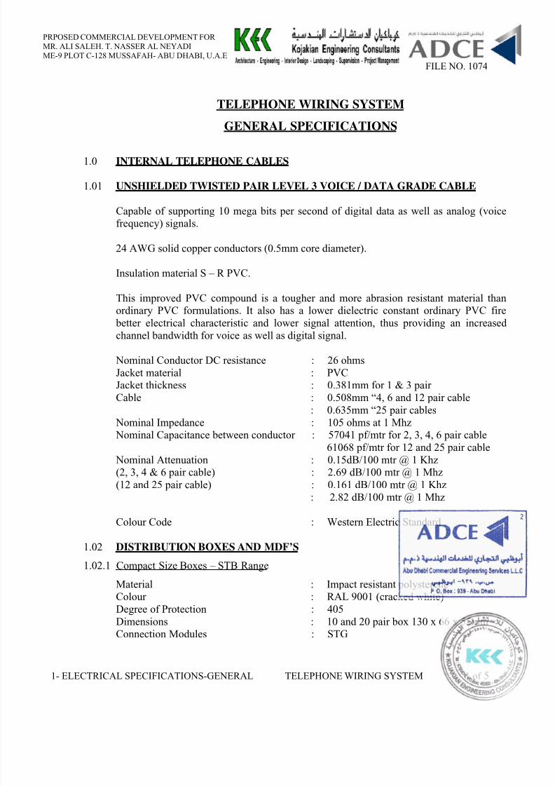
8/10/2019 11a. Electrical Specifications - General
http://slidepdf.com/reader/full/11a-electrical-specifications-general 81/86
PRPOSED COMMERCIAL DEVELOPMENT FORMR. ALI SALEH. T. NASSER AL NEYADIME-9 PLOT C-128 MUSSAFAH- ABU DHABI, U.A.E
FILE NO. 1074
1- ELECTRICAL SPECIFICATIONS-GENERAL TELEPHONE WIRING SYSTEM 1 of 5
TELEPHONE WIRING SYSTEM
GENERAL SPECIFICATIONS
1.0 INTERNAL TELEPHONE CABLES
1.01 UNSHIELDED TWISTED PAIR LEVEL 3 VOICE / DATA GRADE CABLE
Capable of supporting 10 mega bits per second of digital data as well as analog (voicefrequency) signals.
24 AWG solid copper conductors (0.5mm core diameter).
Insulation material S – R PVC.
This improved PVC compound is a tougher and more abrasion resistant material thanordinary PVC formulations. It also has a lower dielectric constant ordinary PVC fire
better electrical characteristic and lower signal attention, thus providing an increasedchannel bandwidth for voice as well as digital signal.
Nominal Conductor DC resistance : 26 ohmsJacket material : PVCJacket thickness : 0.381mm for 1 & 3 pairCable : 0.508mm “4, 6 and 12 pair cable
: 0.635mm “25 pair cables Nominal Impedance : 105 ohms at 1 Mhz Nominal Capacitance between conductor : 57041 pf/mtr for 2, 3, 4, 6 pair cable
61068 pf/mtr for 12 and 25 pair cable Nominal Attenuation : 0.15dB/100 mtr @ 1 Khz(2, 3, 4 & 6 pair cable) : 2.69 dB/100 mtr @ 1 Mhz(12 and 25 pair cable) : 0.161 dB/100 mtr @ 1 Khz
: 2.82 dB/100 mtr @ 1 Mhz
Colour Code : Western Electric Standard
1.02 DISTRIBUTION BOXES AND MDF’S 1.02.1 Compact Size Boxes – STB Range
Material : Impact resistant polystereneColour : RAL 9001 (cracked white)Degree of Protection : 405Dimensions : 10 and 20 pair box 130 x 66 x 55mmConnection Modules : STG
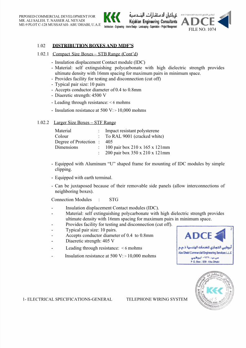
8/10/2019 11a. Electrical Specifications - General
http://slidepdf.com/reader/full/11a-electrical-specifications-general 82/86
PRPOSED COMMERCIAL DEVELOPMENT FORMR. ALI SALEH. T. NASSER AL NEYADIME-9 PLOT C-128 MUSSAFAH- ABU DHABI, U.A.E
FILE NO. 1074
1- ELECTRICAL SPECIFICATIONS-GENERAL TELEPHONE WIRING SYSTEM 1 of 5
1.02 DISTRIBUTION BOXES AND MDF’S
1.02.1 Compact Size Boxes – STB Range (Cont’d)
- Insulation displacement Contact module (IDC)- Material: self extinguishing polycarbonate with high dielectric strength provides
ultimate density with 16mm spacing for maximum pairs in minimum space.- Provides facility for testing and disconnection (cut off)- Typical pair size: 10 pairs- Accepts conductor diameter of 0.4 to 0.8mm- Diaeretic strength: 4500 V
- Leading through resistance: < 6 mohms
- Insulation resistance at 500 V: > 10,000 mohms
1.02.2 Larger Size Boxes – STF RangeMaterial : Impact resistant polystereneColour : To RAL 9001 (cracked white)Degree of Protection : 405Dimensions : 100 pair box 210 x 165 x 121mm
: 200 pair box 350 x 210 x 121mm
- Equipped with Aluminum “U” shaped frame for mounting of IDC modules by simpleclipping.
- Equipped with earth terminal.
- Can be juxtaposed because of their removable side panels (allow interconnections ofneighboring boxes).
Connection Modules : STG
- Insulation displacement Contact modules (IDC).- Material: self extinguishing polycarbonate with high dielectric strength provides
ultimate density with 16mm spacing for maximum pairs in minimum space.- Provides facility for testing and disconnection (cut off).- Typical pair size: 10 pairs.- Accepts conductor diameter of 0.4 to 0.8mm- Diaeretic strength: 405 V
- Leading through resistance: < 6 mohms
- Insulation resistance at 500 V: > 10,000 mohms
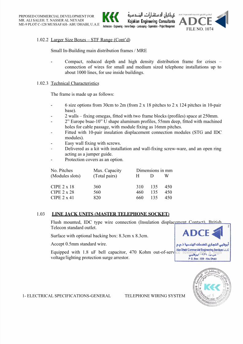
8/10/2019 11a. Electrical Specifications - General
http://slidepdf.com/reader/full/11a-electrical-specifications-general 83/86
PRPOSED COMMERCIAL DEVELOPMENT FORMR. ALI SALEH. T. NASSER AL NEYADIME-9 PLOT C-128 MUSSAFAH- ABU DHABI, U.A.E
FILE NO. 1074
1- ELECTRICAL SPECIFICATIONS-GENERAL TELEPHONE WIRING SYSTEM 1 of 5
1.02.2 Larger Size Boxes – STF Range (Cont’d)
Small In-Building main distribution frames / MRE
- Compact, reduced depth and high density distribution frame for crises –connection of wires for small and medium sized telephone installations up toabout 1000 lines, for use inside buildings.
1.02.3 Technical Characteristics
The frame is made up as follows:
- 6 size options from 30cm to 2m (from 2 x 18 pitches to 2 x 124 pitches in 10-pair base).
- 2 walls – fixing omegas, fitted with two frame blocks (profiles) space at 250mm.- 2” Europe bsae-10” U shape aluminum profiles, 55mm deep, fitted with machined
holes for cable passage, with module fixing as 16mm pitches.- Fitted with 10-pair insulation displacement connection modules (STG and IDC
modules).- Easy wall fixing with screws.- Delivered as a kit with installation and wall-fixing screw-ware, and an open ring
acting as a jumper guide.- Protection covers as an option.
No. Pitches Max. Capacity Dimensions in mm(Modules slots) (Total pairs) H D W
CIPE 2 x 18 360 310 135 450CIPE 2 x 28 560 460 135 450CIPE 2 x 41 820 660 135 450
1.03 LINE JACK UNITS (MASTER TELEPHONE SOCKET)
Flush mounted, IDC type wire connection (Insulation displacement Contact), BritishTelecon standard outlet.
Surface with optional backing box: 8.3cm x 8.3cm.
Accept 0.5mm standard wire.
Equipped with 1.8 uF bell capacitor, 470 Kohm out-of-service resistor and a highvoltage/lighting protection surge arrestor.
8/10/2019 11a. Electrical Specifications - General
http://slidepdf.com/reader/full/11a-electrical-specifications-general 84/86
8/10/2019 11a. Electrical Specifications - General
http://slidepdf.com/reader/full/11a-electrical-specifications-general 85/86
PRPOSED COMMERCIAL DEVELOPMENT FORMR. ALI SALEH. T. NASSER AL NEYADIME-9 PLOT C-128 MUSSAFAH- ABU DHABI, U.A.E
FILE NO. 1074
1-ELECTRICAL SPECS. - GENERAL CALL BELL SYSTEM 2 of 3
CALL BELL SYSTEM
GENERAL SPECIFICATIONS
INDEX
1.0 GENERAL
1.1 THREE TONE ELECTRONIC CHIME
1.2 DOOR BELL PUSH BUTTON
1.3 POWER SUPPLY
8/10/2019 11a. Electrical Specifications - General
http://slidepdf.com/reader/full/11a-electrical-specifications-general 86/86
PRPOSED COMMERCIAL DEVELOPMENT FORMR. ALI SALEH. T. NASSER AL NEYADIME-9 PLOT C-128 MUSSAFAH- ABU DHABI, U.A.E
FILE NO. 1074
CALL BELL SYSTEM
GENERAL SPECIFICATIONS
1.0 GENERAL
The Contractor shall supply, install, test and commission a modernElectronic Call Bell system to the Building.
The Contractor shall submit a complete proposal with drawings, detailedcatalogues wiring diagrams etc. for prior to installation.
1.1 THREE TONE ELECTRONIC CHIME
One Electronic Chime in Ivory colour ABS Plastic housing shall be installedin each apartments of the building. The dimensions of the chime shall be 140x 50mm. The Chime shall be installed on recessed switch boxes or withfixing screws.
The Chime shall be supplied by 10 -15 V A.C. A 9V Battery shall behoused inside the Chime which will guarantee working in case of a powerfailure. A Potentiometer inside the chime shall regulate sound intensity.
1.2 DOOR BELL PUSH BUTTON
Door Bell Push Button shall be in Anodized Aluminum frame and back boxcomplete with cover in beige plastic.
1.3 POWER SUPPLY UNIT