
11011 - Super 1050 man v 1 - Voice Communications Inc. 1050 User Ma… · Die Adjustments 15...
32
Super 1050 Instruction Manual Version 1.1 illon recision Products, Inc. Manufacturers of The World's Finest Loading Equipment
Transcript of 11011 - Super 1050 man v 1 - Voice Communications Inc. 1050 User Ma… · Die Adjustments 15...

Super 1050Instruction Manual
Version 1.1
illonrecision
Products, Inc.
Manufacturers of The World's FinestLoading Equipment
Table of Contents
Contents 4
How the Super 1050 Works: Stations 1 - 8 5
Super 1050 Assembly 6
Powder Measure Adjustment 8
Primer Magazine 9
Electric Casefeeder 10
Review: How the Super 1050 Works: Stations 1 - 8 10
To Begin Reloading 10
Adjustments 12
Primer Seating Depth - Station 4 11
Casefeeder 12
Handle 12
Swager 12
Swage Conversion & Adjustment 12
Primer System Change Over Instructions 13
Toolhead Removal 14
Shellplate Removal 15
Casefeed Plunger Conversion 15
Die Adjustments 15
Sizing/Decapping Die - Station 2 15
Back-up Expander Die & Swager - Station 3 16
Powder Die - Station 5 16
Bullet Seating Die - Station 7 17 - 18
Crimp Die - Station 8 18
RL 1050 vs. Super 1050 19
Trouble Shooting 20
Maintenance 21
Lubrication Points 22 - 23
Caliber Conversion Charts 24 - 25
Parts List 26
Schematics 27 - 31
#11011 Spot Manuals Super 1050 manual folder SUPER 1050 Manual v1.1 9/01 WJC
Warranty AgreementThe Dillon Super 1050 reloader has been designed as a
commercial machine. Our expectation is that its lifeexpectancy will be in excess of two million rounds ofloaded ammunition. All Super 1050 machines are war-ranted for life from defects in material or workmanship,plus a one-year, 100% warranty against normal wear. Allelectrical/electronic components in Dillon equipment arecovered by a one-year warranty.
Mandatory Safety MeasuresThe reloading of ammunition and the handling of
components (gun powder and primers) is inherently dan-gerous, indeed shooting firearms is inherently dangerous.Accidents can and do occur, sometimes with disastrousresults including, but not limited to, loss of vision, hear-ing or life. These accidents are nondiscriminatory, theyoccur with both the novice and the experienced reloader.
Dillon Precision Products has consciously designedthe Super 1050 with this in mind. We’ve shielded theprimer magazine and machined clearance holes for theelimination of powder and primer residue. In short, wehave done everything we know how, to make the use ofour machine as safe as possible. We cannot however,guarantee your complete safety. In order to minimizeyour risk, use common sense when reloading and fol-low these basic rules:
Never operate the machine without ear and eye pro-tection on. Call our customer service department at(800) 223-4570 for information on the wide variety ofshooting/safety glasses and hearing protection thatDillon has to offer.• PAY ATTENTION: Load only when you can give yourcomplete attention to the loading process. Don’t watchtelevision or try to carry on a conversation and load at thesame time. Watch the automatic systems operate andmake sure they are functioning properly. If you are inter-rupted or must leave and come back to your loading,always inspect the cases at every station to insure that theproper operations have been accomplished.• SMOKING: Do not smoke while reloading or allowanyone else to smoke in your reloading area. Do notallow open flames in reloading area.• SAFETY DEVICES: Do not remove any safety devicesfrom your machine or modify your machine in any way.• LEAD WARNING: Be sure to have proper ventilationwhile handling lead components or when shooting leadbullets. Lead is known to cause birth defects, other repro-ductive harm and cancer. Wash your hands thoroughlyafter handling anything made of lead.• LOADS AND LENGTHS: Avoid maximum loads andpressures at all times. Use only recommended loadsfrom manuals and information supplied by reliablecomponent manufacturers and suppliers. Since DillonPrecision has no control over the components whichmay be used on their equipment, no responsibility isimplied or assumed for results obtained through the useof any such components.
Seat bullets as close to maximum cartridge length aspossible. Under some conditions, seating bullets exces-sively deep can raise pressures to unsafe levels. Refer to areliable loading manual for overall length (OAL).• QUALITY CHECKS: Every 50-100 rounds, performperiodic quality control checks on the ammunition beingproduced. Check the amount of powder being droppedand primer supply.• RELOADING AREA: Keep your components safelystored. Clear your work area of loose powder, primersand other flammables before loading.• COMPONENTS: Never have more than one type ofpowder in your reloading area at a time. The risk of amix-up is too great. Keep powder containers closed.
Be sure to inspect brass prior to reloading for flaws,cracks, splits or defects. Throw these cases away.
Keep components and ammunition out of reach ofchildren.• BLACK POWDER: Do not use black powder or blackpowder substitutes in any Dillon powder measure.Loading black powder cartridges requires specializedloading equipment and techniques. Failure to do so canresult in severe injury or death.• PRIMERS: Never force primers. If they get stuck in theoperation of the machine, disassemble it and gentlyremove the obstruction.
Never attempt to clear primers that are stuck in eitherthe primer pickup tube or the primer magazine tube.Never, under any circumstances, insert any type of rod toattempt to force stuck primers out of these tubes. Tryingto force primers out of the tube will cause the primers toexplode causing serious injury or even death.
If primers get stuck in a primer magazine or pickuptube flood the tube with a penetrating oil (WD-40), throwthe tube in the garbage and call us for a free replacement.
Never attempt to deprime live primers – eventuallyone will go off. When it does it will detonate the others inthe spent primer cup. Depriming live primers is the singlemost dangerous thing you can do in reloading and cancause grave injury or death.• LOADED AMMUNITION: Properly label all of yourloaded ammunition (Date, Type of Bullet, Primer, Powder,Powder Charge, etc.).• BE PATIENT: Our loading equipment is conservativelyrated and you should have no trouble achieving the pub-lished rates with a smooth, steady hand. If somethingdoesn’t seem right, stop, look and listen. If the problem orthe solution isn’t obvious, call us. The reloading bench isno place to get into a hurry.
We have done everything we know how to make yourmachine as safe as possible. We cannot, however, guaran-tee your complete safety. To minimize your risk, use com-mon sense when reloading and follow these basic rules.• REMEMBER: If your machine does not perform to yourexpectations, or if you are having technical difficulties,give us a call. Technical Support (800) 223-4570
4
Contents
items not to scale
items not to scale
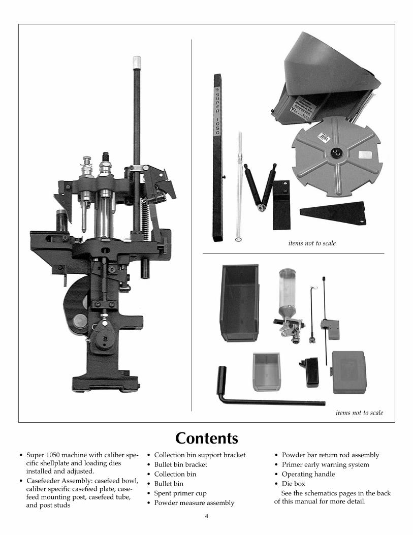
• Super 1050 machine with caliber spe-cific shellplate and loading diesinstalled and adjusted.
• Casefeeder Assembly: casefeed bowl,caliber specific casefeed plate, case-feed mounting post, casefeed tube,and post studs
• Collection bin support bracket• Bullet bin bracket• Collection bin• Bullet bin• Spent primer cup• Powder measure assembly
• Powder bar return rod assembly• Primer early warning system• Operating handle• Die box
See the schematics pages in the backof this manual for more detail.

How the Super 1050 WorksStations 1 - 8 (counterclockwise)toolhead and dies cut away for clarity
Station 1: Empty cases are automati-cally inserted into the shellplate via theelectric casefeeder.
Station 2: Here the spent cartridgecases are resized and deprimed.
Station 3: This station is totallyunique. The case is supported from theinside and slightly expanded (notbelled) while simultaneously a swageris driven into the primer pocket toremove any crimp.
Station 4: A new primer is installedat this station. The spring drivenprimer slide is extremely smooth. Thesteel shrouded primer magazine iscapped with an electronic EarlyWarning Device to let you knowwhen you’re down to approximatelythree primers.
Station 5: Here the case is belledand powder is dropped by the case-activated powder measure. It isextremely accurate and will not droppowder unless a case is present. DillonPrecision offers an optional accessory tobe utilized with the automatic powdermeasure at this station – Dillon’s LowPowder Sensor provides an audible andvisual reminder when it’s time to refillthe powder reservoir.
Station 6: This station is open toallow for case inspection.
Station 7: The bullet is seated to itsproper depth at this station.
Station 8: In this station, the bullet iscrimped into place. The cartridge isthen automatically ejected into a collec-tion bin.
Your dies have been adjusted at thefactory. Before you change anything, tryit the way it is, once you thoroughlyunderstand the machine’s operation,make whatever adjustments to the diesyou feel necessary.
Reminder: There may be some varia-tion due to components.
5
Station 5 - Here the case mouth is belledand powder dispensed.
Station 1 - The casefeed plunger inserts thecase into the shellplate.
Station 2 - Here, spent cartridge cases areresized and deprimed.
Station 7 - In this station, the bullet is seat-ed to its proper depth.
Station 8 - Here the case is crimped andthen ejected out of the shellplate with thenext pull of the handle.
Station 3 - Here the case mouth is expand-ed while a rod supports the case base forswaging.
Super 1050 AssemblyYour new Super 1050 has been
assembled at the factory. All of theadjustments necessary to reload havealready been made, in fact we’veeven adjusted the dies to reload thecaliber you have chosen. However,before you can reload you must dosome minor assembly.
Due to variations in components,check all stations for proper settingsbefore loading ammunition. It isabsolutely necessary that you read thefollowing instructions.
If you get stuck on something thatyou don’t understand, call (800) 223-4570 for technical assistance.
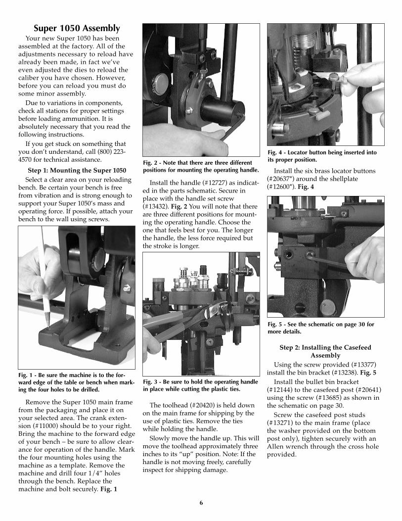
Step 1: Mounting the Super 1050 Select a clear area on your reloading
bench. Be certain your bench is freefrom vibration and is strong enough tosupport your Super 1050’s mass andoperating force. If possible, attach yourbench to the wall using screws.
Remove the Super 1050 main framefrom the packaging and place it onyour selected area. The crank exten-sion (#11000) should be to your right.Bring the machine to the forward edgeof your bench – be sure to allow clear-ance for operation of the handle. Markthe four mounting holes using themachine as a template. Remove themachine and drill four 1/4” holesthrough the bench. Replace themachine and bolt securely. Fig. 1
Install the handle (#12727) as indicat-ed in the parts schematic. Secure inplace with the handle set screw(#13432). Fig. 2 You will note that thereare three different positions for mount-ing the operating handle. Choose theone that feels best for you. The longerthe handle, the less force required butthe stroke is longer.
The toolhead (#20420) is held downon the main frame for shipping by theuse of plastic ties. Remove the tieswhile holding the handle.
Slowly move the handle up. This willmove the toolhead approximately threeinches to its “up” position. Note: If thehandle is not moving freely, carefullyinspect for shipping damage.
Install the six brass locator buttons(#20637*) around the shellplate(#12600*). Fig. 4
Step 2: Installing the CasefeedAssembly
Using the screw provided (#13377)install the bin bracket (#13238). Fig. 5
Install the bullet bin bracket(#12144) to the casefeed post (#20641)using the screw (#13685) as shown inthe schematic on page 30.
Screw the casefeed post studs(#13271) to the main frame (placethe washer provided on the bottompost only), tighten securely with anAllen wrench through the cross holeprovided.
Fig. 1 - Be sure the machine is to the for-ward edge of the table or bench when mark-ing the four holes to be drilled.
Fig. 2 - Note that there are three differentpositions for mounting the operating handle.
Fig. 3 - Be sure to hold the operating handlein place while cutting the plastic ties.
Fig. 4 - Locator button being inserted intoits proper position.
Fig. 5 - See the schematic on page 30 formore details.
6
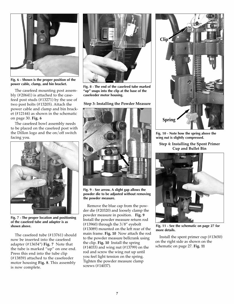
The casefeed mounting post assem-bly (#20641) is attached to the case-feed post studs (#13271) by the use oftwo post bolts (#13205). Attach thepower cable and clamp and bin brack-et (#12144) as shown in the schematicon page 30. Fig. 6
The casefeed bowl assembly needsto be placed on the casefeed post withthe Dillon logo and the on/off switchfacing you.
The casefeed tube (#13761) shouldnow be inserted into the casefeedadapter (#13654*) Fig. 7 Note thatthe tube is marked “up” on one end.Press this end into the tube clip(#13859) attached to the casefeedermotor housing Fig. 8. This assemblyis now complete.
Step 3: Installing the Powder Measure
Remove the blue cap from the pow-der die (#20320) and loosely clamp thepowder measure in position. Fig. 9Install the powder measure return rod(#13960) through the 3/8” eyebolt(#13089) mounted on the left rear of themain frame. Fig. 10 Now attach the rodto the powder measure bellcrank usingthe clip. Fig. 10 Install the spring(#14033) and wing nut (#13799) on therod and screw the wing nut up untilyou feel light tension on the spring.Tighten the powder measure clampscrews (#14037).
Step 4: Installing the Spent PrimerCup and Bullet Bin
Install the spent primer cup (#13650)on the right side as shown on theschematic on page 27. Fig. 11
7
Fig. 6 - Shown is the proper position of thepower cable, clamp, and bin bracket.
Fig. 7 - The proper location and positioningof the casefeed tube and adapter is asshown above.
Fig. 8 - The end of the casefeed tube marked“up” snaps into the clip at the base of thecasefeeder motor housing.
Fig. 9 - See arrow. A slight gap allows thepowder die to be adjusted without removingthe powder measure.
Fig. 10 - Note how the spring above thewing nut is slightly compressed.
Clip
Spring
Fig. 11 - See the schematic on page 27 formore details.
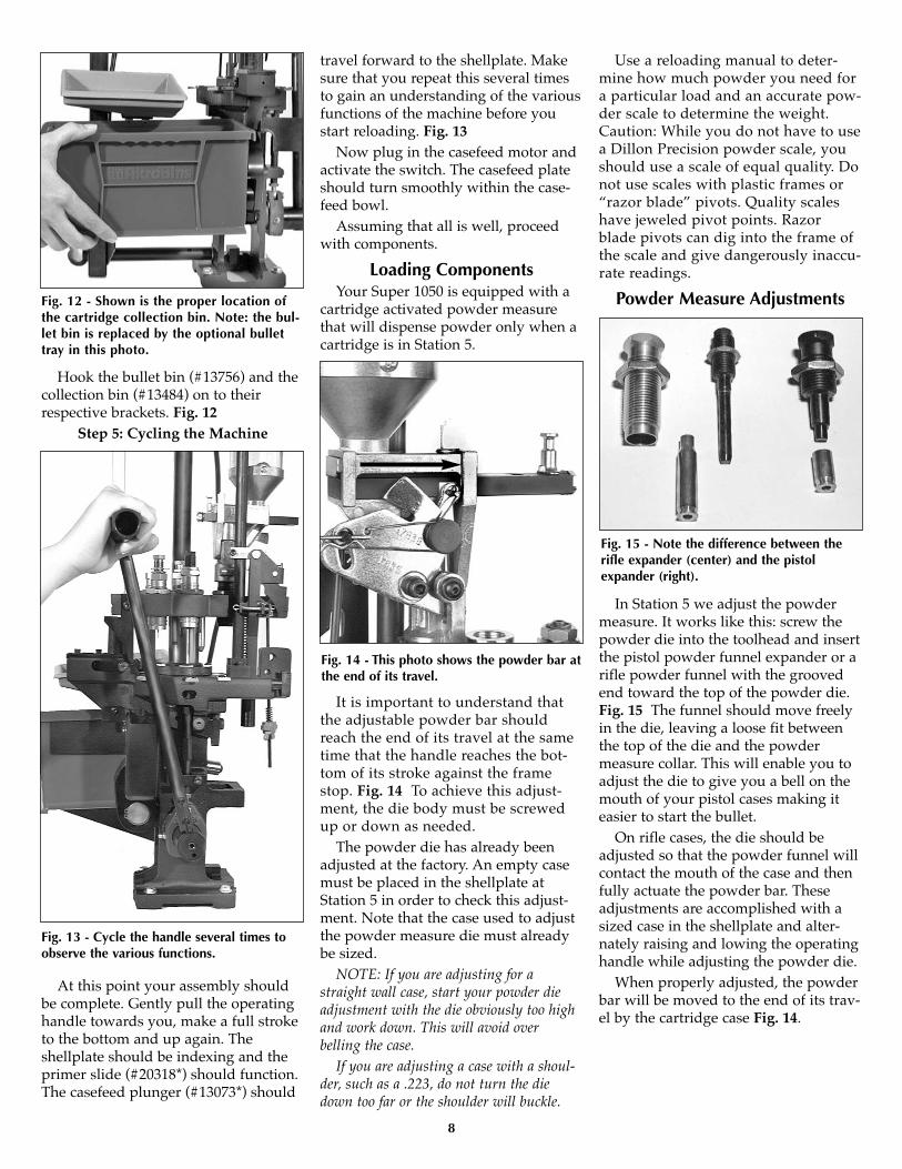
Hook the bullet bin (#13756) and thecollection bin (#13484) on to theirrespective brackets. Fig. 12
Step 5: Cycling the Machine
At this point your assembly shouldbe complete. Gently pull the operatinghandle towards you, make a full stroketo the bottom and up again. Theshellplate should be indexing and theprimer slide (#20318*) should function.The casefeed plunger (#13073*) should
travel forward to the shellplate. Makesure that you repeat this several timesto gain an understanding of the variousfunctions of the machine before youstart reloading. Fig. 13
Now plug in the casefeed motor andactivate the switch. The casefeed plateshould turn smoothly within the case-feed bowl.
Assuming that all is well, proceedwith components.
Loading ComponentsYour Super 1050 is equipped with a
cartridge activated powder measurethat will dispense powder only when acartridge is in Station 5.
It is important to understand thatthe adjustable powder bar shouldreach the end of its travel at the sametime that the handle reaches the bot-tom of its stroke against the framestop. Fig. 14 To achieve this adjust-ment, the die body must be screwedup or down as needed.
The powder die has already beenadjusted at the factory. An empty casemust be placed in the shellplate atStation 5 in order to check this adjust-ment. Note that the case used to adjustthe powder measure die must alreadybe sized.
NOTE: If you are adjusting for astraight wall case, start your powder dieadjustment with the die obviously too highand work down. This will avoid overbelling the case.
If you are adjusting a case with a shoul-der, such as a .223, do not turn the diedown too far or the shoulder will buckle.
Use a reloading manual to deter-mine how much powder you need fora particular load and an accurate pow-der scale to determine the weight.Caution: While you do not have to usea Dillon Precision powder scale, youshould use a scale of equal quality. Donot use scales with plastic frames or“razor blade” pivots. Quality scaleshave jeweled pivot points. Razorblade pivots can dig into the frame ofthe scale and give dangerously inaccu-rate readings.
Powder Measure Adjustments
In Station 5 we adjust the powdermeasure. It works like this: screw thepowder die into the toolhead and insertthe pistol powder funnel expander or arifle powder funnel with the groovedend toward the top of the powder die.Fig. 15 The funnel should move freelyin the die, leaving a loose fit betweenthe top of the die and the powdermeasure collar. This will enable you toadjust the die to give you a bell on themouth of your pistol cases making iteasier to start the bullet.
On rifle cases, the die should beadjusted so that the powder funnel willcontact the mouth of the case and thenfully actuate the powder bar. Theseadjustments are accomplished with asized case in the shellplate and alter-nately raising and lowing the operatinghandle while adjusting the powder die.
When properly adjusted, the powderbar will be moved to the end of its trav-el by the cartridge case Fig. 14.
8
Fig. 13 - Cycle the handle several times toobserve the various functions.
Fig. 14 - This photo shows the powder bar atthe end of its travel.
Fig. 15 - Note the difference between therifle expander (center) and the pistolexpander (right).
Fig. 12 - Shown is the proper location ofthe cartridge collection bin. Note: the bul-let bin is replaced by the optional bullettray in this photo.
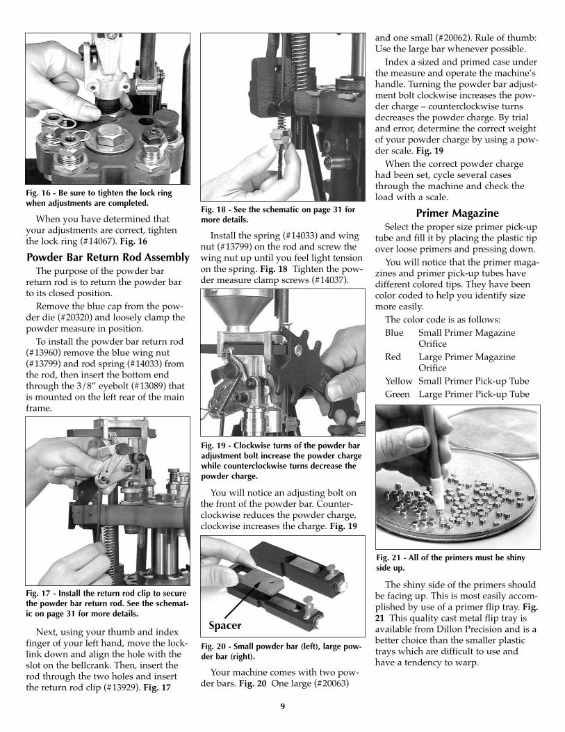
When you have determined thatyour adjustments are correct, tightenthe lock ring (#14067). Fig. 16
Powder Bar Return Rod AssemblyThe purpose of the powder bar
return rod is to return the powder barto its closed position.
Remove the blue cap from the pow-der die (#20320) and loosely clamp thepowder measure in position.
To install the powder bar return rod(#13960) remove the blue wing nut(#13799) and rod spring (#14033) fromthe rod, then insert the bottom endthrough the 3/8” eyebolt (#13089) thatis mounted on the left rear of the mainframe.
Next, using your thumb and indexfinger of your left hand, move the lock-link down and align the hole with theslot on the bellcrank. Then, insert therod through the two holes and insertthe return rod clip (#13929). Fig. 17
Install the spring (#14033) and wingnut (#13799) on the rod and screw thewing nut up until you feel light tensionon the spring. Fig. 18 Tighten the pow-der measure clamp screws (#14037).
You will notice an adjusting bolt onthe front of the powder bar. Counter-clockwise reduces the powder charge,clockwise increases the charge. Fig. 19
Your machine comes with two pow-der bars. Fig. 20 One large (#20063)
and one small (#20062). Rule of thumb:Use the large bar whenever possible.
Index a sized and primed case underthe measure and operate the machine’shandle. Turning the powder bar adjust-ment bolt clockwise increases the pow-der charge – counterclockwise turnsdecreases the powder charge. By trialand error, determine the correct weightof your powder charge by using a pow-der scale. Fig. 19
When the correct powder chargehad been set, cycle several casesthrough the machine and check theload with a scale.
Primer MagazineSelect the proper size primer pick-up
tube and fill it by placing the plastic tipover loose primers and pressing down.
You will notice that the primer maga-zines and primer pick-up tubes havedifferent colored tips. They have beencolor coded to help you identify sizemore easily.
The color code is as follows:Blue Small Primer Magazine
OrificeRed Large Primer Magazine
OrificeYellow Small Primer Pick-up TubeGreen Large Primer Pick-up Tube
The shiny side of the primers shouldbe facing up. This is most easily accom-plished by use of a primer flip tray. Fig.21 This quality cast metal flip tray isavailable from Dillon Precision and is abetter choice than the smaller plastictrays which are difficult to use andhave a tendency to warp.
Fig. 16 - Be sure to tighten the lock ringwhen adjustments are completed.
Fig. 17 - Install the return rod clip to securethe powder bar return rod. See the schemat-ic on page 31 for more details.
Fig. 18 - See the schematic on page 31 formore details.
Fig. 19 - Clockwise turns of the powder baradjustment bolt increase the powder chargewhile counterclockwise turns decrease thepowder charge.
Fig. 20 - Small powder bar (left), large pow-der bar (right).
Spacer
Fig. 21 - All of the primers must be shinyside up.
9

Once you’ve filled the pick-up tube,make sure the little retaining clip is inplace at the top of the tube. Fig. 22Pivot the switch lever (#13864) awayfrom the Early Warning System hous-ing and invert the pick-up tube overthe primer shield cap (#13957). Youwill notice the cap has a bevel to helpyou funnel the primers in. Hold thetube in place as shown in Fig. 22, pullthe retaining pin and allow theprimers to drop into the magazine.Pivot the switch the lever back overthe Early Warning System housing.Gently slide the follower rod downthrough the switch lever and into theprimer magazine tube. When you arenearly out of primers, approximatelythree remaining, the follower will acti-vate the buzzer.
The Electric Casefeeder
Use only clean cartridge cases thathave been inspected for any potentialproblems; split cases, rocks or smaller
caliber cartridges that may be hidden inlarger caliber cartridges. Fig 23Warning: Be sure that no loaded roundsare mixed with your empty cases. It ispossible to feed a blunt nosed cartridgelike a .38 Sp. WC into the shellplateupside down and explode it when it ishit by the decap pin.
Now fill the casefeed bowl withapproximately 500 pistol cases or about350 rifle cases. Fig 24
Your Super 1050 is now charged withcomponents and ready to go, but beforeyou start reloading, read the followingexplanation of the sequence of the eightreloading stations and the processesthat are done at each station.
Review: How the Super1050 Works
Stations 1 - 8 (counterclockwise)Station 1: Empty cases are automati-
cally inserted into the shellplate via theelectric casefeeder.
Station 2: Here the spent cartridgecases are resized and deprimed.
Station 3: This station is totallyunique. The case is supported from theinside and slightly expanded (notbelled) while simultaneously a swageris driven into the primer pocket toremove any crimp.
Station 4: A new primer is installedat this station. The spring drivenprimer slide is extremely smooth. Thesteel shrouded primer magazine iscapped with an electronic EarlyWarning Device to let you knowwhen you’re down to approximatelythree primers.
Station 5: Here the case is belledand powder is dropped by the case-activated powder measure. It isextremely accurate and will not droppowder unless a case is present. DillonPrecision offers an optional accessory tobe utilized with the automatic powdermeasure at this station – Dillon’s LowPowder Sensor provides an audible andvisual reminder when it’s time to refillthe powder reservoir.
Station 6: This station is open toallow for case inspection.
Station 7: The bullet is seated to itsproper depth at this station.
Station 8: In this station, the bullet iscrimped into place. The cartridge isthen automatically ejected into a collec-tion bin.
As stated earlier, your dies havebeen adjusted at the factory. Beforeyou change anything, try it the way itis, once you thoroughly understandthe machine’s operation, make what-ever adjustments to the dies you feelnecessary.
Reminder: There may be some varia-tion due to components.
To Begin ReloadingTurn on the switch on the front of the
casefeed motor housing. The casefeederplate should begin to turn. Cases willbegin to dispense, base down, into theclear plastic casefeed tube. The motor
10
Fig. 22 - When installing primers into theprimer magazine, be sure the pick-up tubecenters itself before pulling the clip.
Fig. 24 - The casefeed bowl will holdapproximately 500 pistol cases or 350 riflecases. Do not overload the casefeed bowl.
Fig. 23 - When loading, use only cleanedand inspected cartridge cases.
Fig. 25 - Dillon’s Low Powder Sensor givesan audible and visual warning when thepowder reservoir gets low.

will continue to run until the tube isfull, at which point a micro-switch willtemporarily stop the case flow.
From this point the casefeeder willautomatically fill the tube as youreload. If the casefeeder does not func-tion properly or the cases do not fallbase down, refer to the TroubleShooting section of this manual.
Pull the operating handle smoothlyto the bottom stop, then raise the han-dle, a case has been fed to Station 1.Cycle the handle again, strive to besmooth in your operation.
The first case should be indexed toStation 2. Cycle the handle again.
It is not necessary to apply any forceon the upstroke of the handle. All youare doing on the upstroke is indexingthe shellplate. Remember that primingis done on the down stroke. A slowmeasured upstroke gives you lots oftime to pick up the next bullet and
ready it for seating. If you count onesecond down, and one second up,you’ll have a good pace.
The first case should now be inStation 3 with a case in Stations 1 & 2as well. Cycle the handle again. Thecase is swaged and expanded at Station3. Observe the swage operating part(#20314*), if the swage is proper, pro-ceed – if not see items 3 and 4 in theTrouble Shooting section of this manu-al. Cycle the handle again and the casegets primed at Station 4.
If the primer is not seated properly(too high or too deep) you will need toadjust the primer push rod (#12819).Clockwise turns of the primer push rodwill cause the primer to be seated deep-er while counterclockwise turns willseat the primer higher.
The first case in the sequenceshould now be primed and at Station
5. Remove the locator button(#20637*), extract the round and checkthe primer. If everything looks okay,replace the case and button and pro-ceed. However, if the primer is notseated properly (too high or too deep)you will need to adjust the primer pushrod (#12819). Clockwise turns of theprimer push rod will cause the primerto be seated deeper while counterclock-wise turns will seat the primer higher.
Cycle the handle again, the automat-ic powder measure will drop the chargeyou’ve selected. Pistol casemouths willbe belled at this time. Look through theinspection hole in Station 6 – youshould be able to see your powdercharge in the case.
Cycle the handle again. Now, withyour left hand, place a bullet on thepowder-charged case at Station 7 andcycle the handle. Your bullet will beseated to its proper depth, if not, a sim-
11
Station 5 - Here the case mouth is belledand powder dispensed.
Station 1 - The casefeed plunger inserts thecase into the shellplate.
Station 2 - Here, spent cartridge cases areresized and deprimed.
Station 7 - In this station, the bullet is seat-ed to its proper depth.
Station 8 - Here the case is crimped andthen ejected out of the shellplate with thenext pull of the handle.
Station 3 - Here the case mouth is expand-ed while a rod supports the case base forswaging.
ple height adjustment to the seatingstem may be necessary. Refer to a load-ing manual for proper loaded length(OAL). Cycle the handle again andcheck for crimp at Station 8. Refer toTrouble Shooting item 8 for adjust-ments if necessary. Add a bullet, cycleagain. Your first loaded round shouldnow be ejected into the collection bin.
If all has gone well to this pointyou’ve got it made. Just keep addingbullets, watch your fingers so theydon’t get caught and don’t hurry. Justtry to be smooth in your operation. Thespeed will come naturally and you’ll bedoing a thousand rounds per hourbefore you even realize it.
The following are some adjustmentsuggestions as well as TroubleShooting hints.
Adjustments
CasefeederIt may be necessary to readjust the
micro-switch for different calibers.Cases may become lodged betweenthe micro-switch and the tube wall.The other extreme is the case failing toput enough pressure on the micro-switch to shut off the system causingit to continue running and over flow-ing the tube. Fig. 26
The casefeed spacer (#13703) sup-plied in the accessory package, is tobe used when you are reloading .41Mag, .44 Mag, .357 Mag, .30 Carbine,or .45 Colt.
Remove the two clutch screws(#13732), lock washer (#13813) andupper clutch (#13632) and the case-feed plate. Place the spacer on theshoulder of the lower clutch andreassemble – see the schematic onpage 31 for more details. The casefeedplate should now be approximately1/8” above the floor of the casefeedbowl. Note: Make sure the casefeedplate is centered in the bowl. Fig. 27
HandleThe operating handle is adjustable to
three different length settings. Choosethe one most comfortable for youroperation. Loosen the set screw(#13432) then retighten when the han-dle is in the most comfortable position.
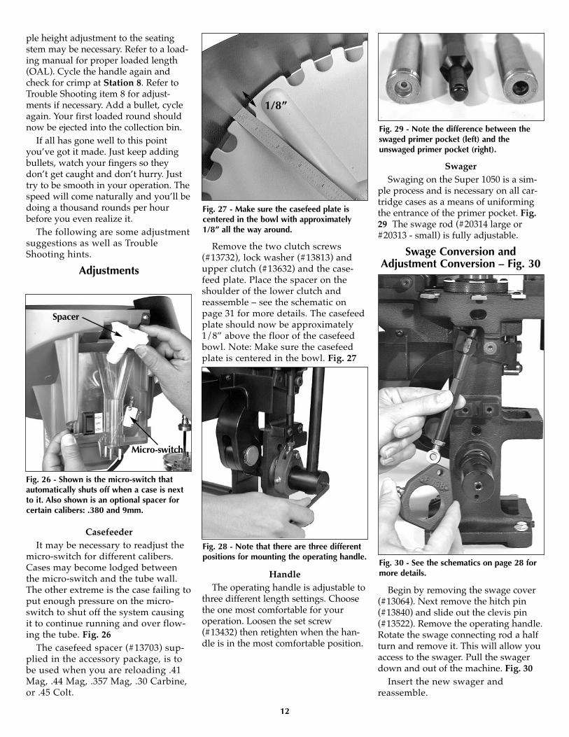
SwagerSwaging on the Super 1050 is a sim-
ple process and is necessary on all car-tridge cases as a means of uniformingthe entrance of the primer pocket. Fig.29 The swage rod (#20314 large or#20313 - small) is fully adjustable.
Swage Conversion andAdjustment Conversion – Fig. 30
Begin by removing the swage cover(#13064). Next remove the hitch pin(#13840) and slide out the clevis pin(#13522). Remove the operating handle.Rotate the swage connecting rod a halfturn and remove it. This will allow youaccess to the swager. Pull the swagerdown and out of the machine. Fig. 30
Insert the new swager andreassemble.
12
Fig. 26 - Shown is the micro-switch thatautomatically shuts off when a case is nextto it. Also shown is an optional spacer forcertain calibers: .380 and 9mm.
Micro-switch
Spacer
Fig. 27 - Make sure the casefeed plate iscentered in the bowl with approximately1/8” all the way around.
Fig. 30 - See the schematics on page 28 formore details.
Fig. 29 - Note the difference between theswaged primer pocket (left) and theunswaged primer pocket (right).
Fig. 28 - Note that there are three differentpositions for mounting the operating handle.
1/8”
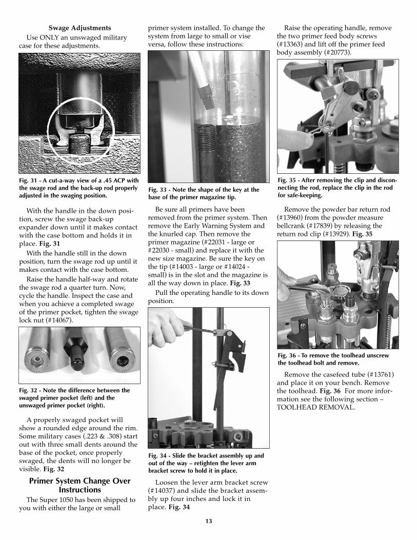
Swage AdjustmentsUse ONLY an unswaged military
case for these adjustments.
With the handle in the down posi-tion, screw the swage back-upexpander down until it makes contactwith the case bottom and holds it inplace. Fig. 31
With the handle still in the downposition, turn the swage rod up until itmakes contact with the case bottom.
Raise the handle half-way and rotatethe swage rod a quarter turn. Now,cycle the handle. Inspect the case andwhen you achieve a completed swageof the primer pocket, tighten the swagelock nut (#14067).
A properly swaged pocket willshow a rounded edge around the rim.Some military cases (.223 & .308) startout with three small dents around thebase of the pocket, once properlyswaged, the dents will no longer bevisible. Fig. 32
Primer System Change OverInstructions
The Super 1050 has been shipped toyou with either the large or small
primer system installed. To change thesystem from large to small or viseversa, follow these instructions:
Be sure all primers have beenremoved from the primer system. Thenremove the Early Warning System andthe knurled cap. Then remove theprimer magazine (#22031 - large or#22030 - small) and replace it with thenew size magazine. Be sure the key onthe tip (#14003 - large or #14024 -small) is in the slot and the magazine isall the way down in place. Fig. 33
Pull the operating handle to its downposition.
Loosen the lever arm bracket screw(#14037) and slide the bracket assem-bly up four inches and lock it inplace. Fig. 34
Raise the operating handle, removethe two primer feed body screws(#13363) and lift off the primer feedbody assembly (#20773).
Remove the powder bar return rod(#13960) from the powder measurebellcrank (#17839) by releasing thereturn rod clip (#13929). Fig. 35
Remove the casefeed tube (#13761)and place it on your bench. Removethe toolhead. Fig. 36 For more infor-mation see the following section –TOOLHEAD REMOVAL.
13
Fig. 32 - Note the difference between theswaged primer pocket (left) and theunswaged primer pocket (right).
Fig. 31 - A cut-a-way view of a .45 ACP withthe swage rod and the back-up rod properlyadjusted in the swaging position.
Fig. 33 - Note the shape of the key at thebase of the primer magazine tip.
Fig. 34 - Slide the bracket assembly up andout of the way – retighten the lever armbracket screw to hold it in place.
Fig. 35 - After removing the clip and discon-necting the rod, replace the clip in the rodfor safe-keeping.
Fig. 36 - To remove the toolhead unscrewthe toolhead bolt and remove.

Now remove the shellplate locknut (#13425) by loosening the fourlocator tab screws (#13895) about fourfull turns. Fig. 37
Loosen the ejector tab screw(#13896) and swing the ejector tab(#13189) out of the way. Fig. 38 Next,slide the casefeed plunger (#13073*)back and remove the shellplate.
Rotate the primer slide stop (#13108)90˚. This will allow you to remove, and
replace, the primer slide (#20318 - largeor #20317 - small). Fig. 39
Next, remove the bushing (#13031 -large or #13222 - small); spring(#13858) and punch (#12849 - large or#13307 - small) and replace them withthe parts for your new primer size.Note that there is a specially designedscrewdriver supplied for the bushing(included in the accessory bag). Fig. 40
You should clean your machine atthis time. Fig. 41
Prior to installation, lube the base ofthe primer punch. Now adjust yournew punch (#12849 - large or #13307 -small) so that it is flush with the bush-ing (#13031 - large or #13222 - small) byturning set screw (#13226) up or down.If the primer punch is too low, dirt willcollect on top of it leaving imprints onyour primers. If it is too high it willbind the slide. Note: You can use theslide for a guide. Slide it back and forthover the bushing to check your adjust-ments. See the schematic on page 29 orthe trouble shooting section for addi-tional information.
Toolhead Removal
Disconnect the powder bar returnrod (#13960) from the bellcrank(#17839) by releasing the return rodclip (#13929). Fig. 42
Remove the Primer Early Warningdevice.
Raise the primer slide lever assembly(#20488) and lock in place - see Fig. 34.
Obtain a 15/16” socket or wrench(not supplied) to remove the toolheadbolt (#13342) and washer (#13449).Fig. 43
Now remove the toolhead (#20420).Due to being spring loaded, there willbe some resistance. Wiggle the toolheadup and off while holding the handle.
After removing the toolhead, careful-ly lower the handle.
When reinstalling the toolhead bolt(#13342) turn it in only finger tight thencycle the handle up and down to make
14
Fig. 38 - Loosen the screw and swing theejector tab out of the way.
Fig. 39 - Rotate the primer slide stop 90˚ tomove the primer slide freely in or out.
slide stop
Fig. 40 - A special screwdriver for the bush-ing has been included in your accessory bag.
Fig. 41 - It is very important to keep themachine free of grit and debris.
Fig. 43 - Due to being spring loaded, therewill be some resistance when pulling thetoolhead off.
Fig. 42 - After removing the clip and discon-necting the rod, replace the clip in the rodfor safe-keeping.
Fig. 37 - The four lock ring screws need onlybe loosened about four turns to remove theshellplate lock nut.

sure everything is properly located.With the handle in the down position,tighten the toolhead bolt with theabove mentioned wrench.
Shellplate RemovalLoosen the ejector tab screw
(#13896) and swing the ejector tab(#13189) out of the way. Fig. 38
Loosen the four locator tab screws(#13895) about four full turns. Fig. 37
Use a toothbrush to remove anypowder that may be in the threadsbefore removing the lock ring.
Next remove the lock ring (#20311).Now push the casefeed plunger back(#13073*) and lift the shellplate off. Besure to lightly grease the bore of theshellplate when reinstalling it. Fig. 44
Rule of thumb: turn the lock ringdown until tight then back off one-eighth of a turn. Then tighten the fourlocator tab screws (#13895).
Casefeed Plunger ConversionWhen changing calibers it may be
necessary to replace the casefeedplunger (#13073*).
To do this, remove the clear casefeedtube (#13761) and pull out the coloredcasefeed adapter (#13654*). The adapteris taped for shipping purposes.
Remove the two housing screws(#13815) and the casefeed adapterhousing (#11006).
Place your hand on the plungerwhile removing the roller bolt (#13333).This will prevent the casefeed plungerand spring from jumping out of themachine. Fig. 45
Thoroughly clean the track andcasefeed parts with a solvent. Nowvery lightly apply grease to the sidesand install the proper size casefeedplunger (#13073*). Fig. 46 Rememberto grease the roller (#13498) and theroller track (Fig. 46) and Loctite thethreads on the roller bolt (#13333).
Install the casefeed housing andinsert the proper size adapter (#13654*).The casefeed tube (#13761) should nowbe inserted into the casefeed adapter(#13654*). Note that the tube is marked“up” on one end. Press this end into thetube clip (#13859). See the TroubleShooting section for any adjustments.
Die AdjustmentsStation 2 - To install the size/decap die
Warning: Never attempt to deprimelive primers, an explosion may result.
Move the toolhead down, by lower-ing the handle all the way down.
Screw the sizing die into Station 2.Continue to screw the die down until itjust touches the shellplate. Fig. 47Tighten the die lock ring finger tight.Now move the toolhead up by raisingthe handle to its upright position.
Note: When loading .270 or .30-06you need to raise the decap assemblyso that the hitch pin clip is a minimumof 1/8” above the silver lock ring asshown in Fig. 47.
Place a case in the casefeed funnel.Here, the case drops to the casefeedplunger.
Cycle the handle. The casefeed campushes the roller bushing back, drop-ping the case into the slot of theplunger.
Cycle the handle. The case is insertedinto the shellplate.
Note: After raising the handle,insure that you push the handleagainst its full aft stop. This willinsure that the shellplate fullyadvanced to the next station.
Note: When priming, pushing thehandle against its stop, will insure thatthe primer is fully seated.
15
Fig. 45 - The casefeed plunger and springare under tension. Hold them in place whileremoving the roller bolt.
Fig. 44 - Your machine will work its bestwhen properly cleaned and lubricated.
Fig. 46 - Be sure to lightly grease the sidesof the casefeed plunger track, casefeedplunger and roller after cleaning.
roller track
Fig. 47 - Screw the size/decap die downuntil it just touches the shellplate.

Again, move the toolhead down.The case is now sized. If the case has aspent primer, it will be deprimed.Leave the toolhead in this positionwith the case fully inserted in the die.Fig. 48 This will ensure that the dieremains in alignment when tighteningthe lock ring.
Using a 1-1/8" wrench to turn thelock ring and a 7/8" wrench to hold thedie body, tighten the lock ring.
Station 3 - Adjustment of theExpander Die
Install the expander die (caliberspecific) at Station 3. Place a case inStation 2 and cycle the operating han-dle once (sending the case to Station3). Turn the expander die down untilyou feel it make contact with the caseand cycle the operating handle. Makeadjustments in one-quarter turnincrements until the desired expan-sion of the case mouth is achieved.Tighten the die lock ring.
A properly expanded case shouldshow a slight flare at the case mouth.Fig. 49
Station 5 - Adjustment of the PowderDie/Powder Funnel
Note: Adjusting the powder die fora straight wall case is not the same asadjusting a powder die for a bottle-necked case. This is because straightwall cases are given a bell and bottle-necked cases are not given a bell.
For the powder bar to properly dis-pense a measured powder charge, thepowder bar must travel its full dis-tance. To travel its full distance, the
white cube must contact the powdermeasure body (see arrow FIG 51).
Also the belling process does notbegin until after the powder bar hastraveled its full distance. The angledportion on the bottom of the powderfunnel (Fig. 52) is what bells the car-tridge. Once the white cube has con-tacted the powder measure body thecase is forced upward against thetapered portion of the powder funnelproducing a bell. The more the powderdie is adjusted down (clockwise) themore the case will be belled.
Note: If the powder die is not adjust-ed down far enough to cause the pow-der bar to travel its full distance thepowder charge will be erratic and thecase will not receive enough bell.
16
Fig. 49 - You don’t need any more expansionthan what you see in this photograph.
Fig. 48 - As the toolhead continues down,it will reshape the case neck, shoulderand body.
Fig. 50 - When properly adjusted, thecase mouth will go past the expandingline and the stem will contact the bottomof the case.
Fig. 51 - This photo shows the powder bar atthe end of its travel.
Fig. 52 - Adjusting the powder die upreduces the amount of belling – downincreases the amount of belling.
Station 5 - Adjustment of the PowderDie/Powder Funnel Cont...
Drop a case into the casefeed funneland cycle the handle twice. The caseshould now be in the shellplate atStation 2.
Move the handle down. Notice theresistance at the end of the downstroke. This is the resistance of the casein the sizing die. Raise the handle. Thecase will index to Station 3.
Cycle the handle to advance the caseto Station 4. Again, cycle the handle toprime the case and index it to Station 5.
Cycle the handle.If the white cube has not traveled
its full distance, raise the toolhead justenough to pull the case off of the pow-der funnel (this will prevent theshellplate from indexing while youadjust the powder die). While holdingthe powder measure, turn the diedown 1/8 of a turn. Again lower thetoolhead and observe the travel of thepowder bar.
Repeat as needed until the powderbar travels its full distance, Fig. 51.
Once the powder bar travels fullyacross you should continue to adjustthe powder die for the desired amountof bell (turn the powder die 1/8 of aturn at a time). The desired amountbell is just enough to allow the bulletto sit on the case mouth withoutfalling off and to keep the case fromshaving lead during the seatingprocess - see the illustration (right)example “B”.
Note: If you screw the die down toofar, the case will look like example "C"in the illustration (right). You must thendiscard this case, back the powder dieoff, by turning it counter-clockwise,and continue with a new sized case.
You’ll soon learn to judge the correctamount of bell by simply looking at it.In the meantime, you might want touse your dial calipers to check it.Twenty thousandths of an inch greater(at the mouth of the case) than its origi-nal diameter, should about do it.
Once you’ve achieved the desiredamount of bell – with the case inStation 5, raise the toolhead. Run thelock ring down hand tight. Insure the bellcrank and the return
rod bolt (in the frame) FIG 53 arealigned. Using a 5/32" Allen wrench,snug the collar clamp screws.
While holding the powder measurein place, snug the lock ring using a 1-1/8” wrench.
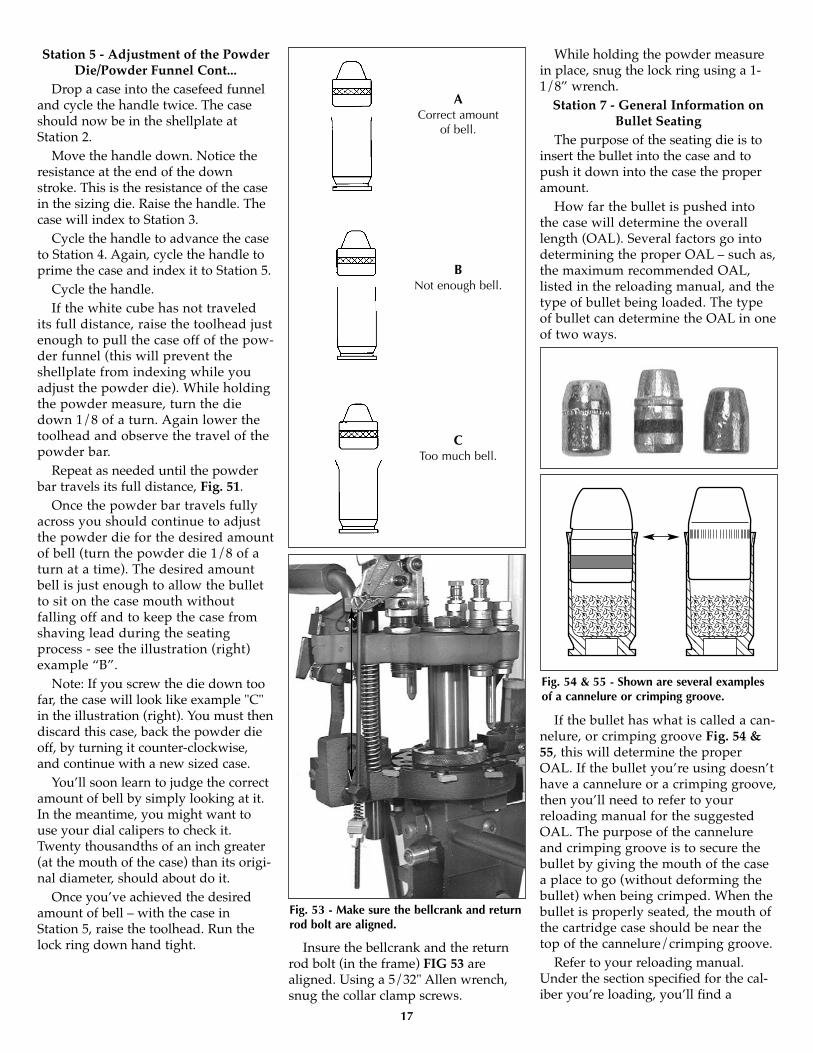
Station 7 - General Information onBullet Seating
The purpose of the seating die is toinsert the bullet into the case and topush it down into the case the properamount.
How far the bullet is pushed intothe case will determine the overalllength (OAL). Several factors go intodetermining the proper OAL – such as,the maximum recommended OAL,listed in the reloading manual, and thetype of bullet being loaded. The typeof bullet can determine the OAL in oneof two ways.
If the bullet has what is called a can-nelure, or crimping groove Fig. 54 &55, this will determine the properOAL. If the bullet you’re using doesn’thave a cannelure or a crimping groove,then you’ll need to refer to yourreloading manual for the suggestedOAL. The purpose of the cannelureand crimping groove is to secure thebullet by giving the mouth of the casea place to go (without deforming thebullet) when being crimped. When thebullet is properly seated, the mouth ofthe cartridge case should be near thetop of the cannelure/crimping groove.
Refer to your reloading manual.Under the section specified for the cal-iber you’re loading, you’ll find a
17
Fig. 54 & 55 - Shown are several examplesof a cannelure or crimping groove.
Fig. 53 - Make sure the bellcrank and returnrod bolt are aligned.
ACorrect amount
of bell.
BNot enough bell.
CToo much bell.
����������
����������
����������������������
����������
����������
����������������������

schematic of the cartridge. For example,.38 Special lists a maximum OAL of1.55" (Lyman Reloading Handbook). Ifyou’re seating the bullet to the can-nelure/crimping groove, the OALshould be well within the maximumOAL listed, however, use a set of dialcalipers to check it. (Dial calipers areavailable from Dillon Precision). If thebullet you’re using doesn’t have a can-nelure/crimping groove, refer to thespecific type of bullet you’re using inthe reloading manual. For example – ifyou’re loading a 158 gr. .38 Sp. JHPand it doesn’t have a cannelure/ crimp-ing groove, use the suggested OAL of1.480 (Lyman Reloading Handbook).
Station 7 - Installation andAdjustment of the Seating Die
Take the seating die from the die boxand screw it into Station 7. Screw thedie down until the bottom of the die isflush with the bottom of the toolhead.Note: At this point the die will not bescrewed down far enough to beginseating the bullet, but it will give you aplace to start.
Place a case (with a belled casemouth) into Station 7. Fig. 56
Place a bullet on the belled casemouth and lower the toolhead. Then,raise the toolhead just enough toinspect the bullet without indexing theshellplate. If the bullet is not seateddeep enough, screw the seating diedown 1/2 turn at a time. As a guide,one full turn moves the die down about70 thousandths of an inch, about thethickness of a nickel. Again, cycle themachine and inspect the seating depth.Repeat these steps as necessary untilthe correct overall length is achieved.Use a dial caliper or equivalent tomeasure the overall length of the car-tridge. Check the overall length of theround against the information in yourreloading manual.
Once you have obtained the properOAL, replace the cartridge into Station7 and lower the toolhead. Using a 1-1/8" wrench to turn the lock ring and a7/8" wrench to hold the die body, snugthe lock ring.
Note: If you ever load a cartridgethat you are unhappy with, you can usea Dillon bullet puller to reclaim yourcomponents.Station 8 - Installation and adjustment
of the Crimp DieScrew the crimp die into Station 8.
Screw it down until it is flush with thebottom of the toolhead. This is a goodstarting point for the crimp adjustment.
Place a cartridge with a properlyseated bullet into Station 8.
Lower the toolhead and continue toscrew the die down until it touches thecartridge. Fig. 57
Raise the toolhead and screw the diedown 1/8 of a turn, lower the toolhead.
Raise the toolhead half-way andinspect the cartridge. If the bell is stillpresent, or the desired amount of crimphas not been achieved, give the die a1/8 turn down and try again. Continuemaking small adjustments to yourcrimp die until the desired amount ofcrimp has been achieved.
Once the adjustment is complete,place the case back into Station 8 andlower the toolhead. Using a 1-1/8"wrench to turn the lock ring and a7/8" wrench to hold the die body,snug the lock ring.
Note: When adjusting the crimp dieit is important to know what to look for.Check that the crimp: Looks OK, allowsyour firearm to function consistentlyand the bullet feels tight in the case.
The drawing of case #3 (above) is adepiction of a case that has been overcrimped by adjusting the crimp diedown (clockwise) too far. Note the
18
Fig. 56 - Place the bullet on the casemouth at Station 7.
Fig. 57 - Cut away crimp die shows thearea being crimped while the case isbeing fully supported by the die body.
Please note that every die set includesseating stems to fit most common bullettypes. Select the appropriate seating stemfor the bullet type you are loading.
���������
��������������������������������
����������
����������
����������������������
����������
����������
321

defined line below the mouth of thecase and the bulge below the line. Thisis not a proper crimp. This line is thedirect result of the cartridge being overcrimped. A line like this will onlyappear if the crimp die is adjusteddown too far. Warning: Over crimp-ing .45ACP, .38 Super, 9mm, etc., canactually cause the bullet to be loosein the case.
Adjustments for calibers 9mm, .38 Sp.,.45 ACP and for hot loads that have
been fired many timesConfiguration 1
To begin, place a military case (sized,decapped and unswaged) into Station 3.
Screw the back-up rod (#12749*)down two turns into the toolhead(#20420). Pull the handle.
Using a wrench turn the back-up rod(#12749*) down until it hits the insidebottom of the case. Note: Do not forcethe expander as this will damage thecase and the shellplate. Now secure thelock ring (#20006*). Raise the handle.
Screw the eyebolt (#13245) all theway into the swager. Grease the clevispin (#13522) heavily.
Put the swager into position. Pushthe clevis pin through the connectingrod and eyebolt and secure with thehitch pin (#13840). Replace the swagecover (#13064).
With the military case still inStation 3, pull the operating handledown with your left hand. Now turnthe swager upward with your righthand until it meets resistance. Withyour left hand raise the operatinghandle about 10 inches. With yourright hand turn the swager up a 1/4turn. Cycle the handle down.
Raise the handle just enough toremove the case and inspect theprimer pocket to see the amount ofswaging being done. The swagershould leave a radiused entrance onthe primer pocket. Fig. 58
Turn the swager in, using 1/4 turnincrements until you achieve the prop-er swage. Secure the jam nut (#13682).Note: Do not over swage. This condi-tion will cause damage to theshellplate (#12600*).
When your swager is properlyadjusted you will feel resistance duringthe final 1/2" to 1" of the downwardstroke of the handle.
Adjustments for rifle calibersConfiguration 2
To begin, place a military case (sized,decapped and unswaged) into Station 3.
Remove the back-up rod (#12749*)from the back-up die (#12184).
With the operating handle in thedown position, screw the back-up dieinto Station 3 until the die comes intocontact with the shellplate. Now backthe die out one full turn and secure it inplace with the lock ring (#14067).
Leave the handle in the down posi-tion. With a wrench, screw the back-up rod into the back-up die. Turn theback-up rod down until it touches theinside bottom of the case. Note: Donot force the expander as this willdamage the case and the shellplate.Now secure the lock ring (#20006*).Raise the handle.
Screw the eyebolt (#13245) all theway into the swager. Grease the clevispin (#13522) heavily.
Put the swager into position. Pushthe clevis pin through the connectingrod and eyebolt and secure with thehitch pin (#13840). Replace the swagecover (#13064).
With the military case still in Station3, pull the operating handle downwith your left hand. Now turn theswager upward with your right handuntil it meets resistance.With your lefthand raise the operating handle about10 inches. With your right hand turnthe swager up a 1/4 turn. Cycle thehandle down.
Raise the handle just enough toremove the case and inspect theprimer pocket to see the amount ofswaging being done. The swagershould leave a radiused entrance onthe primer pocket. Fig. 58
Turn the swager in, using 1/4 turnincrements until you achieve the properswage. Secure the jam nut (#13682).Note: Do not over swage. This condi-
tion will cause damage to the shellplate(#12600*).
When your swager is properlyadjusted you will feel resistance duringthe final 1/2" to 1" of the downwardstroke of the handle.
RL1050 vs. Super 1050Not all parts are the same but some
are still interchangeable. We have madechanges to several parts used on theSuper 1050 that are not interchangeablewith the RL1050 machine.• The Super 1050 primer lever assem-
bly (#) has a longer arm to accommo-date the higher toolhead travel. Thisis not available for RL 1050machines. Primer feed body (#20773)will fit both machines but again theprimer lever assembly will not.
• The Super 1050 assembly does notinclude the ratchet cam, ratchetrestriction tab and related parts.
• The Super 1050 index lever has beenshortened considerably and will notindex properly on RL 1050 machines.
• The Super 1050 index roller haschanged in diameter and is much toolarge for the RL 1050.
• The Super 1050 mainshaft, main-shaft pivot pin, crankshaft assem-bly, and bearings are completelydifferent.
• The casefeed body has been modifiedto allow long cases to feed throughbut is interchangeable between theSuper 1050 and RL 1050 machines.
• Any RL 1050 toolhead assembly willfit the Super 1050 machine. You willneed to remove the ratchet cam fromthe toolhead and install a 1/8” thickwasher or spacer in its place. Thenreinstall the cam guide bolt.
• The toolhead spring and sleeve, as aset, are longer to accommodate theincreased toolhead travel on theSuper 1050 but they will work onthe RL 1050.
• Any RL 1050 shellplate will fit onthe Super 1050 with one exception.The #1 shellplate for .45 ACP hastight fitting pockets and may ormay not allow .308 Winchester casesto feed into the shellplate freely. Allnew #1 shellplates have a star nextto the number one to indicate therevised version.
• The Super 1050 indexer return spring
19
Fig. 58 - Note the difference between theswaged primer pocket (left) and theunswaged primer pocket (right).

has an additional bend in it but canbe used on both the Super 1050 andRL 1050 machines. NOTE: If you areusing an indexer return spring froman RL 1050 spare parts kit, you willneed to make an additional bend inthe spring before installing it on theSuper 1050.
• The RL 1050 spent primer cup hasbeen replaced with a larger, plasticspent primer cup and bracket. It isnot interchangeable.
Using RL 1050 toolheads anddies on the Super 1050...
If you want to interchange an RL1050 toolhead already set for a caliberyou want to load onto the Super 1050you will need to check for the followingclearances.
1. Remove the toolhead assemblyfrom the Super 1050.
2. Replace the shellplate with theshellplate for the caliber you intend toload with.
3. Remove the toolhead spring andset the toolhead onto the mainshaftwhile holding the handle at about mid-travel for proper alignment into theframe. Next, install the washer andtoolhead bolt.
4. Slowly lower the handle and lookto see if any die comes in contact withthe shellplate. Readjust dies as needed.
5. Place one unprimed case in theswage station and again slowly lowerthe handle. Readjust the expander andswage rod as needed.
6. Once you have reset the dies to themachine, remove the toolhead and rein-stall the toolhead spring and completethe rest of the conversion and set up toreload. Reinstall the toolhead.
Trouble Shooting .308 Winchester and related calibers
with similar case length (.243 and/or.22-250) also lend themselves to reload-ing on this new machine. No specialchanges are necessary to the die set.
Hard or Incomplete Indexing1.) Wrong size locator buttons(#20637*).
2.) Index pawl bent or worn (#13705).
3.) Shellplate lock ring adjusted tootightly (#20311).
4.) Dirt under the shellplate (#12600*).
5.) Bent or broken shellplate (#12600*).
6.) Ejector tab (#13189) interfering withthe shellplate - see above photo.
Station 1: Case Insertion Problems1.) Wrong size case insert plunger(#13073*).
2.) Wrong case insert adapter (#13654*).
3.) Shellplate lock ring not adjustedtight enough.
4.) Dirt in the shellplate (#12600*) pock-ets or damaged shellplate.
5.) Handle being moved too rapidly onupstroke.
6.) Bent or broken roller bolt (#13333).
7.) Dirt or media in casefeed track.
Station 2: Resizing andDecapping Problems
With .30-06 and .270 calibers it isimportant to note that the seater andcrimp dies must be shortened for clear-ance reasons. They are available andare included with the respective con-version kits.
1.) Crushed cases:a.) Shellplate lock ring too loose or
too tight. b.) Not enough radius on the die.
Use Dillon dies whenever possible.c.) Wrong size or missing locator but-
tons.
2.) Bending or breaking decapping pins:a.) Wrong shellplate (#12600*).b.) Slightly bent decapping assembly
or pin.c.) Berdan primed cases.
d.) Dirt in shellplate pockets.e.) Handle being moved too rapidly
on the down stroke.f.) Rocks or other foreign objects in
cases.Station 3: Primer Pocket Swaging
Problems1.) Primers smearing or crushing:
a.) Swage back-up rod not down farenough (#13332 or #13348).
b.) Swage rod not adjusted highenough (#20314 - large or #20313 -small).
Station 4: Priming Problems
The above photo shows the rockerarm set screw (#13226) being adjusted.The Super 1050 comes from the factorywith this set screw properly adjusted,but over time it can move. When therocker arm set screw is out of adjust-ment, it can dent primers and/or causethe primer slide to stick. When proper-ly adjusted, the primer punch (#12849large - #13307 small) will be flush withthe platform surface – see arrow above.1.) Crushed primers:
a.) Swage rod (#20314 - large or#20313 - small) not adjusted correctly,dirty or worn out.
b.) Dirt in the shellplate (#12600*).c.) Ringed primer. When a spent
primer has been pierced by the decap-ping pin leaving a ring of metal fromthe primer in the pocket.
d.) Primer station locator button(#20637*) not adjusted correctly.
e.) Worn primer punch (#12849).f.) The bench that the machine is
mounted on is not rigid enough. Thiscan be corrected by affixing a board toboth the wall and your bench.
g.) Hot-loaded ammo that has beenfired several times and the base of the
20
When reinstalling the ejector tab (#13189) itis vital that it is not set too low or it willinterfere with the shellplate.
primer punch

case has been flattened out.
2.) High primers:a.) Adjust the primer push rod
(#12819).b.) On .223 cases the swage back-up
rod (#13332) is down too far, slightlycollapsing the primer pocket and notallowing the primer to seat fully.
c.) Loose shellplate (#12600*).d.) Erratic handle motion.e.) Do not remove the rubber piece
on the primer slide.
3.) Smeared primers - see Station 3:Primer Pocket Swaging - item 1
4.) Locator tab:a.) When adjusting the priming sta-
tion locator tab, it should be set asclose to the case as possible withouttouching it. Be sure the cases in theshellplate rotate freely past the tab.Change primer magazine tips every20,000 rounds. Note: Move the handledown, bringing the toolhead down.Move the locator tab in to the case inthe priming station.
Station 5. Powder and Case MouthBelling Problems
1.) Crushing cases:a.) Wrong size or missing locator
buttons.
2.) Spilling powder:a.) Slamming or going too fast with
the operating handle (#12727).b.) Stick or pencil-lead type pow-
ders bridging on the case mouth in thepowder funnel (#13005). See conver-sion chart.
c.) Check powder bar adjustment.
3.) Erratic belling:a.) Variation in case length. Divide
cases by brand.b.) Handle not moving all the way
down on each stroke. Note: Try settinga bullet on the case mouth in Station 6.
4.) Erratic powder charges:a.) Powder bar not moving full
length of its travel. Turn the powder diedown until it does.
Station 7: Bullet Seating Problems1.) Erratic seating depth of the bullet:
a.) Build up of lead shaving and/orlube in the seater or crimp dies.
b.) Bullets having erratic dimension
(length and/or the ogive).c.) Use the proper seating stem for
the type of bullet being used.d.) Variations in case types and/or
lots – sort brass.e.) Refer to a loading manual for
proper loaded length (OAL) and addi-tional information.
Station 8: Crimping Problems1.) Erratic crimping:
a.) Length of cartridge cases erratic,probably due to mixed brands of brass.
b.) Worn out or improperly madedie, use Dillon dies whenever possible.
2.) Loose bullet:a.) Too much taper crimp. Note, this
condition also ruins accuracy.b. Wrong expander (#12749*).c.) Thin cases.
MaintenanceLoctite
Loctite should be used followingadjustments to or replacement of allthreaded screws. Please note thatLoctite should be applied to threadedportions only and should be of a non-permanent type. Blue Loctite #242 isrecommended.
SwageClean the swage by pulling the oper-
ating handle down and use a smallbrush to clean the tip. Every 10,000rounds, remove the swage rod (#20314- large or #20313 - small). and clean,lightly grease and replace. Note: Do notgrease the tip of the swage where itcontacts the primer pocket.
21
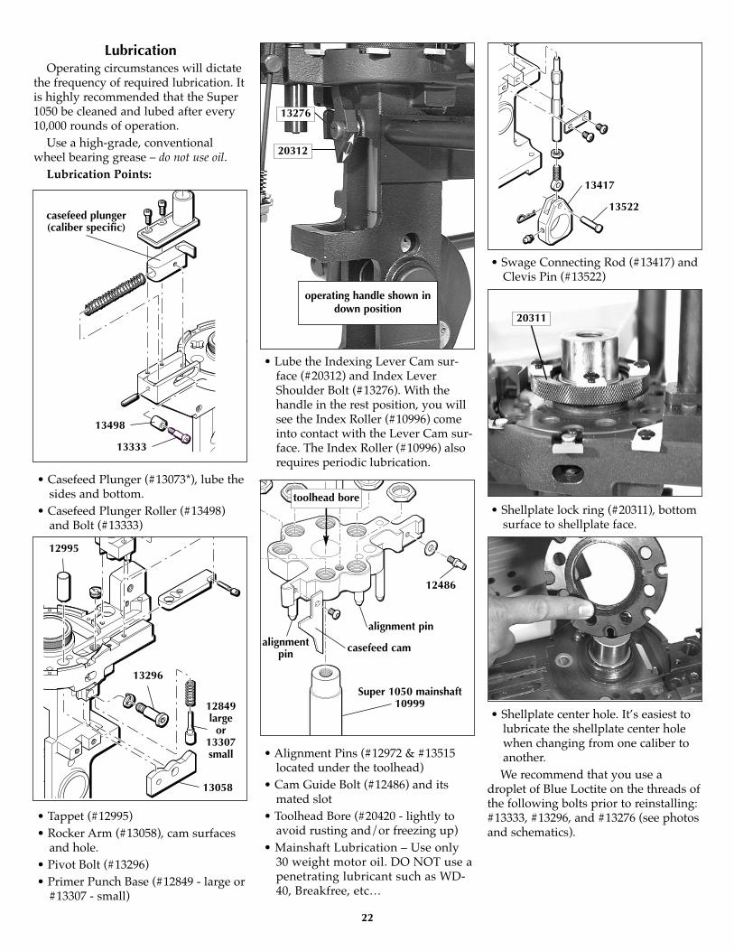
LubricationOperating circumstances will dictate
the frequency of required lubrication. Itis highly recommended that the Super1050 be cleaned and lubed after every10,000 rounds of operation.
Use a high-grade, conventionalwheel bearing grease – do not use oil.
Lubrication Points:
• Casefeed Plunger (#13073*), lube thesides and bottom.
• Casefeed Plunger Roller (#13498)and Bolt (#13333)
• Tappet (#12995)• Rocker Arm (#13058), cam surfaces
and hole.• Pivot Bolt (#13296)• Primer Punch Base (#12849 - large or
#13307 - small)
• Lube the Indexing Lever Cam sur-face (#20312) and Index LeverShoulder Bolt (#13276). With thehandle in the rest position, you willsee the Index Roller (#10996) comeinto contact with the Lever Cam sur-face. The Index Roller (#10996) alsorequires periodic lubrication.
• Alignment Pins (#12972 & #13515located under the toolhead)
• Cam Guide Bolt (#12486) and itsmated slot
• Toolhead Bore (#20420 - lightly toavoid rusting and/or freezing up)
• Mainshaft Lubrication – Use only30 weight motor oil. DO NOT use apenetrating lubricant such as WD-40, Breakfree, etc…
• Swage Connecting Rod (#13417) andClevis Pin (#13522)
• Shellplate lock ring (#20311), bottomsurface to shellplate face.
• Shellplate center hole. It’s easiest tolubricate the shellplate center holewhen changing from one caliber toanother.We recommend that you use a
droplet of Blue Loctite on the threads ofthe following bolts prior to reinstalling:#13333, #13296, and #13276 (see photosand schematics).
22
casefeed plunger(caliber specific)
13498
13333
12995
13296
13058
12849large
or13307small
12486
alignment pin
Super 1050 mainshaft10999
toolhead bore
alignmentpin casefeed cam
13417
13522
13276
20312
operating handle shown indown position
20311

23
10999
11000
11008
10994
11008
13685
11010
10996
11002
11009
Lube Points for the Super 1050Crank Assembly
With the handle in the rest position,on the left side of the machine, use agrease syringe to lube the bearing pin(#11009) located in the link arm(#11002). Then, cycle the handle downto the bottom stop.
Again, using the grease syringe,lube the mainshaft pivot pin (#10994)on the left side of the machine via theaccess hole located 1.2" above the car-rier cap (#11010).
Use 30 weight motor oil on the main-shaft (#10999).
Towards the back of the machine,lube the indexing lever cam surface(#20312) and index lever shoulderbolt (#13276).
When it is time to lube the rollerbearings (#11008) in the frame andcrankshaft, first remove the swage rodassembly, swage connecting rod, andoperating handle. On the left side of themachine, use a 5/32" Allen wrench toremove the screw (#13685). Slide thecarrier cap (#11010) out of its bore andlube the left-hand side roller bearing(#11008) and carrier cap. Next, slide thecrankshaft (#11000) out of the frame
from the right side of the machine BUTNO MORE THAN 3/4". Using a greasesyringe, dispense some grease onto theright-hand side roller bearing (#11008).Next, lube the crankshaft surface(#11000). Then, reinsert the crankshaftfully into the frame. Reinstall the carriercap (#11010). Blue Loctite must be usedon the threads before installation, tight-en. Finally, reassemble the swage com-ponent and operating handle back ontothe frame. Lube the swage connectingrod (#13417) and clevis pin (#13522).

24
RL 1050 - Caliber Conversion Chart
20477 – .38/.357 Conversion12704 #2 Shellplate14062 #2 Locator Buttons (6)13137 .38/.357 cal. Expander – D13802 Adapter – Orange13098 Casefeed Plunger – Medium17384 Blue Locator Tab – Short (1)13569 Blue Locator Tab (5)14067 Die Lock Ring13005 Powder Activator – Pistol20478 – .41 Mag Conversion11856 #6 Shellplate13930 #1 Locator Buttons (6)12882 .41 cal. Expander – H13654 Adapter – Yellow13073 Casefeed Plunger – Large17384 Blue Locator Tab – Short (1)13569 Blue Locator Tab (5)14067 Die Lock Ring13005 Powder Activator – Pistol20479 – .44 Spl/MagConversion12600 #4 Shellplate14047 #4 Locator Buttons (6)12628 .44 cal. Expander – G13654 Adapter – Yellow13073 Casefeed Plunger – Large17384 Blue Locator Tab – Short (1)13569 Blue Locator Tab (5)14067 Die Lock Ring13005 Powder Activator – Pistol20480 – .45 ACP Conversion12999 #1 Shellplate13930 #1 Locator Buttons (6)12749 .45 cal. Expander – E13872 Adapter – Red13073 Casefeed Plunger – Large17384 Blue Locator Tab – Short (1)13569 Blue Locator Tab (5)14067 Die Lock Ring13005 Powder Activator – Pistol20481 – .45 LC Conversion11235 #C Shellplate14047 #4 Locator Buttons (6)12749 .45 cal. Expander – E13654 Adapter – Yellow13073 Casefeed Plunger – Large17384 Blue Locator Tab – Short (1)13569 Blue Locator Tab (5)14067 Die Lock Ring13005 Powder Activator – Pistol
20482 – 9mm Conversion12938 #5 Shellplate14060 #3 Locator Buttons (6)12833 9mm cal. Expander – F13878 Adapter – Green13306 Casefeed Plunger – Small17384 Blue Locator Tab – Short (1)13569 Blue Locator Tab (5)14067 Die Lock Ring13005 Powder Activator – Pistol20483 – .380 Auto Conversion12441 #3 Shellplate14060 #3 Locator Buttons (6)13285 .380 cal. Expander – F13810 Adapter – White12964 Casefeed Plunger – Small .38017384 Blue Locator Tab – Short (1)13569 Blue Locator Tab (5)14067 Die Lock Ring13419 1/4–28 Jam Nut13017 Swage Back-up Rod – Large12184 Swage Die13483 9/16-18 Lock Nut13005 Powder Activator – Pistol20484 – .38 Super Conversion12938 #5 Shellplate14060 #3 Locator Buttons (6)12833 9mm cal. Expander – F13878 Adapter – Green13306 Casefeed Plunger – Small17384 Blue Locator Tab – Short (1)13569 Blue Locator Tab (5)14067 Die Lock Ring13005 Powder Activator – Pistol20788 – 10mm AutoConversion12940 #W Shellplate14062 #2 Locator Buttons (6)12912 10mm cal. Expander – W13872 Adapter – Red13098 Casefeed Plunger – Medium17384 Blue Locator Tab – Short (1)13569 Blue Locator Tab (5)14067 Die Lock Ring13005 Powder Activator – Pistol20485 – .223 Conversion12441 #3 Shellplate14060 #3 Locator Buttons (6)13332 Back-up/Expander .22313426 Powder Funnel – A12146 Adapter (pinned) – White, Long13306 Casefeed Plunger – Small17384 Blue Locator Tab – Short (1)13569 Blue Locator Tab (5)14067 Die Lock Ring12184 Swage Die13483 9/16-18 Lock Nut
20626 – .30 CarbineConversion12655 #8 Shellplate14048 #8 Locator Buttons (6)12748 .30M1 cal. Expander – C13564 Powder Funnel C12641 Adapter – White, Slotted13306 Casefeed Plunger – Small17384 Blue Locator Tab – Short (1)13569 Blue Locator Tab (5)14067 Die Lock Ring20631 – 7.62x39 Conversion11925 #A Shellplate14062 #2 Locator Buttons (6)13348 Back-up/Expander 7.62x3913015 Powder Funnel AK12943 Adapter13098 Casefeed Plunger – Medium13703 Casefeed Spacer17384 Blue Locator Tab – Short (1)13569 Blue Locator Tab (5)12184 Swage Die13483 9/16-18 Lock Nut14067 Die Lock Ring20634 – .32 S&W Long/H&RMagnum Conversion12107 #D Shellplate14060 #3 Locator Buttons (6)12780 .32 cal. Expander – S12845 Powder Funnel – S13878 Adapter – Green13306 Casefeed Plunger – Small17384 Blue Locator Tab – Short (1)13569 Blue Locator Tab (5)14067 Die Lock Ring21525 – 9x25 DillonConversion12940 #W Shellplate14062 #2 Locator Buttons (6)12833 9mm cal. Expander – F13872 Adapter – Red13098 Casefeed Plunger – Medium17384 Blue Locator Tab – Short (1)13569 Blue Locator Tab (5)14067 Die Lock Ring13005 Powder Activator – Pistol20545 – .40 S&W Conversion12940 #W Shellplate14062 #2 Locator Buttons (6)12912 10mm cal. Expander – W13878 Adapter – Green13098 Casefeed Plunger – Medium17384 Blue Locator Tab – Short (1)13569 Blue Locator Tab (5)14067 Die Lock Ring13005 Powder Activator – Pistol
25
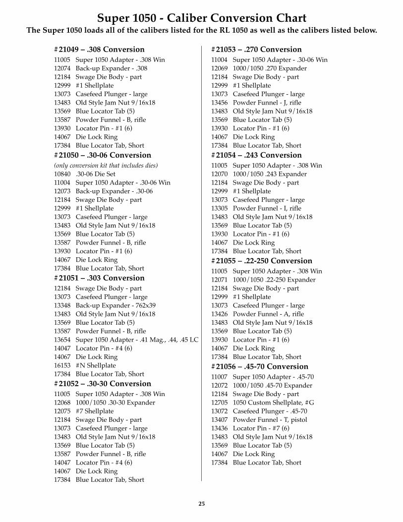
#21049 – .308 Conversion11005 Super 1050 Adapter - .308 Win12074 Back-up Expander - .30812184 Swage Die Body - part12999 #1 Shellplate13073 Casefeed Plunger - large13483 Old Style Jam Nut 9/16x1813569 Blue Locator Tab (5)13587 Powder Funnel - B, rifle13930 Locator Pin - #1 (6)14067 Die Lock Ring17384 Blue Locator Tab, Short
#21050 – .30-06 Conversion(only conversion kit that includes dies)10840 .30-06 Die Set11004 Super 1050 Adapter - .30-06 Win12073 Back-up Expander - .30-0612184 Swage Die Body - part12999 #1 Shellplate13073 Casefeed Plunger - large13483 Old Style Jam Nut 9/16x1813569 Blue Locator Tab (5)13587 Powder Funnel - B, rifle13930 Locator Pin - #1 (6)14067 Die Lock Ring17384 Blue Locator Tab, Short
#21051 – .303 Conversion12184 Swage Die Body - part13073 Casefeed Plunger - large13348 Back-up Expander - 762x3913483 Old Style Jam Nut 9/16x1813569 Blue Locator Tab (5)13587 Powder Funnel - B, rifle13654 Super 1050 Adapter - .41 Mag., .44, .45 LC14047 Locator Pin - #4 (6)14067 Die Lock Ring16153 #N Shellplate17384 Blue Locator Tab, Short
#21052 – .30-30 Conversion11005 Super 1050 Adapter - .308 Win12068 1000/1050 .30-30 Expander12075 #7 Shellplate12184 Swage Die Body - part13073 Casefeed Plunger - large13483 Old Style Jam Nut 9/16x1813569 Blue Locator Tab (5)13587 Powder Funnel - B, rifle14047 Locator Pin - #4 (6)14067 Die Lock Ring17384 Blue Locator Tab, Short
#21053 – .270 Conversion11004 Super 1050 Adapter - .30-06 Win12069 1000/1050 .270 Expander12184 Swage Die Body - part12999 #1 Shellplate13073 Casefeed Plunger - large13456 Powder Funnel - J, rifle13483 Old Style Jam Nut 9/16x1813569 Blue Locator Tab (5)13930 Locator Pin - #1 (6)14067 Die Lock Ring17384 Blue Locator Tab, Short
#21054 – .243 Conversion11005 Super 1050 Adapter - .308 Win12070 1000/1050 .243 Expander12184 Swage Die Body - part12999 #1 Shellplate13073 Casefeed Plunger - large13305 Powder Funnel - I, rifle13483 Old Style Jam Nut 9/16x1813569 Blue Locator Tab (5)13930 Locator Pin - #1 (6)14067 Die Lock Ring17384 Blue Locator Tab, Short
#21055 – .22-250 Conversion11005 Super 1050 Adapter - .308 Win12071 1000/1050 .22-250 Expander12184 Swage Die Body - part12999 #1 Shellplate13073 Casefeed Plunger - large13426 Powder Funnel - A, rifle13483 Old Style Jam Nut 9/16x1813569 Blue Locator Tab (5)13930 Locator Pin - #1 (6)14067 Die Lock Ring17384 Blue Locator Tab, Short
#21056 – .45-70 Conversion11007 Super 1050 Adapter - .45-7012072 1000/1050 .45-70 Expander12184 Swage Die Body - part12705 1050 Custom Shellplate, #G13072 Casefeed Plunger - .45-7013407 Powder Funnel - T, pistol13436 Locator Pin - #7 (6)13483 Old Style Jam Nut 9/16x1813569 Blue Locator Tab (5)14067 Die Lock Ring17384 Blue Locator Tab, Short
Super 1050 - Caliber Conversion ChartThe Super 1050 loads all of the calibers listed for the RL 1050 as well as the calibers listed below.

26
Super 1050 Parts Listing
Part # Description10991 Bin Support Bracket10992 Inside Frame Stop10993 Spent Primer Cup Bracket10994 .560 dia. Mainshaft Pin10995 Index Lever10996 Index Roller10997 Super 1050 Frame10999 Mainshaft11000 Crank Shaft11001 Crank Arm11002 Link Arm11003 Lever Arm11006 Super 1050 Modified
Casefeed Housing11008 BH-1610 Roller Bearing11009 1.00 dia. Pin11010 Carrier Cap11011 Super 1050 Manual12144 Bullet Bin Bracket12184 Swage Die Body – Part12260 1050 Box For Shipping12486 Cam Guide Bolt 1/4x2012572 Toolhead Spring12819 Primer System Push Rod12930 Primer Station Retain Tab12972 Toolhead Alignment Rod12995 Primer System Tappet13001 New Lever Arm Bracket13058 Primer System Rocker Arm13064 Swage Cover 105013073 Casefeed Plunger – Large13089 Return Rod Eye Bolt13091 Alignment Bushing – New13098 Casefeed Plunger – Medium13108 Primer Slide Stop “B”13161 Casefeed Cam105013189 1050 Ejector Tab13205 Post Bolts13226 Rocker Arm Set Screw13238 Bin Bracket13244 Crank Retaining Pin (2)13245 Primer Swage Adjustment Bolt13262 7/32” Hex Wrench (Short)13271 Post Stud13276 Index Lever Shoulder Bolt13296 Primer System Rocker Bolt13306 Casefeed Plunger – Small13333 Locator Tab Bolt13335 Spring Bushing13342 Toolhead Bolt13363 Primer Magazine Socket Bolt13377 Bin Bracket Mount Screw13417 Swage Connecting Rod13419 Swage Rod Lock Nut13426 Powder Funnel A – Rifle13432 Crank Handle Lock Screw13435 1/4” Hex Wrench
Part # Description13449 Toolhead Washer13475 Journal Key 105013483 Old Style Jam Nut 9/16x1813484 1050 Cartridge Bin13495 Lower Cord Clamp13498 Plunger Roller 105013502 Clamp Retaining Screw13508 Index Ball 105013515 Slide Alignment Pin13522 Clevis Pin13525 Index Ball Spring 105013534 Casefeed Adapter Housing13561 Lock Ring Insert13567 Casefeed Plunger Spring13581 Grease Zerts13593 5/32” Hex Wrench13607 Rocker Bolt Lock Washer13611 Casefeed Post Warning Label13624 Index Pawl Spring13644 Small Powder Bar Spacer13650 Spent Primer Cup13655 5/16 Washer13664 5/16-18 Nut13682 Swage Lock Nut 105013685 1/4-20x1/2 Bracket Bolt13696 3 Packing Foam Pieces13701 Index Pawl Pin 3/813705 1050 Index Pawl13728 1/8” Hex Wrench13738 #10 Washer for Roller13746 Actuating Lever Cotter Pin13756 1050 Bullet Bin13761 Casefeed Tube 105013793 Collar Roller13799 Strip Nut13801 Tinnerman Insert13813 Clutch Spring Washer13815 Adapter Housing Screw13818 Powder Bar Insert – Small13827 3/16” Hex Wrench13840 Hair Pin Cotter13844 Short Lever Spring13845 Body Collar Sleeve13848 Bellcrank Bushing13853 Powder Bar Insert – Large13858 Primer Punch Spring 105013859 Casefeed Tube Clip13871 Bellcrank Cube13882 Powder Measure Lid13886 3/32” Hex Wrench13888 E-Clip13893 Powder Bar Post – Large13895 10-24 x 3/8” BH Screw (6)13896 1/4-20 3/8 BH – Ejector Tab Screw13904 Bellcrank Bolt13921 Powder Bar Spacer Plug13929 Return Rod Clip
Part # Description13939 Body Collar Clamp – Part13943 Powder Bar Adjustment Screw13944 Indexer Return Spring13951 Powder Bar Post – Small13955 Lower Plate Screw13957 Magazine Shield Cap 105013958 Powder Bar Bolt Washer13960 Powder Bar Return Rod – Part13964 10-24x1/4 BHCS for Index Roller13972 3/16 Roll Pin14003 Magazine Orifice – Large – Red14023 10-24 5/8 Buttonhead Screw14024 Magazine Orifice – Small – Blue14033 Return Rod Spring14036 Old Powder Bar Return Spring 14037 10-24x3/4 SHCS –
Collar Clamp Screw (2)14067 Die Lock ring14202 Powder Measure Tube Screw14517 Swage Station Bushing14808 Collar Roller Bushing14990 Slide Roll Pin Sleeve16699 Spent Primer Cup17069 Snap Ring17141 1/4” Hardened Washer17604 Bracket Pivot Pin17808 Casefeed Bowl Insert20062 Small Powder Bar Assembly20063 Large Powder Bar Assembly20311 1050 Lock Ring Assembly20312 1050 Index Lever Assembly20313 Swage Rod 1050 – Small20314 Swage Rod 1050 – Large20317 1050 Primer Slide – Small20318 1050 Primer Slide – Large20320 Powder Die20322 Casefeed Assembly 1050 –
Large Pistol20324 Casefeed Assembly 1050 –
Small Rifle20341 1050 Bushing Driver20419 1050 Primer System – Small20420 1050 Toolhead Assembly20421 Auto Powder System20476 1050 Primer System – Large20488 1050 Primer Arm/Cam – Assembly20635 Ratchet Detent Assembly20641 Casefeed Mounting Post – Assembly20773 Primer Feed Body/Shield20785 Powder Measure Body21072 Casefeed Plate – Large Pistol21073 Casefeed Plate – Small Pistol21074 Casefeed Plate – Small Rifle21079 Casefeed Assembly 1050 –
Small Pistol21275 Body Collar – Complete21530 Floating Decap Assembly

27
Super 1050 Upper Machine Assembly
#17071 – Handle Assembly
17918
12727
11000
13432
17069
11000
#20420 – Toolhead Assembly13342
13449
20420
13957
20773
13955
13108
13276
13944
12930
13895
13650
13896
10993
13896 13189
13525
13508
13226
13089
13425
2063513335
12572
13895
13561
*20637
See page 29 formore detail.
13342
12819
13005 - 13015refer to the caliberconversion chart
20320
14067
SeatingDie
SizingDie
14067
10999
13161 13896
17141
12486
20420
13449Crimp
Die
20312assembly
20311assembly
Shellplate – caliber specific,
refer to thecaliber conver-
sion chart
20317 – small20318 – large
Expander –refer to the
caliberconversion
chart

28
10999
11000
1347511008
11001
11008
1324411009
10994
13244
11002
11008
13685
11010
1389513738
10996
14517
20313 - small assembly20314 - large assembly
13064
1389613682
1324513417
13581
13840
13522
See page 31 – CasefeedFrame Assembly
SeeItem Aabove
Super 1050 Lower Machine Assembly
Item A – Swage Rod AssemblyLower Machine AssemblyPart # Description10994 Mainshaft Pivot Pin - .560” dia.10996 Index Roller10999 Super 1050 Mainshaft11000 Crankshaft11001 Crankarm11002 Link Arm11008 BH-1610 Roller Bearing (3)11009 Pin - 1” dia.11010 Carrier Cap13244 Crank Retaining Ring (2)13475 Journal Key13685 1/4-20x5/8 BHCS13738 #10 Washer13895 10-24x3/8 BHCS
Item A – Swage Rod AssemblyPart # Description13064 Swage Cover 105013417 Swage Connecting Rod13522 Clevis Pin13581 Grease Zerts13840 Hair Pin Cotter13896 1/4-20 3/8 BH Ejector Tab Screw14517 Swage Station Bushing20313 Swage Rod Assembly – Small:
13127 Swage Rod (1050) – Small13245 Primer Swage Adjustment Bolt13682 Swage Lock Nut 1050
20314 Swage Rod Assembly – Large:13245 Primer Swage Adjustment Bolt13364 Swage Rod (1050) – Large13682 Swage Lock Nut 1050
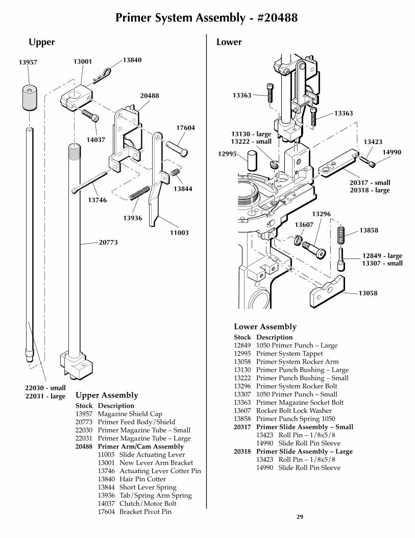
29
����
Primer System Assembly - #20488
Upper Lower
13957 13840
14037
13001
20488
11003
17604
13844
13936
13746
20773
13363
13363
12995
13130 - large13222 - small 13423
14990
13858
13058
13607
13296
12849 - large13307 - small
20317 - small20318 - large
22030 - small22031 - large Upper Assembly
Stock Description13957 Magazine Shield Cap20773 Primer Feed Body/Shield22030 Primer Magazine Tube – Small22031 Primer Magazine Tube – Large20488 Primer Arm/Cam Assembly
11003 Slide Actuating Lever13001 New Lever Arm Bracket13746 Actuating Lever Cotter Pin13840 Hair Pin Cotter13844 Short Lever Spring13936 Tab/Spring Arm Spring14037 Clutch/Motor Bolt17604 Bracket Pivot Pin
Lower AssemblyStock Description12849 1050 Primer Punch – Large12995 Primer System Tappet13058 Primer System Rocker Arm13130 Primer Punch Bushing – Large13222 Primer Punch Bushing – Small13296 Primer System Rocker Bolt13307 1050 Primer Punch – Small13363 Primer Magazine Socket Bolt13607 Rocker Bolt Lock Washer13858 Primer Punch Spring 105020317 Primer Slide Assembly – Small
13423 Roll Pin – 1/8x5/814990 Slide Roll Pin Sleeve
20318 Primer Slide Assembly – Large13423 Roll Pin – 1/8x5/814990 Slide Roll Pin Sleeve

30
Super 1050 Casefeeder Assembly
HIGH
OFF
LO
13400
17808
13494
13859
1381213540
1376113756
20641
13539
13205
13484
1337713685
12144
13655
13238See
Page 31Item A
13271
1365513495
Stock # Description12144 Bullet Bin Bracket13205 Post Bolts13238 Bin Bracket13271 Post Stud13377 Bin Bracket Mount Screw13400 Casefeed Bowl 105013473 Casefeed Motor – 4 RPM
(Not Shown)13484 1050 Cartridge Bin13494 Casefeed Funnel13495 Lower Cord Clamp13502 Clamp Retaining Screw13539 Casefeed Cord Set13540 Casefeed Motor Cover13655 5/16 Washer13688 Casefeed Funnel Baffle
(9mm/.380/.38 Sup. Not Shown)13756 Bullet Bin13761 Casefeed Tube 105013779 Micro-Switch (Not Shown)13812 Lighted Power Switch13859 Casefeed Tube Clip13895 10-24 BH Screw (Not Shown)13954 Micro-Switch Mount Screw
(Not Shown)14022 Casefeed Motor Roll Pin
(Not Shown)14023 10-24 5/8 Buttonhead Screw
(Not Shown)14026 8-32x1/2 Bowl/Motor Screw
(Not Shown)17808 Casefeed Bowl Insert 20322 Casefeed Assembly 1050
(Large Pistol)20324 Casefeed Assembly 1050
(Small Rifle)20641 Casefeed Mounting Post
Assembly21079 Casefeed Assembly 1050
(Small Pistol)

31
Super 1050 Casefeed Sub Assemblies Powder Measure Assembly - #22221
Casefeeder ClutchAssemblyStock # Description13632 Upper Clutch13655 5/16 Washer13703 Spacer (.41, .44, .45LC,
.357, .30 Carbine)13732 Clutch/Motor Bolt13736 Lower Clutch13813 Clutch Spring Washer21072 Casefeed Plate
(Large Pistol)21073 Casefeed Plate
(Small Pistol)21074 Casefeed Plate
(Small Rifle)
Item A – CasefeedFrame AssemblyStock # Description13333 Bolt (Locator Tab)13498 Plunger Roller13534 Adapter Housing13567 Casefeed Plunger Spring13815 Adapter Housing Screw13972 3/16 Roll Pin
* Indicates a caliber specific part – see the caliber conversioncharts on pages 24 & 25 for the caliber you are loading for.
21072
13732
13655 (4)
1381313632
13703
13736
Adapter – refer to the caliberconversion chart
Casefeed Plungerrefer to the cal-iber conversion
chart
13815
138821395113644
13943
20062
1389321353
20785
14202
16340
13940
13793
14808
13845
13089
1403313799
13801
20320
*13005*13426
13960
14023
14037
13939
14202
20063
9703413871
14041
1384813904
13929
13534
13567
13972
13498
13333
2078013921
frame
Stock # Description*13005 Powder Activator, Pistol13089 Return Rod Eye Bolt*13426 Powder Funnel “A”, Rifle13644 Small Powder Bar Spacer13793 Collar Roller13799 Blue Strip Nut13801 Tinnerman Insert13818 Powder Bar Insert, Small13845 Collar Sleeve13848 Bellcrank Bushing13853 Powder Bar Insert, Large13871 Bellcrank Cube13882 Powder Measure Lid13893 Powder Bar Post, Large13904 Bellcrank Bolt13921 Powder Measure Plug13929 Return Rod Clip13939 Collar Clamp13940 Body Collar Housing – Part
Stock # Description13943 Powder Bar Adjust. Screw13951 Powder Bar Post, Small13958 Powder Bar Bolt Washer13960 Powder Bar Return Rod –
Part14023 8-32x3/4 BH Screw14033 Return Rod Spring14037 Collar Clamp Screw14041 Bowed Washer14202 Powder Measure Tube Screw14808 Collar Roller Bushing16340 10-32 Nylon Lock Nut20062 Powder Bar, Small20063 Powder Bar, Large20320 Powder Die20780 Powder Bar, Extra Small20785 Powder Measure Body21275 Body Collar – Complete21353 Powder Bar, Magnum97034 Slotted Bellcrank & Cube

Dillon Precision Products, Inc.8009 E. Dillon’s Way • Scottsdale, AZ 85260
(480) 948-8009 • FAX (480) 998-2786
Web Site: www.dillonprecision.comE-mail: [email protected]
Technical Support & Customer Service(800) 223-4570
On the cover…The Super 1050 is pictured with optional accessories:Powder Check System #21044Low Powder Sensor #16306Bullet Tray #22215
Other accessories available for the Super 1050 include:Machine Cover #13239Maintenance Kit & Spare Parts Kit #97018
The Blue Press, Dillon’s monthly catalog, has a complete listing of accessories available for all machines.
For a free issue of the Blue Press, call our customer service department at: 1-800-223-4570