110 - OPITECnbg-web01.opitec.com/img/110/017/110017be.pdf · · 2013-09-13110.017 Please Note The...
22
1 E110017#1 A Basic Electronic Circuit Guide 110.017 Please Note The OPITEC range of projects is not intended as play toys for young children.They are teaching aids for young people learning the skills of Craft, Design and Technolo- gy.These projects should only be underta- ken and tested with the guidance of a fully qualified adult. The finished projects are not suitable to give to children under 3 years old. Some parts can be swallo- wed. Dan- ger of suffocation!
Transcript of 110 - OPITECnbg-web01.opitec.com/img/110/017/110017be.pdf · · 2013-09-13110.017 Please Note The...

1E110017#1
A B a s i c E l e c t r o n i c C i r c u i t G u i d e
1 1 0 . 0 1 7
Please NoteThe OPITEC range of projects is not intended as play
toys for young children.They are teaching aids for young people learning the skills of Craft, Design and Technolo- gy.These projects should only be underta-ken and tested with the guidance of a fully qualified
adult. The finished projects are not suitable to give to children under 3 years old. Some parts can be swallo-
wed. Dan- ger of suffocation!
2 E110017#1
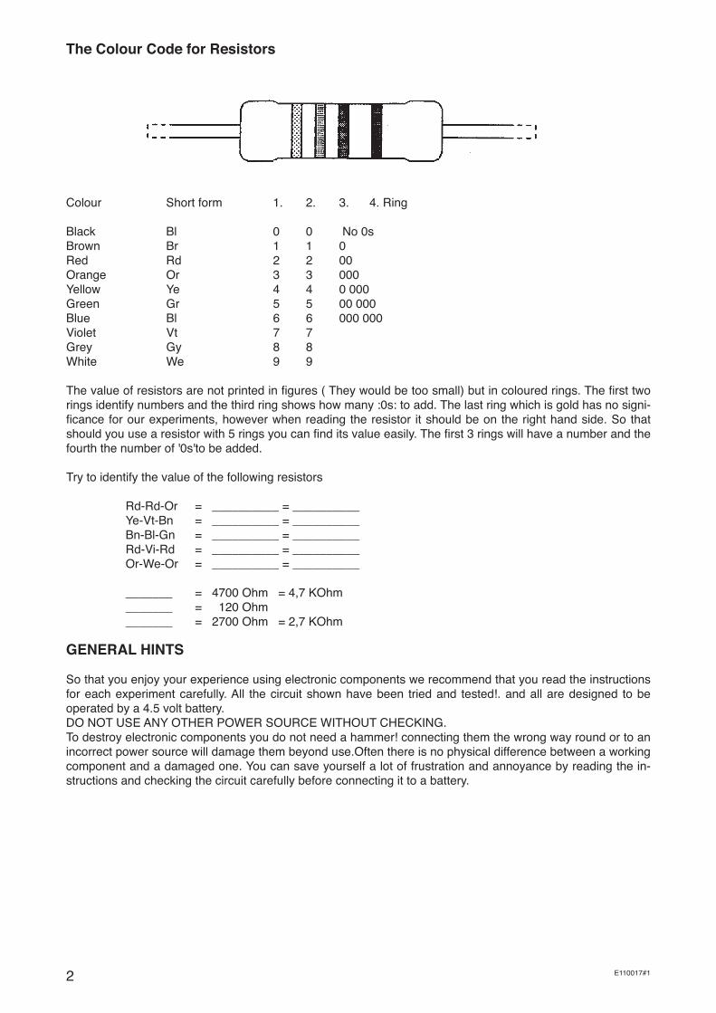
The Colour Code for Resistors
Colour Short form 1. 2. 3. 4. Ring
Black Bl 0 0 No 0sBrown Br 1 1 0Red Rd 2 2 00Orange Or 3 3 000Yellow Ye 4 4 0 000Green Gr 5 5 00 000Blue Bl 6 6 000 000Violet Vt 7 7Grey Gy 8 8White We 9 9
The value of resistors are not printed in figures ( They would be too small) but in coloured rings. The first two rings identify numbers and the third ring shows how many :0s: to add. The last ring which is gold has no signi-ficance for our experiments, however when reading the resistor it should be on the right hand side. So that should you use a resistor with 5 rings you can find its value easily. The first 3 rings will have a number and the fourth the number of '0s'to be added.
Try to identify the value of the following resistors
Rd-Rd-Or = __________ = __________ Ye-Vt-Bn = __________ = __________ Bn-Bl-Gn = __________ = __________ Rd-Vi-Rd = __________ = __________ Or-We-Or = __________ = __________ _______ = 4700 Ohm = 4,7 KOhm _______ = 120 Ohm _______ = 2700 Ohm = 2,7 KOhm
GENERAL HINTS
So that you enjoy your experience using electronic components we recommend that you read the instructions for each experiment carefully. All the circuit shown have been tried and tested!. and all are designed to be operated by a 4.5 volt battery. DO NOT USE ANY OTHER POWER SOURCE WITHOUT CHECKING.To destroy electronic components you do not need a hammer! connecting them the wrong way round or to an incorrect power source will damage them beyond use.Often there is no physical difference between a working component and a damaged one. You can save yourself a lot of frustration and annoyance by reading the in-structions and checking the circuit carefully before connecting it to a battery.

3E110017#1
Take the connector block strip and loosen all the screws.Then number all the blocks as shown in the drawing. Using a connector block strip for experimental work has lots of advantages such as being able to add and re-move components easily. Also there are some slight disadvantages that you should be aware of: you have to check that the parts are inserted properly in the holes, and not to overtighten the screws on the legs of the co-moponents otherwise you can damage the parts.
Now we can start to look at the individual components and see what they can do.
The picture shows a Light Emitting Diode ( known as a LED ) and its electronic symbol. In the pack you should find 3 red ones and one green LED. Take the green one out and carefully bend the legs as shown in the diagram so that it will fit in the holes of two connecter blocks.
If you look at the LED carefully you will see that one leg is longer as the other. The longer leg is the positive (+) and the shorter leg the minus (-) The LED is also a flattened on one side at the top this also identifies the minus leg.
Set the green LED in the connector block with the longer positive leg(+) in the block (12) and the shorter minus leg(-) in block (11) See the dia-gram. Take two lengths of cable about 10 cm long ( a red and blue length). Remove 5mm of the insulation from each end and set them in the block as shown (red positive,blue negative). Using two differnt co-lour cables strip the ends as above.
You will notice the diagam shows the LED as an electronic symbol and not how it really looks. This is to help you get used to working with electronic circuit diagrams. Only the transistors will be shown as they actually are to avoid any difficulties with connections.
BEFORE WE PUT THE CIRCUITS INTO ACTION.
When you are ready to experiment make sure you work in the same order as the instructions.This will help you to work quickly and get used to the system until you are confident to try things yourself.
The following advice will help you to succeeed
1. Always disconnect the battery before adding or removing components2. READ THE INSTRUCTIONS3. BUILD4. CHECK5. Connect the battery
GETTING READY
4 E110017#1
Circuit 1 : The Resistor
Find and identify the following resistors:
120 Ohm = Br-Rd-Br 470 Ohm = Gr-Vt-Br 1 KOhm = Br-Bl-Rd 2,7 KOhm = Rd-Vt-Rd 4,7 KOhm = Gr-Vi-Rd 22 KOhm = Rd-Rd-Or 1 MOhm = Bn-Bl-Gn
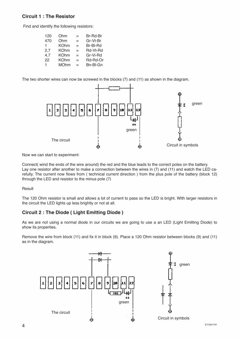
The two shorter wires can now be screwed in the blocks (7) and (11) as shown in the diagram.
The circuit Circuit in symbols
green
Now we can start to experiment:
Connect( wind the ends of the wire around) the red and the blue leads to the correct poles on the battery.Lay one resistor after another to make a connection between the wires in (7) and (11) and watch the LED ca-refully. The current now flows from ( technical current direction ) from the plus pole of the battery (block 12) through the LED and resistor to the minus pole (7)
Result
The 120 Ohm resistor is small and allows a lot of current to pass so the LED is bright. With larger resistors in the circuit the LED lights up less brightly or not at all.
Circuit 2 : The Diode ( Light Emitting Diode )
As we are not using a normal diode in our circuits we are going to use a an LED (Light Emitting Diode) to show its properties.
Remove the wire from block (11) and fix it in block (9). Place a 120 Ohm resistor between blocks (9) and (11) as in the diagram.
The circuit
green
green
Circuit in symbols
green
5E110017#1
Place a Red LED in between the two wires in Block (7) and(9) making a connection and watch what happens. By changing it around you will notice that the green and the red LED will only light together when they are both connected in the same direction . This is because diodes work a little bit like the valve on a cycle which lets air be pumped in but will not let any out,eg.in one direction only.
In the circuit diagram the direction of the current is shown by the arrow head and the line shows the minus connection. The LED also has arrows showing that light is given off. As a normal diode does not give off light on its symbol the arrows are left off.
Take note that:Diodes and light Emitting diodes should never be connected straight to a battery as the current will destroy them. In this experiment this is overcome by using a 120 Ohm resistor to protect them.
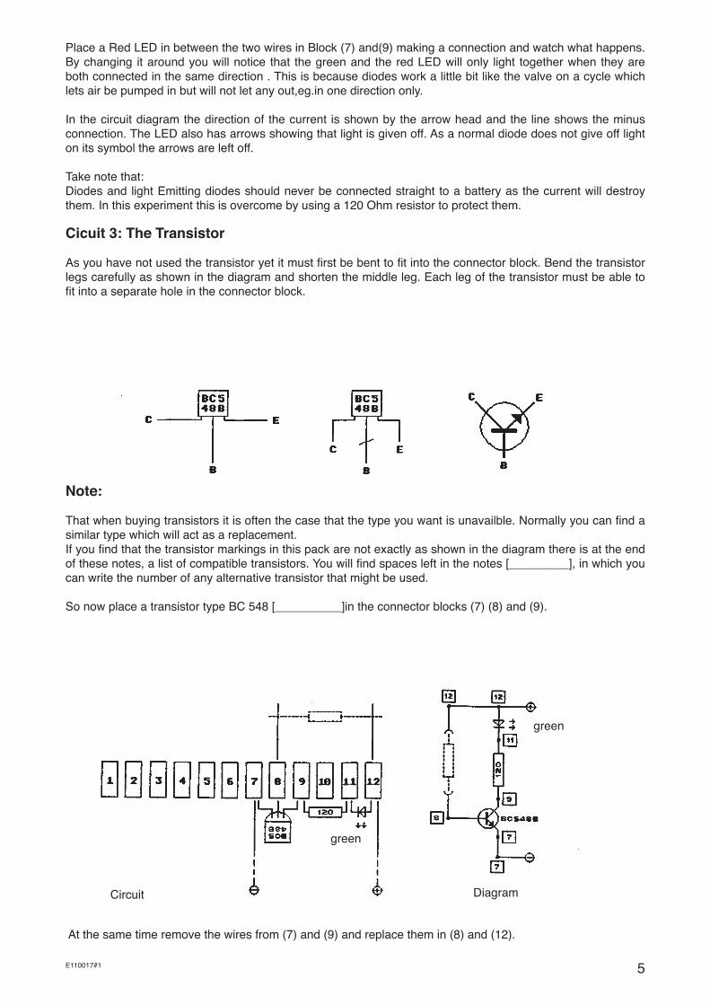
Cicuit 3: The Transistor
As you have not used the transistor yet it must first be bent to fit into the connector block. Bend the transistor legs carefully as shown in the diagram and shorten the middle leg. Each leg of the transistor must be able to fit into a separate hole in the connector block.
Note:
That when buying transistors it is often the case that the type you want is unavailble. Normally you can find a similar type which will act as a replacement. If you find that the transistor markings in this pack are not exactly as shown in the diagram there is at the end of these notes, a list of compatible transistors. You will find spaces left in the notes [_________], in which you can write the number of any alternative transistor that might be used.
So now place a transistor type BC 548 [__________]in the connector blocks (7) (8) and (9).
green
Circuit
green
Diagram
At the same time remove the wires from (7) and (9) and replace them in (8) and (12).

Small input Large Ouput
The Transistor BC 548 B [_________] and the BC 558 B [_________] both have a Collector current which is 200 to 450 times greater than the Base current. Some specialised transistors such as the BC 517 as you will see later, have a Collector current 30 000 larger than the Base current.
Circuit 4: The Capacitor
6 E110017#1
Check your circuit with the diagram. To make it easier to check the circuit the numbers of the connection block are shown on the circuit diagram. The Transistor has 3 connections: the Emitter (E) is connected to block (7) the Collector (C) to (9) and the Base in (8). Connect the battery and watch carefully. Through the LED and the 120 resistor there is a plus (+) current at the Collector (C),and at the Emitter (E) there is a minus(-). The LED does not light and no current flows. This shows that the transistor is 'closed'. Now place a 2,7 K Ohm resistor (Rd-Ve-Rd) between the wires in (8) and (12) and the LED will light up as the transistor is 'switched on.' You now will see that it needs a small current at the base (B) in order to switch it on and allow the current to flow between the Collector (C) and the Emitter(E) Try the same experiment using the 22 KOhm resistor (Rd-Rd-Or).Although the base current is now much smaller it is still enough to 'switch' the transistor on ( The LED lights up) From the first experiment with resi-stors you know that only a small amount of current will pass through and that the LED was vey dim, however the current passing through it is enough to switch the Transistor on. Try again this time using the 1 MOhm re-sistor( 1000 000 Ohm).The LED should still light but only dimly. Alhough the current flowing is only 4 millionth of an Ampere it is enough to switch the Transistor on (only just enough !)You should Note: The Transistor has two uses.
1. It can be used as a SWITCH and the current flowing through the Collector can be stopped.
2. It can be used as an AMPLIFIER in that a small Base current will allow a larger current to flow through the Collector.
Larger Current
Smaller Current
Electrolytic Capacitor Normal Capacitor
Symbol
Component
Look carefully at the Capacitors. The diagram above (left) shows an Electrolytic Capacitor. With this type of Capacitor it very important to identify the plus and minus connections. They must never be connected the wrong way round otherwise the capacitor may explode! and the inner chemicals burst out and cause injury. It is a good policy to identify the plus and minus legs by threading on a small piece of red insulation from a spare piece of wire to identify the positive leg.
On the right hand side is a diagram of a normal Capacitor. With this type of Capacitor the polarity ( which way around it fits ) is not important.

7E110017#1
Alter your last experiment to look like the diagram
The circuit
green
green
Circuit in symbols
The dotted lines show that the connection is not permanent but only needs to be made as necessary.
Connect the battery. The Minus leg of the Capcitor is inserted in block (7) and connected to the Minus wire going to the battery. Now touch the plus leg of the Capacitor on to the connection on block (9) and (10).
By touching the plus of the Capacitor on connection (9) it receives a current via the 120 resistor and the LED and will be charged. The LED will light showing that current is flowing. When the Capacitor is full the current will cease to flow and the LED remain unlit.
Now touch the leg of the Capacitor on to block (10) and it will discharge ( slowly) through the 4,7 KOhm Resi-stor and into the Base(-) of the Transistor turning it on and lighting the LED. This way the Capacitor is being discharged.
The discharge of the Capacitor takes longer as the 4.7K Ohm is very much larger than the 120 resistor.
You should note: A Capacitor can store current ( Be charged up) and give it out again ( Discharged)
In this experiment you have used the largest capacitor in the pack This has a capacity from 470 Micro Farads. Try the same experiment with the 22 Micro Farad Capacitor and you will notice that this time the charge and discharge will be quicker because it has a smaller capacity.
The normal capacitors are really suitable for our experiments. Although they have large number capacities such as 1000 and 47000 they are measured in Pico Farads. This means they can be charged and discharged in seconds. This all happens so quickly that it is not easy to show how they work.
Which type of Capacitor a circuit needs can be seen by the symbols in the diagram.
For those who are especially interested: When the measurement 'Farad' was first used a large unit for 1 Farad was chosen. For example a normal Capacitor with a capacity of 1 Farad would fill a large room. It is no wonder then that in practice very much smaller capacitance is used. The largest ( Electolytic) Capacitor in the pack is 470 uF ( Micro Farad ) The measurement Micro Farad is a millionth part of 1 Farad. The smallest (normal) Capacitor in the pack is 1000Pf. A Pico farad is the millionth part of a Micro Farad and so the billionth part of one Farad. In numbers this is
1 / 1 000 000 000 000
Circuit 5: Optical sensors
Photo resistor = (LDR) Light Dependant Resistor Photo diode = (LDD) Light Dependant Diode Photo transistor = (LDT) Light Dependant Transistor
Optical components are those which react to light. Unfortunately lots of these are expensive. However in the pack there are some examples of the more popular and less expensive types. These components are not
8 E110017#1
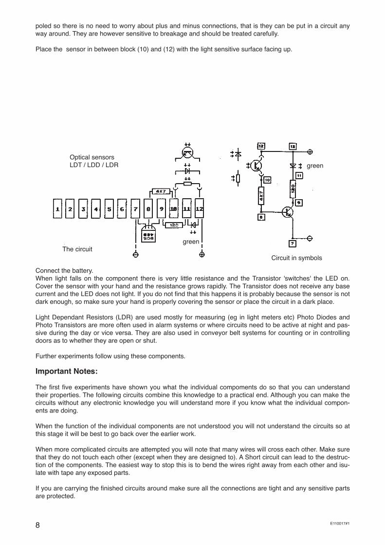
poled so there is no need to worry about plus and minus connections, that is they can be put in a circuit any way around. They are however sensitive to breakage and should be treated carefully.
Place the sensor in between block (10) and (12) with the light sensitive surface facing up.
Optical sensors LDT / LDD / LDR
The circuitCircuit in symbols
Connect the battery.When light falls on the component there is very little resistance and the Transistor 'switches' the LED on. Cover the sensor with your hand and the resistance grows rapidly. The Transistor does not receive any base current and the LED does not light. If you do not find that this happens it is probably because the sensor is not dark enough, so make sure your hand is properly covering the sensor or place the circuit in a dark place.
Light Dependant Resistors (LDR) are used mostly for measuring (eg in light meters etc) Photo Diodes and Photo Transistors are more often used in alarm systems or where circuits need to be active at night and pas-sive during the day or vice versa. They are also used in conveyor belt systems for counting or in controlling doors as to whether they are open or shut.
Further experiments follow using these components.
Important Notes:
The first five experiments have shown you what the individual compoments do so that you can understand their properties. The following circuits combine this knowledge to a practical end. Although you can make the circuits without any electronic knowledge you will understand more if you know what the individual compon-ents are doing.
When the function of the individual components are not understood you will not understand the circuits so at this stage it will be best to go back over the earlier work.
When more complicated circuits are attempted you will note that many wires will cross each other. Make sure that they do not touch each other (except when they are designed to). A Short circuit can lead to the destruc-tion of the components. The easiest way to stop this is to bend the wires right away from each other and isu-late with tape any exposed parts.
If you are carrying the finished circuits around make sure all the connections are tight and any sensitive parts are protected.
green
green
9E110017#1
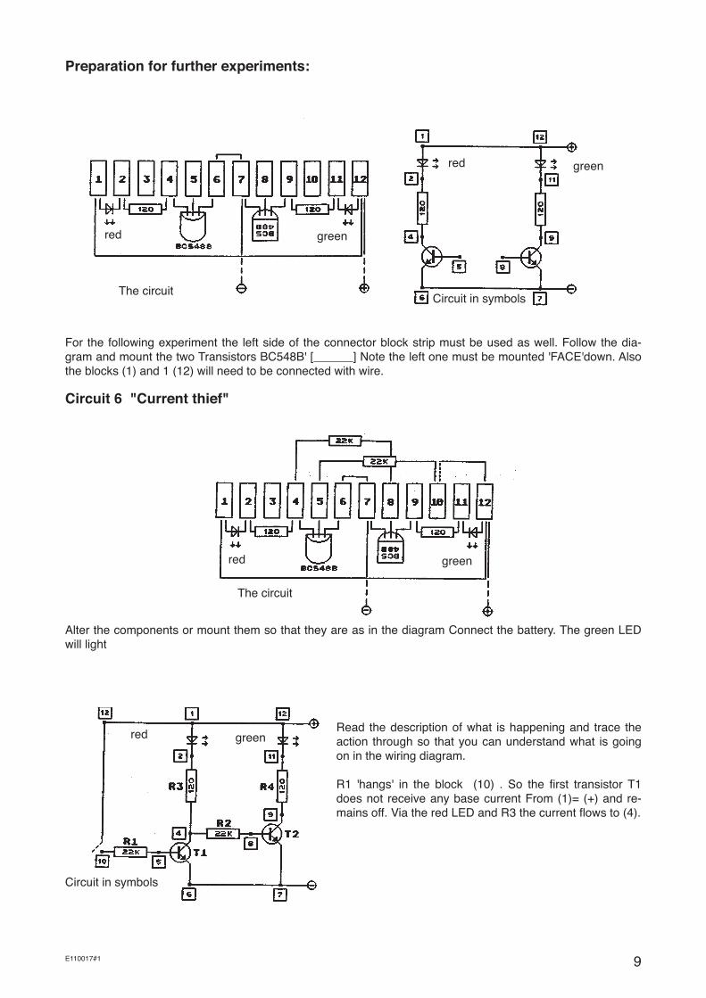
Preparation for further experiments:
red green
The circuit
red green
Circuit in symbols
For the following experiment the left side of the connector block strip must be used as well. Follow the dia-gram and mount the two Transistors BC548B' [______] Note the left one must be mounted 'FACE'down. Also the blocks (1) and 1 (12) will need to be connected with wire.
Circuit 6 "Current thief"
The circuit
red green
Alter the components or mount them so that they are as in the diagram Connect the battery. The green LED will light
Read the description of what is happening and trace the action through so that you can understand what is going on in the wiring diagram.
R1 'hangs' in the block (10) . So the first transistor T1 does not receive any base current From (1)= (+) and re-mains off. Via the red LED and R3 the current flows to (4).
Circuit in symbols
red green
10 E110017#1
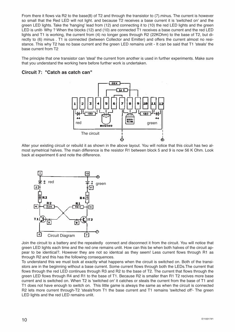
From there it flows via R2 to the base(8) of T2 and through the transistor to (7).minus. The current is however so small that the Red LED will not light. and because T2 receives a base current it is 'switched on' and the green LED lights. Take the 'hanging' lead from (12) and connecting it to (10) the red LED lights and the green LED is unlit- Why ? When the blocks (12) and (10) are connected T1 receives a base current and the red LED lights and T1 is working, the current from (4) no longer goes through R2 (22KOhm) to the base of T2, but di-rectly to (6) minus . T1 is connected (between Collector and Emitter) and offers the current almost no resi-stance. This why T2 has no base current and the green LED remains unlit - It can be said that T1 'steals' the base current from T2
The principle that one transistor can 'steal' the current from another is used in further experiments. Make sure that you understand the working here before further work is undertaken.
Circuit 7: "Catch as catch can"
The circuit
Alter your existing circuit or rebuild it as shown in the above layout. You will notice that this cicuit has two al-most symetrical halves. The main difference is the resistor R1 between block 5 and 9 is now 56 K Ohm. Look back at experiment 6 and note the difference.
Circuit Diagram
Join the circuit to a battery and the repeatedly connect and disconnect it from the circuit. You will notice that green LED lights each time and the red one remains unlit. How can this be when both halves of the circuit ap-pear to be identical?. However they are not so identcal as they seem! Less current flows through R1 as through R2 and this has the following consequences. To understand this we must look at exactly what happens when the circuit is switched on. Both of the transi-stors are in the beginning without a base current. Some current flows through both the LEDs.The current that flows through the red LED continues through R3 and R2 to the base of T2. The current that flows through the green LED flows through R4 and R1 to the base of T1. Because R2 is smaller than R1 T2 recives more base current and is switched on. When T2 is 'switched on' it catches or steals the current from the base of T1 and T1 does not have enough to switch on. This little game is always the same as when the circuit is connected R2 lets more current through-T2 'steals'from T1 the base current and T1 remains 'switched off'- The green LED lights and the red LED remains unlit.
red green
red green

11E110017#1
Circuit layout Circuit Diagram
The layout for this circuit is the same as the previous one. However you will need some extra wire for connec-tions. So that the red LED will light we must shut off T2. Connect between block (8) and (9) with a piece of wire and the red LED will light and the green LED will remain off. With the wire connection the current for the base of T2 has been 'stolen' while we have connected block (7) to minus.
- When T2 has no base current it is 'switched off' - When T2 is closed, T1 recieves a base current via R1 and is 'switched on' - When T1 is 'on', it 'steals the base current from T2.
So the red LED is lit and the green one remains off.If you want the green LED to light up you have to make a connection with wire between block (5) and (7). You will notice that it cannot swith from one LED to another on its own and a separate connection must be made each time to change the states. This is called a Bistabile circuit. Because this circuit will remain in a given state until switched it is often used as a memory in calcula-tors and computers. Now try putting longer length of wire in blocks (5) and (7) and bending the ends to con-tacts so that when a door shuts the wire ends will touch. When you switch the circuit on the Green LED will light and by making a contact wire between blocks (7) and (8) the red LED will light. Now you can leave the circuit set up and go away.If someone else uses the 'secured'door whilst you are away the green LED will come on and the red LED will go off. Even switching the circuit on and off will not change the state. Only so-meone who knows how the circuit works will be able to reset it.
Circuit 8 " The Flip Flop "
red green
red green
12 E110017#1
Circuit in symbols
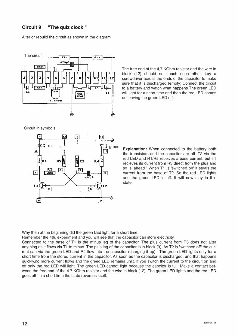
Explanation: When connected to the battery both the transistors and the capacitor are off. T2 via the red LED and R1/R5 receives a base current, but T1 recieves its current from R3 direct from the plus and so is' ahead ' When T1 is 'switched on' it steals the current from the base of T2. So the red LED lights and the green LED is off. It will now stay in this state.
Why then at the beginning did the green LEd light for a short time.Remember the 4th. experiment and you will see that the capacitor can store electricity. Connected to the base of T1 is the minus leg of the capacitor. The plus current from R3 does not alter anything as it flows via T1 to minus. The plus leg of the capacitor is in block (9). As T2 is 'switched off',the cur-rent can via the green LED and R4 flow into the capacitor (charging it up). The green LED lights only for a short time from the stored current in the capacitor. As soon as the capacitor is discharged, and that happens quickly,no more current flows and the greed LED remains unlit. If you switch the current to the circuit on and off only the red LED will light. The green LED cannot light because the capcitor is full. Make a contact bet-ween the free end of the 4.7 KOhm resistor and the wire in block (12). The green LED lights and the red LED goes off- in a short time the state reverses itself.
The free end of the 4,7 KOhm resistor and the wire in block (12) should not touch each other. Lay a screwdriver across the ends of the capacitor to make sure that it is discharged (empty).Connect the circuit to a battery and watch what happens The green LED will light for a short time and then the red LED comes on leaving the green LED off.
Circuit 9 "The quiz clock "
Alter or rebuild the circuit as shown in the diagram
The circuit
rot green
13E110017#1
ExplanationWhen R2 is connected to the plus enough current flows via the 4,7 KOhm to the base of the transistor T2 and switches it on. T1 switches on split seconds later but it cannot 'steal' the base current because R5 is in bet-ween and with a resistance 22 KOhm is a large obstacle. Also T2 is switched on.Whilst T2 is on ,the plus leg of the capacitor via T2 with is connected with minus , and thus discharged. When discharging there is not sim-ply current flowing out of the plus leg but at the same time there must be the same amount flowing in to the minus leg. This can only come through R3. So when discharging the capacitor takes away the base current of T1 and switches it off. So long as T1 is off, T2 recieves a base current via R5 and the green LED lights again, also when the contact between R2 and block (12) is broken. Because via the 22 KOhm resistor R3 only a small amount of current passes T2 is switched on for a long time. It follows that at the sane time the capacitor can only be loaded relatively slowly
When the capcitor is discharged T1 receives its base current again and 'steals' the base current from T2. T2 switches off, and the capacitor is recharged (loaded) again. So the green LED lights for a short while even when the red is still on. Now a stable state has been achieved. This circuit has only one stable state and is therfore called a Mono stable circuit. (Mono means one)
Note
You will surely not have understood this explanation in the first go as what is happening is a little complicated and tricky! However keep going and try to see if you can see and understand what is happening by looking at the circuit diagram. If you can manage to work it out the other experiments will come easy.
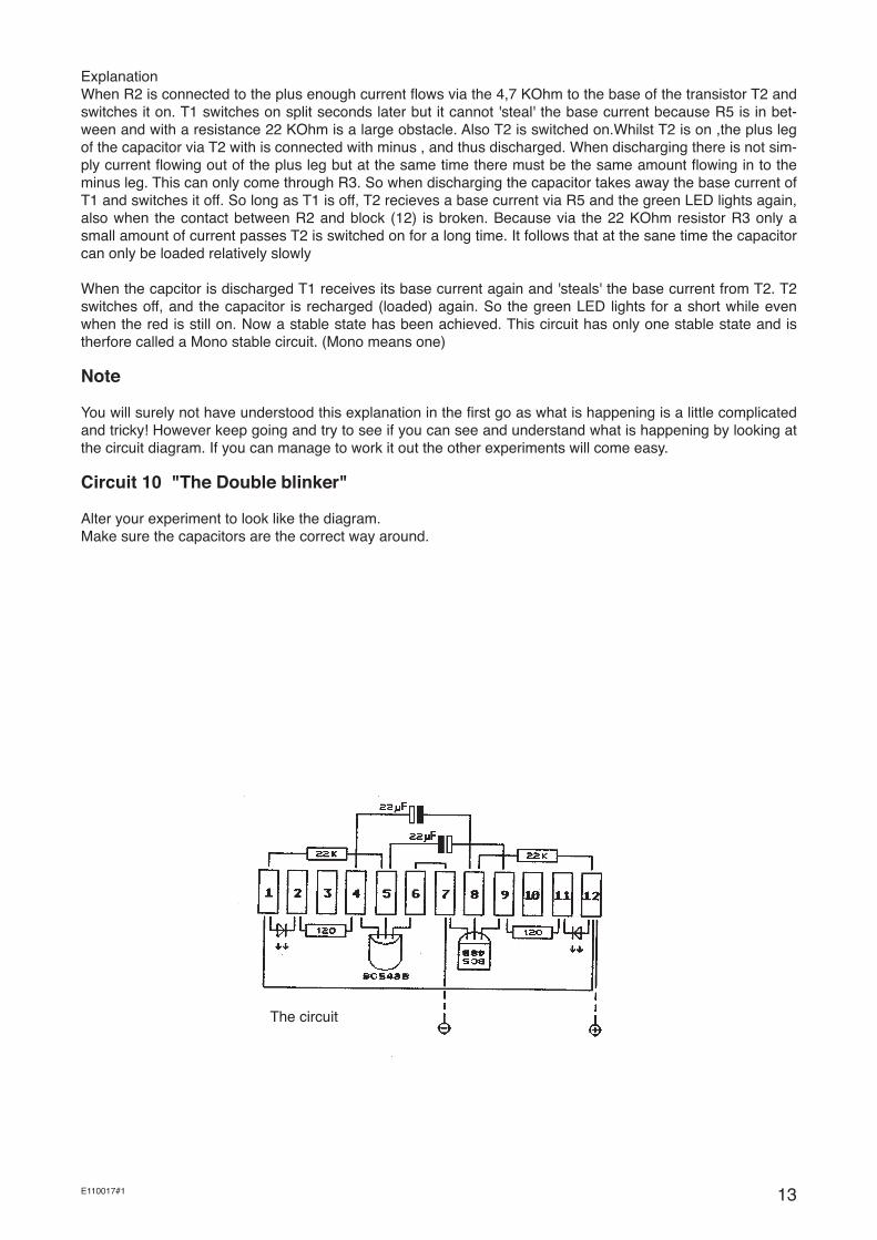
Circuit 10 "The Double blinker"
Alter your experiment to look like the diagram. Make sure the capacitors are the correct way around.
The circuit
14 E110017#1
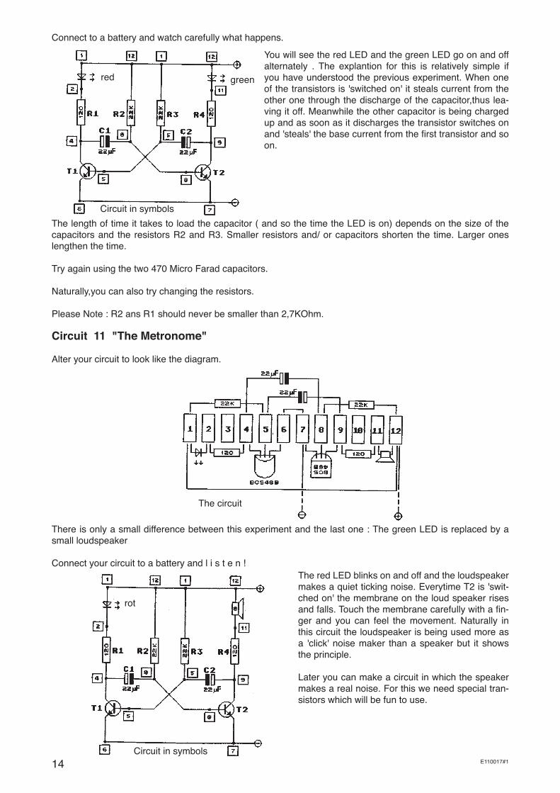
Connect to a battery and watch carefully what happens.
You will see the red LED and the green LED go on and off alternately . The explantion for this is relatively simple if you have understood the previous experiment. When one of the transistors is 'switched on' it steals current from the other one through the discharge of the capacitor,thus lea-ving it off. Meanwhile the other capacitor is being charged up and as soon as it discharges the transistor switches on and 'steals' the base current from the first transistor and so on.
The length of time it takes to load the capacitor ( and so the time the LED is on) depends on the size of the capacitors and the resistors R2 and R3. Smaller resistors and/ or capacitors shorten the time. Larger ones lengthen the time.
Try again using the two 470 Micro Farad capacitors.
Naturally,you can also try changing the resistors.
Please Note : R2 ans R1 should never be smaller than 2,7KOhm.
Circuit 11 "The Metronome"
Alter your circuit to look like the diagram.
The circuit
There is only a small difference between this experiment and the last one : The green LED is replaced by a small loudspeaker
Connect your circuit to a battery and l i s t e n !
Circuit in symbols
The red LED blinks on and off and the loudspeaker makes a quiet ticking noise. Everytime T2 is 'swit-ched on' the membrane on the loud speaker rises and falls. Touch the membrane carefully with a fin-ger and you can feel the movement. Naturally in this circuit the loudspeaker is being used more as a 'click' noise maker than a speaker but it shows the principle.
Later you can make a circuit in which the speaker makes a real noise. For this we need special tran-sistors which will be fun to use.
red green
Circuit in symbols
rot

15
Circuit 12 "The Darlington Switch"
For this experiment we two normal transistors type BC 548 B [___________]. If you have built experiment 11 you do not need to take everything apart, but use instead the second connector block and the necessary components.
The circuit
Connect your circuit to a battery and watch what hap-pens. Lay a 22KOhm resistor across the wires com-ming out block(1) and (8).You will notice that the LED will light up brightly because T2 recieves enough base current. (T1 takes part in this circuit ) Change the resi-stor for 1MOhm and the LED will only now be faintly lit.This is because the base of T2 only just recives enough current to switch it on. Now place the same resistor across the wires from block (1) and (5) and this time the LED will be bright again showing that T2 has a good base current Explanation: As you have seen before it only takes a little current through the 1-M Ohm resistor to make it 'switch on'. This is exactly what happened with T1. The much greater collector current from T1 makes up the base current of T2 and this switches it fully on. Because this kind of circuit is often used a special type
of transistor has been developed, such as the BC 517, which although it looks the same as the others outside the inside contains two transistors in a Darlington layout.
Circuit 13 The "Elektroscope"
Circuit in symbols
The circuit
red
red
Sonde
red
16 E110017#1
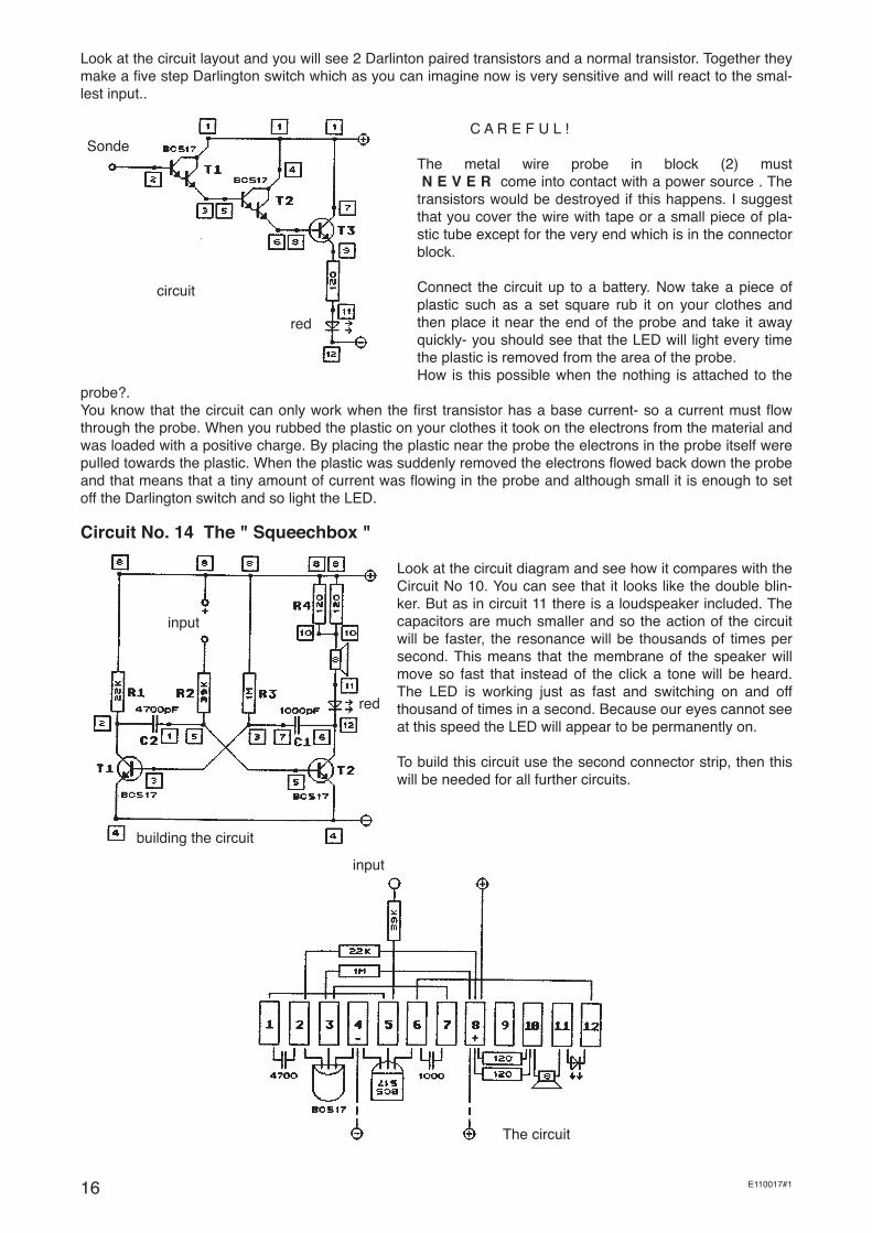
Look at the circuit layout and you will see 2 Darlinton paired transistors and a normal transistor. Together they make a five step Darlington switch which as you can imagine now is very sensitive and will react to the smal-lest input..
C A R E F U L !
The metal wire probe in block (2) must N E V E R come into contact with a power source . The transistors would be destroyed if this happens. I suggest that you cover the wire with tape or a small piece of pla-stic tube except for the very end which is in the connector block.
Connect the circuit up to a battery. Now take a piece of plastic such as a set square rub it on your clothes and then place it near the end of the probe and take it away quickly- you should see that the LED will light every time the plastic is removed from the area of the probe.How is this possible when the nothing is attached to the
probe?.You know that the circuit can only work when the first transistor has a base current- so a current must flow through the probe. When you rubbed the plastic on your clothes it took on the electrons from the material and was loaded with a positive charge. By placing the plastic near the probe the electrons in the probe itself were pulled towards the plastic. When the plastic was suddenly removed the electrons flowed back down the probe and that means that a tiny amount of current was flowing in the probe and although small it is enough to set off the Darlington switch and so light the LED.
Circuit No. 14 The " Squeechbox "
Look at the circuit diagram and see how it compares with the Circuit No 10. You can see that it looks like the double blin-ker. But as in circuit 11 there is a loudspeaker included. The capacitors are much smaller and so the action of the circuit will be faster, the resonance will be thousands of times per second. This means that the membrane of the speaker will move so fast that instead of the click a tone will be heard. The LED is working just as fast and switching on and off thousand of times in a second. Because our eyes cannot see at this speed the LED will appear to be permanently on.
To build this circuit use the second connector strip, then this will be needed for all further circuits.
circuit
Sonde
red
input
building the circuit
red
input
The circuit

17E110017#1
So that the 'Squeechbox'is activated the 'input' wire will needed to be connected to Plus. You can do this with a length of wire or place your hand such that one finger touches the input and another the plus.
Note: both of the 120-Ohm- resistors are placed in parallel this circuit and function as a single 60- Ohm- resi-stance.
Circuit 15. The "Super - Squeech box"
We did not spend much time on the last circuit. This is because it is relatively simple and easy to understand. It is however not very loud and as we made this circuit to work in a control situation we will need to make it louder-thus this circuit is called a 'Super-Squeech Box'
The circuit
The construction of this circuit is a little more complicated ,as three transistors and other components must be added.Make sure that you lay the components out carefully and nothing is touching that will cause a short cir-cuit.
As you can see in the circuit diagram there is now a transistor type 'BC 558/557 B' [__________] included in the circuit. This is the opposite to the normal NPN transistors and is connected in a different way in the circuit. The Emitter does not go to minus but to plus, apart from this it functions as normal.
What does this transistor do in the circuit ? very easy : it feeds the loudspeaker with as much current as pos-sible to make it louder.This is why apart from the transistor only the two LEDs and the loudspeaker are bet-ween the Plus and the Minus. As one LED (in this case) takes too much current we will use the same 'trick' as we did earlier with the two resistors eg. place them in parallel so that there is only half as much resistance as with one. Also the LEDs protect the circuit without too much resistance while they are not permanently on and can 'breathe 'so to speak. In the normal sqeechbox you can see that apart from the LED and the Loudspeaker a protective resistance of 60 Ohms is by the collector of T2. This is because if the resistance is too small the circuit will not 'tip' (function) properly.For the same reason the Super Sqeechbox has a 470 Ohm resistance. This used as a Collector resistance and just large enough to 'tip' the circuit. This in turn controls the Base of T3.
input
input
red
BC557
BC 557

18 E110017#1
What makes the Super Sqeechbox so super ?
1. The circuit does not use much current when mot in use ( when there is no noise) and therefore pro longs the life of the battery.
2. The circuit is robust as when the input is connected to plus nothing will be damaged.
3. The switching is super sensitive as it only needs 10 millionth of an Ampere at the input to set it off.
4. The circuit can easily be incorporated into other circuits and used with optical and acustic inputs.
How can you use the 'Super Sqeechbox'
Ask all your friends to stand in a circle, the first person holds the plus connection and the last the input. As soon as you all hold hands the Super sqeechbox sounds. As soon as the circle is broken the loudspeaker will stop. Try it with as many as 60 pupils in a circle It should even work with twice that number- Have a go !.
Circuit 16 The "Light switch"
This circuit is not really designed to be used alone but in conjunction with the Super squeechbox.
The circuit
Build this circuit extra to the Squeechbox or Super Queechbox using the other connector strip. If you connect the plus and the minus from both strips you will only need one battery. The output of the light circuit can be connected to the input of the 'Box'
From circuit 5 you know that the sensor can react to a side light. As we do not want this to happen use a piece of plastic tubing from an old felt tip pen or biro to mount the sensor in. You can hold it in place with a small piece of cork or rubber so that it does not move about. If it is carried out properly the light should only fall on the flat part of the sensor.
When you want to try the system shine a torch on to the sensor or hold it to the window.If you pass your finger in front of the sensor the alarm should stop.
outputred
19E110017#1
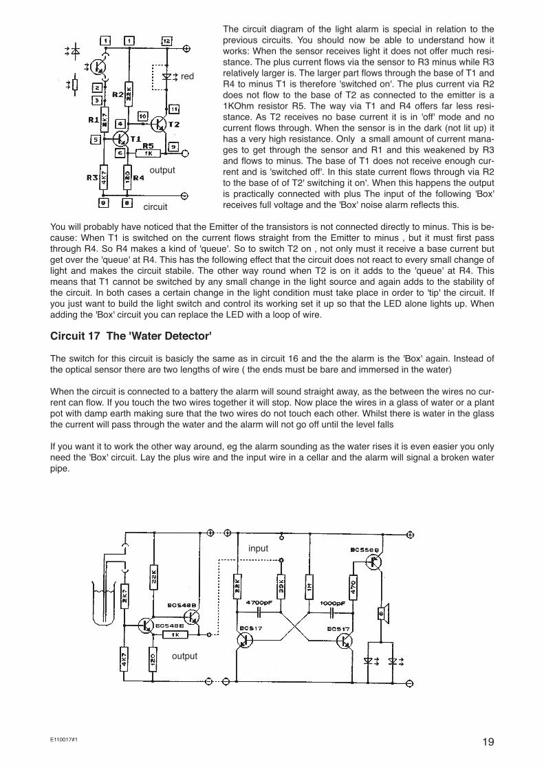
The circuit diagram of the light alarm is special in relation to the previous circuits. You should now be able to understand how it works: When the sensor receives light it does not offer much resi-stance. The plus current flows via the sensor to R3 minus while R3 relatively larger is. The larger part flows through the base of T1 and R4 to minus T1 is therefore 'switched on'. The plus current via R2 does not flow to the base of T2 as connected to the emitter is a 1KOhm resistor R5. The way via T1 and R4 offers far less resi-stance. As T2 receives no base current it is in 'off' mode and no current flows through. When the sensor is in the dark (not lit up) it has a very high resistance. Only a small amount of current mana-ges to get through the sensor and R1 and this weakened by R3 and flows to minus. The base of T1 does not receive enough cur-rent and is 'switched off'. In this state current flows through via R2 to the base of of T2' switching it on'. When this happens the output is practically connected with plus The input of the following 'Box' receives full voltage and the 'Box' noise alarm reflects this.
You will probably have noticed that the Emitter of the transistors is not connected directly to minus. This is be-cause: When T1 is switched on the current flows straight from the Emitter to minus , but it must first pass through R4. So R4 makes a kind of 'queue'. So to switch T2 on , not only must it receive a base current but get over the 'queue' at R4. This has the following effect that the circuit does not react to every small change of light and makes the circuit stabile. The other way round when T2 is on it adds to the 'queue' at R4. This means that T1 cannot be switched by any small change in the light source and again adds to the stability of the circuit. In both cases a certain change in the light condition must take place in order to 'tip' the circuit. If you just want to build the light switch and control its working set it up so that the LED alone lights up. When adding the 'Box' circuit you can replace the LED with a loop of wire.
Circuit 17 The 'Water Detector'
The switch for this circuit is basicly the same as in circuit 16 and the the alarm is the 'Box' again. Instead of the optical sensor there are two lengths of wire ( the ends must be bare and immersed in the water)
When the circuit is connected to a battery the alarm will sound straight away, as the between the wires no cur-rent can flow. If you touch the two wires together it will stop. Now place the wires in a glass of water or a plant pot with damp earth making sure that the two wires do not touch each other. Whilst there is water in the glass the current will pass through the water and the alarm will not go off until the level falls
If you want it to work the other way around, eg the alarm sounding as the water rises it is even easier you only need the 'Box' circuit. Lay the plus wire and the input wire in a cellar and the alarm will signal a broken water pipe.
red
output
circuit
input
output

20 E110017#1
The circuit diagram shows you how you can join the 'light alarm' or other sensors to a 'Super Squeech' Noise system'
Different uses of this sort of circuit are found in such things as automatic doors,counting goods on a conveyor belt, security in corridors and in the use of machines where being near them in action is dangerous. Street lights can also be made to switch on and off automatically.
Further Uses:
The same trigger switches and as in circuit 16 and 17 can be used for other things when the optical sensor is replaced. If a Thermal resistance is used a temperature sensing circuit can be made which can be used as a fire detector or as frost detector. Unfortnately these sensors are expensive and are not included in the pack. They also need to be more accurately set up than our experiments.
The last word:
You have now come to the end of the experiments. I hope you have enjoyed working with the circuits and have learnt something about electronics. If you have, then there are many other ideas for you to continue your experiments with.
Advice:
When you want to join other circuits to the 'Box' use the circuit diagrams as a guide. In the other circuits there is no output shown- you can use the collector connection of a transistor as an output- it cannot do any dama-ge.
Try joining the double blinker and the 'Box' so that you have lights and noise in unison.
I am sure you can think of other combinations
When you want to use other components try finding an old radio, there should be some components you can use. It may be that some of these have been damaged, so use them in a circuit you know has worked. eg change a single capacitor or resistor. Keep an eye on thecircuit diagrams and notes to make sure you do not destroy your work.
21E110017#1
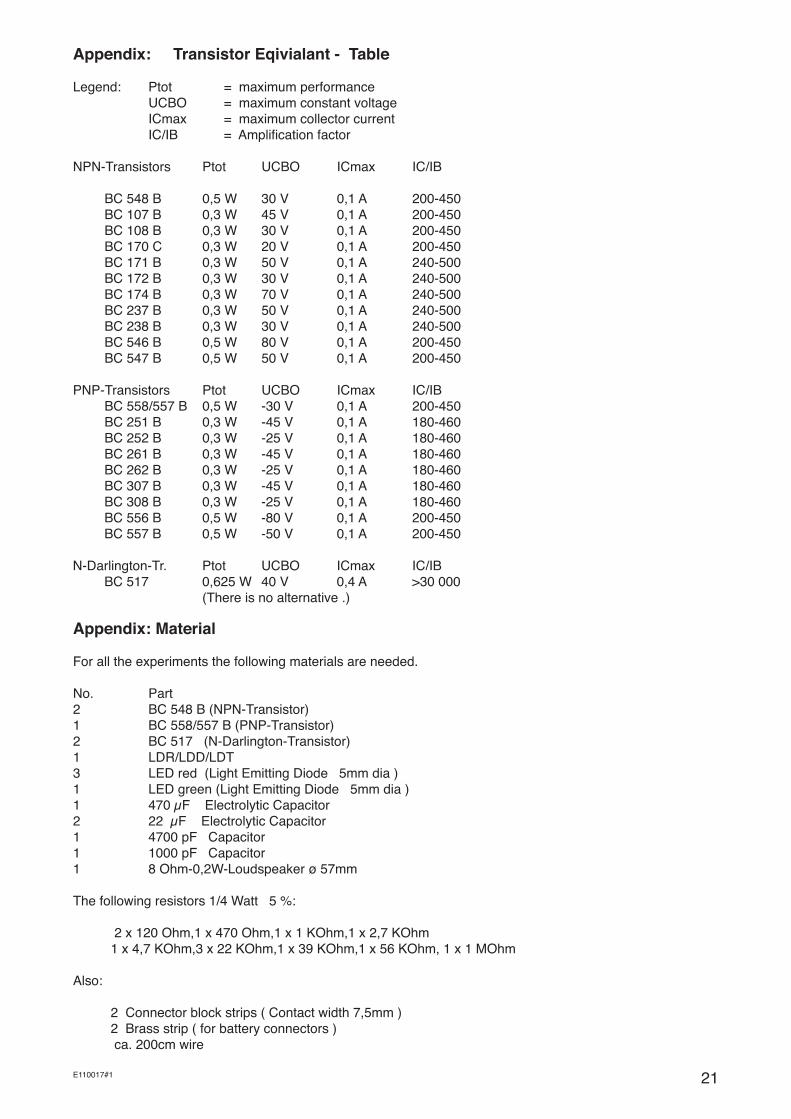
Appendix: Transistor Eqivialant - Table
Legend: Ptot = maximum performance UCBO = maximum constant voltage ICmax = maximum collector current IC/IB = Amplification factor
NPN-Transistors Ptot UCBO ICmax IC/IB BC 548 B 0,5 W 30 V 0,1 A 200-450 BC 107 B 0,3 W 45 V 0,1 A 200-450 BC 108 B 0,3 W 30 V 0,1 A 200-450 BC 170 C 0,3 W 20 V 0,1 A 200-450 BC 171 B 0,3 W 50 V 0,1 A 240-500 BC 172 B 0,3 W 30 V 0,1 A 240-500 BC 174 B 0,3 W 70 V 0,1 A 240-500 BC 237 B 0,3 W 50 V 0,1 A 240-500 BC 238 B 0,3 W 30 V 0,1 A 240-500 BC 546 B 0,5 W 80 V 0,1 A 200-450 BC 547 B 0,5 W 50 V 0,1 A 200-450
PNP-Transistors Ptot UCBO ICmax IC/IB BC 558/557 B 0,5 W -30 V 0,1 A 200-450 BC 251 B 0,3 W -45 V 0,1 A 180-460 BC 252 B 0,3 W -25 V 0,1 A 180-460 BC 261 B 0,3 W -45 V 0,1 A 180-460 BC 262 B 0,3 W -25 V 0,1 A 180-460 BC 307 B 0,3 W -45 V 0,1 A 180-460 BC 308 B 0,3 W -25 V 0,1 A 180-460 BC 556 B 0,5 W -80 V 0,1 A 200-450 BC 557 B 0,5 W -50 V 0,1 A 200-450
N-Darlington-Tr. Ptot UCBO ICmax IC/IB BC 517 0,625 W 40 V 0,4 A >30 000 (There is no alternative .)
Appendix: Material
For all the experiments the following materials are needed.
No. Part2 BC 548 B (NPN-Transistor)1 BC 558/557 B (PNP-Transistor)2 BC 517 (N-Darlington-Transistor)1 LDR/LDD/LDT3 LED red (Light Emitting Diode 5mm dia )1 LED green (Light Emitting Diode 5mm dia )1 470 µF Electrolytic Capacitor2 22 µF Electrolytic Capacitor1 4700 pF Capacitor1 1000 pF Capacitor1 8 Ohm-0,2W-Loudspeaker ø 57mm
The following resistors 1/4 Watt 5 %:
2 x 120 Ohm,1 x 470 Ohm,1 x 1 KOhm,1 x 2,7 KOhm 1 x 4,7 KOhm,3 x 22 KOhm,1 x 39 KOhm,1 x 56 KOhm, 1 x 1 MOhm
Also:
2 Connector block strips ( Contact width 7,5mm ) 2 Brass strip ( for battery connectors ) ca. 200cm wire
22 E110017#1
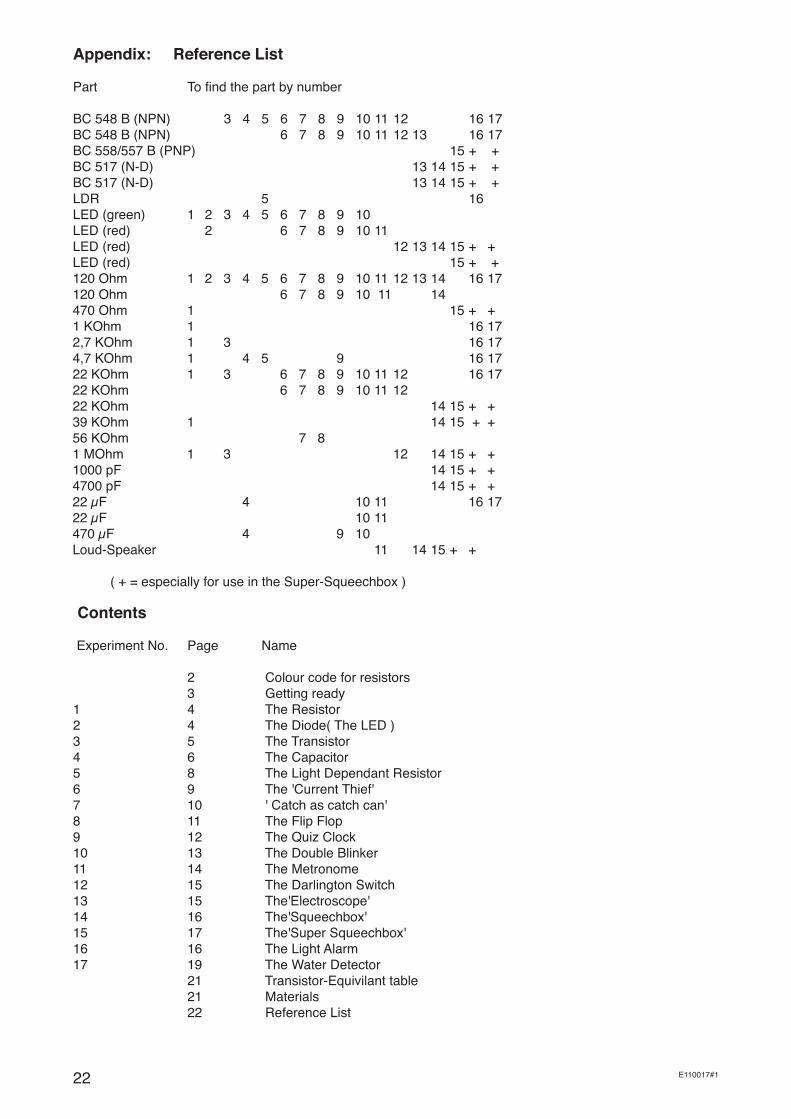
Appendix: Reference List
Part To find the part by number BC 548 B (NPN) 3 4 5 6 7 8 9 10 11 12 16 17BC 548 B (NPN) 6 7 8 9 10 11 12 13 16 17BC 558/557 B (PNP) 15 + +BC 517 (N-D) 13 14 15 + +BC 517 (N-D) 13 14 15 + +LDR 5 16LED (green) 1 2 3 4 5 6 7 8 9 10LED (red) 2 6 7 8 9 10 11LED (red) 12 13 14 15 + +LED (red) 15 + +120 Ohm 1 2 3 4 5 6 7 8 9 10 11 12 13 14 16 17120 Ohm 6 7 8 9 10 11 14470 Ohm 1 15 + +1 KOhm 1 16 172,7 KOhm 1 3 16 174,7 KOhm 1 4 5 9 16 1722 KOhm 1 3 6 7 8 9 10 11 12 16 1722 KOhm 6 7 8 9 10 11 1222 KOhm 14 15 + +39 KOhm 1 14 15 + +56 KOhm 7 81 MOhm 1 3 12 14 15 + +1000 pF 14 15 + +4700 pF 14 15 + +22 µF 4 10 11 16 1722 µF 10 11470 µF 4 9 10Loud-Speaker 11 14 15 + +
( + = especially for use in the Super-Squeechbox )
Contents
Experiment No. Page Name
2 Colour code for resistors 3 Getting ready1 4 The Resistor2 4 The Diode( The LED )3 5 The Transistor4 6 The Capacitor5 8 The Light Dependant Resistor6 9 The 'Current Thief'7 10 ' Catch as catch can'8 11 The Flip Flop9 12 The Quiz Clock10 13 The Double Blinker11 14 The Metronome12 15 The Darlington Switch13 15 The'Electroscope'14 16 The'Squeechbox'15 17 The'Super Squeechbox'16 16 The Light Alarm17 19 The Water Detector 21 Transistor-Equivilant table 21 Materials 22 Reference List


![Cytokine Production the and Stages · CYTOKINESINTHEMURINEUTERUS 37 120 110-100 90-80-70-60-40-20 l 10 0 120 110 I00 9O 8O 70 6O 5O 4O 30 2O 10 0 A P 0 D2 03 A P 0 D2 D3 120] 110-tO0](https://static.fdocuments.us/doc/165x107/5e35b5bf01660a666e727574/cytokine-production-the-and-stages-cytokinesinthemurineuterus-37-120-110-100-90-80-70-60-40-20.jpg)