
110 and 112 Lawn and Garden Tractors Serial No. (100,001 ...nance information for John Deere 110 and...
55
110 and 112 Lawn and Garden Tractors Serial No. (100,001 - 250,000) SERVICE MANUAL 110 and 112 Lawn and Garden Tractors Serial No. (100,001 - 250,000) SM2088 (01NOV69) English John Deere Lawn & Grounds Care Division SM2088 (01NOV69) LITHO IN U.S.A. ENGLISH D C Y SM2088 01NOV69
Transcript of 110 and 112 Lawn and Garden Tractors Serial No. (100,001 ...nance information for John Deere 110 and...
110 and 112Lawn and
Garden TractorsSerial No.
(100,001 - 250,000)
SERVICE MANUAL110 and 112 Lawn and Garden Tractors
Serial No. (100,001 - 250,000)
SM2088 (01NOV69) English
John DeereLawn & Grounds Care Division
SM2088 (01NOV69)
LITHO IN U.S.A.ENGLISH
DC
YS
M2
08
8
0
1N
OV
69

'"'-----"
SECTION 10 - GENERAL Group 5 - Tractor Identification Group 10 - Specifications Group 15 - Tune-Up and Adjustment Group 20 - Fuel and Lubricants
SECTION 20 - ENGINE Kohler Engines Group 5 - General Information Group 10 - Cylinder Head, Valves and
Breather Group 15 - Piston, Crankshaft, Main .Bear-
ings and Flywheel Group 20 - Camshaft, Tappets and Gover-
nor
Tecumseh Engine Group 25 - General Information Group 30 - Cylinder Heqd, Valves and
Breather Group 35 - Piston, Crankshaft, Main Bear-
ings and Flywheel Group 40 - Camshaft, Tappets and Governor
SECTION 30 - FUEL SYSTEM Group 5 - General Information Group 10 - Carburetor Group 15 - Air Cleaner Group 20 - Sediment Bowl, Fuel Strainer
and Gas Tank Group 25 - Fuel Pump (112 Kohler Only)
Litho in U.S.A.
1
Service Manual 110 AND 112 LAWN AND
GARDEN TRACTORS (Serial No. 100,001- )
CONTENTS
SECTION 40 - ELECTRICAL SYSTEM Group 5 - General Information Group 10 - Cranking System Group 15 - Ignition System (Magneto) Group 20 - Ignition System (Battery) Group 25 - Ignition System (Solid State) Group 30 - Charging System
SECTION 50 - POWER TRAIN Group 5 - General Information Group 10 - Clutch, Brake and Variable
Speed Drive Group 15 - 4-Speed Transaxle
SECTION 60 - HYDRAULIC SYSTEM Group 5 - General Information Group 10 - Control Valve Group 15 - Pump Group 20 - Cylinder
SECTION 70 - MISCELLANEOUS Group 5 - Steering Linkage Group 10- Front Wheels and Axles Group 15 - Lift Linkage
Copyright 1969 DEERE & COMPANY
MOline, Illinois AI! rights reserved
Tractors, 110 and 112 (Serial No. 100,001- ) 2 SM-2088- (Nov-69)
INTRODUCTION
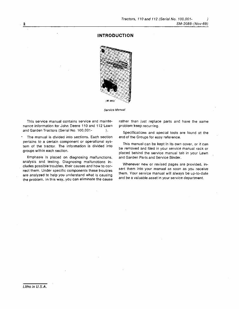
Service Manual
This service manual contains service and mainte-nance information for John Deere 110 and 112 Lawn and Garden Tractors (Serial No.1 00,001- ).
The manual is divided into sections. Each section pertains to a certain component or operational sys-tem of the tractor. The information is divided into groups within each section.
Emphasis is placed on diagnosing malfunctions, analysis and testing. Diagnosing malfunctions in-cludes possible troubles, their causes and how to cor-rect them. Under specific components these troubles are analyzed to help you understand what is causing the problem. In this way, you can eliminate the cause
Litho in U.S.A.
rather than just replace parts and have the same problem keep recurring.
Specifications and special tools are found at the end of the Groups for easy reference.
This manual can be kept in its own cover, or it can be removed and filed in your service manual rack or placed behind the service manual tab in your Lawn and Garden Parts and Service Binder.
Whenever new or revised pages are provided, in-sert them into your manual as soon as you receive them. Your service manual will a/ways be up-to-date and be a valuable asset in your service department.
Section 10 GENERAL
Group 5 TRACTOR IDENTIFICATION
TABLE OF CONTENTS
GROUP 5 - TRACTOR IDENTIFICATION Page
Serial Numbers .......................... 5-2 Vintage Information ...................... 5-2 Serial Number Plates ..................... 5-3 Identification Codes ...................... 5-3
GROUP 10 - SPECIFICATIONS Engine Specifications .................... 10-1 Electrical System ....................... 10-1 Capacities ............................. 10-1 Fuel and Lubricant. . . . . . . . . . . . . . . . . . . .. .10-2 Transmission and Axle ................... 10-2 Brakes, Clutch and Steering ............... 10-2 Curb Weights .......................... 10-2 Tire Specifications and Tractor Dimensions .. 10-3 Bolt Torque Chart ....................... 10-4 Set Screw Seating Torque Chart ........... 10-4
Litho in U.S.A.
GROUP 15 - TUNE-UP AND ADJUSTMENT Page
Preliminary Engine Testing. . . . . . . . . . . . . .. 15-1 Minor Tune-Up Guide . . . . . . . . . . . . . . . . . .. 15-1 Major Tune-Up Guide . . . . . . . . . . . . . . . . . .. 15-2
GROUP 20 - FUEL AND LUBRICANTS Fuel ................................. 20-1 Lubricants . . . . . . . . . . . . . . . . . . . . . . . . . . .. 20-1 Capacities . . . . . . . . . . . . . . . . . . . . . . . . . . .. 20-1 Type of Lubricant ...................... 20-2 Service Intervals . . . . . . . . . . . . . . . . . . . . . . . 20-2 Changing Crankcase Oil ................ 20-3 Changing Transaxle Oil ................ 20-3 Grease Fitting Locations ................. 20-4 Repack PTO Clutch Bearing .............. 20-4
10 General Tractors, 110and 112 (Serial No. 100,001- ) 5-2 Tractor Identification SM-2088- (Nov-70)
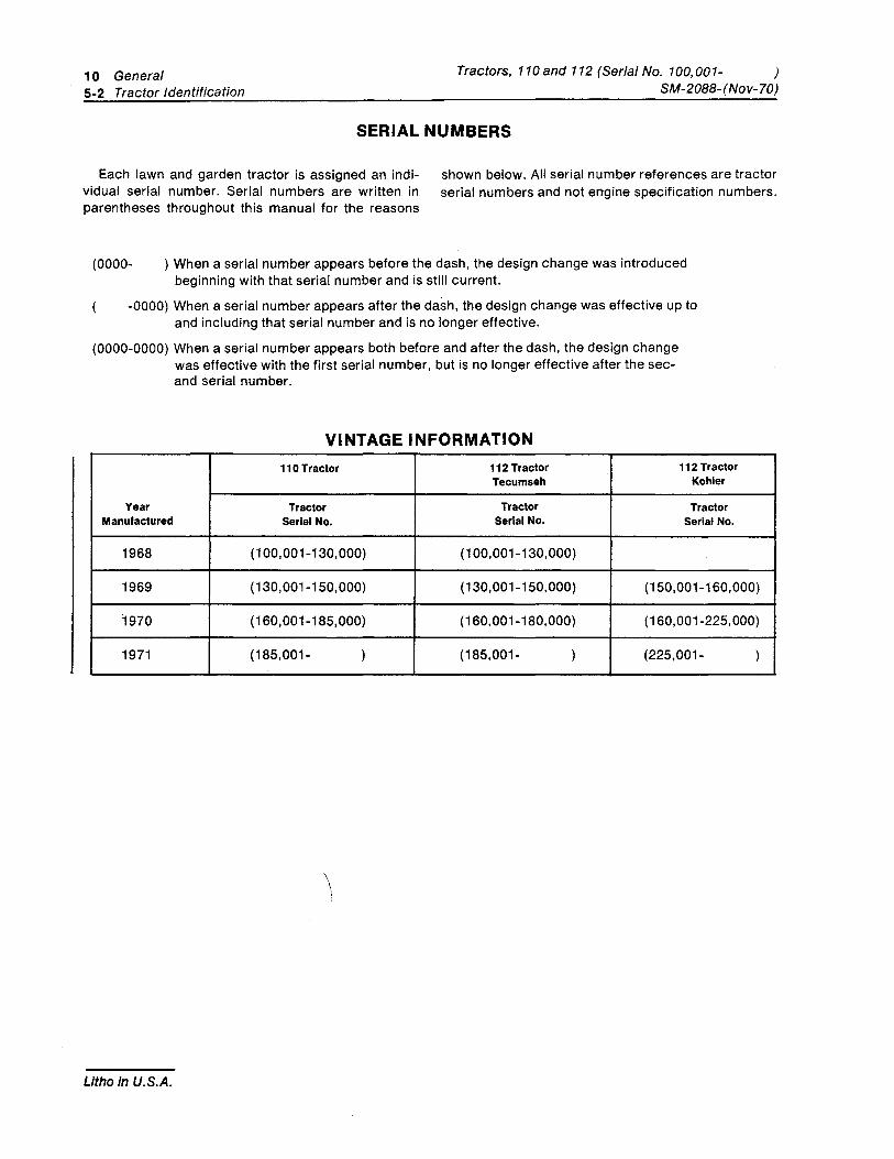
SERIAL NUMBERS
Each lawn and garden tractor is assigned an indi- shown below. All serial number references are tractor vidual serial number. Serial numbers are written in serial numbers and not engine specification numbers. parentheses throughout this manual for the reasons
(0000- ) When a serial number appears before the dash, the design change was introduced beginning with that serial number and is still current.
-0000) When a serial number appears after the dash, the design change was effective up to and including that serial number and is no longer effective.
(0000-0000) When a serial number appears both before and after the dash, the design change was effective with the first serial number, but is no longer effective after the sec-and serial number.
VINTAGE INFORMATION 110 Tractor 112 Tractor
Tecumseh
Year Tractor Tractor Manufactured Serial No. Serial No.
1968 (100,001-130,000) (100,001-130,000)
112 Tractor Kohler
Tractor Serial No.
1969 (130,001-150,000) (130,001-150,000) (150,001-160,000)
1970 (160,001-185,000) (160,001-180,000) (160,001-225,000)
1971 (185,001- ) (185,001- ) (225,001- )
\
Litho in U.S.A.
Tractors, 110and 112 (Serial No. 100,001-SM-2088-(Nov-69)
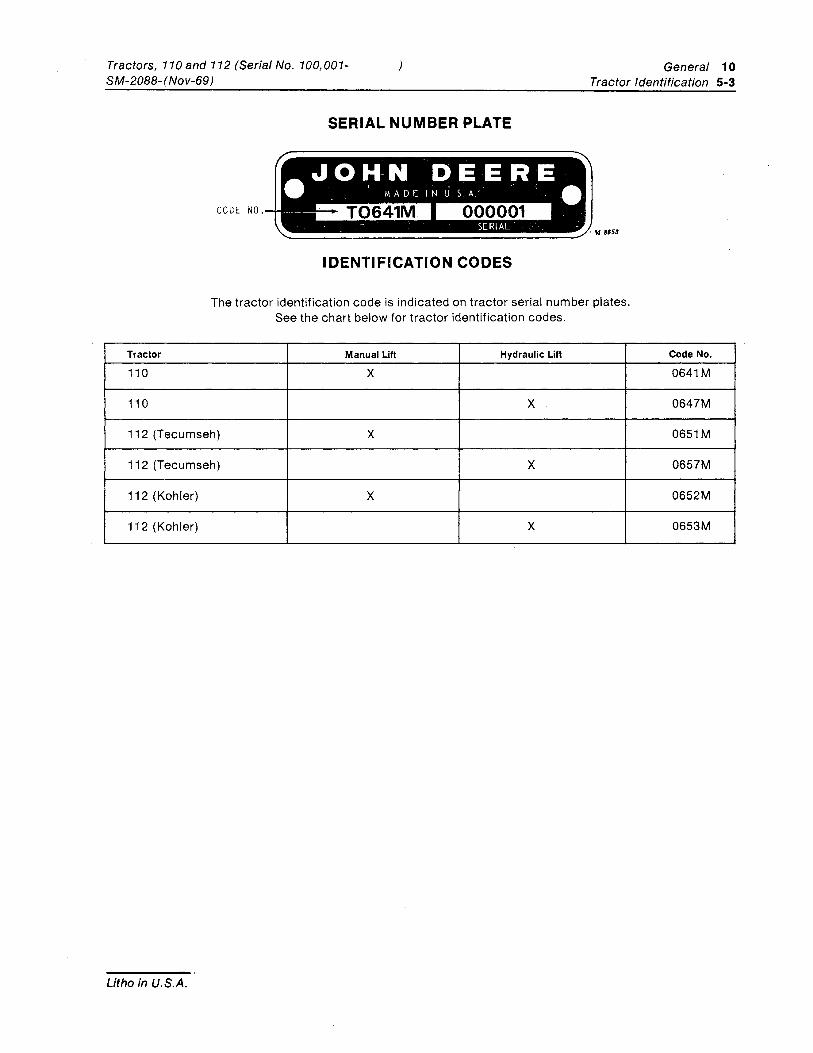
SERIAL NUMBER PLATE
CODE NO
IDENTIFICATION CODES
General 10 Tractor Identification 5-3
The tractor identification code is indicated on tractor serial number plates. See the chart below for tractor identification codes.
Tractor Manual Lift Hydraulic Lift Code No.
110 X 0641M
110 X 0647M
112 (Tecumseh) X 0651M
112 (Tecumseh) X 0657M
112 (Kohler) X 0652M
112 (Kohler) X 0653M
Litho in U.S.A.
10 General Tractors, 110and112 (Serial No. 100,001- ) 5-4 Tractor Identification SM-2088-(Nov-69)
Litho in U.S.A.
Tractors, 110 and 112 (Serial No. 100,001-SM-20BB-(Nov-69)
) General 10 Specifications 10-1
Group 10 SPECIFICATIONS
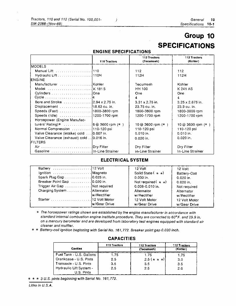
ENGINE SPECIFICATIONS 112 Tractors 112 Tractors
110 Tractors (Tecumseh) (Kohler)
MODELS Manual Lift .................. 110 112 112 Hydraulic Lift ................. 11 OH 112H 112H
ENGINE Manufacturer ................ Kohler Tecumseh Kohler Model ...................... K 181 S HH 100 K 241 AS Cylinders .................... One One One Cycle ....................... 4 4 4 Bore and Stroke .............. 2.94 x 2.75 in. 3.31 x 2.75 in. 3.25 x 2.875 in. Displacement ................ 18.63 cu. in. 23.75 cu. in. 23.9 cu. in. Speeds (Fast) ................ 1800-3800 rpm 1800-3800 rpm 1800-3800 rpm Speeds (Idle) ................ 1200-1700 rpm 1200-1700 rpm 1200-1700 rpm Horsepower (Engine Manufac-turers' Rating)* .............. 8 @ 3600 rpm (* ) 10@ 3600 rpm (* ) 10@ 3600 rpm (* Normal Compression .......... 110-120 psi 110-120 psi 110-120 psi Valve Clearance (intake) cold ... 0.007 in. 0.010 in. 0.010 in. Valve Clearance (exhaust) cold .. 0.016 in. 0.020 in. 0.020 in.
FILTERS Air ......................... Dry Filter Dry Filter Dry Filter Gasoline .................... In-Line Strainer In-Line Strainer I n-Line Strainer
ELECTRICAL SYSTEM
Battery ................... 12 Volt 12 Volt 12 Volt Ignition ................... Magneto Solid State ( * *) Battery-Coil Spark Plug Gap ............. 0.025 in. 0.030 in. 0.020 in. Breaker Point Gap ...... . .. . 0.020 in. Not required ( * *) 0.020 in . Trigger Air Gap ............. Not required 0.006-0.010 in. Not required Charging System ............ Alternator Alternator Alternator
w/Rectifier w/Rectifier w/Rectifier Starter .................... 12 Volt Motor 12 Volt Motor 12 Volt Motor
w/Gear Drive w/Gear Drive w/Gear Drive
* The horsepower ratings shown are established by the engine manufacturer in accordance with standard internal combustion engine institute procedure. They are corrected to 60° F. and 29.9 in. on a mercury barometer and are developed from laboratory test engines equipped with standard air cleaner and muffler. * * Battery-coil ignition beginning with Serial No. 161,772. Breaker point gap 0.020 inch.
CAPACITIES 110 Tractors
Cavities
Fuel Tank - U.S. Gallons 1.75 Crankcase - U.S. Pints 2.5 Transaxle - U.S. Pints 3.5 Hydraulic Lift System - 2.5
U.S. Pints
* * * 3 U.S. pints beginning with Serial No. 161,772.
Litho in U.S.A.
112 Tractors 112 Tractors (Tecumseh) (Kohler)
1.75 1.75 2.5 (* * *) 3.0 3.5 3.5 2.5 2.0
)
10 General Tractors, 110 and 112 (Serial No. 100,001- ) 10-2 Specifications SM-2088- (Nov-69)
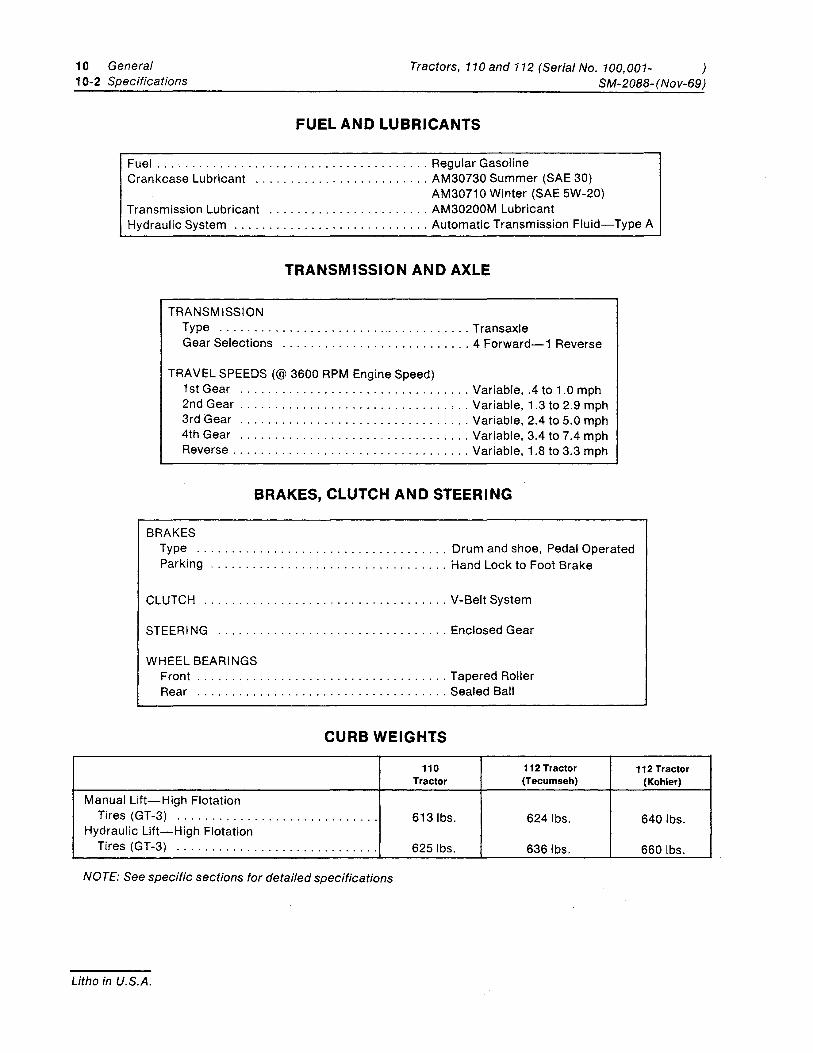
FUEL AND LUBRICANTS
Fuel ....................................... Regular Gasoline Crankcase Lubricant ......................... AM30730 Summer (SAE 30)
AM30710 Winter (SAE 5W-20) Transmission Lubricant ....................... AM30200M Lubricant Hydraulic System ............................ Automatic Transmission Fluid-Type A
TRANSMISSION AND AXLE
TRANSMISSION Type ..................................... Transaxle Gear Selections ........................... 4 Forward-1 Reverse
TRAVEL SPEEDS (@ 3600 RPM Engine Speed) 1 st Gear ................................. Variable, .4 to 1.0 mph 2nd Gear .............................. , .. Variable, 1.3 to 2.9 mph 3rd Gear ................................. Variable, 2.4 to 5.0 mph 4th Gear ................................. Variable, 3.4 to 7.4 mph Reverse .................................. Variable, 1.8 to 3.3 mph
BRAKES, CLUTCH AND STEERI NG
BRAKES Type .................................... Drum and shoe, Pedal Operated Parking .................................. Hand Lock to Foot Brake
CLUTCH ................................... V-Belt System
STEERING ................................. Enclosed Gear
WHEEL BEARINGS Front .................................... Tapered Roller Rear .................................... Sealed Ball
CURB WEIGHTS
110 112 Tractor 112 Tractor Tractor (Tecumseh) (Kohler)
Manual Lift-High Flotation Tires (GT-3) . .. . ... .. . . . . . .. . ......... ... 6131bs. 6241bs. 6401bs .
Hydraulic Lift-High Flotation Tires (GT-3) .. .. ... . .. . ... .. . . . . .. ....... 6251bs. 6361bs. 6601bs .
NOTE: See specific sections for detailed specifications
Litho in U.S.A.
General 10 Tractors, 110and 112 (Serial No. 100,001-SM-2088- (Nov-69) Specifications 10-3
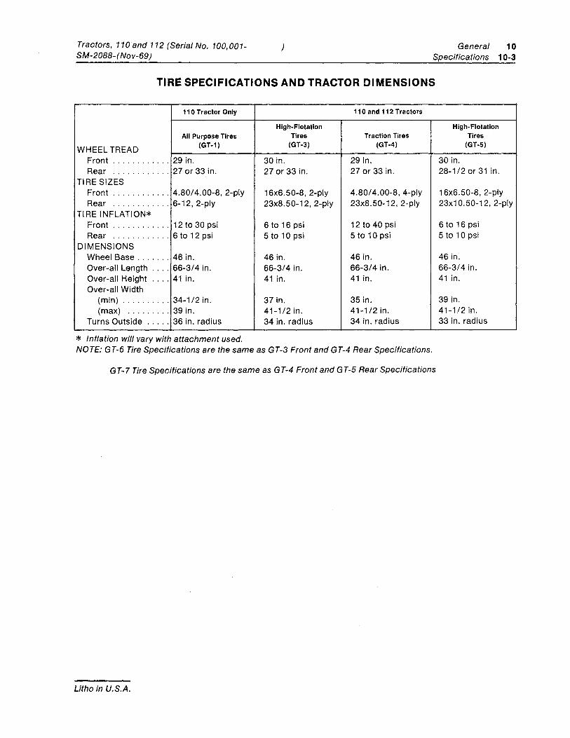
TIRE SPECIFICATIONS AND TRACTOR DIMENSIONS
WHEEL TREAD
110 Tractor Only
All Purpose Tires (GT-1)
Front ............ 29 in. Rear ............ 27 or 33 in.
TIRE SIZES Front ............ 4.80/4.00-8, 2-ply Rear ............ 6-12, 2-ply
TIRE INFLATION* Front ............ 12 to 30 psi Rear ............ 6 to 12 psi
DIMENSIONS Wheel Base ....... 46 in. Over-all Length .... 66-3/4 in. Over-all Height .... 41 in. Over-all Width
(min) .......... 34-1/2 in. (max) ......... 39 in.
Turns Outside ..... 36 in. radius
* Inflation will vary with attachment used.
110 and 112 Tractors
High-Flotation Tires Traction Tires
(GT-3) (GT-4)
30 in. 29 in. 27 or 33 in. 27 or 33 in.
16x6.50-8, 2-ply 4.80/4.00-8, 4-ply 23x8.50-12, 2-ply 23x8.50-12, 2-ply
6 to 16 psi 12 to 40 psi 5 to 10 psi 5 to 10 psi
46 in. 46 in. 66-3/4 in. 66-3/4 in. 41 in. 41 in.
37 in. 35 in. 41-1/2 in. 41-1/2 in. 34 in. radius 34 in. radius
NOTE: GT-6 Tire Specifications are the same as GT-3 Front and GT-4 Rear Specifications.
G T-7 Tire Specifications are the same as G T-4 Front and G T-5 Rear Specifications
Litho in U.S.A.
High-Flotation Tires
(GT-5)
30 in. 28-1/2 or 31 in.
16x6.50-8, 2-ply 23x1 0.50-12, 2-ply
6 to 16 psi 5 to 10 psi
46 in. 66-3/4 in. 41 in.
39 in. 41-1/2 in. 33 in. radius
10 General Tractors, 110 and 112 (Serial No. 100,001- ) 10-4 Specifications SM-2088- (Nov-69)
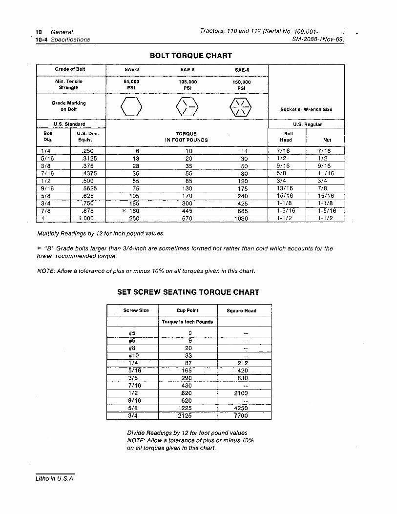
BOLT TORQUE CHART Grade of Bolt SAE-2 SAE-5 SAE-8
Min. Tensile 64,000 105,000 150,000 Strength PSI PSI PSI
Grade Marking 0 (> ? @ on Bolt /\ Socket or Wrench Size
U.S. Standard U.S. Regular
Bolt U.S. Dec. TORQUE Bolt Dia. Equiv. IN FOOT POUNDS Head Nut
1/4 .250 6 10 14 7/16 7/16 5/16 .3125 13 20 30 1/2 1/2 3/8 .375 23 35 50 9/16 9/16 7/16 .4375 35 55 80 5/8 11/16 1/2 .500 55 85 120 3/4 3/4 9/16 .5625 75 130 175 13/16 7/8 5/8 .625 105 170 240 15/16 15/16 3/4 .750 185 300 425 1-1/8 1-1/8 7/8 .875 * 160 445 685 1-5/16 1-5/16 1 1.000 250 670 1030 1-1/2 1-1/2
Multiply Readings by 12 for inch pound values.
* "B" Grade bolts larger than 3/4-inch are sometimes formed hot rather than cold which accounts for the lower recommended torque.
NOTE: Allow a tolerance of plus or minus 10% on all torques given in this chart.
Litho in U.S.A.
SET SCREW SEATING TORQUE CHART
Screw Size Cup Point Square Head
Torque in Inch Pounds
#5 9 --#6 9 --#8 20 --#10 33 --1/4 87 212 5/16 165 420 3/8 290 830 7/16 430 --1/2 .620 2100 9/16 620 --5/8 1225 4250 3/4 2125 7700
Divide Readings by 12 for foot pound values NOTE: Allow a tolerance of plus or minus 10% on all torques given in this chart.
Tractors, 110 and 112 (Serial No. 100,001-SM-2088-(Nov-69)
) General 10 Tune-Up and Adjustment 15-1
Group 15 TUNE-UP AND ADJUSTMENT
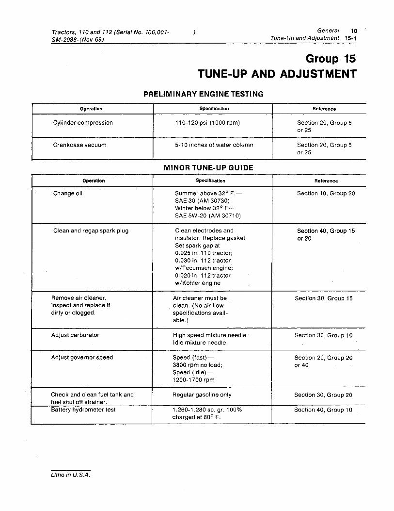
PRELIMINARY ENGINE TESTING
Operation Specification Reference
Cylinder compression 110-120 psi (1000 rpm) Section 20, Group 5 or25
Crankcase vacuum 5-10 inches of water column Section 20, Group 5 or25
MINOR TUNE-UP GUIDE Operation Specification Reference
Change oil Summer above 32° F.- Section 10, Group 20 SAE 30 (AM 30730) Winter below 32° F-SAE 5W-20 (AM 30710)
Clean and regap spark plug Clean electrodes and Section 40, Group 15 insulator. Replace gasket or 20 Set spark gap at 0.025 in. 110 tractor; 0.030 in. 112 tractor w/Tecumseh engine; 0.020 in. 112 tractor wi Kohler engine
Remove air cleaner, Air cleaner must be Section 30, Group 15 inspect and replace if clean. (No air flow dirty or clogged. specifications avail-
able.)
Adjust carburetor High speed mixture needle Section 30, Group 10 Idle mixture needle
Adjust governor speed Speed (fast)- Section 20, Group 20 3800 rpm no load; or40 Speed (idle)-1200-1700 rpm
Check and clean fuel tank and Regular gasoline only Section 30, Group 20 fuel shut off strainer. Battery hydrometer test 1.260-1.280 sp. gr. 100% Section 40, Group 10
charged at 80° F.
Litho in U.S.A.
10 General Tractors 110and 112(Serial No. 100,001- ) 15-2 Tune-Up and Adjustment SM-2088-(Nov-69)
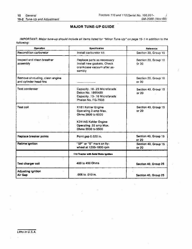
MAJOR TUNE-UP GUIDE
IMPORTANT: Major tune-up should include all items listed for "Minor Tune-Up" on page 15-1 in addition to the following:
Operation Specification Reference Recondition carburetor Install carburetor kit Section 30, Group 10
I nspect and clean breather Replace parts as necessary Section 20. Group 10 assembly Install new gaskets. Check Or 30
crankcase vacuum after as-sembly
Remove shrouding, clean engine Section 20. Group 10 and cylinder head fins .................... or 30
Test condenser Capacity .18-.23 Microfarads Section 40. Group 15 Delco No. 1965489 or 20 Capacity .13-.16 Microfarads Phelon No. FG-7533
Test coil K181 Kohler Engine Section 40, Group 15 Operating 3 amp Max. or 20 Ohms 3800 to 6000
K241 AS Kohler Engine Operating .55 amp Max. Ohms 5500 to 9500
Replace breaker pOints Point gap 0.020 in. Section 40, Group 15 or 20
Retime ignition "SP" or "S" mark on fly- Section 40, Group 15 wheel at 1200-1800 rpm or 20
112 Tractor with Solid Stat. Ignition
Test charger coil 400 to 450 Ohms Section 40, Group 25
Adjusting Ignition Air Gap .006 to .010 in. Section 40, Group 25
Litho in U.S.A.
Tractors, 110 and 112 (Serial No. 100,001-SM-2088- (Nov-69)
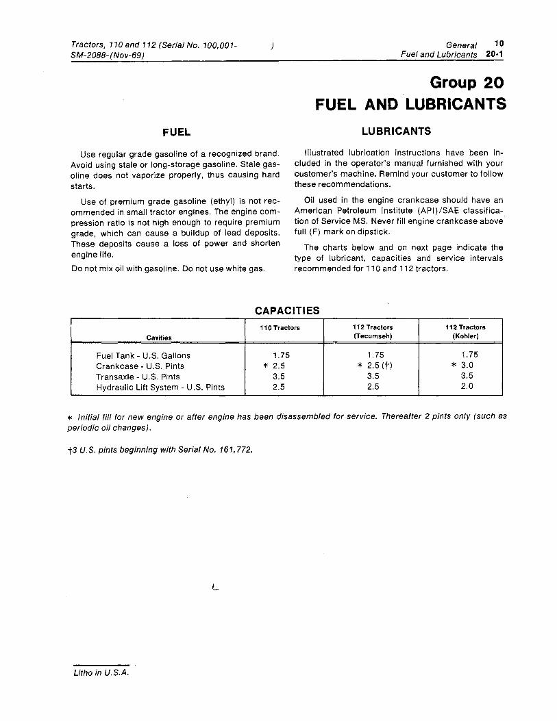
FUEL
)
Use regular grade gasoline of a recognized brand. Avoid using stale or long-storage gasoline. Stale gas-oline does not vaporize properly, thus causing hard starts.
Use of premium grade gasoline (ethyl) is not rec-ommended in small tractor engines. The engine com-pression ratio is not high enough to require premium grade, which can cause a buildup of lead deposits. These deposits cause a loss of power and shorten engine life. Do not mix oil with gasoline. Do not use white gas.
General 10 Fuel and Lubricants 20-1
Group 20 FUEL AND LUBRICANTS
LUBRICANTS
Illustrated lubrication instructions have been in-cluded in the operator's manual furnished with your customer's machine. Remind your customer to follow these recommendations.
Oil used in the engine crankcase should have an American Petroleum Institute (API)/SAE classifica-tion of Service MS. Never fill engine crankcase above full (F) mark on dipstick.
The charts below and on next page indicate the type of lubricant, capacities and service intervals recommended for 110 and 112 tractors.
CAPACITIES I
110 Tractors 112 Tractors 112 Tractors Cavities (Tecumseh) (Kohler)
Fuel Tank - U.S. Gallons 1.75 1.75 1.75 Crankcase - U.S. Pints * 2.5 * 2.5 (t) * 3.0 Transaxle - U.S. Pints 3.5 3.5 3.5 Hydraulic Lift System - U.S. Pints 2.5 2.5 2.0
* Initial fill for new engine or after engine has been disassembled for service. Thereafter 2 pints only (such as periodic oil changes).
t3 U.S. pints beginning with Serial No. 161,772.
L
Litho in U.S.A.
10 General Tractors, 110 and 112(Serial No. 100,001 ) 20-2 Fuel and Lubriants
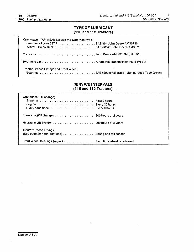
TYPE OF LUBRICANT (110 and 112 Tractors)
Crankcase - (API)/SAE Service MS Detergent type Summer - Above 32° F ...................... SAE 30 - John Deere AM30730 Winter - Below 32°F ........................ SAE 5W-20 John Deere AM30710
Transaxle .................................. John Deere AM30200M (SAE 90)
SM-2088- (Nov-69)
Hydraulic Lift ................................ Automatic Transmission Fluid Type A
Tractor Grease Fittings and Front Wheel Bearings ................................. SAE (Seasonal grade) Multipurpose-Type Grease
Crankcase (Oil change)
SERVICE INTERVALS (110 and 112 Tractors)
Break-in ................................. First 2 hours Regular .................................. Every 25 hours Dusty conditions ........................... Every 8 hours
Transaxle (Oil change) ........................ 200 hours or 2 years
Hydraulic Lift System ......................... 200 hours or 2 years
Tractor Grease Fittings (See page 20-4 for locations) ................... Spring and fall season
Front Wheel Bearings (repack) ................. Each time wheel is removed
Litho in U.S.A.
Tractors, 110 and 112 (Serial No. 100,001-SM-2088-(Nov-70)
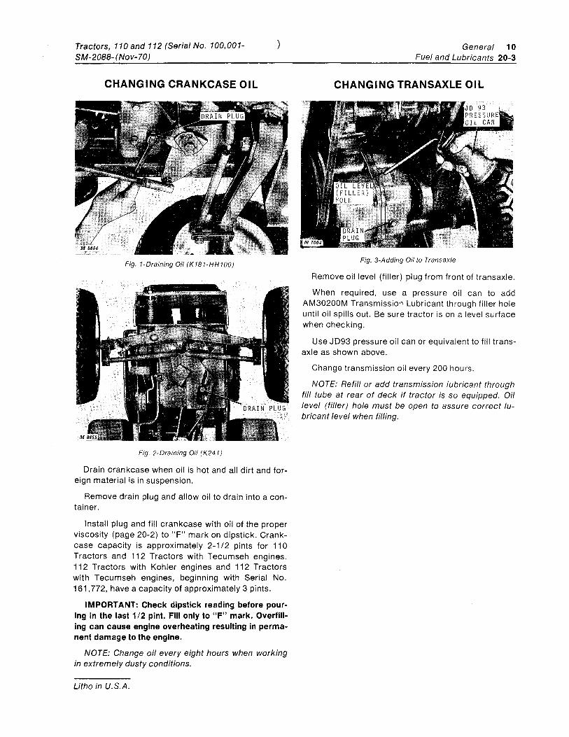
CHANGING CRANKCASE OIL
Fig. 1-Draining Oil (K1B1-HH100)
Fig. 2-Draining Oil (K241)
)
Drain crankcase when oil is hot and all dirt and for-eign material is in suspension.
Remove drain plug and allow oil to drain into a con-tainer.
Install plug and fill crankcase with oil of the proper viscosity (page 20-2) to "F" mark on dipstick. Crank-case capacity is approximately 2-112 pints for 110 Tractors and 112 Tractors with Tecumseh engines. 112 Tractors with Kohler engines and 112 Tractors with Tecumseh engines, beginning with Serial No. 161,772, have a capacity of approximately 3 pints.
IMPORTANT: Check dipstick reading before pour-ing in the last 112 pint. Fill only to "F" mark. Overfill-ing can cause engine overheating resulting in perma-nent damage to the engine.
NOTE: Change oil every eight hours when working in extremely dusty conditions.
Litho in U.S.A.
General 10 Fuel and Lubricants 20-3
CHANGING TRANSAXLE OIL
Fig. 3-Adding Oil to Transaxle
Remove oil level (filler) plug from front of transaxle.
When required, use a pressure oil can to add AM30200M Transmission Lubricant through filler hole until oil spills out. Be sure tractor is on a level surface when checking.
Use JD93 pressure oil can or equivalent to fill trans-axle as shown above.
Change transmission oil every 200 hours.
NOTE: Refill or add transmission lubricant through fill tube at rear of deck if tractor is so equipped. Oil level (filler) hole must be open to assure correct lu-bricant level when filling.
10 General 20-4 Fuel and Lubricants
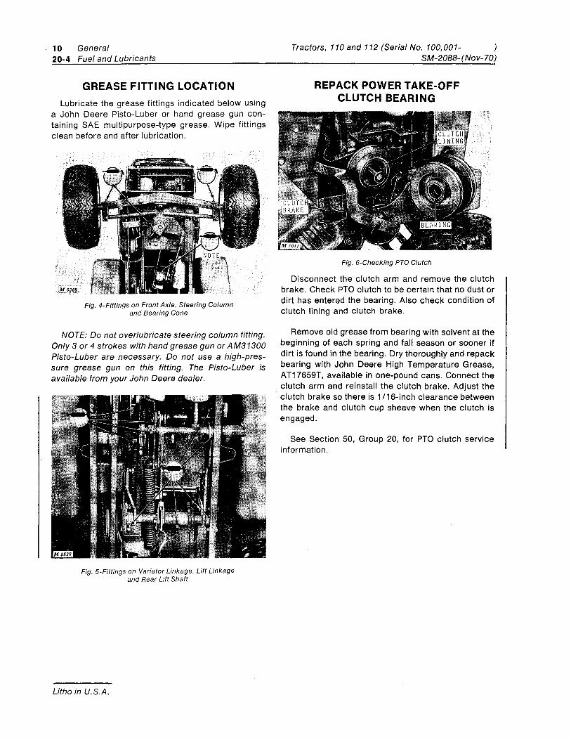
GREASE FITTING LOCATION Lubricate the grease fittings indicated below using
a John Deere Pisto-Luber or hand grease gun con-taining SAE mUltipurpose-type grease. Wipe fittings clean before and after lubrication.
Fig. 4-Fittings on Front Axle, Steering Column and Bearing Cone
NOTE: Do not overlubricate steering column fitting. Only 3 or 4 strokes with hand grease gun or AM31300 Pisto-Luber are necessary. Do not use a high-pres-sure grease gun on this fitting. The Pisto-Luber is available from your John Deere dealer.
Fig. 5-Fittings on Variator Linkage, Lift Linkage and Rear Lift Shaft
Litho in U.S.A.
Tractors, 110and 112 (Serial No. 100,001- ) SM-2088- (Nov-70)
REPACK POWER TAKE-OFF CLUTCH BEARING
Fig. 6-Checking PTO Clutch
Disconnect the clutch arm and remove the clutch brake. Check PTO clutch to be certain that no dust or dirt has entered the bearing. Also check condition of clutch lining and clutch brake.
Remove old grease from bearing with solvent at the beginning of each spring and fall season or sooner if dirt is found in the bearing. Dry thoroughly and repack bearing with John Deere High Temperature Grease, AT17659T, available in one-pound cans. Connect the clutch arm and reinstall the clutch brake. Adjust the clutch brake so there is 1 116-inch clearance between the brake and clutch cup sheave when the clutch is engaged.
See Section 50, Group 20, for PTO clutch service information.
Section 20 ENGINE
Group 5 GENERAL INFORMATION
KOHLER ENGINES FOR 110 AND 112 TRACTORS TABLE OF CONTENTS-KOHLER ENGINES
GROUP 5 - GENERAL INFORMATION-KOHLER ENGINES
Page Description .. . . . . . . . . . . . .. . . . . . . . . . . . . . 5-4 Engine Analysis ......................... 5-7
Preliminary Engine Checks .............. 5-7 Preliminary Engine Tests ............... 5-7
Diagnosing Malfunctions ................. 5-9
GROUP 10 - CYLINDER HEAD, VALVES AND BREATHER - KOHLER ENGINES
General Information . . . . . . . . . . . . . . . . . . .. 10-1 Valve Analysis ......................... 10-2 Repair . . . . . . . . . . . . . . . . . . . . . . . . . . . . . .. 10-3
Removing Valves .................... 10-4 I nspecting Cylinder Head .............. 10-4 I nspecting Breather .................. 10-5 Testing Valve Springs ................. 10-5 Inspecting Valves .................... 10-5 Reconditioning or Replacing Valves ...... 10-6 Replacing Valve Guides ............... 10-7 Replacing Exhaust Valve Insert ......... 10-8 Installing Intake Valve Insert ........... 10-8 Checking Valve Clearance ............. 10-8
Installation ........................... 10-9 Installing Valve Springs. Retainers
and Keepers ...................... 10-9 Assembling Breather ................. 10-9 I nstalling Cylinder Head . . . . . . . . . . . . .. 10-10 I nstalling Carburetor ................. 10-10
Specifications . . . . . . . . . . . . . . . . . . . . . . . . 10-11 Table of Clearances ................. 10-11 Torque for Hardware ................. 10-11 Tune-Up Data ...................... 10-11
Special Tools. . . . . . . . . . . . . . . . . . . . . . . .. 10-12
GROUP 15 - PISTON, CRANKSHAFT, MAIN BEARI NGS AND FLYWHEEL -KOHLER ENGINES
General Information ... . . . . . . . . . . . . . . . .. 15-1 Repair ............................... 15-2
Removing Engine from Tractor .......... 15-3
Litho in U.S.A.
Page
Disassembling Kohler K181S Engine ..... 15-3 Disassembling Kohler K241 AS Engine .... 15-3 I nspecting Balance Gear Stub Shaft ..... 15-4 I nspecting Balance Gear and Bearing . . .. 15-4 Removing Piston Rings. . . . . . . . . . . . . . .. 15-4 Analyzing Piston Ring Wear ............ 15-5 I nspecting Piston .................... 15-6 Analyzing Piston Wear ................ 15-8 I nspecting and Repairing Block . . . . . . .. 15-10 Deglazing Cylinder Bore. . . . . . . . . . . . .. 15-10 Boring Cyl inder Block . . . . . . . . . . . . . . .. 15-10 I nspecting Crankshaft ............... 15-11 Analyzing Connecting Rod and Cap Wear 15-11 I nspecting Main Bearings. . . . . . . . . . . .. 15-12 Analyzing Bearing Wear . . . . . . . . . . . . .. 15-12 I nspecting Camshaft ................. 15-13
Installation .......................... 15-13 I nstalling Balance Gears ............. 15-13 Installing Crankshaft with Timing Tool
(Kohler K241AS Engine) ........... 15-14 Installing Crankshaft without Timing
Tool (Kohler K241AS Engine) ...... " 15-15 Installing Crankshaft (Kohler K181S
Engine) ......................... 15-16 Assembling Bearing. Bearing Plate and
Oil Seals (Kohler K181S Engine) ..... Assembling Bearing. Bearing Plate and
Oil Seals (Kohler K241AS Engine) .... 15-16 Installing Bearing, Bearing Plate and
Oil Seals ........................ 15-17 Assembling Connecting Rod and Piston .. 15-17 Checking Piston Ring End Gap ......... 15-18 I nstalling Rings and Piston .... . . . . . . .. 15-18 Attaching Rod to Crankshaft ......... " 15-19 Installing Oil Pan on Block ............ 15-19 I nstalling Flywheel .................. 15-19 Installing Shrouding ................. 15-20 I nstalling Exterior Components ........ 15-20
Specifications ........................ 15-21 Torques for Hardware ................ 15-22 Tune-Up Data ...................... 15-22
Special Tools ......................... 15-22
20 Engine Tractors, 110 and 112 (Serial No. 100,001- ) 5-2 General Information - Kohler SM-2088- (Nov-69)
TABLE OF CONTENTS-CONTINUED
Page
GROUP 20 - CAMSHAFT, TAPPETS AND GOVERNOR - KOHLER ENGINES
General Information .. . . . . . . . . . . . . . . . . .. 20-1 Automatic Compression Release
Camshaft. . . . . . . . . . . . . . . . . . . . . . . .. 20-2 Repair . . . . . . . . . . . . . . . . . . . . . . . . . . . . . . . 20-3
Removing Camshaft and Tappets ........ 20-3 Removing Governor .................. 20-4 I nspecting Camshaft. . . . . . . . . . . . . . . . .. 20-4 I nspecting Governor Gear ............. 20-4
Page
Installation ........................... 20-4 Installing Governor ................... 20-4 Installing Camshaft ................... 20-5 Connecting Governor Arm to
Carburetor ........................ 20-6 I nstalling Governor Arm ............... 20-6 Adjustment ......................... 20-7
Governor Speed Adjustment ......... 20-7 Specifications . . . . . . . . . . . . . . . . . . . . . .. 20-7
Table of Engine Clearances .......... 20-7 Special Tools ........................ 20-7
TABLE OF CONTENTS-TECUMSEH ENGINE (Serial No.1 00,001-161,771)
GROUP 25 - GENERAL INFORMATION-TECUMSEH ENGINE
Page
Description ... . . . . . . . . . . . . . . . . . . . . . . .. 25-1 Engine Analysis ........................ 25-2
Preliminary Engine Checks ............. 25-2 Preliminary Engine Tests .............. 25-2
Diagnosing Malfunctions ................ 25-3
GROUP 30 - CYLINDER HEAD, VALVES AND BREATHER-TECUMSEH ENGINE
General Information .. . . . . . . . . . . . . . . . . . . 30-1 Valve Analysis ......................... 30-2 Repair . . . . . . . . . . . . . . . . . . . . . . . . . . . . . . . 30-3
Removing Valves .................... 30-4 Inspecting Cylinder Head .............. 30-4 I nspecting Breather .................. 30-5 Testing Valve Springs ................. 30-5 Inspecting Valves .................... 30-5 Reconditioning or Replacing Valves ...... 30-6 Reaming Valve Guides ................ 30-7 Removing and I nstalling Exhaust
Valve Seat Insert .................. 30-8 Checking Valve Clearance ............. 30-8
Installation ........................... 30-9 I nstalling Valve Springs, Retainers
and Keeper Pins ................... 30-9 Installing Breather ................... 30-9
Litho in U.S.A.
Page
Installing Cylinder Head ............... 30-9 I nstalling Carburetor ................. 30-10 Installing Muffler. . . . . . . . . . . . . . . . . . . . 30-10 Checking Air Filter .................. 30-10 Checking Spark Plug Gap ............. 30-10 Setting Ignition Module Air Gap ........ 30-10 I nstalling Hydraulic System ........... 30-10
Specifications . . . . . . . . . . . . . . . . . . . . . . . . 30-11 Table of Engine Clearances ........... 30-11 Torque for Hardware ................. 30-11 Tune-Up Data ...................... 30-11
Special Tools ......................... 30-12
GROUP 35 - PISTON, CRANKSHAFT, MAIN BEARINGS AND FLYWHEEL-TECUMSEH ENGINE
General Information . . . . . . . . . . . . . . . . . . . . 35-1 Repair . . . . . . . . . . . . . . . . . . . . . . . . . . . . . . . 35-2
Removing Engine from Tractor .......... 35-3 Disassembling Engine ................ 35-3 Removing Cylinder Ridge .............. 35-3 Pulling Flywheel ..................... 35-3 Removing Cylinder Cover .............. 35-3 Removing Crankshaft ................. 35-4 Removing Piston Rings ................ 35-4 Analyzing Piston Ring Wear ............ 35-4 I nspecting Piston .................... 35-6 Analyzing Piston Wear ................ 35-8
Tractors, 110 and 112 (Serial No. 100,001-SM-2088-Nov-69 )
}
Page
I nspecting Crankshaft ............... 35-10 Analyzing Connecting Rod and Cap Wear 35-10 I nspecting and Repairing Block ........ 35-11 Deglazing Cylinder Bore .............. 35-11 Boring Cylinder Block ................ 35-11 I nspecting Camshaft. . . . . . . . . . . . . . . . . 35-11 I nspecting Main Bearings ............. 35-12 Analyzing Bearing Wear .............. 35-12
Installation .......................... 35-13 Installing Crankshaft ................. 35-13 Assembling Connecting Rod and
Piston .......................... 35-13 Checking Piston Ring End Gap ......... 35-13 I nstalling Rings on Piston ............. 35-14 Installing Connecting Rod and Piston .... 35-14 Attaching Rod to Crankshaft. . . . . . . . . . . 35-15 I nstalling Tappets and Camshaft ....... 35-15 I nstalling Cylinder Cover .............. 35-15 Checking Crankshaft End Clearance .... 35-16 Installing Seals ..................... 35-17 I nstalling Flywheel .................. 35-17 I nstalling External Components ........ 35-17
Specifications . . . . . . . . . . . . . . . . . . . . . . . . 35-18 Torque for Hardware ................. 35-18 Table of Engine Clearances ........... 35-18
Special Tools ......................... 35-19
Litho in U.S.A.
Engine 20 General Information - Kohler 5-3
GROUP 40 - CAMSHAFT, TAPPETS AND GOVERNOR-TECUMSEH ENGINE
Page
General Information .. . . . . . . . . . . . . . . . . . . 40-1 Repair . . . . . . . . . . . . . . . . . . . . . . . . . . . . . . . 40-3
Removing Camshaft and Tappets ........ 40-3 Removing Governor Gear . . . . . . . . . . . . . . 40-3 Removing Governor Rod ............... 40-4 I nspecting Camshaft. . . . . . . . . . . . . . . . . . 40-4 I nspecting Governor Gear ............. 40-4 I nspecting Governor Rod .............. 40-4 I nspecting Governor Shaft ............. 40-5
Installation ........................... 40-5 Installing Governor Shaft .............. 40-5 Installing Governor Gear and Spool ...... 40-5 Installing Tappets and Camshaft ........ 40-6 Installing Governor Rod and Lever ....... 40-6 I nstalling Governor Linkage ............ 40-6
Adjustment ........................... 40-7 Adjusting Governor Stop Screw ......... 40-7 Adjusting Cable and Conduit ........... 40-7
Specifications . . . . . . . . . . . . . . . . . . . . . . . . . 40-7
20 Engine Tractors, 110and 112 (Serial No. 100,001- ) 5-4 General Information - Kohler SM-2088- (Nov-69)
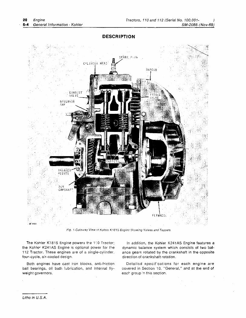
DESCRIPTION
...................••..
.
CYLIND R HEAD
FLYWHEEL
M 8501
Fig. 1-Cutaway View of Kohler K181S Engine Showing Valves and Tappets
The Kohler K181 S Engine powers the 110 Tractor; the Kohler K241 AS Engine is optional power for the 112 Tractor. These engines are of a single-cylinder, four-cycle, air-cooled design.
Both engines have cast iron blocks, anti-friction ball bearings, oil bath lubrication, and internal fly-weight governors.
Litho in U.S.A.
In addition, the Kohler K241 AS Engine features a dynamic balance system which consists of two bal-ance gears rotated by the crankshaft in the opposite direction of crankshaft r0tation.
Detailed specifications for each engine are covered in Section 10, "General," and at the end of each group in this section.
Tractors, 110 and 112 (Serial No. 100,001-SM-2088- (Nov-69)
M 5558
Engine 20 General Information - Kohler 5-5
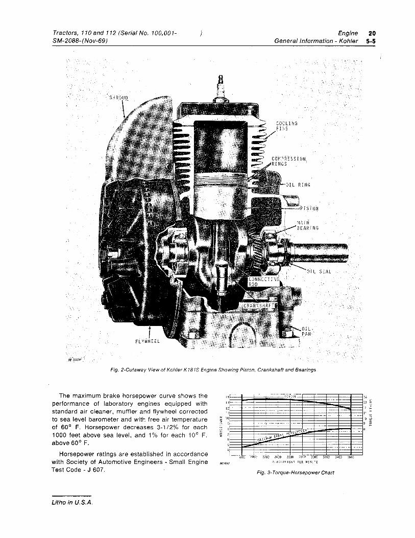
Fig. 2-Cutaway View of Kohler K181S Engine Showing Piston, Crankshaft and Bearings
The maximum brake horsepower curve shows the performance of laboratory engines equipped with standard air cleaner, muffler and flywheel corrected to sea level barometer and with free air temperature of 60° F. Horsepower decreases 3-1/2% for each 1000 feet above sea level, and 1% for each 10° F. above 60° F.
Horsepower ratings are established in accordance with Society of Automotive Engineers - Small Engine Test Code - J 607.
Litho in U.S.A.
4
3
2 1 0 9
8 7 6
S 4
M5653
TORQUE 1 1 1 1 1 9
8
1800 2000 2200 2400 2600 2800 3000 3200 3400 3600 REVOLUTIONS PER MINUTE
Fig. 3- Torque-Horsepower Chart
20 Engine Tractors, 110 and 112 (Serial No. 100,001- ) 5-6 General Information - Kohler SM-2088- (Nov-69)
DESCRIPTION-Continued
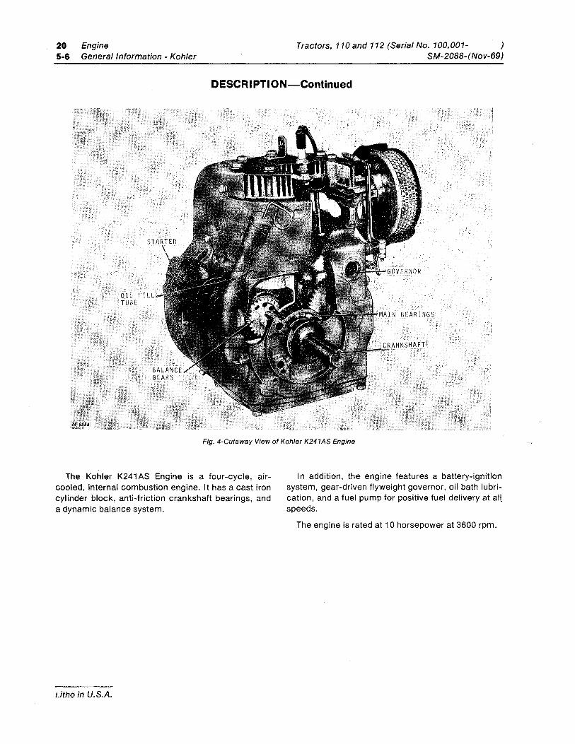
Fig. 4-Cutaway View of Kohler K241AS Engine
The Kohler K241 AS Engine is a four-cycle, air-cooled, internal combustion engine. It has a cast iron cylinder block, anti-friction crankshaft bearings, and a dynamic balance system.
Litho in U.S.A.
In addition, the engine features a battery-ignition system, gear-driven flyweight governor, oil bath lubri-cation, and a fuel pump for positive fuel delivery at all. speeds.
The engine is rated at 10 horsepower at 3600 rpm.
Tractors, 110and 112 (Serial No. 100,001-SM-2088-(Nov-69)
) Engine 20 General Information - Kohler 5-7
ENGINE ANALYSIS
PRELIMINARY ENGINE CHECKS A complete diagnosis guide of engine malfunctions
begins on page 5-9. However, the majority of engine trouble reports are of a minor non-chronic nature and are usually due to electrical or fuel system difficulties. First make the checks listed below to isolate the ma-jority of engine problems.
M 850Z
. '.
1/4" --_=Ifr=J=6 --u
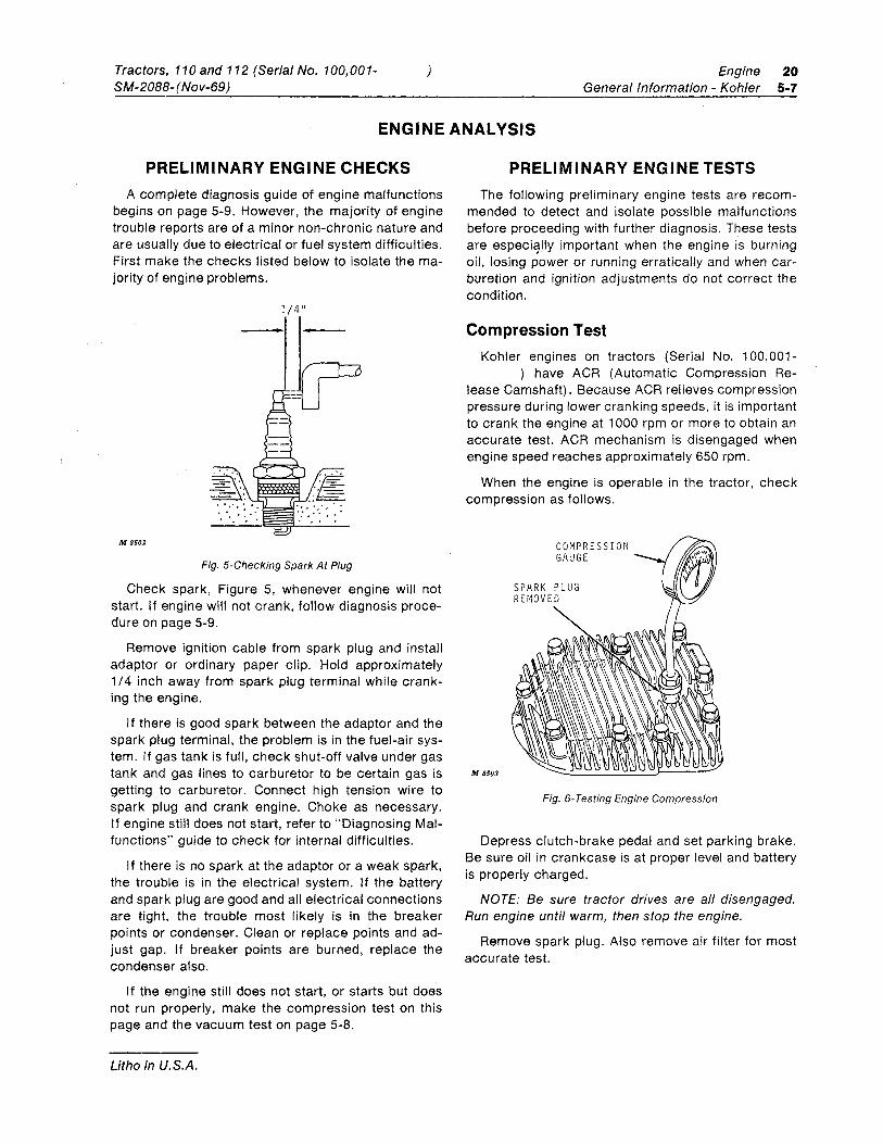
Fig. 5-Checking Spark At Plug
Check spark, Figure 5, whenever engine will not start. If engine will not crank, follow diagnosis proce-dure on page 5-9.
Remove ignition cable from spark plug and install adaptor or ordinary paper clip. Hold approximately 1/4 inch away from spark plug terminal while crank-ing the engine.
I f there is good spark between the adaptor and the spark plug terminal, the problem is in the fuel-air sys-tem. If gas tank is full, check shut-off valve under gas tank and gas lines to carburetor to be certain gas is getting to carburetor. Connect high tension wire to spark plug and crank engine. Choke as necessary. If engine still does not start, refer to "Diagnosing Mal-functions" guide to check for internal difficulties.
If there is no spark at the adaptor or a weak spark, the trouble is in the electrical system. If the battery and spark plug are good and all electrical connections are tight, the trouble most likely is in the breaker points or condenser. Clean or replace points and ad-just gap. If breaker points are burned, replace the condenser also.
If the engine still does not start, or starts but does not run properly, make the compression test on this page and the vacuum test on page 5-8.
Litho in U.S.A.
PRELIMINARY ENGINE TESTS The following preliminary engine tests are recom-
mended to detect and isolate possible malfunctions before proceeding with further diagnosis. These tests are important when the engine is burning oil, losing power or running erratically and when car-buretion and ignition adjustments do not correct the condition.
Compression Test Kohler engines on tractors (Serial No. 100,001-
) have ACR (Automatic Compression Re-lease Camshaft). Because ACR relieves compression pressure during lower cranking speeds, it is important to crank the engine at 1000 rpm or more to obtain an accurate test. ACR mechanism is disengaged when engine speed reaches approximately 650 rpm.
When the engine is operable in the tractor, check compression as follows.
M 8503
COMPRESSION GAUGE
Fig. 6- Testing Engine Compression
Depress clutch-brake pedal and set parking brake. Be sure oil in crankcase is at proper level and battery is properly charged.
NOTE: Be sure tractor drives are all disengaged. Run engine until warm, then stop the engine.
Remove spark plug. Also remove air filter for most accurate test.
20 Engine 5-8 General Information - Kohler
Compression Test-Continued
Set throttle and choke valve in wide open position by raising throttle lever, and lowering choke lever.
Hold compression gauge firmly in spark plug open-ing, Figure 6. Crank engine at 1000 rpm and observe reading. Repeat test to verify readings.
A starter rope can be used if 650 rpm or more can-not be reached by using the electric starter.
To use starter rope procedure, wind a number of turns of 1/4-inch rope around PTO sheave opposite the direction of engine rotation. Pull rope firmly and observe reading. Repeat test until readings are con-sistent.
Test Conclusions
An engine in top operating condition will read 110 to 120 psi when engine is cranked approximately 1000 rpm.
A compression test above 120 psi, indicates exces-sive carbon deposits in the combustion chamber or on the piston.
A reading lower than 100 psi indicates leakage at the cylinder head gasket, piston rings or valves. The engine should be reconditioned if compression falls below 90 psi.
To determine whether the rings or the valves are at fault, pour about one tablespoonful of heavy oil into the spark plug hole. Crank the engine several revolu-tions to spread the oil and repeat the compression test.
The oil will temporarily seal leakage around the pis-ton rings. If the same approximate compression read-ing is obtained, the rings are satisfactory, but the valves are leaking or the piston is damaged. If the compression has increased considerably over the original readings, there is leakage past the rings.
Crankcase Vacuum Test The crankcase breather maintains a partial vac-
uum in the crankcase when the engine is operating properly.
Litho in U.S.A.
Tractors, 110 and 112 (Serial No. 100,001- )
MEASURE DIFFERENCE BETWEEN COLUMNS
M 8504
SM-2088- (Nov-69)
P R E S S U R E
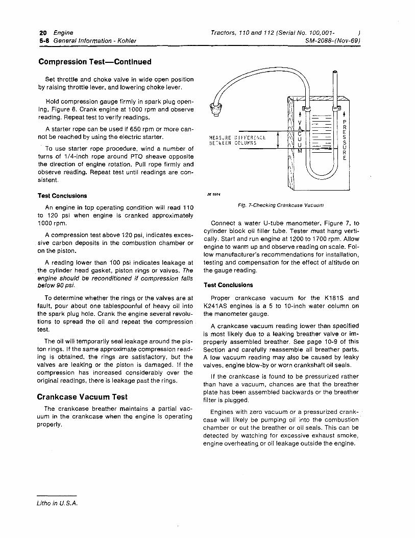
Fig. 7-Checking Crankcase Vacuum
Connect a water U-tube manometer, Figure 7, to cylinder block oil filler tube. Tester must hang verti-cally. Start and run engine at 1200 to 1700 rpm. Allow engine to warm up and observe reading on scale. Fol-low manufacturer's recommendations for installation, testing and compensation for the effect of altitude on the gauge reading.
Test Conclusions
Proper crankcase vacuum for the K181 Sand K241 AS engines is a 5 to 10-inch water column on the manometer gauge.
A crankcase vacuum reading lower than specified is most likely due to a leaking breather valve or im-properly assembled breather. See page 10-9 of this Section and carefully reassemble all breather parts. A low vacuum reading may also be caused by leaky valves, engine blow-by or worn crankshaft oil seals.
If the crankcase is found to be pressurized rather than have a vacuum, chances are that the breather plate has been assembled backwards or the breather filter is plugged.
Engines with zero vacuum or a pressurized crank-case will likely be pumping oil into the combustion chamber or out the breather or oil seals. This can be detected by watching for excessive exhaust smoke, engine overheating or oil leakage outside the engine.
Tractors, 110and 112 (Serial No. 100,001-SM-2088- (Nov-69)
) Engine 20 General Information - Kohler 5-9
DIAGNOSING MALFUNCTIONS
Engine Will Not Crank Transaxle not in neutral.
Battery discharged or defective.
Neutral-start switch and bracket loose or not properly adjusted.
PTO drive engaged.
Defective safety switch (es) .
Defective starter.
Defective solenoid.
Loose electrical connections.
Defective key switch.
Engine seized.
Engine Starts Hard Spark plug pitted or fouled.
Breaker points worn, pitted or out of adjust-ment.
High tension wire shorted.
High tension wire loose at spark plug or coil.
Loose electrical connections.
Restricted gas tank vent.
Clogged fuel line or air lock.
Broken choke cable.
Throttle cable not properly adjusted.
Dirt or water in fuel system.
High speed and idle mixture needles not properly adjusted.
Wrong valve clearance.
Leaking head gasket.
Restricted exhaust system.
Low compression.
Litho in U.S.A.
Engine
Engine Starts But Fails To Keep Running Restricted gas tank vent.
High speed and idle mixture needles not properly adjusted.
Broken choke cable.
Dirt or water in fuel system.
Carburetor float not properly adjusted or float valve leaking.
High tension wire loose at spark plug or coil.
High tension wire shorted.
Breaker points not properly adjusted.
Loose electrical connections.
Faulty condenser.
Excessive engine load.
Engine Cranks But Will Not Start Empty gas tank.
Restricted gas tank vent.
Fuel shut-off valve closed (valve below gas tank).
Clogged, restricted or air-locked fuel line.
Defective ignition module (Tecumseh HH100 engine) .
Breaker pOints worn or pitted.
Spark plug fouled or pitted.
Incorrect spark plug.
Battery not fully charged.
Loose electrical connections.
High speed and idle mixture needles not prop-erly adjusted.
Faulty condenser.
Defective ignition coil.
Dirt in fuel system. Frayed electrical wire(s) causing ground(s).
20 5-10
Engine General Information - Kohler
Tractors, 110and 112 (Serial No. 100,001- ) SM-2088- (Nov-69)
DIAGNOSING MALFUNCTIONS-Continued
Engine Runs But Misses High tension wire loose from spark plug or coil.
Breaker points out of adjustment or worn and pitted.
Spark plug fouled, pitted or gap incorrect.
Incorrect spark plug.
Loose electrical connections. Carburetor float not properly adjusted or float valve leaking.
Dirt or water in fuel system.
Wrong valve clearance.
Faulty coil.
Engine Misses Under Load Spark plug fouled, pitted or gap incorrect.
High speed and idle mixture needles not properly adjusted.
Incorrect spark plug.
Breaker pOints out of adjustment or worn and pitted.
Ignition out of time.
Dirt or water in fuel system.
Stale fuel.
Engine Will Not Idle I die speed too low.
High speed and idle mixture needles not properly adjusted.
Dirt or water in fuel system.
Restricted gas tank vent.
Spark plug fouled, pitted or gap incorrect.
Wrong valve clearance.
Low engine compression.
Litho in U.S.A.
Engine Misses When Advancing Throttle Cold engine.
High speed and idle mixture needles not properly adjusted.
Spark plug fouled, pitted or gap incorrect.
Linkage misaligned (throttle arm-to-gover-nor).
Engine Loses Power Crankcase low on oil.
Engine shrouding plugged.
Excessive engine load.
Restricted air filter.
Dirt or water in fuel system.
High speed and idle mixture needle not properly adjusted.
Spark plug fouled, pitted, or gap incorrect.
Too much oil in crankcase.
Low engine compression.
Worn cylinder bore.
Engine Overheats Dirty or plugged shrouding and engine fins.
High speed and idle mixture needles not properly adjusted.
Too much oil in crankcase.
Worn valve stem and/or guides.
Crankcase low on oil.
Excessive engine load.
Faulty breather causing low crankcase vac-uum.
Tractors, 110and 112 (Serial No. 100,001-SM-2088- (Nov-69)
Engine Knocks Engine out of time.
Excessive engine load.
Crankcase low on oil.
Engine Backfires High speed and idle mixture needles not properly adjusted (lean mixture).
Loose cylinder head or blown head gasket.
Intake valve sticking in guide.
Ignition out of time.
Engine Low On Power At Full Throttle Restricted air filter.
Spark plug fouled, pitted or gap incorrect.
Incorrect spark plug.
Restricted exhaust.
Breaker points out of adjustment, worn and pitted.
Clogged fuel line or air lock.
Broken choke cable.
Clogged breather assembly.
Defective ignition coil. Governor malfunctioning.
Engine Does Not Maintain Constant Speed (Surges) High speed and idle mixture needles not properly adjusted.
Spark plug gap incorrect.
Throttle-to-governor linkage not properly assembled.
Breaker pOints out of adjustment, worn or pitted.
Dirt or water in fuel system.
Sensitive governor.
Litho in U.S.A.
) Engine General Information - Kohler
Engine Uses Excessive Amount Of Oil Clogged breather assembly.
Breather not assembled properly.
Worn or broken piston rings.
Worn cylinder bore.
Clogged oil holes in piston.
Wrong size piston rings.
Worn valve stems and/or valve guides.
I ncorrect oil viscosity.
Faulty breather causing low crankcase vacuum.
Engine Runs Erratically Dirt or water in fuel system.
High speed and idle mixture needles not properly adjusted.
Idle speed too low.
Spark plug fouled, pitted, or gap incorrect.
Poor compression.
Faulty breather causing low crankcase vacuum.
Carburetor leaking at gaskets or at fuel connections.
Restricted gas tank vent.
Throttle-to-governor linkage incorrectly assembled.
Sensitive governor.
Gasoline in Crankcase
Carburetor float not properly adjusted or leaking.
Worn float valve and/or seat.
20 5-11
20 Engine Tractors, 110and 112 (Serial No. 100,001- ) 5-12 General Information - Kohler SM-2088- (Nov-69)
Litho in U.S.A.
Tractors, 110and 112 (Serial No. 100,001-SM-2088- (Nov-69)
Engine Cylinder Head and Valves - Kohler
20 10-1
Group 10 CYLINDER HEAD, VALVES AND BREATHER
KOHLER ENGINES FOR 110 AND 112 TRACTORS
GENERAL INFORMATION
BREATHER ASSEMBL Y ----.II
DRAIN PLUG
M 6811
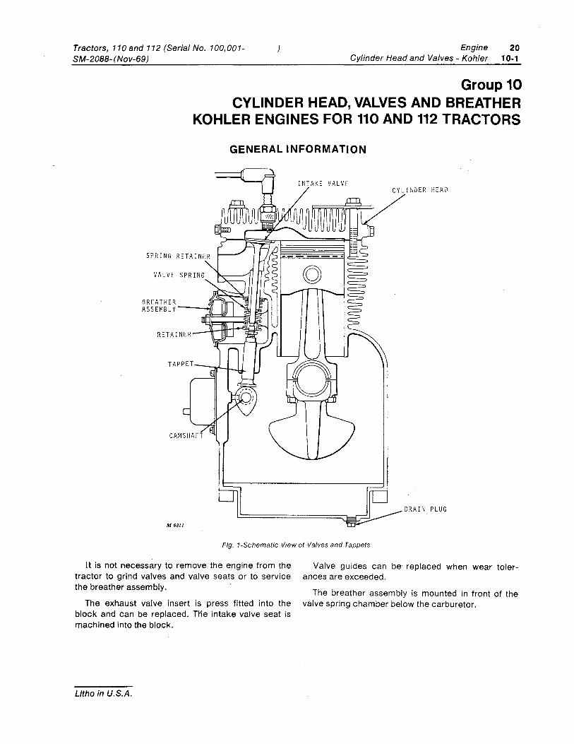
Fig. 1-Schematic View of Valves and Tappets
It is not necessary to remove the engine from the tractor to grind valves and valve seats or to service the breather assembly.
The exhaust valve insert is press fitted into the block and can be replaced. Hie intake valve seat is machined into the block.
Litho in U.S.A.
Valve guides can be' replaced when wear toler-ances are exceeded.
The breather assembly is mounted in front of the valve spring chamber below the carburetor.
20 10-2
Engine Cylinder Head and Valves - Kohler
Tractors, 110and 112 (Serial No. 100,001- ) SM-2088-(Nov-69)
VALVE ANALYSIS
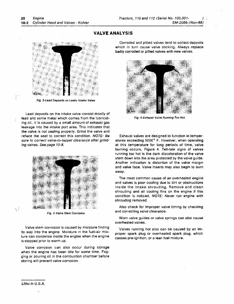
Fig. 2-Lead Deposits on Leaky Intake Valve
Lead deposits on the intake valve consist mostly of lead and some metal which comes from the lubricat-ing oil. It is caused by a small amount of exhaust gas leakage into the intake port area. This indicates that the valve is not sealing properly. Grind the valve and reface the seat to correct this condition. NOTE: Be sure to correct valve-to-tappet clearance after grind-ing valves. See page 10-8.
Fig. 3-Valve Stem Corrosion
Valve stem corrosion is caused by moisture finding its way into the engine. Moisture in the fuel-air mix-ture can condense inside the engine when the engine is stopped prior to warm up.
Valve corrosion can also occur during storage when the engine has been idle for some time. Fog-ging or pouring oil in the combustion chamber before storing will prevent valve corrosion.
Litho in U.S.A.
Corroded and pitted valves tend to collect deposits which in turn cause valve sticking. Always replace badly corroded or pitted valves with new valves.
Fig. 4-Exhaust Valve Running Too Hot
Exhaust valves are designed to function in temper-atures exceeding 5000° F. However, when operating at this temperature for long periods of time, valve burning occurs, Figure 4. Tell-tale signs of valves running too hot is the dark discoloration of the valve stem down into the area protected by the valve guide. Another indication is distortion of the valve margin and valve face. Valve inserts may also begin to burn away.
The most common cause of an overheated engine and valves is poor cooling due to dirt or obstructions inside the intake shrouding. Remove and clean shrouding and all cooling fins on the engine if this condition is noticed. NOTE: Never run engine with shrouding removed.
Also check for improper valve timing by checking and correcting valve clearance.
Worn valve guides or valve springs can also cause overheated valves.
Valves running hot also can be caused by an im-proper spark plug or overheated spark plug, which causes pre-ignition, or a lean fuel mixture.
Tractors, 110and 112 (Serial No. 100,001-SM-2088- (Nov-69)
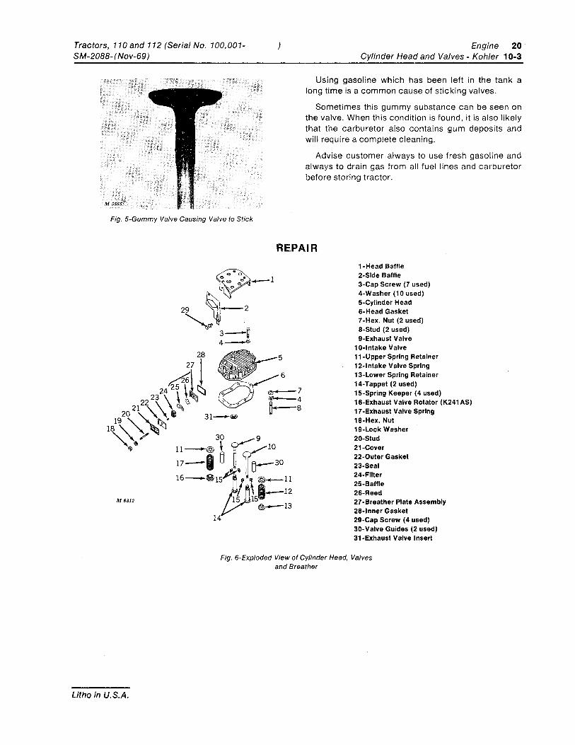
Fig. 5-Gummy Valve Causing Valve to Stick
) Engine 20 Cylinder Head and Valves - Kohler 10-3
Using gasoline which has been left in the tank a long time is a common cause of sticking valves.
Sometimes this gummy substance can be seen on the valve. When this condition is found, it is also likely that the carburetor also contains Qum deposits and will require a complete cleaning.
Advise customer always to use fresh gasoline and always to drain gas from all fuel lines and carburetor before storing tractor.
REPAIR l-Head Baffle 2-Side Baffle 3-Cap Screw (7 used) 4-Washer (10 used) 5-Cylinder Head 6-Head Gasket 7-Hex. Nut (2 used) 8-Stud (2 used) 9-Exhaust Valve
10-lntake Valve ll-Upper Spring Retainer 12-lntake Valve Spring 13-Lower Spring Retainer 14-Tappet (2 used) 15-Spring Keeper (4 used) 16-Exhaust Valve Rotator (K241AS) 17-Exhaust Valve Spring l8-Hex. Nut 19-Lock Washer 20-Stud 21-Cover 22-0uter Gasket 23-Seal 24-Filter 25-Baffle 26-Reed 27-Breather Plate Assembly 28-lnner Gasket 29-Cap Screw (4 used) 30-Valve Guides (2 used) 3l-Exhaust Valve Insert
Fig. 6-Exploded View of Cylinder Head, Valves and Breather
Litho in U.S.A.
20 Engine Tractors, 110 and 112 (Serial No. 100,001- ) 10-4 Cylinder Head and Valves - Kohler SM-20BB-(Nov-69)
REPAI R-Continued
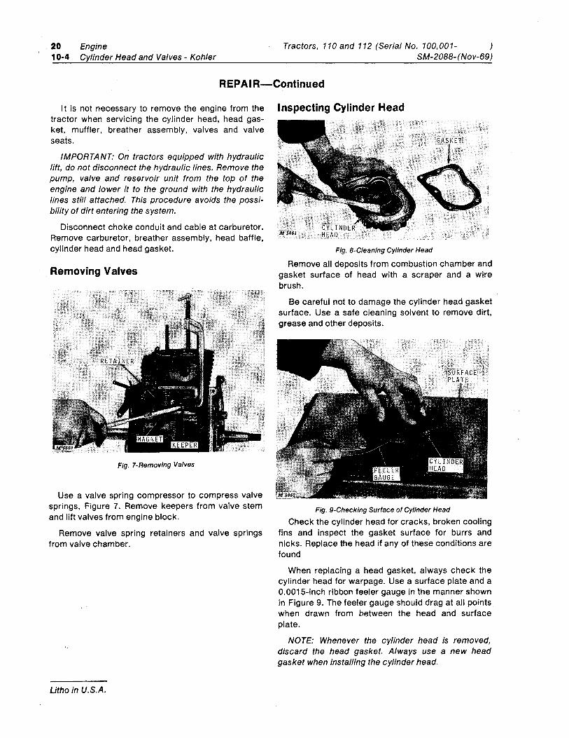
It is not necessary to remove the engine from the Inspecting Cylinder Head tractor when servicing the cylinder head, head gas-ket, muffler, breather assembly, valves and valve seats.
IMPORTANT: On tractors equipped with hydraulic lift, do not disconnect the hydraulic lines. Remove the pump, valve and reservoir unit from the top of the engine and lower it to the ground with the hydraulic fines still attached. This procedure avoids the possi-bility of dirt entering the system.
Disconnect choke conduit and cable at carburetor. Remove carburetor, breather assembly, head baffle. cylinder head and head gasket.
Removing Valves
Fig. 7-Removing Valves
Use a valve spring compressor to compress valve springs, Figure 7. Remove keepers from valve stem and lift valves from engine block.
Remove valve spring retainers and valve springs from valve chamber.
Litho in U.S.A.
Fig. 8-Cleaning Cylinder Head
Remove all deposits from combustion chamber and gasket surface of head with a scraper and a wire brush.
Be careful not to damage the cylinder head gasket surface. Use a safe cleaning solvent to remove dirt, grease and other deposits.
Fig. 9-Checking Surface of Cylinder Head Check the cylinder head for cracks, broken cooling
fins and inspect the gasket surface for burrs and nicks. Replace the head if any of these conditions are found
When replacing a head gasket, always check the cylinder head for warpage. Use a surface plate and a O.001S-inch ribbon feeler gauge in the manner shown in Figure 9. The feeler gauge should drag at all points when drawn from between the head and surface plate.
NOTE: Whenever the cylinder head is removed, discard the head gasket. Always use a new head gasket when installing the cylinder head.
Tractors, 110 and 112 (Serial No. 100,001-SM-2088- (Nov-69)
Inspecting Breather
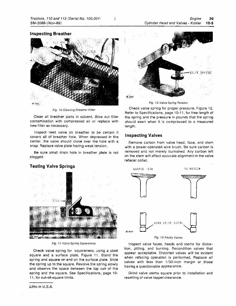
Fig. 10-Cleaning Breather Filter
)
Clean all breather parts in solvent. Blowout filter contamination with compressed air or replace with new filter as necessary.
Inspect reed valve on breather to be certain it covers all of breather hole. When depressed in the center, the valve should close over the hole with a snap. Replace valve plate having weak tension.
Be sure small drain hole in breather plate is not clogged.
Testing Valve Springs
Fig. 11-Valve Spring Squareness
Check valve spring for squareness, using a steel square and a surface plate, Figure 11. Stand' the spring and square on end on the surface plate. Slide the spring up to the square. Revolve the spring slowly and observe the space between the top coil of the spring and the square. See Specifications, page 10-11, for out-of-square limits.
Litho in U.S.A.
M 5665,'
Engine Cylinder Head and Valves - Kohler
Fig. 12-Valve Spring Tension
20 10-5
Check valve spring for proper pressure, Figure 12. Refer to Specifications, page 10-11 , for free length of the spring and the pressure in pounds that the spring should exert when it is compressed to a measured length.
Inspecting Valves Remove carbon from valve head, face, and stem
with a power-operated wire brush. Be sure carbon is removed and not merely burnished. Any carbon left on the stem will affect accurate alignment in the valve refacer collet.
WARPED HEAD NO MARGIN
M 8505
Fig. 13-Faulty Valves
Inspect valve faces, heads and stems for distor-tion,. pitting, and burning. Recondition valves that appear acceptable. Distorted valves will be evident when refacing operation is performed. Replace all valves with less than 1/32-inch margin or those having a questionable appearance.
Grind valve stems square prior to installation and resetting of valve tappet clearance.
20 10-6
Engine Cylinder Head and Valves - Kohler
Reconditioning or Replacing Valves
Valve Guides
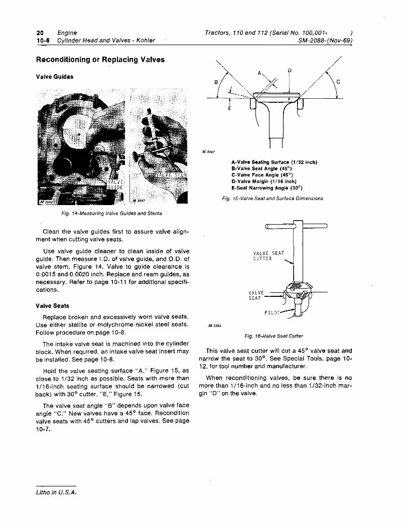
Fig. 14-Measuring Valve Guides and Stems
Clean the valve guides first to assure valve align-ment when cutting valve seats.
Use valve guide cleaner to clean inside of valve guide. Then measure 1.0. of valve guide, and 0.0. of valve stem, Figure 14. Valve to guide clearance is 0.0015 and 0.0020 inch. Replace and ream guides, as necessary. Refer to page 1 0-11 for additional specifi-cations.
Valve Seats
Replace broken and excessively worn valve seats. Use either stellite or molychrome nickel steel seats. Follow procedure on page 10-8.
The intake valve seat is machined into the cylinder block. When required, an intake valve seat insert may be installed. See page 10-8.
Hold the valve seating surface "A," Figure 15, as close to 1/32 inch as possible. Seats with more than 1/16-inch seating surface should be narrowed (cut back) with 30° cutter, "E," Figure 15.
The valve seat angle "8" depends upon valve face angle "C." New valves have a 45° face. Recondition valve seats with 45° cutters and lap valves. See page 10-7.
Litho in U.S.A.
Tractors, 110 and 112 (Serial No. 100,001- )
M 5567
M 5568
SM-2088- (Nov-69)
A-Valve Seating Surface (1/32 inch) B-Valve Seat Angle (45°) C-Valve Face Angle (45°) D-Valve Margin (1/16 inch) E-Seat Narrowing Angle (30°)
Fig. 15-Valve Seat and Surface Dimensions
VALVE SEAT CUTTER
SEAT
PILOT
Fig. 16-Valve Seat Cutter
/ /
This valve seat cutter will cut a 45° valve seat and narrow the seat to 30°. See Special Tools, page 10-12, for tool number and manufacturer.-
When reconditioning valves, be sure there is no more than 1 /16-inch and no less than 1/32-inch mar-gin "0" on the valve.
Tractors, 110 and 112 (Serial No. 100,001-SM-2088-(Nov-69)
RIGHT
WRONG WRONG M 5569
Fig. 17-Valve and Seat Relationship
)
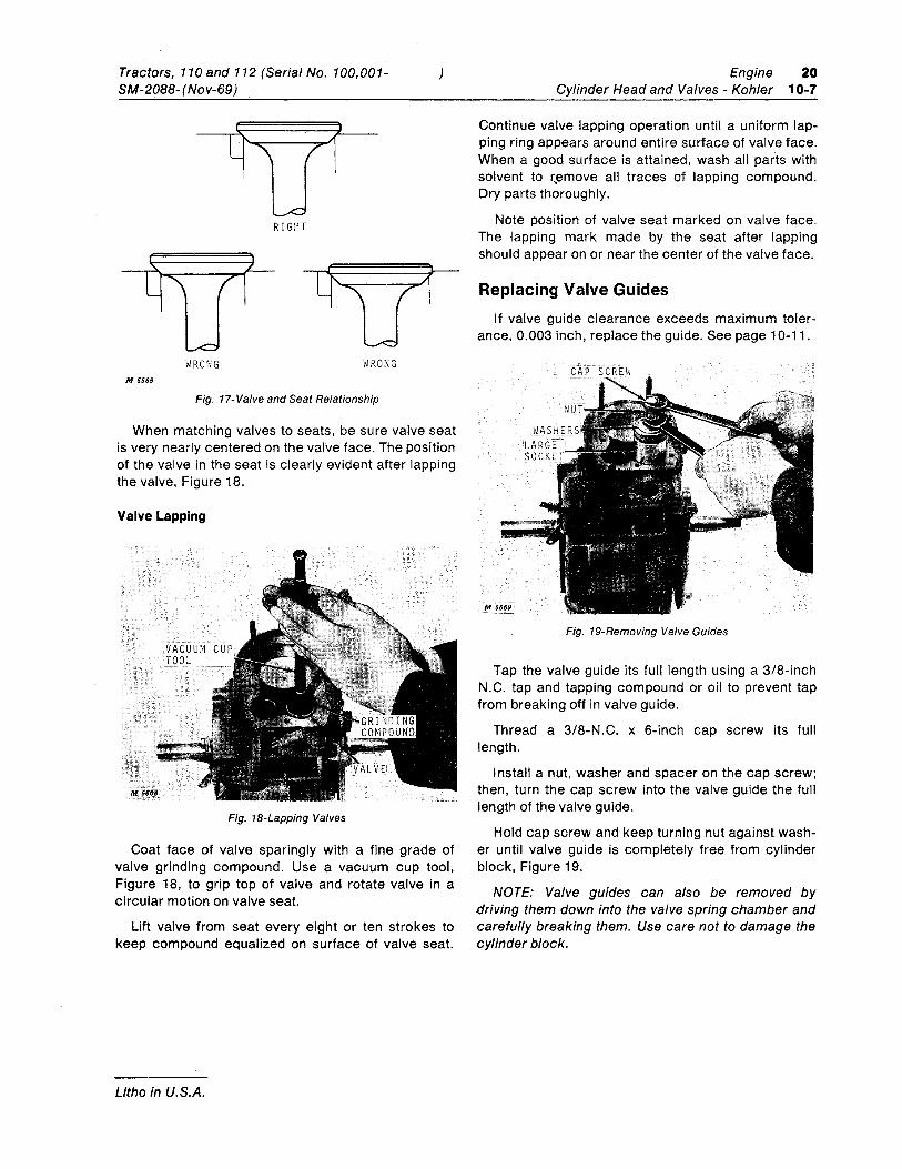
When matching valves to seats, be sure valve seat is very nearly centered on the valve face. The position of the valve in the seat is clearly evident after lapping the valve, Figure 18.
Valve Lapping
(M 56,6.8
VACUUM TOOL
Fig. 18-Lapping Valves
Coat face of valve sparingly with a fine grade of valve grinding compound. Use a vacuum cup tool, Figure 18, to grip top of valve and rotate valve in a circular motion on valve seat.
Lift valve from seat every eight or ten strokes to keep compound equalized on surface of valve seat.
Litho in U.S.A.
Engine 20 Cylinder Head and Valves - Kohler 10-7
Continue valve lapping operation until a uniform lap-ping ring appears around entire surface of valve face. When a good surface is attained, wash all par'ts with solvent to r,emove all traces of lapping compound. Dry parts thoroughly.
Note position of valve seat marked on valve face. The lapping mark made by the seat after lapping should appear on or near the center of the valve face.
Replacing Valve Guides If valve guide clearance exceeds maximum toler-
ance, 0.003 inch, replace the guide. See page 10-11.
SCREW
Fig. 19-Removing Valve Guides
Tap the valve guide its full length using a 3/8-inch N.C. tap and tapping compound or oil to prevent tap from breaking off in valve guide.
Thread a 3/8-N.C. x 6-inch cap screw its full length.
Install a nut, washer and spacer on the cap screw; then, turn the cap screw into the valve guide the full length of the valve guide.
Hold cap screw and keep turning nut against wash-er until valve guide is completely free from cylinder block, Figure 19.
NOTE: Valve guides can also be removed by driving them down into the valve spring chamber and carefully breaking them. Use care not to damage the cylinder block.
20 Engine 10-8 Cylinder Head and Valves - Kohler
Replacing Valve Guides-Continued
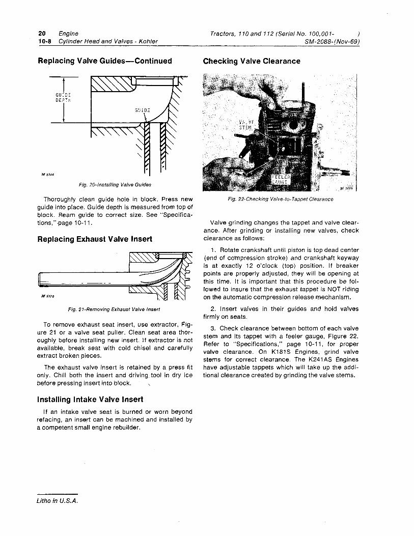
M 8506
1 GUIDE DEPTH
Fig. 20-lnstalling Valve Guides
Thoroughly clean guide hole in block. Press new guide into place. Guide depth is measured from top of block. Ream guide to correct size. See "Specifica-tions," ·page 10-11.
Replacing Exhaust Valve Insert
M 5570
Fig. 21-Removing Exhaust Valve Insert
To remove exhaust seat insert, use extractor, Fig-ure 21 or a valve seat puller. Clean seat area thor-oughly before installing new insert. If extractor is not available, break seat with cold chisel and carefully extract broken pieces.
The exhaust valve insert is retained by a press fit only. Chill both the insert and driving tool in dry ice before pressing insert into block.
I nstalling I ntake Valve Insert If an intake valve seat is burned or worn beyond
refacing, an insert can be machined and installed by a competent small engine rebuilder.
Litho in U.S.A.
Tractors, 110 and 112 (Serial No. 100,001- ) SM-2088-(Nov-69)
Checking Valve Clearance
Fig. 22-Checking Valve-to- Tappet Clearance
Valve grinding changes the tappet and valve clear-ance. After grinding or installing new valves, check clearance as follows:
1. Rotate crankshaft until piston is top dead center (end of compression stroke) and crankshaft keyway is at exactly 12 o'clock (top) position. If breaker points are properly adjusted, they will be opening at this time. It is important that this procedure be fol-lowed to insure that the exhaust tappet is NOT riding on the automatic compression release mechanism.
2. Insert valves in their guides and hold valves firmly on seats.
3. Check clearance between bottom of each valve stem and its tappet with a feeler gauge, Figure 22. Refer to "Specifications," page 10-11, for proper valve clearance. On K181 S Engines, grind valve stems for correct clearance. The K241 AS Engines have adjustable tappets which will take up the addi-tional clearance created by grinding the valve stems.
Tractors, 110and 112 (Serial No. 100,001-SM-2088-(Nov-69)
Engine Cylinder Head and Valves - Kohler
20 10-9
INSTALLATION
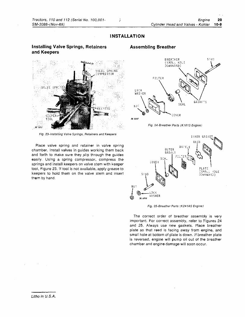
Installing Valve Springs, Retainers and Keepers
Fig. 23-lnstalling Valve Springs, Retainers and Keepers
Place valve spring and retainer in valve spring chamber. I nstall valves in guides working them back and forth to make sure they .slip through the guides easily. Using a spring compressor, compress the springs and install keepers on valve stem with keeper tool, Figure 23. If tool is not available, apply grease to keepers to hold them on the valve stem and insert them by hand.
Litho in U.S.A.
Assembling Breather
BREATHER STUD (SMALL HOLE V DOWNWARD)
M 8507
Fig. 24-Breather Parts (K181S Engine)
INNER GASKET
OUTER I ,&-0 ( GASKET t
SEAL COVER
PLATE (SMALL HOLE
WASHER \::i M 8508
Fig. 25-Breather Parts (K241AS Engine)
The correct order of breather assembly is very important. For correct assembly, refer to Figures 24 and 25. Always use new gaskets. Place breather plate so that reed is facing away from engine, and small hole at bottom of plate is down. If breather plate is reversed, engine will pump oil out of the breather chamber and engine damage will soon occur.
20 Engine 10-10 Cylinder Head and Valves - Kohler
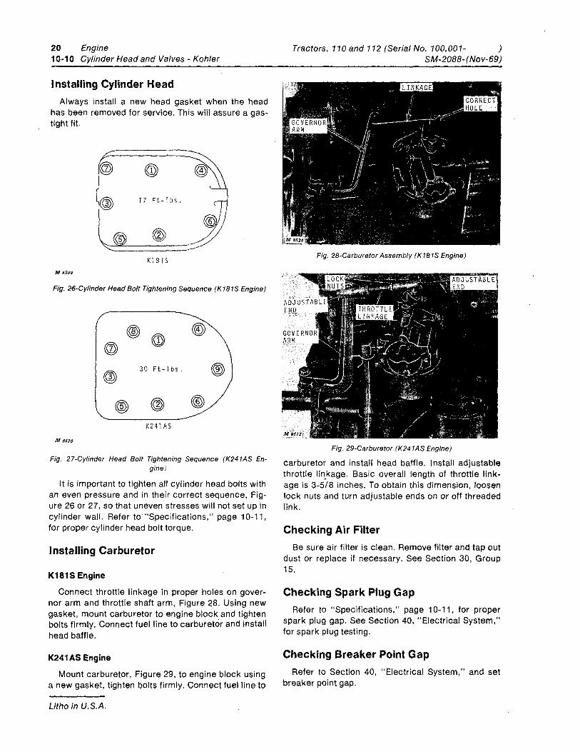
Installing Cylinder Head Always install a new head gasket when the head
has been removed for service. This will assure a gas-tight fit.
17 Ft-1bs.
K181 S M 8509
Fig. 26-Cylinder Head Bolt Tightening Sequence (K181S Engine)
30 Ft-lbs.
K241AS
M 8510
Fig. 27-Cylinder Head Bolt Tightening Sequence (K241AS En-gine)
It is important to tighten all cylinder head bolts with an even pressure and in their correct sequence, Fig-ure 26 or 27, so that uneven stresses will not set up in cylinder wall. Refer to "Specifications," page 1 0-11, for proper cylinder head bolt torque.
Installing Carburetor
K181S Engine
Connect throttle linkage in proper holes on gover-nor arm and throttle shaft arm, Figure 28. Using new gasket, mount carburetor to engine block and tighten bolts firmly. Connect fuel line to carburetor and install head baffle.
K241AS Engine
Mount carburetor, Figure 29, to engine block using a new gasket, tighten bolt's firmly. Connect fuel line to
Litho in U.S.A.
Tractors, 110 and 112 (Serial No. 100,001- ) SM-2088- (Nov-69)
Fig. 28-Carburetor Assembly (K181S Engine)
Fig. 29-Carburetor (K241AS Engine)
carburetor and install head baffle. Install adjustable throttle lin.kage. Basic overall length of throttle link-age is 3-5/8 inches. To obtain this dimension, loosen lock nuts and turn adjustable ends on or off threaded link.
Checking Air Filter Be sure air filter is clean. Remove filter and tap out
dust or replace if necessary. See Section 30, Group 15.
Checking Spark Plug Gap Refer to "Specifications," page 1 0-11, for proper
spark plug gap. See Section 40, "Electrical System," for spark plug testing.
Checking Breaker Point Gap Refer to Section 40, "Electrical System," and set
breaker point gap.
Tractors, 110 and 112 (Serial No. 100,001-SM-2088- (Nov-69)
)
SPECIFICATIONS
Engine Cylinder Head and Valves - Kohler
20 10-11
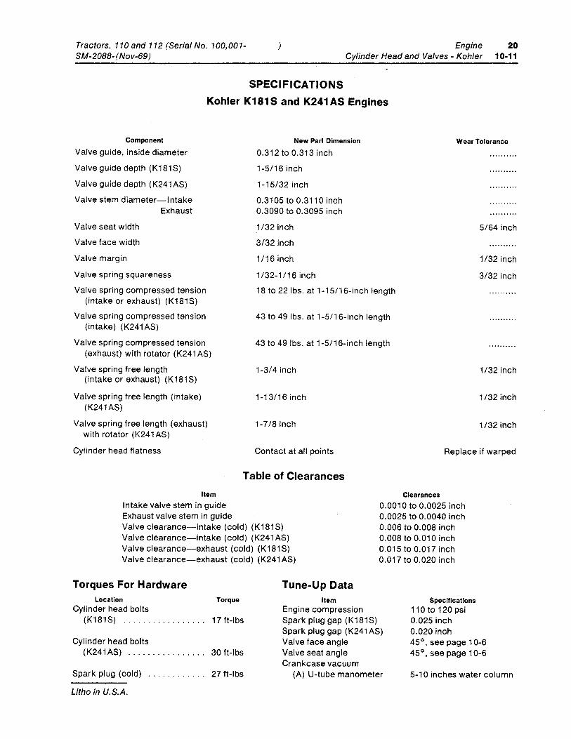
Kohler K181S and K241 AS Engines
Component
Valve guide, inside diameter
Valve guide depth (K181S)
Valve guide depth (K241 AS)
Valve stem diameter-Intake
Valve seat width
Valve face width
Valve margin
Exhaust
Valve spring squareness
Valve spring compressed tension (intake or exhaust) (K181S)
Valve spring compressed tension (intake) (K241AS)
Valve spring compressed tension (exhaust) with rotator (K241 AS)
Valve spring free length (intake or exhaust) (K181S)
Valve spring free length (intake) (K241AS)
Valve spring free length (exhaust) with rotator (K241 AS)
Cylinder head flatness
New Part Dimension
0.312 to 0.313 inch
1-5/16 inch
1-15/32 inch
0.3105 to 0.3110 inch 0.3090 to 0.3095 inch
1/32 inch
3/32 inch
1/16inch
1/32-1/16 inch
18 to 22 Ibs. at 1-15/16-inch length
43 to 49 Ibs. at 1-5/16-inch length
43 to 49 Ibs. at 1-5/16-inch length
1-3/4 inch
1-13/16 inch
1-7/8 inch
Contact at all points
Wear Tolerance
5/64 inch
1/32 inch
3/32 inch
1/32 inch
1/32 inch
1/32 inch
Replace if warped
Table of Clearances Item
Intake valve stem in guide Exhaust valve stem in guide Valve clearance-intake (cold) (K181S) Valve clearance-intake (cold) (K241 AS) Valve clearance-exhaust (cold) (K181S) Valve clearance-exhaust (cold) (K241 AS)
Clearances 0.0010 to 0.0025 inch 0.0025 to 0.0040 inch 0.006 to 0.008 inch 0.008 to 0.010 inch 0.015 to 0.017 inch 0.017 to 0.020 inch
Torques For Hardware Location Torque
Cylinder head bolts (K181S) ................. 17 ft-Ibs
Cylinder head bolts (K241AS) ................ 30 ft-Ibs
Spark plug (cold)
Litho in U.S.A.
27 ft-Ibs
Tune-Up Data Item
Engine compression Spark plug gap (K181S) Spark plug gap (K241AS) Valve face angle Valve seat angle Crankcase vacuum
(A) U-tube manometer
Specifications 110 to 120 psi 0.025 inch 0.020 inch 45 0
, see page 1 0-6 45 0
, see page 10-6
5-10 inches water column
20 Engine Tractors, 110 and 112 (Serial No. 100,001- ) 10-12 Cylinder Head and Valves - Kohler SM-2088-(Nov-69)
Name
Extractor
Valve Spring Tester
Adjustable Reamers
Valve Grinding Com-pound
Valve Keeper Re-placer
Valve Lifter
U-Tube Manometer
Valve Seat Cutter Kit for Kohler Engines
Litho in U.S.A.
SPECIAL TOOLS Part No.
K.O. LEE R95
STURTEDANT Model SPT
QUICK SET 43
8-K 1896
KD608
SNAP ON CF19
DWYER Model 1211-24
NEWAY No. 102S Kit, NEWAY Sales Inc., Corunna, Michigan
Use
To remove exhaust valve seat insert.
To check valve spring pressure.
Ream valve guides after installation.
To lap valve seat and valve face.
To install keepers on valve stem.
To compress valve springs
Check crankcase vacuum.
Recondition valve seat.
Tractors, 110 and 112 (Serial No. 100,001-SM-2088-(Nov-69)
) Engine 20 Piston, Crankshaft and Flywheel- Kohler 15-1
Group 15 PISTON, CRANKSHAFT, MAIN BEARINGS AND FLYWHEEL
KOHLER ENGINES FOR 110 AND 112 TRACTORS
GENERAL INFORMATION
M 8513
CONNECTING ROD
MAIN BEARING
\ CRANKSHAFT
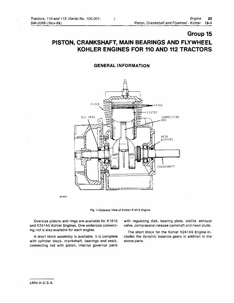
Fig. 1-Cutaway View of Kohler K181S Engine
Oversize pistons and rings are available for K181S and K241 AS Kohler Engines. One undersize connect-ing rod is also available for each engine.
A short block assembly is available. It is complete with cylinder block, crankshaft, bearings and seals, connecting rod with piston, internal governor parts
Litho in U.S.A.
with regulating disk, bearing plate, stellite exhaust valve, compression release camshaft and head studs.
The short block for the Kohler K241 AS Engine in-cludes the dynamic balance gears in addition to the above parts.
20 15·2
Engine Tractors, 110 and 112 (Serial No. 100,001- ) Piston, Crankshaft and Flywheel - Kohler SM-2088-(Nov-69)
32 I 24
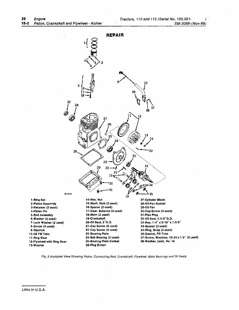
1-Rlng Set 2-Piston Assembly 3-Retainer (2 used) 4-Piston Pin
Assembly 6-Washer (2 used) 7-Lock Washer (2 used) S-Screw (2 used) 9-0ipstick
10-011 Fill Tube 11-Ring Gear
M8514
12-Flywheel with Ring Gear 13-Washer
REPAIR
14-Hex. Nut 15-Shaft, Stub (2 used) 16-Spacer (2 used) 17-Gear, Balance (2 used) 1S-Shim (2 used) 19-Crankshaft 20-011 Seal, 2"0.0. 21-Cap Screw (S used) 22-Cap Screw (6 used) 23-Bearing Plate 24-Ball Bearing (2 used) 25-Bearing Plate Gasket 26-Plug Button
27 -Cylinder Block 2S-011 Pan Gasket 29-011 Pan 30-Cap Screw (4 used) 31-Pipe Plug 32-011 Seal, 2-3/S"0.0. 33-Key, 1/4" x 3/16" x 1-3/S" 34-Spacer (2 used) 35-Ring, Snap (2 used) 36-Gasket, Fill Tube 37 -Screw, Machine, 10-24 x 1/2" (3 used) 3S-Washer, Lock, No. 10
Fig. 2-Exploded View Showing Piston, Connecting Rod, Crankshaft, Flywheel, Main Bearings and Oil Seals
Litho in U.S.A.
Tractors, 110 and 112 (Serial No. 100,001-SM-2088- (Nov-69)
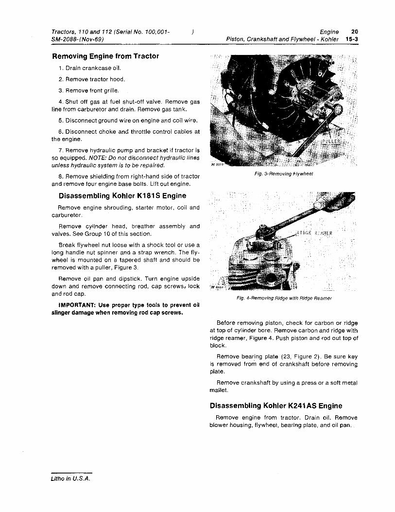
Removing Engine from Tractor 1. Drain crankcase oil.
2. Remove tractor hood.
3. Remove front grille.
4. Shut off gas at fuel shut-off valve. Remove gas line from carburetor and drain. Remove gas tank.
5. Disconnect ground wire on engine and coil wire.
6. Disconnect choke and throttle control cables at the engine.
7. Remove hydraulic pump and bracket if tractor is so equipped. NOTE: Do not disconnect hydraulic lines unless hydraulic system is to be repaired.
8. Remove shielding from right-hand side of tractor and remove four engine base bolts. Lift out engine.
Disassembling Kohler K181 S Engine Remove engine shrouding, starter motor, coil and
carburetor.
Remove cylinder head, breather assembly and valves. See Group 10 of this section.
Break flywheel nut loose with a shock tool or use a long handle nut spinner and a strap wrench. The fly-wheel is mounted on a tapered shaft and should be removed with a puller, Figure 3.
Remove oil pan and dipstick. Turn engine upside
Engine 20 Piston, Crankshaft and Flywheel - Kohler 15-3
Fig. 3-Removing Flywheel
down and remove connecting rod, cap screws, lock ,M
and rod cap.
IMPORTANT: Use proper type tools to prevent oil slinger damage when removing rod cap screws.
Litho in U.S.A.
Fig. 4-Removing Ridge with Ridge Reamer
Before removing piston, check for carbon or ridge at top of cylinder bore. Remove carbon and ridge with ridge reamer, Figure 4. Push piston and rod out top of block.
Remove bearing plate (23, Figure 2). Be sure key is removed from end of crankshaft before removing plate.
Remove crankshaft by using a press or a soft metal mallet.
Disassembling Kohler K241 AS Engine Remove engine from tractor. Drain oil. Remove
blower housing, flywheel, bearing plate, and oil pan.
20 Engine 15-4 Piston, Crankshaft and Flywheel - Kohler
Disassembling Kohler K241AS Engine-Continued
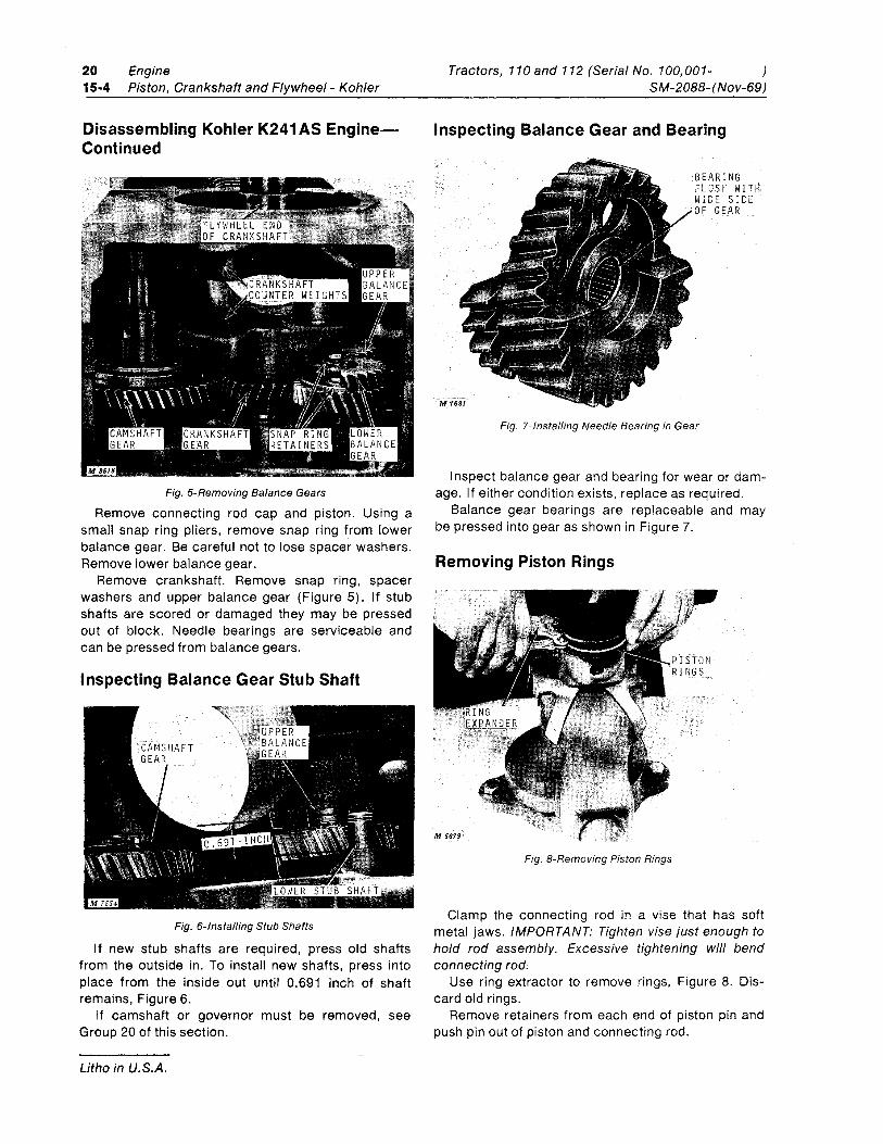
Fig. 5-Removing Balance Gears
Remove connecting rod cap and piston. Using a small snap ring pliers, remove snap ring from lower balance gear. Be careful not to lose spacer washers. Remove lower balance gear.
Remove crankshaft. Remove snap ring, spacer washers and upper balance gear (Figure 5). If stub shafts are scored or damaged they may be pressed out of block. Needle bearings are serviceable and can be pressed from balance gears.
Inspecting Balance Gear Stub Shaft
Fig. 6-lnstalling Stub Shafts
If new stub shafts are required, press old shafts from the outside in. To install new shafts, press into place from the inside out until 0.691 inch of shaft remains, Figure 6.
If camshaft or governor must be removed, see Group 20 of this section.
Litho in U.S.A.
Tractors, 110 and 112 (Serial No. 100,001- ) SM-20BB-(Nov-69)
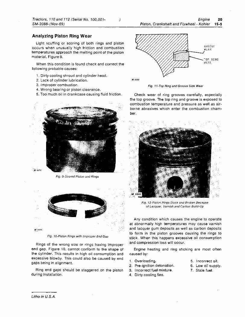
Inspecting Balance Gear and Bearing
BEARING FLUSH WITH WIDE SIDE OF GEAR
Fig. 7-lnstalling Needle Bearing in Gear
I nspect balance gear and bearing for wear or dam-age. If either condition exists, replace as required.
Balance gear bearings are replaceable and may be pressed into gear as shown in Figure 7.
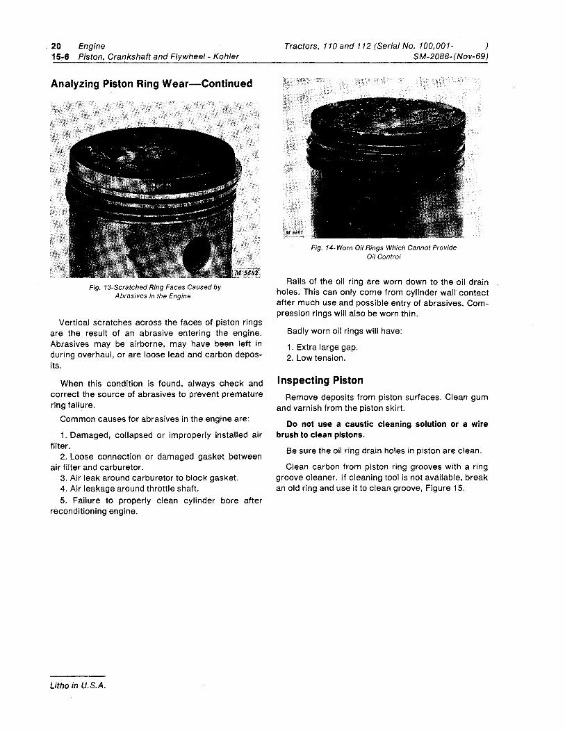
Removing Piston Rings
Fig. 8-Removing Piston Rings
Clamp the connecting rod in a vise that has soft metal jaws. IMPORTANT: Tighten vise just enough to hold rod assembly. Excessive tightening will bend connecting rod:
Use ring extractor to remove rings, Figure 8. Dis-card old rings.
Remove retainers from each end of piston pin and push pin out of piston and connecting rod.
Tractors, 110 and 112 (Serial No. 100,001-SM-2088-(Nov-69)
Analyzing Piston Ring Wear
)
Light scuffing or scoring of both rings and piston occurs when unusually high friction and combustion temperatures approach the melting pOint of the piston material, Figure 9.
When this condition is found check and correct the following probable causes:
1. Dirty cooling shroud and cylinder head. 2. Lack of cylinder lubrication. 3. Improper combustion. 4. Wrong bearing or piston clearance. 5. Too much oil in crankcase causing fluid friction.
M 5578
Fig. 9-Scored Piston and Rings
M 5579
Fig. 10-Piston Rings with Improper End Gap
Rings of the wrong size or rings having improper end gap, Figure 10, cannot conform to tl:le shape of the cylinder. This results in high oil consumption and excessive blowby. This could also be caused by end gaps being in alignment.
Ring end gaps should be staggered on the piston during installation.
Litho in U.S.A.
Engine 20 Piston, Crankshaft and Flywheel - Kohler 15-5
GROOVE ___ /WEAR
TOP RING WEAR
M 5580
Fig. 11-Top Ring and Groove Side Wear
Check wear of ring grooves carefully, especially the top groove. The top ring and groove is exposed to combustion temperature and pressure as well as air-borne abrasives which enter the combustion cham-ber.
Fig. 12-Piston Rings Stuck and Broken Because of Lacquer, Varnish and Carbon Build-Up
Any condition which causes the engine to operate at abnormally high temperatures may cause varnish and lacquer gum deposits as well as carbon deposits to form in the piston grooves causing the rings to stick. When this happens excessive oil consumption and compression loss will occur.
Engine heating and ring sticking are most often caused by:
1. Overloading. 5. I ncorrect oil. 2. Pre-ignition detonation. 6. Low oil supply. 3. Incorrect fuel mixture. 7. Stale fuel. 4. Dirty cooling fins.
20 Engine 15-6 Piston, Crankshaft and Flywheel- Kohler
Analyzing Piston Ring Wear-Continued
Fig. 13-Scratched Ring Faces Caused by Abrasives in the Engine
Vertical scratches across the faces of piston rings are the result of an abrasive entering the engine. Abrasives may be airborne, may have been left in during overhaul, or are loose lead and carbon depos-its.
When this condition is found, always check and correct the source of abrasives to prevent premature ring failure.
Common causes for abrasives in the engine are:
1. Damaged, collapsed or improperly installed air filter.
2. Loose connection or damaged gasket between air filter and carburetor.
3. Air leak around carburetor to block gasket. 4. Air leakage around throttle shaft. 5. Failure to properly clean cylinder bore after
reconditioning engine.
Litho in U.S.A.
Tractors, 110and 112 (Serial No. 100,001- ) SM-2088- (Nov-69)
Fig. 14-Worn Oi/ Rings Which Cannot Provide Oi/Control
Rails of the oil ring are worn down to the oil drain holes. This can only come from cylinder wall contact after much use and possible entry of abrasives. Com-pression rings will also be worn thin.
Badly worn oil rings will have:
1. Extra large gap. 2. Low tension.
Inspecting Piston Remove deposits from piston surfaces. Clean gum
and varnish from the piston skirt.
Do not use a caustic cleaning solution or a wire brush to clean pistons.
Be sure the oil ring drain holes in piston are clean.
Clean carbon from piston ring grooves with a ring groove cleaner. If cleaning tool is not available, break an old ring and use it to clean groove, Figure 15.
Tractors, 110 and 112 (Serial No. 100,001-SM-2088- (Nov-69)
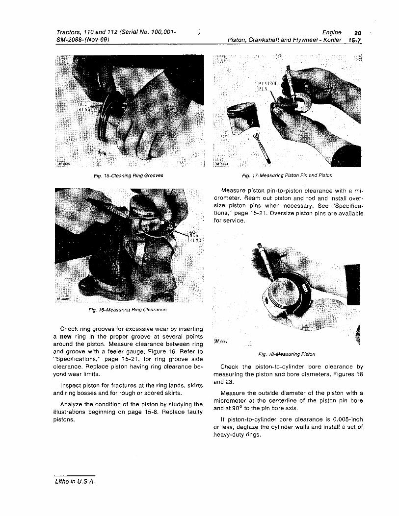
Fig. 15-Cleaning Ring Grooves
Fig. 16-Measuring Ring Clearance
)
NEW iRING
Check ring grooves for excessive wear by inserting a new ring in the proper groove at several points around the piston. Measure clearance between ring and groove with a feeler gauge, Figure 16. Refer to "Specifications," page 15-21, for ring groove side clearance. Replace piston having ring clearance be-yond wear limits.
I nspect piston for fractures at the ring lands, skirts and ring bosses and for rough or scored skirts.
Analyze the condition of the piston by studying the illustrations beginning on page 15-8. Replace faulty pistons.
Litho in U.S.A.
Engine 20 Piston, Crankshaft and Flywheel- Kohler 15-7
Fig. 17-Measuring Piston Pin and Piston
Measure piston pin-to-piston clearance with a mi-crometer. Ream out piston and rod and install over-size piston pins when necessary. See "Specifica-tions," page 15-21. Oversize piston pins are available for service.
M 5684
Fig. 18-Measuring Piston
Check the piston-to-cylinder bore clearance by measuring the piston and bore diameters, Figures 18 and 23.
Measure the outside diameter of the piston with a micrometer at the centerline of the piston pin bore and at 90° to the pin bore axis.
If piston-to-cylinder bore clearance is 0.005-inch or less, deglaze the cylinder walls and install a set of heavy-duty rings.
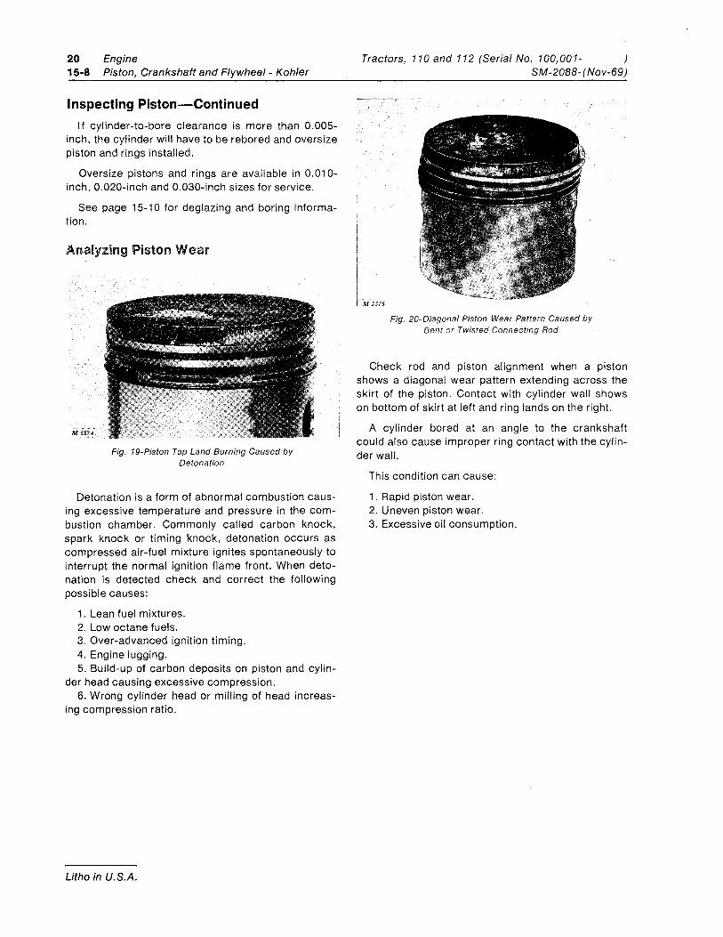
20 15-8
Engine Piston, Crankshaft and Flywheel - Kohler
I nspecting Piston-Continued If cylinder-to-bore clearance is more than 0.005-
inch, the cylinder will have to be rebored and oversize piston and rings installed.
Oversize pistons and rings are available in 0.010-inch, 0.020-inch and 0.030-inch sizes for service.
See page 15-10 for deglazing and boring informa-tion.
Analyzing Piston Wear
M 5574
Fig. 19-Piston Top Land Burning Caused by Detonation
Detonation is a form of abnormal combustion caus-ing excessive temperature and pressure in the com-bustion chamber. Commonly called carbon knock, spark knock or timing knock, detonation occurs as compressed air-fuel mixture ignites spontaneously to interrupt the normal ignition flame front. When deto-nation is detected check and correct the following possible causes:
1. Lean fuel mixtures. 2. Low octane fuels. 3. Over-advanced ignition timing. 4. Engine lugging. 5. Build-up of carbon deposits on piston and cylin-
der head causing excessive compression. 6. Wrong cylinder head or milling of head increas-
ing compression ratio.
Litho in U.S.A.
Tractors, 110 and 112 (Serial No. 100,001- ) SM-2088- (Nov-69)
M 5576
Fig. 20-Diagona/ Piston Wear Pattern Caused by Bent or Twisted Connecting Rod
Check rod and piston alignment when a piston shows a diagonal wear pattern extending across the skirt of the piston. Contact with cylinder wall shows on bottom of skirt at left and ring lands on the right.
A cylinder bored at an angle to the crankshaft could also cause improper ring contact with the cylin-der wall.
This condition can cause:
1. Rapid piston wear. 2. Uneven piston wear. 3. Excessive oil consumption.
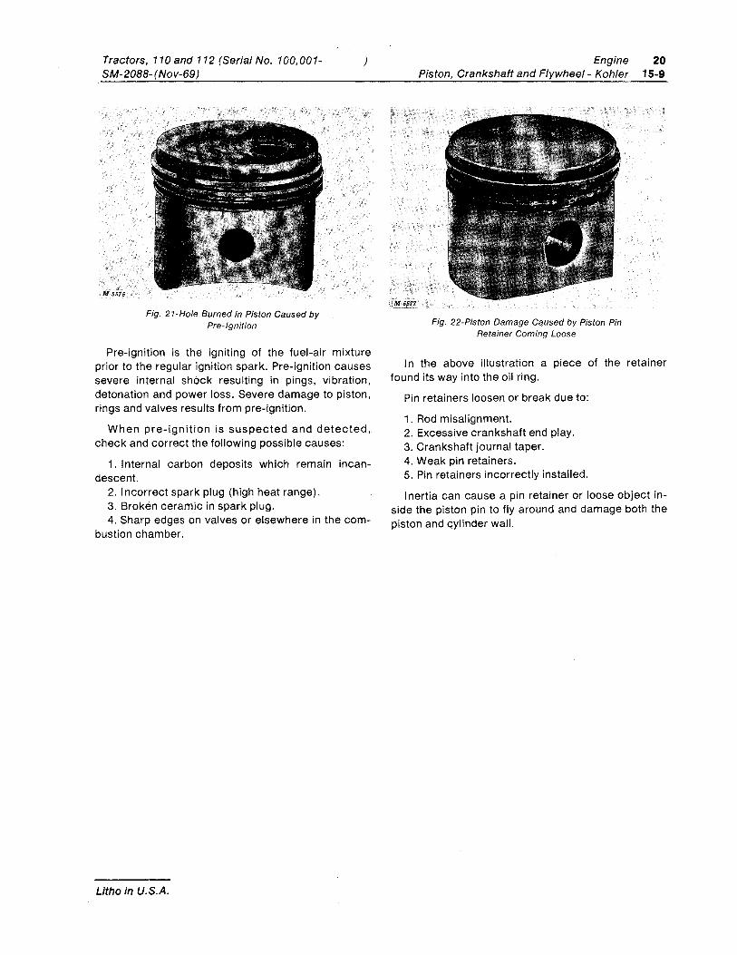
Tractors, 110and 112 (Serial No. 100,001-SM-2088-(Nov-69)
Fig. 21-Hole Burned in Piston Caused by Pre-Ignition
)
Pre-ignition is the igniting of the fuel-air mixture prior to the regular ignition spark. Pre-ignition causes severe internal shock resulting in pings, vibration, detonation and power loss. Severe damage to piston, rings and valves results from pre-ignition.
When pre-ignition is suspected and detected, check and correct the following possible causes:
1. I nternal carbon deposits which remain incan-descent.
2. I ncorrect spark plug (high heat range). 3. Broken ceramic in spark plug. 4. Sharp edges on valves or elsewhere in the com-
bustion chamber.
Litho in U.S.A.
Engine Piston, Crankshaft and Flywheel - Kohler
Fig. 22-Piston Damage Caused by Piston Pin Retainer Coming Loose
20 15-9
In the above illustration a piece of the retainer found its way into the oil ring.
Pin retainers loosen or break due to:
1. Rod misalignment. 2. Excessive crankshaft end play. 3. Crankshaft journal taper. 4. Weak pin retainers. 5. Pin retainers incorrectly installed.
Inertia can cause a pin retainer or loose object in-side the piston pin to fly around and damage both the piston and cylinder wall.
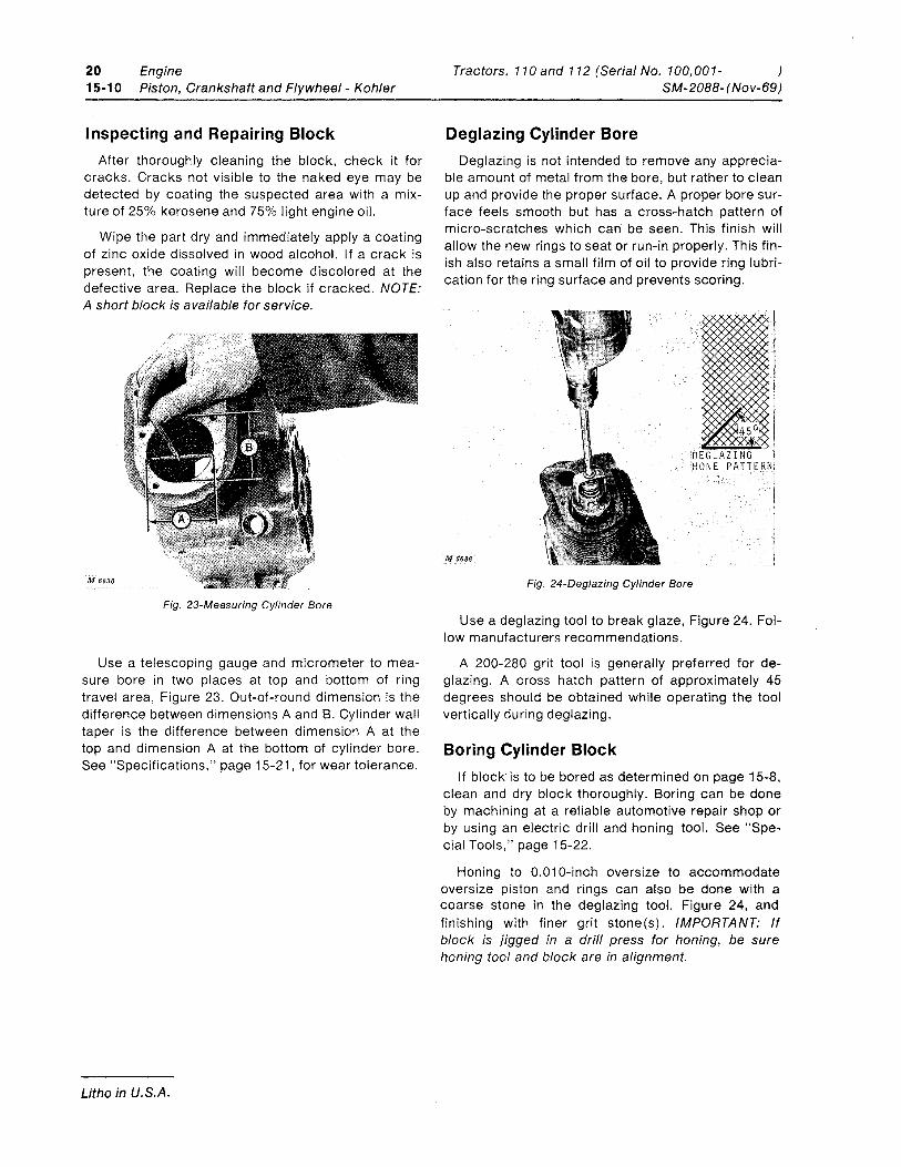
20 Engine 15-10 Piston, Crankshaft and Flywheel- Kohler
I nspecting and Repairing Block After thoroughly cleaning the block, check it for
cracks. Cracks not visible to the naked eye may be detected by coating the suspected area with a mix-ture of 25% kerosene and 75% light engine oil.
Wipe the part dry and immediately apply a coating of zinc oxide dissolved in wood alcohol. If a crack is present, the coating will become discolored at the defective area. Replace the block if cracked. NOTE: A short block is available for service.
M 6830
Fig. 23-Measuring Cylinder Bore
Use a telescoping gauge and micrometer to mea-sure bore in two places at top and bottom of ring travel area, Figure 23. Out-of-round dimension is the difference between dimensions A and B. Cylinder wall taper is the difference between dimension A at the top and dimension A at the bottom of cylinder bore. See "Specifications," page 15-21, for wear tolerance.
Litho in U.S.A.
Tractors, 110 and 112 (Serial No. 100,001- ) SM-2088-(Nov-69)
Deglazing Cylinder Bore Deglazing is not intended to remove any apprecia-
ble amount of metal from the bore, but rather to clean up and provide the proper surface. A proper bore sur-face feels smooth but has a cross-hatch pattern of micro-scratches which can be seen. This finish will allow the new rings to seat or run-in properly. This fin-ish also retains a small film of oil to provide ring lubri-cation for the ring surface and prevents scoring.
i M 5686 _I
Fig. 24-Deglazing Cylinder Bore
Use a deglazing tool to break glaze, Figure 24. Fol-low manufacturers recommendations.
A 200-280 grit tool is generally preferred for de-glazing. A cross hatch pattern of approximately 45 degrees should be obtained while operating the tool vertically during deglazing.
Boring Cylinder Block If block- is to be bored as determined on page 15-8,
clean and dry block thoroughly. Boring can be done by machining at a reliable automotive repair shop or by using an electric drill and honing tool. See "Spe-cial Tools," page 15-22.
Honing to 0.010-inch oversize to accommodate oversize piston and rings can also be done with a coarse stone in the deglazing tool, Figure 24, and finishing with finer grit stone(s). IMPORTANT: If block is jigged in a drill press for honing, be sure honing tool and block are in alignment.

Tractors, 110 and 112 (Serial No. 100,001-SM-2088- (Nov-69)
Inspecting Crankshaft
Fig. 25-Measuring Crankshaft Journal
)
Wipe crankshaft dry and check journal condition. Clean up threads on end of shaft if necessary. If crankshaft journal indicates wear, Figure 25, beyond specified limits or if journal is scored. take the crank-shaft to a competent machine shop to turn the journal down 0.010-inch. An undersize connecting rod and cap must then be installed. THIS IS IMPORTANT. Do not just replace a crankshaft having a bad journal. Turning down the journal and installing a new rod will likely be the least expensive method of repair.
Analyzing Connecting Rod and Cap Wear
Fig. 26-Crankshaft Connecting Rod and Cap
After cleaning and drying parts. check rod, Figure 2..6. and cap for signs of bending. cracking or unusual wear patterns.
Litho in U.S.A.
Engine 20 Piston, Crankshaft and Flywheel Kohler 15-11
CRANKSHAFT JOURNAL
M 8sSTi
Fig. 27-Scored and Galled Crankshaft Journal and Rod Cap Caused by Lack of Lubrication
Lack of lubrication or improper lubrication. Figure 27. can cause the connecting rod and cap to seize to the crankshaft and may even cause rod particles to become imbedded in the hardened steel crankshaft. When the rod and cap seize to the crankshaft. the connecting rod and piston may both break with shat-tering force causing other interior damage. When this happens inspect block carefully for cracks and break-age before rebuilding engine.
Crankshaft and connecting rod damage can result from:
1. Engine run Iowan oil or without oil. 2. Oil slinger broken off bearing cap. 3. Oil hole in connecting rod plugged. 4. Oil not changed regularly. 5. Bearing cap installed incorrectly.
Note especial!y the condition of the rod and cap bearing area. Evidence of score marks on these areas indicates impurities in the oil or engine run without oil. Replace rod showing scratch marks or deep scores in the bearing area. Bent rods can be straightened with a rod aligner. Be sure slinger on rod cap is intact - not cracked. bent or chipped. This is important. NOTE: New rods and caps are available only as a matched set for service. If either is damaged, both must be replaced.
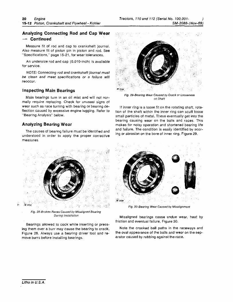
20 Engine 15-12 Piston, Crankshaft and Flywheel- Kohler
Analyzing Connecting Rod and Cap Wear - Continued
Measure fit of rod and cap to crankshaft journal. Also measure fit of piston pin in piston and rod. See "Specifications," page 15-21, for wear tolerances.
An undersize rod and cap (0.010-inch) is available for service.
NOTE: Connecting rod and crankshaft journal must be clean and meet specifications or a failure will reoccur.
Inspecting Main Bearings Main bearings turn in an oil mist and wi" not nor-
ma"y require replacing. Check for unusual signs of wear such as race turning with bearing or bearing de-flection caused by excessive engine lugging. Refer to "Bearing Analysis" below.
Analyzing Bearing Wear The causes of bearing failure must be identified and
understood in order to apply the proper corrective measures.
Fig. 28-Broken Races Caused by Misaligned Bearing During Installation
Bearings allowed to cock while inserting or press-ing them over a burr may cause the bearing to crack, Figure 28. Always use a bearing driver tool and re-move burrs before installing bearings.
Litho in U.S.A.
Tractors, 110 and 112 (Serial No. 100,001- ) SM-2088-(Nov-69)
;M 5585 .,'
Fig. 29-Bearing Wear Caused by Crack or Looseness on Shaft
If inner ring is a loose fit on the rotating shaft, rota-tion of the shaft within the inner ring can scuff loose sma" particles of metal. These eventually get into the bearing causing wear on the balls and races. This makes for noisy operation and shortened bearing life and failure. The condition is easily identified by scor-ing or abrasion on the bore of inner ring, Figure 29.
Fig. 3D-Bearing Wear Caused by Misalignment
Misaligned bearings cause undue wear, heat by friction and eventual failure, Figure 30.
Note the crooked ball paths in the raceways and the oval appearance of the balls and wear on the sep-arator caused by rubbing against the race.
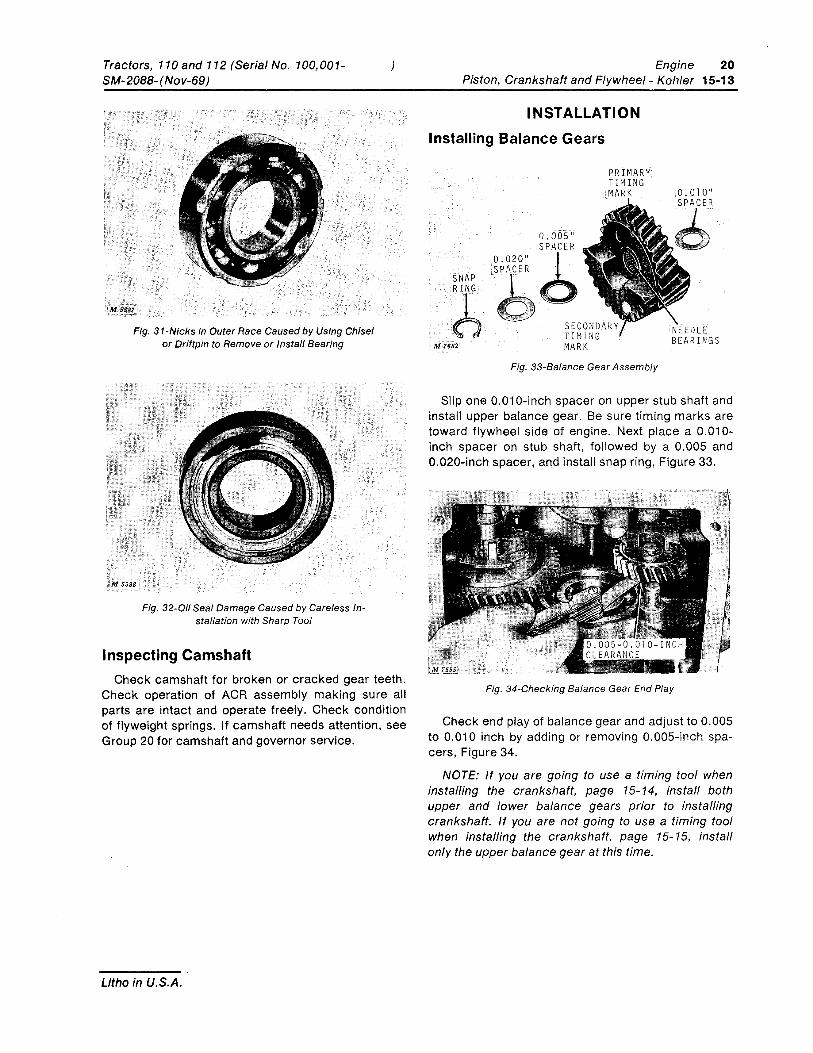
Tractors, 110 and 112 (Serial No. 100,001-SM-2088-(Nov-69)
Fig. 31-Nicks in Outer Race Caused by Using Chisel or Driftpin to Remove or Install Bearing
M $588
Fig. 32-0il Seal Damage Caused by Careless In-stallation with Sharp Tool
Inspecting Camshaft
}
Check camshaft for broken or cracked gear teeth. Check operation of ACR assembly making sure all parts are intact and operate freely. Check condition of flyweight springs. If camshaft needs attention, see Group 20 for camshaft and governor service.
Litho in U.S.A.
Engine 20 Piston, Crankshaft and Flywheel - Kohler 15-13
INSTALLATION Installing Balance Gears
.SNAP
b ;MH82
0.020" SPACER
0.005" SPACER
PRIMARY TIMING MA K
Fig. 33-Balance Gear Assembly
Slip one 0.010-inch spacer on upper stub shaft and install upper balance gear. Be sure timing marks are toward flywheel side of engine. Next place a 0.010-inch spacer on stub shaft, followed by a 0.005 and 0.020-inch spacer, and install snap ring, Figure 33.
Fig. 34-Checking Balance Gear End Play
Check end play of balance gear and adjust to 0.005 to 0.010 inch by adding or removing 0.005-inch spa-cers, Figure 34.
NOTE: If you are going to use a timing tool when installing the crankshaft, page 15-14, install both upper and lower balance gears prior to installing crankshaft. If you are not going to use a timing tool when installing the crankshaft, page 15-15, install only the upper balance gear at this time.