Transformer Practical Turn-to-Turn Fault Detection ... - IPAPS

International Journal of Electrical Engineering and Technology (IJEET), ISSN 0976 – 6545(Print),
ISSN 0976 – 6553(Online) Volume 3, Issue 2, July- September (2012), © IAEME
103
INTER-TURN FAULT DETECTION IN INDUCTION MOTOR USING
STATOR CURRENT WAVELET DECOMPOSITION
Jagadanand G1, Lalgy Gopi
2, Saly George
3, Jeevamma Jacob
4
ABSTRACT
A new method for the early detection of inter-turn faults in an induction motor is proposed in this paper.
Simulation and experimental results shows that the proposed method works perfectly even under the
dynamic load conditions of the induction motor. Reference frame transformation theory forms the back-
bone of the modeling of inter-turn fault of induction motor. The fault model has been prepared based on
the synchronous reference frame. Mathematical model thus developed is then simulated using MATLAB/
SIMULINK®. Stator current signal were acquired using hall-effect sensor and NI Labview, which is
further processed using Matlab software to obtain their wavelet coefficients up to 6th level of
decomposition. Statistical features of these wavelet coefficients were then extracted, analysed and it
clearly indicates the interquartile range as a feature. A unique characteristic of the interquartile range of
the 6th level detailed wavelet coefficient obtained from the stator current is identified as a doable feature
for the detection of inter-turn fault. Even the transient changes occurred in the stator current signal can be
identified using this method, which is its advantage over the conventional signal processing techniques. A
laboratory set up was made with the inter-turn fault intentionally introduced in the stator winding of the
induction motor to verify the proposed method. The interquartile range of the 6th level detailed wavelet
coefficient of the stator current varies as the fault is developed in the motor, in the case of experimental
data as well. It is observed that the results obtained from this experimental setup closely matches with the
simulation results, which confirms the compatibility of the feature and correctness of the model.
Keywords: Wavelet Transformation, Statistical parameters, Induction Motor Faults, Inter-turn fault
detection, Fault Modeling, Stator Current Transformation, Synchronous reference frame .
I. INTRODUCTION
It is important to detect the fault in induction motors in an early stage itself due to the cut-throat
competition and stringent reliability standards. As far as the stationary signals are concerned,
conventional signal processing techniques such as FFT analysis, cosine transform etc. were used earlier to
analyse the fault condition and are proved to be working perfectly.
Among the total induction motor faults, around 30-40 % are related to the stator winding insulation
and core. It can also be seen that a large portion of stator winding-related faults are initiated by insulation
failures in several turns of a stator coil within one phase [1]. Among the possible causes, thermal stresses
are the main reason for the degradation of the stator winding insulation. Generally, stator winding
insulation thermal stresses are categorized into three types: aging, overloading and cycling [2]. The
contamination of the insulating materials used in the induction machines, combination of thermal
INTERNATIONAL JOURNAL OF ELECTRICAL ENGINEERING &
TECHNOLOGY (IJEET)
ISSN 0976 – 6545(Print)
ISSN 0976 – 6553(Online)
Volume 3, Issue 2, July – September (2012), pp. 103-122
© IAEME: www.iaeme.com/ijeet.html
Journal Impact Factor (2012): 3.2031 (Calculated by GISI)
www.jifactor.com
IJEET
© I A E M E
International Journal of Electrical Engineering and Technology (IJEET), ISSN 0976 – 6545(Print),
ISSN 0976 – 6553(Online) Volume 3, Issue 2, July- September (2012), © IAEME
104
overloading and cycling, transient voltage stresses, mechanical stresses etc. are the other possible reasons
for the deterioration of the insulation. Electrical stresses, mainly related to the machine terminal voltages,
also cause insulation degradation. Among the various electrical stresses, partial discharges (PDs) in the
windings and transient voltages at the machine terminals are considered as the major contributors.
Broken rotor bars, vibration resulting from unbalance in rotor, air-gap eccentricity, coil movement,
loose bearings, worn bearings, etc. are some of the mechanical reasons, accelerating the insulation
degradation [2]. With the increased emphasis on energy conservation and high performance motor
control, the use of pulse width-modulated voltage source inverters (PWM-VSIs) has grown at an
exponential rate. This has made the stator windings open to higher electrical stresses. High speed PWM
operations introduce high rate of rise of transient voltages at the machine terminals. Current in the stator
winding produces a force on the coils that is proportional to the square of the current. This force is at its
maximum under transient overloads, causing the coils to vibrate at twice the synchronous frequency with
movement in both the radial and the tangential direction. This movement weakens the integrity of the
insulation system [3]. Contaminations due to foreign materials can lead to adverse effects on the stator
winding insulation.
Stator winding-related failures can be broadly classified into the following four groups: open-circuit
faults, turn-to-turn, line-to-ground, line-to-line, and single or multi-phase winding. Among these four
failure modes, turn-to-turn faults (stator turn faults) have been considered as the most challenging one
since the other types of failures are usually the consequences of turn faults. It can be seen that among the
faults, the inter turn faults are the most difficult fault to detect at an early stage itself. To solve the
difficulty in detecting turn faults, several methods have been suggested [3]-[15], [18]. Because of this,
remarkable improvements have been achieved in the area of stator turn fault detection. Nevertheless, the
question about the delay time between a turn fault and other severe failures still remains to be answered.
The internal asymmetry due to inter turn fault will cause the circulation of extremely high currents in the
portion of the winding affected by the fault, thus contributing to the degradation of other portions of the
windings. The lead time between the start of the fault and the complete failure of the machine depends on
several factors, namely the initial number of shorted turns, winding configuration, rated power, rated
voltage, environmental condition etc. [4].
If the fault can be predicted at an early stage, a catastrophic effect can be avoided, the machine can be
protected as well as the safety of the working personnel shall be ensured. In the case of a stator turn fault,
a large circulating current will be produced, leading to excessive heat generation in the shorted turns. The
heat, which is proportional to the square of the circulating current, accelerates the severity of the fault to a
destructive level [5]. If this fault is not detected at the early stage it will be propagated and will lead to
phase to ground or phase-to-phase fault which in turn may lead to the damage of the machine. As the inter
turn fault is one of the major reasons for the machine failure, this paper deals with an early and efficient
method for its detection using wavelet based technique. Intensive investigations on stator turn faults
revealed that the faults introduce specific changes in the electric properties of the machines. This has
created a great deal of scope to develop methods for the detection of a turn fault [3]-[15]. In the proposed
method, the stator currents are first converted to proportional voltage signals, which is sampled at regular
intervals and acquired in a PC using data acquisition card. Wavelet decomposition of these signals were
then carried out, which will take care of the time as well as frequency resolution simultaneously, resulting
in the flawless capture of aperiodic, dynamic variations in the signals, when the fault is developed.
II. LITERATURE SURVEY
As the induction motors form the major work horse in most of the industries, fault detection of it is
always indispensable, as far as the reliability of the system is concerned. Due to this, many of the
researchers were attracted towards it and a lot of efforts were put to predict the performance of induction
machines, using various modeling or simulation techniques and tools. Fault monitoring techniques of
induction motors using stator currents is one among them [10]. For the non stationary conditions of the
induction motor, one of the possible fault detection methods is by analyzing the power spectral density in
International Journal of Electrical Engineering and Technology (IJEET), ISSN 0976 – 6545(Print),
ISSN 0976 – 6553(Online) Volume 3, Issue 2, July- September (2012), © IAEME
105
wavelet decomposition of stator current waveform [4]. The theory of instantaneous symmetrical
components is used for the detection of insulation faults in a three-phase induction motor [5], [6]. The loci
of positive and negative sequence components of currents overlap each other under healthy winding
conditions as their major and minor axes coincide [6]. When an inter-turn short circuit occurs, these axes
do not coincide. But this method didn’t consider the dynamic nature of the loading conditions, which is a
major disadvantage. A multiple coupled circuit approach is also proposed for the modeling of induction
motor, which is then extended for the stator fault condition. The evolution of an inter-turn short-circuit
causes a spectral component in the line current having a frequency thrice the supply frequency and an
increase in the amplitude of the principal slot harmonics [7].
The star point voltage of an induction motor with wye-connected stator windings shall also be
monitored for the stator fault detection [8]. The online current monitoring system that uses both spectrum
analysis of machine line current and Extended Park’s Vector Approach techniques for fault detection and
diagnosis in the stator and in the rotor is also available [9]. The major limitation of this method is that it
does not have inherent ability to discriminate unbalance supply voltage condition and also cannot predict
the severity of faults. A simplified mathematical model of the motor in the presence of stator inter-turn
short circuit uses the stationary reference frame as well as clockwise and counterclockwise synchronous
reference frames [10]. This will allow the extraction and manipulation of the information contained in the
motor supply currents in a way that the effects introduced by the fault are easily isolated and measured
[8]. The same method is proposed in direct torque controlled (DTC) induction motor drives [7]. The
method in [5] suggests that it is possible to acquire the information on online stator winding turn fault by
a simple and robust sensor-less technique based on monitoring an off-diagonal term of the sequence
component impedance matrix. The major handicap of this method is the difficulty in on line computation
of the change in negative sequence impedance.
A traditional electrical model of the induction motor is used for predicting the faults of induction
motor, where the typical symptom of 100Hz ripple in electromagnetic torque and the speed is employed
[11]. In a current monitoring method for the detection of stator turn fault, the stator winding itself is
considered as the sensor [12], [23]. A winding-function-based method for modeling poly-phase cage
induction motors with inter-turn short circuit in the machine stator winding suggests that no new
frequency component will arrive in the current spectra as a consequence of turn fault but some of the
existing frequency components dominate under fault conditions [13]. A transient model for an induction
machine with stator winding turn faults is derived using reference frame transformation theory [12]. In all
these methods of fault detection [3]–[16], conventional and frequency based signal processing techniques
were adapted.
In detecting faults on a transmission line [18], another algorithm which uses both entropy and energy
of the decomposed signals is suggested. Also, for the fault detection of power system applications such as
locating and power quality disturbance classification [19], similar method is suggested. Here the current
signals are decomposed and the features are extracted using suitable signal processing methods. A similar
method has already been used in biomedical applications like analysis of ECG signals for classifying
normal and abnormal functioning of human heart [21]. In the method suggested in this paper, advantages
of these techniques are used in the fault detection of induction motor, which uses wavelet transform of
stator current to extract the features.
In the existing scenario, it is evident from the literature that the demand for timely and efficient fault
detection scheme is becoming more significant. The electrical faults in the machine can be effectively
detected by motor current analysis where as mechanical faults such as bearing faults and rotor eccentricity
can be determined by vibration analysis. Due to the increased relevance of diagnosis of stator related
faults, which stands in the second place among the various faults of induction motor, stator inter turn fault
detection has been considered in this paper. A MATLAB/SIMULINK model is developed for the three
phase induction motor with stator inter-turn fault, which is used to extract the features that can be used for
the fault detection.
International Journal of Electrical Engineering and Technology (IJEET), ISSN 0976 – 6545(Print),
ISSN 0976 – 6553(Online) Volume 3, Issue 2, July- September (2012), © IAEME
106
III. Stator inter-turn fault modeling
A model of the induction motor in which the rotating frame is the synchronous reference frame, is used in this
work for the dynamic modeling of the inter turn fault. In this method the original a-b-c voltage, current and flux
linkages are transformed into q-d-0 reference axis so that they can be analyzed as a dc quantity [22], [25]-[27].
Relevant features for the fault detection were identified by analyzing stator current of the healthy motor as well as
the faulty motor modeled in the d-q-0 frame.
III.1 Healthy motor modeling equations
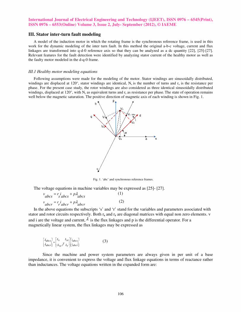
Following assumptions were made for the modeling of the motor. Stator windings are sinusoidally distributed,
windings are displaced at 120°, stator windings are identical, Ns is the number of turns and rs is the resistance per
phase.. For the present case study, the rotor windings are also considered as three identical sinusoidally distributed
windings, displaced at 120°, with Nr as equivalent turns and rr as resistance per phase. The state of operation remains
well below the magnetic saturation. The positive direction of magnetic axis of each winding is shown in Fig. 1.
Fig. 1. ‘abc’ and synchronous reference frames.
The voltage equations in machine variables may be expressed as [25]- [27].
v r i pabcs s abcs abcs
λ= + (1)
v r i pabcr r abcr abcr
λ= + (2)
In the above equations the subscripts ‘s’ and ‘r’ stand for the variables and parameters associated with
stator and rotor circuits respectively. Both rs and rr are diagonal matrices with equal non zero elements. v
and i are the voltage and current, λ is the flux linkages and p is the differential operator. For a
magnetically linear system, the flux linkages may be expressed as
( )
L L is srabcs abcsT iL Labcr abcrsr r
λ
λ
=
(3)
Since the machine and power system parameters are always given in per unit of a base
impedance, it is convenient to express the voltage and flux linkage equations in terms of reactance rather
than inductances. The voltage equations written in the expanded form are:
International Journal of Electrical Engineering and Technology (IJEET), ISSN 0976 – 6545(Print),
ISSN 0976 – 6553(Online) Volume 3, Issue 2, July- September (2012), © IAEME
107
psv r iqs s qs ds qs
b b
ωψ ψ
ω ω= + + (4)
psv r ids s ds qs ds
b b
ωψ ψ
ω ω= − + (5)
0 0 0p
v r is s s sb
ψω
= + (6)
( )
' ' ' ' 'ps rv r iqr r qr dr qr
b b
ω ωψ ψ
ω ω
−= + + (7)
( )
' ' ' ' 'ps rv r idr r dr qr dr
b b
ω ωψ ψ
ω ω
−= − + (8)
' '0 0 0p
v r ir r r rb
ψω
= + (9)
where b
ψλ
ω= in which
bω is the base speed.
The expression for electromagnetic torque developed in the machine in terms of synchronous reference
frame variables is given as
( )3 1
2 2
PT i ids qs qs dse
bψ ψ
ω= − (10)
where P is the number of poles of the machine.
The mechanical equation of the machine is given by
2d rT H T Te L fdt b
ω
ω
= + +
(11)
where H is the inertia constant, TL is the load torque and Tf is the frictional torque of the machine.
22
1 2
2
J bHPP B
ω =
(12)
where PB is the base power of the machine.
Equations (1) to (12) represents the dynamic model of a healthy induction motor, which were used to
simulate in MATLAB/SIMULINK. In the next section, extension of this model, for taking care of the
stator inter-turn fault condition is discussed.
III.2 Modeling the inter-turn fault The mathematical model developed in the q-d-0 reference frame is used for the prediction of inter-turn fault in
the induction machine. When an inter turn short circuit arises, as per the proposed model, the faulty phase is split
into two sub windings located along the same magnetic axis. As a result of this, four voltage equations can be
written for the stator windings. The assumption made in the simplified model is that the distribution of leakage
inductance between the two stator sub windings, originated by the development of the short circuit, is directly
proportional to the square of the number of turns shortcircuited.
The six voltage equations representing the three stator and three rotor windings of the motor shall now be
obtained by merging the two equations related to the winding affected by the fault into just one equation. In addition

International Journal of Electrical Engineering and Technology (IJEET), ISSN 0976 – 6545(Print),
ISSN 0976 – 6553(Online) Volume 3, Issue 2, July- September (2012), © IAEME
108
to this, a voltage equation related to the loop containing the fault is also developed to represent the faulty motor
completely.
All the stator and rotor voltages are then transformed to q-d-0 reference frame and compared with the equations
of healthy machine. Also, the equations for the overall model can be written as the sum of normal supply voltages
and the voltage due to the contribution by the fault. Equations (13) to (25) represents the final voltage equations for
the stator and rotor windings, as well as the short-circuit current and the electromagnetic torque developed by the
motor.
psv v r iqs qs s qs ds qs
b b
ωψ ψ
ω ω+ ∆ = + + (13)
psv v r ids ds s ds qs dsb b
ωψ ψ
ω ω+ ∆ = − + (14)
0 0 0 0p
v v r is s s s sb
ψω
+ ∆ = + (15)
( )' ' ' ' ' '
ps rv v r iqr qr r qr dr qrb b
ω ωψ ψ
ω ω
−+ ∆ = + + (16)
( )' ' ' ' ' '
ps rv v r idr dr r dr qr drb b
ω ωψ ψ
ω ω
−+ ∆ = − + (17)
' '0 0 0p
v r ir r r rb
ψω
= + (18)
where
( )2 3 cos 2 cos3 3
k d kv kL L i r ils ms s sqs s f fdt
θ θ
∆ = + +
(19)
( )2 3 sin 2 sin3 3
k d kv kL L i r ils ms s sds s f fdt
θ θ
∆ = + +
(20)
2
0 3 3
k d kv L i r is ls f s fdt
∆ = + (21)
and
' cos ( sin )d
v kL i is f r s fqr ms dtθ ω θ
∆ = +
(22)
' sin ( cos )d
v kL i is f r s fdr ms dtθ ω θ
∆ = − +
(23)
The intensity of the fault is ‘k’, which is the ratio of the number of shorted turns and the total number of turns in
series per phase and if is the fault current.
It can also be shown that in the faulty loop, the voltage equation shall be:
( )2( ) ( cos sin )0
( )( sin cos ) ( ) cos sin
2( sin cos ) (cos sin )0
dk L L i r kr i kr i i ils ms f f s f s qs s ds s sdt
d dk kL L i i k kL L i is ls M qs s ds s ls M s qs s ds
dt dt
d d dk L i kL i i kL i ils s s M qr s dr s M s qr s drdt dt dt
θ θ
ω θ θ θ θ
ω θ θ θ θ
+ + + = + +
+ + − + + + +
+ − + + +
(24)
Also, the electromagnetic torque can be expressed as
( )3 1( cos sin )
2 2
PT i i pkL i i ids qs qs dse M f dr s qr s
bψ ψ θ θ
ω= − + − (25)
Fig. 2 shows the SIMULINK block diagram of the model of the faulty motor.

International Journal of Electrical Engineering and Technology (IJEET), ISSN 0976 – 6545(Print),
ISSN 0976 – 6553(Online) Volume 3, Issue 2, July- September (2012), © IAEME
109
Fig.2. Complete model block diagram of faulty motor.
IV. Detection of the fault
An efficient and reliable way of the detection of inter-turn fault in induction motors is of great importance today.
Some of the characteristics of the motor, which changes when a fault is developed, are to be identified, which can
serve as the features for the fault detection. In this work, a novel method for the feature extraction for fault detection
from stator current of an induction motor is proposed. It uses the wavelet transform techniques for processing the
stator current data acquired during the fault condition. The trials and tribulations associated with classical signal
processing techniques for non stationary signals can be avoided with this method. Main advantage of this method is
that, for an induction motor with either a constant load or a varying load, this method works efficiently.
IV.1 Theory of Wavelet
To analyze a time-varying signal, several signal processing techniques based on two dimensional time-frequency
domain representation have been proposed. Among them, the short-time Fourier transform (STFT) and wavelet
transform (WT) have been commonly applied for machine fault diagnosis. The STFT of a discrete-time signal x(n)
is defined as,
21
( , ) ( ) ( )
0
knjN
NSTFT k m x n w n m e
n
π−−
= −∑=
(26)
where w(n) is the sliding window.
This inherent relationship between the time and frequency resolutions becomes more critical when the STFT deals
with signals whose frequency content is continuously changing.
To solve the trade-off between time and frequency resolutions of the STFT, the wavelet transform (WT) has been
developed. In contrast to the STFT, the WT uses short windows at high frequencies and long windows for low
frequencies. Using the WT, the time-varying spectra of non-stationary signals can also been obtained in form of
scalograms defined as the squared modulus of the WT.
The signal is multiplied with a function (the wavelet), similar to the window function in the STFT, and the
transform is computed separately for different segments of the time-domain signal.
The wavelet function can be defined at scale ‘a’ and location ‘b’ as
( ),
1a b
t bt
aaψ ψ
− =
(27)
In discrete wavelet transform DWT, the wavelet transform of a continuous time signal x(t) is considered where
discrete values of the dilation and translation parameters, ‘a’ and ‘b’ are used.
A natural way to sample the parameters a and b is to use a logarithmic discretization of the a scale and link this,
in turn, to the size of steps taken between b locations. The discretization of the wavelet has the form

International Journal of Electrical Engineering and Technology (IJEET), ISSN 0976 – 6545(Print),
ISSN 0976 – 6553(Online) Volume 3, Issue 2, July- September (2012), © IAEME
110
( ) 0 0,
0
1
0
m
m n m
t nb at
ama
ψ ψ −
=
(28)
Where the integers m and n control the wavelet dilation and translation respectively; a0 is a specified fixed
dilation step parameter set at a value greater than 1, and b0 is the location parameter which must be greater than zero.
The wavelet transform of a continuous signal, x(t), using discrete wavelet of the form of equation (28) is then
( )1( )
0 0,2
0
mT x t a t nb dtm n m
a
ψ∞
−= −∫−∞
(29)
Where Tm,n are the discrete wavelet transform values given on a scale-location grid of index m,n. For the DWT,
the values of Tm,n are known as wavelet coefficients or detail coefficients.
The accuracy of the WT based feature extraction depends up on the selection of the base function. There are
different families of wavelets that can be used for different applications. The first step of wavelet decomposition is
to select an appropriate wavelet for the signal to be analyzed. Appropriate wavelets should have a wave shape,
which is close to the signal to be analyzed or filtered. The application of wavelet in motor current feature extraction
is described in the next section.
IV.2 Statistical parameters of wavelet coefficients
The wavelet transform is first applied to decompose the original stator current signals into frequency bands. One
of the advantages of the wavelet transform is that it can decompose signals at various resolutions, which allows
accurate feature extraction from non-stationary signals under dynamic load conditions. Once the wavelet
coefficients at various decomposition levels are obtained for the stator current signal, the statistical parameters of
them shall be obtained. The three phase motor stator currents for healthy motor as well as the faulty motor at
different load conditions (ranging from no load to full load) and various fault levels were considered for the feature
extraction. Detailed coefficients up to 6th
level and approximation coefficient at 6th
level of wavelet decomposition
of the stator current signals were extracted. Statistical parameters, such as mean, median, mode, kurtosis,
interquartile range, geometric mean, harmonic mean etc. were then obtained for each of these wavelet coefficients.
Some of these statistical data or parameter properties shall be used to detect the inter-turn fault of the induction
motor, which is explained in the next section.
IV.3 Proposed method
These statistical parameters were analysed at all decomposition levels and load level – fault level
combinations for appropriate feature identification for fault detection. The purpose of the feature extraction process
is to select and retain the relevant information from the signals, which in turn is used to identify the development of
the fault. We have plotted these statistical parameters of detailed as well as approximation wavelet coefficients at
different decomposition levels for the healthy motor as well as the motor with different levels of inter-turn fault at
given load conditions. It is observed that the parameters such as mean, harmonic mean etc. are showing random
variation with reference to the fault levels, which make them non-facet as far as fault detection is concerned. Some
other parameters were showing regular but little variation when the fault is developed. It is observed that the
interquartile range of 6th
level detailed coefficient or 6th
level approximation coefficient of the stator current is
exhibiting regular and wide variation when the fault is developed, qualifying it as one of the best features for the
inter-turn fault detection. Interquartile range is a robust estimate of the spread of the data, which is calculated as the
difference between the 75th and 25th percentiles (3rd
and 1st quartiles) of the wavelet coefficients.
V. HARDWARE SET UP
The hardware used to conduct the experiment consists of three subsystems: the motor under test, loading
mechanism, user interface and data acquisition system. Block diagram of the overall experimental setup is illustrated
in Fig. 3.

International Journal of Electrical Engineering and Technology (IJEET), ISSN 0976 – 6545(Print),
ISSN 0976 – 6553(Online) Volume 3, Issue 2, July- September (2012), © IAEME
111
Fig. 3. Block diagram of the experimental set up.
V.1 Machine set up
A three phase, three horse power induction motor with following details is used in the laboratory setup.
Supply : 3 Phase, 415V, 4.5A, 50Hz, Speed : 1440 rpm stator windings are star connected. The per phase parameters
obtained by conducting proper tests on the motor to are listed as: stator resistance = 3.45Ω/phase, rotor resistance =
3.3302Ω/phase, stator leakage inductance = 0.0152H/phase, rotor leakage inductance = 0.0152H/phase, magnetizing
inductance = 0.2876H/phase. Moment of inertia of the motor is obtained as 0.018kg.m².
The machine used in the experiment is primed for experiments by suitably tapping the stator windings to introduce
inter turn faults. Different stages of alteration are shown in Fig. 4.
Fig. 4. Different stages of fault implementation.
V.2 Current sensor kit
Three hall effect sensors are used as the transducer for the measurement of the stator current. Isolated and regulated
power supplies were developed for supplying the transducer. The sensor board was calibrated for currents ranging
International Journal of Electrical Engineering and Technology (IJEET), ISSN 0976 – 6545(Print),
ISSN 0976 – 6553(Online) Volume 3, Issue 2, July- September (2012), © IAEME
112
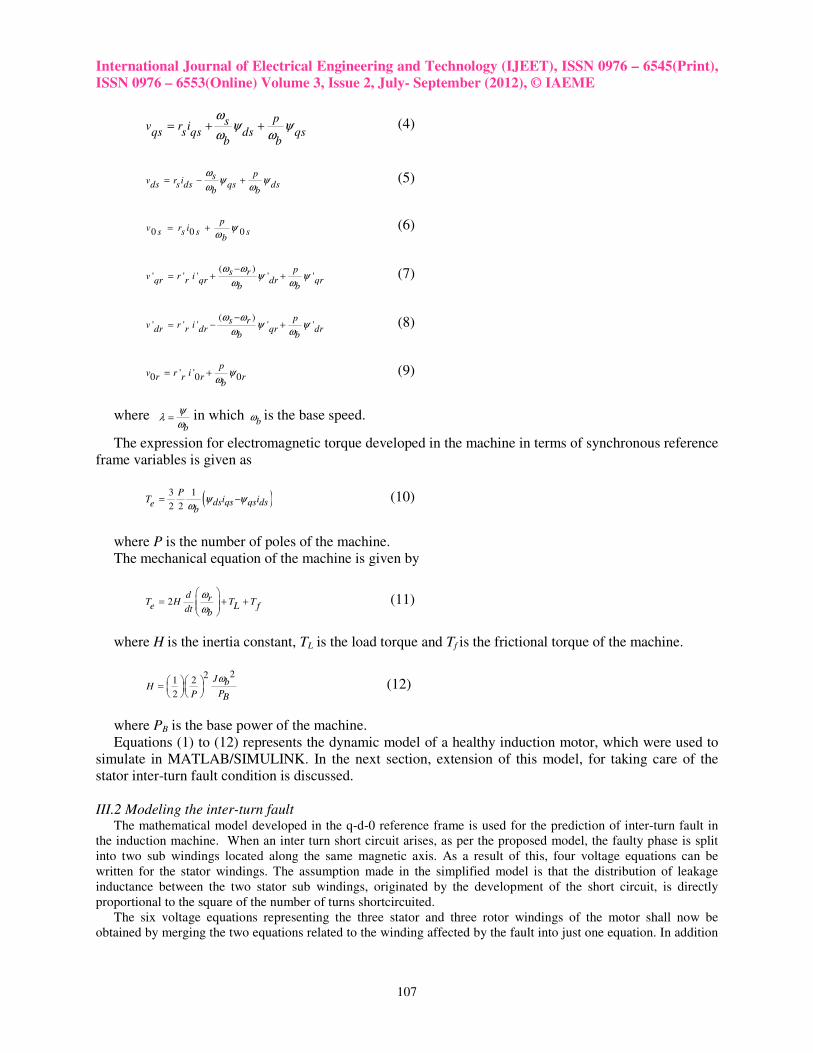
from minimum to maximum to ensure accuracy and linearity in the measurement. Fig.5 shows the current sensor
board used for the experiment.
Fig. 5. Three phase Current sensor board
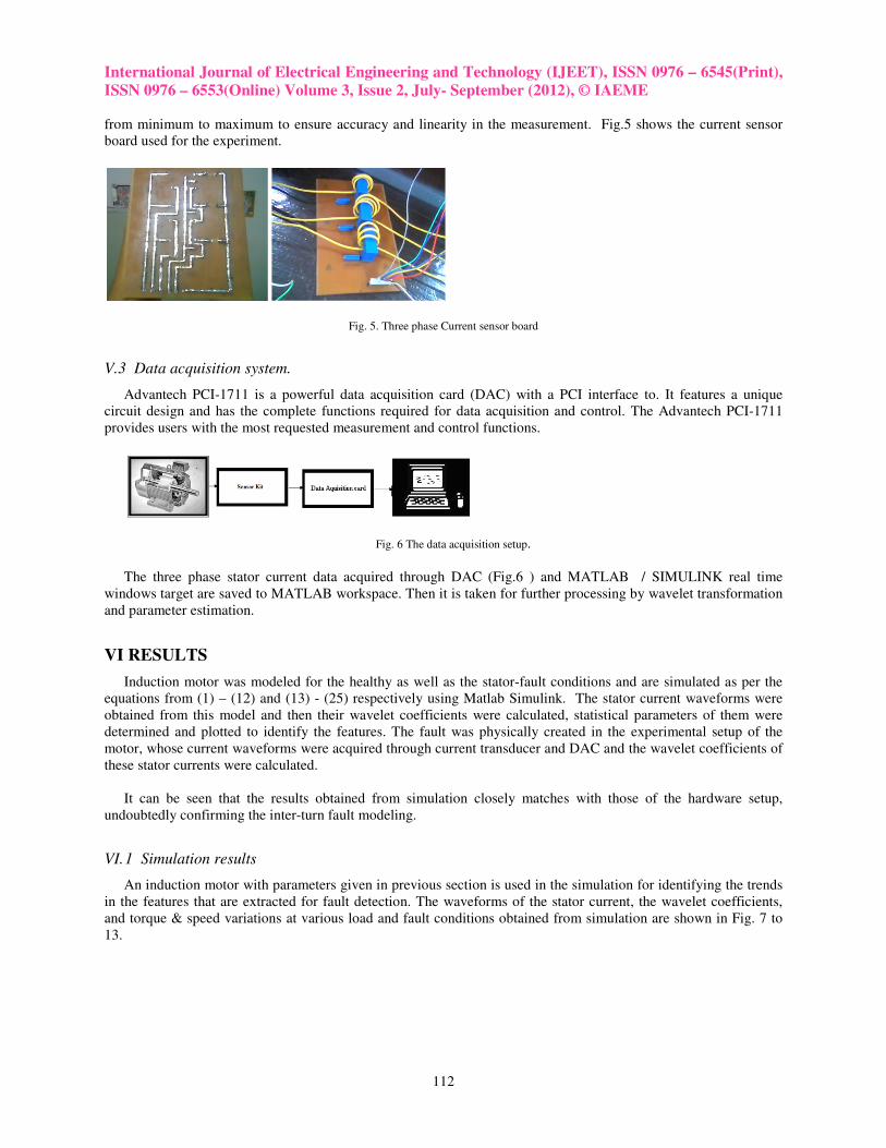
V.3 Data acquisition system.
Advantech PCI-1711 is a powerful data acquisition card (DAC) with a PCI interface to. It features a unique
circuit design and has the complete functions required for data acquisition and control. The Advantech PCI-1711
provides users with the most requested measurement and control functions.
Fig. 6 The data acquisition setup.
The three phase stator current data acquired through DAC (Fig.6 ) and MATLAB / SIMULINK real time
windows target are saved to MATLAB workspace. Then it is taken for further processing by wavelet transformation
and parameter estimation.
VI RESULTS
Induction motor was modeled for the healthy as well as the stator-fault conditions and are simulated as per the
equations from (1) – (12) and (13) - (25) respectively using Matlab Simulink. The stator current waveforms were
obtained from this model and then their wavelet coefficients were calculated, statistical parameters of them were
determined and plotted to identify the features. The fault was physically created in the experimental setup of the
motor, whose current waveforms were acquired through current transducer and DAC and the wavelet coefficients of
these stator currents were calculated.
It can be seen that the results obtained from simulation closely matches with those of the hardware setup,
undoubtedly confirming the inter-turn fault modeling.
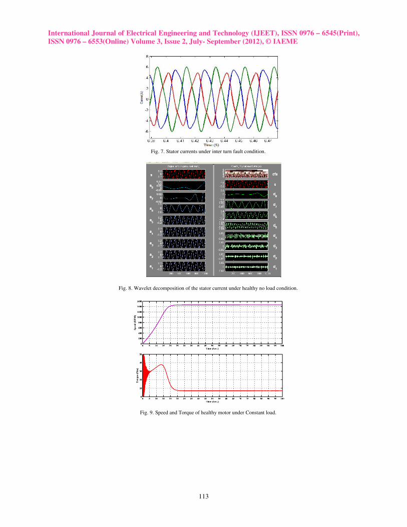
VI. 1 Simulation results
An induction motor with parameters given in previous section is used in the simulation for identifying the trends
in the features that are extracted for fault detection. The waveforms of the stator current, the wavelet coefficients,
and torque & speed variations at various load and fault conditions obtained from simulation are shown in Fig. 7 to
13.
International Journal of Electrical Engineering and Technology (IJEET), ISSN 0976 – 6545(Print),
ISSN 0976 – 6553(Online) Volume 3, Issue 2, July- September (2012), © IAEME
113
Fig. 7. Stator currents under inter turn fault condition.
Fig. 8. Wavelet decomposition of the stator current under healthy no load condition.
Fig. 9. Speed and Torque of healthy motor under Constant load.

International Journal of Electrical Engineering and Technology (IJEET), ISSN 0976
ISSN 0976 – 6553(Online) Volume 3, Issue 2, July
Fig.
Fig. 11.
Fig.
International Journal of Electrical Engineering and Technology (IJEET), ISSN 0976
6553(Online) Volume 3, Issue 2, July- September (2012), © IAEME
114
Fig. 10. Torque and speed of healthy motor for pulsed load.
. Torque and speed of healthy motor under ramping up load.
Fig. 12. Speed and Torque of faulty motor at 3A load.
International Journal of Electrical Engineering and Technology (IJEET), ISSN 0976 – 6545(Print),
International Journal of Electrical Engineering and Technology (IJEET), ISSN 0976 – 6545(Print),
ISSN 0976 – 6553(Online) Volume 3, Issue 2, July- September (2012), © IAEME
115
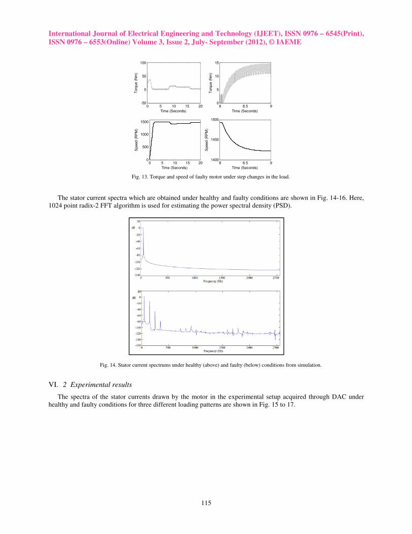
Fig. 13. Torque and speed of faulty motor under step changes in the load.
The stator current spectra which are obtained under healthy and faulty conditions are shown in Fig. 14-16. Here,
1024 point radix-2 FFT algorithm is used for estimating the power spectral density (PSD).
Fig. 14. Stator current spectrums under healthy (above) and faulty (below) conditions from simulation.
VI. 2 Experimental results
The spectra of the stator currents drawn by the motor in the experimental setup acquired through DAC under
healthy and faulty conditions for three different loading patterns are shown in Fig. 15 to 17.
0 5 10 15 20-50
0
50
100
Time (Seconds)
Torq
ue (
Nm
)
0 5 10 15 200
500
1000
1500
Time (Seconds)
Speed (
RP
M)
8 8.5 90
5
10
15
Time (Seconds)
Torq
ue (
Nm
)
8 8.5 91400
1450
1500
Time (Seconds)
Speed (
RP
M)
International Journal of Electrical Engineering and Technology (IJEET), ISSN 0976 – 6545(Print),
ISSN 0976 – 6553(Online) Volume 3, Issue 2, July- September (2012), © IAEME
116
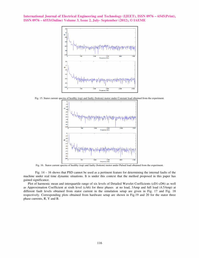
Fig. 15. Stator current spectra of healthy (top) and faulty (bottom) motor under Constant load obtained from the experiment.
Fig. 16. Stator current spectra of healthy (top) and faulty (bottom) motor under Pulsed load obtained from the experiment.
Fig. 14 – 16 shows that PSD cannot be used as a pertinent feature for determining the internal faults of the
machine under real time dynamic situations. It is under this context that the method proposed in this paper has
gained significance.
Plot of harmonic mean and interquartile range of six levels of Detailed Wavelet Coefficients (cD1-cD6) as well
as Approximation Coefficient at sixth level (cA6) for three phases at no load, 3Amp and full load (4.5Amp) at
different fault levels obtained from stator current in the simulation setup are given in Fig. 17 and Fig. 18
respectively. Corresponding plots obtained from hardware setup are shown in Fig.19 and 20 for the stator three
phase currents, R, Y and B.

International Journal of Electrical Engineering and Technology (IJEET), ISSN 0976 – 6545(Print),
ISSN 0976 – 6553(Online) Volume 3, Issue 2, July- September (2012), © IAEME
117
-10
-8
-6
-4
-2
0
2
4
1 2 3 4 5 6 7 8
Ha
rMe
an
HarMean 4.5A R Phase
cD1
cD2
cD3
cD4
cD5
cD6
cA6-10
-8
-6
-4
-2
0
2
1 2 3 4 5 6 7 8
Ha
rMe
an
HarMean 4.5A Y Phase
cD1
cD2
cD3
cD4
cD5
cD6
cA6
-3
-2
-1
0
1
2
3
4
5
1 2 3 4 5 6 7 8
Ha
rMe
an
HarMean 4.5A B Phase
cD1
cD2
cD3
cD4
cD5
cD6
cA6-6
-4
-2
0
2
4
6
1 2 3 4 5 6 7 8Ha
rMe
an
HarMean 3A R Phase
cD1
cD2
cD3
cD4
cD5
cD6
cA6
-6
-4
-2
0
2
4
6
8
10
1 2 3 4 5 6 7 8
Ha
rMe
an
HarMean 3A Y Phase
cD1
cD2
cD3
cD4
cD5
cD6
cA6-10
-8
-6
-4
-2
0
2
4
1 2 3 4 5 6 7 8
Ha
rMe
an
HarMean 3A B Phase
cD1
cD2
cD3
cD4
cD5
cD6
cA6
-10
-5
0
5
10
15
1 2 3 4 5 6 7 8
Ha
rMe
an
Interturn Fault Levels
HarMean : At No load - R Phase
cD1
cD2
cD3
cD4
cD5
cD6
cA6
-10
-5
0
5
1 2 3 4 5 6 7 8
Ha
rMe
an
Interturn Fault Levels
HarMean : At No load - Y Phase
cD1
cD2
cD3
cD4
cD5
cD6
cA6
-10
-5
0
5
10
1 2 3 4 5 6 7 8Ha
rMe
an
Interturn Fault Levels
HarMean : At No load - B Phase
cD1
cD2
cD3
cD4
cD5
cD6
cA6
Fig. 17 Simulation Result :- Harmonic mean of Detailed coefficients (cD1 – cD6) and the Approximation coefficient (cA6) at full load, 3A load
and no load for various fault levels for R, Y and B phase currents obtained from Simulation. Data points 1&2 belongs to healthy motor, 3&4 for
the faulty motor with 150k fault resistance 5&6 are faulty motor with 1k fault resistance and 7&8 are faulty motor with 100 Ohm fault resistance.
0
1
2
3
4
5
6
1 2 3 4 5 6 7 8
iqr
iqr 4.5A R Phase
cD1
cD2
cD3
cD4
cD5
cD6
cA60
1
2
3
4
5
6
1 2 3 4 5 6 7 8
iqr
iqr 4.5A Y Phase
cD1
cD2
cD3
cD4
cD5
cD6
cA6
0
1
2
3
4
5
1 2 3 4 5 6 7 8
iqr
iqr 4.5A B Phase
cD1
cD2
cD3
cD4
cD5
cD6
cA6
0
0.5
1
1.5
2
2.5
3
3.5
4
1 2 3 4 5 6 7 8
iqr
Interturn Fault Levels
iqr : At 3A load - R Phase
cD1
cD2
cD3
cD4
cD5
cD6
cA6
International Journal of Electrical Engineering and Technology (IJEET), ISSN 0976 – 6545(Print),
ISSN 0976 – 6553(Online) Volume 3, Issue 2, July- September (2012), © IAEME
118
0
0.5
1
1.5
2
2.5
3
3.5
4
1 2 3 4 5 6 7 8
iqr
Interturn Fault Levels
iqr : At 3A load - Y Phase
cD1
cD2
cD3
cD4
cD5
cD6
cA6
0
0.5
1
1.5
2
2.5
3
3.5
1 2 3 4 5 6 7 8
iqr
Interturn Fault Levels
iqr : At 3A load - B Phase
cD1
cD2
cD3
cD4
cD5
cD6
cA6
0
0.5
1
1.5
2
2.5
3
3.5
1 2 3 4 5 6 7 8
iqr
Interturn Fault Levels
iqr : At No load - R Phase
cD1
cD2
cD3
cD4
cD5
cD6
cA6
0
0.5
1
1.5
2
2.5
3
3.5
1 2 3 4 5 6 7 8
iqr
Interturn Fault Levels
iqr : At No load - Y Phase
cD1
cD2
cD3
cD4
cD5
cD6
cA6
0
0.5
1
1.5
2
2.5
3
1 2 3 4 5 6 7 8
iqr
Interturn Fault Levels
iqr : At No load - B Phase
cD1
cD2
cD3
cD4
cD5
cD6
cA6
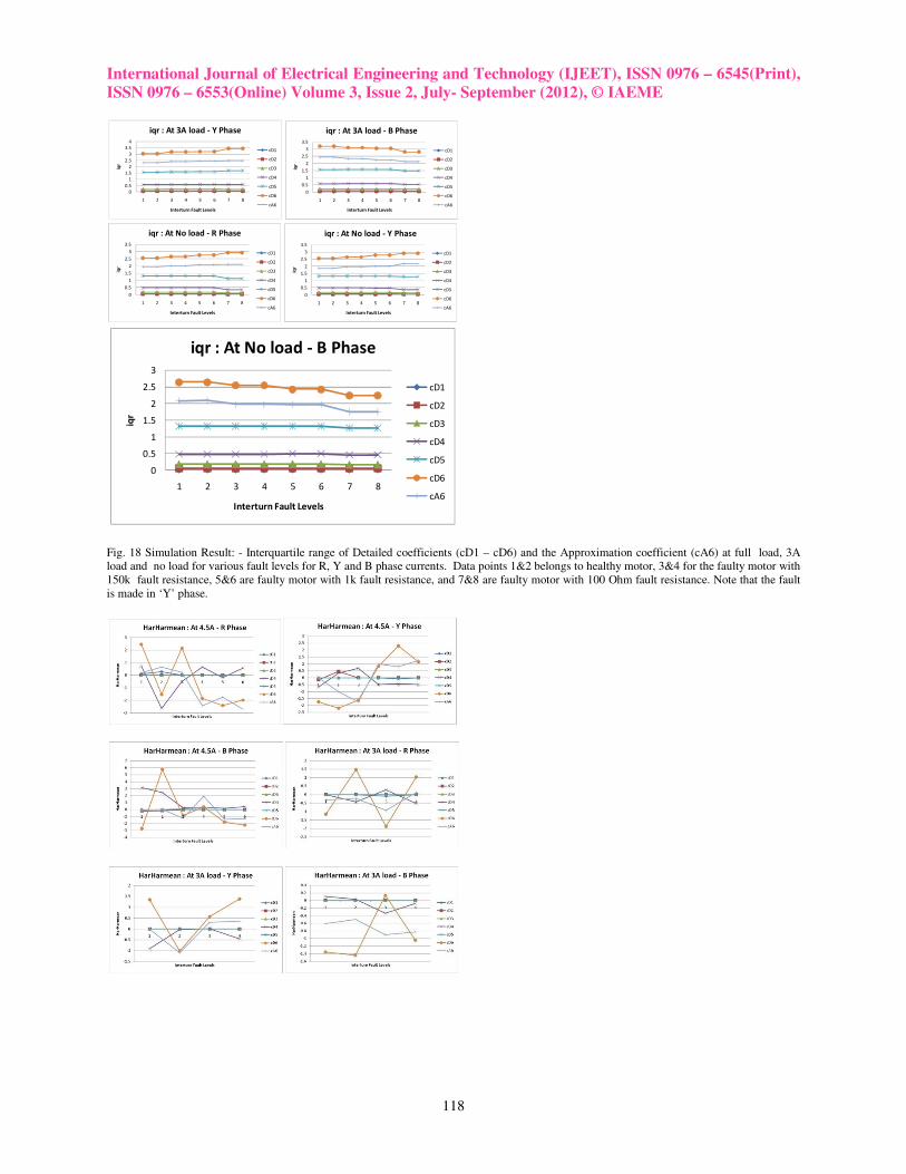
Fig. 18 Simulation Result: - Interquartile range of Detailed coefficients (cD1 – cD6) and the Approximation coefficient (cA6) at full load, 3A
load and no load for various fault levels for R, Y and B phase currents. Data points 1&2 belongs to healthy motor, 3&4 for the faulty motor with
150k fault resistance, 5&6 are faulty motor with 1k fault resistance, and 7&8 are faulty motor with 100 Ohm fault resistance. Note that the fault
is made in ‘Y’ phase.

International Journal of Electrical Engineering and Technology (IJEET), ISSN 0976 – 6545(Print),
ISSN 0976 – 6553(Online) Volume 3, Issue 2, July- September (2012), © IAEME
119
Fig. 19 Harmonic mean of Detailed coefficients (cD1 – cD6) and the Approximation coefficient (cA6) at full load, 3A load and no load for
various fault levels for R, Y and B phase currents obtained from Hardware setup. Data points 1&2 belongs to healthy motor, 3&4 for the faulty
motor with 150k fault resistance and 5&6 are faulty motor with 1k fault resistance.
International Journal of Electrical Engineering and Technology (IJEET), ISSN 0976 – 6545(Print),
ISSN 0976 – 6553(Online) Volume 3, Issue 2, July- September (2012), © IAEME
120
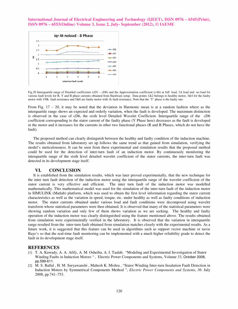
Fig.20 Interquartile range of Detailed coefficients (cD1 – cD6) and the Approximation coefficient (cA6) at full load, 3A load and no load for
various fault levels for R, Y and B phase currents obtained from Hardware setup. Data points 1&2 belongs to healthy motor, 3&4 for the faulty
motor with 150k fault resistance and 5&6 are faulty motor with 1k fault resistance. Note that the ‘Y’ phase is the faulty one.
From Fig. 17 – 20, it may be noted that the deviation in Harmonic mean is at a random fashion where as the
interquartile range shows an expected and orderly variation, when the fault is developed. The maximum distinction
is observed in the case of cD6, the sixth level Detailed Wavelet Coefficient. Interquartile range of the cD6
coefficient corresponding to the stator current of the faulty phase (Y Phase here) decreases as the fault is developed
in the motor and it increases for the currents in other two functional phases (R and B Phases, which do not have the
fault).
The proposed method can clearly distinguish between the healthy and faulty condition of the induction machine.
The results obtained from laboratory set up follows the same trend as that gained from simulation, verifying the
model’s meticulousness. It can be seen from these experimental and simulation results that the proposed method
could be used for the detection of inter-turn fault of an induction motor. By continuously monitoring the
interquartile range of the sixth level detailed wavelet coefficient of the stator currents, the inter-turn fault was
detected in its development stage itself.
VI. CONCLUSION It is established from the simulation results, which was later proved experimentally, that the new technique for
the inter turn fault detection of the induction motor using the interquartile range of the wavelet coefficient of the
stator current is very effective and efficient. The inter turn fault of the induction motor was modelled
mathematically. This mathematical model was used for the simulation of the inter-turn fault of the induction motor
in SIMULINK (Matlab) platform, which was used to obtain the first level information regarding the stator current
characteristics as well as the variation in speed, torque, etc. under healthy as well as faulty conditions of induction
motor. The stator currents obtained under various load and fault conditions were decomposed using wavelet
transform whose statistical parameters were then obtained. It is observed that many of the statistical parameters were
showing random variation and only few of them shows variation as we are seeking. The healthy and faulty
operation of the induction motor was clearly distinguished using the feature mentioned above. The results obtained
from simulation were experimentally verified in the laboratory. It is observed that the variation in interquartile
range resulted from the inter-turn fault obtained from simulation matches closely with the experimental results. As a
future work, it is suggested that this feature can be used in algorithms such as support vector machine or navie
Baye’s so that the real-time fault monitoring can be implemented with a much higher reliability grade to detect the
fault in its development stage itself.
REFERENCES [1] T. A. Kawady, A. A. Afify, A. M. Osheiba, A. I. Taalab, “Modeling and Experimental Investigation of Stator
Winding Faults in Induction Motors “ , Electric Power Components and Systems, Volume 33, October 2008,
pp.599-611. [2] M. S. Ballal , H. M. Suryawanshi , Mahesh K. Mishra , “Stator Winding Inter-turn Insulation Fault Detection in
Induction Motors by Symmetrical Components Method ”, Electric Power Components and Systems, 36: July
2008, pp.741–753.
International Journal of Electrical Engineering and Technology (IJEET), ISSN 0976 – 6545(Print),
ISSN 0976 – 6553(Online) Volume 3, Issue 2, July- September (2012), © IAEME
121
[3] A.H. Bonnett, G.C.Soukup, “Cause and Analysis of Stator and Rotor Failures in Three- Phase Squirrel-Cage
Induction Motors,” IEEE Transactions on Industry Applications, vol. 28 No. 4, July/August 1992, pp.921-937.
[4] Jordi Cusido, Luis Romeral, J A Ortega, J A Rosero and A G Espinosa, “Fault Detection in Induction Machines
Using Power Spectral Density in Wavelet Decomposition”, IEEE Transactions on Industrial Electronics,
Vol.55, N0.2, February 2008, pp 633-643.
[5] B.Liang, B.S.Payne, A.D.Ball and S.D.Iwnicki, “Simulation and fault detection of three-phase induction
motors”, Journal in Mathematics and Computers in Simulation 61 (2002) 1–15.
[6] Arfat Siddique, G. S. Yadava, and Bhim Singh, “A Review of Stator Fault Monitoring Techniques of
Induction Motors”, IEEE Transactions on Energy conversions, Vol. 20, No. 1, March 2005, pp.106-114.
[7] Sergio M. A. Cruz and A. J. Marques Cardoso, “Diagnosis of Stator Inter-Turn Short Circuits in DTC
Induction Motor Drives”, IEEE Transactions on Industry Applications, Vol. 40, September/October 2004,
pp.349-1360.
[8] S. B. Lee, R. M. Tallam, and T. G. Habetler, “A robust, on-line turn-fault detection technique for induction
machines based on monitoring the sequence component impedance matrix,” IEEE Transactions Power
Electronics, Vol. 18, No. 3, May 2003, pp. 865-872
[9] M. Sahraoui, A. Ghoggal, S. E. Zouzou, A. Aboubou and H. Razik, “Modelling and Detection of Inter-Turn
Short Circuits in Stator Windings of Induction Motor”, IEEE Industrial Electronics, IECON 2006-32nd
Annual
Conference of IEEE, 6-10,Nov 2006, pp.4981-4986.
[10] G.G. Acosta, C.J. Verucchi and E.R. Gelso, “Current Monitoring System for Diagnosing Electrical Failures in
Induction Motors”, Journal in Mechanical Systems and Signal Processing 20 (2006), pp.953–965.
[11] Jesper S. Thomsen and Carsten S. Kallesøe, “Stator Fault Modelling of Induction Motors”, SPEEDAM 2006,
International Symposium on Power Electronics, Electrical Drives, Automation and Motion, S9, pp.6-11.
[12] Sergio M. A. Cruz and A. J. Marques Cardoso, “Multiple Reference Frames Theory: A New Method for the
Diagnosis of Stator Faults in Three-Phase Induction Motors”, IEEE Transactions on Energy conversions, Vol.
20, No. 3, September 2005.
[13] Xu Bo-qiang, LI He-mhg, SUN Li-hg, “Detection of Stator Winding Inter-turn Short Circuit Fault in Induction
Motors”, 2004 International Conference on Power System Technology - POWERCON 2004 Singapore, 21-24
November 2004, pp.1005-1009.
[14] Andreas Stavrou, Howard G. Sedding, and James Penman, “Current Monitoring for Detecting Inter-Turn Short
Circuits in Induction Motors”, IEEE Transactions on Energy Conversion, Vol.16, No: 1, pp.32-37, March 2001.
[15] Mehrdad Heidari, Davar Mirabbasi, S. Ghodrattollah Seifossadat, Reza Kianinezhad, “Comparison and
Detection of Abnormal Conditions in Induction Motors”, International Review of Electrical Engineering, Vol.
3. n. 5, October 2010 (part A), pp. 803-808
[16] Gojko M. Joksimovic and Jim Penman, “The Detection of Inter-Turn Short Circuits in the Stator Windings of
Operating Motors”, IEEE Transactions on Industrial Electronics, VOL. 47, NO. 5, October 2000, pp.1078-
1084.
[17] R. M. Tallam, T. G. Habetler, and R. G. Harley, “Transient model for induction machines with stator winding
turn faults,” IEEE Transactions on Industry Application, Vol. 38, May/June 2002, pp. 304-309.
[18] Sami Ekici, Selcuk Yildirim and Mustafa Poyraz, “Energy and entropy-based feature extraction for locating
fault on transmission lines by using neural network and wavelet packet decomposition”, Journal on Expert
Systems with Applications 34 (2008), pp. 2937–2944.
[19] Murat Uyar, Selcuk Yildirim, Muhsin Tunay Gencoglu, “An effective wavelet-based feature extraction method
for classification of power quality disturbance signals”, Electric Power Systems Research 78, (2008), pp. 1747–
1755.
[20] M. Rachek, Y. Méssaoudi, B. Oukacine , S. NaitLarbi, “Accurate Multi-Turn Model of Induction Motors
Under Stator Short Circuits and Phases Breakdown Faults”, International Review of Electrical Engineering,
Vol. 1 n. 1, October 2008, PP 154 – 162.
[21] Matsuyama, A. Jonkman, M., “The Application of Wavelet and Feature Vectors to ECG Signals”, TENCON
2005 - 2005 IEEE Region 10 Conferenc, 21-24 Nov. 2005, pp 1-4.
[22] H. Merabet, T. Bahi, Y. Soufi, “Diagnosis of Rotor Faults in Induction Motor”, International Review of
Electrical Engineering, August 2010, Vol. 3. n. 4, pp. 518-524.
[23] A. Metatla, S. Benzahioul, T. Bahi, D. Lefebvre, “Eccentricity Fault Monitoring by Analysis Stator Phase
Currents”, International Review of Electrical Engineering, Vol. 3. n. 4, August 2010, pp. 533-537.
[24] P. Zhou, W. N. Fu, D. Lin, S. Stanton, Z. J. Cendes and Longya Xu, “Numerical Modeling of Electrical
Machines and Its Application”, University of British Colombia, Electrical and Computer Engg. Dept website.

International Journal of Electrical Engineering and Technology (IJEET), ISSN 0976 – 6545(Print),
ISSN 0976 – 6553(Online) Volume 3, Issue 2, July- September (2012), © IAEME
122
[25] Paul S Addison, The Illustrated Wavelet Transform Handbook, Introductory theory and Applications in Science,
Engineering, Medicine and Finance, (Institute of Physics Publishing Bristol and Philadelphia, 2002.)
[26] Paul C Krause, Oleg Wasynczuk and Scott D Sudoff, Analysis of Electric Machinery and Drive systems, (John
Wiley & Sons (ASIA) Pvt. Ltd., 2nd
Edition, 2010.)
[27] R Krishnan, Electric motor drives: Modeling, Analysis and Control (Pearson Prentice HallTM
, 2001)
Nomenclature
Vd Direct Component of voltage
Vq Quadrature Component of voltage
PB base power of the machine
Ns number of turns in stator per phase
λ flux linkage
H inertia constant
p differential operator
TL load torque
bω base speed
Tf frictional torque
En(s) wavelet energy
E(s) Shannon entropy
rs stator resistance per phase
Authors’ information Affiliation :
1,2,3,4 Electrical Engineering Department,
National Institute Of Technology, Calicut.
Mr. Jagadanand G was born in Calicut, Kerala, India in the year 1968. He had completed his B Tech degree in Electrical
And Electronics Engineering from NSS College Of Engineering, Palakkad, University of Calicut, Kerala, India, and M Tech
in Power Electronic iin Nov 1992 from Regional Engineering college (REC), Calicut, Kerala, India. His research interest
include DSP, Processors, Machine modeling. Mr. Jagadanand is a member of IEEE as well as ISTE.
Mr. Lalgy Gopi was born in Kochi, Kerala, India in the year 1984. He received the B.Tech Degree in Electrical and
Electronics Engineering from the Mahatma Gandhi University, Kottayam, Kerala, India in 2006 and the M.Tech Degree in
Power Electronics from National Institute of Technology (NIT), Calicut, India in 2009.
He has been with the Department of Electrical and Electronics Engineering of Saintgits College of Engineering as Lecturer in
from 2006 to 2010. Presently he is working in the Power Generation wing of the state electricity board (KSEB) of Kerala as
Assistant Engineer. His area of interest includes Electrical machines and drives, Power Electronics, FACTS and Power
Quality.
Dr. Saly George was born in Pathanamthitta, Kerala, India, in the year 1960. She received her B-Tech degree in Electrical
and Electronics in 1982 from College of Engineering, Trivandrum, Kerala and M-Tech in Power Electronics from Regional
Engineering College (REC), Calicut, Kerala, India in 1990. Her area of interest include Power Electronics Circuits and
Control, SMPS etc..Dr. Saly is a member of IEEE.
Dr.Jeevamma Jacob was born in Ernakulam, Kerala, India in the year 1961. She had completed her B.Sc Engg degree in
Electrical Engineering fr om University of Kerala in the year 1983, M.Tech in Control System from REC Calicut in the
year 1985 and Ph.D from IIT Bombay in the year 1994. Her area of interest include Multi variable Control, Digital contro
and DSP.. Dr.Jeevamma is a member of IEEE.