11 HANDLING POST INSULATION - isoplus-pipes.com · 11.5 Check List for Post Insulation 11.5.1...
19
internet: www.isoplus.org Edition: 16.01.2012 11.1 General 11.1.1 Description....................................................................................................... 11 / 1 11.2 Assembling Tools 11.2.1 Survey............................................................................................................... 11 / 2-4 11.3 Assembling Connection Coupler 11.3.1 PEHD - Shrinkable Coupler.............................................................................. 11 / 5 11.3.2 isojoint X - Shrinkable Coupler....................................................................... 11 / 6 11.3.3 isojoint III - Shrinkable Coupler...................................................................... 11 / 7 11.3.4 Electro - Welding Coupler............................................................................... 11 / 8 11.3.5 isocompact - Coupler..................................................................................... 11 / 9 11.3.6 Spiro - Coupler................................................................................................. 11 / 10 11.3.7 Reduction - Shrinkable Coupler....................................................................... 11 / 11 11.3.8 Double Reduction - Shrinkable Coupler........................................................... 11 / 11 11.3.9 Shrinkable End Coupler.................................................................................... 11 / 11 11.3.10 Assembling Connection Coupler / Assembling Parts....................................... 11 / 12 11.3.11 Assembling Half-Shells..................................................................................... 11 / 13 11.4 PUR - Foam Table 11.4.1 Foam-Table....................................................................................................... 11 / 14 11.5 Check List for Post Insulation 11.5.1 Building Site - Quality Assurance...................................................................... 11 / 15-16 11.5.2 isoplus-Assembling Conditions......................................................................... 11 / 17-18 11 HANDLING POST INSULATION 11
Transcript of 11 HANDLING POST INSULATION - isoplus-pipes.com · 11.5 Check List for Post Insulation 11.5.1...

internet: www.isoplus.orgEd
ition
: 16.
01.2
012
11.1 General
11.1.1 Description....................................................................................................... 11 / 1
11.2 Assembling Tools
11.2.1 Survey............................................................................................................... 11 / 2-4
11.3 Assembling Connection Coupler
11.3.1 PEHD - Shrinkable Coupler.............................................................................. 11 / 5 11.3.2 isojoint X - Shrinkable Coupler....................................................................... 11 / 6 11.3.3 isojoint III - Shrinkable Coupler...................................................................... 11 / 7 11.3.4 Electro - Welding Coupler............................................................................... 11 / 8 11.3.5 isocompact - Coupler..................................................................................... 11 / 9 11.3.6 Spiro - Coupler................................................................................................. 11 / 10 11.3.7 Reduction - Shrinkable Coupler....................................................................... 11 / 11 11.3.8 Double Reduction - Shrinkable Coupler........................................................... 11 / 1111.3.9 Shrinkable End Coupler.................................................................................... 11 / 1111.3.10 Assembling Connection Coupler / Assembling Parts....................................... 11 / 1211.3.11 Assembling Half-Shells..................................................................................... 11 / 13
11.4 PUR - Foam Table
11.4.1 Foam-Table....................................................................................................... 11 / 14
11.5 Check List for Post Insulation
11.5.1 Building Site - Quality Assurance...................................................................... 11 / 15-1611.5.2 isoplus-Assembling Conditions......................................................................... 11 / 17-18
11 HANDLING POST INSULATION
11

Ed
ition
: 16.
01.2
012
Copy only after permission of isoplus Fernwärmetechnik Vertriebsgesellschaft mbH; modifi cations reserved
internet: www.isoplus.org 11 / 1
11.1.1 Description
All carrier pipe connections have to be insulated and sealed with connection couplers and PUR-foam after recording of the agreed pressure tests. For warranty reasons these works, except of isocompact-coupler, should be carried out by isoplus-educated assembling specialists, approved by AGFW- and BFW institute. The isocompact-coupler may be used by the pipe laying company for independent post-insulation at the connection spots, except of double pipes.
All coupler connections made by isoplus will be clearly and durable marked by the installer, this includes:
Date of foaming Length of coupler (hollow space) Assembling date of sleeves Name of installer Resistance values IPS-Cu or IPS-NiCr
This mark will allow a detailed identifi cation of the executing installer and will increase the quality safety with their requirements. In case that the post-insulation should be nevertheless carried out by a third party, their ability has to be checked by presenting the AGFW-/BFW-test certifi cate before starting the assembling work. isoplus has to be informed about this in advance.
Current assembly-instructions of all isoplus connection-couplers are available in our download-section at www.isoplus.org .Detailed information on wiring the leak detection and the differing wiring regulations for branching, as well as tables for the foam quantities to be used for the differing casing joint types, are also available in this section.
The preparing working steps 1. to 11. are valid concerning all coupler constructions delivered by isoplus. Additionally the isoplus-assembling conditions, see chapter 11.5.2 have generally to be considered.
ATTENTION: Assembling works have to be carried out always with working overall and if necessary with gloves and protection glasses as well as in accordance with the general regulations for preventing accidents (UVV) requested protection clothes.
11 HANDLING POST INSULATION11.1 General

internet: www.isoplus.org Ed
ition
: 16.
01.2
012
Copy only after permission of isoplus Fernwärmetechnik Vertriebsgesellschaft mbH; modifi cations reserved11 / 2
11.2.1 Survey
# Coupler construction / -typePEHD
Shrinkableisojoint X isojoint III Electro-
Weldingisocompact Spiro
1 Pressure set with pump and manometer 2 Workman’s overall
3 Working gloves
4 Binding wire
5 Drilling set, ø = 4, 6 and 10 mm
6 Drilling machine (Akku or 230 V)
7 Triangular scraper
8 High-grade-steel strap retainer
9 Gas-burner set eventual10 Hammer, ca. 150 gramme
11 Hand-broom
12 Wood-driller with stopper
13 Insulation adhesive tape, 40 mm, if required
14 Cable drum, if required
15 Cartouche-press, if required
16 Marker, white + black (water resistant)
17 Measuring tape and meter stick
18 Tongs for rivets
19 PE-burr-remover resp. -scraper
20 PE-cleaner resp. fat solvent
21 Propane-liquid gas bottle eventual22 Cleaning rag, fl uffy free
23 Umbrella if required
24 Stirring set for drilling machine
25 Hand-saw eventual eventual26 Peel-driller, conical, size M 3
27 Foaming machine, starting from Da ≥ 315 mm
28 Scissors
29 Emery linen, 50 mm, grain 60
30 Set of screwdrivers, kirve and cross
31 Protecting glasses
32 Welding transformer / -machine (400 V)
33 Welding pincers
34 Stretch band, at least 2 pieces eventual
35 Sprayer with soap-water
36 Steel brush
37 Mortise chisel
38 Compass saw eventual39 Plug-welding machine(230 V)
40 Current aggregate, if required
41 Tapestry roller
42 Temperature probe eventual43 Carpet knife
# Assembling fi tting Coupler Elbow Branch
52 Extruder welding unit (220 V), starting from Da = 225 mm 53 Hot-air welding unit (220 V), up to Da = 200 mm 54 PE-welding wire 34 Stretch bands
# Type of leak detecting IPS-Cu IPS-NiCr
45 Wire distance holder, per coupler 2 pieces 46 Electro pincer set (strip the insulation, press, cutter, kombi)
47 isoplus-hand-system tester, type IPS-HST
48 Soldering burner
49 Soldering tin
50 Pinch husks
51 Shrinking tube
11 HANDLING POST INSULATION11.2 Assembling Tools

Ed
ition
: 16.
01.2
012
Copy only after permission of isoplus Fernwärmetechnik Vertriebsgesellschaft mbH; modifi cations reserved
internet: www.isoplus.org 11 / 3
# 1 # 2 # 3 # 4
# 5 # 6 # 7 # 8
# 9 # 10 # 11 # 12
# 13 # 14 # 15 # 16 # 17
# 18 # 19 # 20 # 21 # 22
# 23 # 25
# 27# 24 # 26
11 HANDLING POST INSULATION11.2 Assembling Tools
# 8
# 9 # 12
# 14 # 15 # 16
# 18 # 19 # 20
# 23
# 24 # 27

internet: www.isoplus.org Ed
ition
: 16.
01.2
012
Copy only after permission of isoplus Fernwärmetechnik Vertriebsgesellschaft mbH; modifi cations reserved11 / 4
11 HANDLING POST INSULATION11.2 Assembling Tools
# 28
# 29 # 32 # 34
# 30 # 31 # 33 # 35
# 36 # 37 # 38 # 39
# 40 # 41 # 42 # 43
# 45 # 47 # 50
# 46 # 48 # 49 # 51
# 52 # 53 # 54
# 32# 32
# 33
# 37 # 38 # 39
# 45 # 47
# 46
# 52 # 53

Ed
ition
: 16.
01.2
012
Copy only after permission of isoplus Fernwärmetechnik Vertriebsgesellschaft mbH; modifi cations reserved
internet: www.isoplus.org 11 / 5
11.3.1 PEHD - Shrinkable Coupler
Working Procedure
11 HANDLING POST INSULATION11.3 Assembling Connection Coupler
Technical description see chapter 6.2.2
Current assembly-instructions of the PEHD-Shrinkable Coupler are available in our download-section at www.isoplus.org .
two shrink-sleeves
two PE-venting- andweldable plugs each
two heat shrinkable PE-hole-lockers
Butyl-rubber-sealing tape
Heat-shrinkable PEHD-pipe

internet: www.isoplus.org Ed
ition
: 16.
01.2
012
Copy only after permission of isoplus Fernwärmetechnik Vertriebsgesellschaft mbH; modifi cations reserved11 / 6
11.3.2 isojoint X - Shrinkable Coupler
11 HANDLING POST INSULATION11.3 Assembling Connection Coupler
Butyl-rubber-sealing tape
two PE-venting- andweldable plugs each
Heat-shrinkable cross linkedPEHD-pipe
Technical description see chapter 6.3.2
Current assembly-instructions of the isojoint X-Shrinkable coupler are available in our download-section at www.isoplus.org .
Working Procedure

Ed
ition
: 16.
01.2
012
Copy only after permission of isoplus Fernwärmetechnik Vertriebsgesellschaft mbH; modifi cations reserved
internet: www.isoplus.org 11 / 7
11.3.3 isojoint III - Shrinkable Coupler
11 HANDLING POST INSULATION11.3 Assembling Connection Coupler
Working Procedure
Butyl-rubber-sealing tape,extra wide
Heat-shrinkable cross linkedPEHD-pipe
PE-X-shrinking foil with sealing compound
Technical description see chapter 6.4.2
Current assembly-instructions of the isojoint III - Shrinkable coupler are available in our download-section at www.isoplus.org .

internet: www.isoplus.org Ed
ition
: 16.
01.2
012
Copy only after permission of isoplus Fernwärmetechnik Vertriebsgesellschaft mbH; modifi cations reserved11 / 8
11.3.4 Electro - Welding Coupler
11 HANDLING POST INSULATION11.3 Assembling Connection Coupler
Working procedure
Technical description see chapter 6.5.2
Current assembly-instructions of the Electro - Welding coupler are available in our download-section at www.isoplus.org .
two processor controlled copper-heat
conductors
two PE- venting- andweldable plugs each
two heat shrinkable PE-hole-lockers
Heat-shrinkable PEHD-pipe
Ed
ition
: 16.
01.2
012
Copy only after permission of isoplus Fernwärmetechnik Vertriebsgesellschaft mbH; modifi cations reserved
internet: www.isoplus.org 11 / 9
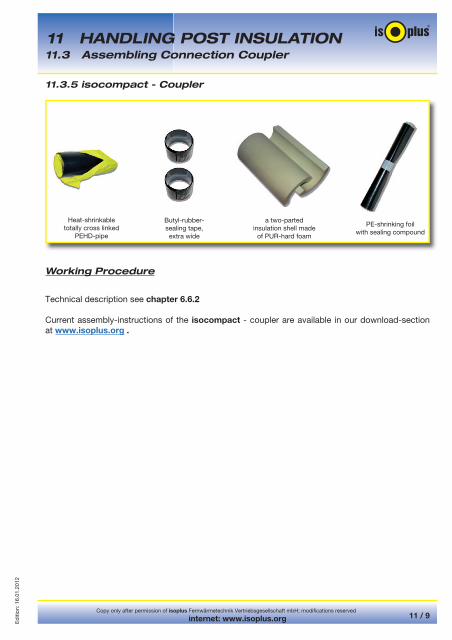
11.3.5 isocompact - Coupler
11 HANDLING POST INSULATION11.3 Assembling Connection Coupler
Working Procedure
Technical description see chapter 6.6.2
Current assembly-instructions of the isocompact - coupler are available in our download-section at www.isoplus.org .
Butyl-rubber-sealing tape,extra wide
a two-parted insulation shell made
of PUR-hard foam
PE-shrinking foil with sealing compound
Heat-shrinkable totally cross linked
PEHD-pipe

internet: www.isoplus.org Ed
ition
: 16.
01.2
012
Copy only after permission of isoplus Fernwärmetechnik Vertriebsgesellschaft mbH; modifi cations reserved11 / 10
11.3.6 Spiro-Coupler
Working procedure
11 HANDLING POST INSULATION11.3 Assembling Connection Coupler
Technical description see chapter 6.7.2
Current assembly-instructions of the Spiro - coupler are available in our download-section atwww.isoplus.org .
Butyl-rubber-sealing tape
one sheet metal and venting plug each
blind- resp. machine-rivets
separated sheet metal-socket-
pipe

Ed
ition
: 16.
01.2
012
Copy only after permission of isoplus Fernwärmetechnik Vertriebsgesellschaft mbH; modifi cations reserved
internet: www.isoplus.org 11 / 11
11 HANDLING POST INSULATION11.3 Assembling Connection Coupler
11.3.7 Reduction - Shrinkable Coupler
11.3.8 Double Reduction - Shrinkable Coupler
11.3.9 Shrinkable End Coupler
Delivery range and technical description see chapter 6.8.1 and 6.8.2
Delivery range and technical description see chapter 6.9.1 and 6.9.2
Delivery range and technical description see chapter 6.10.1 and 6.10.2
Assembly instruction for reduction coupler, double reduction coupler and shrinkable end coupler are the same like PEHD shrinkable coupler.
They are available in our download-section at www.isoplus.org.

internet: www.isoplus.org Ed
ition
: 16.
01.2
012
Copy only after permission of isoplus Fernwärmetechnik Vertriebsgesellschaft mbH; modifi cations reserved11 / 12
11.3.10 Assembling Connection Coupler / Assembling Parts
11 HANDLING POST INSULATION11.3 Assembling Connection Coupler
Assembly shrinking joints, bends, branch fi ttings, and short circuits must be separated in an axial direction during assembly, folded over the carrier pipe connection, and subsequently welded in accordance with the HDPE hot air or extrusion process.
Assembly parts should GENERALLY BE AVOIDED FOR QUALITY and WARRANTY REASONS !
Usage of these components is therefore restricted to absolute EXCEPTIONS (!!!); manufacturing may only take place at the EXPRESS WRITTEN request of the client and at the client‘s own risk.
Assembly joints/assembly fi ttings do NOT meet the requirements and regulations of EN 253 !

Ed
ition
: 16.
01.2
012
Copy only after permission of isoplus Fernwärmetechnik Vertriebsgesellschaft mbH; modifi cations reserved
internet: www.isoplus.org 11 / 13
11.3.11 Assembling Half-Shells
11 HANDLING POST INSULATION11.3 Assembling Connection Coupler
Technical description see chapter 3.6
Current assembly-instructions of the Assembling Half-Shells are available in our download-section at www.isoplus.org .
Butyl-rubber-sealing tape
Stroke plugwith sealing cap
prefabricatedPUR-Foam package
Two half shellsas elbow 90° or
branch 90°Reducing rings
(eventually)Nirosta-6-edge-screws M8x40
Working procedure

internet: www.isoplus.org Ed
ition
: 16.
01.2
012
Copy only after permission of isoplus Fernwärmetechnik Vertriebsgesellschaft mbH; modifi cations reserved11 / 14
11.4.1 Foam-Table
The stated liters apply to a processing or air temperature of ≥ + 20 °C. At lower temperatures, these quantities must be multiplied by the correction factor of 1,3.
Tables for the quantity of components A (polyol) and B (isocyanate) to be used for the different joint constructions are available in our download section at www.isoplus.org
The liter quantities [ltr] given in the tables are valid for a standard weight of the joint foam of 80 kg/m3 as well as for a length [L] of 440 mm of the non-insulated pipe section (carrier pipe). For other lengths [L] in mm, the required foam quantity [V] is calculated on the basis of the given quantities [v’] (= A, B or ∑) using the following simple rule of three:
V = v’• L / 440 [ltr]
11 HANDLING POST INSULATION11.4 PUR - Foam Table

Ed
ition
: 16.
01.2
012
Copy only after permission of isoplus Fernwärmetechnik Vertriebsgesellschaft mbH; modifi cations reserved
internet: www.isoplus.org 11 / 15
11.5.1 for Building Site - Quality Assurance
11 HANDLING POST INSULATION11.5 Check list for Post Insulation
For building site it will be necessary to provide a guideline for a quality performance of the single working steps, in order to reach an optimization of the installing situation for preinsulated jacket pipes. This guideline will be valid in the same manner for civil underground engineering, pipe layer and pipe manufacturer. The most important test parameters are listed chronologically in the following table in accordance with the construction progress.
See isoplus-Assembling Conditions chapter 11.5.2
Working step Execution and result
Considering of the working information from the corresponding system manufacturer
- The correct function of the total system is depending essentially from the consideration of all execution guidelines.
Consideration of the wiring
Measuring of the pipeline in sections
- Wiring regulations and building site execution have to be congruent for a later fault location
- Recording of the measuring values in sectionsReceipt of an individual standard value for the pipeline in order to evaluate modifi cations later onCorrect electrical transmission on the complete system
Pricking out of the frontal PUR-foam of the factory produced pipes and fi ttings
Checking of reaction and validity of the PUR-foam components
Keeping of the temperature conditions for foaming
- Avoiding of construction moisture in the couplers
- Testing of required reaction and quality of foam by providing of test-foam before the real local foaming procedure
- Outside temperature at least 15° C, steel pipe not warmer than 45° C, in case of variation; providing of special measurements; foaming works may be not carried out at air temperatures below + 5° C and at a relative humidity above 90 %; works in the open should be avoided during rain- In case that these requirements cannot be kept, additional special measurements, i. e. weather protection, pre-heating of the pipelines, have been provided by the buyer

internet: www.isoplus.orgCopy only after permission of isoplus Fernwärmetechnik Vertriebsgesellschaft mbH; modifi cations reserved
11 / 16
Ed
ition
: 10.
12.2
013
11 HANDLING POST INSULATION11.5 Check list for Post Insulation
Working Steps Execution and result
Destroying test of single couplers by taking drill-cones of 30 mm diameter or testing of the total coupler-foam
- Consideration of the quality guidelines of EN 253 and EN 489 for apparent density, cell size, water absorption, pressure resistance of the PUR-foam produced at building site
Preparing of a rough surface at the area of the shrinkable sleeves at the jacket- and socket-pipe, free from lubrication
Heating of the coupler- and jacket-pipe for improving of the compound and heating of the sleeve
Thumb test
Circular strength
Proportional support on coupler- and jacket-pipe
Destroying test
- Creating of optimal compound conditions of the sleeves on the PEHD-surface
- Correct fl ow of the melt adhesive and lateral penetration as sign for a complete heating of the area
- Wrinkling should immediately disappear when moving the sleeve with the thumb, due to swimming on the melt-adhesive
- Tight position and correct sealing at the sleeve edges
- Sleeve should be positioned constant on coupler- and jacket-pipe
- Check of compound strength on the underground. Removing of the sleeve in cold conditionThe sleeve should be removable only in small pieces and not totally in one piece
Pressure test with 0,2 bar with foam producing agent
- Demonstration of the tightness of all functional sealing areas and seams
Obvious check and inner pressure test of the seams (PEHD)
- Keeping of a constant heated and correct fi lled welding seam
Installing of side-pads in stripes
Installing of stripe pads with laminate covering or expansion pad complete covering
- Strong sticking of the expansion pad stripes on the PEHD-jacket-pipe, later fi lling may not loosen the pad
- Expansion pads should cover the pipe completely and should also tighten frontal, in order that no sand may penetrate; good push-type overlapping will be required
Leak detecting:Check of the total system after fi lling of the trench
- A fi nal measurement of the pipelines in operation will result in fi nal data which may be used for later comparisons
See isoplus-Assembling Conditions chapter 11.5.2

Ed
ition
: 16.
01.2
012
Copy only after permission of isoplus Fernwärmetechnik Vertriebsgesellschaft mbH; modifi cations reserved
internet: www.isoplus.org 11 / 17
11 HANDLING POST INSULATION11.5 Check list for Post Insulation
11.5.2 isoplus - Assembling Conditions
for executing of insulation- and sealing works at district heating compound systems by AGFW-/BFW-approved and isoplus- factory educated assembling engineers
1. In order to assure a qualitative optimal and exact terminated post insulation, an announcement in advance of at least fi ve working days and during the months July, August, September and October even eight working days have to be considered. The execution of the insulation and sealing works will last approximately as long as the time for the pipe laying- and welding works.
2. The exact terminated completion of the works will depend from the detailed information about the extent of the works. isoplus will be not responsible for exceeding of the agreed date of completion, due to not suffi cient information.
3. The pipe layer will be exclusively responsible for providing of all required system accessories for post insulation works (PUR-foam, shrinkable sleeves, expansion pads etc.) as well as for a dry, frost-free and protected against direct sun irradiation storing in a lockable room or container. PUR-foam has to be stored at temperatures between + 15° C and + 25° C. The maximum storing period is 3 month.
4. In case of building ducts the delivered end- respectively shrinkable caps have to put on without any damage before the later welding works. During the welding works these parts have to be protected against heat and combustion. In case that this cannot be guaranteed, so called zip-end caps should be ordered and assembled. Standard end caps may not be cut off.
5. The completeness of all delivered accessories has to be checked and confi rmed by the pipe layer at receipt of the material. Complaints will be accepted only within three days. Only the pipe layer will be responsible for any material which will disappear during the construction period.
6. The pipe layer will be generally responsible to drain the pipe trenches and to keep them free until the post insulation works will be completed, according to DIN 4033, section 5.3. The trenches have to be constructed according to the regulations of the Employer’s Liability Insurance Association. The isoplus-laying guidelines have to be considered additionally.
The assembling progress as well as the quality of all required works, and therefore the expected lifetime of a district heating pipeline will essentially depend from a trench construction which will fulfi ll all regulations and guidelines.
7. PEHD-assembling fi ttings should be used only exceptionally, due to assembling technology reasons. These parts have to be checked and approved before using, by our technical departments concerning pipe-static. A production will be made only on written request. Suffi cient construction space as well as a both side support should be available in order to produce assembling fi ttings at site.
8. For open line constructions the pipe layer has to install and to hold the required assembling scaffolds acc. to DIN 4420 free of charge, until completion of all laying- and post insulation works. The Employer’s Liability Insurance Association regulations for prevention of accidents have to be considered.
internet: www.isoplus.org Ed
ition
: 16.
01.2
012
Copy only after permission of isoplus Fernwärmetechnik Vertriebsgesellschaft mbH; modifi cations reserved11 / 18
11 HANDLING POST INSULATION11.5 Check list for Post Insulation
9. Post insulation in manholes, buildings or channels will be only carried out if a suffi cient ventilation and aeration can be granted at site. If this will be not the case, the shrinking works cannot be carried out.
10. Foaming works may not be carried out at air temperatures below + 5° C and at a relative humidity of more than 90 % as well as during rain. In case that this will be not possible, additional measurements, i. e. weather protection or pre-heating, has to be provided by the purchaser. The temperature of the system components, the PEHD-jacket-pipe and the carrier pipe should be at least + 15° C, however may not exceed + 45° C. As executing party of the insulation and sealing works, isoplus will have the right to stop or to postpone the post insulation works in case of unfavourable weather conditions.
11. The disposal of all waste resulting from the insulation and sealing works will be on charge of the pipe-layer. The isoplus-assemblers will pack the waste in waste-sacks and will deposit it at the agreed collection place. The disposal of PUR-waste will be made via a house-waste-garbage, according to the kind of waste catalogue of the German Environment Department, according to waste-key-number 57110 for hardened PUR-foam. The liquifi ed Polyol- and Isocyanat-components have to be deposit at a special-waste-garbage according to the waste-key-number 57202.
12. During installation of the fi nal components of the leak detection the pipe-layer has to assure that all buildings, manholes etc. will be accessible and not closed.
13. Additional works which will be not to isoplus charge, will be generally invoiced separately. This will include:
Additional approach and additional departure as well as overnight stay due to not suffi cient information respectively not suffi cient preparations.
Not considering of the isoplus-laying guidelines, especially concerning suffi cient assembling space at the areas of the couplers, assembling fi ttings and expansion pads.
Cleaning works at the accessories and the welding spots, which are caused by not correct storage and not according to DIN prepared trenches.
Repairing of complaints at system components, caused by a third party.
Fees for waste disposal which has been charged to us.
Additional approaches to building site in case of less than eight couplers for post insulation.
14. The purchaser will be obliged to confi rm the assembling reports after completion of the insulation and sealing works.
15. For all kind of documentation which will be required during assembling but which has been not agreed, respectively which was not included in the offer, isoplus will invoice according to the occurred additional extra works and the actual isoplus-rate per hour. This will be also valid for eventual required technical documents, like master drawings, static calculations, wiring drawings etc.