11) Allowable Bearing Pressure in Sand Based on Settlement ...
15
Geotechnical Engineering SNU Geotechnical and Geoenvironmental Engineering Lab. 61 11) Allowable Bearing Pressure in Sand Based on Settlement Consideration Meyerhof For B ≤ 1.22m, 60 1 2 ) ( ) ( 98 . 11 ) / ( N m kN q all net = For B > 1.22m 2 60 1 2 ) ( ) 28 . 3 1 28 . 3 ( ) ( 99 . 7 ) / ( B B N m kN q all net + = (B in meters) where 60 1 ) ( N is the corrected penetration resistance. Too conservative. Later, Meyerhof suggested that ) ( all net q should be increased by 50%. Bowles For B ≤ 1.22m ) 4 . 25 / ( ) ( 16 . 19 ) / ( 60 1 2 ) ( S F N m kN q d all net = For B > 1.22m ) 4 . 25 ( ) 28 . 3 1 28 . 3 ( ) ( 98 . 11 ) / ( 2 60 1 2 ) ( S F B B N m kN q d all net + = where, 33 . 1 ) / ( 33 . 0 1 ≤ + = = B D factor depth F f d S = tolerable settlement in mm.
Transcript of 11) Allowable Bearing Pressure in Sand Based on Settlement ...

Geotechnical Engineering
SNU Geotechnical and Geoenvironmental Engineering Lab.
61
11) Allowable Bearing Pressure in Sand Based on Settlement
Consideration
� Meyerhof �
For B ≤ 1.22m,
6012
)( )(98.11)/( NmkNq allnet =
For B > 1.22m
2601
2)( )
28.3
128.3()(99.7)/(
B
BNmkNq allnet
+= (B in meters)
where 601 )(N is the corrected penetration resistance.
� Too conservative.
� Later, Meyerhof suggested that )(allnetq should be increased by
50%.
� Bowles �
For B ≤ 1.22m
)4.25/()(16.19)/( 6012
)( SFNmkNq dallnet =
For B > 1.22m
)4.25
()28.3
128.3()(98.11)/( 2
6012
)(
SF
B
BNmkNq dallnet
+=
where, 33.1)/(33.01 ≤+== BDfactordepthF fd
S = tolerable settlement in mm.

Geotechnical Engineering
SNU Geotechnical and Geoenvironmental Engineering Lab.
62
� Empirical correlations for )(allnetq with CPT( cq ) based on 1 inch
settlement (Meyerhof)
For B ≤ 1.22m
15/)( callnet qq =
For B > 1.22m,
22
)( )28.3
128.3(
25)/(
B
BqmkNq c
allnet
+=
in meters and 2/mkN .
� Notes
1)
2)
3)
Geotechnical Engineering
SNU Geotechnical and Geoenvironmental Engineering Lab.
63
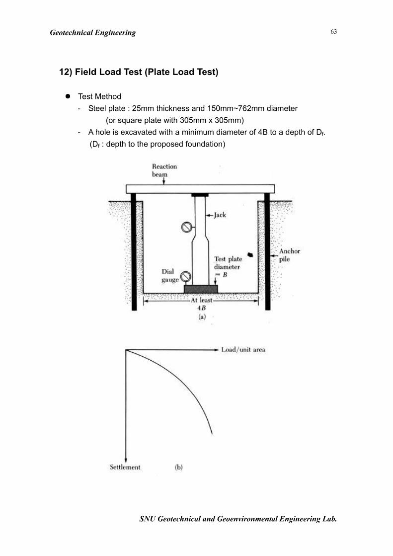
12) Field Load Test (Plate Load Test)
� Test Method
- Steel plate : 25mm thickness and 150mm~762mm diameter
(or square plate with 305mm x 305mm)
- A hole is excavated with a minimum diameter of 4B to a depth of Df.
(Df : depth to the proposed foundation)

Geotechnical Engineering
SNU Geotechnical and Geoenvironmental Engineering Lab.
64
� For tests in clay,
)()( puFu qq =
where,
)(Fuq = ultimate bearing capacity of the proposed foundation
)( puq = ultimate bearing capacity of the test plate
� For tests in sand,
p
FpuFuB
Bqq )()( =
where,
FB = width of the foundation
pB = width of the test plate
� Major drawback of plate load test
Effect of footing size difference
⇒
⇒

Geotechnical Engineering
SNU Geotechnical and Geoenvironmental Engineering Lab.
65
13) Tolerable Settlements
- Non-homogeneous subsoil conditions + wide variation of the load
carried by various shallow foundations.
�
�
- The parameters for definition of tolerable settlement
* TS = Total vertical displacement at point i
* TS∆
=
=
Differential settlement between i and j
)()( iTjT SS −
*∆ = Relative deflection
*ω = Tilt
* β = Angular distortion = ijT lS /∆
* L/∆ = Deflection ratio
- Criteria for tolerable settlement are determined based on types and
functions of structures.
ijl
l
)(iTS ω
∆ β
)( jTS

Geotechnical Engineering
SNU Geotechnical and Geoenvironmental Engineering Lab.
66
� Skempton and McDonald
- Maximum settlements, (max)TS
In sand 32mm
In clay 45mm
- Maximum differential settlements, (max)TS∆
Isolated foundations in sand 51mm
Isolated foundations in clay 76mm
Raft in sand 51~76mm
Raft in clay 76~127mm
- Maximum angular distortion 1/300
� Soviet Code of Practice
- Allowable deflection ratio is a function of L/H, the ratio of the length to
the height of a building.
Type of Building HL / L/∆
Multistory building and civil
dwelling
3≤ 0.0003 (for sand)
0.0004 (for clay)
5≥ 0.0005 (for sand)
0.0007 (for clay)
One-story mills 0.001 (for sand and clay)

Geotechnical Engineering
SNU Geotechnical and Geoenvironmental Engineering Lab.
67
� Bjerrum
Category of potential damage maxβ
Safe limit for flexible brick wall (L/H > 4)
Danger of structural damage to most buildings
Cracking of panel and brick walls
Visible tilting of high rigid buildings
First cracking of panel walls
Safe limit for no cracking of building
Danger to frames with diagonals
1/150
1/150
1/150
1/250
1/300
1/500
1/600
- Allowable deflection ratio is a function of L/H, the ratio of the length to
the height of a building.
� European Committee
Item Parameter Magnitude Comments
TS 25mm
50mm
Isolated shallow foundation
Raft foundation
TS∆ 5mm
10mm
20mm
Frames with rigid cladding
Frames with flexible cladding
Open frames
Limiting values
for serviceability
(European Committee
for Srandardization, 1994a)
β 1/500 -
TS 50 Isolated shallow foundation
TS∆ 20 Isolated shallow foundation
Maximum acceptable
foundation movement
(European Committee
for Srandardization, 1994b)
β ≈ 1/500 -

Geotechnical Engineering
SNU Geotechnical and Geoenvironmental Engineering Lab.
68
14) Mat Foundations
� When individual footing plan areas cover 50~75% of the plan area of the
structure, use a mat foundation.
� Types of mat foundations (based on rigidity of footing)
a) Flat plate
b) Flat plate thickened under columns
c) Beams and slabs
d) Flat plates with pedestals
e) Slab with basement walls as a part of the mat

Geotechnical Engineering
SNU Geotechnical and Geoenvironmental Engineering Lab.
69
� Points for design
� Bearing Capacity
- Bearing capacity can be obtained with the same formula for spread
footing.
idsqiqdqsqcicdcscu FFBFFFFqNFFFcNq γγγγ++= 2/1
- If embedded, the net applied load, nq
fdesignn Dqq γ−=
- So, for bearing capacity stability
nfu)net(all qFS/)Dq(q ≥−= γ
(or designuall qFSqq ≥= / )
Df
- Compensated foundation ;
No increase of the net
pressure on soil below a
mat foundation.
� 0=−= fdesignn Dqq γ
γ/designf qD = �
Effective on
reducing the
settlements.
qdesign

Geotechnical Engineering
SNU Geotechnical and Geoenvironmental Engineering Lab.
70
For NC clays
'p (log scale)
e∆ excavation
e e∆ e loading
(a) No compensating (b) Fully compensating
- Allowable bearing pressure using SPT tests (Bowles);
From Eq.(5.79),
)4.25/))(/(33.01()28.3
128.3(98.11)/( 22
)( efcornetall SBDB
BNmKNq +
+=
where eS =settlement, in mm.
For mat foundation, B is very large. => BB 28.3128.3 ≈+
)4.25/))(/(33.01(98.11)/( 2
)( efcornetall SBDNmKNq += ≤ )4.25/(93.15 ecor SN
- Based on 2 inch total settlement and conservatively assuming that
1))/(33.01( =+= BDF fd
cornetall NmkNq 96.23)/( 2
)( =
↓ po’(=pc’)
po’+∆p
p’(log scale)
po’-γDf po’

Geotechnical Engineering
SNU Geotechnical and Geoenvironmental Engineering Lab.
71
� Structural Design of Mat foundations
i) Conventional rigid method
- Bearing pressure : Uniform distribution for no eccentric loading
Varying linearly across the footing for eccentric
loading.
- Mat : Infinitely rigid and an inverted simply loaded two-way slab.
(Fig. 6.11b)
ii) Beam(slab) on elastic foundation (Winkler Foundation)
- Define the relationship between bearing pressure and settlement using
the modulus of subgrade reaction, )//,/( 2 mmkNqk δ=
- Then model the foundation soil as a bed of springs with a stiffness Sk .
(Fig. 6.12b)

Geotechnical Engineering
SNU Geotechnical and Geoenvironmental Engineering Lab.
72
* Case study
1. Bearing capacity failure (Coduto, p181, Collapse of the Fargo Grain
Elevator)
2. Field settlement observations for foundations (p.304, 5.5)

Geotechnical Engineering
SNU Geotechnical and Geoenvironmental Engineering Lab.
73

Geotechnical Engineering
SNU Geotechnical and Geoenvironmental Engineering Lab.
74

Geotechnical Engineering
SNU Geotechnical and Geoenvironmental Engineering Lab.
75