1:1 300W S-Band SSPA System Operations Manual · 2 212119 REV B Operations Manual, 300W S-Band...
112
1:1 300W S-Band SSPA System Operations Manual 212119 REV B ECO 17495 12/10/2013 Teledyne Paradise Datacom LLC Phone: (814) 238-3450 328 Innovation Blvd., Suite 100 Fax: (814) 238-3829 State College, PA 16803 USA Web: www.paradisedata.com Email: [email protected]
Transcript of 1:1 300W S-Band SSPA System Operations Manual · 2 212119 REV B Operations Manual, 300W S-Band...

1:1 300W S-Band SSPA System Operations Manual
212119 REV B ECO 17495 12/10/2013
Teledyne Paradise Datacom LLC Phone: (814) 238-3450 328 Innovation Blvd., Suite 100 Fax: (814) 238-3829 State College, PA 16803 USA Web: www.paradisedata.com Email: [email protected]
2 212119 REV B Operations Manual, 300W S-Band Redundant System
Teledyne Paradise Datacom LLC, a Teledyne Telecommunications company, is a single source for high power solid state amplifiers (SSPAs), Low Noise Amplifiers (LNAs), Block Up Converters (BUCs), and Modem products. Operating out of two primary locations, Witham, United Kingdom, and State College, PA, USA, Teledyne Paradise Datacom has a 20 year history of providing innovative solutions to enable satellite uplinks, battlefield communications, and cellular backhaul. Teledyne Paradise Datacom LLC Teledyne Paradise Datacom Ltd. 328 Innovation Blvd., Suite 100 2&3 The Matchyns, London Road, Rivenhall End State College, PA 16803 USA Witham, Essex CM8 3HA England (814) 238-3450 (switchboard) +44 (0) 1376 515636 (814) 238-3829 (fax) +44 (0) 1376 533764 (fax) Information in this document is subject to change without notice. The latest revision of this document may be downloaded from the company web site: http://www.paradisedata.com. Use and Disclosure of Data The information contained herein is classified as EAR99 under the U.S. Export Administration Regulations. Export, reexport or diversion contrary to U.S. law is prohibited. No part of this document may be reproduced or transmitted in any form without the written permission of Teledyne Paradise Datacom LLC. All rights are reserved in this document, which is property of Teledyne Paradise Datacom LLC. This document contains proprietary information and is supplied on the express condition that it may not be disclosed, reproduced or transmitted in any form without the written permission of Teledyne Paradise Datacom LLC. All other company names and product names in this document are property of the respective companies.
© 2013 Teledyne Paradise Datacom LLC Printed in the USA
Operations Manual, 300W S-Band Redundant System 212119 REV B 3
Table of Contents
Table of Contents .................................................................................................................. 3 Section 1: Introduction .......................................................................................................... 9
1.0 Introduction ............................................................................................................. 9 1.1 Scope and Purpose .............................................................................................. 10 1.2 Specifications ........................................................................................................ 11 1.3 Equipment Supplied .............................................................................................. 11 1.4 Inspection ............................................................................................................. 11 1.5 Shipment ............................................................................................................... 11 1.6 Safety Considerations ........................................................................................... 12
1.6.1 High Voltage Hazards ............................................................................. 12 1.6.2 High Current Hazards .............................................................................. 12 1.6.3 RF Transmission Hazards ....................................................................... 13 1.6.4 Electrical Discharge Hazards .................................................................. 13
Section 2: Component Description and Installation ......................................................... 15
2.0 Introduction ........................................................................................................... 15 2.1 3RU SSPA Chassis .............................................................................................. 15
2.1.1 3RU SSPA Front Panel Features ............................................................ 16 2.1.1.1 Fault Condition LEDs ................................................................. 16 2.1.1.2 Standby Select key ................................................................... 16 2.1.1.3 Front Panel Display ................................................................... 16 2.1.1.4 Navigation keys ......................................................................... 16 2.1.1.5 Main Menu key ......................................................................... 16 2.1.1.6 Local/Remote key ..................................................................... 17 2.1.1.7 Mute/Unmute key ..................................................................... 17 2.1.1.8 RF Input Sample Port (Optional) [N-type (F)] ............................ 17 2.1.1.9 Output Sample Port (N-type (F)) ................................................ 17 2.1.1.10 Removable Fan Assembly ....................................................... 17
2.1.2 SSPA Rear Panel Features ..................................................................... 18 2.1.2.1 DC Input with N+1 Redundant External Power Supply .............. 18 2.1.2.2 RF Input Port (J1) [Type N (f)] ................................................... 18 2.1.2.3 RF Output Port (J2) [Type N (f)] ................................................ 18 2.1.2.4 Switch Port (J3) [6-pin MS-type] ................................................ 19 2.1.2.5 Serial Main (J4) [DB9 (F)] .......................................................... 19 2.1.2.6 Serial Local (J5) [DB9 (M)] ........................................................ 20 2.1.2.7 Program Port (J6) [DB25 (M)] .................................................... 20 2.1.2.8 Parallel I/O (J7) [DB37 (F)] ........................................................ 20 2.1.2.8a Hardware Mute (Tx Enable)..................................................... 20 2.1.2.9 Link Port (J8) [DB9 (M)] ............................................................. 22 2.1.2.10 Ethernet Port (J9) [RJ45] ........................................................ 22 2.1.2.11 Power Supply M&C (J12) [DB9 (F)] ......................................... 22
2.2 1RU Power Supply Chassis .................................................................................. 23 2.2.1 Power Supply Insertion and Extraction.................................................... 23
2.3 1:1 Switch Assembly with RF Input Splitter and Dummy Load ............................. 24
4 212119 REV B Operations Manual, 300W S-Band Redundant System
2.4 Installation ............................................................................................................. 25 2.4.1 Install Power Supply Chassis .................................................................. 25 2.4.2 Install SSPA Chassis ............................................................................... 26 2.4.3 Install 1:1 Switch Assembly ..................................................................... 26 2.4.4 Connect RF Input to SSPAs .................................................................... 26 2.4.5 Connect SSPA RF Output to Coaxial Switch ........................................... 27 2.4.6 Connect Link Cable Between SSPAs ...................................................... 27 2.4.7 Connect Switch Cable Between Coaxial Switch and SSPAs ................... 28 2.4.8 Connecting Power Supply to System SSPAs .......................................... 28 2.4.9 Connect Power Supply Alarm Cable ....................................................... 28 2.4.10 Applying Prime Power to Power Supply Chassis ................................... 30 2.4.11 Connect RF Output ................................................................................ 30 2.4.12 Apply RF Input to System ...................................................................... 30
Section 3: Front Panel Operation ....................................................................................... 31
3.0 Introduction ........................................................................................................... 31 3.1 Configuring SSPA for 1:1 Redundancy ................................................................. 32
3.1.1 SSPA Redundant System Configuration ................................................ 32 3.1.2 Online / Standby Amplifier Selection ....................................................... 33 3.1.3 Auto versus Manual switching mode ....................................................... 34 3.1.4 Physically rotating transfer switch ............................................................ 34 3.1.5 Switchover Muting ................................................................................... 34 3.1.6 Adjusting System Gain ............................................................................ 35 3.1.7 Mute/Unmute via SSPA Front Panel ....................................................... 35
3.2 SSPA Menu Structure ........................................................................................... 36 3.2.1 System Information Sub-Menu ................................................................ 37
3.2.1.1 Sys Info Page 1 .......................................................................... 38 3.2.1.2 Sys Info Page 2 .......................................................................... 38 3.2.1.3 Sys Info Page 3 .......................................................................... 38 3.2.1.4 Sys Info Page 4 .......................................................................... 39 3.2.1.5 Sys Info Page 5 .......................................................................... 39 3.2.1.6 Sys Info Page 6 .......................................................................... 39 3.2.1.7 Sys Info Page 7 .......................................................................... 40 3.2.1.8 Sys Info Page 8 .......................................................................... 40 3.2.1.9 IP Info Page 1 ............................................................................ 40 3.2.1.10 IP Info Page 2 .......................................................................... 40 3.2.1.11 IP Info Page 3 .......................................................................... 41 3.2.1.12 IP Info Page 4 .......................................................................... 41 3.2.1.13 Firmware Info Page 1 ............................................................... 41 3.2.1.14 Firmware Info Page 2 (version 4.0) .......................................... 41 3.2.1.15 Firmware Info Pages 3, 4, 5 and 6 (version 4.0) ...................... 41 3.2.1.16 N+1 Master Info Page 1 ........................................................... 42 3.2.1.17 N+1 Slave Info Page ............................................................... 42 3.2.1.18 N+1 Master Info Page 2 ........................................................... 43 3.2.1.19 N+1 Master Info Page 3 ........................................................... 43
3.2.2 Communication Setup Sub-Menu ............................................................ 44 3.2.2.1 Protocol ...................................................................................... 44 3.2.2.2 Baud Rate .................................................................................. 44 3.2.2.3 System Address ......................................................................... 44
Operations Manual, 300W S-Band Redundant System 212119 REV B 5
3.2.2.4 Interface ..................................................................................... 45 3.2.2.5 IP Setup ..................................................................................... 45 3.2.2.6 More .......................................................................................... 45
3.2.3 Operation Setup Sub-Menu ..................................................................... 46 3.2.3.1 Info ............................................................................................ 46 3.2.3.2 Buzzer ....................................................................................... 46 3.2.3.3 Mute .......................................................................................... 46 3.2.3.4 Sys. Mode .................................................................................. 46 3.2.3.5 Attenuation ................................................................................ 46 3.2.3.6 RF Units ..................................................................................... 46
3.2.4 Fault Monitoring Setup Sub-Menu ........................................................... 47 3.2.4.1 BUC Fault .................................................................................. 47 3.2.4.2 Auxiliary Faults .......................................................................... 47 3.2.4.3 RF Switch Faults ....................................................................... 47 3.2.4.4 Fault Latch ................................................................................. 48 3.2.4.5 Low RF / Automatic Level Control ............................................. 48
3.2.5 Options Sub-menu .................................................................................. 49 3.2.5.1 Backup User Settings ................................................................ 49 3.2.5.2 Restore ...................................................................................... 49 3.2.5.3 Lamp Test .................................................................................. 49 3.2.5.4 Password ................................................................................... 49 3.2.5.5 Front Panel Fan Speed.............................................................. 50 3.2.5.6 Reset ......................................................................................... 50
3.2.6 Redundancy Sub-Menu ........................................................................... 50 3.2.6.1 Switching ................................................................................... 50 3.2.6.2 Standby Select .......................................................................... 50 3.2.6.3 Standby Mode ........................................................................... 50 3.2.6.4 Unit Status ................................................................................. 51 3.2.6.5 Priority Select ............................................................................ 51 3.2.6.6 N+1 system operation parameters ............................................. 51
3.2.6.6.1 N+1 Array size ............................................................. 51 3.2.6.6.2 N+1 Address ................................................................ 51 3.2.6.6.3 Auto Gain control ......................................................... 51 3.2.6.6.4 N+1 Info ....................................................................... 52
3.3 N+1 Operational Basics (two or more units) ......................................................... 53 3.3.1 Selecting the Master Unit ........................................................................ 53 3.3.2 Controlling system operation ................................................................... 54 3.3.3 N+1 Addressing ....................................................................................... 54 3.3.4 Adjust system gain .................................................................................. 54 3.3.5 N+1 Automatic gain control option .......................................................... 55 3.3.6 N+1 RF power measurements ................................................................ 55 3.3.7 N+1 Fault Detection ................................................................................ 55
3.4 Reflected Power Option ........................................................................................ 56 3.4.1 Reflected Power Alarm ............................................................................ 56
Section 4: Remote Control Interface .................................................................................. 57
4.0 Overview ............................................................................................................... 57 4.1 Remote Control - Parallel ..................................................................................... 58
4.1.1 Control Outputs ...................................................................................... 58

6 212119 REV B Operations Manual, 300W S-Band Redundant System
4.1.2 Control Inputs ......................................................................................... 59 4.2 Serial Communication Protocol ............................................................................. 60
4.2.1 Header Sub-Packet ................................................................................. 60 4.2.1.1 Frame Sync Word ...................................................................... 60 4.2.1.2 Destination Address ................................................................... 60 4.2.1.3 Source Address ......................................................................... 60
4.2.2 Data Packet ............................................................................................. 61 4.2.2.1 Protocol ID ................................................................................. 61 4.2.2.2 Request ID ................................................................................. 61 4.2.2.3 Command .................................................................................. 61 4.2.2.4 Data Tag .................................................................................... 62 4.2.2.5 Error Status / Data Address ....................................................... 62 4.2.2.6 Data Length ............................................................................... 63 4.2.2.7 Data Field .................................................................................. 63
4.2.3 Trailer Packet .......................................................................................... 64 4.2.3.1 Frame Check ............................................................................. 64
4.2.4 Timing issues ........................................................................................... 64 4.3 Access SSPA subsystem through Packet Wrapper technique .............................. 65 4.4 Example 1 Check SSPA settings .......................................................................... 72 4.5 Terminal Mode Serial Protocol for Paradise Datacom SSPA ................................ 74 4.6 Ethernet Interface .................................................................................................. 76
4.6.1 IPNet Interface ......................................................................................... 76 4.6.1.1 General Concept ........................................................................ 76 4.6.1.2 Setting IPNet interface ............................................................... 78 4.6.1.3 Using the Rack Mount Web Interface ........................................ 79
4.6.2 SNMP interface ....................................................................................... 81 4.6.2.1 Introduction ................................................................................ 81 4.6.2.2 SNMP MIB tree .......................................................................... 82 4.6.2.3 Description of MIB entities ......................................................... 83 4.6.2.4 Configuring RM SSPA unit to work with SNMP protocol ............ 84 4.6.2.5 Connecting to a MIB browser ..................................................... 89
Section 5: Troubleshooting ................................................................................................. 91
5.0 Troubleshooting Faults .......................................................................................... 91 5.0.1 Summary Fault ........................................................................................ 91 5.0.2 Voltage Fault ........................................................................................... 91 5.0.3 Temperature Fault ................................................................................... 91 5.0.4 Current Fault ............................................................................................ 92 5.0.5 Power Supply Fault ................................................................................. 92 5.0.6 Fan Fault ................................................................................................. 92 5.0.7 Low RF Fault ........................................................................................... 92
5.1 Modular SSPA Architecture ................................................................................... 93 5.1.1 Removable Fan Assembly ....................................................................... 93 5.1.1.1 Fan and Heatsink Maintenance ............................................................ 94 5.1.2 Removable Controller Card (rear panel) .................................................. 94 5.1.3 Firmware Upgrade Procedure ................................................................. 96
5.1.3.1 Required hardware .................................................................... 96 5.1.3.2 Download Firmware ................................................................... 96 5.1.3.3 Step-by Step procedure ............................................................. 97
Operations Manual, 300W S-Band Redundant System 212119 REV B 7
Appendix A: Ethernet Interface Quick Set-up ................................................................... 99 Appendix B: Proper 10/100 Base-T Ethernet Cable Wiring ............................................ 103 Appendix C: RM SSPA Control with Universal M&C Application .................................. 107 Appendix D: Documentation ............................................................................................ 111 Figures Figure 1-1: Outline Drawing, 300W S-Band 1:1 Redundant System, HPAS3300GTXB001 .... 9 Figure 2-1: 3RU SSPA Chassis Front Panel ......................................................................... 16 Figure 2-2: 3RU SSPA Chassis Rear Panel .......................................................................... 18 Figure 2-3: 1RU Power Supply Chassis ................................................................................ 23 Figure 2-4: 1RU Power Supply Module Insertion/Extraction .................................................. 23 Figure 2-5: 1:1 Switch Assembly ........................................................................................... 24 Figure 2-6: Cabinet Rail Dimensions and Slide Extender Positions ...................................... 25 Figure 2-7: Outline Drawing, Link Port Cable (L201794-1) .................................................... 27 Figure 2-8: Outline Drawing, Switch Cable (L211869-1) ........................................................ 28 Figure 2-9: Power Supply Alarm Cable (L211794-1) ............................................................. 29 Figure 2-10: 1RU Power Supply AC Line Inputs/Outputs ...................................................... 30 Figure 3-1: Simplified Block Diagram, 1:1 Redundant System .............................................. 31 Figure 3-2: “Unit 1” Indicator on SSPA Front Panel ............................................................... 33 Figure 3-3: System Mute/Unmute from SSPA Master Unit Front Panel ................................. 35 Figure 3-4: Front Panel Menu Structure ................................................................................ 36 Figure 3-5: System Information Menu Structure .................................................................... 37 Figure 3-6: Slave Unit Display ............................................................................................... 42 Figure 3-7: Communication Setup Sub-Menu ........................................................................ 44 Figure 3-8: Operation Setup Sub-Menu ................................................................................. 46 Figure 3-9: Fault Monitoring Setup Sub-Menu ....................................................................... 47 Figure 3-10: Options Sub-Menu ............................................................................................ 49 Figure 3-11: Redundancy Sub-Menu ..................................................................................... 50 Figure 3-12: N+1 Info menu ................................................................................................... 52 Figure 3-13: Front Panel Display, Master Unit (Online indicator illuminated) ......................... 53 Figure 3-14: Front Panel Display, Slave Unit (Online indicator dark) ..................................... 53 Figure 4-1: SSPA Remote Control Interface Stack ................................................................ 57 Figure 4-2: Parallel I/O Form C Relay ................................................................................... 58 Figure 4-3: Opto-Isolated Parallel I/O Input ........................................................................... 59 Figure 4-4: Basic Communication Packet .............................................................................. 60 Figure 4-5: Header Sub-Packet ............................................................................................. 60 Figure 4-6: Data Sub-Packet ................................................................................................. 61 Figure 4-7: Trailer Sub-Packet ............................................................................................... 64 Figure 4-8: Packet Wrapper technique .................................................................................. 65 Figure 4-9: Terminal Mode Session Example ........................................................................ 75 Figure 4-10: UDP Redirect Frame Example .......................................................................... 77 Figure 4-11: Initializing Web Interface ................................................................................... 79 Figure 4-12: GetIF Application Parameters Tab .................................................................... 89 Figure 4-13: Getif MBrowser window, with update data in output data box ........................... 89 Figure 4-14: Getif MBrowser window, setting settingValue.5 to a value of ‘1’ ........................ 90 Figure 5-1: Front panel Fault display ..................................................................................... 91 Figure 5-2: Unscrew thumb screws and slide the tray from chassis ...................................... 93 Figure 5-3: Unplug quick connector to fully remove fan tray .................................................. 93 Figure 5-4: Example of dust blocking heatsink fins ................................................................ 94

8 212119 REV B Operations Manual, 300W S-Band Redundant System
Figure 5-5: Heatsink fins cleared of debris ............................................................................. 95 Figure 5-6: Loosen the two retaining thumbscrews ............................................................... 95 Figure 5-7: Remove card to access programming connectors ............................................... 95 Figure 5-8: 3RU Rack Mount SSPAs have two module programming connectors ................ 97 Figure 5-9: Insert adapter tail into module programming connector ....................................... 97 Figure A-1: TCP/IP Properties Window.................................................................................. 99 Figure B-1: Modular Plug Crimping Tool .............................................................................. 103 Figure B-2: Transmission Line ............................................................................................. 103 Figure B-3: Ethernet Cable Pin-Outs ................................................................................... 104 Figure B-4: Ethernet Wire Color Code Standards ................................................................ 105 Figure B-5: Wiring Using 568A Color Codes ........................................................................ 105 Figure B-6: Wiring Using 568A and 568B Color Codes ....................................................... 105 Figure C-1: New Rack Mount SSPA Dialog Window ........................................................... 107 Figure C-2: SSPA Status Window ....................................................................................... 108 Figure C-3: SSPA Faults Window ........................................................................................ 108 Figure C-4: SSPA Settings Window ..................................................................................... 109 Figure C-5: IP Setup Window .............................................................................................. 109 Tables Table 2-1: Switch Port (J3) pin outs ....................................................................................... 19 Table 2-2: Serial Main Port (J4) pin outs ................................................................................ 19 Table 2-3: Parallel I/O Port (J7) ............................................................................................. 21 Table 2-4: Ethernet Port (J9) pin outs .................................................................................... 22 Table 2-5: Link Port (J8) Pin Outs .......................................................................................... 27 Table 4-1: Command Byte Values ......................................................................................... 61 Table 4-2: Data Tag Byte Values ........................................................................................... 62 Table 4-3: Error Status Byte Values ...................................................................................... 63 Table 4-4: Request Frame Structure ..................................................................................... 66 Table 4-5: Response Frame Structure ................................................................................... 66 Table 4-6: System Setting Details .......................................................................................... 67 Table 4-7: System Threshold Addressing Details (Read Only) .............................................. 69 Table 4-8: System Conditions Addressing Details ................................................................. 70 Table 4-9: ADC Data Addressing Details ............................................................................... 71 Table 4-10: OSI Model for RM SSPA Ethernet IP Interface ................................................... 77 Table 4-11: Detailed Settings ................................................................................................. 85 Table 4-12: Detailed Thresholds ............................................................................................ 87 Table 4-13: Detailed Conditions ............................................................................................. 88
Operations Manual, 300W S-Band Redundant System 212119 REV B 9
Section 1: Introduction
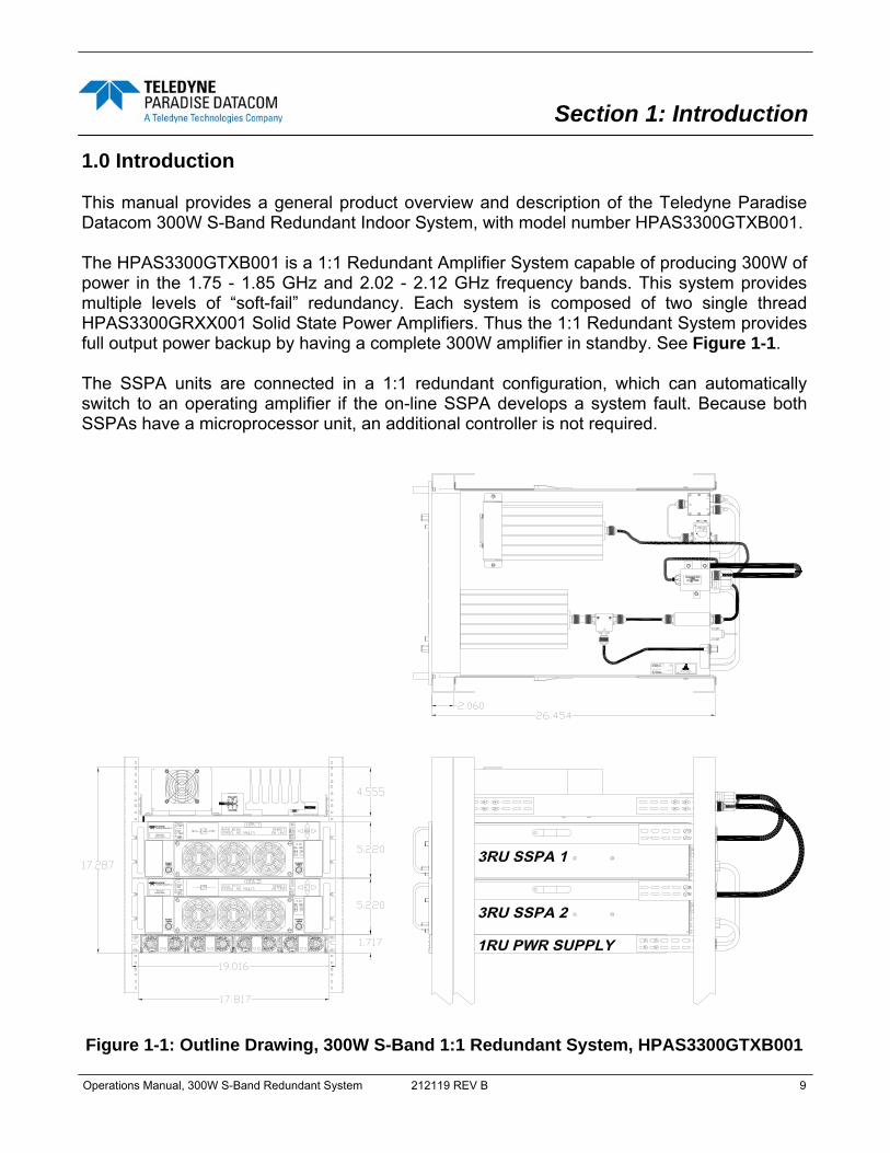
1.0 Introduction This manual provides a general product overview and description of the Teledyne Paradise Datacom 300W S-Band Redundant Indoor System, with model number HPAS3300GTXB001. The HPAS3300GTXB001 is a 1:1 Redundant Amplifier System capable of producing 300W of power in the 1.75 - 1.85 GHz and 2.02 - 2.12 GHz frequency bands. This system provides multiple levels of “soft-fail” redundancy. Each system is composed of two single thread HPAS3300GRXX001 Solid State Power Amplifiers. Thus the 1:1 Redundant System provides full output power backup by having a complete 300W amplifier in standby. See Figure 1-1. The SSPA units are connected in a 1:1 redundant configuration, which can automatically switch to an operating amplifier if the on-line SSPA develops a system fault. Because both SSPAs have a microprocessor unit, an additional controller is not required.
S/N: XXXXMODEL: XXXXXXXXXXXX
P/N: LXXXXXX-X
RF INPUTSAMPLERF INPUTSAMPLE
TELEDYNE
HPAS3-200200W S-BAND
RF INPUTSAMPLERF INPUTSAMPLE
TELEDYNE
HPAS3-200200W S-BAND
RF OUTPUTSAMPLE
RF OUTPUTSAMPLE
RF OUTPUTSAMPLE
RF OUTPUTSAMPLE
Figure 1-1: Outline Drawing, 300W S-Band 1:1 Redundant System, HPAS3300GTXB001

10 212119 REV B Operations Manual, 300W S-Band Redundant System
One of the amplifiers is designated as “on-line”; the other is designated as “standby”. The on-line SSPA receives the input RF signal and transmits an amplified RF signal to the RF load. The output of the standby SSPA is terminated at a dummy load. Two modes are available for the standby SSPA: “Hot” or “Cold” standby. An SSPA in “Hot” standby mode remains fully operational (the preferred method). An SSPA in “Cold” standby mode remains muted when off-line. This mode is only used where prime power conservation is critical. When the system is in “Auto” mode, if a summary fault develops in the on-line amplifier, its state will be sensed by the standby SSPA through the link cable. If the standby SSPA is in a non-faulted state, it will force the waveguide switch to reposition and put itself into the online state. Both SSPAs constantly monitor the waveguide switch position. The proper position for the online SSPA is determined by the “Unit Status” setting. If the selected SSPA is configured as “HPA1,” it will drive the RF switch to Position 1 to set itself to the on-line state. Selecting unit status to “HPA2” will configure that SSPA to drive the switch to Position 2 for the on-line state. In “Auto” mode, the online SSPA will make two attempts to force the switch to take proper po-sition before accepting its new state. The system is powered via a separate +28 VDC output, fully redundant power supply. The power supply is an N+1 redundant configuration, meaning that one extra power supply module is available than is required to operate the SSPA. A failure of a single power supply module will not take the amplifier off the air. In addition, the power supply modules are removable from the front panel while in operation. There is never a need to remove the power supply from the equipment bay. Weighing only 9 lbs. (4 kg) and occupying only 1 rack unit of cabinet space, the redundant power supply chassis is an excellent companion to the SSPA chassis. Power connection to the SSPA is via quick-snap connectors to the input power bulkhead at Port J10. Each power supply has a single phase, universal AC input ranging from 90-264 VAC, 47-63 Hz and is power factor corrected to > 0.95. The power supply is configured with four 1500W hot-swappable modules, each of which weigh approximately 5 lbs. (2.3 kg). 1.1 Scope and Purpose This manual provides the following:
• An overview of the 300W S-Band Redundant Indoor System, with Model Number HPAS3300GTXB001.
• General description and installation instructions for the 300W S-Band Redundant Indoor System, with Model Number HPAS3300GTXB001.
• Local and Remote operating instructions of the 300W S-Band Redundant Indoor System, with Model Number HPAS3300GTXB001.
• Maintenance and troubleshooting information.
Operations Manual, 300W S-Band Redundant System 212119 REV B 11
1.2 Specifications Refer to the specification sheet in Appendix C for complete specifications. 1.3 Equipment Supplied The following equipment is supplied with the system:
• Two (2) SSPA Chassis RM (3 RU high) • One (1) N+1 Redundant Power Supply • One (1) 1:1 Switch Plate Assembly • Two (2) pair of Rack Slides with B-308 extenders • Three (3) pairs of B-309 rack slide extenders • One (1) Power Supply Alarm Cable • One (1) Link Cable • One (1) Switch Cable • Four (4) coaxial cables labeled W2, W3, W4 and W5 • Operations Manual, 300W S-Band Redundant System [212119]
1.4 Inspection When the system is received, an initial inspection should be completed. First ensure that the shipping containers are not damaged. If a container is damaged, have a representative from the shipping company present when the container is opened. Perform a visual inspection of the equipment to make sure that all items on the packing list are enclosed. If any damage has occurred or if items are missing, contact: Teledyne Paradise Datacom LLC 328 Innovation Blvd., Suite 100 State College, PA 16803 USA Phone: +1 (814) 238-3450 Fax: +1 (814) 238-3829 1.5 Shipment To protect the system components during shipment, use high quality commercial packing methods. When possible, use the original shipping container and materials. Reliable commer-cial packing and shipping companies have facilities and materials to adequately repack the instrument.

12 212119 REV B Operations Manual, 300W S-Band Redundant System
1.6 Safety Considerations Potential safety hazards exist unless proper precautions are observed when working with this unit. To ensure safe operation, the user must follow the information, cautions and warnings provided in this manual as well as the warning labels placed on the unit itself. 1.6.1 High Voltage Hazards High Voltage, for the purpose of this section, is any voltage in excess of 30V. Voltages above this value can be hazardous and even lethal under certain circumstances. Care should be taken when working with devices that operate at high voltage.
• All probes and tools that contact the equipment should be properly insulated to prevent the operator from coming in contact with the voltage.
• The work area should be secure and free from non-essential items.
• Operators should never work alone on high voltage devices. There should always be another person present in the work area to assist in the event of an emergency.
• Operators should be familiar with procedures to employ in the event of an emergen-cy, i.e., remove all power, CPR, etc.
• An AC powered unit will have 115 VAC or 230 VAC entering through the AC power connector. Caution is required when working near this connector, the AC circuit breaker, or the internal power supply.
1.6.2 High Current Hazards Many high power devices are capable of producing large surges of current. This is true at all voltages, but needs to be emphasized for low voltage devices. Low voltage devices provide security from high voltage hazards, but also require higher current to provide the same power. High current can cause severe injury from burns and explosion. The following precautions should be taken on devices capable of discharging high current:
• Remove all conductive personal items (rings, watches, medals, etc.) • The work area should be secure and free of non-essential items. • Wear safety glasses and protective clothing. • Operators should never work alone on high risk devices. There should always be
another person present in the same area to assist in the event of an emergency. • Operators should be familiar with procedures to employ in the event of an emergen-
cy, i.e., remove all power, CPR, etc. Large DC currents are generated to operate the RF Module inside of the enclosure. Extreme caution is required when the enclosure is open and the amplifier is operating. Do not touch any of the connections on the RF module when the amplifier is operatig. Currents in excess of 60 Amperes may exist on any one connector.

Operations Manual, 300W S-Band Redundant System 212119 REV B 13
1.6.3 RF Transmission Hazards RF transmissions at high power levels may cause eyesight damage and skin burns. Pro-longed exposure to high levels of RF energy has been linked to a variety of health issues. Please use the following precautions with high levels of RF power.
• Always terminate the RF input and output connector prior to applying prime AC input power.
• Never look directly into the RF output waveguide • Maintain a suitable distance from the source of the
transmission such that the power density is below recommended guidelines in ANSI/IEEE C95.1. The power density specified in ANSI/IEEE C95.1-1992 is 10 mW/cm2. These requirements adhere to OSHA Standard 1910.97.
• When a safe distance is not practical, RF shielding should be used to achieve the recommended power density levels.
1.6.4 Electrical Discharge Hazards An electric spark can not only create ESD reliability problems, it can also cause serious safety hazards. The following precautions should be followed when there is a risk of electrical dis-charge:
• Follow all ESD guidelines • Remove all flammable material and solvents from the
area. • All probes and tools that contact the equipment should
be properly insulated to prevent electrical discharge. • The work area should be secure and free from non-
essential items. • Operators should never work alone on hazardous equipment. There should always
be another person present in the same work area to assist in the event of an emer-gency.
• Operators should be familiar with procedures to employ in the event of an emergen-cy, i.e., remove all power, CPR, etc.

14 212119 REV B Operations Manual, 300W S-Band Redundant System
THIS PAGE LEFT INTENTIONALLY BLANK

Operations Manual, 300W S-Band Redundant System 212119 REV B 15
Section 2: Component Description and Installation
2.0 Introduction This section offers a description of the components that comprise the 300W S-Band Redun-dant Indoor System, with model number HPAS3300GTXB001. These components include:
• (2) 300W S-Band 3RU SSPA Chassis, model number HPAS3300GRXX001 • (1) N+1 Power Supply Shelf with (4) 2500W Power Supply Modules • (1) 1:1 Switch Assembly with RF Input Splitter and Dummy Load
2.1 3RU SSPA Chassis The Teledyne Paradise Datacom Compact Rack Mount (CRM) Series SSPA Chassis was specially designed to accommodate applications where rack space is at a premium. At only 3RU in height and a depth of 24 inches (610 mm) the CRM Series SSPA Chassis is perfect for use in Satellite News Gathering or flyaway applications. A rich feature set has been maintained, despite the small size of the chassis. For field main-tainability, this chassis features:
• Front and rear panel removable fan trays • Front panel removable power supply modules • Rear panel removable controller card assembly • Front panel RF output sample port
This chassis includes a wide array of standard interfaces:
• Front Panel Local Interface and Status Indicators • RS232/RS485 (4-wire) Serial Communication (with either Windows-based M&C or
third-party M&C drivers available) • Ethernet Port (SNMP, UDP Serial Programming, Web Browser Interface) • Parallel I/O (Form C Contact Outputs, Opto Isolated Inputs)
The chassis’ microprocessor monitors various voltages, currents and temperatures within the unit for a full fault analysis. The user also may select additional faults related to the RF output level, an optional reflected RF power level and operating temperature. An internal attenuator allows up to 20.0 dB of attenuation to be applied to the RF signal. Temperature compensation limits the amplifier’s output response from varying significantly over the operating temperature. Also, the system contains input and output sample ports. See Appendix C for the specification sheet for the 300W S-Band SSPA Chassis.
16 212119 REV B Operations Manual, 300W S-Band Redundant System
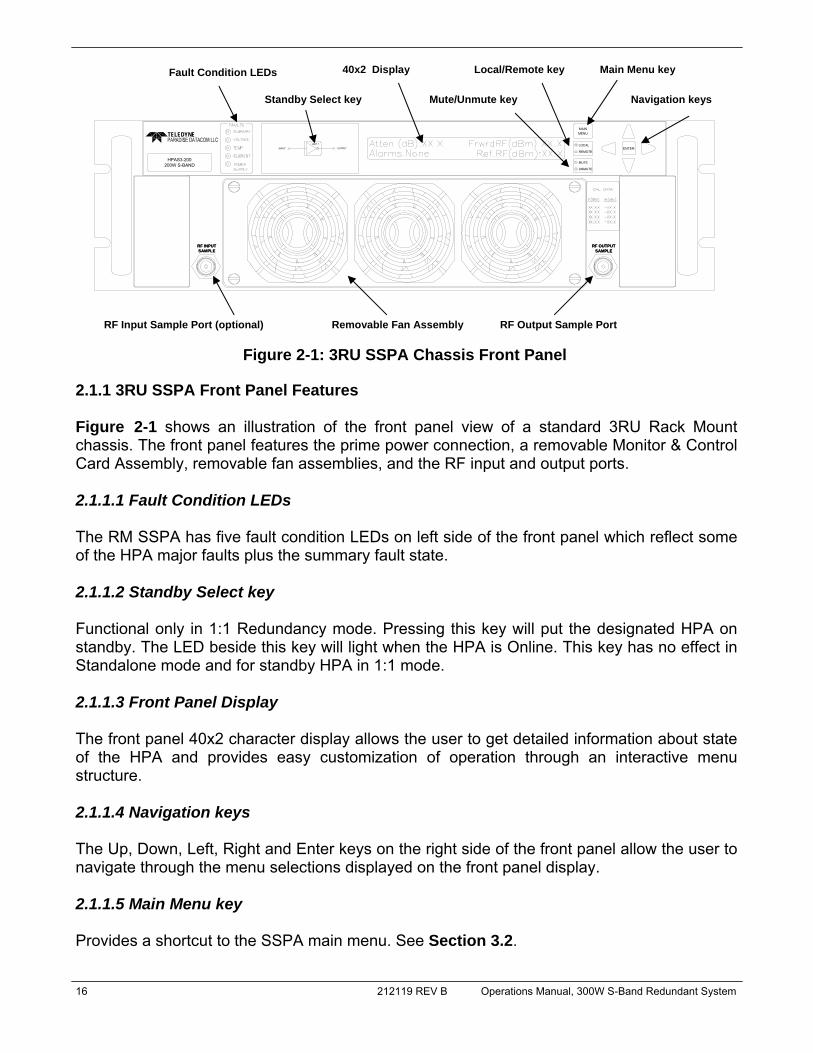
2.1.1 3RU SSPA Front Panel Features Figure 2-1 shows an illustration of the front panel view of a standard 3RU Rack Mount chassis. The front panel features the prime power connection, a removable Monitor & Control Card Assembly, removable fan assemblies, and the RF input and output ports. 2.1.1.1 Fault Condition LEDs The RM SSPA has five fault condition LEDs on left side of the front panel which reflect some of the HPA major faults plus the summary fault state. 2.1.1.2 Standby Select key Functional only in 1:1 Redundancy mode. Pressing this key will put the designated HPA on standby. The LED beside this key will light when the HPA is Online. This key has no effect in Standalone mode and for standby HPA in 1:1 mode. 2.1.1.3 Front Panel Display The front panel 40x2 character display allows the user to get detailed information about state of the HPA and provides easy customization of operation through an interactive menu structure. 2.1.1.4 Navigation keys The Up, Down, Left, Right and Enter keys on the right side of the front panel allow the user to navigate through the menu selections displayed on the front panel display. 2.1.1.5 Main Menu key Provides a shortcut to the SSPA main menu. See Section 3.2.
Figure 2-1: 3RU SSPA Chassis Front Panel
RF INPUTSAMPLERF INPUTSAMPLE
TELEDYNE
HPAS3-200200W S-BAND
UNIT 1
RF OUTPUTSAMPLE
RF OUTPUTSAMPLE
ENTERREMOTE
MUTE
UNMUTE
MAINMENU
LOCAL
Fault Condition LEDs
Standby Select key
40x2 Display Local/Remote key
Mute/Unmute key
Main Menu key
Navigation keys
RF Output Sample Port RF Input Sample Port (optional) Removable Fan Assembly

Operations Manual, 300W S-Band Redundant System 212119 REV B 17
2.1.1.6 Local/Remote key Allows the user to disable or enable the local control keypad console. If the SSPA is in "Remote Only" mode, the unit will not react to any keystrokes except the "Local/Remote" key. 2.1.1.7 Mute/Unmute key This key provides an easy way for the operator to change the Mute state of the SSPA. Muting the amplifier via the front panel requires 100 msec maximum (50 msec minimum). See Section 2.1.2.8a for a description of alternative muting methods. 2.1.1.8 RF Input Sample Port (Optional) [N-type (F)] An optional RF input sample port is located on the lower left corner of the SSPA front panel. This provides a -10 dBc coupled sample of the RF input signal. It is a N-type (f) connector. 2.1.1.9 Output Sample Port (N-type (F)) The Output RF Sample Port connector is located on the right lower corner of the HPA front Panel. This provides a -40 dBc coupled sample of the RF output signal. A calibration sticker is affixed above the N-type (f) connector. 2.1.1.10 Removable Fan Assembly The front panel fan assembly can be removed for maintenance. See Section 5.1.1 for details. The three-fan assembly operates at 20 VDC.
18 212119 REV B Operations Manual, 300W S-Band Redundant System
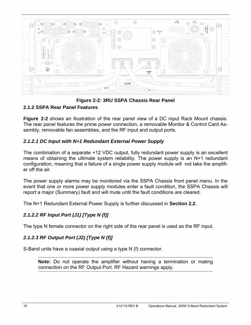
2.1.2 SSPA Rear Panel Features Figure 2-2 shows an illustration of the rear panel view of a DC input Rack Mount chassis. The rear panel features the prime power connection, a removable Monitor & Control Card As-sembly, removable fan assemblies, and the RF input and output ports. 2.1.2.1 DC Input with N+1 Redundant External Power Supply The combination of a separate +12 VDC output, fully redundant power supply is an excellent means of obtaining the ultimate system reliability. The power supply is an N+1 redundant configuration, meaning that a failure of a single power supply module will not take the amplifi-er off the air. The power supply alarms may be monitored via the SSPA Chassis front panel menu. In the event that one or more power supply modules enter a fault condition, the SSPA Chassis will report a major (Summary) fault and will mute until the fault conditions are cleared. The N+1 Redundant External Power Supply is further discussed in Section 2.2. 2.1.2.2 RF Input Port (J1) [Type N (f)] The type N female connector on the right side of the rear panel is used as the RF input. 2.1.2.3 RF Output Port (J2) [Type N (f)] S-Band units have a coaxial output using a type N (f) connector.
Note: Do not operate the amplifier without having a termination or mating connection on the RF Output Port. RF Hazard warnings apply.
+12VDCIN
J1J12
J2RF OUT
PS M&C RF IN
MAX
INP
UT
+15
dBm
+
-
ALARM
OUT
+12VDCIN
Figure 2-2: 3RU SSPA Chassis Rear Panel

Operations Manual, 300W S-Band Redundant System 212119 REV B 19
2.1.2.4 Switch Port (J3) [6-pin MS-type] A 6 pin Molex connector header with blind insertion system guides (mates with Molex P/N 39-01-2060) is used in a 1:1 Redundancy System to provide switching for the RF switch. Table 2-1 shows the pin outs for the Switch Port (J3).
Section 2.4.7 describes the Switch Cable used to connect two SSPAs with a switch in a 1:1 Redundant configuration. 2.1.2.5 Serial Main (J4) [DB9 (F)] A DB9 female connector serves as primary remote control interface connector. The interface is re-configurable through the front panel or can be used as a RS-232 or RS-485 interface (2 or 4 wires). The RS-485 TX and RX pairs must be twisted for maximum transmission distance. A user-configurable 120-ohm termination resistor is provided on the same connect-or. Table 2-2 shows the Serial Main (J4) connector pin outs.
Table 2-1: Switch Port (J3) pin outs Pin # Function / Description
1 +28V Switch Drive Output. 3 Amp over current protection.
2 Switch 1 Position 2 drive
3 Switch 1 Position 1 drive
4 +28V Switch Drive Output. 3 Amp over current protection.
5 Switch 2 Position 2 drive
6 Switch 2 Position 1 drive
Table 2-2: Serial Main Port (J4) pin outs Pin # Function / Description
1 RS-485 TX+ (HPA Transmit +)
2 RS-485 TX- (HPA Transmit -)/RS-232 TX
3 RS-485 RX- (HPA Receive -)/RS-232 RX
4 RS-485 RX+ (HPA Receive +)
5 GND
6 Service Request 1 Form C relay NC contact (Closed on HPA Summary Fault)
7 Service Request Common Form C relay common contact
8 Service Request 2 Form C relay NO contact (Opened on HPA Summary Fault)
9 120 ohm termination (must be connected to pin 4 to enable termination)

20 212119 REV B Operations Manual, 300W S-Band Redundant System
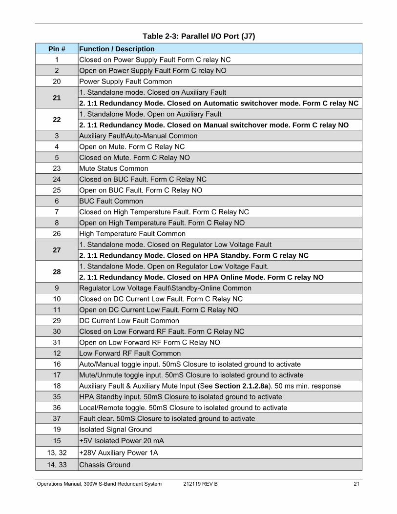
2.1.2.6 Serial Local (J5) [DB9 (M)] This DB9 male connector is used in advanced system integration and for system debugging purposes. Leave unconnected unless specified otherwise. 2.1.2.7 Program Port (J6) [DB25 (M)] A DB25 male connector is used to provide on field flash re-programmability for the HPA con-troller card. In order to reload controller board firmware, connect this port to a PC Parallel port through straight through cable. For a full description, see Sections 5.1.2 and 5.1.3. 2.1.2.8 Parallel I/O (J7) [DB37 (F)] A DB37 female type connector, the Parallel I/O port contains a series of contact closures for monitoring HPA faults as well as opto-isolated inputs for controlling some HPA functions. Inputs react on the closure to ground. The minimum closure time is 50mS. See Table 2-3 for a description of the pin-outs for this connector.
Note: When operating in 1:1 redundant mode, each SSPA unit will change some of its parallel I/O functions to alternative functions. See Table 2-3, pins 21, 22, 27 and 28.
2.1.2.8a Hardware Mute (Tx Enable) There are three ways to mute the amplifier via hardware input: 1) A 50 ms closure to ground on Port J7, Pin 17 to toggle between Mute/Unmute states; 2) Mute on a continuous closure to ground on Pin 18 of Port J7. Press the Main Menu key
on the front panel; select 4.Fault Setup and press the Enter key; select 2.Auxiliary Faults and press the Enter key; select 1.Action and press the Enter key; select 4.Alert+Mute and press the Enter key. Then select 4.Fault Setup and press the Enter key; select 2.Auxiliary Faults and press the Enter key; select 2.Fault Logic and press the Enter key; select 2.Fault on Low and press the Enter key. A continuous closure to ground on Port J7, Pin 18 will then mute the amplifier. See Section 3.2.4.2;
3) Mute on a continuous open to ground on Pin 18 of Port J7. Press the Main Menu key on the front panel; select 4.Fault Setup and press the Enter key; select 2.Auxiliary Faults and press the Enter key; select 1.Action and press the Enter key; select 4.Alert+Mute and press the Enter key. Then select 4.Fault Setup and press the Enter key; select 2.Auxiliary Faults and press the Enter key; select 2.Fault Logic and press the Enter key; select 2.Fault on High and press the Enter key. A continuous open to ground on Port J7, Pin 18 will then mute the amplifier. See Section 3.2.4.2.
Operations Manual, 300W S-Band Redundant System 212119 REV B 21
Table 2-3: Parallel I/O Port (J7) Pin # Function / Description
1 Closed on Power Supply Fault Form C relay NC 2 Open on Power Supply Fault Form C relay NO
20 Power Supply Fault Common
21 1. Standalone mode. Closed on Auxiliary Fault 2. 1:1 Redundancy Mode. Closed on Automatic switchover mode. Form C relay NC
22 1. Standalone Mode. Open on Auxiliary Fault 2. 1:1 Redundancy Mode. Closed on Manual switchover mode. Form C relay NO
3 Auxiliary Fault\Auto-Manual Common 4 Open on Mute. Form C Relay NC 5 Closed on Mute. Form C Relay NO
23 Mute Status Common 24 Closed on BUC Fault. Form C Relay NC 25 Open on BUC Fault. Form C Relay NO 6 BUC Fault Common 7 Closed on High Temperature Fault. Form C Relay NC 8 Open on High Temperature Fault. Form C Relay NO
26 High Temperature Fault Common
27 1. Standalone mode. Closed on Regulator Low Voltage Fault 2. 1:1 Redundancy Mode. Closed on HPA Standby. Form C relay NC
28 1. Standalone Mode. Open on Regulator Low Voltage Fault. 2. 1:1 Redundancy Mode. Closed on HPA Online Mode. Form C relay NO
9 Regulator Low Voltage Fault\Standby-Online Common 10 Closed on DC Current Low Fault. Form C Relay NC 11 Open on DC Current Low Fault. Form C Relay NO 29 DC Current Low Fault Common 30 Closed on Low Forward RF Fault. Form C Relay NC 31 Open on Low Forward RF Form C Relay NO 12 Low Forward RF Fault Common 16 Auto/Manual toggle input. 50mS Closure to isolated ground to activate 17 Mute/Unmute toggle input. 50mS Closure to isolated ground to activate 18 Auxiliary Fault & Auxiliary Mute Input (See Section 2.1.2.8a). 50 ms min. response 35 HPA Standby input. 50mS Closure to isolated ground to activate 36 Local/Remote toggle. 50mS Closure to isolated ground to activate 37 Fault clear. 50mS Closure to isolated ground to activate 19 Isolated Signal Ground 15 +5V Isolated Power 20 mA
13, 32 +28V Auxiliary Power 1A
14, 33 Chassis Ground

22 212119 REV B Operations Manual, 300W S-Band Redundant System
2.1.2.9 Link Port (J8) [DB9 (M)] The 9-pin male connector J8 Link Port is used to link a SSPA with other units in a redundant system in order to pass online/standby status information between them. In the 300W S-Band 1:1 Redundant System, a Link Cable is connected at this port between the two amplifiers. See Section 2.4.6. 2.1.2.10 Ethernet Port (J9) [RJ45] This is a RJ45 connector with integrated magnetics and LEDs. This port becomes the primary remote control interface when the Interface option is selected to “IPNet” as described in Section 4.6. This feature allows the user to connect the SSPA to a 10/100 Base-T Local Area Network and have full-featured Monitor & Control functions through a web interface. See Table 2-4 for Ethernet pin outs.
Note: IP address, Gateway address, Subnet mask, IP port and IP Lock address needs to be properly selected prior to first use (see Appendix A for details).
LED lamps on the connector indicate network status. A steady Green light indicates a valid Ethernet link; a flashing Yellow LED indicates data transfer activity (on either the Transmit and Receive paths). 2.1.2.11 Power Supply M&C (J12) [DB9 (F)] This is a DB9 female type connector which is used to communicate the alarm status of the connected power supply chassis. See Section 2.4.9.
Table 2-4: Ethernet Port (J9) pin outs
Pin # Function / Description 1 TX+ 2 TX- 3 RX+ 6 RX-
4,5,7,8 GND
Operations Manual, 300W S-Band Redundant System 212119 REV B 23
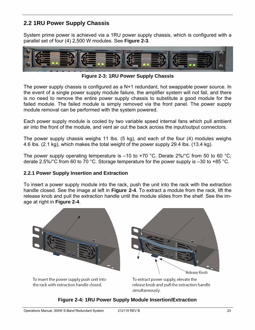
2.2 1RU Power Supply Chassis System prime power is achieved via a 1RU power supply chassis, which is configured with a parallel set of four (4) 2,500 W modules. See Figure 2-3.
The power supply chassis is configured as a N+1 redundant, hot swappable power source. In the event of a single power supply module failure, the amplifier system will not fail, and there is no need to remove the entire power supply chassis to substitute a good module for the failed module. The failed module is simply removed via the front panel. The power supply module removal can be performed with the system powered. Each power supply module is cooled by two variable speed internal fans which pull ambient air into the front of the module, and vent air out the back across the input/output connectors. The power supply chassis weighs 11 lbs. (5 kg), and each of the four (4) modules weighs 4.6 lbs. (2.1 kg), which makes the total weight of the power supply 29.4 lbs. (13.4 kg). The power supply operating temperature is –10 to +70 °C. Derate 2%/°C from 50 to 60 °C; derate 2.5%/°C from 60 to 70 °C. Storage temperature for the power supply is –30 to +85 °C. 2.2.1 Power Supply Insertion and Extraction To insert a power supply module into the rack, push the unit into the rack with the extraction handle closed. See the image at left in Figure 2-4. To extract a module from the rack, lift the release knob and pull the extraction handle until the module slides from the shelf. See the im-age at right in Figure 2-4.
Figure 2-4: 1RU Power Supply Module Insertion/Extraction
Figure 2-3: 1RU Power Supply Chassis

24 212119 REV B Operations Manual, 300W S-Band Redundant System
Caution: When inserting a power supply module into the rack, do not use unnecessary force. Slamming the power supply into the rack can damage the connectors on the rear of the supply and inside the rack.
It should be noted that if a power module is removed from the chassis during operation, it will trigger a power supply fault. You must wait 30 seconds before re-inserting the module or the fault will not clear. 2.3 1:1 Switch Assembly with RF Input Splitter and Dummy Load The switch assembly for the 300W S-Band 1:1 System consists of an RF Input Port with isolator, an RF Splitter, a coaxial switch, a transmit reject filter, a RF circulator, two 500W terminations and an RF Output Port. See Figure 2-5.
These components are mounted to a machined aluminum plate with mounting holes. The RF Input and RF Output connectors are all Type N (F) connectors. The cables which connect between the amplifiers and the switch assembly were all included with the system, and are detailed in Section 2.4.
Figure 2-5: 1:1 Switch Assembly
RF IN RF OUT TO SSPA 2 RF OUT TO SSPA 1 RF OUT FROM SSPA 1
RF OUT FROM SSPA 2
TERMINATION WITH FAN
RF SPLITTER
TERMINATION
ISOLATOR
TX REJECT FILTER
COAXIAL SWITCH
RF OUTPUT
Operations Manual, 300W S-Band Redundant System 212119 REV B 25
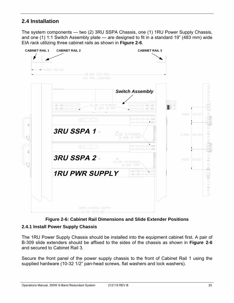
2.4 Installation The system components — two (2) 3RU SSPA Chassis, one (1) 1RU Power Supply Chassis, and one (1) 1:1 Switch Assembly plate — are designed to fit in a standard 19” (483 mm) wide EIA rack utilizing three cabinet rails as shown in Figure 2-6.
2.4.1 Install Power Supply Chassis The 1RU Power Supply Chassis should be installed into the equipment cabinet first. A pair of B-309 slide extenders should be affixed to the sides of the chassis as shown in Figure 2-6 and secured to Cabinet Rail 3. Secure the front panel of the power supply chassis to the front of Cabinet Rail 1 using the supplied hardware (10-32 1/2” pan-head screws, flat washers and lock washers).
Figure 2-6: Cabinet Rail Dimensions and Slide Extender Positions
CABINET RAIL 1 CABINET RAIL 2 CABINET RAIL 3
Switch Assembly

26 212119 REV B Operations Manual, 300W S-Band Redundant System
2.4.2 Install SSPA Chassis The SSPA Chassis are meant to be installed into the equipment cabinet using a pair of General Devices C-300 series rack slides and B-308 slide extenders. Use the dimensions shown in Figure 2-6 to determine the position of the rack slide installation. Install the slides into the equipment cabinet — to Cabinet Rail 2 and Cabinet Rail 3 — as described in the rack slide manufacturer’s documentation. To install the amplifiers into the cabinet, extend the rack slides from the equipment rack until they lock into place.
Note: At least two people are required to install the SSPA chassis into the equipment rack.
Warning! Always install equipment into the lower portion of the cabinet first.
This practice helps prevent the rack from tipping over. Each SSPA Chassis was shipped from the factory with a section of the rack slides affixed to the chassis side. Carefully slide the rack slides attached to the sides of the amplifier into the extended slides. Release the slide catches and gently push the amplifier into the cabinet until the front panel is flush with the installation rails (Cabinet Rail 1). Secure the amplifier to the installation rail at the SSPA front panel using quantity (10) 10-32x5/8” pan head screws, lock washers, flat washers and nylon washers provided. Tighten with a Phillips head screwdriver. 2.4.3 Install 1:1 Switch Assembly Refer to Figure 2-6. Attach the B-309 slide extenders to the sides of the 1:1 Switch Assembly plate with the hardware provided, such that the extenders may be used to install the assem-bly into the cabinet. The switch assembly should be mounted into the cabinet so that the connectors are at the cabinet rear. 2.4.4 Connect RF Input to SSPAs Locate the coaxial cables labeled W2 and W3. The cable ends are labeled so the installer may easily determine the connection points. Connect cable W2 between Port 1 of the RF Splitter and the RF Input Port (J1) of SSPA 1. Connect cable W3 between Port 2 of the RF Splitter and the RF Input Port (J1) of SSPA 2.

Operations Manual, 300W S-Band Redundant System 212119 REV B 27
2.4.5 Connect SSPA RF Output to Coaxial Switch Locate the coaxial cables labeled W4 and W5. The cable ends are labeled so the installer may easily determine the connection points. Connect cable W4 between the RF Output Port (J2) of SSPA 1 and Port J3 of the coaxial switch. Connect cable W5 between the RF Output Port (J2) of SSPA 2 and Port J2 of the coaxial switch. 2.4.6 Connect Link Cable Between SSPAs A Link Cable is connected between the SSPA’s Link Port (J8) connectors. This cable is used to pass online/standby status information between the SSPAs.
Warning! Do not remove the Link Cable while the system is in operation! The system will not operate properly.
Table 2-5 shows the pin outs of the Link Port (J8). Figure 2-7 shows an outline drawing of the Link Cable, part number L201794-1.
J8 Pin # Function / Description 6,7 Link Out (connect to “Link In” of Second SSPA; See Figure 2-5)
8,9 Link In (connect to “Link Out” of Second SSPA; See Figure 2-5)
1,2,3,4 Reserved, make no connection
5 Ground (Connect to same pin on Second SSPA; See Figure 2-5)
Table 2-5: Link Port (J8) Pin Outs
Figure 2-7: Outline Drawing, Link Port Cable (L201794-1)

28 212119 REV B Operations Manual, 300W S-Band Redundant System
2.4.7 Connect Switch Cable Between Coaxial Switch and SSPAs The SSPA redundant system controls a coaxial switch using the 6-pin rear panel connector J3. The switch is controlled by applying +28V to the common of the switch and pulsing either position to the ground. The system then verifies the position of the switch. The 6-pin Molex connector P/N 43810-002 is located on the SSPA rear panel at Port J3. This connector is used to interface with the RF switch. Figure 2-8 shows an outline drawing of the Switch Cable (part number L211869-1), which was connected to the switch at the factory. Connect Switch Cable connector P1 to SSPA 2 Port J3. Connect Switch Cable connector P2 to SSPA 1 Port J3.
2.4.8 Connecting Power Supply to System SSPAs The system was shipped with two pair of power cables which carry the DC power between the power supply DC Outputs and the SSPA DC Inputs. These cables are provided in two different lengths. Use the longer cables to connect to the SSPA farther away from the power supply chassis. Connect the M6 swivel connectors to the DC Output bus bars of the power supply. Connect the black cables to the –V terminals and the red cables to the +V terminals, as labeled on the cables. Power connection to the SSPA is via quick-snap power pole connectors to the SSPA input power bulkheads at the rear of the chassis. Make sure to connect the black cables to the –12VDC In ports and the red cables to the +12VDC In ports, as labeled on the cables. Connect the ring terminal of the yellow/green ground cable to the ground stud of each SSPA. Connect the other end to the cabinet’s earth ground.
Figure 2-8: Outline Drawing, Switch Cable (L211869-1)

Operations Manual, 300W S-Band Redundant System 212119 REV B 29
2.4.9 Connect Power Supply Alarm Cable Each power supply module has an alarm output which is monitored by the SSPA Chassis monitor and control system. This provides local and remote alarm reporting in the event of a power supply module failure. The power supply is connected to the SSPA via an alarm cable, part number L211794-1, supplied with the unit. This cable connects between the Alarm port of the power supply and the PS M&C Port (J12) of both SSPAs. In addition, this cable provides power to the cooling fan for the dummy load. See Figure 2-9.
The module alarm outputs are open-collector signals with a low level = fault logic level. Under normal operation the alarm outputs are in a high impedance state. In the event that a single power supply module enters a fault condition, the SSPA will report a minor fault. If more than one power supply module fails, the SSPA will report a major (Summary) fault and will mute until the fault conditions are cleared.
Figure 2-9: Power Supply Alarm Cable (L211794-1)
FROM TO
CONNECTOR TERMINAL CONNECTOR TERMINAL
P1 39 P2 1
P1 19 P2 2
P1 11 P4 1
P1 31 P4 2
P1 12 P4 3
P1 32 P4 4
P1 20 P4 5
P1 40 P3 5
P1 1 P1 21
P1 2 P1 22
P1 3 P1 23
P1 4 P1 24
P3 1 P4 1
P3 2 P4 2
P3 3 P4 3
P3 4 P4 4
P3 5 P4 5

30 212119 REV B Operations Manual, 300W S-Band Redundant System
2.4.10 Applying Prime Power to Power Supply Chassis In keeping with the redundant architecture of the power supply, there are individual AC inputs for each power supply module. Each power supply has a single phase, universal AC input ranging from 90-265 VAC, 47-63 Hz and is power factor corrected to 0.99. A separate AC in-put transformer could feed each AC input. Connect the first line/hot to L1, the second line or neutral to L2/N and the AC ground to GND. These terminal blocks will accept up to a maximum of 10 AWG wire, and should be torqued to 6 in-lbs. DC Outputs are in a bus bar configuration. See Figure 2-10.
In addition, connect a ground wire between the cabinet earth ground and the ground terminal in the center of the power supply chassis rear panel. 2.4.11 Connect RF Output Connect a mating connection or termination to the Type N (F) RF Output port on the switch assembly plate.
Warning! Do not operate the amplifier without having a termination or mating connection on the RF Output port. RF Hazard warnings apply.
2.4.12 Apply RF Input to System Apply an RF signal to the Type N (F) RF Input connector on the switch assembly plate.
Warning! Maximum input power is +15 dBm.
Figure 2-10: 1RU Power Supply AC Line Inputs/Outputs
+ - DC Outputs
+ - DC Outputs
Operations Manual, 300W S-Band Redundant System 212119 REV B 31
Section 3: Front Panel Operation
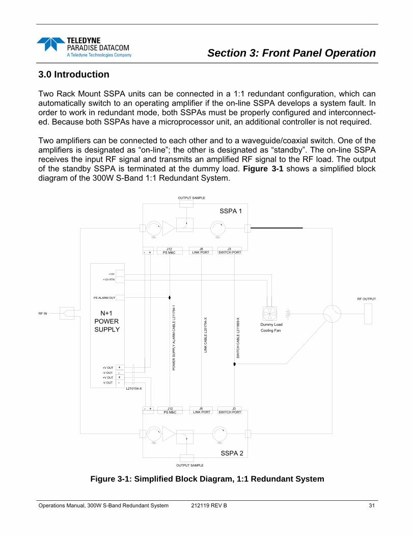
3.0 Introduction Two Rack Mount SSPA units can be connected in a 1:1 redundant configuration, which can automatically switch to an operating amplifier if the on-line SSPA develops a system fault. In order to work in redundant mode, both SSPAs must be properly configured and interconnect-ed. Because both SSPAs have a microprocessor unit, an additional controller is not required. Two amplifiers can be connected to each other and to a waveguide/coaxial switch. One of the amplifiers is designated as “on-line”; the other is designated as “standby”. The on-line SSPA receives the input RF signal and transmits an amplified RF signal to the RF load. The output of the standby SSPA is terminated at the dummy load. Figure 3-1 shows a simplified block diagram of the 300W S-Band 1:1 Redundant System.
J3SWITCH PORT
J8LINK PORT
OUTPUT SAMPLE
SSPA 1
SSPA 2
SWITCH PORTJ3
LINK PORTJ8
OUTPUT SAMPLE
LIN
K C
ABL
E L
2017
94-X
RF IN
PS M&CJ12
N+1POWER
+-
+- J12PS M&C
L210154-X
SW
ITC
H C
AB
LE L
2118
69-X
Dummy LoadCooling Fan
POW
ER
SU
PPLY
ALA
RM
CA
BLE
L21
1794
-1
RF OUTPUT
+-
+V OUT
-V OUT+-
+V OUT
-V OUT
PS ALARM OUT
+12V
+12V RTN
SUPPLY
Figure 3-1: Simplified Block Diagram, 1:1 Redundant System
32 212119 REV B Operations Manual, 300W S-Band Redundant System
When the system is in “Auto” mode, if a summary fault develops in the on-line amplifier, its state will be sensed by the standby SSPA through the link cable. If the standby SSPA is in a non-faulted state, it will force the waveguide switch to reposition and put itself into the online state. The process takes no more than 200 ms. Both SSPAs constantly monitor the waveguide switch position. The proper position for the online SSPA is determined by the “Unit Status” setting. If the selected SSPA is configured as “HPA1,” it will drive the RF switch to Position 1 to set itself to the on-line state. Selecting unit status to “HPA2” will configure that SSPA to drive the switch to Position 2 for the on-line state. In “Auto” mode, the online SSPA will make two attempts to force the waveguide switch to take proper position before accepting its new state. 3.1 Configuring SSPA for 1:1 Redundancy Two Teledyne Paradise Datacom Rack Mount SSPA units are used for a 1:1 redundant configuration. The units are connected to each other through a link cable, which allows the exchange of online/standby statuses between SSPAs. Both SSPA units are connected to the waveguide switch through the Switch Cable described in Section 2.4.7. This allows either amplifier to drive the switch to its proper position. Each unit must be configured with a unique identity. If one SSPA is configured as “HPA1”, the other should be configured as “HPA2”. Both SSPAs must be set to 1:1 Redundancy mode. 3.1.1 SSPA Redundant System Configuration The SSPAs were configured at the factory to work in 1:1 Redundant Mode. If the SSPAs need to be manually configured from the front panel to work in a 1:1 system, perform the following steps: Set SSPA1 to work in 1:1 mode
1. From the front panel of SSPA1, press the Main Menu key; 2. Select item 3.Operation and press the Enter key; 3. Select item 4.Sys.Mode and press the Enter key; 4. Select item 2.1:1 Mode and press the Enter key;
Set SSPA1 switching mode
1. From the front panel of SSPA1, press the Main Menu key; 2. Select item 6.Redund. and press the Enter key; 3. Select item 1.Switching and press the Enter key; 4. Select desired SSPA switching method (1.Auto or 2.Manual) and press the Enter
key. Set SSPA1 unit status
1. From SSPA front panel press the Main Menu key; 2. Select item 6.Redund. and press the Enter key; 3. Select item 4.Unit Status and press the Enter key; 4. Select item 1.HPA1 and press the Enter key.
Operations Manual, 300W S-Band Redundant System 212119 REV B 33
Set SSPA2 to work in 1:1 mode 1. From the front panel of SSPA2, press the Main Menu key; 2. Select item 3.Operation and press the Enter key; 3. Select item 4.Sys.Mode and press the Enter key; 4. Select item 2.1:1 Mode and press the Enter key;
Set SSPA2 switching mode
1. From the front panel of SSPA2, press the Main Menu key; 2. Select item 6.Redund. and press the Enter key; 3. Select item 1.Switching and press the Enter key; 4. Select desired SSPA switching method (1.Auto or 2.Manual) and press the Enter
key. Operator must use the same switching mode as selected for SSPA1. Set SSPA2 unit status
1. From SSPA2 front panel press the Main Menu key; 2. Select item 6.Redund. and press the Enter key; 3. Select item 4.Unit Status and press the Enter key; 4. Select item 1.HPA2 and press the Enter key.
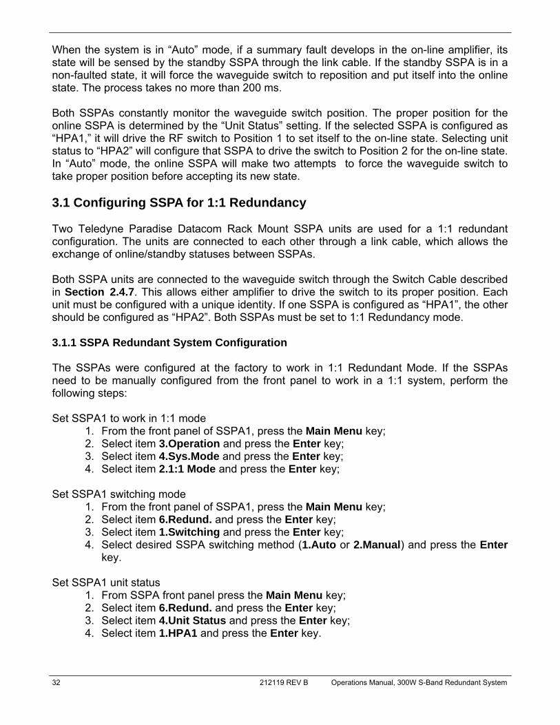
3.1.2 Online / Standby Amplifier Selection To determine the on-line state of a particular SSPA, check that the “Unit 1” button on the front panel keypad (See Figure 3-2) is illuminated. To put the SSPA in standby mode, press the “Unit 1” key and the light should go off. If the system is in “Auto” mode, the second SSPA will accept the on-line state only if there is no summary alarm.
The “Unit1” LED on the second SSPA will illuminate, indicting it is on-line and will rotate the switch to the correct position. If the second SSPA does not accept the on-line state, the first SSPA will revert to the on-line state after 1 second.
Note: Changing the on-line status of the amplifiers relies on a “give-away” process, wherein the active, on-line SSPA gives away its on-line status to the stand-by amplifier.
In manual mode, the standby SSPA will always accept the on-line state regardless of its own fault status. The user can verify the state of the waveguide switch by browsing to informative screen [3] on the front panel display. Item RFSW1 will indicate the state of the waveguide switch, as detected by the SSPA. If the switch position can not be detected, “Fault” will be dis-played.
Figure 3-2: “Unit 1” Indicator on SSPA Front Panel

34 212119 REV B Operations Manual, 300W S-Band Redundant System
3.1.3 Auto versus Manual switching mode Normal operation mode for a RM SSPA in 1:1 redundant configuration is “Auto”. This mode provides automatic SSPA fault detection and switchover to the operational SSPA. The system is also protected from operator errors; selecting a faulted SSPA is not allowed. In situations where system maintenance must be performed, “Manual” mode should be used. In “Manual” mode, the operator can select the on-line and standby SSPA by pressing the “Unit1” key. The system will not provide automatic switchover from a faulted SSPA, but will keep the selected SSPA online, regardless of its state.
Note: In order to function normally, both SSPAs must utilize the same switching mode.
3.1.4 Physically rotating transfer switch It is possible to physically rotate the shaft on the transfer switch to change the online and standby amplifiers positions. This can be done either in manual or automatic mode. When the switch is physically rotated in automatic mode the online SSPA will attempt to return the switch to its previous position. The SSPA will make two attempts to return the switch before accepting the new position. 3.1.5 Switchover Muting The following option was introduced into the SSPA control setup to overcome a problem with microwave arcing, which may potentially damage a switching component if the switching RF power exceeds 400 Watts. This particular problem becomes a critical issue if coaxial RF pass switches are used. In general, all Teledyne Paradise Datacom SSPAs are well protected against high reflected power conditions, which may take place during output microwave switchover. However, coax-ial switches will develop an internal electrical arc during switchover if the output power is sig-nificant. Such conditions will not lead to instant failure, but over time may diminish some criti-cal RF switch characteristics. If switchover muting is activated, the system’s ability to output RF power will be bonded to the switch position sensing circuitry. Such circuitry consists of the following components: SSPA electronic switch position detector; wiring harness between SSPA and RF switch; RF switch position sensors. Failure of any of these components will lead to a break in transmission. To enable switchover muting from the SSPA Front Panel:
1. Press the Main Menu key; 2. Select item 4.Flt.Setup and press the Enter key; 3. Select item 3.RFSw Flt. and press the Enter key; 4. Select item 3.SwitchMute and press the Enter key.

Operations Manual, 300W S-Band Redundant System 212119 REV B 35
3.1.6 Adjusting System Gain To adjust the gain of the system, press the Main Menu key of the online unit, select 3.Operation and press the Enter key; select 5.Attenuation and press the Enter key. Enter the desired value (between 0 and 20.0 dB) by using the Left Arrow [◄] and Right Arrow [►] keys to adjust the ones place and the Up Arrow [▲] and Down Arrow [▼] keys to adjust the tens place. Alternately, from any of the System Information menus described in Section 3.2, press either the Left Arrow [◄] or Right Arrow [►] keys. Enter the desired value (between 0 and 20.0 dB) by using the Left Arrow [◄] and Right Arrow [►] keys to adjust the ones place and the Up Arrow [▲] and Down Arrow [▼] keys to adjust the tens place. 3.1.7 Mute/Unmute via SSPA Front Panel To switch the mute condition of the amplifier from the front panel, locate the system’s online amplifier and press the Mute/Unmute key on the front panel. See Figure 3-3.
Muting SSPA 1 will not automatically mute SSPA 2. However, if SSPA 2 is the stand-by unit , and SSPA 1 experiences a fault condition, the system (in Auto Switching mode) will switch SSPA 2 to the online unit and will automatically unmute the unit. Alternately, the user may perform the following on the online amplifier’s front panel:
1. Press the Local/Remote key so that the LED next to Local is illuminated. 2. Press the Main Menu key; 3. Select 3.Operation and press the Enter key; 4. Select 3.Mute and press the Enter key; 5. Select 1.Mute On and press the Enter key to Mute the amplifier; 6. Select 2.Mute Off and press the Enter key to Unmute the amplifier.
Figure 3-3: System Mute/Unmute from SSPA Master Unit Front Panel

36 212119 REV B Operations Manual, 300W S-Band Redundant System
3.2 SSPA Menu Structure Figure 3-4 shows the Front Panel Menu Structure hierarchy. There are six main levels of menu selections. 1. Sys.Info - System Information menu sublevel (See Section 3.2.1) 2. Com.Setup - Serial Communication related settings (See Section 3.2.2) 3. Operation Setup - System operation related settings (See Section 3.2.3) 4. Fault Monitoring Setup - Fault handling settings (See Section 3.2.4) 5. Options - Backup/restore and password settings (See Section 3.2.5) 6. Redundancy - Switching and standby settings (See Section 3.2.6)
Main Menu navigation is provided by the Arrow keys [▲, ▼, ◄, ►] and Enter key on the front panel keypad. Item selection is shown in the bottom right corner of the VFD display. All selectable items have a sequential number. The user can increment or decrement the selected item number by using Left Arrow [◄] and Right Arrow [►] keys. Selection is final-ized when the user presses the “Enter” button. Pressing the “Main Menu” button brings the menu level to the Main Menu page from any stage of the menu selection. Some items within the menu structure have alternative methods for value selection. When this type of selection is specified, the selection keys are: the Up Arrow [▲] and Down Arrow [▼] keys are used to select numbers in x10 increments and Left Arrow [◄] and Right Arrow [►] keys for x1 increments. Selection is always specified by special notation on the far right hand side of the VFD.
Note: When the "Fault Latch" option is selected, pressing the Enter key will clear all system faults under this mode. To activate this option, press the Main Menu key, select 4.Flt. Setup and press the Enter key; select 4.Flt.Latch and press the Enter key; select 1.Enable and press the Enter key.
Figure 3-4: Front Panel Menu Structure
2.Com Setup1.Sys Info 3.Operation 4.Flt. Setup 5.Options
Main Menu
6.Redundancy
To Sys Info Page 1

Operations Manual, 300W S-Band Redundant System 212119 REV B 37
3.2.1 System Information Sub-Menu The informative sublevel menu structure contains several pages, shown in Figure 3-5. The user can also browse among these pages by pressing the Enter key on the keypad. Note that this function will not work if the "Fault Latch" option is selected. Pressing the Enter key will clear all system faults under this mode.
Figure 3-5: System Information Menu Structure
IP Setup Menus
IPAddr:XXX.XXX.XXX.XXX MAC:XXXXXXXXXXSubnet:XXX.XXX.XXX.XXX Port:XXXXX
Gateway:XXX.XXX.XXX.XXXLockIP:XXX.XXX.XXX.XXX
CommunityGet:XXXXXXXXXXXXXXXXXXXXXCommunitySet:XXXXXXXXXXXXXXXXXXXXX
1.IPInfo
SSPA Firmware Info
ParadiseDatacom Digicore XM128-Version X.XX (XX) Built YY, MMM DD
SSPAID:XXXXXXXXXXXXXXXXXXXXUserInfo:XXXXXXXXXXXXXXXXXXXX
Firmware:XXXXXXXXXX Module1ID:XXXXXXXXXXXXXXXXXXXXXX
1.Info
Firmware:XXXXXXXXXX Module2ID:XXXXXXXXXXXXXXXXXXXXXX
Firmware:XXXXXXXXXX Module3ID:XXXXXXXXXXXXXXXXXXXXXX
Firmware:XXXXXXXXXX Module4ID:XXXXXXXXXXXXXXXXXXXXXX
MainMenu 3.Operation
MainMenu 3.Operation 5.IPSetup
Web Password:XXXXXXXXXXXXXXXXXXXXX
N+1 Slave UnitUnit operation under system control
N+1 Slave unit system info
Slave UnitsMaster Unit only
PS:XXXXXX LowRF:XXXXXX Fan:XXXXXXAUX:XXXXXX VSWR:XXXXXX BUC:XXXXXX
RFSW1:XXXXXX State:XXXXXX Prior:XXXXRFSW2:XXXXXX Mute:XXXXXX PolSel:XXXX
Prtcl:XXXXXX Intrfc:XXXXX Buzzer:XXXBaud:XXXXX Addrs.:XXX Latch:XXX
Mode:XXXXXXX Ctrl:XXXXXX Unit:XXXXStby:XXXX Switch:XXXXX FSpeed:XXX
PS1(V):XX.X Boost1(V):XX.X DC(A):XX.XPS2(V):XX.X Boost2(V):XX.X
Regulator:XXXXXX Temperature:XXXXXXDCCurrent:XXXXXX Temp.(C):XXX
Module1:XXXXXX Module3:XXXXXXModule2:XXXXXX Module4:XXXXXX
Atten.(dB):XX.X FrwrdRF(dBm):XX.XAlarms:XXXXXX Ref.RF(dBm):XX.X
System Info Menus
1.Sys.Info
MainMenu
Non N+1 Units
Atten.(dB):XX.X SysRFOut(dBm):XX.XAutoGain(dB):XX.X Ref.RF(dBm):XX.X
N+1 Arr.Size:XXX N+1 Alarms:XXXXXXN+1 Address:XXX N+1 State:XXXXXX
N+1 Master unit system info
Cabinet Temp(C):XXX Cabinet Fan:XXXXXX

38 212119 REV B Operations Manual, 300W S-Band Redundant System
3.2.1.1 Sys Info Page 1 This is the HPA main status information page. The page shows:
• HPA attenuation measured in dB ( Atten. (dB): XX.X) with accuracy of 0.1dB; • Forward RF Power, measured in either dBm with resolution of 0.1dBm, or Watts
with a resolution of 0.1 Watts • Alarms presence, "FAULT!" or "None" will be displayed depending on the state of
HPA; • Reflected RF Power, measured in either dB with resolution of 0.1dBm, or Watts
with a resolution of 0.1 Watts. Displays “N/A” if unavailable. 3.2.1.2 Sys Info Page 2 This page shows a variety of alarm states which may be present within the HPA. Fault values could be "Fault", "Normal" and "N/A"
• PS - power supply alarm, displays "Normal" if HPA power supplies are normally operational and "Fault" if one or more power supplies failed.
• LowRF - low RF fault; • Fan - cooling system failures; • Aux. - Auxiliary fault condition; • VSWR - High Reflected power fault; • BUC - Block Up converter fault.
If the fault condition doesn't apply to the HPA configuration it will display "N/A" for "Not Availa-ble". 3.2.1.3 Sys Info Page 3 This page displays miscellaneous information related to the redundancy operation and the HPA mute status.
• RFSW1 - state of RF switch 1, possible values - "Pos1" Pos2" "N/A", "Fault"; • RFSW2 - state of RF switch 2, possible values - "Pos1" Pos2" "N/A", "Fault"; • State - HPA online state, possible values "Online", "Standby"; • Mute - HPA mute state, possible values "Clear", "Set"; • Prior - Priority polarization select (1:2 Mode Only); • PolSel - Current Polarization output (1:2 Mode Only)
Operations Manual, 300W S-Band Redundant System 212119 REV B 39
3.2.1.4 Sys Info Page 4 This page displays various HPA settings:
• Prtcl. - current HPA remote control protocol. The value can be set to "Terminal", if terminal mode protocol is currently active and "Normal" for string I/O type protocol.
• Baud - selected baud rate for remote control serial port. Selection: "2400", "4800", "9600", "19200", "38400";
• Intrfc. - selected serial port interface. Selection: "RS232", "RS485". • Addrs. - HPA remote control network address. Value could be in range from 0 to
254. Note: address 255 is reserved for global calls and shouldn't be used for an individual unit’s addressing.
• Buzzer - Audible alarm availability. "Dis" if alarm disabled and "Enb" if enabled. • Latch - Fault latch option selection. "Dis," indicates disabled option and "Enb" if en-
abled. 3.2.1.5 Sys Info Page 5 Page 5 shows settings related to the HPA 1:1 Redundant System operation.
• Mode - indicates HPA operational mode. Value can be set to "1:1" for 1:1 redun-dancy mode and "Stdaln" for stand alone mode;
• Stby. - shows HPA standby state selection. "Hot" for hot standby operation (HPA retains unmuted state during standby period) and "Cold" for cold standby (HPA always mutes itself in standby mode and unmutes when switched back on-line).
• Ctrl. - shows HPA control style. "Local" - both local and remote control are support-ed and "Remote" when only remote control provided (keypad locked);
• Switch - indicates switching style. "Auto" for automatic fault tracking/switching and "Manual" if redundancy switching is provided by the operator.
• Unit - redundancy topological factor. "HPA1" for HPA connected to the RF switch port 1 or 4 (Online Position 1 of the RF switch). "HPA2" for HPA connected to the RF switch port 2 or 3 (Online Position2 of the RF switch).
3.2.1.6 Sys Info Page 6 This page shows the status of the HPA’s internal power supplies
• PS1(V) - main power supply 1 output voltage with resolution of 0.1V. Normal output voltage should be in range of 11 to 13 V.
• PS2(V) - main power supply 2 output voltage. • Boost1(V) - booster power supply 1 output voltage with resolution of 0.1V. Normal
range 24 to 30 V (typical 28V); • Boost2(V) - booster power supply 2 output voltage. • DC (A) - total DC current draw by RF modules from main power supply. Value var-
ies depending on the power level of the HPA. If the HPA is muted, current normally drops to within the 0 to 5 A range.

40 212119 REV B Operations Manual, 300W S-Band Redundant System
3.2.1.7 Sys Info Page 7 This page shows RF module related faults and conditions.
• Regulator - RF module regulator low voltage fault. Values - "Fault" or "Normal"; • DC Current - low DC current fault. Values -"Fault" or "Normal"; • Temperature - high temperature fault. Values - "Fault" or "Normal"; • Temp.(C) - internal RF module plate temperature in Celsius.
3.2.1.8 Sys Info Page 8 This page shows individual RF module states in multi-module HPA. If a particular module does not exist in the HPA configuration, the value shows "N/A" (not available). Each value represents summary fault state of the individual RF module, which in-cludes Voltage, Current and Temperature state as well as quality of data connection with module. If the HPA controller card can not reliably communicate with an SSPA module; that module will be declared faulted. This type of fault will not affect HPA overall summary fault state, be-cause the controller card has the ability to track RF module faults independently. 3.2.1.9 IP Info Page 1 This page is available through the Comm. Setup menu, and shows SSPA settings related to the IP interface.
• IP Address – IP address of the SSPA. Consult your network administrator to set this address according to your LAN configuration.
• MAC – Medium Access Control address of the SSPA Ethernet controller. This ad-dress is factory preset.
• Subnet – IP subnet mask of the SSPA. Consult your network administrator to set this address.
• IPPort – IP port value for the SSPA. This address is valid only when IPNet protocol is selected. The port value should not be selected outside the existing services range to avoid access conflict on the M&C PC end.
3.2.1.10 IP Info Page 2 This page shows SSPA settings related to the IP interface.
• Gateway – IP Gateway address. This address is used only if access to the SSPA is provided from an outside LAN. If no such access is required, the address must be set to 0.0.0.0
• LockIP – This address is used to increase the security measure for the IPNet proto-col. The SSPA will answer a request which comes only from a specified IP address. Set this address value to 0.0.0.0 or 255.255.255.255 to disable this feature.

Operations Manual, 300W S-Band Redundant System 212119 REV B 41
3.2.1.11 IP Info Page 3 This page shows SSPA settings related to the IP interface.
• CommunityGet – Security string used in SNMP protocol for Get type requests. Set this value to match the value specified in the NMS or MIB browser. Maximum string length is 20 alpha-numeric characters. The string allows read operation for the RM SSPA SNMP agent.
• CommunitySet – Security string used in SNMP protocol for Set type requests. Set this value to match the value specified in the NMS or MIB browser. For security rea-sons this string must be different than the Community Get string. The maximum string length is 20 alpha-numeric characters. The string allows write operation for the RM SSPA SNMP agent.
Community strings are essentially passwords. The user should use the same rules for select-ing them as for any other passwords: no dictionary words, spouse names, etc. An alphanu-meric string with mixed upper- and lower-case letters is generally a good idea. 3.2.1.12 IP Info Page 4 This page indicates the selected password for the web page interface. A blank space indi-cates that the web interface will not require a password protected login. 3.2.1.13 Firmware Info Page 1 This page is available through the Operation Setup menu, and provides information about the SSPA MCU firmware revision level. 3.2.1.14 Firmware Info Page 2 (version 4.0) This page provides additional SSPA information.
• SSPA ID – SSPA unique serial and model number. • UserInfo – User information string, which could be set over SNMP protocol (see
SNMP MIB info for details) 3.2.1.15 Firmware Info Pages 3, 4, 5 and 6 (version 4.0) These pages contain information about the firmware revision level and unique ID of each RF module. A SSPA may contain 1 to 4 RF modules. Pages will remain blank if a particular mod-ule is not installed.

42 212119 REV B Operations Manual, 300W S-Band Redundant System
3.2.1.16 N+1 Master Info Page 1 This page can only be viewed when the SSPA unit is configured as the N+1 Master unit. The page also becomes the default startup page for the Master SSPA . Several parameters related to N+1 System operational parameters are displayed:
• Atten.(dB) - System level attenuation. In the case when the N+1 Auto Gain option is turned on, this attenuation level may differ from an individual SSPA attenuation lev-el;
• AutoGain(dB) or SSPAGain(dB) - Displays the estimated system wide linear gain. Actual SSPA gain may differ if the unit has reached its saturated power level or malfunctions (see Section 3.3.5);
• SysRFOut - Indicates system forward RF output power detected at the output flange of the final phase combined structure. This value can be displayed in dBm or Watts, depending on the RF Unit setting. If the RF power detector unit is not acces-sible for any reason, the value shown will be “N/A”.
Note: If detected power falls below lowest detectable threshold it will read 0.00. In reality, RF output power may differ from the displayed value. Consult your system datasheet on RF detector dynamic range specifications!
• Ref.RF - Indicates system reflected RF power. This value can be displayed in dBm
or Watts, depending on the RF Unit setting. If the RF power detector unit is not ac-cessible for any reason, the value shown will be “N/A”.
Note: If reflected power falls below lowest detectable threshold it will read 0.00. In reality, RF output power may differ from the displayed value. Consult your system datasheet on RF detector dynamic range specifications!
3.2.1.17 N+1 Slave Info Page Figure 3-6 shows the display for all Slave units in the system.
This page can only be viewed when a SSPA unit is assigned as a N+1 Slave unit. All normal Info pages pertaining to individual SSPA operation parameters are accessible on subsequent menu levels. This page becomes the default page for N+1 slave unit.
Figure 3-6: Slave Unit Display

Operations Manual, 300W S-Band Redundant System 212119 REV B 43
3.2.1.18 N+1 Master Info Page 2 This page displays additional N+1 system operation data, and can be accessed by pressing the Up Arrow (▲) key from the N+1 Master Info Page 1. This page is only accessible from the N+1 Master unit.
• N+1 Arr.Size - Displays the N+1 array size. Valid sizes: 2, 4, 8 or 16 units. • N+1 Address - Displays the master unit N+1 priority address; • N+1 Alarms - Displays the number of detected SSPA unit alarms present in the
system. • N+1 State - Displays the current N+1 fault state. If the Master unit detects no more
than one (1) SSPA chassis alarm, the N+1 state will be displayed as “Normal”; otherwise “Fault”.
3.2.1.19 N+1 Master Info Page 3 This page displays information related to N+1 system operation, and can be accessed by pressing the Up Arrow (▲) key twice from the N+1 Master Info Page 1. This page is only accessible from the N+1 Master unit.
• Cabinet Temp(C) - Displays the temperature within the system cabinet. • Cabinet Fan - Displays the fault state of the cabinet exhaust impellers. Possible
states are: Normal, Fault or N/A.

44 212119 REV B Operations Manual, 300W S-Band Redundant System
3.2.2 Communication Setup Sub-Menu This menu, shown in Figure 3-7, allows the user to select the communication parameters be-tween the SSPA and any remote monitor and control station. 3.2.2.1 Protocol Allows the user to select the serial protocol. Available communication protocols include: a) Normal (as described in Section 4) b) Terminal (as described in Section 4.5) 3.2.2.2 Baud Rate Selects the desired baud rate for serial communication. Available baud rates include 2400, 4800, 9600, 19200 and 38400. The factory default Baud Rate is 9600. 3.2.2.3 System Address Sets the network address of the controller if used on a RS-485 network. Choose 1-255. The factory default address is 0.
2.Com Setup
3.Sys Addr
1.2400
1.RS232
3.Subnet
1.Community Get
1.Sys Info
2.Baud Rate
2.Terminal 1 .. 255
2.LocalIP
3.Operation
4.Interface
2.4800
2.RS485
4.Gateway
2.Community Set
4.Flt. Setup
5.IP Setup
3.9600
3.IPNet
5.LocalPort
3.Lock IP
5.Options
4.19200
4.SNMP
6.More
1.Protocol
1.Normal
5.38400
1.IPInfo
Main Menu
6.Redundancy
To IP Info Page 4.Web Password
Figure 3-7: Communication Setup Sub-Menu

Operations Manual, 300W S-Band Redundant System 212119 REV B 45
Note: Changes in serial communication settings from the front panel are effec-tive immediately. Changes to these parameters from serial interface require that the unit be reset in order to take effect. The units can be reset either by cycling power to the unit or by issuing a reset command from the front panel, options menu.
3.2.2.4 Interface Toggles between RS-232, RS-485, IPNet (Ethernet) or SNMP communication. 3.2.2.5 IP Setup Select between the following menu items: IP Info - to review all IP Net Settings (as described in Section 3.2.1.9 - 3.2.1.11); or any of the following to adjust the existing settings: Local IP; Subnet Mask; Default Gateway; Lock IP and Local Port. 3.2.2.6 More This menu allows the user to set the Community String Selection and Web Password. Use the Up/Down keys to browse through selected characters. Press the Up and Down keys sim-ultaneously to erase the selected character. Press the Left/ Right keys to navigate within the string. Maximum length is 20 characters. Erase all of the characters in the Web Page Pass-word Protection window to disable password protection.
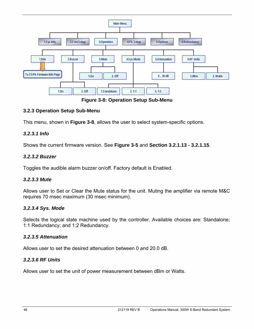
46 212119 REV B Operations Manual, 300W S-Band Redundant System
3.2.3 Operation Setup Sub-Menu This menu, shown in Figure 3-8, allows the user to select system-specific options. 3.2.3.1 Info Shows the current firmware version. See Figure 3-5 and Section 3.2.1.13 - 3.2.1.15. 3.2.3.2 Buzzer Toggles the audible alarm buzzer on/off. Factory default is Enabled. 3.2.3.3 Mute Allows user to Set or Clear the Mute status for the unit. Muting the amplifier via remote M&C requires 70 msec maximum (30 msec minimum). 3.2.3.4 Sys. Mode Selects the logical state machine used by the controller. Available choices are: Standalone; 1:1 Redundancy; and 1:2 Redundancy. 3.2.3.5 Attenuation Allows user to set the desired attenuation between 0 and 20.0 dB. 3.2.3.6 RF Units Allows user to set the unit of power measurement between dBm or Watts.
2.Com Setup1.Sys Info
2.Buzzer
3.Operation 4.Flt. Setup 5.Options
1.Info
Main Menu
6.Redundancy
3.Mute 4.Sys.Mode 5.Attenuation 6.RF Units
1.Standalone
0 .. 20 dB
2. 1:11.On 2. Off
1.On 2. Off
3. 1:2
1.dBm 2. WattsTo SSPA Firmware Info Page
Figure 3-8: Operation Setup Sub-Menu
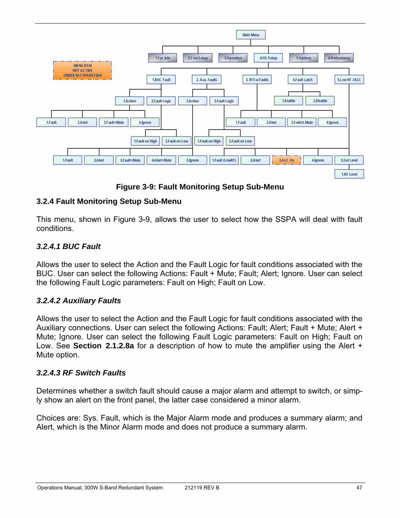
Operations Manual, 300W S-Band Redundant System 212119 REV B 47
3.2.4 Fault Monitoring Setup Sub-Menu This menu, shown in Figure 3-9, allows the user to select how the SSPA will deal with fault conditions. 3.2.4.1 BUC Fault Allows the user to select the Action and the Fault Logic for fault conditions associated with the BUC. User can select the following Actions: Fault + Mute; Fault; Alert; Ignore. User can select the following Fault Logic parameters: Fault on High; Fault on Low. 3.2.4.2 Auxiliary Faults Allows the user to select the Action and the Fault Logic for fault conditions associated with the Auxiliary connections. User can select the following Actions: Fault; Alert; Fault + Mute; Alert + Mute; Ignore. User can select the following Fault Logic parameters: Fault on High; Fault on Low. See Section 2.1.2.8a for a description of how to mute the amplifier using the Alert + Mute option. 3.2.4.3 RF Switch Faults Determines whether a switch fault should cause a major alarm and attempt to switch, or simp-ly show an alert on the front panel, the latter case considered a minor alarm. Choices are: Sys. Fault, which is the Major Alarm mode and produces a summary alarm; and Alert, which is the Minor Alarm mode and does not produce a summary alarm.
Figure 3-9: Fault Monitoring Setup Sub-Menu
2.Com Setup1.Sys Info 3.Operation 4.Flt. Setup 5.Options
1.BUC Fault
Main Menu
6.Redundancy
2. Aux. Faults 3. RFSw Faults 4.Fault Latch
1.Enable 2.Disable
5.Low RF / ALC
1.Fault 4.Ignore3.Switch Mute2.Alert
1.Fault (LowRF) 4.Ignore3.ALC On2.Alert
1.Action 2.Fault Logic
1.Fault 4.Ignore3.Fault+Mute2.Alert
1.Fault on High 2.Fault on Low
1.Action 2.Fault Logic
1.Fault 5.Ignore3.Fault+Mute2.Alert
1.Fault on High 2.Fault on Low
5.Set Level
1.RF Level
MENU ITEMNOT ACTIVE
UNDER N+1 OPERATION
4.Alert+Mute
48 212119 REV B Operations Manual, 300W S-Band Redundant System
3.2.4.4 Fault Latch Determines the alarm reporting condition. A latched alarm will remain indicated on the front panel until the operator clears the alarm by pressing the Enter key. Unlatched alarms will allow the summary alarm indicator to stop displaying the alarm condition if the circumstance creating the alarm has been cleared or corrected. 3.2.4.5 Low RF / Automatic Level Control This function alerts the operator when the output power falls below the threshold value, which is adjustable by the operator. Fault handling is adjustable by the operator, who may choose between Alert Only (Minor Fault), Fault (Major Fault), and Ignore (No Fault tracking). In addition, the user may select Automatic Level Control from this menu.
1. Select 3.ALC On and press the Enter key; 2. Select 5.Set Level and press the Enter key; 3. Use the Arrow keys to set the desired output level (in 0.1 dB steps). 4. Press the Enter key to lock in the selection.
Once activated, the ALC will take control of the amplifier’s attenuation setting to maintain the desired RF output power level and will not allow any attenuation adjustments via the front panel. The ALC circuit will have the greatest ability to adjust for positive and negative RF in-put level changes when the amplifier’s gain level is typically 65 dB. By following the steps below, the optimum ALC RF input level can be set quickly.
1. Using the front panel menu, make sure the amplifier is not in ALC mode; 2. Set the amplifier attenuation level to 10 dB; 3. Apply a CW RF signal to the amplifier; 4. Use a power meter to measure the output power of the amplifier; 5. Adjust the RF input level until the desired output power level is achieved; 6. Follow the steps listed above to activate the ALC control. The ALC will take over
the control of the output level and maintain the RF output level set point. The ALC has the ability to accurately control the RF output power over a 15 dB range from Psat. The ALC will operate over a 20 dB range, but the accuracy of the last 5 dB will suffer. For example, if the saturated power from the amplifier is 59 dBm, the lowest accurate power setting during ALC control is 44 dBm. If the output power set point is set outside the operational range of the ALC circuit, the ALC will adjust the output power to the lowest possible level and set a minor fault on the amplifier’s front panel.
Note: Automatic Level Control is inactive when the system is in N+1 operation.

Operations Manual, 300W S-Band Redundant System 212119 REV B 49
3.2.5 Options Sub-menu This menu makes available functions to backup or restore settings, set a password or the speed of the fans, and test the LED lamps on the front panel. See Figure 3-10. 3.2.5.1 Backup User Settings Allows the user to backup all settings to nonvolatile memory. 3.2.5.2 Restore Restores saved settings, either those from a previous backup (User), or to those as shipped from the factory (Factory). 3.2.5.3 Lamp Test This selection activates all LED indicators on the front panel, including the Fault Indicators, Amplifier Selection, Signal Path Mimic Display, Local/Remote Key and Auto/Manual Key. Press “Enter” to exit the Lamp Test. 3.2.5.4 Password Allows the user to set (Enable), change or clear (Disable) a password that prohibits others from changing controller settings. A number from 1-255 can be selected. Use front panel nav-igation keys to set the number. Up/Down arrows change the number by factors of 10. Right arrows change the number in increments of 1.
2.Com Setup1.Sys Info 3.Operation 4.Flt. Setup 5.Options
1.Backup
Main Menu
6.Redundancy
2.Restore 3.Lamp Test 4.Password 5.Fan Speed 6.Reset
1.User Settings 2.Fctry Settings
1.Set 2.Clear 3.Change
0..255
1.Low 2.High 3.Auto
1.I/O Card Only 2.I/O Card & RF Module
Figure 3-10: Options Sub-Menu
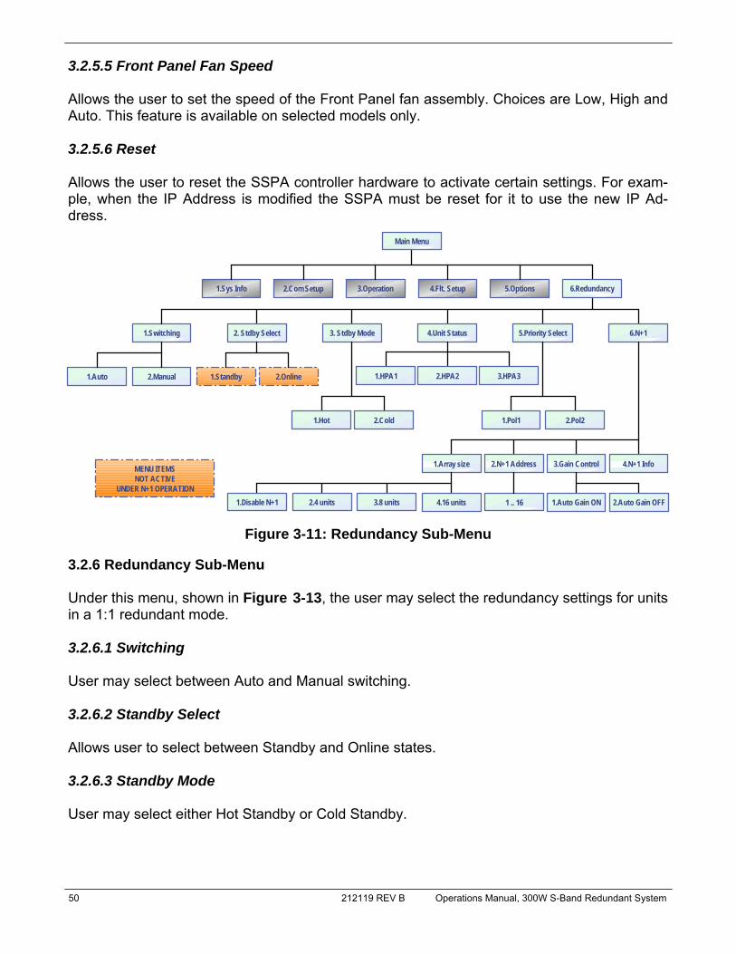
50 212119 REV B Operations Manual, 300W S-Band Redundant System
3.2.5.5 Front Panel Fan Speed Allows the user to set the speed of the Front Panel fan assembly. Choices are Low, High and Auto. This feature is available on selected models only. 3.2.5.6 Reset Allows the user to reset the SSPA controller hardware to activate certain settings. For exam-ple, when the IP Address is modified the SSPA must be reset for it to use the new IP Ad-dress.
3.2.6 Redundancy Sub-Menu Under this menu, shown in Figure 3-13, the user may select the redundancy settings for units in a 1:1 redundant mode. 3.2.6.1 Switching User may select between Auto and Manual switching. 3.2.6.2 Standby Select Allows user to select between Standby and Online states. 3.2.6.3 Standby Mode User may select either Hot Standby or Cold Standby.
2.Com Setup1.Sys Info 3.Operation 4.Flt. Setup 5.Options
1.Switching
Main Menu
6.Redundancy
2. Stdby Select 3. Stdby Mode 4.Unit Status
1.HPA1 2.HPA2
5.Priority Select
1.Hot 2.Cold 1.Pol1 2.Pol2
1.Auto 2.Manual 1.Standby 2.Online
6.N+1
3.HPA3
1.Array size 2.N+1 Address 3.Gain Control
1.Disable N+1 2.4 units 3.8 units 4.16 units 1.Auto Gain ON1 .. 16
MENU ITEMSNOT ACTIVE
UNDER N+1 OPERATION2.Auto Gain OFF
4.N+1 Info
Figure 3-11: Redundancy Sub-Menu
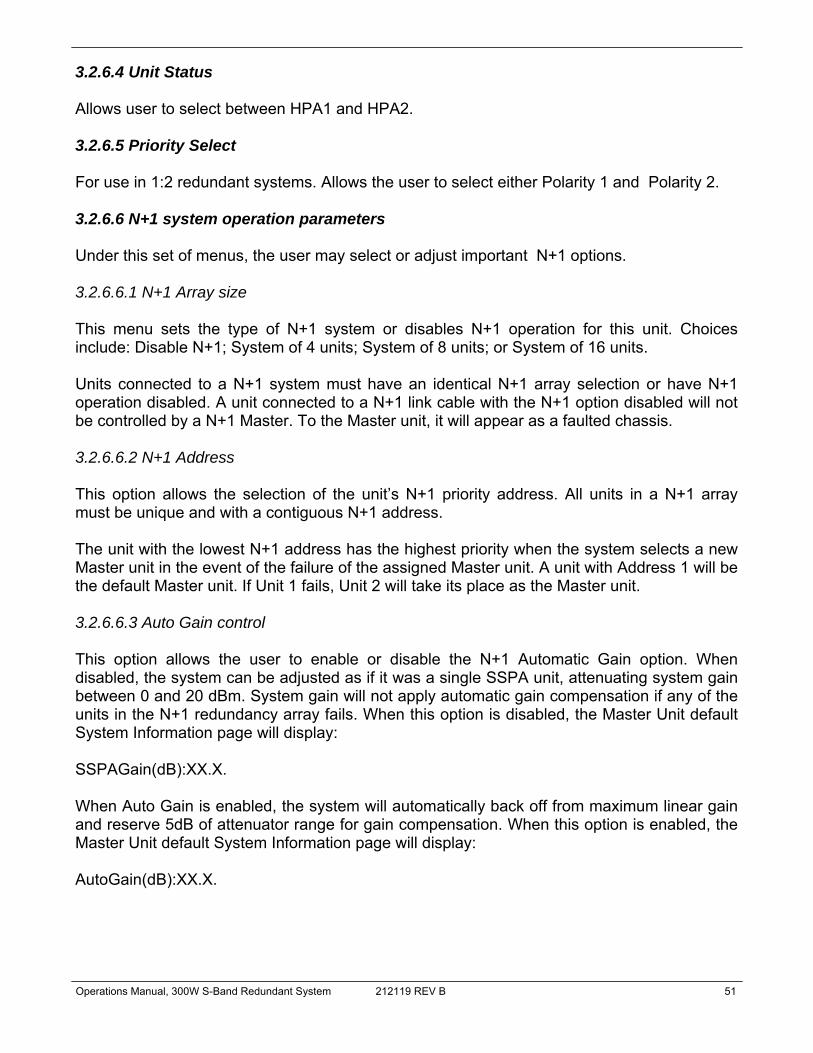
Operations Manual, 300W S-Band Redundant System 212119 REV B 51
3.2.6.4 Unit Status Allows user to select between HPA1 and HPA2. 3.2.6.5 Priority Select For use in 1:2 redundant systems. Allows the user to select either Polarity 1 and Polarity 2. 3.2.6.6 N+1 system operation parameters Under this set of menus, the user may select or adjust important N+1 options. 3.2.6.6.1 N+1 Array size This menu sets the type of N+1 system or disables N+1 operation for this unit. Choices include: Disable N+1; System of 4 units; System of 8 units; or System of 16 units. Units connected to a N+1 system must have an identical N+1 array selection or have N+1 operation disabled. A unit connected to a N+1 link cable with the N+1 option disabled will not be controlled by a N+1 Master. To the Master unit, it will appear as a faulted chassis. 3.2.6.6.2 N+1 Address This option allows the selection of the unit’s N+1 priority address. All units in a N+1 array must be unique and with a contiguous N+1 address. The unit with the lowest N+1 address has the highest priority when the system selects a new Master unit in the event of the failure of the assigned Master unit. A unit with Address 1 will be the default Master unit. If Unit 1 fails, Unit 2 will take its place as the Master unit. 3.2.6.6.3 Auto Gain control This option allows the user to enable or disable the N+1 Automatic Gain option. When disabled, the system can be adjusted as if it was a single SSPA unit, attenuating system gain between 0 and 20 dBm. System gain will not apply automatic gain compensation if any of the units in the N+1 redundancy array fails. When this option is disabled, the Master Unit default System Information page will display: SSPAGain(dB):XX.X. When Auto Gain is enabled, the system will automatically back off from maximum linear gain and reserve 5dB of attenuator range for gain compensation. When this option is enabled, the Master Unit default System Information page will display: AutoGain(dB):XX.X.

52 212119 REV B Operations Manual, 300W S-Band Redundant System
3.2.6.6.4 N+1 Info When selected, the menu shown in Figure 3-12 is displayed. The values shown are used in N+1 system troubleshooting.
Note: The values shown do not indicate the current system state, but instead offer a history of any fault occurrences.
Last Fault/Ticks — shows different information for Master and Slave units. On the Master unit, it displays the unit address of the last detected fault in the N+1 system. If the display shows “000”, that indicates no fault instances since the unit assumed its Master state. On Slave units, the value displays the amount of system clock tick remaining since the last Mas-ter unit call. The Slave unit will assume Master state when the tick count reaches 0. Fault Cause — Master unit only. Displays the cause for the last detected N+1 unit fault. Possible values include “None,” for no faults; “Timeout,” if a Slave unit fails to respond to a Master request for three (3) consecutive queries; or “Summary,” if a unit exhibited a Summary fault.
Figure 3-12: N+1 Info menu
LastFault/Ticks: XX Fault Cause: XXXXXX
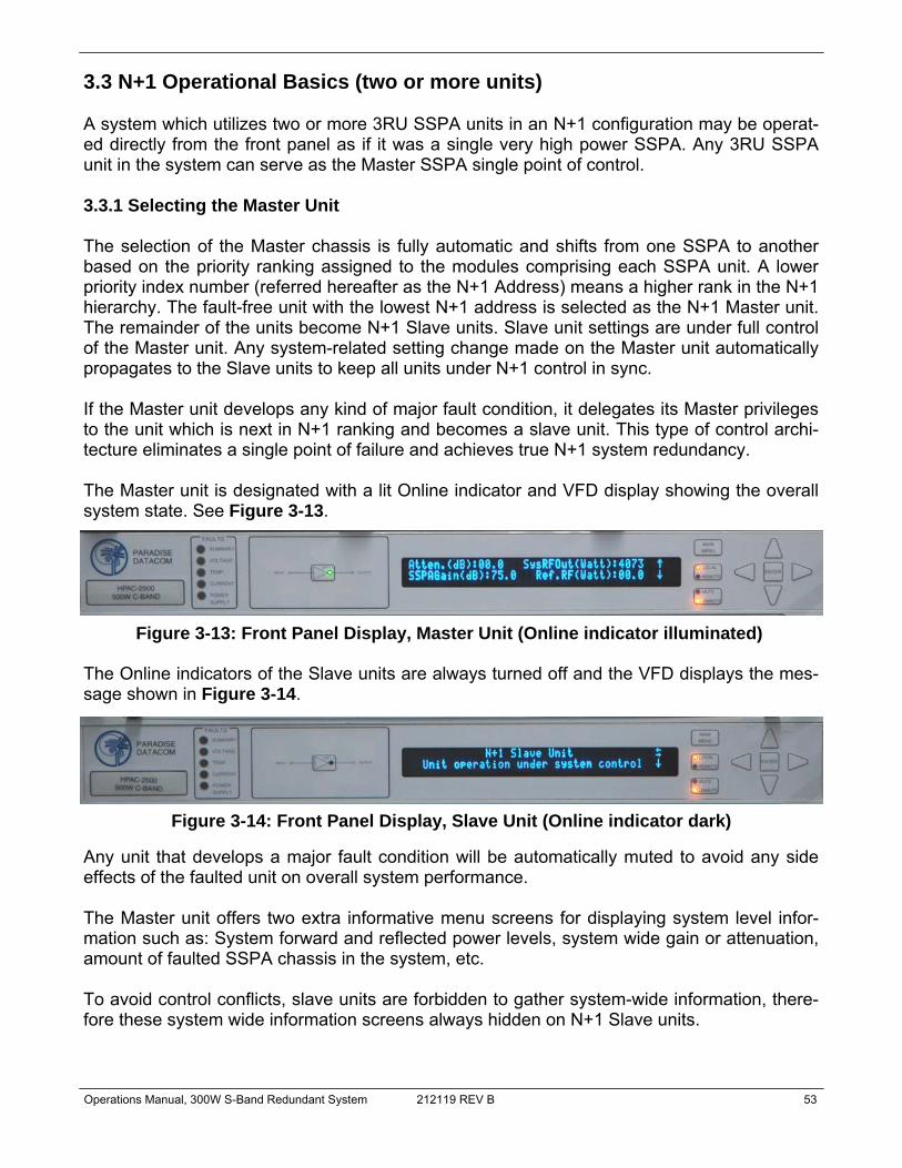
Operations Manual, 300W S-Band Redundant System 212119 REV B 53
3.3 N+1 Operational Basics (two or more units) A system which utilizes two or more 3RU SSPA units in an N+1 configuration may be operat-ed directly from the front panel as if it was a single very high power SSPA. Any 3RU SSPA unit in the system can serve as the Master SSPA single point of control. 3.3.1 Selecting the Master Unit The selection of the Master chassis is fully automatic and shifts from one SSPA to another based on the priority ranking assigned to the modules comprising each SSPA unit. A lower priority index number (referred hereafter as the N+1 Address) means a higher rank in the N+1 hierarchy. The fault-free unit with the lowest N+1 address is selected as the N+1 Master unit. The remainder of the units become N+1 Slave units. Slave unit settings are under full control of the Master unit. Any system-related setting change made on the Master unit automatically propagates to the Slave units to keep all units under N+1 control in sync. If the Master unit develops any kind of major fault condition, it delegates its Master privileges to the unit which is next in N+1 ranking and becomes a slave unit. This type of control archi-tecture eliminates a single point of failure and achieves true N+1 system redundancy. The Master unit is designated with a lit Online indicator and VFD display showing the overall system state. See Figure 3-13.
The Online indicators of the Slave units are always turned off and the VFD displays the mes-sage shown in Figure 3-14.
Any unit that develops a major fault condition will be automatically muted to avoid any side effects of the faulted unit on overall system performance. The Master unit offers two extra informative menu screens for displaying system level infor-mation such as: System forward and reflected power levels, system wide gain or attenuation, amount of faulted SSPA chassis in the system, etc. To avoid control conflicts, slave units are forbidden to gather system-wide information, there-fore these system wide information screens always hidden on N+1 Slave units.
Figure 3-13: Front Panel Display, Master Unit (Online indicator illuminated)
Figure 3-14: Front Panel Display, Slave Unit (Online indicator dark)
54 212119 REV B Operations Manual, 300W S-Band Redundant System
3.3.2 Controlling system operation The N+1 system is under the control of the Master SSPA unit at all times. Any system-wide settings changes (local or remote) need to be performed on the Master unit. If a setting is ad-justed on a Slave unit, the Master unit will erase and override it with the current system set-ting. Some settings are not controlled by the Master unit because they are used for unit identifica-tion or required for local adjustment during maintenance. Settings such as the SSPA Network Address, N+1 Address, and IP Address are not enforced by the Master unit and need to be set individually at every SSPA chassis. The setting for enabling/disabling/sizing the N+1 system is also not controlled by the Master unit. This setting allows the user to virtually remove individual SSPA units from the N+1 con-trol array for maintenance and troubleshooting. 3.3.3 N+1 Addressing During initial system installation, an appropriate N+1 address has to be selected for each unit in the system. Each unit should be assigned a unique N+1 address. The valid addressing range is 1 to 16 for any type of system configuration. Address 0 is reserved for factory debug-ging and should not be used. Assigning an address higher than the total number of SSPA chassis in the system (i.e., address 10 for a system comprising four 3RU SSPA units) makes the unit thus assigned invisible to the Master unit. The unit will continue to receive commands from the Master unit. To set the N+1 address of a particular SSPA unit, press the Main Menu key; select 6.Redundancy and press the Enter key; select 6.N+1 and press the Enter key; select 2.N+1 Addressing and press the Enter key. Enter the desired address by using the Left Arrow [◄] and Right Arrow [►] keys to increment the ones place and the Up Arrow [▲] and Down Arrow [▼] keys to increment the tens place. The order of the N+1 addressing is not important for system operation. The lowest address should be assigned to the unit located most conveniently for the operator. All subsequent ad-dresses should be assigned while keeping in mind the accessibility of the front panel controls. 3.3.4 Adjust system gain Nominal system gain with Auto Gain enabled is 65 dB; nominal system gain with Auto Gain disabled is 70 dB. To adjust the gain of the system, press the Main Menu key; select 3.Operation and press the Enter key; select 5.Attenuation and press the Enter key; select the desired attenuation value by using the Left Arrow [◄] and Right Arrow [►] keys to increment the ones place and the Up Arrow [▲] and Down Arrow [▼] keys to increment the tens place. Alternately, from any of the System Information menus described in Section 3.2.1, press the Left Arrow [◄] or Right Arrow [►] key.
Operations Manual, 300W S-Band Redundant System 212119 REV B 55
3.3.5 N+1 Automatic gain control option Any modular hitless SSPA system may exhibit natural gain drift when one or more individual SSPA chassis is removed from the system or malfunctions. The automatic gain control option allows the system to maintain a constant gain level during such events. This feature is user selectable and can be activated from the SSPA front panel or a remote interface. To toggle the Automatic Gain Control option, press the Main Menu key; select 6.Redundancy and press the Enter key; select 6.N+1 and press the Enter key; select 3.Gain Control and press the Enter key. Select either Auto Gain On or Auto Gain Off. When this option is activated [Auto Gain On], the SSPA will automatically reserve 5 dB of attenuator range for future gain compensation. This will reduce the maximum SSPA gain by 5 dB. The attenuator range will also be reduced to 15 dB. Five dB of reserved attenuator range allows the system to fully auto compensate gain when one SSPA module in a single 3RU SSPA unit enters a fault condition. 3.3.6 N+1 RF power measurements The N+1 system may be equipped with a dedicated RF power measurement unit. The RF Power Detector provides RMS measurement of Forward and Reflected RF power directly at the output waveguide and this reading is acquired by the N+1 Master unit. Besides N+1 system level power detection, each individual SSPA unit may be equipped with its own RF power detector. This reading can be viewed at each SSPA unit and may be used for troubleshooting individual SSPA units. To view the RF power detector reading on the front panel, select the [MAIN MENU] key → 1.SysInfo → down [▼] arrow to get to Sys Info Page 1. 3.3.7 N+1 Fault Detection The N+1 system carries comprehensive fault detection logic. Each SSPA chassis processes its internal fault conditions as if it was a standalone unit. All N+1 Slave units report any fault state to the Master unit, which is responsible for system wide fault state handling. Failure of any single SSPA unit leads to a minor N+1 alarm on the Master unit. This type of fault condi-tion will not produce a summary system alarm. The user may view the number of faults in a system from the front panel by pressing the Main Menu key of the Master unit, then pressing the Up Arrow [▲] key to get to N+1 Master Info Page 2. Any detected SSPA unit alarms present in the system will be displayed at the “N+1 Alarms” screen. If the Master unit detects two or more failed units, it will report a system-wide Summary alarm (Summary alarm LED on the Master unit will illuminate). The cause of the alarm will not be evaluated by the Master unit. To find cause of the failure, the operator will need to evaluate the local fault conditions of the failed SSPA unit.

56 212119 REV B Operations Manual, 300W S-Band Redundant System
3.4 Reflected Power Option When this option is installed, the user may measure the amount of reflected RF power pre-sent at the amplifier’s output flange, with a dynamic range of 12 dB starting at the maximum RF output. For example, an amplifier with 50 dBm (100W) of maximum forward RF would be capable of reading reflected power levels from 38 dBm (6W) to 50 dBm (100W). The amount of reflected power can be viewed on the front panel display screen; select Main Menu → 1.Sys Info. 3.4.1 Reflected Power Alarm Because the reflected power circuitry is not a true VSWR measurement, but simply a meas-ure of absolute reflected power, it is possible to set an alarm level. The alarm level is factory pre-set at 80% of the HPA’s rated power. For example, an amplifier with 50 dBm (100W) of output power would have an alarm level set to 49 dBm (80W). The alarm level is not user se-lectable due to possible frequent false alarms that may be generated if set at a much lower level. The reflected power is reported to the M&C and the user can set adjustable alarms us-ing their M&C application.
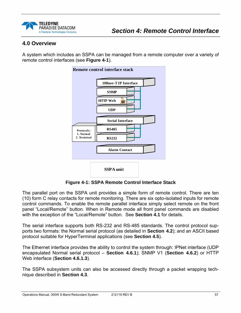
Operations Manual, 300W S-Band Redundant System 212119 REV B 57
4.0 Overview A system which includes an SSPA can be managed from a remote computer over a variety of remote control interfaces (see Figure 4-1).
The parallel port on the SSPA unit provides a simple form of remote control. There are ten (10) form C relay contacts for remote monitoring. There are six opto-isolated inputs for remote control commands. To enable the remote parallel interface simply select remote on the front panel “Local/Remote” button. When in Remote mode all front panel commands are disabled with the exception of the “Local/Remote” button. See Section 4.1 for details. The serial interface supports both RS-232 and RS-485 standards. The control protocol sup-ports two formats: the Normal serial protocol (as detailed in Section 4.2); and an ASCII based protocol suitable for HyperTerminal applications (see Section 4.5). The Ethernet interface provides the ability to control the system through: IPNet interface (UDP encapsulated Normal serial protocol – Section 4.6.1); SNMP V1 (Section 4.6.2) or HTTP Web interface (Section 4.6.1.3). The SSPA subsystem units can also be accessed directly through a packet wrapping tech-nique described in Section 4.3.
Section 4: Remote Control Interface
Remote control interface stack
SNMP
HTTP Web
10Base-T IP Interface
UDP
Alarm Contact
Protocols:1. Normal
2. Terminal
RS485
RS232
Serial Interface
SSPA unit
Figure 4-1: SSPA Remote Control Interface Stack

58 212119 REV B Operations Manual, 300W S-Band Redundant System
Serial protocol format is set at no parity, 8 bit with 1 stop bit. Baud rate is selectable through the front panel. If using a Terminal mode protocol, the SSPA provides remote menu access through a Hyper-Terminal program or through an actual hardware terminal. The Ethernet interface is fixed to the 10Base-T standard. Normally, straight-through Cat5 ca-ble is used to connect the SSPA to a network hub, and crossover Cat5 is used to connect di-rectly to a computer’s Ethernet port. 4.1 Remote Control - Parallel 4.1.1 Control Outputs The hardware behind the form C relay is a single pole, double throw relay. Under normal operation (no alarms) the relays are in an energized state. When a fault occurs or the control-ler is powered off, the relays are in a de-energized state. The relay contacts are capable of handling a maximum of 30 VDC @ 1A . The form C relay is shown schematically in Figure 4-2. The form C relay contact outputs are listed in Table 2-2.
Common
Relay Energized
Closed on Fault
Open on Fault
Common
Relay de-Energized
Closed on Fault
Open on Fault
Figure 4-2: Parallel I/O Form C Relay

Operations Manual, 300W S-Band Redundant System 212119 REV B 59
4.1.2 Control Inputs The parallel control inputs are opto-isolated inputs with pull up resistors. To trigger a remote input command, the input should be pulled to ground. The input does not need to be held to ground continuously but it is acceptable to do so. The input only need be pulled low for a min-imum of 50 msec. For example, to make amplifier #2 the standby amplifier, pulse pin 36 to ground for 50 msec. If the operator then chooses to make amplifier #1 the standby amplifier, simply pulse pin 37 to ground for 50 msec. The schematic representation of the control input is shown in Figure 4-3. The external alarm and auxiliary alarm inputs use the same opto-isolated input circuitry shown in Figure 4-3.
3.3K
560
+5 VDC
Control Input
Opto-Isolator
Transorb
Figure 4-3: Opto-Isolated Parallel I/O Input

60 212119 REV B Operations Manual, 300W S-Band Redundant System
4.2 Serial Communication Protocol This section describes the basic serial communication protocol between the SSPA and host computer. The amplifier will only respond to properly formatted protocol packets. The basic communication packet is shown in Figure 4-4. It consists of a Header, Data and Trailer sub-packet.
4.2.1 Header Sub-Packet The Header packet is divided into 3 sub-packets which are the Frame Sync, Destination Ad-dress and Source Address packets (See Figure 4-5).
4.2.1.1 Frame Sync Word The Frame Sync word is a two byte field that marks the beginning of a packet. This value is always 0xAA55. This field provides a means of designating a specific amplifier packet from others that may exist on the same network. It also provides a mechanism for a node to syn-chronize to a known point of transmission. 4.2.1.2 Destination Address The destination address field specifies the node for which the packet is intended. It may be an individual or broadcast address. The broadcast address is 0xFF. This is used when a packet of information is intended for several nodes on the network. The broadcast address can be used in a single device connection when the host needs to determine the address of the am-plifier. The amplifier will reply with its unique address. 4.2.1.3 Source Address The source address specifies the address of the node that is sending the packet. All unique addresses, except the broadcast address, are equal and can be assigned to individual units. The host computer must also have a unique network address.
HEADER (4 bytes)
DATA (6-32 bytes)
Figure 4-4: Basic Communication Packet
TRAILER (1 byte)
HEADER (4 bytes)
DATA (6-32 bytes)
TRAILER (1 byte)
Frame Sync (2 bytes) 0xAA5
Destination Address (1 byte)
Source Address (1 byte)
Figure 4-5: Header Sub-Packet

Operations Manual, 300W S-Band Redundant System 212119 REV B 61
4.2.2 Data Packet The data sub-packet is comprised of 6 to 32 bytes of information. It is further divided into sev-en (7) fields as shown in Figure 4-6. The first six (6) fields comprise the command preamble while the last field is the actual data.
4.2.2.1 Protocol ID This field provides backward compatibility with older generation equipment protocol. It should normally be set to zero (0). This field allows the amplifier to auto-detect other firmware ver-sions. 4.2.2.2 Request ID This is an application specific field. The amplifier will echo this byte back in the response frame without change. This byte serves as a request tracking feature. 4.2.2.3 Command This one byte field tells the receiver how to use the attached data. There are only four (4) possible values for this field. The sender and receiver are limited to two commands. For ex-ample: if the sender issued “Set Request” command, receiver must answer with “Get Re-quest” and “Get Response” form of the command. The byte value for each command is given in Table 4-1.
HEADER (4 bytes)
DATA (6-32 bytes)
TRAILER (1 byte)
DATA FIELD
Protocol ID 1 Byte
Request ID 1 Byte
Command 1 Byte
Data Tag 1 Byte
Error Status / Data Address
1 Byte
Data Length 1 Byte
Command Data Sub Structure 0 - 26 Bytes
COMMAND PREAMBLE
Figure 4-6: Data Sub-Packet
Command Name Command Byte Value Set Request 0
Get Request 1
Set Response 2
Get Response 3
Table 4-1: Command Byte Values
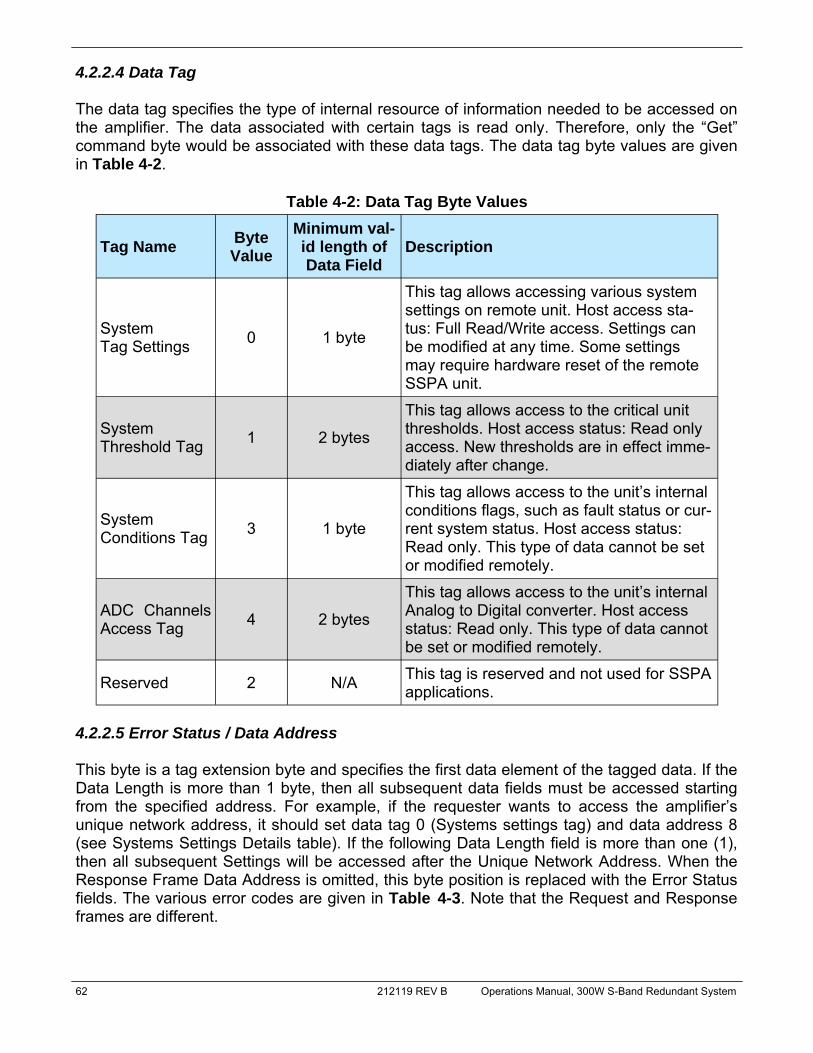
62 212119 REV B Operations Manual, 300W S-Band Redundant System
4.2.2.4 Data Tag The data tag specifies the type of internal resource of information needed to be accessed on the amplifier. The data associated with certain tags is read only. Therefore, only the “Get” command byte would be associated with these data tags. The data tag byte values are given in Table 4-2.
4.2.2.5 Error Status / Data Address This byte is a tag extension byte and specifies the first data element of the tagged data. If the Data Length is more than 1 byte, then all subsequent data fields must be accessed starting from the specified address. For example, if the requester wants to access the amplifier’s unique network address, it should set data tag 0 (Systems settings tag) and data address 8 (see Systems Settings Details table). If the following Data Length field is more than one (1), then all subsequent Settings will be accessed after the Unique Network Address. When the Response Frame Data Address is omitted, this byte position is replaced with the Error Status fields. The various error codes are given in Table 4-3. Note that the Request and Response frames are different.
Tag Name Byte Value
Minimum val-id length of Data Field
Description
System Tag Settings 0 1 byte
This tag allows accessing various system settings on remote unit. Host access sta-tus: Full Read/Write access. Settings can be modified at any time. Some settings may require hardware reset of the remote SSPA unit.
System Threshold Tag 1 2 bytes
This tag allows access to the critical unit thresholds. Host access status: Read only access. New thresholds are in effect imme-diately after change.
System Conditions Tag 3 1 byte
This tag allows access to the unit’s internal conditions flags, such as fault status or cur-rent system status. Host access status: Read only. This type of data cannot be set or modified remotely.
ADC Channels Access Tag 4 2 bytes
This tag allows access to the unit’s internal Analog to Digital converter. Host access status: Read only. This type of data cannot be set or modified remotely.
Reserved 2 N/A This tag is reserved and not used for SSPA applications.
Table 4-2: Data Tag Byte Values

Operations Manual, 300W S-Band Redundant System 212119 REV B 63
4.2.2.6 Data Length This byte contains different information for Request and Response frames. In a Request frame, it specifies the number of data bytes that are to be accessed starting from the first byte of the value specified in the Data Address byte. That byte must not exceed the maxi-mum data bytes from a particular tag. The maximum data length for the Settings tag is 26 bytes. The maximum data length for the System Threshold tag is six (6) bytes. 4.2.2.7 Data Field The actual data contained in the packet must be placed in this field. The “Get Request” type of command must not contain any Data Field. Any “Get Request” will be rejected if any data is present in the Data Field. Generally, the Bad Checksum error code will be added to the re-sponse from the amplifier if the word size of the information is 16-bits or 2-bytes. Each data word is placed in the frame with its least significant byte first. All data with length of 2 bytes must be represented as integer type with maximum value range from 32767 to (-32767).
Error Code Name Byte Value Possible Cause No Errors 0 Normal Condition, no errors detected
Data Frame Too Big 1 Specified Data length is too big for amplifier buffer to accept
No Such Data 2 Specified Data Address is out of bounds for this tag data
Bad Value 3 Specified value not suitable for this particu-lar data type
Read Only 4 Originator tried to set a value which has read only status
Bad Checksum 5 Trailer checksum not matched to calculated checksum
Unrecognizable Error 6 Error presented in incoming framed, but SSPA failed to recognize it. All data aborted
Table 4-3: Error Status Byte Values

64 212119 REV B Operations Manual, 300W S-Band Redundant System
4.2.3 Trailer Packet 4.2.3.1 Frame Check The trailer component contains only one (1) byte called the Frame Check Sequence, shown in Figure 4-7.
This field provides a checksum during packet transmission. This value is computed as a func-tion of the content of the destination address, source address and all Command Data Sub-structure bytes. In general, the sender formats a message frame, calculates the check se-quence, appends it to the frame, then transmits the packet. Upon receipt, the destination node recalculates the check sequence and compares it to the check sequence embedded in the frame. If the check sequences are the same, the data was transmitted without error. Oth-erwise an error has occurred and some form of recovery should take place. In this case, the amplifier will return a packet with the “Bad Checksum” error code set. Checksums are gener-ated by summing the value of each byte in the packet while ignoring any carry bits. A simple algorithm is given as: Chksum=0 FOR byte_index=0 TO byte_index=packet_len-1 Chksum=(chksum+BYTE[byte_index]) MOD 256 NEXT byte_index 4.2.4 Timing issues There is no maximum specification on the inter-character spacing in messages. Bytes in mes-sages to amplifier units may be spaced as far apart as you wish. The amplifier will respond as soon as it has collected enough bytes to determine the message. Generally, there will be no spacing between characters in replies generated by unites. The maximum length of the pack-et sent to the amplifier node should not exceed 64 bytes, including checksum and frame sync bytes. Inter-message spacing must be provided for good data transmission. The minimum spacing should be 100 ms. This time is required for the controller to detect a “Line Cleared” condition with half duplex communications. Maximum controller respond time is 200 ms.
HEADER (4 bytes)
DATA (6-32 bytes)
TRAILER (1 byte)
Frame Check Checksum (1 byte)
Figure 4-7: Trailer Sub-Packet

Operations Manual, 300W S-Band Redundant System 212119 REV B 65
4.3 Access SSPA subsystem through Packet Wrapper technique Features introduced in firmware version 4.03 allow send requests directly to a remote SSPA subsystem. In this mode, the RCP redirects requests from its Serial Main or Ethernet port to its Local serial port, connected to the SSPA (see Figure 4-8). Packet wrapper requests are associated with longer response times, which have to be accounted in the host M&C soft-ware. This mode can be useful for advanced remote diagnostic of the attached SSPA subsys-tem. All Packet Wrapper request frames must be “Data Set” command requests. Each frame in-tended for redirection must be included in request packet Data Fields. Packet Wrapping frame M&C should follow the same rules as for any other request frames with one exclusion — the Data Address field will represent the number of bytes expected back from the remote SSPA. These bytes will be redirected back to the Host M&C in the Data Field response pack-et. The response packet will not be sent until the specified number of bytes is collected in the RCP2 buffer. Maximum length of the data fields in both directions should not exceed 32 bytes. In the dia-gram represented in Figure 4-8, Request frame A is the Packet Wrapper frame. It contains Request frame B, intended to be redirected to the remote SSPA.
Note: In general, data length must be at least two (2) bytes to form an integer; the lower byte must come first. If an odd number of bytes arrived, the last data byte in the packet will be saved as the lower part of the integer; the upper part will be 0 by default.
Protocol ID0
Request ID0 to 255
Command0 - 1
Data Tag6
Response Lengthn = 11 + m
Data Length11 to 11 + m
Header4 Bytes
Command Preamble6 Bytes
Request Frame B11 to 11 + n Bytes
Trailer Checksum1 Byte
Request Frame A
Protocol ID0
Request ID0 to 255
Command0 - 1
Data Tag0 - 4
Data Address0 to 255
Data Lengthm = 1 to 128
Header4 Bytes
Command Preamble6 Bytes
Data Field0 to m Bytes
Trailer Checksum1 Byte
Request Frame B
Protocol ID0
Request ID0 to 255
Command2 - 3
Data Tag6
Error Status0 to 5
Data Length11 + m
Protocol ID0
Request ID0 to 255
Command2 -3
Data Tag0 - 4
Error Status0 to 5
Data Lengthm = 1 to 128
Header4 Bytes
Command Preamble6 Bytes
ResponseFrame B11 + n Bytes
Trailer Checksum1 Byte
Response Frame A
Header4 Bytes
Command Preamble6 Bytes
Data Fieldm Bytes
Trailer Checksum1 Byte
Response Frame B
Figure 4-8: Packet Wrapper technique
SSPA Chassis
RCP
Propogation Delay 1-10 mS
Propogation Delay 1-50 mSPropogation Delay 1-50 mS
Host PC
Request Frame A
Response Frame A
Response Frame B
Request Frame B
J5 Local
J4 Main orJ9 Ethernet

66 212119 REV B Operations Manual, 300W S-Band Redundant System
Byte position Byte Value (Hex) Description 1 0xAA Frame Sync 1
2 0x55 Frame Sync 2
3 Destination Address -//-
4 Source Address -//-
5 Protocol Version Protocol compatibility hole, must be set to 0
6 Request ID Service Byte
7 Command 0, Set Request; 1, Get Request
8 Data Tag 0, System Settings; 1, System Thresholds; 2, Temp. Sensor Settings; 3, Conditions; 4, ADC Data; 5, Raw NVRAM/RAM Data
9 Data Address Setting number, Sensor command, EEPROM address
10 Data Length Total length of the data, valid values 1-30
11+N Data Actual Data
11+N+1 Checksum Dest. Address + Source Address + Protocol Version + Request ID + Command + Data Tag + Data Address + Data Length + Data
Table 4-4: Request Frame Structure
Byte position Byte Value (Hex) Description 1 0xAA Frame Sync 1
2 0x55 Frame Sync 2
3 Destination Address -//-
4 Source Address -//-
5 Protocol Version Protocol compatibility hole, must be set to 0
6 Request ID Service Byte
7 Command 2, Set Response; 3, Get Response
8 Data Tag 0, System Settings; 1, System Thresholds; 2, Temp. Sensor Settings; 3, Conditions; 4, ADC Data; 5, Raw NVRAM/RAM Data
9 Error Status 0, No Errors; 1, Too Big; 2, No Such Data; 3, Bad Value; 4, Read Only; 5, Bad Checksum; 6, Unrecognized Error
10 Data Length Total length of the data, valid values 1-30
11+N Data Actual Data
11+N+1 Checksum Dest. Address + Source Address + Protocol Version + Request ID + Command + Data Tag + Data Address + Data Length + Data
Table 4-5: Response Frame Structure

Operations Manual, 300W S-Band Redundant System 212119 REV B 67
Table 4-6: System Setting Details
Data Address
Min. Data Length (bytes)
Description Limits and valid values
0 1 Device Type (read only)
Reserved=0; RM SSPA=1; CO SSPA=2; RCP2/FPRC=3; RCP2-1000-CO=4; RCP2-1000-RM=5; RCP2-1000-RCP=6; VSAT BUC=7 (Version 4.00*)
1 1 System Operational Mode Designator
Standalone Mode = 0; 1:1 Mode = 1; 1:2 Mode = 2 (Version 3.10*); Phase Combined = 3 (Version 4.70*)
2 1 System Switch Mode Manual = 1; Auto = 0
3 1 Control Mode Local = 0; Remote = 1 4 1 Fan Speed Low = 0; High = 1; Auto = 2 5 1 Mute Mute off = 0; Mute on = 1
6 1 Serial Protocol Select Normal = 0; Terminal Mode = 1
7 1 Baud Rate 9600 = 0; 2400 = 1; 4800 = 2; 19200 = 3; 38400 = 4 8 1 Network Address Valid Values: 0 - 255
9 1 Serial Interface RS232 = 0; RS485 = 1; IPNet = 2 (Version 2.50*); SNMP=3 (Version 4.00*)
10 1 Auxiliary Fault Handling
Disable Fault Checking = 0; Major Fault = 1; Minor Fault = 2; Major Fault + Mute = 3; Alert + Mute = 4.
11 1 Auxiliary Fault Log-ic Fault on Logic High = 0; Fault on Logic Low = 1
12 1 RF Switch Fault Handling
Disable Fault Checking = 0; Major Fault = 1; Minor Fault = 2; Switchover Mute = 3
13 1 Fault Latch Enable = 1; Disable = 0
14 1 BUC Fault Handling
Disable Fault Checking = 0; Major Fault = 1; Minor Fault = 2; Major Fault + SSPA Mute = 3
15 1 BUC Fault Logic Fault on Logic High = 0; Fault on Logic Low = 1 16 1 User Password Valid Values = 0 - 255 17 1 Unit Startup State Standby = 0; Online = 1 18 1 Buzzer Disable = 0; Enable = 1
19 1 Menu Password Protection Disable = 0; Enable = 1
20 1 RF Units dBm = 0; Watts = 1 (Version 3.40*)
* Version numbers listed indicate the version in which the listed feature was introduced. (Continued)
21 1 Standby Mode Hot Standby = 0; Cold Standby = 1
22 1 HPA Status HPA1 = 0; HPA2 = 1; HPA3 = 2 (Version 3.10*; 1:2 mode only)

68 212119 REV B Operations Manual, 300W S-Band Redundant System
Table 4-6: System Setting Details (continued from previous page)
Data Address
Min. Data Length (bytes)
Description Limits and valid values
23 1 Priority Select 1:2 mode only Pol1 = 0; Pol2 = 1 (Version 3.10*)
24 1 Low Forward RF Fault Handling
Disable fault checking = 0; Major Fault = 1; Minor Fault = 2
25 1 High Reflected RF Fault Handling
Disable fault checking = 0; Major Fault = 1; Minor Fault = 2
26 1 SSPA Attenuation Valid values = 0 - 200; 0.1 dBm per 1 value 27 1 Low Forward RF Threshold Valid values = 0 - 80; 1 dBm per 1 value
28 1 High Reflected RF Thresh-old Valid values = 0 - 80; 1 dBm per 1 value
29 1 IP Address Byte 1 (MSB)
Field available only for RM SSPA with Ethernet IP Option (See Table 4-8, Field 20
Digital Core Board ID Byte for details) (Version 2.50*)
30 1 IP Address Byte 2 31 1 IP Address Byte 3 32 1 IP Address Byte 4 33 1 IP Gateway Byte 1 34 1 IP Gateway Byte 2 35 1 IP Gateway Byte 3 36 1 IP Gateway Byte 4 (LSB) 37 1 Subnet Mask Byte 1 (MSB) 38 1 Subnet Mask Byte 2 39 1 Subnet Mask Byte 3 40 1 Subnet Mask Byte 4 (LSB)
41 1 Receive IP Port Byte 1 (MSB)
42 1 Receive IP Port Byte 2 (LSB)
43 1 IP Lock Address Byte 1 (MSB)
44 1 IP Lock Address Byte 2 45 1 IP Lock Address Byte 3
46 1 IP Lock Address Byte 4 (LSB)
47 1 N+1 Array size N+1 disabled = 0; Size 2 = 2; Size 4 = 4; Size 8 = 8; Size 16 = 16; Any other numeric value is invalid. (Version 4.20*)
48 1 N+1 Priority Address Valid addresses for array size 4: 1 - 4; Valid ad-dresses for array size 8: 1 - 8; Valid addresses for array size 16: 1 - 16; (Version 4.20*)
49 1 N+1 Auto gain option Auto Gain Off = 0; Auto Gain On = 1; (Version 4.20*)
* Version numbers listed indicate the version in which the listed feature was introduced.

Operations Manual, 300W S-Band Redundant System 212119 REV B 69
Table 4-7: System Threshold Addressing Details (Read Only)
Data Address
Min. Data Length (bytes)
Description Limits and valid values
1 2 Forward RF power If RF Units (Table 3.6, Data Address 20) = 0, then 0.1 dBm per 1 value; If RF Units = 1, then 0.1 Watt per 1 value (Version 3.40*)
2 2 Reflected RF power If RF Units (Table 3.6, Data Address 20) = 0, then 0.1 dBm per 1 value; If RF Units = 1, then 0.1 Watt per 1 value (Version 3.40*)
3 2 SSPA DC Current 0.2A per 1 value; Value will return (-100) if reading is not available at this time.
4 2 Main Power Supply 1 Output Voltage
0.1V per 1 value; Value will return (-100) if reading is not available at this time.
5 2 Main Power Supply 2 Output Voltage
0.1V per 1 value; Value will return (-100) if reading is not available at this time.
6 2 Booster Power Supply 1 Output Voltage
0.1V per 1 value; Value will return (-100) if reading is not available at this time.
7 2 Booster Power Supply 2 Output Voltage
0.1V per 1 value; Value will return (-100) if reading is not available at this time.
8 2 SSPA Core Temperature 1oC per 1 value; Value will return (-100) if reading is not available at this time.
* Version numbers listed indicate the version in which the listed feature was introduced.
9 2 N+1 System Forward Power (available from Master unit
only!)
If RF Units (Table 4-6, Data Address 20) = 0, then 0.1 dBm per 1 value; If RF Units = 1, then 1 Watt per 1 Value. Value will return (-100) if reading is not available at this time. Version 4.20*.
10 2 N+1 Estimated System Gain
(available from Master unit on-ly!)
0.1dB per Value. Estimated N+1 system linear gain. Version 4.20*.
11 2 N+1 System Reflected Power (available from Master unit on-
ly!)
If RF Units (Table 4-6, Data Address 20) = 0, then 0.1 dBm per 1 value; If RF Units = 1, then 1 Watt per 1 Value. Value will return (-100) if reading is not available at this time. Version 4.20*.
12 2 Cabinet Temperature 1°C per 1 value; Value will return (-100) if reading is not available at this time. Version 4.40*.
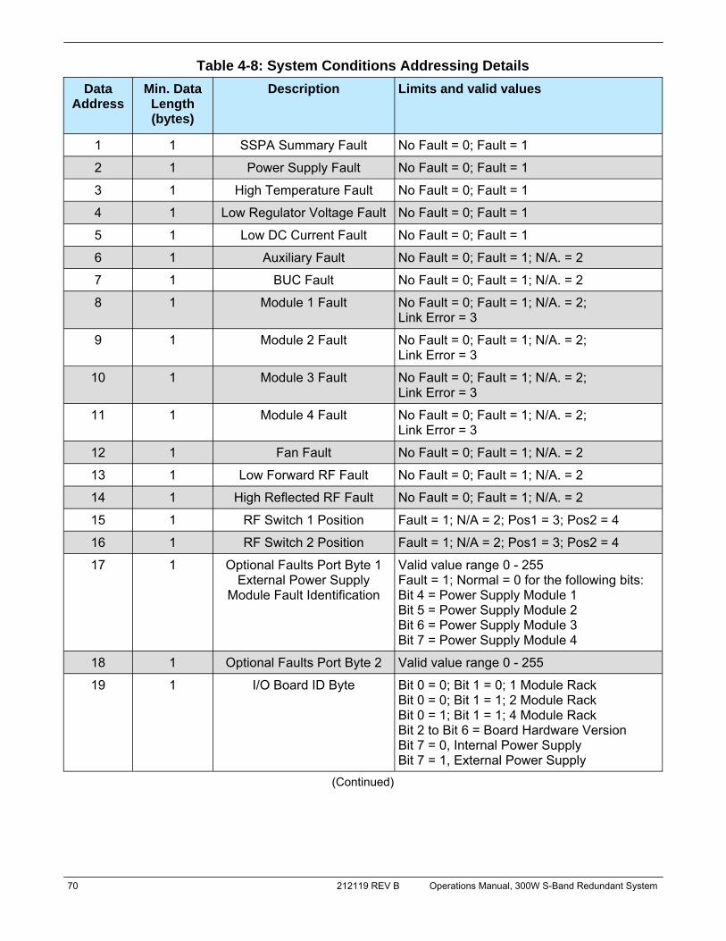
70 212119 REV B Operations Manual, 300W S-Band Redundant System
Table 4-8: System Conditions Addressing Details Data
Address Min. Data
Length (bytes)
Description Limits and valid values
1 1 SSPA Summary Fault No Fault = 0; Fault = 1
2 1 Power Supply Fault No Fault = 0; Fault = 1
3 1 High Temperature Fault No Fault = 0; Fault = 1
4 1 Low Regulator Voltage Fault No Fault = 0; Fault = 1
5 1 Low DC Current Fault No Fault = 0; Fault = 1
6 1 Auxiliary Fault No Fault = 0; Fault = 1; N/A. = 2
7 1 BUC Fault No Fault = 0; Fault = 1; N/A. = 2
8 1 Module 1 Fault No Fault = 0; Fault = 1; N/A. = 2; Link Error = 3
9 1 Module 2 Fault No Fault = 0; Fault = 1; N/A. = 2; Link Error = 3
10 1 Module 3 Fault No Fault = 0; Fault = 1; N/A. = 2; Link Error = 3
11 1 Module 4 Fault No Fault = 0; Fault = 1; N/A. = 2; Link Error = 3
12 1 Fan Fault No Fault = 0; Fault = 1; N/A. = 2
13 1 Low Forward RF Fault No Fault = 0; Fault = 1; N/A. = 2
14 1 High Reflected RF Fault No Fault = 0; Fault = 1; N/A. = 2
15 1 RF Switch 1 Position Fault = 1; N/A = 2; Pos1 = 3; Pos2 = 4
16 1 RF Switch 2 Position Fault = 1; N/A = 2; Pos1 = 3; Pos2 = 4
17 1 Optional Faults Port Byte 1 External Power Supply
Module Fault Identification
Valid value range 0 - 255 Fault = 1; Normal = 0 for the following bits: Bit 4 = Power Supply Module 1 Bit 5 = Power Supply Module 2 Bit 6 = Power Supply Module 3 Bit 7 = Power Supply Module 4
18 1 Optional Faults Port Byte 2 Valid value range 0 - 255
19 1 I/O Board ID Byte Bit 0 = 0; Bit 1 = 0; 1 Module Rack Bit 0 = 0; Bit 1 = 1; 2 Module Rack Bit 0 = 1; Bit 1 = 1; 4 Module Rack Bit 2 to Bit 6 = Board Hardware Version Bit 7 = 0, Internal Power Supply Bit 7 = 1, External Power Supply
(Continued)

Operations Manual, 300W S-Band Redundant System 212119 REV B 71
Table 4-9: ADC Data Addressing Details Data
Address Min. Data
Length (bytes)
Description Limits and valid values
0 2 Current Value of ADC Channel 0
Reserved for future expansion
1 2 Current Value of ADC Channel 1
Reserved for future expansion
2 2 Current Value of ADC Channel 2
Reserved for future expansion
3 2 Current Value of ADC Channel 3
Reserved for Factory use.
4 2 Current Value of ADC Channel 4
Reserved for Factory use.
5 2 Current Value of ADC Channel 5
Reserved for Factory use.
6 2 Current Value of ADC Channel 6
Reserved for Factory use.
7 2 Current Value of ADC Channel 7
Reserved for Factory use.
Table 4-8: System Conditions Addressing Details (continued) Data
Address Min. Data
Length (bytes)
Description Limits and valid values
24 1 Cabinet Impeller Fault No Fault = 0; Fault = 1; N/A = 2 (Version 4.40*)
25 1 N+1 System faults (for N+1 Master unit only)
0 to 15 depending on amount of faulted N+1 SSPA units and N+1 array size; Fault detection disabled (Slave unit)=255 (Version 4.20*)
26 1 Selected SSPA attenuation. Shows real SSPA attenuation in ALC or N+1 auto gain mode
0.1 dB per 1 Value
27 1 Reserved for factory use 0 - 255 (Version 4.40*)
28 1 Reserved for factory use 0 - 255 (Version 4.40*)
22 1 Reserved for future use 0 - 255 (Version 4.20*)
23 1 Unit N+1 State N+1 Slave=0; N+1 Master=1; N+1 Disa-bled=2 (Version 4.20*)
20 1 Digital Core Board ID Byte No Ethernet Support = 0; Ethernet Support Version 1 = 1 (Ethernet/UDP/Normal protocol only)
21 1 Unit Standby State Standby = 0; Online = 1

72 212119 REV B Operations Manual, 300W S-Band Redundant System
4.4 Example 1 Check SSPA settings Assumptions: unit unique network address - 5; PC Host unique network address - 10; Request ID - 111; Unit attached to the serial line; PC request string:
Byte Count Bytes Description
1 170 Frame Sync Byte 1
2 85 Frame Sync Byte 2
3 5 Destination Address of Unit
4 10 Source Address of Request Originating PC Host
5 0 Protocol Version Compatibility. Field must always be “0”.
6 111 Request ID byte is set by originator, will be echoed back by respond-ent.
7 1 Command field for “Get” type of the request
8 0 “System Settings” tag indicates which data from respondent required in response frame
9 1 Data Address field indicates the beginning data address inside of the “System Settings” data set to 1 (first element)
10 28 Data Length field indicates how many data bytes of the “System Set-tings” requested from the unit
11 156 Arithmetic checksum of bytes number 3 through 10

Operations Manual, 300W S-Band Redundant System 212119 REV B 73
SSPA response string: Byte
Count Bytes Description
1 170 Frame Sync Byte 1 2 85 Frame Sync Byte 2 3 10 Destination Address of PC request originator 4 5 Source address of the respondent 5 0 Protocol Version Compatibility Field must be always 0 6 111 Echo of the Originator's Request ID byte 7 3 Command field for "Get" type of the response 8 0 System Settings tag indicates which data from respondent included in response frame
9 0 Data Address field omitted and replaced with Error status code. 0 in this field indicates absence of errors
10 28 Data Length field indicates how many data bytes of the "System Settings" requested 11 1 Data field 1 contains data element 1 of the "System Settings" 12 0 Data field 2 contains data element 2 of the "System Settings" 13 0 Data field 3 contains data element 3 of the "System Settings" 14 3 Data field 4 contains data element 4 of the "System Settings" 15 0 Data field 5 contains data element 5 of the "System Settings" 16 0 Data field 6 contains data element 6 of the "System Settings" 17 0 Data field 7 contains data element 7 of the "System Settings" 18 5 Data field 8 contains data element 8 of the "System Settings" 19 0 Data field 9 contains data element 9 of the "System Settings" 20 0 Data field 10 contains data element 10 of the "System Settings" 21 0 Data field 11 contains data element 11 of the "System Settings" 22 0 Data field 12 contains data element 12 of the "System Settings" 23 0 Data field 13 contains data element 13 of the "System Settings" 24 0 Data field 14 contains data element 14 of the "System Settings" 25 0 Data field 15 contains data element 15 of the "System Settings" 26 0 Data field 16 contains data element 16 of the "System Settings" 27 1 Data field 17 contains data element 17 of the "System Settings" 28 0 Data field 18 contains data element 18 of the "System Settings" 29 0 Data field 19 contains data element 19 of the "System Settings" 30 0 Data field 20 contains data element 20 of the "System Settings" 31 0 Data field 21 contains data element 21 of the "System Settings" 32 0 Data field 22 contains data element 22 of the "System Settings" 33 0 Data field 23 contains data element 23 of the "System Settings" 34 0 Data field 24 contains data element 24 of the "System Settings" 35 0 Data field 25 contains data element 25 of the "System Settings" 36 0 Data field 26 contains data element 26 of the "System Settings" 37 0 Data field 27 contains data element 27 of the "System Settings" 38 40 Data field 28 contains data element 28 of the "System Settings" 39 207 Arithmetic checksum of bytes number 3 through 38
74 212119 REV B Operations Manual, 300W S-Band Redundant System
4.5 Terminal Mode Serial Protocol for Paradise Datacom SSPA The Paradise Datacom Rack Mount SSPA utilizes Terminal Mode Serial Protocol (TMSP) as a secondary serial protocol for Management and Control through a Remote Serial Interface. TMSP allows the user to access internal SSPA functions via a remote ASCII Terminal or its equivalent (such as HyperTerminal for Windows). TMSP is accomplished through either the RS-232 or RS-485, half duplex, serial communication link. US ASCII encoded character strings are used to represent commands and data massages. A remote terminal or controller initiates a communication session and the SSPA Terminal takes action and returns a report of requested status. The SSPA terminal will not initiate com-munication and will transmit data only when commanded to do so. Prior to establishing the session with the SSPA Terminal, this mode must be enabled through the SSPA front panel menu. The remote terminal must be configured with serial settings that match the SSPA’s serial port settings. For example, if the SSPA is set at 9600 Baud, the remote terminal must be also configured as ASCII terminal at 9600 Baud, no parity, 8 bit data with 1 stop bit serial connection. The SSPA will not echo back any incoming characters, so local echo must be en-abled on the remote terminal. To establish a remote control session with the SSPA terminal, the user must type: UNIT#XXX in the terminal window (all letters must be in upper case), where XXX is the RM SSPA unique network address or the global call address (255). Press the "Enter" key on Remote Terminal keyboard. The SSPA should answer with words "Unit#XXX OnLine" with the first menu screen on the following lines. After a remote session is successfully established, the unit will stay connected as long as needed. The session interface mimics the SSPA's front panel menu. To help the user navigate through the menu, the help string with the list of active keys always follows the menu strings. For example: "Active Keys:(U)p+Enter;(D)own+Enter;(C)lrearFlt; (M)enu+Enter; (E)nd+Enter" will be the last transmission string on all informative menu screens.
Note: All letters must be in upper case! To refresh current screen on the Remote Terminal simply press "Enter" key. To end a session with RM SSPA, press "E" and then "Enter" keys.

Operations Manual, 300W S-Band Redundant System 212119 REV B 75
Important! If multiple SSPA units are networked on the same serial link. DO
NOT ESTABLISH A SESSION WITH MORE THAN ONE SSPA AT THE SAME TIME. If you do so you will not get any valid answer from the SSPA!
UNIT#005 Unit#5 OnLine Atten.(dB):00.0 Alarms:None Frwrd.RF(dBm):N/A Ref.RF(dBm):N/A Active Keys:(U)p+Enter;(D)own+Enter;(C)lrearFlt; (M)enu+Enter; (E)nd+Enter D PS:Normal Aux:N/A LowRF:N/A VSWR:N/A Fan:Normal BUC:N/A Active Keys:(U)p+Enter;(D)own+Enter;(C)lrearFlt; (M)enu+Enter; (E)nd+Enter M 1.Sys.Info 2.Com.Setup 3.Operation 4.Flt.Setup 5.Options 6.Redund. Active Keys:0-9+Enter (R)efresh+Enter; (M)enu+Enter; (E)nd+Enter 3 1.Info 2.Buzzer 3.Mute 4.Control 5.Sys.Mode 6.Attenuation Active Keys:0-9+Enter (R)efresh+Enter; (M)enu+Enter; (E)nd+Enter
Figure 4-9: Terminal Mode Session Example

76 212119 REV B Operations Manual, 300W S-Band Redundant System
4.6 Ethernet Interface The rack mount SSPA Ethernet Port (J9) supports several IP network protocols to provide a full featured remote M&C interface over an Ethernet LAN.
• IPNet protocol – redirection of standard Paradise Datacom LLC serial protocol over UDP transport layer protocol. This protocol is fully supported in Paradise Datacom LLC’s Universal M&C software.
• SNMPv1 protocol - protocol intended for integration into large corporate NMS archi-tectures.
In order to utilize either of the protocols listed above, the relevant interface option has to be turned on. Refer to Section 4.6.1.2 (Setting IPNet interface) and Section 4.6.2.4 (Configuring RM SSPA unit to work with SNMP protocol) for details. Of course, standard IP level functions such as ICMP Ping and ARP are supported as well. There is currently no support for dynamic IP settings, all IP parameters. 4.6.1 IPNet Interface 4.6.1.1 General Concept Satcom system integrators are recognizing the benefits of an Ethernet IP interface. These benefits include:
• Unsurpassed system integration capabilities; • Widely available and inexpensive set of support equipment (network cable; network
hubs); • Ability to control equipment over Internet; • Ease of use
Implementation of the raw Ethernet interface is not practical due to the limitations it places on M&C capabilities by the range of a particular LAN. It is more practical to use an Ethernet interface in conjunction with the standard OSI (Open System Interconnect) model to carry a stack of other protocols. In an OSI layered stack, an Ethernet interface can be represented as a Data Link layer. All upper layers are resolved through a set of IP protocols. In order to keep data bandwidth as low as possible (which is important when M&C functions are provided through a low-bandwidth service channel) the IP/UDP protocol set is used as the Network/Transport layer protocol on Paradise Datacom SSPAs. UDP (User Datagram Protocol) was chosen over TCP (Transmission Control Protocol) be-cause it is connectionless; that is, no end-to-end connection is made between the SSPA unit and controlling workstation when datagrams (packets) are exchanged. Teledyne Paradise Datacom provides a WindowsTM-based control application to establish UDP-based Ethernet communication with SSPAs. The control application manages the exchange of datagrams to ensure error-free communication. An attractive benefit of UDP is that it requires low overhead resulting in minimal impact to network performance.

Operations Manual, 300W S-Band Redundant System 212119 REV B 77
The control application sends a UDP request to SSPA unit and waits for response. The length of time the control application waits depends on how it is configured. If the timeout is reached and the control application has not heard back from the agent, it assumes the packet was lost and retransmits the request. The number of the retransmissions is user configurable. The Teledyne Paradise Datacom RM SSPA Ethernet IP interface can use UDP ports from 0 to 65553 for sending and receiving. The receiving port needs to be specified through the front panel menu. For sending, it will use the port from which the UDP request originated. It is up to the user to select an appropriate pair of ports that do not conflict with standard IP services. Teledyne Paradise Datacom recommends usage of ports 1038 and 1039. These ports are still not assigned to any known application. As an application layer protocol (which actually carries meaningful data), the standard Para-dise Datacom RM SSPA serial protocol was selected. This protocol proves to be extremely flexible and efficient. It is also media independent and can be easily wrapped into another protocol data frame. An example of the UDP frame with encapsulated Paradise Datacom pro-tocol frame is shown on Figure 4-10.
A detailed OSI model for the RM SSPA M&C interface is represented in Table 4-10.
This set of Ethernet IP protocols is currently supported by Teledyne Paradise Datacom Universal M&C package. The software package is supplied on CD with the SSPA unit, or can be download from company's web site, http://www.paradisedata.com.
UDP Header (8 bytes)
SSPA Serial Protocol Frame (11+N Bytes, 0<N<128)
Figure 4-10: UDP Redirect Frame Example
CRC 16 checksum
OSI Layer Protocol Notes
Application Paradise Datacom RM SSPA Serial Protocol
Frame structure described in Section 4.1 through Section 4.6
Transport UDP Connectionless transport service. MTU on target PC must be set to accommodate largest SSPA Serial Proto-col Frame. Set MTU to a value larger than 127 bytes.
Network IP ARP, RARP and ICMP Ping protocols supported by RM SSPA controllers. Static IP Address only, no DHCP sup-port.
Data Link Ethernet 10/100 Base-T Network
Physical Standard CAT5 (CAT 6) Network Cable Maximum node length 100 m
Table 4-10: OSI Model for RM SSPA Ethernet IP Interface

78 212119 REV B Operations Manual, 300W S-Band Redundant System
4.6.1.2 Setting IPNet interface All IP related menu items consolidate under “Main Menu” → “2.Com.Setup”. Before enabling the Ethernet IP interface, the following IP parameters need to be set: IP Port address, Default Gateway, Subnet Mask, Receive IP Port and IP lock address. The IP Lock address is a security measure. Setting this parameter either to 255.255.255.255 or 0.0.0.0 will allow any host to control the SSPA. Setting the parameter to the specific address of the re-mote host will lock SSPA access to this host. Packets received from other hosts will be ig-nored. For other parameters (IP address, Gateway, Subnet, IP port) contact your network system administrator for assistance.
Important! If the operator will access the SSPA RM over the Internet, all appro-priate security measures must be observed. It is strongly recommended to put the RM SSPA units behind a protective Firewall or set up a VPN link for remote access.
After selecting the IP parameters, you may turn on IP interfaces through front panel: “Main Menu” → “2.Com.Setup” → “4.Interface” → “3.IPNet” (Enter). Ethernet Interface is now the primary remote control interface and the RS232/485 Main port is disabled. You may adjust any IP settings when the IPNet interface is turned on as needed without losing your IP link. All new settings will become effective only after a RM SSPA con-troller hardware reset (“Main Menu” → “5.Options” → “6.Reset” or cycle power to the unit). To disable the Ethernet port and enable the RS232/485 port: “Main Menu” → “2.Com.Setup” → “4.Interface” → “1.RS232” (Enter). -OR- “Main Menu” → “2.Com.Setup” → “4.Interface” → “2.RS485” (Enter).
Important! At present, the RM SSPA supports only one remote control protocol selection through its Ethernet interface port. This protocol is referred to as "Normal" on the front panel display (See Section 3.1 - 3.6). The controller will force its protocol selection to "Normal" of the operator attempts to change to a different protocol.
The RM SSPA Ethernet port can be connected to a network hub using straight through net-work cable or directly to a work station NIC card through a null-modem or cross-over cable (Rx and Tx lines are crossed). As soon as an Ethernet interface has been selected as the pri-mary interface, you should be able to verify the network connection to the unit by using the Ping command from your host workstation. To do so on a Windows based PC, open a Command Prompt window and type PING and the dot delimited IP address of the RM SSPA, then press the Enter key. If the unit is successfully found on the network, the request statistic will be displayed. PING XXX.XXX.XXX.XXX

Operations Manual, 300W S-Band Redundant System 212119 REV B 79
If the unit does not answer on the ping command, check all hardware connections and verify that the IP settings on your host workstation and the RM SSPA match your network parame-ters. On a Windows based PC you may also check ARP table entries. The new IP address of the RM SSPA may be set to another PC or network equipment with a different MAC address. Open a Command Prompt window and type "ARP -a”, the press Enter. The current table will be displayed. If you see the RM SSPA IP address entry in the table, delete it by issuing the command "ARP -d XXX.XXX.XXX.XXX” and press Enter (XXX.XXX.XXX.XXX is the IP ad-dress of the RM SSPA unit). Now try the PING command again. More information about how to set up a network connection with the RM SSPA can be found in Appendix B. 4.6.1.3 Using the Rack Mount Web Interface With the Ethernet Interface activated as described in Section 4.6.1.2 and an IP Address assigned to the unit, launch a Java- (version 1.5 or higher) and Javascript-enabled web browser (such as Internet Explorer, Firefox, or Opera. Enter the SSPA’s IP address into the Address Bar of your web browser, and the interface screen will load in the browser window, as shown in Figure 4-11.
Figure 4-11: Initializing Web Interface

80 212119 REV B Operations Manual, 300W S-Band Redundant System
The integrated web server loads a web page and a Java Applet. The activity indicator will be visible until the applet is loaded and running. Once the applet is fully loaded, a password dia-log window will appear. The default password is paradise. This password may be changed in the Communication Settings tab of the user interface, and may comprise up to 15 alpha-numeric characters. The Java Applet uses a UDP socket to communicate with the SSPA. If you are using a hard-ware or software firewall, it will need notification that the Applet is authorized. If the firewall is not notified, the UDP packets will be blocked. The SSPA Monitor and Control application shows the connection status of the device, its mute state, online status, attenuation and temperature. It also displays the device’s model number and serial number, firmware version, IP address, MAC address, and Network ad-dress. Additional information is displayed on the various links within the M&C application. These links include tabs for Status and Faults, Communication Settings, General Settings and Fault Settings.
• Status and Faults: A view of critical device operational parameters including Output Power, Power Supply voltages and current, and fault statuses. A red indica-tor light is displayed when a fault condition occurs; a green indicator light indicates no fault condition is present.
• Communication Settings: Read/Write listing of all communication-related parame-
ters including IP settings, SNMP settings, serial interface selection, serial protocol selection, baud rate selection and web password assignment.
• General Settings: Read/Write listing of all redundancy and amplifier-specific
settings such as the device’s mute setting, audible alarm setting, fan speed, attenu-ation and network address.
• Fault Settings: Read/Write listing of all fault-related settings. These include AUX
fault handling, fault latch enable/disable, BUC fault handling and fault threshold settings.
Only one web browser should be connected at any time. If a second browser connects to the same SSPA Web Interface, service quality cannot be assured.

Operations Manual, 300W S-Band Redundant System 212119 REV B 81
4.6.2 SNMP interface 4.6.2.1 Introduction SNMP-based management was initially targeted for TCP/IP routers and hosts. However, the SNMP-based management approach is inherently generic so that it can be used to manage many types of systems. This approach has become increasingly popular for remote manage-ment and control solutions for various SSPA systems. In early 2005, Teledyne Paradise Data-com LLC provided SNMP capabilities to rack-mountable amplifiers (those using Digicore Firmware Version 4.00 or better). RM SSPAs support the most popular SNMPv1 format (SMIv1, RFC1155), SNMP Get, SNMP GetNext and SNMP Set commands. SNMP Traps are currently unsupported. In order to utilize SNMP protocol, the user has to enable this feature through the front panel or by remote serial protocol. SNMP uses the UDP fixed port 161 for sending and receiving requests. The definition of managed objects described in RM SSPA MIB. The MIB file is available for download from the Software Downloads section of the Paradise Datacom web site, http://www.paradisedata.com.

82 212119 REV B Operations Manual, 300W S-Band Redundant System
4.6.2.2 SNMP MIB tree --paradiseDatacom(1.3.6.1.4.1.20712) | +--deviceINFO(1) | | | +-- r-n OctetString deviceID(1) | +-- rwn OctetString deviceLocation(2) | +-- r-n OctetString deviceRevision(3) | +-- r-n Enumeration deviceType(4) | +--devices(2) | +--paradiseDevice(1) | | | +--settings(1) | | | | | +--settingsEntry(1) [settingIndex] | | | | | +-- rwn Integer32 settingIndex(1) | | +-- rwn Integer32 settingValue(2) | | +-- r-n OctetString settingTextValue(3) | | | +--thresholds(2) | | | | | +--thresholdsEntry(1) [thresholdIndex] | | | | | +-- rwn Integer32 thresholdIndex(1) | | +-- r-n Integer32 thresholdValue(2) | | +-- r-n Enumeration thresholdStatus(3) | | +-- r-n OctetString thresholdText(4) | | | +--conditions(3) | | | +--conditionsEntry(1) [conditionsIndex] | | | +-- rwn Integer32 conditionsIndex(1) | +-- r-n Integer32 conditionsValue(2) | +-- r-n Counter conditionsEventCount(3) | +-- r-n OctetString conditionsText(4) | +--paradiseDeviceA(2) | +--paradiseDeviceB(3) | +--paradiseDeviceC(4) | +--modem(5)
Operations Manual, 300W S-Band Redundant System 212119 REV B 83
4.6.2.3 Description of MIB entities deviceINFO
This field includes general device information. deviceID
Octet string type; maximum length -60; field specifies device model and serial number; read only access; OID -1.3.6.1.4.1.20712.1.1
deviceLocation
Octet string type; maximum length 60; filed allow customer to store information about device physical location or any other textual information related to the device; read/write access; OID -1.3.6.1.4.1.20712.1.2
deviceRevision
Octet string type; maximum length 60; field specifies device firmware revision; read on-ly access; OID -1.3.6.1.4.1.20712.1.3
deviceType
Enumeration, integer type; field allows simple detection of SNMP device type. Values: rmsspa(1), cosspa(2), rcp2fprc(3), rcp21000co(4), rcp21000rm(5), rcp21000rcp(6), buc(7); read only access; OID -1.3.6.1.4.1.20712.1.4
Devices
This field is subdivided into 5 branches: paradiseDevice, paradiseDeviceA, paradise-DeviceB paradiseDeviceC and modem. paradiseDevice branch currently is used for all Paradise Datacom LLC SNMP enabled device except Modem. See the Evolution Mo-dem manual for specific MIB information. Branches for Device A, B and C are reserved for future use.
paradiseDevice
Field contents tables that holding specific devise information: Settings, Thresholds and Conditions. All table formats follow a common pattern: Index, Value, TextValue. The threshold table has an additional column for parameter validation. The conditions table has an extra column for event counters. The Index column provides general table indexing; the Value column presents the cur-rent value of the relevant parameter; the TextValue column provides information about parameter name, measurement units and limits. Value “1” in the validation column of the thresholds table indicates that relevant param-eter is valid under the current system configuration; value “2” indicates that parameter is invalid or “Not available”. The event counter column of the conditions table indicates how many times a value of a relevant parameter changed its state since system power-up.

84 212119 REV B Operations Manual, 300W S-Band Redundant System
settings Table contents current device configuration and provides device management. For de-tailed settings table info for RM SSPA SNMP device see Table 4-11. Read/write ac-cess for settingsValue column.
thresholds
Table provides information about device internal limits and subsystems info. For de-tailed table information refer to Table 4-12. Read only access.
conditions
Table contents device fault status information. Read only access. For detailed condi-tions table info see Table 4-13.
4.6.2.4 Configuring RM SSPA unit to work with SNMP protocol
1. Set up the unit IP address. Select the following sequence from the SSPA Main Menu: Main Menu → 2.Com.Setup → 5.IP Setup → 2.LocalIP. Then by using the navigation keys, adjust the unit IP address. Press the Enter key when complete;
2. Set up the unit gateway address. Select the following sequence from the SSPA Main Menu: Main Menu → 2.Com.Setup → 5.IP Setup → 4.Gateway. Then by us-ing the navigation keys, adjust the unit gateway address. If no gateway is needed, set the address to 0.0.0.0. Press the Enter key when complete;
3. Set up the unit subnet mask. Select the following sequence from the SSPA Main Menu: Main Menu → 2.Com.Setup → 5.IP Setup → 3.Subnet. Then by using the navigation keys adjust the unit subnet mask. Press the Enter key when complete;
4. Set up the unit Community Set and Get strings. Select the following sequence from the SSPA Main Menu: Main Menu → 2.Com.Setup → 5.IP Setup → 6.More → 1.CommunitySet (or 2.CommunityGet). Then by using the navigation keys, adjust the unit community strings information. Press and hold the key for typematic option. Press the Enter key when complete. Press and hold the Down Arrow (▼) key and then press the Up Arrow (▲) key to erase unwanted characters;
5. Set up the unit interface to SNMP. Select the following sequence from the SSPA Main Menu: Main Menu → 2.Com.Setup → 4.Interface → 4.SNMP. Then restart the unit by cycling power or by selecting the Reset option from the front panel menu.
6. SNMP protocol now is set and ready to be used.

Operations Manual, 300W S-Band Redundant System 212119 REV B 85
Table 4-11: Detailed Settings
setti
ngIn
dex/
se
tting
Val
ue
setti
ngTe
xtV
alue
V
alue
OID
D
escr
iptio
n
1/IN
TEG
ER
S
ysM
ode'
Sta
ndA
lone
=0,1
:1M
ode=
1,1:
2Mod
e=2
1.3.
6.1.
4.1.
2071
2.2.
1.1.
1.2.
1 S
yste
m O
pera
tion
mod
e
2/IN
TEG
ER
S
witc
hMod
e'A
uto=
0,M
anua
l=1
1.3.
6.1.
4.1.
2071
2.2.
1.1.
1.2.
2 R
edun
danc
y sw
itchi
ng m
ode
3/IN
TEG
ER
C
ontro
lMod
e'Lo
cal=
0,R
emot
e=1
1.3.
6.1.
4.1.
2071
2.2.
1.1.
1.2.
3 U
nit c
ontro
l mod
e
4/IN
TEG
ER
Fa
nSpe
ed'L
ow=0
,Hig
h=1,
Aut
o=2
1.3.
6.1.
4.1.
2071
2.2.
1.1.
1.2.
4 Fa
n S
peed
5/IN
TEG
ER
M
ute'
Off=
0,O
n=1
1.3.
6.1.
4.1.
2071
2.2.
1.1.
1.2.
5 U
nit m
ute
stat
us
6/IN
TEG
ER
P
roto
col'N
orm
al=0
,Ter
min
al=1
1.
3.6.
1.4.
1.20
712.
2.1.
1.1.
2.6
Uni
t rem
ote
cont
rol p
roto
col
7/IN
TEG
ER
B
aud'
9600
=0,2
400=
1,48
00=2
,192
00=3
,384
00=4
1.
3.6.
1.4.
1.20
712.
2.1.
1.1.
2.7
Ser
ial I
nter
face
spe
ed
8/IN
TEG
ER
N
etw
orkA
ddre
ss'0
..255
1.
3.6.
1.4.
1.20
712.
2.1.
1.1.
2.8
Ser
ial i
nter
face
add
ress
9/IN
TEG
ER
In
terfa
ce'R
S23
2=0,
RS
485=
1,IP
Net
=2,S
NM
P=3
1.
3.6.
1.4.
1.20
712.
2.1.
1.1.
2.9
Uni
t rem
ote
cont
rol i
nter
face
10/IN
TEG
ER
A
uxFl
tHan
dle'
Igno
re=0
,Maj
or=1
,Min
or=2
,Maj
or+M
ute=
3,
Min
or+M
ute=
4 1.
3.6.
1.4.
1.20
712.
2.1.
1.1.
2.10
A
uxili
ary
faul
t han
dlin
g
11/IN
TEG
ER
A
uxFl
tLof
ic'F
aultO
nHig
h=0,
Faul
tOnL
ow=1
1.
3.6.
1.4.
1.20
712.
2.1.
1.1.
2.11
A
uxili
ary
faul
t log
ic
12/IN
TEG
ER
R
FSW
FltH
andl
e'Ig
nore
=0,M
ajor
=1,M
inor
=2,S
WM
ute=
3 1.
3.6.
1.4.
1.20
712.
2.1.
1.1.
2.12
R
F sw
itch
faul
t han
dlin
g
13/IN
TEG
ER
Fa
ultL
atch
'Dis
able
=0,E
nabl
e=1
1.3.
6.1.
4.1.
2071
2.2.
1.1.
1.2.
13
Faul
t lat
ch s
tate
14/IN
TEG
ER
B
UC
FltH
andl
e'Ig
nore
=0,M
ajor
=1,M
inor
=2,M
ajor
+Mut
e=3
1.3.
6.1.
4.1.
2071
2.2.
1.1.
1.2.
14
Inte
rnal
BU
C fa
ult h
andl
ing
15/IN
TEG
ER
B
UC
FltL
ofic
'Fau
ltOnH
igh=
0,Fa
ultO
nLow
=1
1.3.
6.1.
4.1.
2071
2.2.
1.1.
1.2.
15
Inte
rnal
BU
C fa
ult l
ogic
16/IN
TEG
ER
U
serP
assw
ord'
0..2
55
1.3.
6.1.
4.1.
2071
2.2.
1.1.
1.2.
16
Num
eric
men
u pa
ssw
ord
17/IN
TEG
ER
S
tartU
pSta
te'S
tand
by=0
,Onl
ine=
1 1.
3.6.
1.4.
1.20
712.
2.1.
1.1.
2.17
R
edun
danc
y on
line/
stan
dby
sele
ctio
n
18/IN
TEG
ER
B
uzze
r'Off=
0,O
n=1
1.3.
6.1.
4.1.
2071
2.2.
1.1.
1.2.
18
Aud
ible
ala
rm s
tate
19/IN
TEG
ER
M
enuP
assw
ord'
Off=
0,O
n=1
1.3.
6.1.
4.1.
2071
2.2.
1.1.
1.2.
19
Men
u pa
ssw
ord
prot
ectio
n
20/IN
TEG
ER
R
eser
ved'
0..2
55
1.3.
6.1.
4.1.
2071
2.2.
1.1.
1.2.
20
Res
erve
d fo
r fut
ure
use
21/IN
TEG
ER
S
tand
byM
ode'
Hot
Sta
ndby
=0,C
oldS
tand
by=1
1.
3.6.
1.4.
1.20
712.
2.1.
1.1.
2.21
R
edun
danc
y st
andb
y m
ode
22/IN
TEG
ER
H
PA
Sta
tus'
HP
A1=
0,H
PA
2=1,
HP
A3=
2 1.
3.6.
1.4.
1.20
712.
2.1.
1.1.
2.22
R
edun
danc
y H
PA
sta
tus
23/IN
TEG
ER
P
riorit
y'P
ol1=
0,P
ol2=
1 1.
3.6.
1.4.
1.20
712.
2.1.
1.1.
2.23
1:
2 M
ode
prio
rity
sele
ct
24/IN
TEG
ER
Lo
wFr
wrd
RFF
ltHan
dle'
Igno
re=0
,Maj
or=1
,Min
or=2
1.
3.6.
1.4.
1.20
712.
2.1.
1.1.
2.24
Lo
w fo
rwar
d R
F fa
ult h
andl
ing
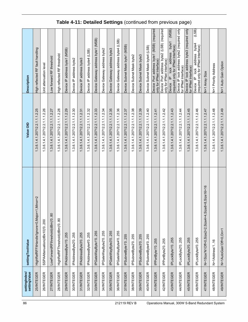
86 212119 REV B Operations Manual, 300W S-Band Redundant System
Table 4-11: Detailed Settings (continued from previous page) se
tting
Inde
x/
setti
ngVa
lue
setti
ngTe
xtVa
lue
Valu
e O
ID
Des
crip
tion
29/IN
TEG
ER
IP
Add
ress
Byt
e1'0
..255
1.
3.6.
1.4.
1.20
712.
2.1.
1.1.
2.29
D
evic
e IP
add
ress
byt
e1 (M
SB
)
30/IN
TEG
ER
IP
Add
ress
Byt
e2'0
..255
1.
3.6.
1.4.
1.20
712.
2.1.
1.1.
2.30
D
evic
e IP
add
ress
byt
e2
31/IN
TEG
ER
IP
Add
ress
Byt
e3'0
..255
1.
3.6.
1.4.
1.20
712.
2.1.
1.1.
2.31
D
evic
e IP
add
ress
byt
e3
32/IN
TEG
ER
IP
Add
ress
Byt
e4'0
..255
1.
3.6.
1.4.
1.20
712.
2.1.
1.1.
2.32
D
evic
e IP
add
ress
byt
e4 (L
SB
)
33/IN
TEG
ER
IP
Gat
eWay
Byt
e1'0
..255
1.
3.6.
1.4.
1.20
712.
2.1.
1.1.
2.33
D
evic
e G
atew
ay a
ddre
ss b
yte1
(MS
B)
34/IN
TEG
ER
IP
Gat
eWay
Byt
e2'0
..255
1.
3.6.
1.4.
1.20
712.
2.1.
1.1.
2.34
D
evic
e G
atew
ay a
ddre
ss b
yte2
35/IN
TEG
ER
IP
Gat
eWay
Byt
e3'0
..255
1.
3.6.
1.4.
1.20
712.
2.1.
1.1.
2.35
D
evic
e G
atew
ay a
ddre
ss b
yte3
36/IN
TEG
ER
IP
Gat
eWay
Byt
e4'0
..255
1.
3.6.
1.4.
1.20
712.
2.1.
1.1.
2.36
D
evic
e G
atew
ay a
ddre
ss b
yte4
(LS
B)
37/IN
TEG
ER
IP
Sub
netB
yte1
'0..2
55
1.3.
6.1.
4.1.
2071
2.2.
1.1.
1.2.
37
Dev
ice
Sub
net M
ask
byte
1 (M
SB
)
38/IN
TEG
ER
IP
Sub
netB
yte2
'0..2
55
1.3.
6.1.
4.1.
2071
2.2.
1.1.
1.2.
38
Dev
ice
Sub
net M
ask
byte
2
39/IN
TEG
ER
IP
Sub
netB
yte3
'0..2
55
1.3.
6.1.
4.1.
2071
2.2.
1.1.
1.2.
39
Dev
ice
Sub
net M
ask
byte
3
40/IN
TEG
ER
IP
Sub
netB
yte4
'0..2
55
1.3.
6.1.
4.1.
2071
2.2.
1.1.
1.2.
40
Dev
ice
Sub
net M
ask
byte
4 (L
SB
)
41/IN
TEG
ER
IP
Por
tByt
e1'0
..255
1.
3.6.
1.4.
1.20
712.
2.1.
1.1.
2.41
D
evic
e P
ort
addr
ess
byte
1 (M
SB
) (r
equi
red
only
for I
PN
et In
terfa
ce)
42/IN
TEG
ER
IP
Por
tByt
e2'0
..255
1.
3.6.
1.4.
1.20
712.
2.1.
1.1.
2.42
D
evic
e P
ort
addr
ess
byte
2 (L
SB
) (r
equi
red
only
for I
PN
et In
terfa
ce)
43/IN
TEG
ER
IP
Lock
Byt
e1'0
..255
1.
3.6.
1.4.
1.20
712.
2.1.
1.1.
2.43
D
evic
e IP
lo
ck
addr
ess
byte
1 (M
SB
) (r
equi
red
only
for I
PN
et In
terfa
ce)
44/IN
TEG
ER
IP
Lock
Byt
e2'0
..255
1.
3.6.
1.4.
1.20
712.
2.1.
1.1.
2.44
D
evic
e IP
lock
add
ress
byt
e2 (
requ
ired
only
fo
r IP
Net
Inte
rface
)
45/IN
TEG
ER
IP
Lock
Byt
e3'0
..255
1.
3.6.
1.4.
1.20
712.
2.1.
1.1.
2.45
D
evic
e IP
lock
add
ress
byt
e3 (
requ
ired
only
fo
r IP
Net
Inte
rface
)
46/IN
TEG
ER
IP
Lock
Byt
e4'0
..255
1.
3.6.
1.4.
1.20
712.
2.1.
1.1.
2.46
D
evic
e IP
lo
ck
addr
ess
byte
4
(LS
B)
(req
uire
d on
ly fo
r IP
Net
Inte
rface
)
27/IN
TEG
ER
Lo
wFo
rwar
dRFt
hres
hold
(dB
m)'0
..80
1.3.
6.1.
4.1.
2071
2.2.
1.1.
1.2.
27
Low
forw
ard
RF
thre
shol
d
28/IN
TEG
ER
H
ighR
efR
FThr
esho
ld(d
Bm
)'0..8
0 1.
3.6.
1.4.
1.20
712.
2.1.
1.1.
2.28
H
igh
refle
cted
RF
thre
shol
d
25/IN
TEG
ER
H
ighR
efR
FFltH
andl
e'Ig
nore
=0,M
ajor
=1,M
inor
=2
1.3.
6.1.
4.1.
2071
2.2.
1.1.
1.2.
25
Hig
h re
flect
ed R
F fa
ult h
andl
ing
26/IN
TEG
ER
S
SP
AA
ttenu
atio
n(dB
x10)
'0..2
00
1.3.
6.1.
4.1.
2071
2.2.
1.1.
1.2.
26
Uni
t atte
nuat
ion
leve
l
47/IN
TEG
ER
N
+1S
ize’
N1O
ff=0,
Siz
e2=2
,Siz
e4=4
,Siz
e8=8
,Siz
e16=
16
1.3.
6.1.
4.1.
2071
2.2.
1.1.
1.2.
47
N+1
Arra
y S
ize
48/IN
TEG
ER
N
+1A
ddre
ss’1
..16
1.3.
6.1.
4.1.
2071
2.2.
1.1.
1.2.
48
N+1
Prio
rity
Add
ress
49/IN
TEG
ER
N
+1A
utoG
ain’
Off=
0,O
n=1
1.3.
6.1.
4.1.
2071
2.2.
1.1.
1.2.
49
N+1
Aut
o G
ain
Opt
ion
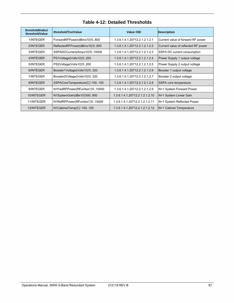
Operations Manual, 300W S-Band Redundant System 212119 REV B 87
thresholdIndex/ thresholdValue thresholdTextValue Value OID Description
1/INTEGER ForwardRFPower(dBmx10)'0..800 1.3.6.1.4.1.20712.2.1.2.1.2.1 Current value of forward RF power
2/INTEGER ReflectedRFPower(dBmx10)'0..800 1.3.6.1.4.1.20712.2.1.2.1.2.2 Current value of reflected RF power
3/INTEGER SSPADCCurrent(Ampx10)'0..10000 1.3.6.1.4.1.20712.2.1.2.1.2.3 SSPA DC current consumption
4/INTEGER PS1Voltage(Voltx10)'0..200 1.3.6.1.4.1.20712.2.1.2.1.2.4 Power Supply 1 output voltage
5/INTEGER PS2Voltage(Voltx10)'0..200 1.3.6.1.4.1.20712.2.1.2.1.2.5 Power Supply 2 output voltage
6/INTEGER Booster1Voltage(Voltx10)'0..320 1.3.6.1.4.1.20712.2.1.2.1.2.6 Booster 1 output voltage
7/INTEGER Booster2Voltage(Voltx10)'0..320 1.3.6.1.4.1.20712.2.1.2.1.2.7 Booster 2 output voltage
8/INTEGER SSPACoreTemperature(C)'-100..100 1.3.6.1.4.1.20712.2.1.2.1.2.8 SSPA core temperature
Table 4-12: Detailed Thresholds
9/INTEGER N1FwdRFPower(RFunitsx1)'0..10000 1.3.6.1.4.1.20712.2.1.2.1.2.9 N+1 System Forward Power
10/INTEGER N1SystemGain(dBx10)'500..900 1.3.6.1.4.1.20712.2.1.2.1.2.10 N+1 System Linear Gain
11/INTEGER N1RefRFPower(RFunitsx1)'0..10000 1.3.6.1.4.1.20712.2.1.2.1.2.11 N+1 System Reflected Power
12/INTEGER N1CabinetTemp(C)’-100..100 1.3.6.1.4.1.20712.2.1.2.1.2.12 N+1 Cabinet Temperature
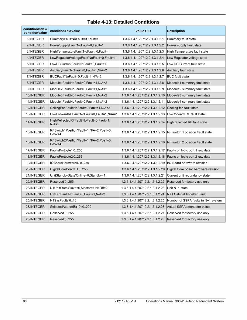
88 212119 REV B Operations Manual, 300W S-Band Redundant System
conditionIndex/ conditionValue conditionTextValue Value OID Description
1/INTEGER SummaryFault'NoFault=0,Fault=1 1.3.6.1.4.1.20712.2.1.3.1.2.1 Summary fault state
2/INTEGER PowerSupplyFault'NoFault=0,Fault=1 1.3.6.1.4.1.20712.2.1.3.1.2.2 Power supply fault state
3/INTEGER HighTemperatureFault'NoFault=0,Fault=1 1.3.6.1.4.1.20712.2.1.3.1.2.3 High Temperature fault state
4/INTEGER LowRegulatorVoltageFault'NoFault=0,Fault=1 1.3.6.1.4.1.20712.2.1.3.1.2.4 Low Regulator voltage state
5/INTEGER LowDCCurrentFault'NoFault=0,Fault=1 1.3.6.1.4.1.20712.2.1.3.1.2.5 Low DC Current fault state
6/INTEGER AuxiliaryFault'NoFault=0,Fault=1,N/A=2 1.3.6.1.4.1.20712.2.1.3.1.2.6 Auxiliary fault state
7/INTEGER BUCFault'NoFault=0,Fault=1,N/A=2 1.3.6.1.4.1.20712.2.1.3.1.2.7 BUC fault state
8/INTEGER Module1Fault'NoFault=0,Fault=1,N/A=2 1.3.6.1.4.1.20712.2.1.3.1.2.8 Modeule1 summary fault state
9/INTEGER Module2Fault'NoFault=0,Fault=1,N/A=2 1.3.6.1.4.1.20712.2.1.3.1.2.9 Modeule2 summary fault state
10/INTEGER Module3Fault'NoFault=0,Fault=1,N/A=2 1.3.6.1.4.1.20712.2.1.3.1.2.10 Modeule3 summary fault state
11/INTEGER Module4Fault'NoFault=0,Fault=1,N/A=2 1.3.6.1.4.1.20712.2.1.3.1.2.11 Modeule4 summary fault state
12/INTEGER CollingFanFault'NoFault=0,Fault=1,N/A=2 1.3.6.1.4.1.20712.2.1.3.1.2.12 Cooling fan fault state
13/INTEGER LowForwardRFFault'NoFault=0,Fault=1,N/A=2 1.3.6.1.4.1.20712.2.1.3.1.2.13 Low forward RF fault state
14/INTEGER HighReflectedRFFault'NoFault=0,Fault=1, N/A=2 1.3.6.1.4.1.20712.2.1.3.1.2.14 High reflected RF fault state
15/INTEGER RFSwitch1Position'Fault=1,N/A=2,Pos1=3, Pos2=4 1.3.6.1.4.1.20712.2.1.3.1.2.15 RF switch 1 position /fault state
16/INTEGER RFSwitch2Position'Fault=1,N/A=2,Pos1=3, Pos2=4 1.3.6.1.4.1.20712.2.1.3.1.2.16 RF switch 2 position /fault state
17/INTEGER FaultsPortbyte1'0..255 1.3.6.1.4.1.20712.2.1.3.1.2.17 Faults on logic port 1 raw data
18/INTEGER FaultsPortbyte2'0..255 1.3.6.1.4.1.20712.2.1.3.1.2.18 Faults on logic port 2 raw data
19/INTEGER IOBoardHardwareID'0..255 1.3.6.1.4.1.20712.2.1.3.1.2.19 I/O Board hardware revision
20/INTEGER DigitalCoreBoardID'0..255 1.3.6.1.4.1.20712.2.1.3.1.2.20 Digital Core board hardware revision
21/INTEGER UnitStandbyState'Online=0,Standby=1 1.3.6.1.4.1.20712.2.1.3.1.2.21 Current unit redundancy state
Table 4-13: Detailed Conditions
22/INTEGER Reserved’0..255 1.3.6.1.4.1.20712.2.1.3.1.2.22 Reserved for factory use only
23/INTEGER N1UnitState’Slave=0,Master=1,N1Off=2 1.3.6.1.4.1.20712.2.1.3.1.2.23 Unit N+1 state
24/INTEGER ExtFanFault’NoFault=0,Fault=1,N/A=2 1.3.6.1.4.1.20712.2.1.3.1.2.24 N+1 Cabinet Impeller Fault
25/INTEGER N1SysFaults’0..16 1.3.6.1.4.1.20712.2.1.3.1.2.25 Number of SSPA faults in N+1 system
26/INTEGER SelectedAtten(dBx10)’0,,200 1.3.6.1.4.1.20712.2.1.3.1.2.26 Actual SSPA attenuator value
27/INTEGER Reserved’0..255 1.3.6.1.4.1.20712.2.1.3.1.2.27 Reserved for factory use only
28/INTEGER Reserved’0..255 1.3.6.1.4.1.20712.2.1.3.1.2.28 Reserved for factory use only

Operations Manual, 300W S-Band Redundant System 212119 REV B 89
4.6.2.5 Connecting to a MIB browser For a MIB browser application example, we will be using the freeware browser GetIf, version 2.3.1. There are many other browsers available for download from http://www.snmplink.org/Tools.html.
1. Copy the provided Paradise Datacom LLC MIB file into the Getif Mibs subfolder. 2. Start the GetIf application. 3. Select the unit IP address and community strings in the relevant text boxes on the
Parameters tab (see Figure 4-12) and then click the Start button.
4. Select the MIBBrowser tab. 5. Click on ‘iso main entity’ on the MIB tree, then click the Start button. 6. See update data in output data box (Figure 4-13).
Figure 4-12: GetIF Application Parameters Tab
Figure 4-13: Getif MBrowser window, with update data in output data box

90 212119 REV B Operations Manual, 300W S-Band Redundant System
7. Select settingValue.5 entity (SSPA Mute), set the value to 1 and click the Set button.
8. Observe the Mute state on the SSPA change to a “Mute On” state. See Figure 4-14.
Figure 4-14: Getif MBrowser window, setting settingValue.5 to a value of ‘1’

Operations Manual, 300W S-Band Redundant System 212119 REV B 91
Section 5: Troubleshooting
5.0 Troubleshooting Faults The Rack Mount SSPA has five fault condition LEDs on left side of the front panel which reflect a summary fault, and fault states for voltage, temperature, current and the amplifier’s power supply. Additional fault reporting is available via the front panel display readout. Figure 3-1 shows a representation of the fault condition indicators. The following sections describe steps the user should take to determine the cause of a fault state in a stand-alone amplifier. 5.0.1 Summary Fault Any of the following faults also results in a summary fault state. 5.0.2 Voltage Fault The user should check the voltages displayed on page 6 of the system information menu of the front panel display. If the voltages are outside of the normal output ranges as described in Section 2.2.1.6, consult the factory. 5.0.3 Temperature Fault If you are experiencing a temperature fault, follow the steps below:
• Check the ambient are temperature of the room where the SSPA is installed. Check the environmental specifications on the specification sheet for your SSPA. If the ambient temperature is beyond these limits, the unit may experience a tem-perature fault. If this is the case, action will need to be taken by the operator to bring the ambient temperature into the specified range.
• If the ambient temperature is within the specified range and the unit experiences a temperature fault, the operator should perform a visual inspection of the fans to make sure they are all spinning.
• The user should check the front panel read-out out for a fan fault. This can be found under the system information portion of the Main Menu on the front panel. If a fan fault is present, the user may need to replace the fan that is not functioning.
• The operator should check the booster board voltages on the front panel display. This can be found under the system information portion of the Main Menu on the front panel. The voltage should read approximately 28 VDC for each of the fans in the SSPA. If the booster voltage is lower than 25 VDC, the operator should check for a power supply fault and follow the procedures to handle this problem.
Figure 5-1: Front panel
Fault display

92 212119 REV B Operations Manual, 300W S-Band Redundant System
5.0.4 Current Fault In the case of a current fault, follow the tips below:
• The user should check the current displayed on Page 6 of the system information menu of the front panel display. If the amplifier is in the mute state, current drops within a range of 0 to 5 A.
5.0.5 Power Supply Fault In the case of a power supply fault, follow the steps below:
• Check the power supply readings on the SSPA front panel. Observe any fluctua-tions and record the level.
• Mute the amplifier. Check the power supply readings on the SSPA front panel. Sometimes muting the amplifier corrects the power supply fault.
5.0.6 Fan Fault In the case of a fan fault, follow the tips below:
• Inspect the fans. • Check the booster board voltages on the front panel display. This information can
be found under the system information portion of the Main Menu. The voltage should read approximately 28 VDC for each of the fans in the SSPA.
• If necessary, replace the fan (See Section 7.1.1). 5.0.7 Low RF Fault In the case of a Low RF alarm, follow the steps below.
• Check the forward RF level on the front panel readout under the system information menu. If the user has access to a power meter or spectrum analyzer, this power level can be verified by means of the output sample port on the front panel.
• Compare this value to the forward RF alarm threshold level in the Fault Set-up menu. If the Threshold level is higher than the actual RF output level, this will pro-duce a low RF alarm, providing that the low RF alarm option is enabled.
• At this point, be sure that the forward RF alarm threshold level is set to a value corresponding to the desired output level for the SSPA in question. The factory pre-set for this value is always 10 dBm below the specified P1db compression point of the SSPA. However, you may wish to set this level closer to the desired output level in order to catch any minor fluctuations below the set level. If the level is set too high, the low RF alarm may be displayed when there are no legitimate problems. If the RF input signal has been lowered, this will also lower the output of the SSPA and may cause a low RF alarm.

Operations Manual, 300W S-Band Redundant System 212119 REV B 93
• If the user is certain that the amplifier is in an alarmed state due to problems other than the ones stated above, the user should verify that no other fault conditions are present. If a power supply fault, current fault, or voltage fault is present, this may also cause the low RF alarm to show. If any of these is the case, the user should refer to the sections corresponding to that specific fault.
5.1 Modular SSPA Architecture The Teledyne Paradise Datacom SSPA Chassis consists of a modular design, which allows for quick and easy maintenance and replacement in the event of a catastrophic failure of one of the SSPA components. 5.1.1 Removable Fan Assembly The air intake fan assembly can be easily replaced without interruption of service. Replace-ment fans are available from Teledyne Paradise Datacom. The front panel (intake) fan tray is secured by four captive thumb screws. To remove, loosen the screws and carefully remove the fan tray from the chassis. See Figure 5-2. Unplug the fan power cord from the connector at the top right of the plenum to fully remove the fan plate assembly. See Figure 5-3.
Plug the fan power cord of the replacement fan assembly into the power connector. Carefully insert the replacement fan assembly into the enclosure and secure into place by tightening the four captive thumb screws until snug.
Figure 5-2: Unscrew thumb screws on front fan tray and slide the tray from the chassis.
Figure 5-3: To fully remove fan tray, unplug quick connector.

94 212119 REV B Operations Manual, 300W S-Band Redundant System
5.1.1.1 Fan and Heatsink Maintenance It is recommended that the cooling system of the SSPA be checked at least once per month. If the environment in the area where the amplifier is being operated produces a large amount of dust and debris, this check should be performed more frequently. The intake fans of the amplifier can pull airborne debris into the enclosure, and fill the spaces between the heatsink fans. See Figure 5-4. As this debris builds up inside the amplifier, the airflow which is important in cooling the amplifier is impinged.
Blockage of the heatsink will cause the internal temperature of the amplifier module to rise above what is considered as normal operating conditions. While the amplifiers have thermal protection, long periods of elevated temperatures could reduce amplifier life. The front panel menu can be used to check the amplifier base plate temperature. The base plate temperature should normally not exceed 75 °C. To view the SSPA base plate tempera-ture, press the Main Menu key and select 1.SysInfo and press the Enter key; press the Down Arrow (▼) key seven times. If the base plate temperature exceeds 75 °C, it is one indicator that the system’s airflow requires maintenance.0
Note: The amplifier’s temperature alarm threshold is set to 85 °C. If the base plate temperature reaches 85 °C, the front panel Temp Fault LED will activate. If the temperature reaches 90 °C, the amplifier will shut down.
The heatsink fins should be visually inspected for excessive dirt and debris build-up. If it ap-pears there is excessive debris in the fans or heatsink; the fan tray can be removed for easy cleaning.
1. Using a Philips head screw driver, loosen the thumbscrews holding the front fan tray in place.
2. Remove the front panel fan tray. See Figure 5-2. 3. Unplug the fan power cord from the power pole connector. See Figure 5-3. 4. Use the shop vac to collect all dust and debris. 5. Use a can of compressed air to dislodge any dust or debris lodged within the
heatsink fins and the fan assembly. Ensure that the heatsink fins are free from all debris. See Figure 5-5.
Figure 5-4: Example of dust blocking heatsink fins
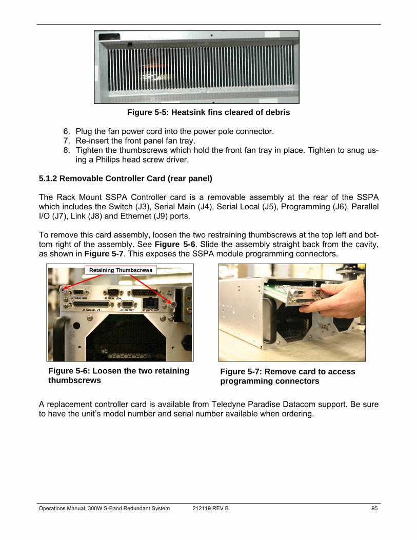
Operations Manual, 300W S-Band Redundant System 212119 REV B 95
6. Plug the fan power cord into the power pole connector. 7. Re-insert the front panel fan tray. 8. Tighten the thumbscrews which hold the front fan tray in place. Tighten to snug us-
ing a Philips head screw driver. 5.1.2 Removable Controller Card (rear panel) The Rack Mount SSPA Controller card is a removable assembly at the rear of the SSPA which includes the Switch (J3), Serial Main (J4), Serial Local (J5), Programming (J6), Parallel I/O (J7), Link (J8) and Ethernet (J9) ports. To remove this card assembly, loosen the two restraining thumbscrews at the top left and bot-tom right of the assembly. See Figure 5-6. Slide the assembly straight back from the cavity, as shown in Figure 5-7. This exposes the SSPA module programming connectors.
A replacement controller card is available from Teledyne Paradise Datacom support. Be sure to have the unit’s model number and serial number available when ordering.
Figure 5-5: Heatsink fins cleared of debris
Figure 5-6: Loosen the two retaining thumbscrews
Figure 5-7: Remove card to access programming connectors
Retaining Thumbscrews
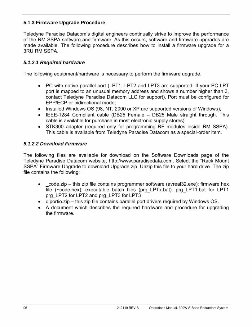
96 212119 REV B Operations Manual, 300W S-Band Redundant System
5.1.3 Firmware Upgrade Procedure Teledyne Paradise Datacom’s digital engineers continually strive to improve the performance of the RM SSPA software and firmware. As this occurs, software and firmware upgrades are made available. The following procedure describes how to install a firmware upgrade for a 3RU RM SSPA. 5.1.2.1 Required hardware The following equipment/hardware is necessary to perform the firmware upgrade.
• PC with native parallel port (LPT1; LPT2 and LPT3 are supported. If your PC LPT port is mapped to an unusual memory address and shows a number higher than 3, contact Teledyne Paradise Datacom LLC for support). Port must be configured for EPP/ECP or bidirectional mode;
• Installed Windows OS (98, NT, 2000 or XP are supported versions of Windows); • IEEE-1284 Compliant cable (DB25 Female – DB25 Male straight through. This
cable is available for purchase in most electronic supply stores). • STK300 adapter (required only for programming RF modules inside RM SSPA).
This cable is available from Teledyne Paradise Datacom as a special-order item. 5.1.2.2 Download Firmware The following files are available for download on the Software Downloads page of the Teledyne Paradise Datacom website, http://www.paradisedata.com. Select the “Rack Mount SSPA” Firmware Upgrade to download Upgrade.zip. Unzip this file to your hard drive. The zip file contains the following:
• _code.zip – this zip file contains programmer software (avreal32.exe); firmware hex file (~code.hex); executable batch files (prg_LPTx.bat). prg_LPT1.bat for LPT1 prg_LPT2 for LPT2 and prg_LPT3 for LPT3
• dlportio.zip – this zip file contains parallel port drivers required by Windows OS. • A document which describes the required hardware and procedure for upgrading
the firmware.

Operations Manual, 300W S-Band Redundant System 212119 REV B 97
5.1.2.3 Step-by Step procedure
1. Unpack dlportio.zip on the target PC. Run Setup.exe to install. After installation is successfully completed, reboot the computer.
2. Unpack _code.zip into a temporary folder (for example - C:\tmp). After the files are unpacked, locate the \_code subfolder.
3. Turn off the SSPA receiving the firmware upgrade. • For RM SSPA Controller Card: Connect PC LPT port to M&C Board J6 Pro-
gram port at the back of the SSPA through an IEEE1284 compliant cable. Turn on the SSPA.
• For RM SSPA RF modules: Remove the controller card assembly as de-scribed in Section 5.1.3. Connect a STK 300 adapter into the module’s pro-gramming connector. Connect an IEEE1284 cable between the PC LPT port and the STK 300 DB25 adapter. Turn on the unit’s power. Repeat the pro-gramming procedure for all available modules inside a RM SSPA. Refer to Figures 5-6, 5-7, 5-8 and 5-9 for details.
4. In the \_code subfolder, locate the batch file which suits your LPT port designation (For example: prg_LPT1.bat for LPT1 parallel port) and run it. The batch file will open a Command prompt console window and execute the firmware update. Do not interfere with the program until the entire process is complete. An example screenshot is shown in Figure 3-14 on the following page.
5. There is a possibility of encountering problems during the firmware upload. Not all LPT ports automatically get high priority service from Windows OS. If a problem occurs during the verification process, simply shut down the console windows by pressing Ctrl-C buttons on the keyboard. Repeat the update process starting from Step ‘d’ of this procedure. It may take two or three attempts.
6. Replace the RM SSPA Controller Card assembly into the bay, and secure with the restraining thumbscrews.
Module 1 Module 2
Figure 5-8: 3RU Rack Mount SSPAs have two module programming connectors
Figure 5-9: Insert adapter tail into module programming connector

98 212119 REV B Operations Manual, 300W S-Band Redundant System
THIS PAGE LEFT INTENTIONALLY BLANK

Operations Manual, 300W S-Band Redundant System 212119 REV B 99
This section describes the procedure for setting up the RM SSPA Ethernet IP interface through the front panel interface. It also describes basic network setup of a Windows based host PC for a peer-to-peer network connection with the RM SSPA. Important! Do not use a crossover cable to connect to the network hub, use crossover only for direct PC-to-RM SSPA connection! 1. Connect J6 Ethernet Port of the RM SSPA controller to a host PC through a crossover null-modem network cable (see Appendix B) for wiring details. 2. If the PC NIC card has not previously been set, do so now using the following procedure, otherwise skip to Step 3. 2.1 From Windows Control Panel select Network icon; 2.2 Select TCP/IP properties of your LAN card. A window similar to that shown in Figure A-1 will appear:
2.3 Select "Specify an IP Address". And enter the following parameters in the IP address and Subnet fields: IP Address……………:192.168.0.3 Subnet Mask………….:255.255.255.0 After you press the “OK” button, depending on the operating system, you may need to reboot the workstation.
Appendix A: Ethernet Interface Quick Set-up
Figure A-1: TCP/IP Properties Window

100 212119 REV B Operations Manual, 300W S-Band Redundant System
2.4 After the optional reboot, open the Command Prompt console window and enter:
C:\>IPCONFIG This will display the IP settings:
0 Ethernet Adapter: IP Address: 192.168.0.3 Subnet Mask: 255.255.255.0 Default Gateway:
2.5 You can now try to Ping your PC: In Command Prompt window enter the following:
C:\>ping 192.168.0.3 This will display:
Pinging 192.168.0.3 with 32 bytes of data: Reply from 192.168.0.3: bytes=32 time<10ms TTL=128 Reply from 192.168.0.3: bytes=32 time<10ms TTL=128 Reply from 192.168.0.3: bytes=32 time<10ms TTL=128 Reply from 192.168.0.3: bytes=32 time<10ms TTL=128 Ping statistics for 192.168.0.3: Packets: Sent=4, Received=4, Lost=0 (0%loss), Approximate round trip times I milli-seconds: Minimum=0ms, Maximum=0ms, Average=0ms
Your network LAN card is now set up. 3. On the RM SSPA unit front panel, perform the following sequence: Press the Main Menu key; select 2.Com.Setup and press the Enter key; select 5.IPSetup and press the Enter key; select 2.LocalIP and press the Enter key. Use the front panel navi-gation keys to select address “192.168.0.0” and press the Enter key. Follow the same menu route to select the Subnet, Gateway, IPPort and IPLock items, and set those parameters to: Subnet:255.255.255.0; Gateway:0.0.0.0; IPLock:255.255.255.255; IPPort:1038. Verify the selected parameters by following the menu path listed above and selecting 1.IPInfo and pressing the Enter key.

Operations Manual, 300W S-Band Redundant System 212119 REV B 101
4. On the RM SSPA unit front panel, perform the following sequence: Press the Main Menu key; select 2.Com.Setup and press the Enter key; select 4.Interfc and press the Enter key; select 3.IPNet and press the Enter key. The RM SSPA is now set up to work with Ethernet Interface. You may now ping the SSPA unit from host PC:
C:\>ping 192.168.0.0 This will display:
Pinging 192.168.0.0 with 32 bytes of data: Reply from 192.168.0.0: bytes=32 time<10ms TTL=128 Reply from 192.168.0.0: bytes=32 time<10ms TTL=128 Reply from 192.168.0.0: bytes=32 time<10ms TTL=128 Reply from 192.168.0.0: bytes=32 time<10ms TTL=128 Ping statistics for 192.168.0.3: Packets: Sent=4, Received=4, Lost=0 (0%loss), Approximate round trip times I milli-seconds: Minimum=0ms, Maximum=0ms, Average=0ms
5. Load the Paradise Datacom Universal M&C package on the host PC, and launch it to check all M&C functions. Refer to Appendix C for details. When prompted, select an Internet connection to the unit using IP Address 192.168.0.0, local port address 1039 and remote port address 1038. The SSPA now connected to your host workstation for remote M&C.

102 212119 REV B Operations Manual, 300W S-Band Redundant System
THIS PAGE LEFT INTENTIONALLY BLANK

Operations Manual, 300W S-Band Redundant System 212119 REV B 103
Appendix B: Proper 10/100 Base-T Ethernet Cable Wiring
This section briefly describes the basic theory related to the physical layer of 10/100 Base-T networking, as well as proper wiring techniques. There are several classifications of cable used for twisted-pair networks. Recommended ca-ble for all new installations is Category 5 (or CAT 5). CAT 5 cable has four twisted pairs of wire for a total of eight individually insulated wires. Each pair is color coded with one wire hav-ing a solid color (blue, orange, green, or brown) twisted around a second wire with a white background and a stripe of the same color. The solid colors may have a white stripe in some cables. Cable colors are commonly described using the background color followed by the color of the stripe; e.g., white-orange is a cable with a white background and an orange stripe. The straight through and crossover patch cables are terminated with CAT 5 RJ-45 modular plugs. RJ-45 plugs are similar to those you'll see on the end of your telephone cable except they have eight versus four or six contacts on the end of the plug and they are about twice as big. Make sure they are rated for CAT 5 wiring. (RJ means "Registered Jack"). A special Modular Plug Crimping Tool (such as that shown in Figure B-1) is needed for proper wiring.
The 10BASE-T and 100BASE-TX Ethernets consist of two transmission lines. Each transmis-sion line is a pair of twisted wires. One pair receives data signals and the other pair transmits data signals. A balanced line driver or transmitter is at one end of one of these lines and a line receiver is at the other end. A simplified schematic for one of these lines and its transmit-ter and receiver is shown in Figure B-2.
Figure B-1: Modular Plug Crimping Tool
Figure B-2: Transmission Line
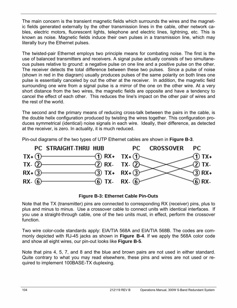
104 212119 REV B Operations Manual, 300W S-Band Redundant System
The main concern is the transient magnetic fields which surrounds the wires and the magnet-ic fields generated externally by the other transmission lines in the cable, other network ca-bles, electric motors, fluorescent lights, telephone and electric lines, lightning, etc. This is known as noise. Magnetic fields induce their own pulses in a transmission line, which may literally bury the Ethernet pulses. The twisted-pair Ethernet employs two principle means for combating noise. The first is the use of balanced transmitters and receivers. A signal pulse actually consists of two simultane-ous pulses relative to ground: a negative pulse on one line and a positive pulse on the other. The receiver detects the total difference between these two pulses. Since a pulse of noise (shown in red in the diagram) usually produces pulses of the same polarity on both lines one pulse is essentially canceled by out the other at the receiver. In addition, the magnetic field surrounding one wire from a signal pulse is a mirror of the one on the other wire. At a very short distance from the two wires, the magnetic fields are opposite and have a tendency to cancel the effect of each other. This reduces the line's impact on the other pair of wires and the rest of the world. The second and the primary means of reducing cross-talk between the pairs in the cable, is the double helix configuration produced by twisting the wires together. This configuration pro-duces symmetrical (identical) noise signals in each wire. Ideally, their difference, as detected at the receiver, is zero. In actuality, it is much reduced. Pin-out diagrams of the two types of UTP Ethernet cables are shown in Figure B-3.
Note that the TX (transmitter) pins are connected to corresponding RX (receiver) pins, plus to plus and minus to minus. Use a crossover cable to connect units with identical interfaces. If you use a straight-through cable, one of the two units must, in effect, perform the crossover function. Two wire color-code standards apply: EIA/TIA 568A and EIA/TIA 568B. The codes are com-monly depicted with RJ-45 jacks as shown in Figure B-4. If we apply the 568A color code and show all eight wires, our pin-out looks like Figure B-5. Note that pins 4, 5, 7, and 8 and the blue and brown pairs are not used in either standard. Quite contrary to what you may read elsewhere, these pins and wires are not used or re-quired to implement 100BASE-TX duplexing.
Figure B-3: Ethernet Cable Pin-Outs

Operations Manual, 300W S-Band Redundant System 212119 REV B 105
There are only two unique cable ends in the preceding diagrams, they correspond to the 568A and 568B RJ-45 jacks and are shown in Figure B-6.
Figure B-4: Ethernet Wire Color Code Standards
Figure B-5: Wiring Using 568A Color Codes
Figure B-6: Wiring Using 568A and 568B Color Codes
568A CABLE END
568B CABLE END
106 212119 REV B Operations Manual, 300W S-Band Redundant System
Again, the wires with colored backgrounds may have white stripes and may be denoted that way in diagrams found elsewhere. For example, the green wire may be labeled Green-White. The background color is always specified first. Now, all you need to remember, to properly configure the cables, are the diagrams for the two cable ends and the following rules:
• A straight-thru cable has identical ends. • A crossover cable has different ends.
It makes no functional difference which standard you use for a straight-thru cable. You can start a crossover cable with either standard as long as the other end is the other standard. It makes no functional difference which end is which. A 568A patch cable will work in a network with 568B wiring and a 568B patch cable will work in a 568A network. Here are some essential cabling rules:
1. Try to avoid running cables parallel to power cables. 2. Do not bend cables to less than four times the diameter of the cable. 3. If you bundle a group of cables together with cable ties (zip ties), do not over-cinch
them. It's okay to snug them together firmly; but don't tighten them so much that you deform the cables.
4. Keep cables away from devices which can introduce noise into them, such as: copy machines, electric heaters, speakers, printers, TV sets, fluorescent lights, copiers, welding machines, microwave ovens, telephones, fans, elevators, motors, electric ovens, dryers, washing machines, and shop equipment.
5. Avoid stretching UTP cables (tension when pulling cables should not exceed 25 LBS).
6. Do not run UTP cable outside of a building. It presents a very dangerous lightning hazard!
7. Do not use a stapler to secure UTP cables. Use telephone wire/RG-6 coaxial wire hangers, which are available at most hardware stores.
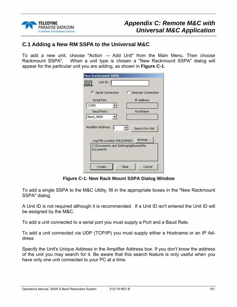
Operations Manual, 300W S-Band Redundant System 212119 REV B 107
Appendix C: Remote M&C with Universal M&C Application
C.1 Adding a New RM SSPA to the Universal M&C To add a new unit, choose "Action → Add Unit" from the Main Menu. Then choose Rackmount SSPA". When a unit type is chosen a "New Rackmount SSPA" dialog will appear for the particular unit you are adding, as shown in Figure C-1.
To add a single SSPA to the M&C Utility, fill in the appropriate boxes in the "New Rackmount SSPA" dialog. A Unit ID is not required although it is recommended. If a Unit ID isn't entered the Unit ID will be assigned by the M&C. To add a unit connected to a serial port you must supply a Port and a Baud Rate. To add a unit connected via UDP (TCP/IP) you must supply either a Hostname or an IP Ad-dress Specify the Unit's Unique Address in the Amplifier Address box. If you don't know the address of the unit you may search for it. Be aware that this search feature is only useful when you have only one unit connected to your PC at a time.
Figure C-1: New Rack Mount SSPA Dialog Window

108 212119 REV B Operations Manual, 300W S-Band Redundant System
Choose a log file location by clicking the [Browse…] button. The default is the “My Docu-ments” folder. The log file name will be the UnitID and the extension “.log” appended to it. i.e. “Unit1.log”. C.2 Rack mount SSPA overview for the Universal M&C Each Rack Mount SSPA in the M&C has four screens. The first screen is the “status” screen shown in Figure C-2. The status screen reflects the current conditions (or state) of the Rack Mount SSPA. In addition, the status screen allows for Mute/Unmute of the carrier and manual adjustment of the on-board Attenuator for gain control.
The second screen is the “faults” screen, shown in Figure C-3. It shows the user the status of all faults on-board the Rack Mount SSPA. Each RF Module in the SSPA is monitored for faults in addition to the SSPA itself. If a module is not installed in the SSPA, say Module 3 is not in a 2 module SSPA, then it will show up as N/A or Ignore in the Module Status box.
Figure C-2: SSPA Status Window
Figure C-3: SSPA Faults Window

Operations Manual, 300W S-Band Redundant System 212119 REV B 109
The third screen is the "settings" screen, shown in Figure C-4. It shows the user all available settings on the Rack Mount SSPA. All user-adjustable settings are allowed to be modified to suit the specific needs of the customer. However, it should be noted that the Rack Mount SSPA is configured for the customer at the factory. If modification of any settings is necessary please refer to the Rack Mount SSPA Manual.
The fourth screen is the "IP Setup" screen, shown in Figure C-5. It shows the user all of the TCP/IP settings on the Rack Mount SSPA. When the IP Address is modified the SSPA must be reset for it to use the new IP Address. Until the SSPA is reset it will use the old IP Address. The Amplifier Local Port is the port that the SSPA listens to for UDP requests. The SSPA also answers requests using the same port. If the Amplifier Local Port is changed the SSPA must be reset. The Gateway Address and Subnet Mask are standard settings for TCPI/IP commu-nications. If either of these settings is changed the SSPA must be reset for the new settings to take effect. The IP Lock Address is used for security. If it is set to something besides 0.0.0.0 or 255.255.255.255 it will only answer the address it is set to. For example, if the IP Lock Address is 192.168.0.50 then a request from 192.168.0.100 will not be accepted. The IP Lock Address may be changed without resetting the SSPA.
Figure C-4: SSPA Settings Window
Figure C-5: IP Setup Window

110 212119 REV B Operations Manual, 300W S-Band Redundant System
THIS PAGE LEFT INTENTIONALLY BLANK
Operations Manual, 300W S-Band Redundant System 212119 REV B 111
The following pages comprise the documentation package for the CRM Series of Teledyne Paradise Datacom Rack Mount Solid State Power Amplifiers. This package consists of: Specification Sheet: 204464 (check our web site http://www.paradisedata.com for the most recent version of this document); Outline Drawing, specific to your system; Block Diagram, specific to your system; and Schematic, specific to your system.
Appendix D: Documentation

112 212119 REV B Operations Manual, 300W S-Band Redundant System
THIS PAGE LEFT INTENTIONALLY BLANK