10K98MC-C and 6S35MC on the same Testbed and 6S35MC on the same Testbed L/74236-1.0/0402 (3000/OG)...
25
© MAN Diesel A/S SVH / R&D Dept 2431 Basic Research & Emission 1 10K98MC-C and 6S35MC on the same Testbed L/74236-1.0/0402 (3000/OG)
Transcript of 10K98MC-C and 6S35MC on the same Testbed and 6S35MC on the same Testbed L/74236-1.0/0402 (3000/OG)...

© MAN Diesel A/SSVH / R&D Dept 2431 Basic Research & Emission 1
10K98MC-C and 6S35MC on the
same Testbed
L/74236-1.0/0402 (3000/OG)

© MAN Diesel A/SSVH / R&D Dept 2431 Basic Research & Emission 2
Low-Sulfur-Fuel
Standard Operating Procedures
for MAN B&W Engines
Svend Henningsen
MD-C, R&D, Process Development, Emission
San Pedro Bay Ports Vessel Fuel Incentive
Program Workshop – May 21, 2008

© MAN Diesel A/SSVH / R&D Dept 2431 Basic Research & Emission 3
Background:
The fuel specification will change in the future
due to Legislation requirements
Low-Sulfur HFO or Distillates will be used in
near coastal areas
Goal:
Safe operation of the engine with easy
maintenance and low operation costs
Low-Sulfur-Fuel
Standard Operating Procedures

© MAN Diesel A/SSVH / R&D Dept 2431 Basic Research & Emission 4
Incompatibility of fuels
Ignition and combustion characteristics
Lower fuel viscosity, flash point & increased
level of cat fines
Matching of low-Sulfur fuel, cylinder lube-oil BN
and cylinder lube-oil feed rate
Fuel change-over procedures
Fuel and cylinder lube-oil systems
What to look out for

© MAN Diesel A/SSVH / R&D Dept 2431 Basic Research & Emission 5
Incompatibility of fuels
2100/KEA/BRO
When switching from HFO to a distillate fuel with
low aromatic hydrocarbon there is a risk of
incompatibility
The asphaltenes of the HFO are likely to
precipitate as heavy sludge with clogging filters as
result
Use of test compatibility kit on board or guarantee
from fuel supplier that fuels used can be blended

© MAN Diesel A/SSVH / R&D Dept 2431 Basic Research & Emission 6
Ignition characteristic
FIA – 100 FCA: Constant volume spray combustion chamber with
Tinit = 800K and Pinit = 45bar
Pressure trace Heat release rate

© MAN Diesel A/SSVH / R&D Dept 2431 Basic Research & Emission 7
Viscosity of Marine Fuels
3332013.2004.11.05 (2100/KEA)
1
10
100
1000
10000
100000
-15 35 85 135
Temperature Degrees Celsius
Kinematic Viscosity
Marine Gas Oil
Marine Diesel Oil
IF-30
IF-60
IF-100
IF-180
IF-380
MBD limitmin. 2 cst

© MAN Diesel A/SSVH / R&D Dept 2431 Basic Research & Emission 8
CIMAC, Oslo 25th January 2006 Henrik Rolsted
Optimizing the Cylinder Condition– Lubrication versus Maintenance
Liner wear rate as function of lube dosage
0
0.1
0.2
0.3
0.4
0.5
0.6
0.7
0.8
0.9
1
0.3 0.4 0.5 0.6 0.7 0.8 0.9 1 1.1 1.2 1.3 1.4 1.5 1.6
lube dosage (g/bhph)
Lin
er
wear
(mm
/1000h
)
0.10 mm/1000h
0.05 mm/1000h
0.02 mm/1000h

© MAN Diesel A/SSVH / R&D Dept 2431 Basic Research & Emission 9
Comparison of Sulphur Content and
Lube-Oil TBN
Cylinder wear
mm/1000 hBN40 BN70
0,4
0,3
0,2
0,1
00
Cylinder wear for equal cylinder-oil feed rates
1 2 3 4 5 6 7L/71510-0.1/0301 2160/KEA) Sulphur %

© MAN Diesel A/SSVH / R&D Dept 2431 Basic Research & Emission 10
3333011.2005.09.05 (2160/KEA)
Use of BN40 Cylinder oil feed rates
Low S fuel, Alpha ACC
The correlation between fuel sulphur level and cylinder oil can be shown as follows: Fuel sulphur level <1%: BN40/50 recommended
Changeover from BN70 to BN40/50 only when operating for more than one week on <1% sulphur
Fuel sulphur level 1-1.5%: BN40/50 and BN70 can be used
Fuel sulphur level >1.5%: BN70 is recommended
0,00
0,10
0,20
0,30
0,40
0,50
0,60
0,70
0,80
0,90
1,00
1,10
1,20
1,30
1,40
1,50
1,60
1,70
0 1 2 3 4 5
Sulphur %
Ab
so
lute
do
sa
ge
s (
g/k
Wh
)
BN70, F x S%, w
here F = [0.26-0.34]g/kWh
BN40
, F x S
%, w
here
F =
70/
40 x [0
.26-
0.34
] g/kW
h

© MAN Diesel A/SSVH / R&D Dept 2431 Basic Research & Emission 11
Guiding Cylinder-Oil Feed RatesS/L/K-MC/MC-C engines with Alpha Lubricators, based on a BN 70 cylinder oil
Standard guidelines
(ref. to MCR load)
Alpha Adaptive Cylinder oil Control (Alpha ACC)
Basic setting0.8 g/bhph
1.1 g/kWh
0.25 g/bh ph x S%
0.34 g/kWh x S%
Minimum feed rate0.6 g/bhph
0.8 g/kWh
0.5 g/bhph
0.7 g/kWh
Maximum feed rate
during normal service
1.25 g/bhph
1.7 g/kWh
1.25 g/bhph
1.7 g/kWh
Proportional to mean cylinder
pressureProportional to engine load
Part-load control
Below 25% load, proportional to engine speed
Cylinder-Oil Feed Rates
L/74455-3.0/0203 (2300/MCJ)

© MAN Diesel A/SSVH / R&D Dept 2431 Basic Research & Emission 12
Change over procedure to prevent fuel pump
sticking/poor combustion/fouling of the gas ways
Change over from HFO to Diesel Oil
during operation
Change over from Diesel to HFO during
operation
Preheat the diesel oil in the service tank to
about 50oC, if possible
Cut off the steam supply to the fuel-oil
preheater and heat tracing
Reduce the engine load to ¾ of MCR-load
Change to diesel oil, when the temperature of
the heavy fuel oil in the preheater has dropped
to about 25oC above the temperature in the
diesel-oil service tank, however, not below
75oC
Reduce engine load to ¾ of MCR
Heat the diesel oil to max. 60-80oC
Raise the temperature about 2oC per minute
The recommended min. viscosity of the diesel
oil is 2 cSt
Keep HFO in the service tank max. 25oC higher
than diesel oil in the system at change over
3330184/20030423 (2160/KEA)
© MAN Diesel A/SSVH / R&D Dept 2431 Basic Research & Emission 13
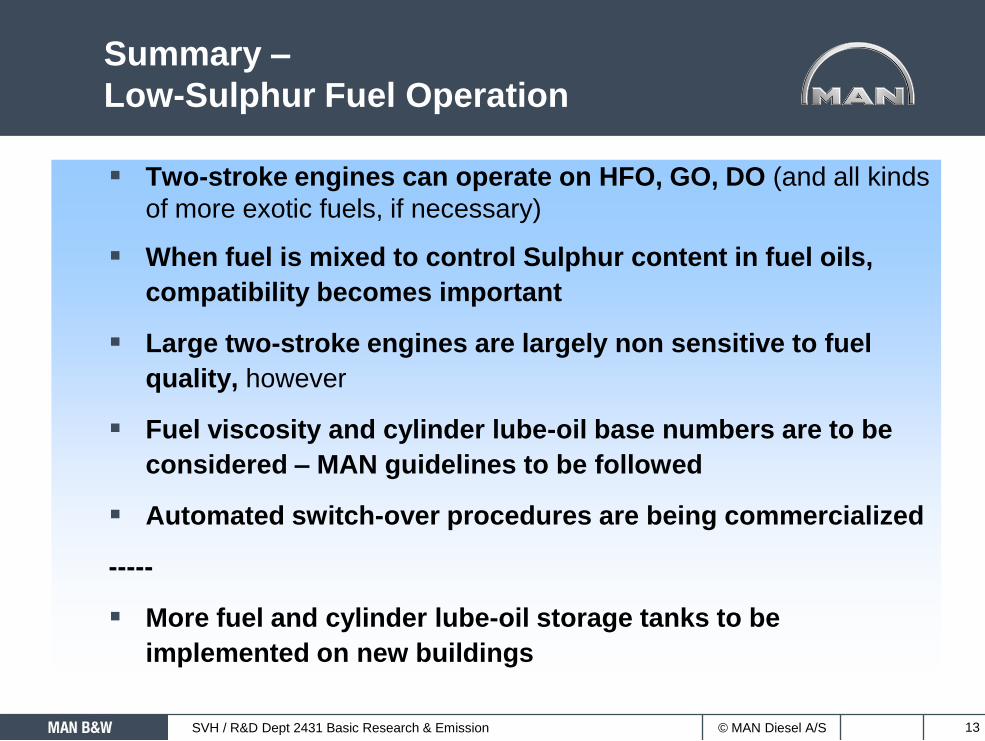
Summary –
Low-Sulphur Fuel Operation
Two-stroke engines can operate on HFO, GO, DO (and all kinds
of more exotic fuels, if necessary)
When fuel is mixed to control Sulphur content in fuel oils,
compatibility becomes important
Large two-stroke engines are largely non sensitive to fuel
quality, however
Fuel viscosity and cylinder lube-oil base numbers are to be
considered – MAN guidelines to be followed
Automated switch-over procedures are being commercialized
-----
More fuel and cylinder lube-oil storage tanks to be
implemented on new buildings

© MAN Diesel A/SSVH / R&D Dept 2431 Basic Research & Emission 14
DISCUSSION
Svend Henningsen
MD-C, R&D, Process Development, Emission

© MAN Diesel A/SSVH / R&D Dept 2431 Basic Research & Emission 15
Influence of Fuel Spec Parameters
Density – Centrifuges
Viscosity – Reheating
Flash point – Safety
Pour point – Handling
Carbon Residue – Fouling of gas ways
Ash – Can be abrasive
Vanadium and sodium – Corrosion and T/C deposits
Sullfur – Corrosion
Water – Centrifuges
Catalytic fines – Centrifuges
Off-spec. Fuels – Natural gas, Bitumen, Orimulsion
Bio fuel
[Database ref. and Dept/Ref.…] 2006/09/01

© MAN Diesel A/SSVH / R&D Dept 2431 Basic Research & Emission 16
Injection timing
on the 4T50MX test engine
Test series: Propeller curve: 10, 25, 50, 75, 100 % load
Generator curve: 10, 25, 50, 75, 100 % load

© MAN Diesel A/SSVH / R&D Dept 2431 Basic Research & Emission 17
Comparison of Lube BN Performance
(New Licencee Letter)
[Database ref. and Dept/Ref.…]
0.00
0.20
0.40
0.60
0.80
1.00
1.20
1.40
0 0.5 1 1.5 2 2.5 3 3.5 4 4.5 5
Ab
so
lute
do
sa
ge
s (
g/k
Wh
)
Sulphur %
BN50: 0.36g/kWh x S%
BN70: 0.26g/kWh x S%
SE
CA Degree of overadditivation using BN70
Theoretical extra lubrication using BN40
Degree of overadditivation using BN60
BN60: 0.30g/kWh x S%
BN40: 0.45g/kWh x S%
Extra amount of BN60 oil to be used compared to BN70
© MAN Diesel A/SSVH / R&D Dept 2431 Basic Research & Emission 18
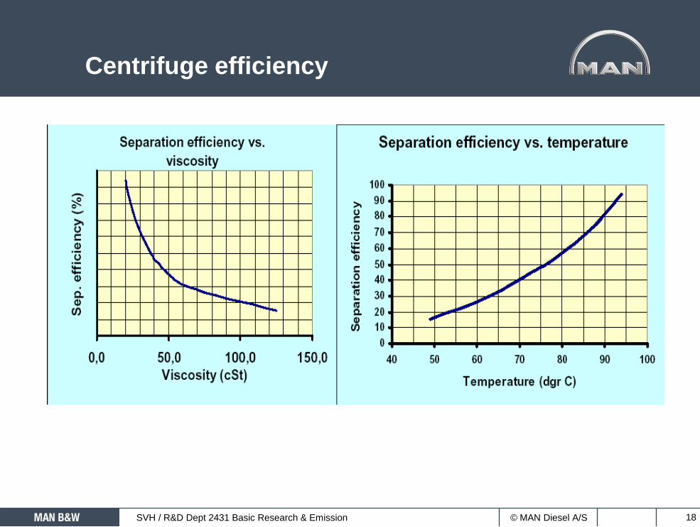
Centrifuge efficiency

© MAN Diesel A/SSVH / R&D Dept 2431 Basic Research & Emission 19
External factors which influences
engine condition
Cylinder lube oil
Quality
Type (BN)
Dosage
Fuel oil
Viscosity
Contaminants
Cat fines (treatment, purification)
Ambient condition
Humidity
Water mist catcher
Exhaust gas boiler
Pressure drop in exhaust system

© MAN Diesel A/SSVH / R&D Dept 2431 Basic Research & Emission 20
Cylinder-Liner Surface
L/71509-0.0/0301 (2160/KEA)

© MAN Diesel A/SSVH / R&D Dept 2431 Basic Research & Emission 21
Damage to Fuel-Pump Plunger
L/3330187/20030423 (2160/KEA)

© MAN Diesel A/SSVH / R&D Dept 2431 Basic Research & Emission 22
One MDO Settling Tank and Two Sets HFO
Settling Tank and Service Tanks
3332008.2004.11.05 (2160/KEA)
Service
Tank
(day)
35°C
Service
Tank
(day)
90°C
Centrifuge(s)
(40°C)
Centrifuge(s)
(95 - 100 °C)
Service
Tank
(day)
90°CCentrifuge(s)
(95 - 100 °C)
HFO
Supply
pump
HFO
Circulating
pump
If unifuel system
To GensetsMDO Storage Tank (25°C)
Sett
ling
Tank
( 25
°C)
Se
ttlin
gan
k1
( 60
°C)
Bunker Storage Tank 1 (45°C)
Bunker Storage Tank 2 (45°C)
Bunker Storage Tank 3 (45°C)
Sett
ling
ank
2( 6
0°C
)T
T
© MAN Diesel A/SSVH / R&D Dept 2431 Basic Research & Emission 23
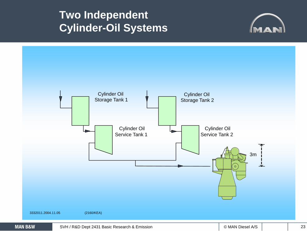
Two Independent
Cylinder-Oil Systems
Cylinder OilStorage Tank 1
Cylinder Oil
Service Tank 1
Cylinder OilStorage Tank 2
Cylinder Oil
Service Tank 2
3m
3332011.2004.11.05 (2160/KEA)

© MAN Diesel A/SSVH / R&D Dept 2431 Basic Research & Emission 24
3332014.2004.11.05 (2100/KEA)
Fuel-Oil System

© MAN Diesel A/SSVH / R&D Dept 2431 Basic Research & Emission 25
MBD test of different fuels