1066483A04 Prodigy Color-on-Demand Controller and Control ...
41
Prodigyr Color-on-Demandr Controller and Control Panel Customer Product Manual Part 1066483A04 Issued 03/09 NORDSON CORPORATION AMHERST, OHIO USA For parts and technical support, call the Finishing Customer Support Center at (800) 433-9319. This document is available on the Internet at http://emanuals.nordson.com/finishing
Transcript of 1066483A04 Prodigy Color-on-Demand Controller and Control ...
Prodigy� Color-on-Demand�Controller and Control Panel
Customer Product ManualPart 1066483A04
Issued 03/09
NORDSON CORPORATION AMHERST, OHIO USA
For parts and technical support, call the Finishing Customer Support Center at (800) 433-9319.
This document is available on the Internet at http://emanuals.nordson.com/finishing
Nick.Klasovsky
Rectangle
Part 1066483A04 � 2009 Nordson Corporation
Table of ContentsSafety 1. . . . . . . . . . . . . . . . . . . . . . . . . . . . . . . . . . . . . . .
Qualified Personnel 1. . . . . . . . . . . . . . . . . . . . . . . . .Intended Use 1. . . . . . . . . . . . . . . . . . . . . . . . . . . . . .Regulations and Approvals 1. . . . . . . . . . . . . . . . . .Personal Safety 1. . . . . . . . . . . . . . . . . . . . . . . . . . . .Fire Safety 2. . . . . . . . . . . . . . . . . . . . . . . . . . . . . . . .Grounding 2. . . . . . . . . . . . . . . . . . . . . . . . . . . . . . . . .Action in the Event of a Malfunction 2. . . . . . . . . . .Disposal 2. . . . . . . . . . . . . . . . . . . . . . . . . . . . . . . . . .
Description 3. . . . . . . . . . . . . . . . . . . . . . . . . . . . . . . . . .System Operation 4. . . . . . . . . . . . . . . . . . . . . . . . . .
Accumulator Tank Function 4. . . . . . . . . . . . . . .Color Change Manifold 4. . . . . . . . . . . . . . . . . . .
Color-on-Demand Controller Setup and Operation 6.Screen Map 6. . . . . . . . . . . . . . . . . . . . . . . . . . . . . . .Color Change without Suction Line Purge 7. . . . .Button Labeling 8. . . . . . . . . . . . . . . . . . . . . . . . . . . .System Cleaning 8. . . . . . . . . . . . . . . . . . . . . . . . . . .Color Change with Suction Line Purge 9. . . . . . . .Valve Counters 9. . . . . . . . . . . . . . . . . . . . . . . . . . . .System Clock 10. . . . . . . . . . . . . . . . . . . . . . . . . . . . . .Software Version 10. . . . . . . . . . . . . . . . . . . . . . . . . . .
Screen Brightness 10. . . . . . . . . . . . . . . . . . . . . . .Troubleshooting 10. . . . . . . . . . . . . . . . . . . . . . . . . . . . .
Inputs 11. . . . . . . . . . . . . . . . . . . . . . . . . . . . . . . . . . . .Outputs 12. . . . . . . . . . . . . . . . . . . . . . . . . . . . . . . . . . .Powder Flow 12. . . . . . . . . . . . . . . . . . . . . . . . . . . . . .Service Screen 13. . . . . . . . . . . . . . . . . . . . . . . . . . . . 13. . . . . . . . . . . . . . . . . . . . . . . . . . . . . . . . . . . . . . . . . .
Repair 13. . . . . . . . . . . . . . . . . . . . . . . . . . . . . . . . . . . . . .Parts 14. . . . . . . . . . . . . . . . . . . . . . . . . . . . . . . . . . . . . . .
Controller Kit Parts 14. . . . . . . . . . . . . . . . . . . . . . . . .Controller Parts 16. . . . . . . . . . . . . . . . . . . . . . . . . . . .
Retrofit Kit 16. . . . . . . . . . . . . . . . . . . . . . . . . . . . . .Color Change Control Panel Parts 18. . . . . . . . . . . .Control Unit (PLC) Parts 20. . . . . . . . . . . . . . . . . . . .Ship-With Kit Parts 22. . . . . . . . . . . . . . . . . . . . . . . . .
Diagrams and Schematics 23. . . . . . . . . . . . . . . . . . . .Controller Wiring Diagram 23. . . . . . . . . . . . . . . . . . . .Control Panel Internal Pneumatic Diagram 24. . . . .Control Panel External Pneumatic Diagram 25. . . .Control Panel Wiring Diagram (Sheet 1 of 2) 26. . .Control Panel Wiring Diagram (Sheet 2 of 2) 27. . .Control Panel Schematic (Sheet 1 of 10) 28. . . . . .Control Panel Schematic (Sheet 2 of 10) 29. . . . . .Control Panel Schematic (Sheet 3 of 10) 30. . . . . .Control Panel Schematic (Sheet 4 of 10) 31. . . . . .Control Panel Schematic (Sheet 5 of 10) 32. . . . . .Control Panel Schematic (Sheet 6 of 10) 33. . . . . .Control Panel Schematic (Sheet 7 of 10) 34. . . . . .Control Panel Schematic (Sheet 8 of 10) 35. . . . . .Control Panel Schematic (Sheet 9 of 10) 36. . . . . .Control Panel Schematic (Sheet 10 of 10) 37. . . . .
Contact UsNordson Corporation welcomes requests for information, comments, andinquiries about its products. General information about Nordson can befound on the Internet using the following address:http://www.nordson.com.Address all correspondence to:
Nordson CorporationAttn: Customer Service555 Jackson StreetAmherst, OH 44001
NoticeThis is a Nordson Corporation publication which is protected by copyright.Original copyright date 2005. No part of this document may bephotocopied, reproduced, or translated to another language without theprior written consent of Nordson Corporation. The information containedin this publication is subject to change without notice.
Trademarks
Nordson and the Nordson logo are registered trademarks of NordsonCorporation.
Prodigy and Color-on-Demand are trademarks of Nordson Corporation.
DECLARATION of CONFORMITY
PRODUCT:
Prodigy Color on Demand, HDLV Manual Pump Cabinet and ControlsOne or two gun, manual pump system for use with a Manual Applicator and Controller.
APPLICABLE DIRECTIVES:
98/37/EEC (Machinery)2006/95/EC (Low–Voltage Directive)2004/108/EEC (Elecromagnetic Compatibility Directive)
STANDARDS USED TO VERIFY COMPLIANCE:
IEC60417 EN61000–6–2EN12100 EN55011EN60204 EN61000–6–3NFPA79
PRINCIPLES:
This product has been manufactured according to good engineering practice.The product specified conforms to the directive and standards described above.
Quality Certificate:
DNV ISO9001:2000
Date: 15 October 2007
Joseph SchroederEngineering Manager, Finishing Product Development Group
Nordson Corporation � Westlake, Ohio DOC14019A02

Color-on-Demand� Controller and Control Panel 1
Part 1066483A04� 2009 Nordson Corporation
Color-on-Demand� Controller and Control Panel
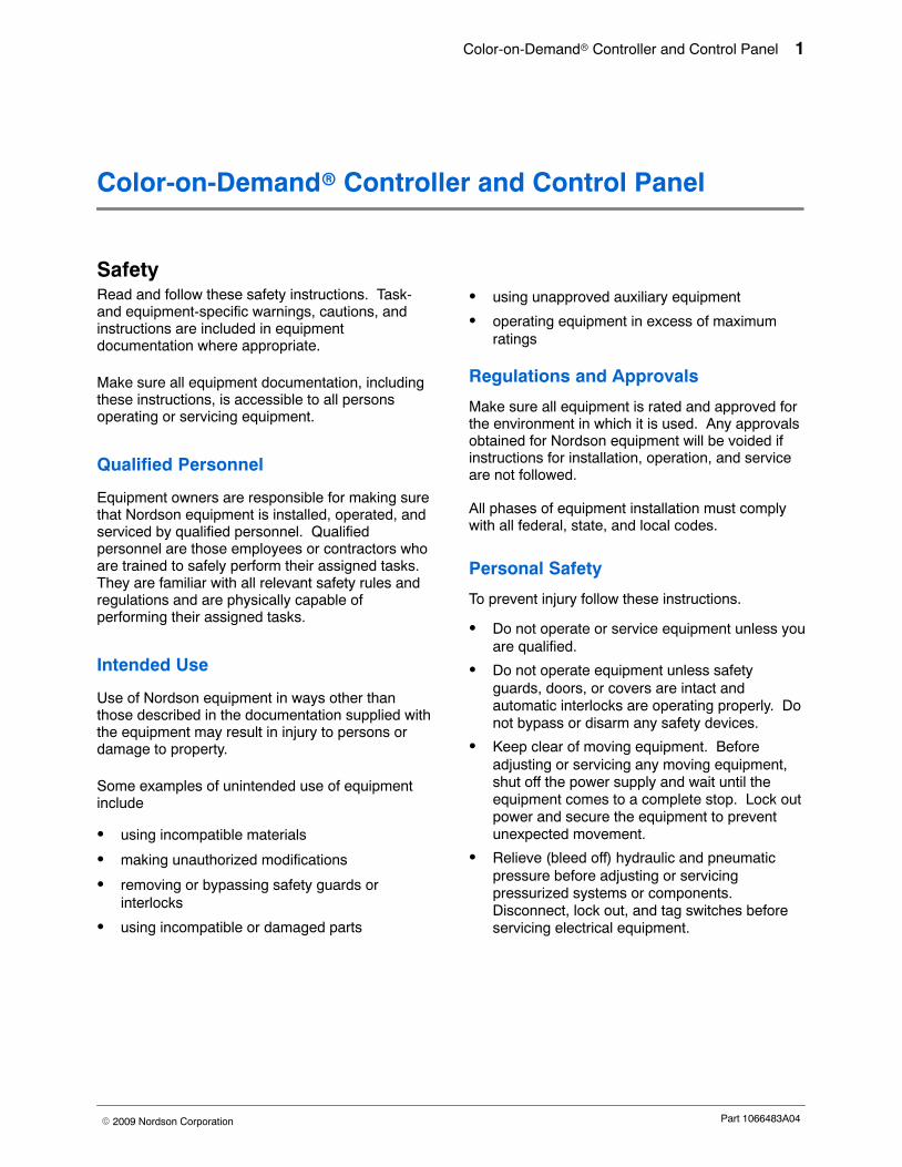
Safety Read and follow these safety instructions. Task-and equipment-specific warnings, cautions, andinstructions are included in equipmentdocumentation where appropriate.
Make sure all equipment documentation, includingthese instructions, is accessible to all personsoperating or servicing equipment.
Qualified Personnel
Equipment owners are responsible for making surethat Nordson equipment is installed, operated, andserviced by qualified personnel. Qualifiedpersonnel are those employees or contractors whoare trained to safely perform their assigned tasks.They are familiar with all relevant safety rules andregulations and are physically capable ofperforming their assigned tasks.
Intended Use
Use of Nordson equipment in ways other thanthose described in the documentation supplied withthe equipment may result in injury to persons ordamage to property.
Some examples of unintended use of equipmentinclude
� using incompatible materials
� making unauthorized modifications
� removing or bypassing safety guards orinterlocks
� using incompatible or damaged parts
� using unapproved auxiliary equipment
� operating equipment in excess of maximumratings
Regulations and Approvals
Make sure all equipment is rated and approved forthe environment in which it is used. Any approvalsobtained for Nordson equipment will be voided ifinstructions for installation, operation, and serviceare not followed.
All phases of equipment installation must complywith all federal, state, and local codes.
Personal Safety
To prevent injury follow these instructions.
� Do not operate or service equipment unless youare qualified.
� Do not operate equipment unless safetyguards, doors, or covers are intact andautomatic interlocks are operating properly. Donot bypass or disarm any safety devices.
� Keep clear of moving equipment. Beforeadjusting or servicing any moving equipment,shut off the power supply and wait until theequipment comes to a complete stop. Lock outpower and secure the equipment to preventunexpected movement.
� Relieve (bleed off) hydraulic and pneumaticpressure before adjusting or servicingpressurized systems or components.Disconnect, lock out, and tag switches beforeservicing electrical equipment.
Color-on-Demand� Controller and Control Panel2
Part 1066483A04 � 2009 Nordson Corporation
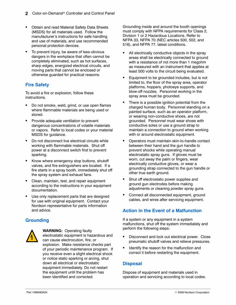
� Obtain and read Material Safety Data Sheets(MSDS) for all materials used. Follow themanufacturer’s instructions for safe handlingand use of materials, and use recommendedpersonal protection devices.
� To prevent injury, be aware of less-obviousdangers in the workplace that often cannot becompletely eliminated, such as hot surfaces,sharp edges, energized electrical circuits, andmoving parts that cannot be enclosed orotherwise guarded for practical reasons.
Fire Safety
To avoid a fire or explosion, follow theseinstructions.
� Do not smoke, weld, grind, or use open flameswhere flammable materials are being used orstored.
� Provide adequate ventilation to preventdangerous concentrations of volatile materialsor vapors. Refer to local codes or your materialMSDS for guidance.
� Do not disconnect live electrical circuits whileworking with flammable materials. Shut offpower at a disconnect switch first to preventsparking.
� Know where emergency stop buttons, shutoffvalves, and fire extinguishers are located. If afire starts in a spray booth, immediately shut offthe spray system and exhaust fans.
� Clean, maintain, test, and repair equipmentaccording to the instructions in your equipmentdocumentation.
� Use only replacement parts that are designedfor use with original equipment. Contact yourNordson representative for parts informationand advice.
Grounding
WARNING: Operating faultyelectrostatic equipment is hazardous andcan cause electrocution, fire, orexplosion. Make resistance checks partof your periodic maintenance program. Ifyou receive even a slight electrical shockor notice static sparking or arcing, shutdown all electrical or electrostaticequipment immediately. Do not restartthe equipment until the problem hasbeen identified and corrected.
Grounding inside and around the booth openingsmust comply with NFPA requirements for Class 2,Division 1 or 2 Hazardous Locations. Refer toNFPA 33, NFPA 70 (NEC articles 500, 502, and516), and NFPA 77, latest conditions.
� All electrically conductive objects in the sprayareas shall be electrically connected to groundwith a resistance of not more than 1 megohmas measured with an instrument that applies atleast 500 volts to the circuit being evaluated.
� Equipment to be grounded includes, but is notlimited to, the floor of the spray area, operatorplatforms, hoppers, photoeye supports, andblow-off nozzles. Personnel working in thespray area must be grounded.
� There is a possible ignition potential from thecharged human body. Personnel standing on apainted surface, such as an operator platform,or wearing non-conductive shoes, are notgrounded. Personnel must wear shoes withconductive soles or use a ground strap tomaintain a connection to ground when workingwith or around electrostatic equipment.
� Operators must maintain skin-to-handle contactbetween their hand and the gun handle toprevent shocks while operating manualelectrostatic spray guns. If gloves must beworn, cut away the palm or fingers, wearelectrically conductive gloves, or wear agrounding strap connected to the gun handle orother true earth ground.
� Shut off electrostatic power supplies andground gun electrodes before makingadjustments or cleaning powder spray guns.
� Connect all disconnected equipment, groundcables, and wires after servicing equipment.
Action in the Event of a Malfunction
If a system or any equipment in a systemmalfunctions, shut off the system immediately andperform the following steps:
� Disconnect and lock out electrical power. Closepneumatic shutoff valves and relieve pressures.
� Identify the reason for the malfunction andcorrect it before restarting the equipment.
Disposal
Dispose of equipment and materials used inoperation and servicing according to local codes.
Color-on-Demand� Controller and Control Panel 3
Part 1066483A04� 2009 Nordson Corporation
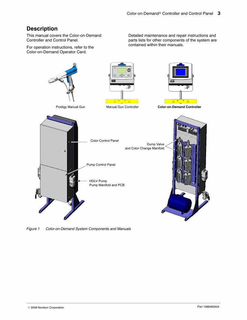
Description This manual covers the Color-on-DemandController and Control Panel.
For operation instructions, refer to theColor-on-Demand Operator Card.
Detailed maintenance and repair instructions andparts lists for other components of the system arecontained within their manuals.
Color-on-Demand Controller
Color-Control Panel
HDLV PumpPump Manifold and PCB
Pump Control Panel
Dump Valveand Color Change Manifold
Manual Gun ControllerProdigy Manual Gun
Figure 1 Color-on-Demand System Components and Manuals
Color-on-Demand� Controller and Control Panel4
Part 1066483A04 � 2009 Nordson Corporation
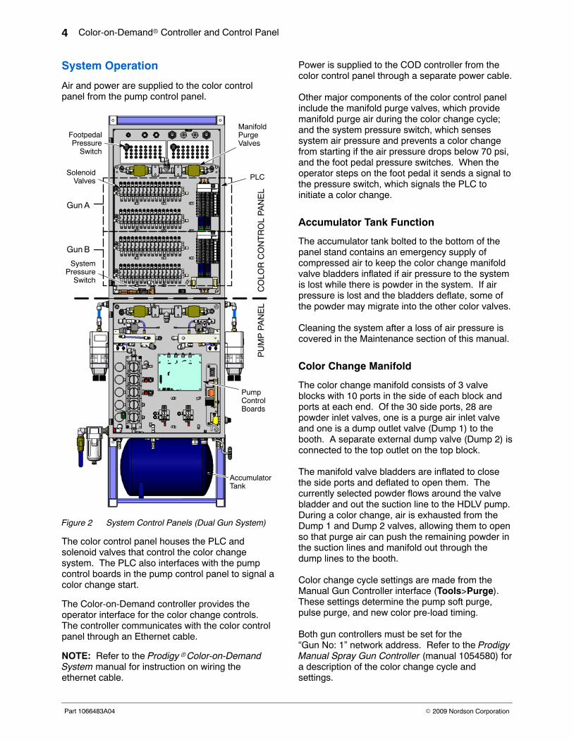
System Operation
Air and power are supplied to the color controlpanel from the pump control panel.
AGun
Gun B
ManifoldPurgeValves
PLC
FootpedalPressure
Switch
SolenoidValves
SystemPressure
Switch
PumpControlBoards
AccumulatorTank
CO
LOR
CO
NT
RO
L P
AN
EL
PU
MP
PA
NE
L
Figure 2 System Control Panels (Dual Gun System)
The color control panel houses the PLC andsolenoid valves that control the color changesystem. The PLC also interfaces with the pumpcontrol boards in the pump control panel to signal acolor change start.
The Color-on-Demand controller provides theoperator interface for the color change controls.The controller communicates with the color controlpanel through an Ethernet cable.
NOTE: Refer to the Prodigy� Color-on-DemandSystem manual for instruction on wiring theethernet cable.
Power is supplied to the COD controller from thecolor control panel through a separate power cable.
Other major components of the color control panelinclude the manifold purge valves, which providemanifold purge air during the color change cycle;and the system pressure switch, which sensessystem air pressure and prevents a color changefrom starting if the air pressure drops below 70 psi,and the foot pedal pressure switches. When theoperator steps on the foot pedal it sends a signal tothe pressure switch, which signals the PLC toinitiate a color change.
Accumulator Tank Function
The accumulator tank bolted to the bottom of thepanel stand contains an emergency supply ofcompressed air to keep the color change manifoldvalve bladders inflated if air pressure to the systemis lost while there is powder in the system. If airpressure is lost and the bladders deflate, some ofthe powder may migrate into the other color valves.
Cleaning the system after a loss of air pressure iscovered in the Maintenance section of this manual.
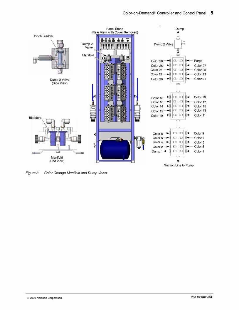
Color Change Manifold
The color change manifold consists of 3 valveblocks with 10 ports in the side of each block andports at each end. Of the 30 side ports, 28 arepowder inlet valves, one is a purge air inlet valveand one is a dump outlet valve (Dump 1) to thebooth. A separate external dump valve (Dump 2) isconnected to the top outlet on the top block.
The manifold valve bladders are inflated to closethe side ports and deflated to open them. Thecurrently selected powder flows around the valvebladder and out the suction line to the HDLV pump.During a color change, air is exhausted from theDump 1 and Dump 2 valves, allowing them to openso that purge air can push the remaining powder inthe suction lines and manifold out through thedump lines to the booth.
Color change cycle settings are made from theManual Gun Controller interface (Tools>Purge).These settings determine the pump soft purge,pulse purge, and new color pre-load timing.
Both gun controllers must be set for the“Gun No: 1” network address. Refer to the ProdigyManual Spray Gun Controller (manual 1054580) fora description of the color change cycle andsettings.
Color-on-Demand� Controller and Control Panel 5
Part 1066483A04� 2009 Nordson Corporation
P1A
Color 28Color 26Color 24
Color 22
Color 20
Purge
Color 27Color 25
Color 23Color 21
Color 19
Color 17Color 15Color 13
Color 11
Color 9Color 7Color 5Color 3
Color 1
Color 18Color 16Color 14
Color 12Color 10
Color 8Color 6Color 4
Color 2Dump 1
Suction Line to Pump
Dump
Dump 2Valve
Manifold A B
Manifold(End View)
Panel Stand(Rear View, with Cover Removed)
Dump 2 Valve(Side View)
Pinch Bladder
Bladders
Dump 2 Valve
Figure 3 Color Change Manifold and Dump Valve
Color-on-Demand� Controller and Control Panel6
Part 1066483A04 � 2009 Nordson Corporation
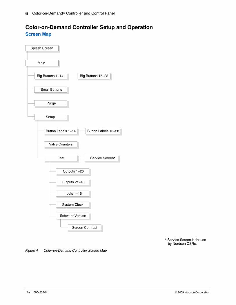
Color-on-Demand Controller Setup and Operation Screen Map
Big Buttons 15−28Big Buttons 1−14
Main
Splash Screen
Small Buttons
Setup
Button Labels 1−14
Valve Counters
Test
Outputs 1−20
Outputs 21−40
Inputs 1−16
Software Version
Screen Contrast
Button Labels 15−28
System Clock
Purge
Service Screen*
* Service Screen is for use by Nordson CSRs.
Figure 4 Color-on-Demand Controller Screen Map
Color-on-Demand� Controller and Control Panel 7
Part 1066483A04� 2009 Nordson Corporation
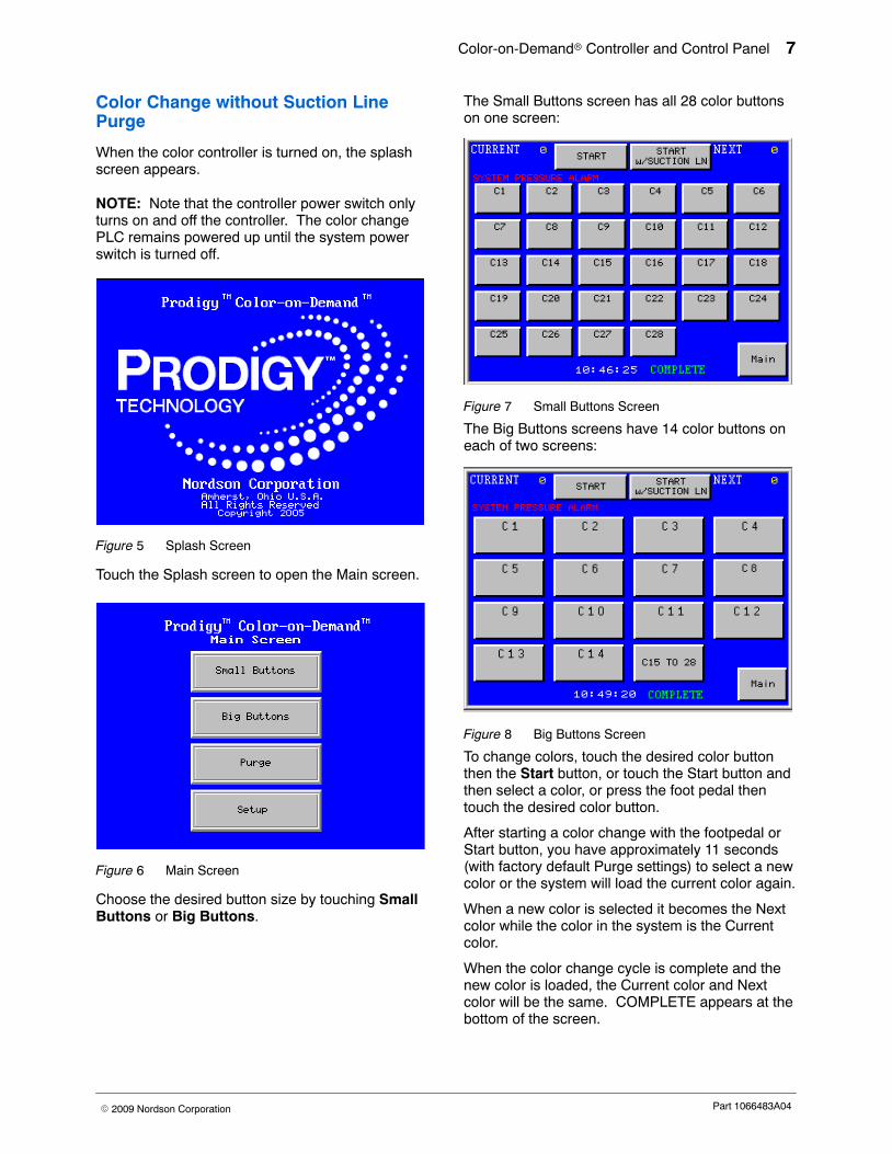
Color Change without Suction LinePurge
When the color controller is turned on, the splashscreen appears.
NOTE: Note that the controller power switch onlyturns on and off the controller. The color changePLC remains powered up until the system powerswitch is turned off.
Figure 5 Splash Screen
Touch the Splash screen to open the Main screen.
Figure 6 Main Screen
Choose the desired button size by touching SmallButtons or Big Buttons.
The Small Buttons screen has all 28 color buttonson one screen:
Figure 7 Small Buttons Screen
The Big Buttons screens have 14 color buttons oneach of two screens:
Figure 8 Big Buttons Screen
To change colors, touch the desired color buttonthen the Start button, or touch the Start button andthen select a color, or press the foot pedal thentouch the desired color button.
After starting a color change with the footpedal orStart button, you have approximately 11 seconds(with factory default Purge settings) to select a newcolor or the system will load the current color again.
When a new color is selected it becomes the Nextcolor while the color in the system is the Currentcolor.
When the color change cycle is complete and thenew color is loaded, the Current color and Nextcolor will be the same. COMPLETE appears at thebottom of the screen.
Color-on-Demand� Controller and Control Panel8
Part 1066483A04 � 2009 Nordson Corporation
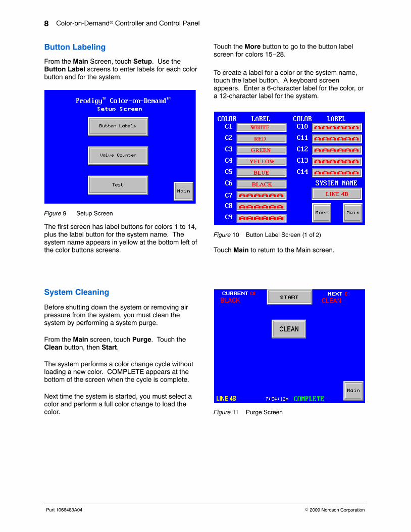
Button Labeling
From the Main Screen, touch Setup. Use theButton Label screens to enter labels for each colorbutton and for the system.
Figure 9 Setup Screen
The first screen has label buttons for colors 1 to 14,plus the label button for the system name. Thesystem name appears in yellow at the bottom left ofthe color buttons screens.
Touch the More button to go to the button labelscreen for colors 15−28.
To create a label for a color or the system name,touch the label button. A keyboard screenappears. Enter a 6-character label for the color, ora 12-character label for the system.
Figure 10 Button Label Screen (1 of 2)
Touch Main to return to the Main screen.
System Cleaning
Before shutting down the system or removing airpressure from the system, you must clean thesystem by performing a system purge.
From the Main screen, touch Purge. Touch theClean button, then Start.
The system performs a color change cycle withoutloading a new color. COMPLETE appears at thebottom of the screen when the cycle is complete.
Next time the system is started, you must select acolor and perform a full color change to load thecolor. Figure 11 Purge Screen
Color-on-Demand� Controller and Control Panel 9
Part 1066483A04� 2009 Nordson Corporation
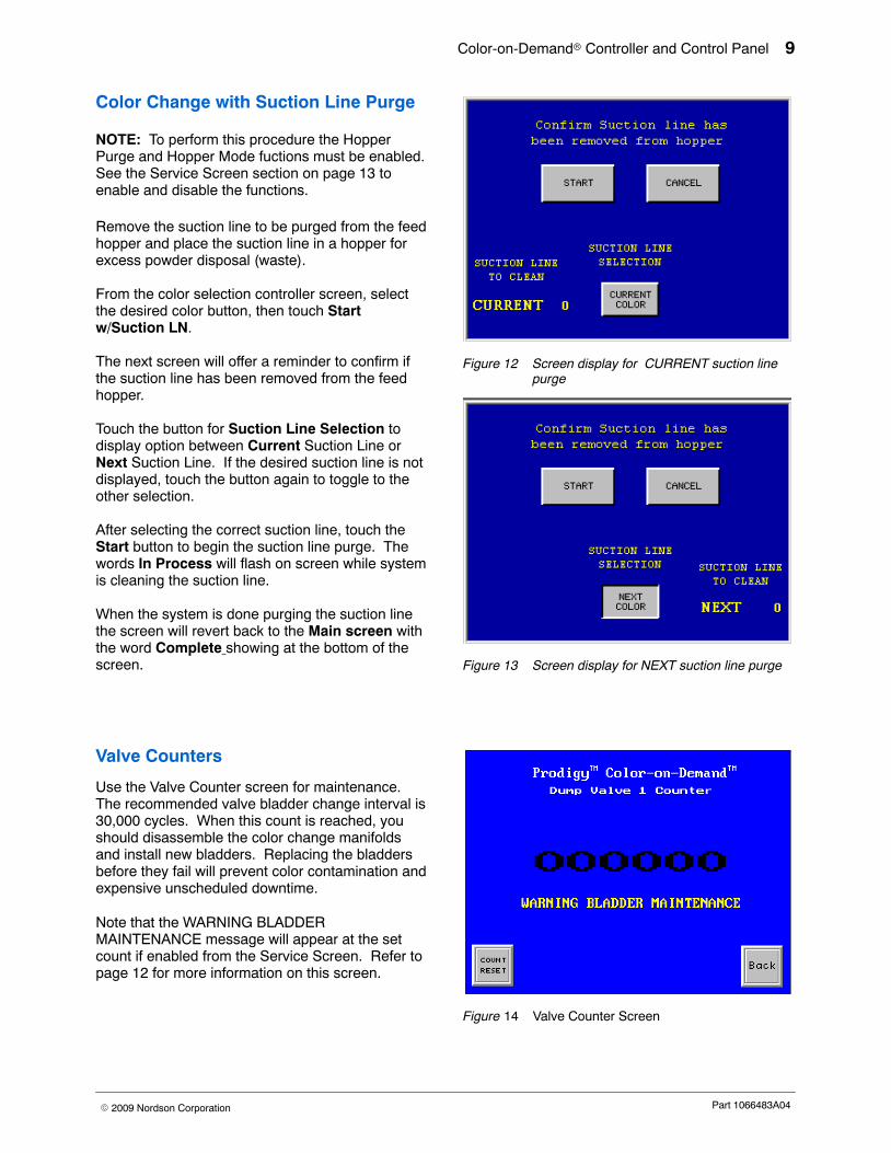
Color Change with Suction Line Purge
NOTE: To perform this procedure the HopperPurge and Hopper Mode fuctions must be enabled.See the Service Screen section on page 13 toenable and disable the functions.
Remove the suction line to be purged from the feedhopper and place the suction line in a hopper forexcess powder disposal (waste).
From the color selection controller screen, selectthe desired color button, then touch Startw/Suction LN.
The next screen will offer a reminder to confirm ifthe suction line has been removed from the feedhopper.
Touch the button for Suction Line Selection todisplay option between Current Suction Line orNext Suction Line. If the desired suction line is notdisplayed, touch the button again to toggle to theother selection.
After selecting the correct suction line, touch theStart button to begin the suction line purge. Thewords In Process will flash on screen while systemis cleaning the suction line.
When the system is done purging the suction linethe screen will revert back to the Main screen withthe word Complete showing at the bottom of thescreen.
Figure 12 Screen display for CURRENT suction linepurge
Figure 13 Screen display for NEXT suction line purge
Valve Counters
Use the Valve Counter screen for maintenance.The recommended valve bladder change interval is30,000 cycles. When this count is reached, youshould disassemble the color change manifoldsand install new bladders. Replacing the bladdersbefore they fail will prevent color contamination andexpensive unscheduled downtime.
Note that the WARNING BLADDERMAINTENANCE message will appear at the setcount if enabled from the Service Screen. Refer topage 12 for more information on this screen.
Figure 14 Valve Counter Screen
Color-on-Demand� Controller and Control Panel10
Part 1066483A04 � 2009 Nordson Corporation
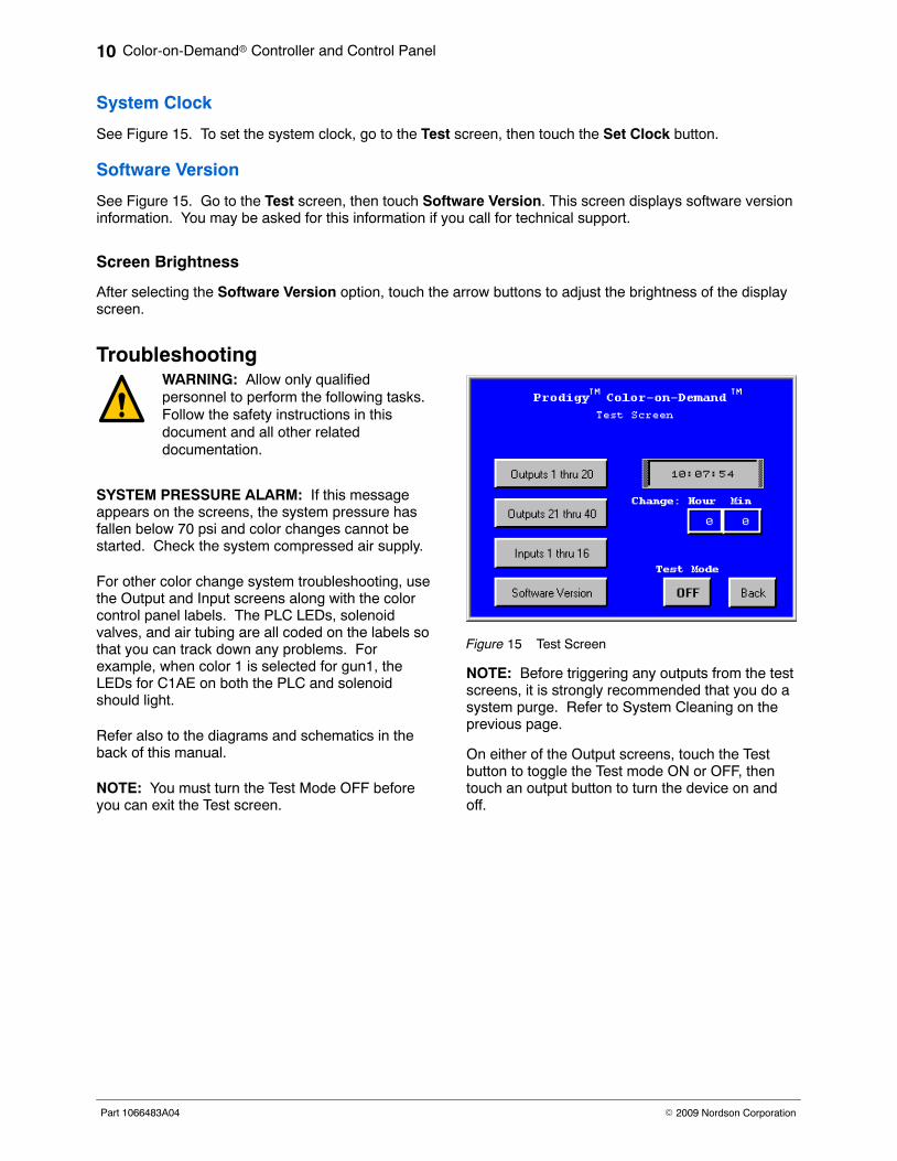
System Clock
See Figure 15. To set the system clock, go to the Test screen, then touch the Set Clock button.
Software Version
See Figure 15. Go to the Test screen, then touch Software Version. This screen displays software versioninformation. You may be asked for this information if you call for technical support.
Screen Brightness
After selecting the Software Version option, touch the arrow buttons to adjust the brightness of the displayscreen.
Troubleshooting WARNING: Allow only qualifiedpersonnel to perform the following tasks.Follow the safety instructions in thisdocument and all other relateddocumentation.
SYSTEM PRESSURE ALARM: If this messageappears on the screens, the system pressure hasfallen below 70 psi and color changes cannot bestarted. Check the system compressed air supply.
For other color change system troubleshooting, usethe Output and Input screens along with the colorcontrol panel labels. The PLC LEDs, solenoidvalves, and air tubing are all coded on the labels sothat you can track down any problems. Forexample, when color 1 is selected for gun1, theLEDs for C1AE on both the PLC and solenoidshould light.
Refer also to the diagrams and schematics in theback of this manual.
NOTE: You must turn the Test Mode OFF beforeyou can exit the Test screen.
Figure 15 Test Screen
NOTE: Before triggering any outputs from the testscreens, it is strongly recommended that you do asystem purge. Refer to System Cleaning on theprevious page.
On either of the Output screens, touch the Testbutton to toggle the Test mode ON or OFF, thentouch an output button to turn the device on andoff.
Color-on-Demand� Controller and Control Panel 11
Part 1066483A04� 2009 Nordson Corporation
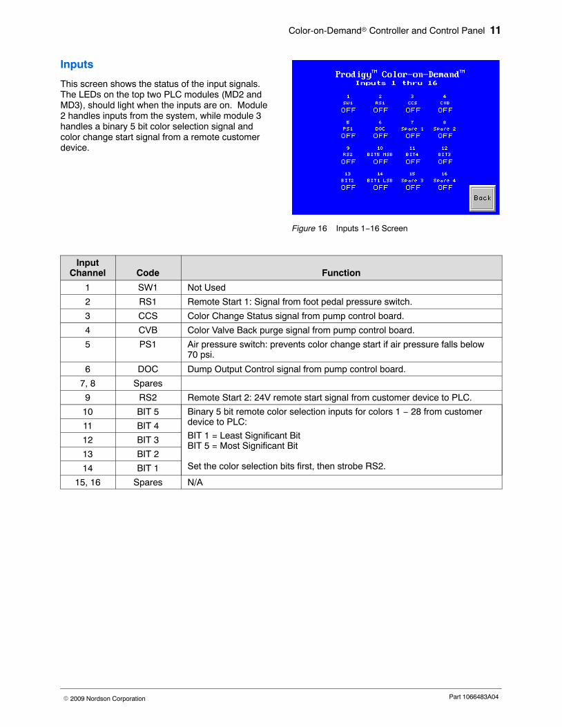
Inputs
This screen shows the status of the input signals.The LEDs on the top two PLC modules (MD2 andMD3), should light when the inputs are on. Module2 handles inputs from the system, while module 3handles a binary 5 bit color selection signal andcolor change start signal from a remote customerdevice.
Figure 16 Inputs 1−16 Screen
InputChannel Code Function
1 SW1 Not Used
2 RS1 Remote Start 1: Signal from foot pedal pressure switch.
3 CCS Color Change Status signal from pump control board.
4 CVB Color Valve Back purge signal from pump control board.
5 PS1 Air pressure switch: prevents color change start if air pressure falls below70 psi.
6 DOC Dump Output Control signal from pump control board.
7, 8 Spares
9 RS2 Remote Start 2: 24V remote start signal from customer device to PLC.
10 BIT 5 Binary 5 bit remote color selection inputs for colors 1 − 28 from customerdevice to PLC:
BIT 1 = Least Significant BitBIT 5 = Most Significant Bit
Set the color selection bits first, then strobe RS2.
11 BIT 4
12 BIT 3
13 BIT 2
14 BIT 1
15, 16 Spares N/A
Color-on-Demand� Controller and Control Panel12
Part 1066483A04 � 2009 Nordson Corporation
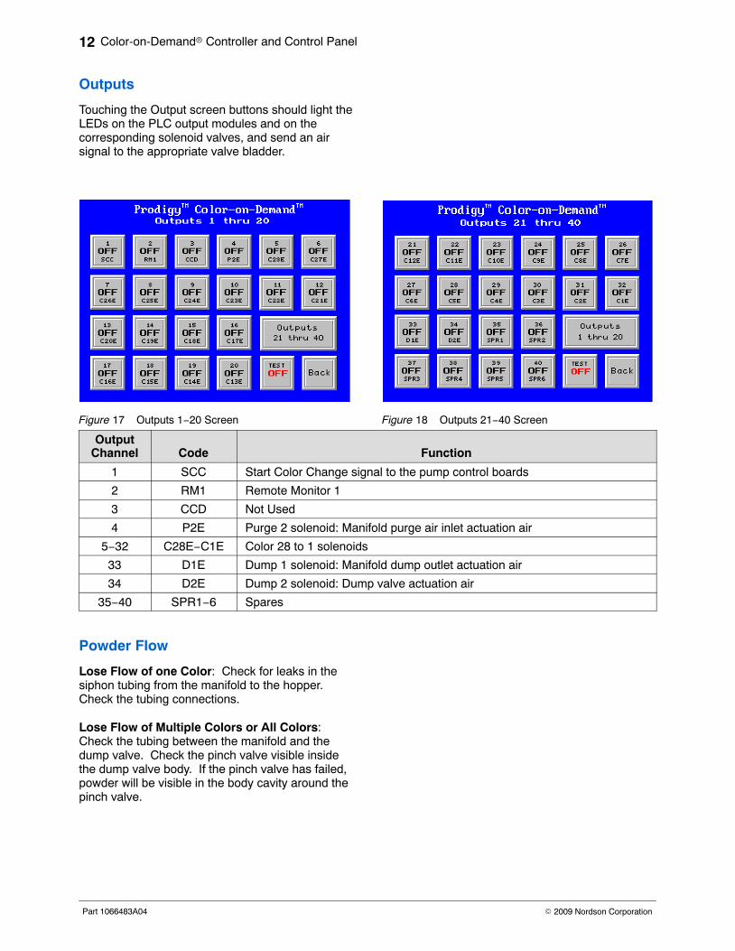
Outputs
Touching the Output screen buttons should light theLEDs on the PLC output modules and on thecorresponding solenoid valves, and send an airsignal to the appropriate valve bladder.
Figure 17 Outputs 1−20 Screen Figure 18 Outputs 21−40 Screen
OutputChannel Code Function
1 SCC Start Color Change signal to the pump control boards
2 RM1 Remote Monitor 1
3 CCD Not Used
4 P2E Purge 2 solenoid: Manifold purge air inlet actuation air
5−32 C28E−C1E Color 28 to 1 solenoids
33 D1E Dump 1 solenoid: Manifold dump outlet actuation air
34 D2E Dump 2 solenoid: Dump valve actuation air
35−40 SPR1−6 Spares
Powder Flow
Lose Flow of one Color: Check for leaks in thesiphon tubing from the manifold to the hopper.Check the tubing connections.
Lose Flow of Multiple Colors or All Colors:Check the tubing between the manifold and thedump valve. Check the pinch valve visible insidethe dump valve body. If the pinch valve has failed,powder will be visible in the body cavity around thepinch valve.
Color-on-Demand� Controller and Control Panel 13
Part 1066483A04� 2009 Nordson Corporation
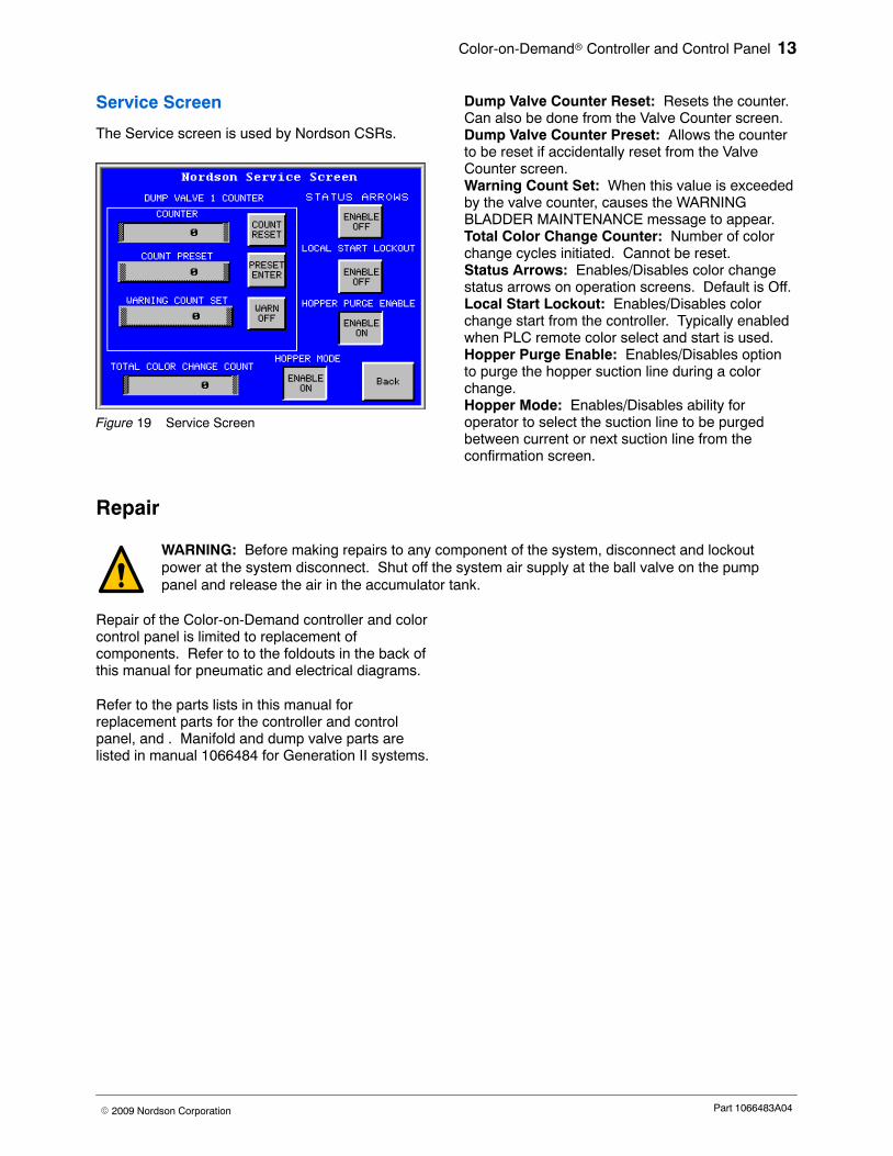
Service Screen
The Service screen is used by Nordson CSRs.
Figure 19 Service Screen
Dump Valve Counter Reset: Resets the counter.Can also be done from the Valve Counter screen.Dump Valve Counter Preset: Allows the counterto be reset if accidentally reset from the ValveCounter screen.Warning Count Set: When this value is exceededby the valve counter, causes the WARNINGBLADDER MAINTENANCE message to appear.Total Color Change Counter: Number of colorchange cycles initiated. Cannot be reset.Status Arrows: Enables/Disables color changestatus arrows on operation screens. Default is Off.Local Start Lockout: Enables/Disables colorchange start from the controller. Typically enabledwhen PLC remote color select and start is used.Hopper Purge Enable: Enables/Disables optionto purge the hopper suction line during a colorchange.Hopper Mode: Enables/Disables ability foroperator to select the suction line to be purgedbetween current or next suction line from theconfirmation screen.
Repair
WARNING: Before making repairs to any component of the system, disconnect and lockoutpower at the system disconnect. Shut off the system air supply at the ball valve on the pumppanel and release the air in the accumulator tank.
Repair of the Color-on-Demand controller and colorcontrol panel is limited to replacement ofcomponents. Refer to to the foldouts in the back ofthis manual for pneumatic and electrical diagrams.
Refer to the parts lists in this manual forreplacement parts for the controller and controlpanel, and . Manifold and dump valve parts arelisted in manual 1066484 for Generation II systems.
Color-on-Demand� Controller and Control Panel14
Part 1066483A04 � 2009 Nordson Corporation
Parts
To order parts, call the Nordson Finishing Customer Support Center at (800) 433-9319 or contact your localNordson representative.
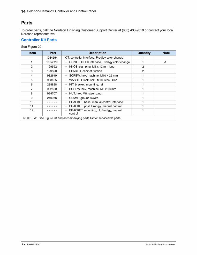
Controller Kit Parts
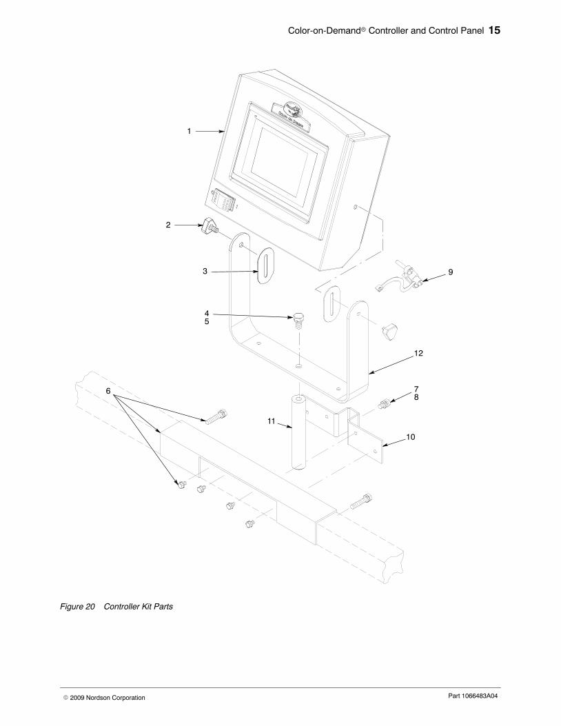
See Figure 20.
Item Part Description Quantity Note— 1084554 KIT, controller interface, Prodigy color change 1
1 1084529 � CONTROLLER interface, Prodigy color change 1 A
2 129592 � KNOB, clamping, M6 x 12 mm long 2
3 129590 � SPACER, cabinet, friction 2
4 982649 � SCREW, hex, machine, M10 x 22 mm 1
5 983405 � WASHER, lock, split, M10, steel, zinc 1
6 288828 � KIT, bracket, mounting, rail 1
7 982500 � SCREW, hex, machine, M8 x 16 mm 1
8 984707 � NUT, hex, M8, steel, zinc 1
9 240976 � CLAMP, ground w/wire 110 - - - - - - � BRACKET, base, manual control interface 111 - - - - - - � BRACKET, post, Prodigy, manual control 112 - - - - - - � BRACKET, mounting, U, Prodigy, manual
control1
NOTE A: See Figure 20 and accompanying parts list for serviceable parts.
Color-on-Demand� Controller and Control Panel 15
Part 1066483A04� 2009 Nordson Corporation
2
7
45
8
9
1
10
11
3
6
12
Figure 20 Controller Kit Parts
Color-on-Demand� Controller and Control Panel16
Part 1066483A04 � 2009 Nordson Corporation
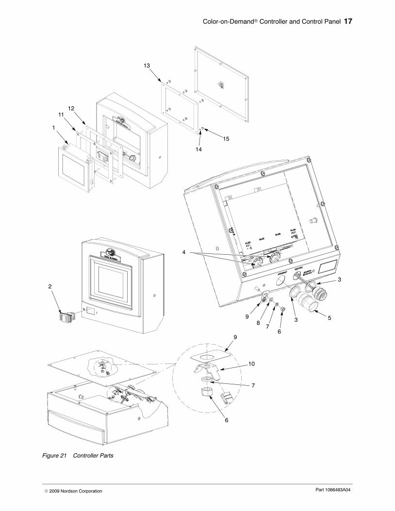
Controller Parts
See Figure 21.
Item Part Description Quantity Note— 1084529 CONTROLLER, interface, Prodigy color change 1
1 1084403 � TERMINAL, display, COD Generation II 1 A
2 322404 � SWITCH, rocker, DPST, dust-tight 1
3 939122 � SEAL, conduit fitting, 1/2 in., blue 2
4 984526 � NUT, lock, 1/2 in. conduit 2
5 324343 � CONNECTOR, conduit, straight, 1/2 in. 1
6 984702 � NUT, hex, M5, brass 4
7 983401 � WASHER, lock, split, M5, steel, zinc 4
8 983021 � WASHER, flat, 0.203 x 0.406 x 0.040 in., brass 1
9 240674 � TAG, ground 4
10 271221 � LUG, 45, double, 0.250, 0.438 in. 2NOTE A: Use Retrofit Kit 1084551 to replace Cimrex 69 display terminal with the Proface AGP3300 display
terminal.
Retrofit Kit
Item Part Description Quantity Note— 1084551 KIT, retrofit, display, COD Generation II 1
1 1084403 � TERMINAL, display, COD, Generation II 111 - - - - - - � PLATE, adapter with studs 112 - - - - - - � GASKET, adapter plate 113 - - - - - - � PLATE, adapter 114 983102 � WASHER, lock, E, SPT, #6, steel, zinc,
14451−CA4
15 984101 � NUT, hex, machine, #6−32, steel, zinc,14441−CA
4
Color-on-Demand� Controller and Control Panel 17
Part 1066483A04� 2009 Nordson Corporation
2
1
3
4
53
67
89
9
10
7
6
1112
13
14
15
Figure 21 Controller Parts
Color-on-Demand� Controller and Control Panel18
Part 1066483A04 � 2009 Nordson Corporation
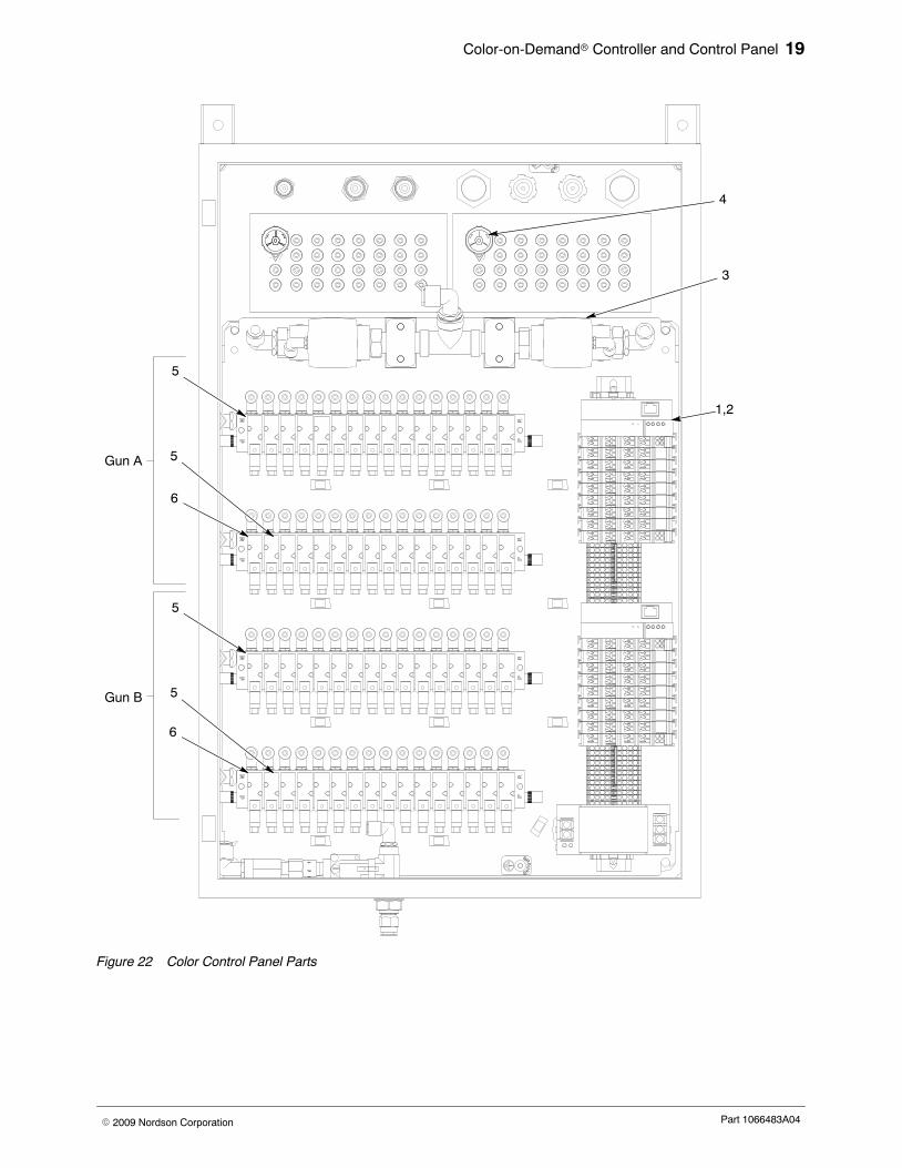
Color Change Control Panel Parts
See Figure 22.
Item Part Description Quantity Note— - - - - - - CONTROLLER, Prodigy, single or dual color
changer1
1 1084550 � CONTROL UNIT, dual pump color changer,PLC
1 A
2 1084489 � CONTROL UNIT, single pump color changer,PLC
1 A
3 303132 � VALVE, 3/4 in. NPT, air operated AR B
4 1095074 � SWITCH, pressure, N.O., 30 psi AR B5 1068324 � VALVE, solenoid, 3 port, 24V, N.O., w/o leads AR C6 1068325 � VALVE, solenoid, 3 port, 24V, N.C., w/o leads AR C
NS 173101 � TUBING, polyethylene, 8 mm x 6 mm, natural AR D
NS 900742 � TUBING, polyurethane, 6/4 mm, blue AR D
NS 900618 � TUBING, polyurethane, 8 mm OD, blue AR D
NS 900740 � TUBING, polyurethane, 10 mm OD, blue AR D
NS 226690 � TUBING, polyurethane, 12 mm OD, blue AR D
NOTE A: Select appropriate control unit for your system. Parts breakdown on following pages.
B: One required per gun.
C: 31 N.O. valves and 1 N.C. valve required per gun.
D: Order in increments of one foot.
AR: As Required
NS: Not Shown
Color-on-Demand� Controller and Control Panel 19
Part 1066483A04� 2009 Nordson Corporation
1,2
3
4
5
6
5
5
6
5
Gun A
Gun B
Figure 22 Color Control Panel Parts
Color-on-Demand� Controller and Control Panel20
Part 1066483A04 � 2009 Nordson Corporation
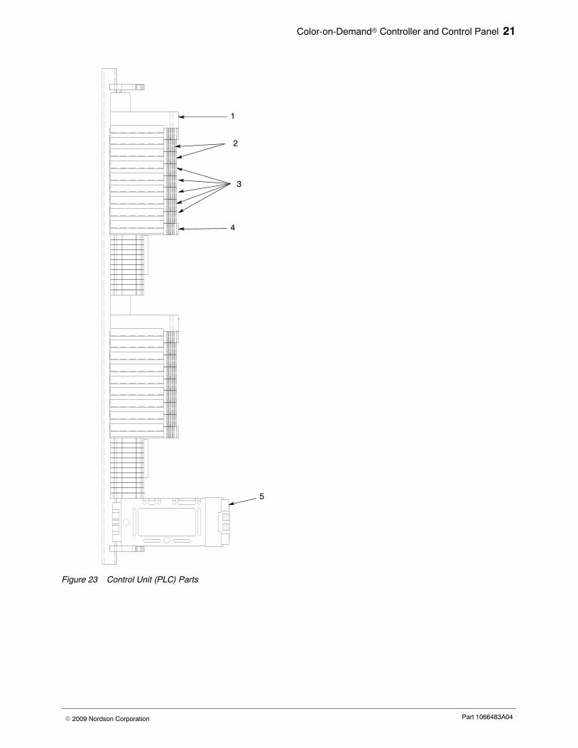
Control Unit (PLC) Parts
See Figure 23.
Item Part Description Quantity Note− 1084550 CONTROL UNIT, dual pump color changer, PLC 1
− 1084489 CONTROL UNIT, single pump color changer, PLC 1
1 1106849 � CONTROLLER, programmed, CODGeneration II
AR A, D
2 1064193 � MODULE, 8-channel digital input, Wago,750-430
AR B, D
3 1064195 � MODULE, 8-channel digital input, Wago,750-530
AR C, D
4 1064191 � MODULE, end, carrier, Wago, 750-600 1
5 1064192 � POWER SUPPLY, 90W, 24Vdc, 3.75 amps,DIN rail
1 D
NOTE A: Two required for dual control unit, one for single.
B: Four required for dual control unit, two for single.
C: Ten required for dual control unit, five for single.
D: Installation by a qualified Nordson service representative is recommended for these parts.
AR: As Required
NS: Not Shown
Color-on-Demand� Controller and Control Panel 21
Part 1066483A04� 2009 Nordson Corporation
3
2
1
4
5
Figure 23 Control Unit (PLC) Parts
Color-on-Demand� Controller and Control Panel22
Part 1066483A04 � 2009 Nordson Corporation
Ship-With Kit Parts
Part Description Quantity Note1067148 KIT, ship-with, Color-on-Demand system 1
1072866 � CABLE, Ethernet CAT5E, 50 ft 1
248375 � CONDUIT, flexible, bulk, 1/2 in. (50 ft) AR A
226690 � TUBING, polyurethane, 12/8 mm, blue (50 ft) AR A
1064948 � SWITCH, foot, air, 3-way, 100 psi AR900742 � TUBING, polyurethane, 6/4 mm, blue (100 ft) AR A972141 � CONNECTOR, male, 6 mm tube x 1/8 in. unithread 2911110 � UNION, bulkhead, 12 mm tube x 12 mm tube 2933071 � TERMINAL, ringtong, ins, 22−18, 10 1
NOTE A: Order replacements in increments of one foot.
AR: As Required
Color-on-Demand Controls 23
Part 1066483A03� 2008 Nordson Corporation
5 6
32
ENCLOSURE1064409
ADAPTER PLATE1083016
ETHERNET CABLE1072866
(FIELD INSTALLED)
PART OF1065029
GROUND WIRE302189
RECEPTACLE 6 PIN1065029 ROCKER SWITCH
322404
FROM ETHERNET INSULATIONDISPLACEMENT CONNECTOR1067145 (PART OF COLOR CHANGECONTROLLER
GR
EE
N/Y
ELL
OW
GREEN/YELLOW
RED
YELLOW
GR
EE
N/Y
ELL
OW YE
LLO
W
.50 STRAIGHTCONDUIT CONNECTOR
324343
TO BACK PLATEGROUND STUD
YELLOW
WHITE
GREEN
BLACK
GRAY
(ENCLOSURE GROUND) (ENCLOSURE GROUND)
USB
COM 1
COM 2
LANRJ−45
CONNECTOR
Pro−faceAPG3300−T1−D24P/N 1084403
5 6
32
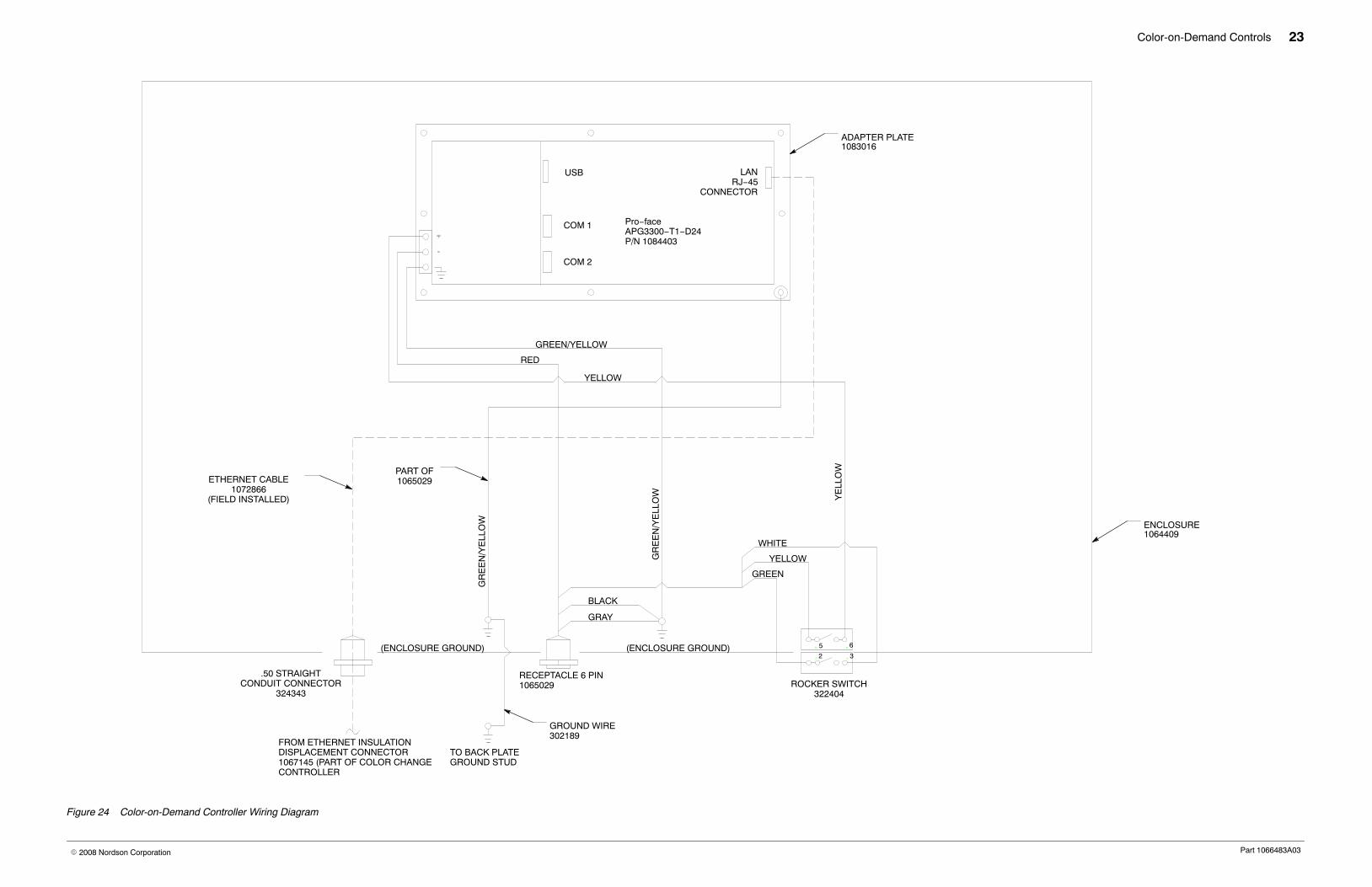
Figure 24 Color-on-Demand Controller Wiring Diagram
Color-on-Demand Controls 24
Part 1066483A03� 2008 Nordson Corporation
”AU
X 2
”P
UM
P C
AB
INE
TB
OT
TO
M
JF
RO
M P
UR
GE
RE
GU
LAT
OR
Y
FR
OM
FLO
WR
EG
ULA
TO
R Y
AIR
TA
NK
BU
LKH
EA
D
C
B
DE
CO
LOR
CH
AN
GE
MA
IN
C11AE
C10AE
C14AE
C13AE
C12AE
C9AE
C15AE
O P
61
A
FJ
D2BE
P1BE
P2BE
C25BE
C28BE
C27BE
C26BE
C13BE
C15BE
C14BE
C9BE
C12BE
C11BE
C10BE
FJ
G
D2AE
P1AE
P2AE
C27AE
C28AE
C26AE
C25AE
L
P1B
P
C11
BP
C14
BP
C6B
P
C15
BP
C7B
P
C13
BP
C5B
P
C12
BP
C4B
P
I
C9B
P
C1B
P
C10
BP
C2B
PC
3BP
C8B
P
D1B
P
C1AE
C2AE
D1AE
C5AE
C4AE
C7AE
C8AE
C6AE
C3AE
C22BE
C23BE
C24BE
C21BE
C18BE
C17BE
C20BE
C19BE
C6BE
C7BE
C8BE
C5BE
C1BE
C2BE
C4BE
C3BE
C16BED1BE
C24AE
C23AE
C21AE
C22AE
C20AE
C19AE
C18AE
C17AE
C16AE
L
N
C8A
P
D1A
P
P1A
P
M
C13
AP
C5A
P
H
C14
AP
C6A
P
C15
AP
C7A
P
C12
AP
C4A
P
C11
AP
C3A
P
C9A
P
C1A
P
C10
AP
C2A
P
K
FO
OT
SW
ITC
HS
OU
RC
E A
& B
CA
BIN
ET
RE
AR
C27
BP
C19
BP
CO
LOR
CH
AN
GE
DIS
TR
IBU
TIO
N M
AN
IFO
LD
P2B
P
C22
BP
SW
BR
TN
C23
BP
D2B
PC
28B
P
C21
BP
C20
BP
C25
BP
C17
BP
C26
BP
C18
BP
C24
BP
C16
BP
B
P1B
P1A
C24
AP
C16
AP
D2A
P
C21
AP
CO
LOR
CH
AN
GE
DIS
TR
IBU
TIO
N M
AN
IFO
LD
P2A
PS
WA
RT
N
C22
AP
C23
AP
C27
AP
C28
AP
C20
AP
C19
AP
C26
AP
C25
AP
C17
AP
C18
AP
A
1/2
NP
T P
IPE
PLU
G F
OR
1 P
UM
PC
ON
TR
OLL
ER (O
UT
OF
PO
SIT
ION
− F
ITT
ING
S S
HO
WN
RO
TAT
ED
FO
R C
LAR
ITY
)
(PU
MP
CO
NT
RO
L P
AN
EL)
(PU
MP
CO
NT
RO
L P
AN
EL)
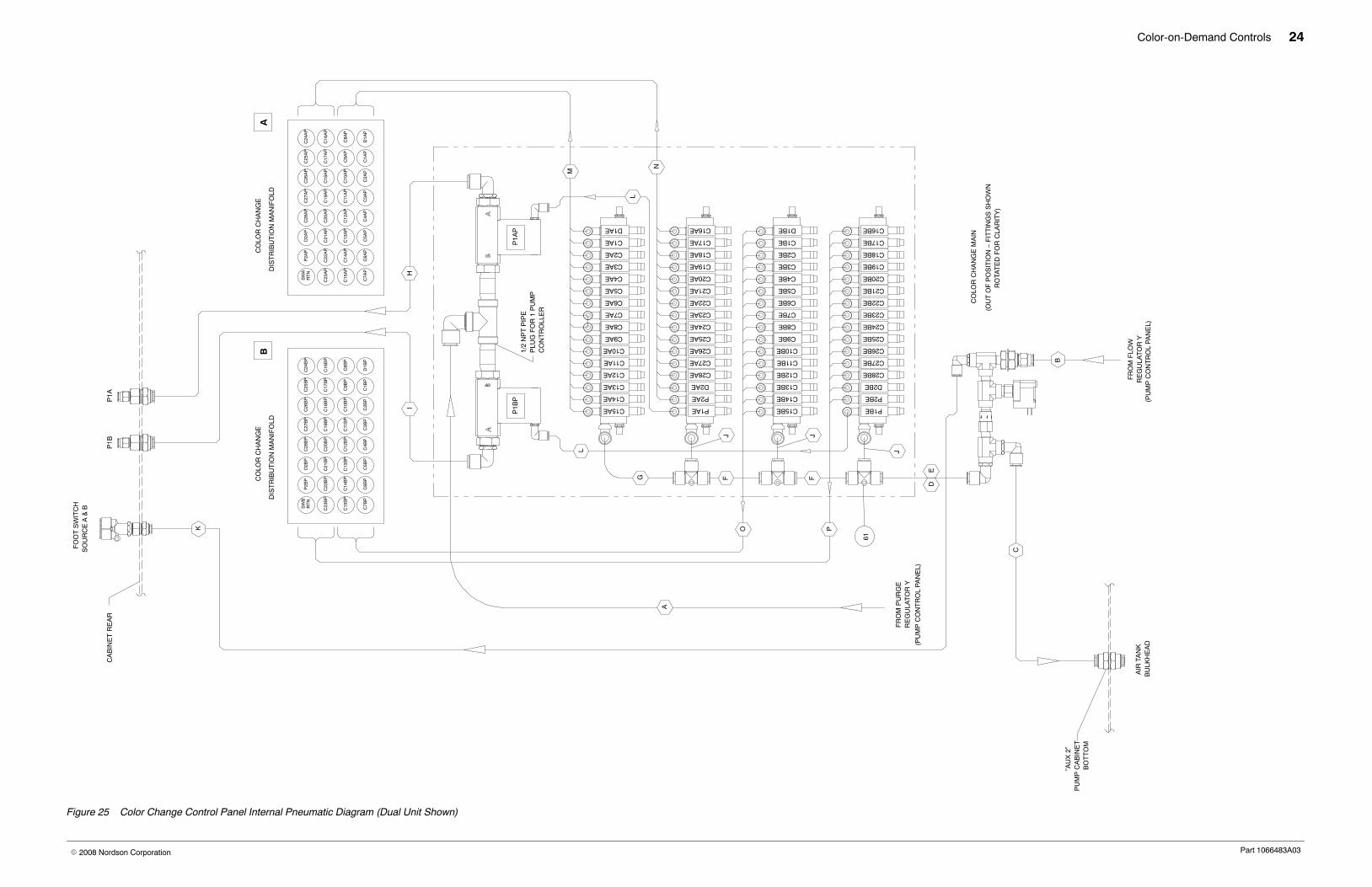
Figure 25 Color Change Control Panel Internal Pneumatic Diagram (Dual Unit Shown)
Color-on-Demand Controls 25
Part 1066483A03� 2008 Nordson Corporation
CO
LOR
CH
AN
GE
DIS
TR
IBU
TIO
N M
AN
IFO
LD
C28
P2
C26
C27
C24
C25
C22
C23
C20
C21
C10
C12
C14
C16
C18
C11
C13
C15
C17
D1
C2C4
C6
C8
C1
C3
C5
C7
C19 C9
D2
P1
C14
AP
C7A
P
C15
AP
C5A
PC
6AP
C13
AP
C22
AP
C23
AP
SW
AR
TN
C21
AP
P2A
PD
2AP
C25
AP
C17
AP
C9A
P
C1A
P
C11
AP
C3A
PC
4AP
C12
AP
C2A
P
C10
AP
C27
AP
C19
AP
C20
AP
C28
AP
C18
AP
C26
AP
D1A
P
C8A
P
C16
AP
C24
AP
R
S
TT
S
R
V W W
TO
PU
MP
1
(SE
E 1
0669
32)
TO
DU
MP
Q
P1A X
A
U
TO
PU
MP
2(S
EE
106
6932
)
U
RW
R
SW
S
TV
TO
DU
MP
CO
LOR
CH
AN
GE
DIS
TR
IBU
TIO
N M
AN
IFO
LD
B
D2
T
X
Q
C19
BP
C27
BP
C3B
P
C11
BP
C18
BP
C16
BP
C17
BP
C1B
P
C9B
P
D1B
P
C8B
P
C2B
P
C10
BP
C25
BP
C24
BP
C26
BP
C22
BP
C14
BP
C21
BP
C20
BP
C13
BP
C4B
P
C12
BP
C5B
PC
6BP
C28
BP
D2B
PP
2BP
C23
BP
C7B
P
C15
BP
SW
BR
TN
P1B
DU
MP
2
VA
LVE
CO
LOR
28−
P2
CO
LOR
10−
19
DU
MP
1−C
OLO
R9
DU
MP
2
VA
LVE
(D1 −
C9)
(C10
− C
19)
(C20
− P
2)
D1
C2C4
C6
C8
C1
C3
C5
C7
C9
C10
C12
C14
C16
C18
C11
C13
C15
C17
C19
C28
P2
C26
C27
C24
C25
C22
C23
C20
C21
P1
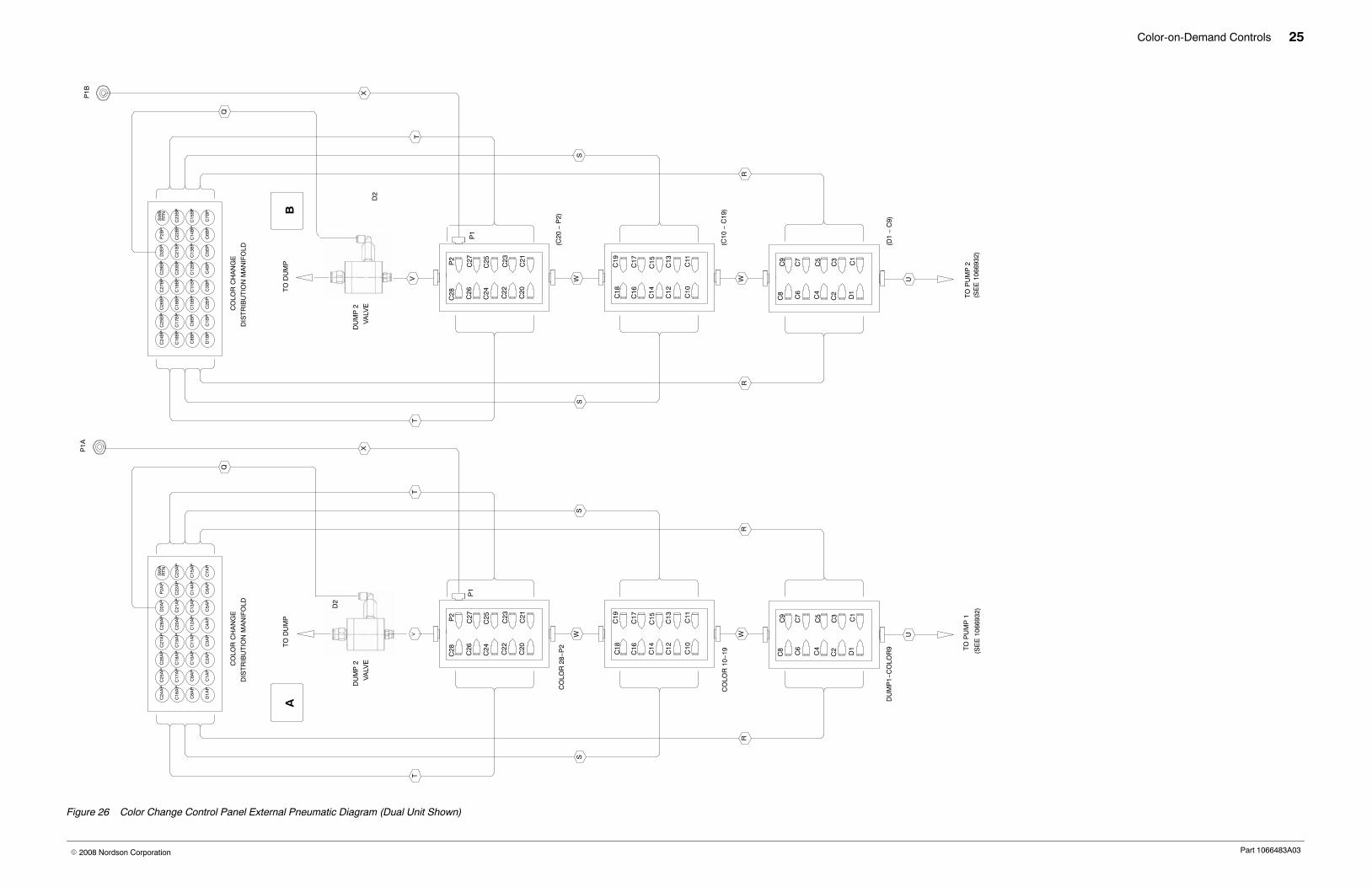
Figure 26 Color Change Control Panel External Pneumatic Diagram (Dual Unit Shown)
Color-on-Demand Controls 26
Part 1066483A03� 2008 Nordson Corporation
XXXPEXXXXX
PLC A
C20
BE
C4B
E
P2B
EC
14B
E
P1B
EC
15B
E
C25
BE
C26
BE
C28
BE
C27
BE
D2B
E
C22
BE
C21
BE
C24
BE
C23
BE
C9B
E
C11
BE
C13
BE
C12
BE
C10
BE
C7B
E
C8B
E
C6B
E
C5B
E
POWER
SUPPLY
C18
BE
C17
BE
C16
BE
C19
BE
C2B
E
C1B
E
D1B
E
C3B
E
PLC B
C4A
EC
20A
E
C14
AE
P2A
E
C15
AE
P1A
E
C10
AE
C13
AE
C12
AE
C11
AE
C25
AE
C28
AE
D2A
E
C26
AE
C27
AE
C22
AE
C24
AE
C23
AE
C21
AE
C9A
E
C6A
E
C8A
E
C7A
E
C5A
E
SWBRTN
C17
AE
C18
AE
C19
AE
C16
AE
C1A
E
C2A
E
C3A
E
D1A
E
SWARTN
NETWORKB
POWERB
NETWORKA
POWERA
(C.O.D. INTERFACE
POWER CABLE)
ENCLOSURE REAR)GND − (INSIDE
POWER B
DRAIN DRAIN
POWER A(C.O.D. INTERFACE
POWER CABLE)
BLU
E
BR
OW
N
14
13
24
23
RED
BLUEWHITE
BLACK
BLACK
REDBLUEWHITE
GREEN/YELLLOWBLUE
BROWN
BLU
E
WH
ITE
BLU
E
WH
ITE
NC (WHITE)
COM (BLUE)
TO: PRODIGYDUAL PUMP
CONTROL PANELB
TO: PRODIGYDUAL PUMP
CONTROL PANELA
PRODIGY COLOR CHANGESUB PANEL
PURGE PILOTMANIFOLD
COLOR CHANGEDISTRIBUTION MANIFOLD
CONTACT BLOCK
DETAIL A
AB
COLOR CHANGEDISTRIBUTION MANIFOLD
(SEE SCHEMATICS)
COMMUNICATIONHARNESS
COMMUNICATIONHARNESS
PRESSURE SWITCHHARNESS
FOOT SWITCH HARNESS FOOT SWITCH HARNESS
ETHERNET CROSSOVERCABLE 1065711
(FIELD INSTALL)
COLOR CHANGE CONTROLLERINTERFACE CABLE(SEE DETAIL A)
GR
EE
N/Y
ELL
OW
GND
(INSIDE PUMP
ENCLOSURE BOTTOM)
COLOR CHANGEPOWER CORD
(PART OF PUMP CONTROL PANEL)
BRN
GRNGRN/WHT
BRN/WHT
BLUORG/WHTORG
BLU/WHT
DETAIL B
SEE DETAIL B
ETHERNET INSULATIONDISPLACEMENT CONNECTORMODULE 1067145(FIELD INSTALL)
ETHERNET CONNECTORMODULE MOUNTING BOX1067146 (FIELD INSTALL)
100 FT. ETHERNET PATCH CABLE 1058222TO BE PULLED THRU CONDUIT TO PRODIGYCOLOR CHG CONTROLLER INTERFACE 1064954(FIELD INSTALL − TRIM TO LENGTH)
FIELD INSTALLATION
PRESSURE SWITCH(70 PSI)
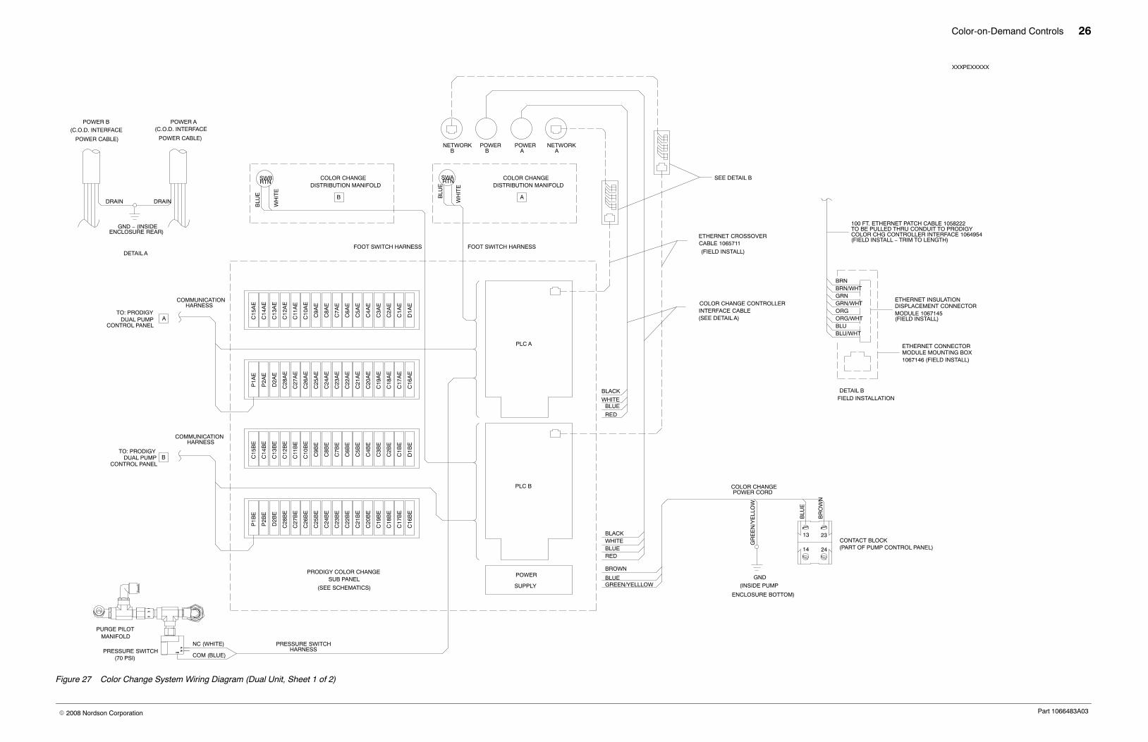
Figure 27 Color Change System Wiring Diagram (Dual Unit, Sheet 1 of 2)
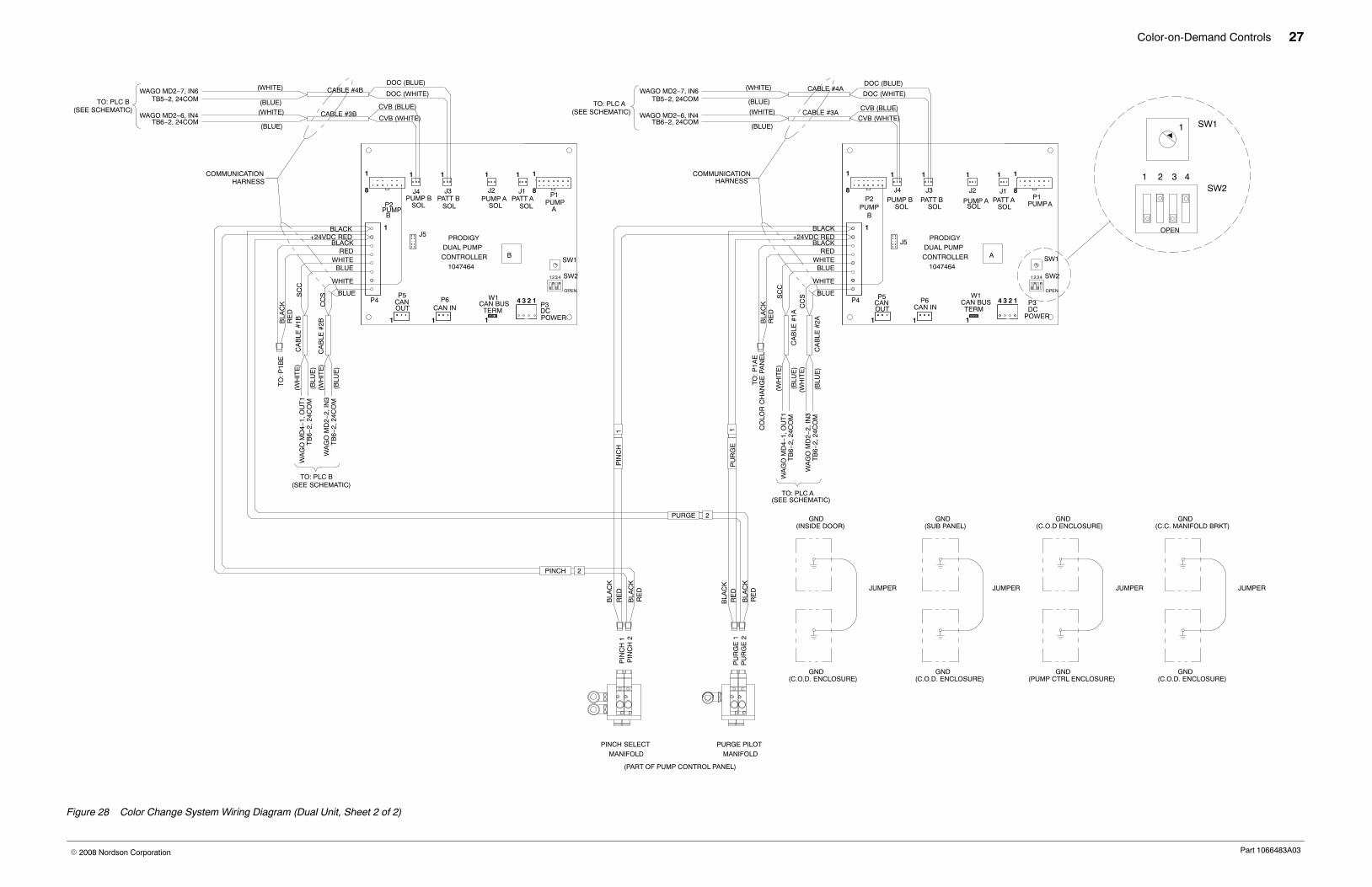
Color-on-Demand Controls 27
Part 1066483A03� 2008 Nordson Corporation
BLACK
1
8
1
4 3 2 1
8
1
J3PATT B
SOL
1
J4
PUMP B
1 1
J2
PUMP ASOL
1
J1PATT A
SOL
1
P4
J5
P2PUMP
B
P1PUMPA
P5CANOUT
P6CAN IN
W1CAN BUSTERM
1 1
P3DC
POWER
PIN
CH
1P
INC
H 2
PU
RG
E 1
PU
RG
E 2
+24VDC RED
RE
DB
LAC
K
RE
DB
LAC
K
PINCH SELECTMANIFOLD
RE
DB
LAC
K
RE
DB
LAC
K
PRODIGYDUAL PUMPCONTROLLER
1047464
PURGE PILOTMANIFOLD
COMMUNICATIONHARNESS
OPEN
21 43 SW2
SW1A
J5
P4
1
W1CAN BUS
TERM
P5CANOUT
P6CAN IN
1 1
PRODIGYDUAL PUMPCONTROLLER
1047464
P3DCPOWER
34 2 1
BSW1
P2PUMP
B
1
8
1
J3PATT B
SOL
J4PUMP B
1 1
J2PUMP A
SOL
1
P1PUMP
A
J1PATT A
SOL
1
8
1
TO
: P1B
EB
LAC
KR
ED
BLUEWHITE
BLACK+24VDC RED
RED
BLACK
(BLUE)
(WHITE)
(BLUE)
(WHITE)
CVB (BLUE)
CVB (WHITE)CABLE #3A
DOC (WHITE)
DOC (BLUE)CABLE #4A
COMMUNICATIONHARNESS
(WH
ITE
)
(BLU
E)
CA
BLE
#1B
TO: PLC B(SEE SCHEMATIC)
TO: PLC A(SEE SCHEMATIC)
(PART OF PUMP CONTROL PANEL)
(WH
ITE
)
(BLU
E)
CA
BLE
#2B
WHITE
BLUE
TO: PLC B(SEE SCHEMATIC)
CABLE #3B
CABLE #4B(WHITE)
(BLUE)
(BLUE)(WHITE)
CVB (BLUE)
CVB (WHITE)
DOC (BLUE)
DOC (WHITE)
BLUE
WHITE
BLACK
WHITEBLUE
RED
TO: PLC A(SEE SCHEMATIC)
CA
BLE
#2A
CA
BLE
#1A
TO
: P1A
E
(BLU
E)
(BLU
E)
(WH
ITE
)
(WH
ITE
)
BLA
CK
RE
D
JUMPER
GND(C.O.D. ENCLOSURE)
JUMPER
GND(C.O.D. ENCLOSURE)
GND(INSIDE DOOR)
GND(SUB PANEL)
GND(PUMP CTRL ENCLOSURE)
GND(C.O.D ENCLOSURE)
JUMPER
GND(C.C. MANIFOLD BRKT)
GND(C.O.D. ENCLOSURE)
JUMPER
PINCH 2
PURGE 2
PU
RG
E1
PIN
CH
1
SOL
OPEN
21 43 SW2
SOL
WAGO MD2−7, IN6TB5−2, 24COM
WAGO MD2−6, IN4TB6−2, 24COM
WAGO MD2−7, IN6TB5−2, 24COM
WAGO MD2−6, IN4TB6−2, 24COM
CO
LOR
CH
AN
GE
PA
NE
L
TB
6−2,
24C
OM
WA
GO
MD
2−2,
IN3
TB
6−2,
24C
OM
WA
GO
MD
4−1,
OU
T1
TB
6−2,
24C
OM
WA
GO
MD
2−2,
IN3
TB
6−2,
24C
OM
WA
GO
MD
4−1,
OU
T1
SC
C
CC
S
SW1
OPEN
21 43SW2
1
SC
C
CC
S
Figure 28 Color Change System Wiring Diagram (Dual Unit, Sheet 2 of 2)
Color-on-Demand Controls 28
Part 1066483A03� 2008 Nordson Corporation
FROM
PUMP
CONTROL
BOX
POWER
CABLE
1000 (HOT,BROWN)
1010 (NEUT,BLUE)
1020 (GND,GREEN\YELLOW)
PWR1, POWER SUPPLY
OMRON
L
N
G
100−240VAC
DC ON
VR ADJ
24VDC5A
−V
+V
S8VS12
024
1030 (GND,GREEN\YELLOW, 16 GA)
(GREEN \
YELLOW)
DIN RAIL CHASSIS
GROUND
TB1A
1070 (24COM,BLACK)
1080 (24VDC,RED)
122122
10801070
121
116
120
119
118
117
115
114
113
112
107
111
110
108
109
106
105
104
103
100
102
101
143
138
142
141
140
139
137
136
135
134
129
133
132
130
131
128
127
126
125
122
124
123
CCSA (BLUE)
CVBA (BLUE)
SCCA (BLUE)
DOCA (BLUE)
1120 (BLACK)
PS1 (WHITE)
1080 (24VDC,RED)
SW1A (RED)
(BLUE)
TB12A
(BLUE)
TB11A
(BLUE)
TB10A
(BLUE)
TB9A
(BLUE)
TB8A
(BLUE)
TB7A
(BLUE)
TB6A
(BLUE)
TB5A
(GRAY)
TB4A
(GRAY)
TB3A
(GRAY)
TB2A
D2AE (BLACK)D1AE (BLACK)C28AE (BLACK)C27AE (BLACK)C26AE (BLACK)C25AE (BLACK)C24AE (BLACK)
C23AE (BLACK)C22AE (BLACK)C21AE (BLACK)C20AE (BLACK)C19AE (BLACK)C18AE (BLACK)C17AE (BLACK)C16AE (BLACK)C15AE (BLACK)C14AE (BLACK)C13AE (BLACK)C12AE (BLACK)C11AE (BLACK)C10AE (BLACK)C9AE (BLACK)C8AE (BLACK)C7AE (BLACK)C6AE (BLACK)C5AE (BLACK)
C2AE (BLACK)
C4AE (BLACK)C3AE (BLACK)
C1AE (BLACK)P2AE (BLACK)
24COM (BLACK)
+24V SW1A−5 (RED)
SW1A−2 (WHITE)
SW1A−3 (BLUE)
CABLE
POWER
DISPLAY ”A”
FROM
4
3
2
1
4
3
2
1
4
3
2
1
4
3
2
1
4
3
2
1
4
3
2
1
4
3
2
1
4
3
2
1
4
3
2
1
4
3
2
1
4
3
2
1
10701080
200 200
121121
RSIA(WHITE)
23
13
BROWN
BLUE
AC POWERSWITCH
GREEN\YELLOW
GROUND STUD
USE 8 POS.
JUMPER
GROUND (BARE)
STUD
SUB PANEL
ENCLOSURE
STUD
BRAIDED JUMPER
BRAIDED JUMPER
STUD
ENCLOSURE
DOOR
STUD
BRAIDED JUMPER
121
1120
122
1071 (BLACK)
1120 (BLACK)
1011
(B
LUE
)
1001
(B
RO
WN
)
CRI
Figure 29 Color-on-Demand Control Panel Schematic (Dual Unit, Sheet 1 of 10)
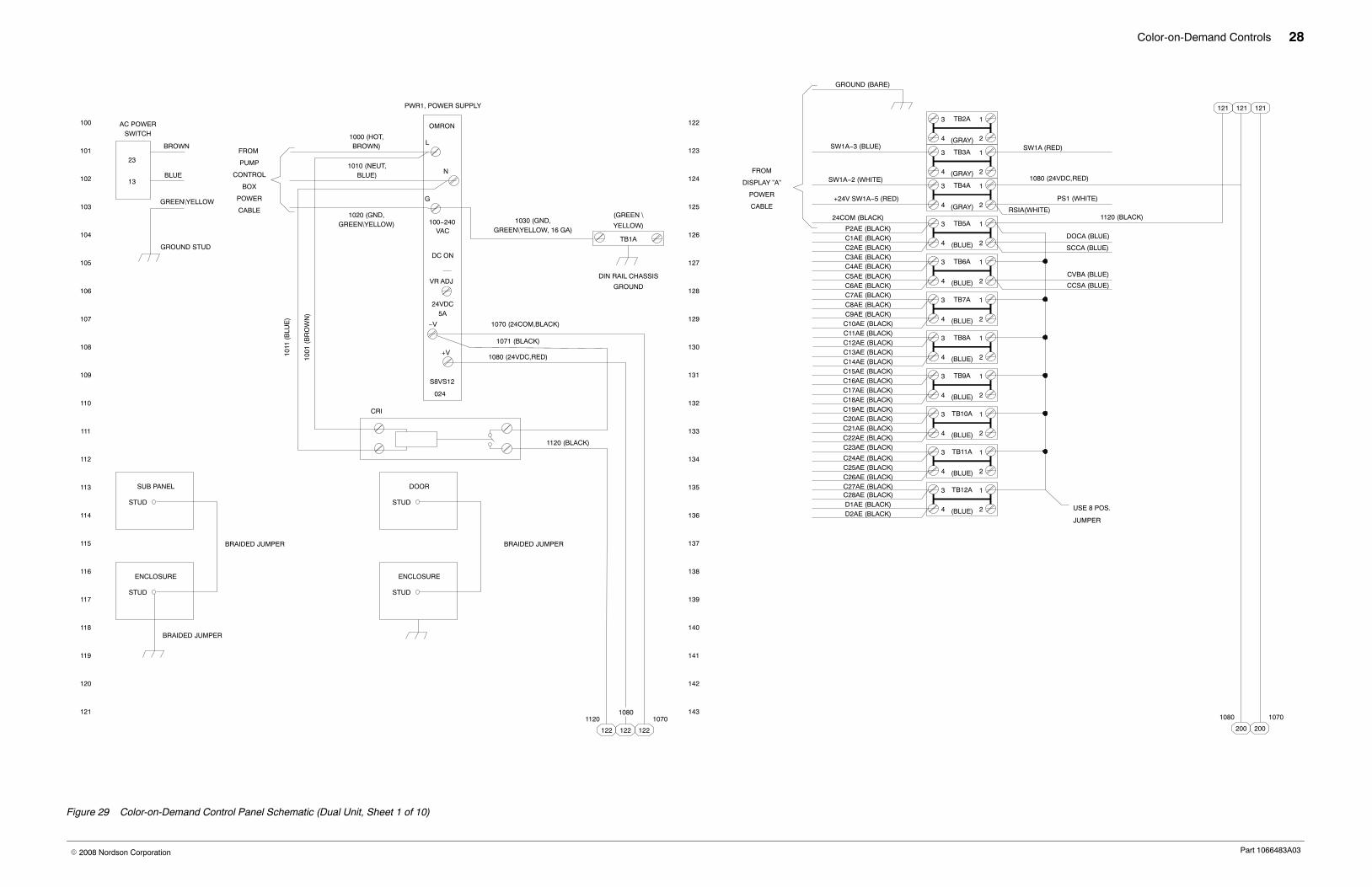
Color-on-Demand Controls 29
Part 1066483A03� 2008 Nordson Corporation
221
216
220
219
218
217
215
214
213
212
207
211
210
208
209
206
205
204
203
200
202
201
243
238
242
241
240
239
237
236
235
234
229
233
232
230
231
228
227
226
225
222
224
MD2A, 8 PT. SOURCE
430
1,IN1
750−
2,IN3
3,IN5
4,IN7
5,IN2
6,IN4
7,IN6
8,IN8
INPUT, POS. 1
SW1A (RED)
RS1A (BLUE)
CCSA (BLUE)
CCSA (WHITE)
CVBA (BLUE)
CVBA (WHITE)
PS1 (BLUE)
DOCA (BLUE)
DOCA (WHITE)
FROMPUMP
FROMPUMP
PS1 (WHITE)
CABLE #2A
CABLE #3A
COM
PRESSURE SWITCH
PS1 NC
CABLE #4A
11
223
PS1 (BLACK)
1080 1070
143143
TB1A
1030 (GND,GREEN/YELLOW)
1070 (24COM,BLACK)
1080 (24VDC,RED)
BLACK
RED
24V
750−
842
+
_
0V
+
_
WA
GO
I/O
SY
ST
EM
BUS CONTROLLER
MD1A, ETHERNET FIELD−
PS2A
FOOT SWITCH A
PRESSURE SWITCHRS1A (WHITE) 2 2
INPUT 7 SPARE 1
INPUT 8 SPARE 2
MD3A, 8 PT. SOURCE
1,IN1
5,IN2
2,IN3
6,IN4
3,IN5
7,IN6
4,IN7
8,IN8
750−
430
RS2A
BIT5A MSB
BIT4A
BIT3A
BIT2A
BIT1A LSB
SPARE 3
SPARE 4
REMOTE PLC INTERFACE
COLOR CHANGE
SELECT & STROBE
RJ−45
MALE
(DESIGNATED INPUTS)
VIA ”AUX. 1”
CONTROLPANEL
CONTROLPANEL
Figure 30 Color-on-Demand Control Panel Schematic (Dual Unit, Sheet 2 of 10)
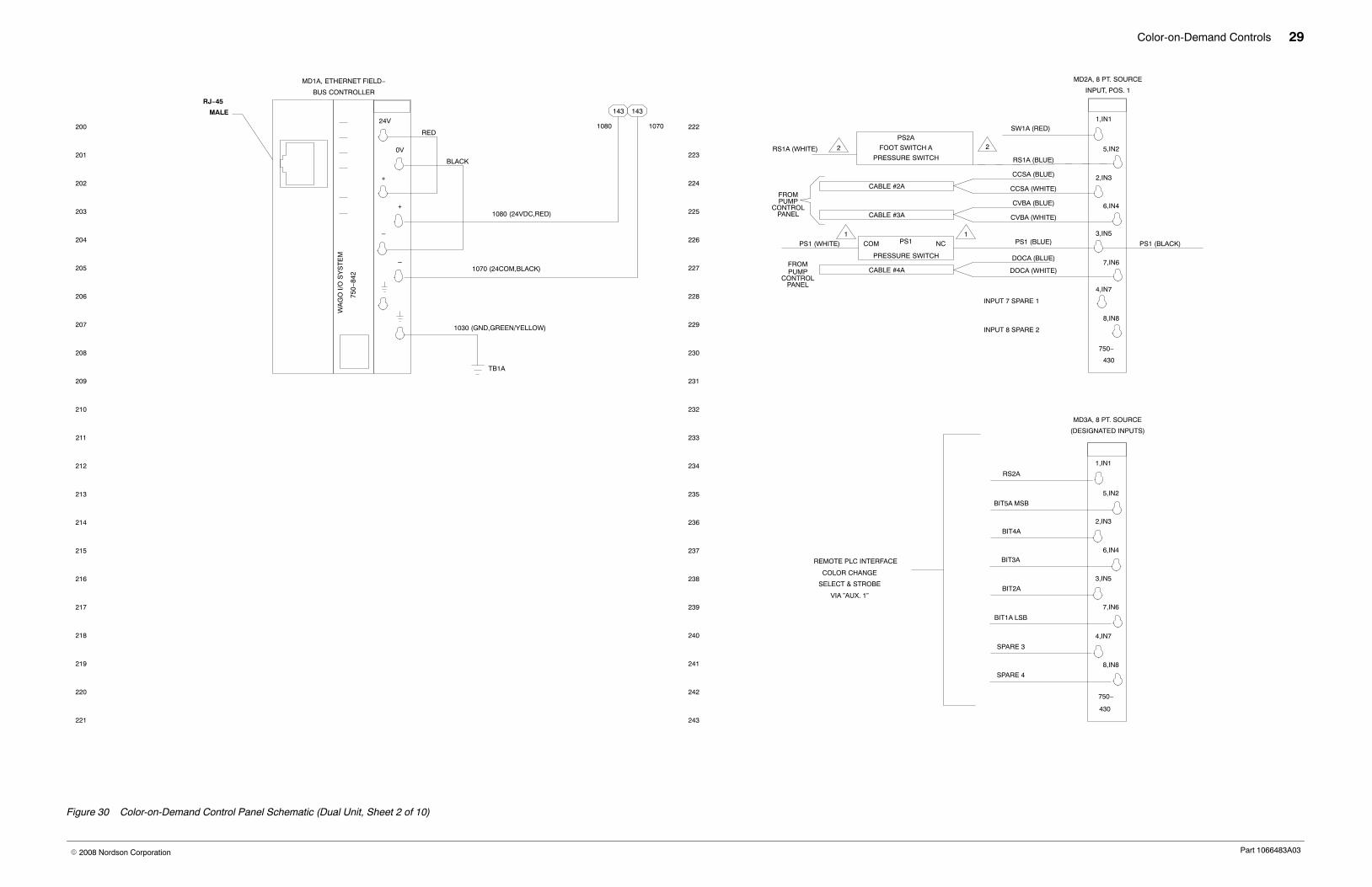
Color-on-Demand Controls 30
Part 1066483A03� 2008 Nordson Corporation
321
316
320
319
318
317
315
314
313
312
307
311
310
308
309
306
305
304
303
300
302
301
343
338
342
341
340
339
337
336
335
334
329
333
332
330
331
328
327
326
325
322
324
323
FROM PUMPCABLE #1A
SCCA (BLUE)
SCCA (WHITE)
MD4A, 8 PT. SOURCE
OUTPUT, POS. 2
RM1A (RED)
SPARE(CCD)
P2AE (RED)
C28AE (RED)
C27AE (RED)
C26AE (RED)
C25AE (RED)
P2AE
VALVE
C28BE
VALVE
C27AE
VALVE
C26AE
VALVE
C25AE
VALVE
C28AE (BLACK)
C27AE (BLACK)
C26AE (BLACK)
C25AE (BLACK)
P2AE (BLACK)
1,OUT1
5,OUT2
2,OUT3
6,OUT4
3,OUT5
7,OUT6
4,OUT7
8,OUT8
750−
530
MD5A, 8 PT. SOURCE
OUTPUT, POS. 3
1,OUT1
5,OUT2
2,OUT3
7,OUT6
3,OUT5
6,OUT4
4,OUT7
8,OUT8
750−
530
C24AE (BLACK) C24AE
VALVE
C24AE (RED)
C23AE (BLACK) C23AE
VALVE
C23AE (RED)
C22AE (BLACK)
C21AE (BLACK)
C20AE (BLACK)
C19AE (BLACK)
C18AE (BLACK)
C17AE (BLACK)
C22AE
VALVE
C21AE
VALVE
C20AE
VALVE
C19AE
VALVE
C18AE
VALVE
C17AE
VALVE
C22AE (RED)
C21AE (RED)
C20AE (RED)
C19AE (RED)
C18AE (RED)
C17AE (RED)
MD6A, 8 PT. SOURCE
OUTPUT,POS. 4
C16AE (BLACK)
C15AE (BLACK)
C14AE (BLACK)
C13AE (BLACK)
C12AE (BLACK)
C11AE (BLACK)
C10AE (BLACK)
C9AE (BLACK)
C16AE
VALVE
C15AE
VALVE
C14AE
VALVE
C13AE
VALVE
C12AE
VALVE
C11AE
VALVE
C10AE
VALVE
C9AE
VALVE
C16AE (RED)
C15AE (RED)
C14AE (RED)
C13AE (RED)
C12AE (RED)
C11AE (RED)
C9AE (RED)
C10AE (RED)
1,OUT1
5,OUT2
2,OUT3
6,OUT4
3,OUT5
7,OUT6
4,OUT7
8,OUT8
750−
530
MD7A, 8 PT. SOURCE
OUTPUT, POS. 5
5.OUT2
2,OUT3
1,OUT1
6,OUT4
3,OUT5
7,OUT6
4,OUT7
8,OUT8
750−
530
C7AE (BLACK)
C8AE (BLACK)
C6AE (BLACK)
C5AE (BLACK)
C3AE (BLACK)
C2AE (BLACK)
C1AE (BLACK)
C4AE (BLACK)
C8AE
VALVE
C7AE
VALVE
C6AE
VALVE
C5AE
VALVE
C4AE
VALVE
C3AE
VALVE
C2AE
C1AE
VALVE
VALVE
C7AE (RED)
C8AE (RED)
C6AE (RED)
C5AE (RED)
C4AE (RED)
C3AE (RED)
C2AE (RED)
C1AE (RED)
4. 4.
FLOW CONTROLBOARD A
Figure 31 Color-on-Demand Control Panel Schematic (Dual Unit, Sheet 3 of 10)
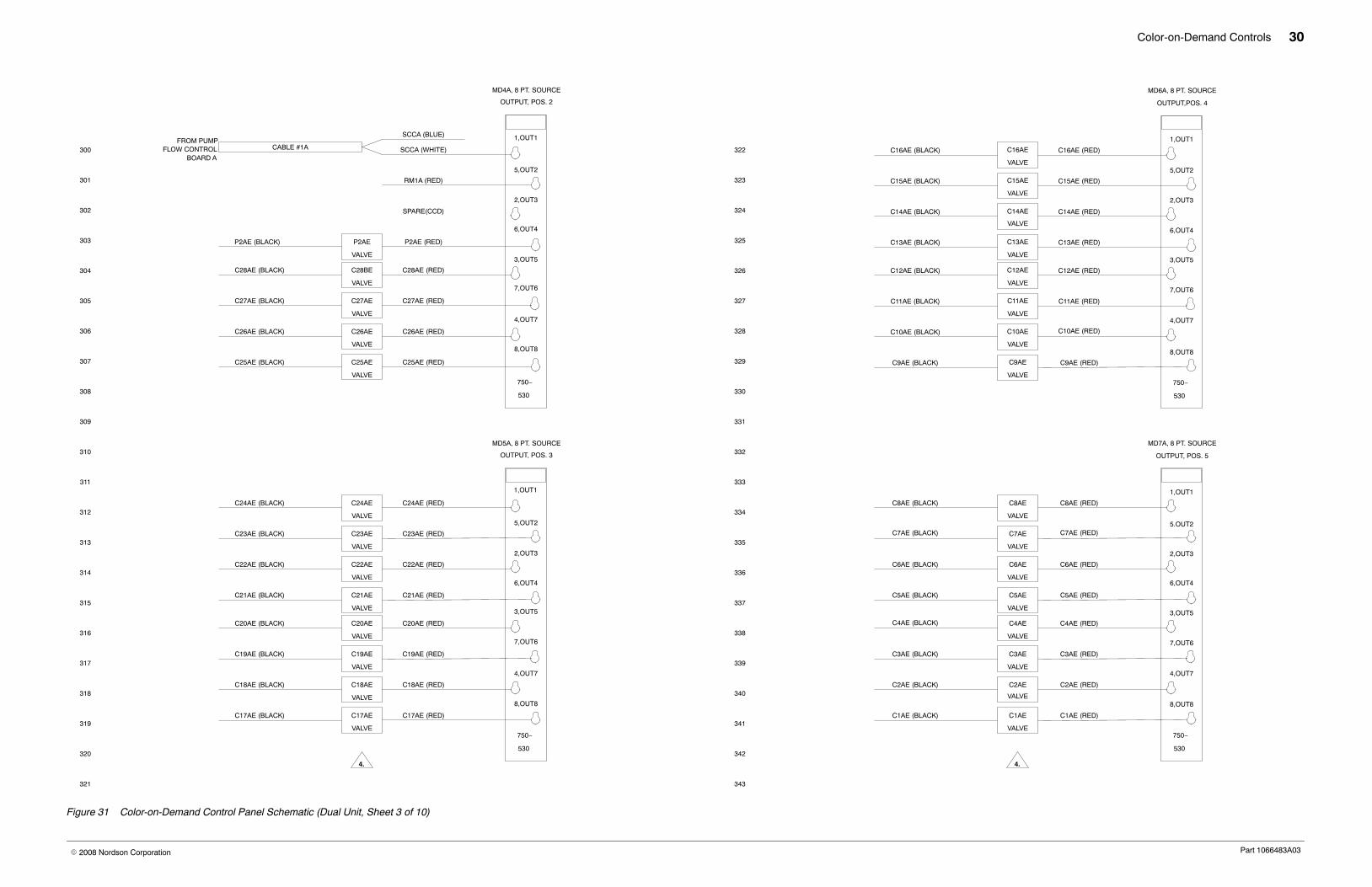
Color-on-Demand Controls 31
Part 1066483A03� 2008 Nordson Corporation
421
416
420
419
418
417
415
414
413
412
407
411
410
408
409
406
405
404
403
400
402
401
443
438
442
441
440
439
437
436
435
434
429
433
432
430
431
428
427
426
425
422
424
423
MD8A, 8 PT.SOURCE
OUTPUT, POS. 6
1,OUT1
5,OUT2
6,OUT4
3,OUT5
2,OUT3
7,OUT6
4,OUT7
8,OUT8
750−
530
D1AE (BLACK)
D2AE (BLACK)
D1AE
VALVE
D2AE
VALVE
D1AE (RED)
D2AE (RED)
OUTPUT 35 SPARE 1
OUTPUT 36 SPARE 2
OUTPUT 37 SPARE 3
OUTPUT 38 SPARE 4
OUTPUT 39 SPARE 5
OUTPUT 40 SPARE 6
MD9A,BUS END
POS. 7
1
5
2
6
3
7
4
8
750−
600
4.
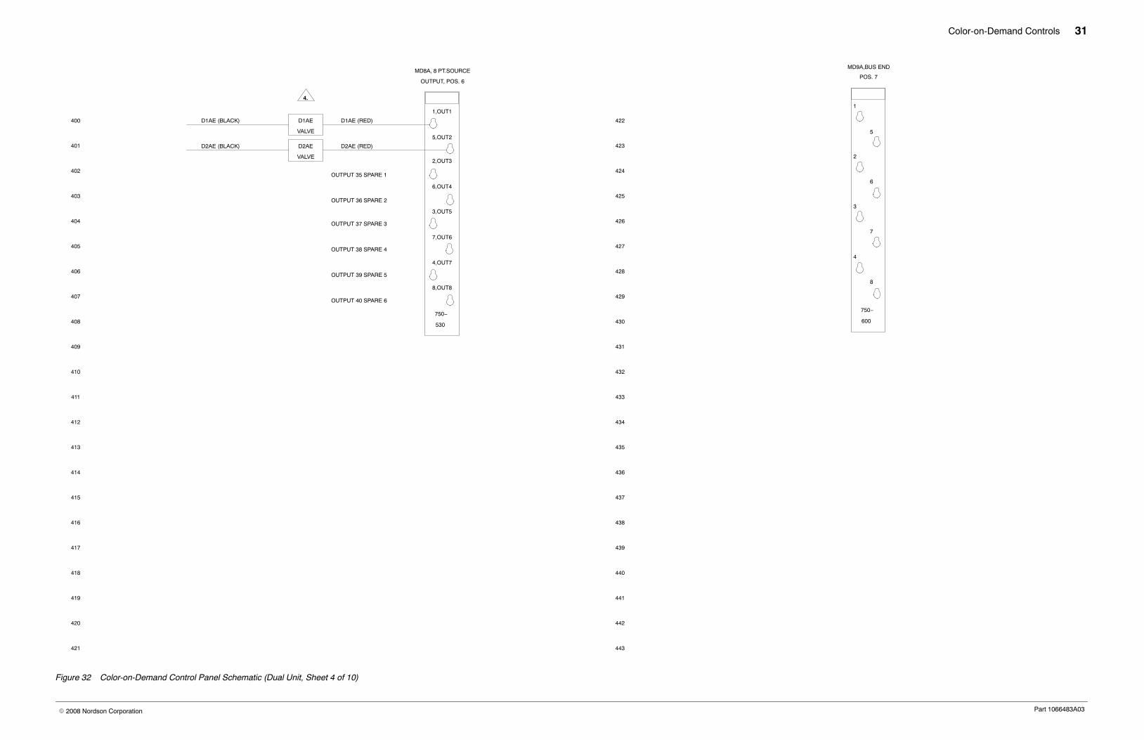
Figure 32 Color-on-Demand Control Panel Schematic (Dual Unit, Sheet 4 of 10)
Color-on-Demand Controls 32
Part 1066483A03� 2008 Nordson Corporation
1030 (GND,GREEN\YELLOW)
(GREEN \
YELLOW)
DIN RAIL CHASSIS
GROUND
TB1B
521
516
520
519
518
517
515
514
513
512
507
511
510
508
509
506
505
504
503
500
502
501
543
538
542
541
540
539
537
536
535
534
529
533
532
530
531
528
527
526
525
522
524
523
CCSB (BLUE)
CVBB (BLUE)
SCCB (BLUE)
DOCB (BLUE)
(BLUE)
TB12B
(BLUE)
TB11B
(BLUE)
TB10B
(BLUE)
TB9B
(BLUE)
TB8B
(BLUE)
TB7B
(BLUE)
TB6B
(BLUE)
TB5B
(GRAY)
TB4B
(GRAY)
TB3B
(GRAY)
TB2B
D2BE (BLACK)D1BE (BLACK)C28BE (BLACK)C27BE (BLACK)C26BE (BLACK)C25BE (BLACK)C24BE (BLACK)
C23BE (BLACK)C22BE (BLACK)C21BE (BLACK)C20BE (BLACK)C19BE (BLACK)C18BE (BLACK)C17BE (BLACK)C16BE (BLACK)C15BE (BLACK)C14BE (BLACK)C13BE (BLACK)C12BE (BLACK)C11BE (BLACK)C10BE (BLACK)C9BE (BLACK)C8BE (BLACK)C7BE (BLACK)C6BE (BLACK)C5BE (BLACK)
C2BE (BLACK)
C4BE (BLACK)C3BE (BLACK)
C1BE (BLACK)P2BE (BLACK)
CABLE
POWER
DISPLAY ”B”
FROM
4
3
2
1
4
3
2
1
4
3
2
1
4
3
2
1
4
3
2
1
4
3
2
1
4
3
2
1
4
3
2
1
4
3
2
1
4
3
2
1
4
3
2
1
RSIB(WHITE)
PWR1 GND
USE 8 POS.
JUMPER
GROUND (BARE)
SW1B−3 (BLUE)
SW1B−2 (WHITE)
+24V SW1B−5 (RED)
24COM (BLACK)
SW1B (RED)
1080 (24VDC,RED)
1120 (BLACK)
121 121
600600
1080 1070
121
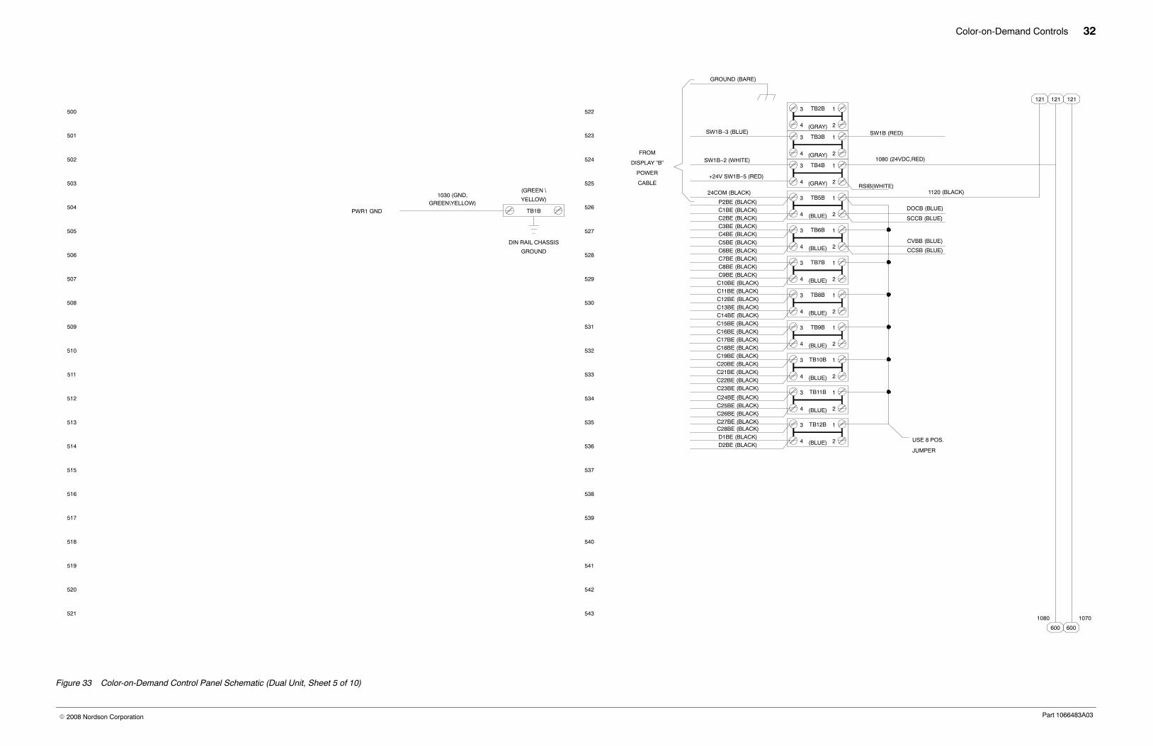
Figure 33 Color-on-Demand Control Panel Schematic (Dual Unit, Sheet 5 of 10)
Color-on-Demand Controls 33
Part 1066483A03� 2008 Nordson Corporation
621
616
620
619
618
617
615
614
613
612
607
611
610
608
609
606
605
604
603
600
602
601
643
638
642
641
640
639
637
636
635
634
629
633
632
630
631
628
627
626
625
622
624
MD2B, 8 PT. SOURCE
430
1,IN1
750−
2,IN3
3,IN5
4,IN7
5,IN2
6,IN4
7,IN6
8,IN8
INPUT, POS. 1
SW1B (RED)
RS1B (BLUE)
CCSB (BLUE)
CCSB (WHITE)
CVBB (BLUE)
CVBB (WHITE)
DOCB (BLUE)
DOCB (WHITE)
FROMPUMP
FROMPUMP
CABLE #2B
CABLE #3B
CABLE #4B
623
PS1 (BLACK)
1080 1070
543543
TB1B
24V
750−
842
+
_
0V
+
_
WA
GO
I/O
SY
ST
EM
BUS CONTROLLER
MD1B, ETHERNET FIELD−
PS2B
FOOT SWITCH B
PRESSURE SWITCH
RS1B (WHITE) 2 2
INPUT 7 SPARE 1
INPUT 8 SPARE 2
1,IN1
5,IN2
2,IN3
6,IN4
3,IN5
7,IN6
4,IN7
8,IN8
750−
430
RS2B
BIT5B MSB
BIT4B
BIT3B
BIT2B
BIT1B LSB
SPARE 3
SPARE 4
REMOTE PLC INTERFACE
COLOR CHANGE
SELECT & STROBE
RJ−45
MALE
1080 (24VDC,RED)
1070 (24COM,BLACK)
1030 (GND,GREEN/YELLOW)
BLACK
RED
(DESIGNATED INPUTS)
MD3B, 8 PT. SOURCE
VIA ”AUX. 1”
CONTROLPANEL
CONTROLPANEL
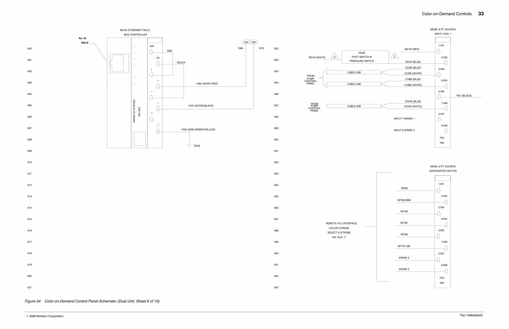
Figure 34 Color-on-Demand Control Panel Schematic (Dual Unit, Sheet 6 of 10)
Color-on-Demand Controls 34
Part 1066483A03� 2008 Nordson Corporation
721
716
720
719
718
717
715
714
713
712
707
711
710
708
709
706
705
704
703
700
702
701
743
738
742
741
740
739
737
736
735
734
729
733
732
730
731
728
727
726
725
722
724
723
FROM PUMPCABLE #1B
SCCB (BLUE)
SCCB (WHITE)
MD4B, 8 PT. SOURCE
OUTPUT, POS. 2
RM1B (RED)
SPARE(EV12)
P2BE (RED)
C28BE (RED)
C27BE (RED)
C26BE (RED)
C25BE (RED)
P2BE
VALVE
C28BE
VALVE
C27BE
VALVE
C26BE
VALVE
C25BE
VALVE
C28BE (BLACK)
C27BE (BLACK)
C26BE (BLACK)
C25BE (BLACK)
P2BE (BLACK)
1,OUT1
5,OUT2
2,OUT3
6,OUT4
3,OUT5
7,OUT6
4,OUT7
8,OUT8
750−
530
MD5B, 8 PT. SOURCE
OUTPUT, POS. 3
1,OUT1
5,OUT2
2,OUT3
7,OUT6
3,OUT5
6,OUT4
4,OUT7
8,OUT8
750−
530
C24BE (BLACK) C24BE
VALVE
C24BE (RED)
C23BE (BLACK) C23BE
VALVE
C23BE (RED)
C22BE (BLACK)
C21BE (BLACK)
C20BE (BLACK)
C19BE (BLACK)
C18BE (BLACK)
C17BE (BLACK)
C22BE
VALVE
C21BE
VALVE
C20BE
VALVE
C19BE
VALVE
C18BE
VALVE
C17BE
VALVE
C22BE (RED)
C21BE (RED)
C20BE (RED)
C19BE (RED)
C18BE (RED)
C17BE (RED)
MD6B, 8 PT. SOURCE
OUTPUT,POS. 4
C16BE (BLACK)
C15BE (BLACK)
C14BE (BLACK)
C13BE (BLACK)
C12BE (BLACK)
C11BE (BLACK)
C10BE (BLACK)
C9BE (BLACK)
C16BE
VALVE
C15BE
VALVE
C14BE
VALVE
C13BE
VALVE
C12BE
VALVE
C11BE
VALVE
C10BE
VALVE
C9BE
VALVE
C16BE (RED)
C15BE (RED)
C14BE (RED)
C13BE (RED)
C12BE (RED)
C11BE (RED)
C9BE (RED)
C10BE (RED)
1,OUT1
5,OUT2
2,OUT3
6,OUT4
3,OUT5
7,OUT6
4,OUT7
8,OUT8
750−
530
MD7B, 8 PT. SOURCE
OUTPUT, POS. 5
5.OUT2
2,OUT3
1,OUT1
6,OUT4
3,OUT5
7,OUT6
4,OUT7
8,OUT8
750−
530
C7BE (BLACK)
C8BE (BLACK)
C6BE (BLACK)
C5BE (BLACK)
C3BE (BLACK)
C2BE (BLACK)
C1BE (BLACK)
C4BE (BLACK)
C8BE
VALVE
C7BE
VALVE
C6BE
VALVE
C5BE
VALVE
C4BE
VALVE
C3BE
VALVE
C2BE
C1BE
VALVE
VALVE
C7BE (RED)
C8BE (RED)
C6BE (RED)
C5BE (RED)
C4BE (RED)
C3BE (RED)
C2BE (RED)
C1BE (RED)
4. 4.
FLOW CONTROLBOARD B
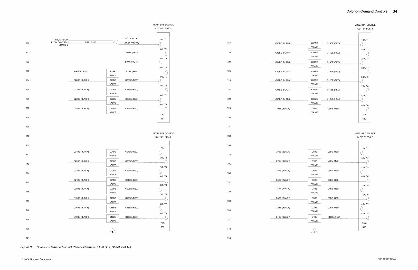
Figure 35 Color-on-Demand Control Panel Schematic (Dual Unit, Sheet 7 of 10)

Color-on-Demand Controls 35
Part 1066483A03� 2008 Nordson Corporation
821
816
820
819
818
817
815
814
813
812
807
811
810
808
809
806
805
804
803
800
802
801
843
838
842
841
840
839
837
836
835
834
829
833
832
830
831
828
827
826
825
822
824
823
MD8B, 8 PT.SOURCE
OUTPUT, POS. 6
1,OUT1
5,OUT2
6,OUT4
3,OUT5
2,OUT3
7,OUT6
4,OUT7
8,OUT8
750−
530
D1BE (BLACK)
D2BE (BLACK)
D1BE
VALVE
D2BE
VALVE
D1BE (RED)
D2BE (RED)
OUTPUT 35 SPARE 1
OUTPUT 36 SPARE 2
OUTPUT 37 SPARE 3
OUTPUT 38 SPARE 4
OUTPUT 39 SPARE 5
OUTPUT 40 SPARE 6
MD9B,BUS END
POS. 7
1
5
2
6
3
7
4
8
750−
600
4.
Figure 36 Color-on-Demand Control Panel Schematic (Dual Unit, Sheet 8 of 10)
Color-on-Demand Controls 36
Part 1066483A03� 2008 Nordson Corporation
JUMPER JUMPER
L N GRN
−V +V
VRADJ
DC ON
S8VS12, 24
ON
LINK
TXD/RXD
ERROR
I/O
USR
ERROR
TXD/RXD
LINK
ON
USR
I/O
1 5 1 5 1 5 1 5 1 5 1 5 1 5 1 5
2 6
3 7
4 8
2 6
73
4 8
2 6
73
4 8
2 6
73
4 8
2 6
73
4 8
2 6
73
4 8
2 6
73
4 8
2 6
73
4 8
1 5 1 5 1 5 1 5 1 5 1 5 1 5 1 5
6262626262626262
3 7 3 7 3 7 3 7 3 7 3 7 3 7 3 7
8484848484848484
1
2
3
4
1
2
3
4
1
2
3
4
1
2
3
4
1
2
3
4
1
2
3
4
1
2
3
4
1
2
3
4
1
2
3
4
1
2
3
4
1
2
3
4
1
2
3
4
1
2
3
4 4
3
2
1 1
2
3
4 4
3
2
1 1
2
3
4 4
3
2
1 1
2
3
4 4
3
2
1 1
2
3
4 4
3
2
1 1
2
3
4
WA
GO−
I/O
SY
ST
EM
750−
842
WA
GO−
I/O
SY
ST
EM
750−
842
750−430 750−430 750−530 750−530 750−530 750−530 750−530 750−600 750−600750−530750−530750−530750−530750−530750−430750−430
MD2A
MD3A
MD4A MD6A
MD5A MD7A
MD8A
MD9A MD9B
MD8B
MD7BMD5B
MD6BMD4B
MD3B
MD2B
TB12A
TB11A
TB10A
TB9A
TB8A
TB7A
TB6A
TB1ATB2A
TB3A
TB4A
TB5A
EC1A
TB6B
TB7B
TB8B
TB9B
TB10B
TB11B
TB12B
TB5B
TB4B
TB3B
TB2B
DIN RAIL
LAYOUT DIAGRAM PLC A AND B
PLC ”A” PLC ”B”
4
3
2
1
TB1BEB1
MD1A MD1B
EB2
POWERSUPPLY
2
EC2BCR1
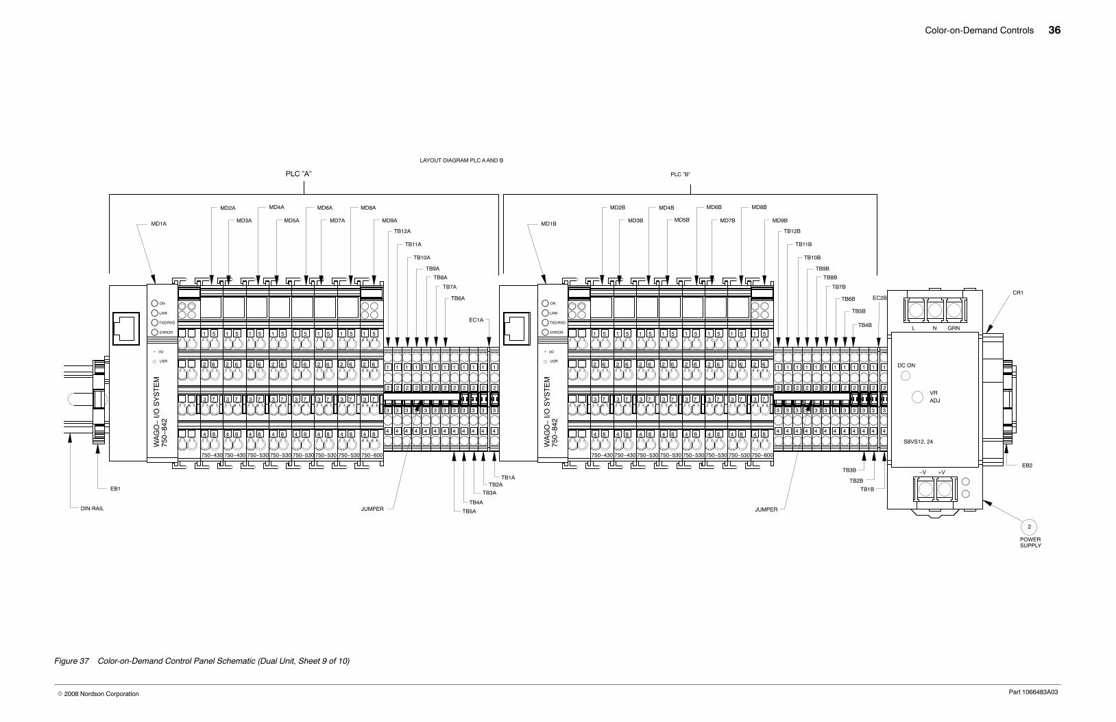
Figure 37 Color-on-Demand Control Panel Schematic (Dual Unit, Sheet 9 of 10)
Color-on-Demand Controls 37
Part 1066483A03� 2008 Nordson Corporation
SPARE 1A SPARE 2A SPARE 3A SPARE 4A SPARE 5A SPARE 6A
SPARE 3A SPARE 4A
SPARE 1A SPARE 2A
SPARE 1B SPARE 2B SPARE 3B SPARE 4B
SPARE 1B
SPARE 3B
SPARE 5B SPARE 6B
SPARE 4B
SPARE 2B
LAYOUT DIAGRAM PLC A AND B
22 66 22 66 22 66 22 66 22 66 22 66 22 66 22 66
55115511551155115511551155115511
66226622662266226622662266226622
55115511551155115511551155115511
I/OI/O
USRUSR
ONON
LINKLINK
TXD/RXDTXD/RXD
ERRORERROR
USRUSR
I/OI/O
ERRORERROR
TXD/RXDTXD/RXD
LINK
ON
PLC A LED DEFINITIONSPLC A LED DEFINITIONS PLC B LED DEFINITIONS
PS1A
CCSA
SW1A RS1A
CVBA
DOCA
RS2A
BIT4A
BIT2A BIT1A
BIT3A
BIT5A RM1ASCCA
CCDA P2AE
C27AEC28AE
C25AEC26AE
C24AE
C22AE
C20AE
C18AE C17AE
C19AE
C21AE
C23AE C16AE
C14AE
C12AE
C10AE C9AE
C11AE
C13AE
C15AE C8AE
C6AE
C4AE
C2AE C1AE
C3AE
C5AE
C7AE D2AED1AE
MD2A MD3A MD4A MD6AMD5A MD7A MD8A MD9A
COLOR−ON−DEMAND CONTROLS PLC LABELS
MD9BMD8BMD7BMD5B MD6BMD4BMD3BMD2B
SW1B
CCSB
PS1B DOCB
CVBB
RS1B RS2B
BIT4B
BIT2B BIT1B
BIT3B
BIT5B SCCB
CCDB
C28BE
C26BE C25BE
C27BE
P2BE
RM1B C24BE
C22BE
C20BE
C18BE C17BE
C19BE
C21BE
C23BE C16BE
C14BE
C12BE
C10BE C9BE
C11BE
C13BE
C15BE C8BE
C6BE
C4BE
C2BE C1BE
C3BE
C5BE
C7BE D1BE D2BE
MD1A MD1B
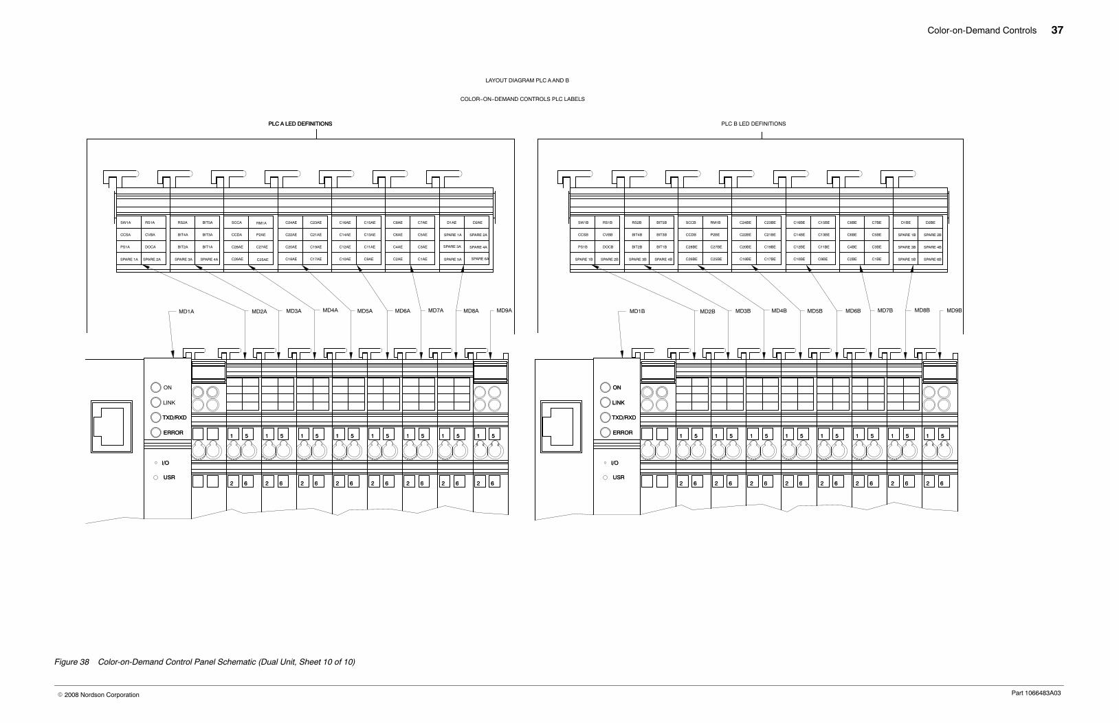
Figure 38 Color-on-Demand Control Panel Schematic (Dual Unit, Sheet 10 of 10)